Dispersion control with reflection grisms of an ultra-broadband spectrum approaching a full
octave
Tai H. Dou,1 Raphael Tautz,1,2 Xun Gu,1 Gilad Marcus,1 Thomas Feurer,3 Ferenc Krausz,1,4 and Laszlo Veisz1,*
1Max-Planck-Institut für Quantenoptik, Hans-Kopfermann-Str. 1, 85748 Garching, Germany 2 LS für Photonik und Optoelektronik and CeNS, LMU München, Amalienstr. 54, 80797 München, Germany
3Institute of Applied Physics, University of Bern, Sidlerstrasse 5, CH-3012 Bern, Switzerland 4LS für Laserphysik, LMU München, Am Coulombwall 1, 85748, Garching, Germany
Abstract: We report the design, implementation, and characterization of a grism-pair stretcher in a near-infrared noncollinear optical parametric chirped-pulse amplifier (OPCPA) that is capable of controlling a bandwidth of 440 nm. Our dynamic dispersion control scheme relies on the grism stretcher working in conjunction with an acousto-optic programmable dispersive filter (Dazzler) to jointly compensate large amount of material dispersion. A spectral interference technique is used to characterize the spectral phase of the grism stretcher. This ultra-broadband device opens up the way to generate sub-2-cycle laser pulses.
1. E. Goulielmakis, M. Schultze, M. Hofstetter, V. S. Yakovlev, J. Gagnon, M. Uiberacker, A. L. Aquila, E. M. Gullikson, D. T. Attwood, R. Kienberger, F. Krausz, and U. Kleineberg, “Single-cycle nonlinear optics,” Science 320(5883), 1614–1617 (2008).
2. G. Tsakiris, K. Eidmann, J. Meyer-ter-Vehn, and F. Krausz, “Route to intense single attosecond pulses,” N. J. Phys. 8, 19 (2006).
3. K. Schmid, L. Veisz, F. Tavella, S. Benavides, R. Tautz, D. Herrmann, A. Buck, B. Hidding, A. Marcinkevičius, U. Schramm, M. Geissler, J. Meyer-Ter-Vehn, D. Habs, and F. Krausz, “Few-cycle laser-driven electron acceleration,” Phys. Rev. Lett. 102(12), 124801 (2009).
4. V. V. Kulagin, V. A. Cherepenin, M. S. Hur, and H. Suk, “Theoretical investigation of controlled generation of a dense attosecond relativistic electron bunch from the interaction of an ultrashort laser pulse with a nanofilm,” Phys. Rev. Lett. 99(12), 124801 (2007).
5. M. Geissler, J. Schreiber, and J. Meyer-ter-Vehn, “Bubble acceleration of electrons with few-cycle laser pulses,” N. J. Phys. 8(9), 186 (2006).
6. D. Herrmann, L. Veisz, R. Tautz, F. Tavella, K. Schmid, V. Pervak, and F. Krausz, “Generation of sub-three-cycle, 16 TW light pulses by using noncollinear optical parametric chirped-pulse amplification,” Opt. Lett. 34(16), 2459–2461 (2009).
7. S. Witte, R. T. Zinkstok, A. L. Wolf, W. Hogervorst, W. Ubachs, and K. S. E. Eikema, “A source of 2 terawatt, 2.7 cycle laser pulses based on noncollinear optical parametric chirped pulse amplification,” Opt. Express 14(18), 8168–8177 (2006).
8. S. Adachi, N. Ishii, T. Kanai, A. Kosuge, J. Itatani, Y. Kobayashi, D. Yoshitomi, K. Torizuka, and S. Watanabe, “5-fs, Multi-mJ, CEP-locked parametric chirped-pulse amplifier pumped by a 450-nm source at 1 kHz,” Opt. Express 16(19), 14341–14352 (2008).
9. D. Herrmann, C. Homann, R. Tautz, M. Scharrer, P. St. J. Russell, F. Krausz, L. Veisz, and E. Riedle, “Approaching the full octave: noncollinear optical parametric chirped pulse amplification with two-color pumping,” Opt. Express 18(18), 18752–18762 (2010).
10. R. L. Fork, O. E. Martinez, and J. P. Gordon, “Negative dispersion using pairs of prisms,” Opt. Lett. 9(5), 150–152 (1984).
11. D. Strickland, and G. Mourou, “Compression of amplified chirped optical pulses,” Opt. Commun. 56(3), 219–221 (1985).
#138162 - $15.00 USD Received 16 Nov 2010; revised 12 Dec 2010; accepted 13 Dec 2010; published 17 Dec 2010(C) 2010 OSA 20 December 2010 / Vol. 18, No. 26 / OPTICS EXPRESS 27900
12. E. B. Treacy, “Optical pulse compression with diffraction grating,” IEEE J. Quantum Electron. 5(9), 454–458 (1969).
13. P. Tournois, “New diffraction grating pair with very linear dispersion for laser pulse compression,” Electron. Lett. 29(16), 1414–1415 (1993).
14. S. Kane, and J. Squier, “Grating compensation of third-order material dispersion in the normal dispersion regime: sub-100-fs chirped-pulse amplification using a fiber stretcher and grating-pair compressor,” IEEE J. Quantum Electron. 31(11), 2052–2057 (1995).
15. S. Kane, and J. Squier, “Grism-pair stretcher-compressor system for simultaneous second- and third-order dispersion compensation in chirped-pulse amplification,” J. Opt. Soc. Am. B 14(3), 661 (1997).
16. E. A. Gibson, D. M. Gaudiosi, H. C. Kapteyn, R. Jimenez, S. Kane, R. Huff, C. Durfee, and J. Squier, “Efficient reflection grisms for pulse compression and dispersion compensation of femtosecond pulses,” Opt. Lett. 31(22), 3363–3365 (2006).
17. F. Tavella, Y. Nomura, L. Veisz, V. Pervak, A. Marcinkevičius, and F. Krausz, “Dispersion management for a sub-10-fs, 10 TW optical parametric chirped-pulse amplifier,” Opt. Lett. 32(15), 2227–2229 (2007).
18. F. Verluise, V. Laude, Z. Cheng, Ch. Spielmann, and P. Tournois, “Amplitude and phase control of ultrashort pulses by use of an acousto-optic programmable dispersive filter: pulse compression and shaping,” Opt. Lett. 25(8), 575–577 (2000).
19. J. Zheng, and H. Zacharias, “Design considerations for a compact grism stretcher for non-collinear optical parametric chirped-pulse amplification,” Appl. Phys. B 96(2-3), 445–452 (2009).
20. A. P. Kovács, K. Osvay, G. Kurdi, M. Görbe, J. Klebniczki, and Z. Bor, “Dispersion control of a stretcher-compressor system with two-dimensional spectral interferometry,” Appl. Phys. B 80, 165–170 (2005).
21. C. Froehly, A. Lacourt, and J. C. Vienot, “Time impulse response and time frequency response of optical pupils.:Experimental confirmations and applications,” Nouv. Rev. Opt. 4(4), 183–196 (1973).
1. Introduction
High-peak-power few-cycle light sources are indispensible for advancing the frontiers of attosecond science, quantum coherent control, and nonlinear optics [1]. Few-cycle light pulses of high-peak power hold promise to the generation of intense, isolated attosecond pulses in the XUV [2], enabling attosecond spectroscopic applications and the control of atomic-scale electron motions. Such light sources have enabled the production of monoenergetic electrons and potentially also ions [3–5]. Presently, the only way to generate these ultra-intense light pulses is by noncollinear optical parametric chirped-pulse amplification (NOPCPA), which allows for few-cycle pulse synthesis with a broad gain bandwidth [6–8]. Recent development of the two-color pump scheme significantly further broadens the gain bandwidth [9]. This advance motivates our design of a new dispersion management system, which must cover the required spectral range. The precise dispersion management during stretching and compression holds the key to making ultrashort light pulses.
The proper selection of the stretcher and compressor is therefore very important. A compressor of negative dispersion can be either prism-based or grating-based. A prism-based compressor [10] compensates only a small amount of material dispersions, compared to the typical values used in ultra-high-power chirped-pulse amplifiers [11]. For the compression of a stretched and amplified pulse of close to a hundred picoseconds, the physical dimension of the required prisms makes its use impractical. On the other hand, grating pairs, being another popular choice for pulse compressors [12], have serious drawbacks: while dielectric gratings are not yet capable of covering our target octave-approaching bandwidth, gold-coated gratings yield only low transmission efficiency after four passes (~50%). In contrast, a positive-dispersion bulk material compressor offers the advantage of high transmission over large bandwidth, besides the ease of alignment. As for the choice of a negative-dispersion stretcher, since its efficiency is not critical, one can choose a grating-based or a grating and prism based (grism) stretcher. A grism-based stretcher is selected for its unique property of partially cancelling out the third-order dispersion so as to match the specific higher-order phase of the compressor material, which is the limiting factor of stretching and compression by such a broad bandwidth.
P. Tournois proposed that a grism pair stretcher can be designed to operate at zero third-order dispersion (TOD) [13]. Kane and Squier modified this design and showed that grisms can provide both negative group-delay-dispersion (GDD) and negative TOD and
#138162 - $15.00 USD Received 16 Nov 2010; revised 12 Dec 2010; accepted 13 Dec 2010; published 17 Dec 2010(C) 2010 OSA 20 December 2010 / Vol. 18, No. 26 / OPTICS EXPRESS 27901
demonstrated pulse compression in a chirped pulse amplifier system [14–16]. Previously Tavella et al. applied a grism stretcher in the dispersion control of an optical parametric amplifier (OPA) system in the few-cycle multi-terawatt regime [17]. In this work a programmable acousto-optic programmable dispersive filter, dubbed Dazzler (Fastlight), played a crucial role for few-cycle pulse synthesis [18]. Later J. Zheng and H. Zacharias extended the grism and Dazzler based stretcher design to various spectral ranges with 200 - 300 nm bandwidth and 750 - 850 nm central wavelength [19]. However, these grism stretcher designs cannot handle the dispersion control of an almost octave-approaching bandwidth.
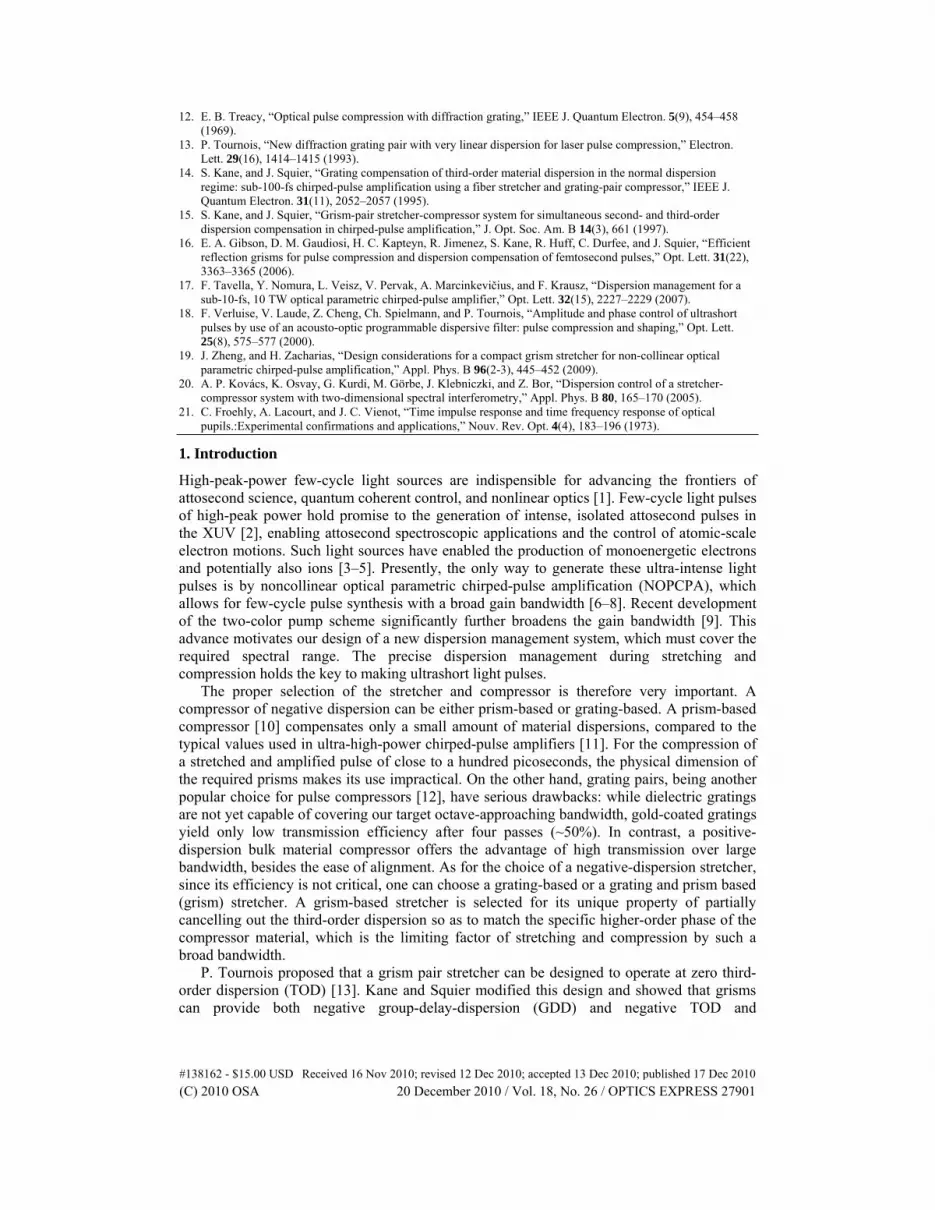
Fig. 1. Schematic of the NOPCPA experimental setup. AOPDF: Acousto-optic programmable dispersive filter, CM: Chirped mirror.
In this report we present the design, implementation, and characterization of a new grism-pair stretcher, operating at the central wavelength of 760 nm, which is capable of controlling group delay over a range of more than a hundred picoseconds with a corresponding bandwidth of 445 nm that approaches the full octave. Coupled with a Dazzler for spectral phase control, the ultra-broadband grism stretcher supports sub-5-fs pulse duration for an OPCPA system for the first time to the best of our knowledge.
The schematic layout of our stretcher-compressor system is depicted in Fig. 1. Pulse stretching is accomplished by the negative dispersion of a pair of grisms. Together with an appropriately programmed phase produced by the Dazzler, the grism stretcher is designed to compensate for the positive dispersion of (1) the glass compressor (160 mm of SF57 and 100 mm of fused silica), (2) the BBO crystals in the optical parametric chirped-pulse amplifier (OPCPA) chain (10 mm crystal thickness in total), and (3) the 45 mm of TeO2 crystal in the Dazzler, at the center wavelength of 760 nm. All higher-order dispersion of the system is well compensated by the programmed phase of the Dazzler.
#138162 - $15.00 USD Received 16 Nov 2010; revised 12 Dec 2010; accepted 13 Dec 2010; published 17 Dec 2010(C) 2010 OSA 20 December 2010 / Vol. 18, No. 26 / OPTICS EXPRESS 27902
2. Theory and simulation
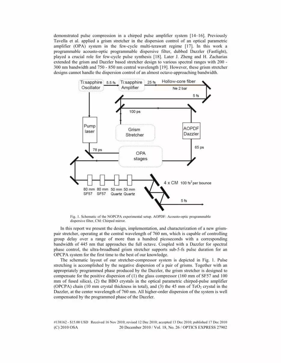
Fig. 2. Layout and raytracing of the grism stretcher. RM denotes a retro-reflecting roof mirror, β1, …,β5, the angles of the different frequency components with respect to the prism surfaces, L1, …, L6, the path travelled by these color components through the stretcher.
Our grism stretcher unit shown in Fig. 2 consists of an anti-symmetrically positioned grism pair providing negative dispersion and a retroreflector for sending the beam back right above the incoming beam along the same path. Dispersion control aims at balancing various orders of the spectral phase among all the dispersive optical components in the system to obtain a constant total group delay over the design spectral bandwidth. We performed numerical simulations on our grism stretcher with reflection gratings using the raytracing method. The spectral phase of the stretcher is given by adding up the path lengths traversed by individual frequency components through the grism setup
3 6 1 2 4 5( ) 2 ( ) ( ) ( ) ,end pL L L L L L L n Rc c
(1)
where
2 4 3 3 5
2( ) ( )sin cos( ) ,wR L L L
d
(2)
is the correction term that accounts for the phase-shift between two color components on the grating surface dropping some constant terms, with d as the grating groove period [12]. The optical length can be obtained from simple geometric considerations.
1
sinsin ,in
n
(3)
2 1,w (4)
11
sin,
cos( )w
inw
L L
(5)
#138162 - $15.00 USD Received 16 Nov 2010; revised 12 Dec 2010; accepted 13 Dec 2010; published 17 Dec 2010(C) 2010 OSA 20 December 2010 / Vol. 18, No. 26 / OPTICS EXPRESS 27903
3 2sin sin ,nd
(6)
4 3 ,w (7)
12 1
4
cos,
cosL L
(8)
5 4sin sin ,n (9)
35
,cos
grismLL
(10)
43
sin,
cosw
zL L
(11)
1 1 2 4 3 5sin sin sin ,z tip inL L L L L L (12)
45 4
1
cos,
cosL L
(13)
25
cos,
sinoutw
L L
(14)
6 sin .out inL L (15)
Here n denotes the index of refraction at the given wavelength. The following parameters are used in our final design: incident angle, in = 0°, prism apex angle w = 19°, grating
groove period d = 3.33 µm/line, incident depth inL = 25 mm, grism separation grismL = 54
mm, grism tip-to-tip distance tipL = 215.4 mm, and prism length 110.4 mm. The home-
assembled grism unit consists of an aluminum-coated plane-ruled grating (30 mm × 100 mm, Newport) and an antireflection-coated SF11 prism (Hellma). Using Eqs. (1-15) together with
the Sellmeier equation of the SF11 glass, the group delay d
GDd
can be calculated. The
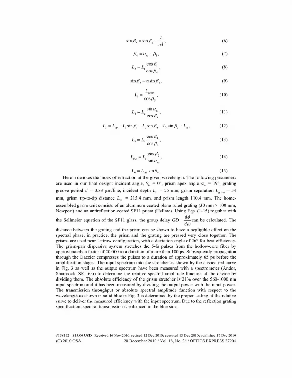
distance between the grating and the prism can be shown to have a negligible effect on the spectral phase; in practice, the prism and the grating are pressed very close together. The grisms are used near Littrow configuration, with a deviation angle of 26° for best efficiency. The grism-pair dispersive system stretches the 5-fs pulses from the hollow-core fiber by approximately a factor of 20,000 to a duration of more than 100 ps. Subsequently propagation through the Dazzler compresses the pulses to a duration of approximately 65 ps before the amplification stages. The input spectrum into the stretcher as shown by the dashed red curve in Fig. 3 as well as the output spectrum have been measured with a spectrometer (Andor, Shamrock, SR-163i) to determine the relative spectral amplitude function of the device by dividing them. The absolute efficiency of the grism stretcher is 21% over the 560-1000 nm input spectrum and it has been measured by dividing the output power with the input power. The transmission throughput or absolute spectral amplitude function with respect to the wavelength as shown in solid blue in Fig. 3 is determined by the proper scaling of the relative curve to deliver the measured efficiency with the input spectrum. Due to the reflection grating specification, spectral transmission is enhanced in the blue side.
#138162 - $15.00 USD Received 16 Nov 2010; revised 12 Dec 2010; accepted 13 Dec 2010; published 17 Dec 2010(C) 2010 OSA 20 December 2010 / Vol. 18, No. 26 / OPTICS EXPRESS 27904
Fig. 3. The efficiency curve (solid blue) shows the spectral amplitude function spanning over our design spectral range and the input spectrum (dashed red) used to measure the efficiency curve.
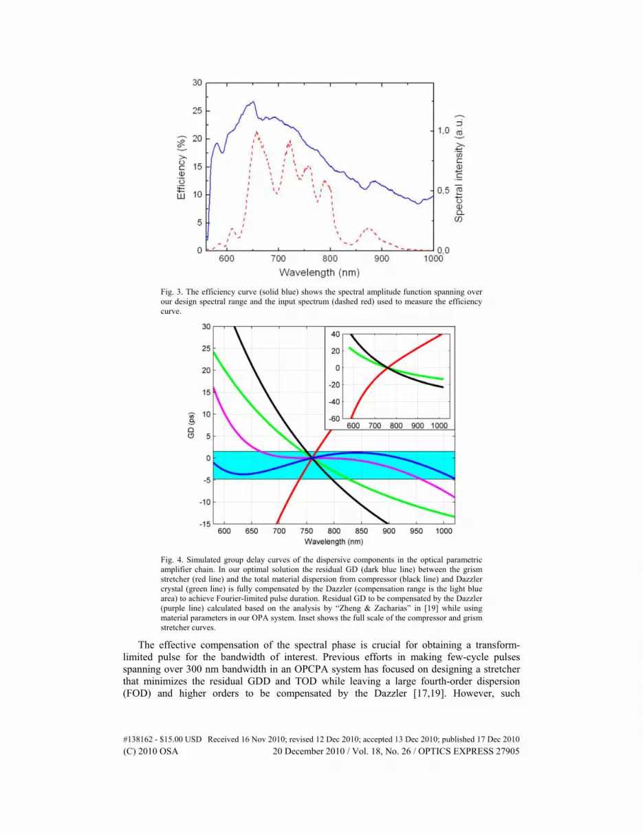
Fig. 4. Simulated group delay curves of the dispersive components in the optical parametric amplifier chain. In our optimal solution the residual GD (dark blue line) between the grism stretcher (red line) and the total material dispersion from compressor (black line) and Dazzler crystal (green line) is fully compensated by the Dazzler (compensation range is the light blue area) to achieve Fourier-limited pulse duration. Residual GD to be compensated by the Dazzler (purple line) calculated based on the analysis by “Zheng & Zacharias” in [19] while using material parameters in our OPA system. Inset shows the full scale of the compressor and grism stretcher curves.
The effective compensation of the spectral phase is crucial for obtaining a transform-limited pulse for the bandwidth of interest. Previous efforts in making few-cycle pulses spanning over 300 nm bandwidth in an OPCPA system has focused on designing a stretcher that minimizes the residual GDD and TOD while leaving a large fourth-order dispersion (FOD) and higher orders to be compensated by the Dazzler [17,19]. However, such
#138162 - $15.00 USD Received 16 Nov 2010; revised 12 Dec 2010; accepted 13 Dec 2010; published 17 Dec 2010(C) 2010 OSA 20 December 2010 / Vol. 18, No. 26 / OPTICS EXPRESS 27905
approaches result in a large group delay which cannot be compensated by the Dazzler over the targeted spectral range. The goal of this new study is to design a grism stretcher which does not specifically minimize the residual GDD and TOD, but rather optimizes the residual GDD, TOD, and FOD in such a way that the Dazzler can operate within its compensation range. For this purpose, the material dispersion in the entire OPA chain, including that of the Dazzler crystal, is computed and a new grism stretcher is designed to better match the higher-order dispersion of the system. Our study reveals that by distributing dispersion compensation into all three orders, instead of minimizing only the first two orders, the combination of the Dazzler and the grism stretcher is able to compensate the dispersion over a larger spectral range. In this way, the programmed phase of the Dazzler compensates for a combination of all three orders of spectral phase without truncating our aimed spectral range.
The group delay curves of the new stretcher, the positive dispersion materials and the Dazzler programmed phase are plotted in Fig. 4. For comparison, a simulation of a stretcher that follows the design principle used by J. Zheng and H. Zacharias [19], i.e. minimizing the GDD and TOD, has been performed using our OPCPA system parameters. The group-delay compensation range of the Dazzler programmable group delay in our target spectral range is 6.3 ps according to its specifications. From Fig. 4 it is clear that the Dazzler target group-delay curve for our newly designed stretcher-compressor system falls within the compensation range, while that based on [19] does not. The simulation results are listed in Table 1 for comparing the stretcher design between these two methods. If the stretcher is designed to compensate practically all the GDD and TOD of the entire system, the residual Dazzler group-delay curve is indeed flatter about the central wavelength, but the larger remaining FOD causes a rapid GD change at both ends of the spectral range, thus leading to a reduced effective spectral range. On the other hand, in our approach of combining the first three dispersion orders, the design allows for a lower residual FOD value and instead of eliminating GDD and TOD, it allocates some amount of them to the Dazzler. The more even distribution of different orders of dispersion prevents from the Dazzler from being overloaded with an unmanageably large excursion of GD. Consequently, the programmed GD curve of the Dazzler is contained within its specified compensation range.
Table 1. Comparison of the two grism stretcher designs
GDD (fs2) TOD (fs3) FOD (fs4) Dazzler
Compensation Range (nm)
Zheng & Zacharias [19]
Grism 70476 42496 2.29116E5 650-950
Residual 12 9.6 2.1327E5
Our Design Grism 60883 22588 1.682E5
580-1020 Residual 9605 19898 1.524E5
#138162 - $15.00 USD Received 16 Nov 2010; revised 12 Dec 2010; accepted 13 Dec 2010; published 17 Dec 2010(C) 2010 OSA 20 December 2010 / Vol. 18, No. 26 / OPTICS EXPRESS 27906
3. Measuring group delay curve with spectral interferometry
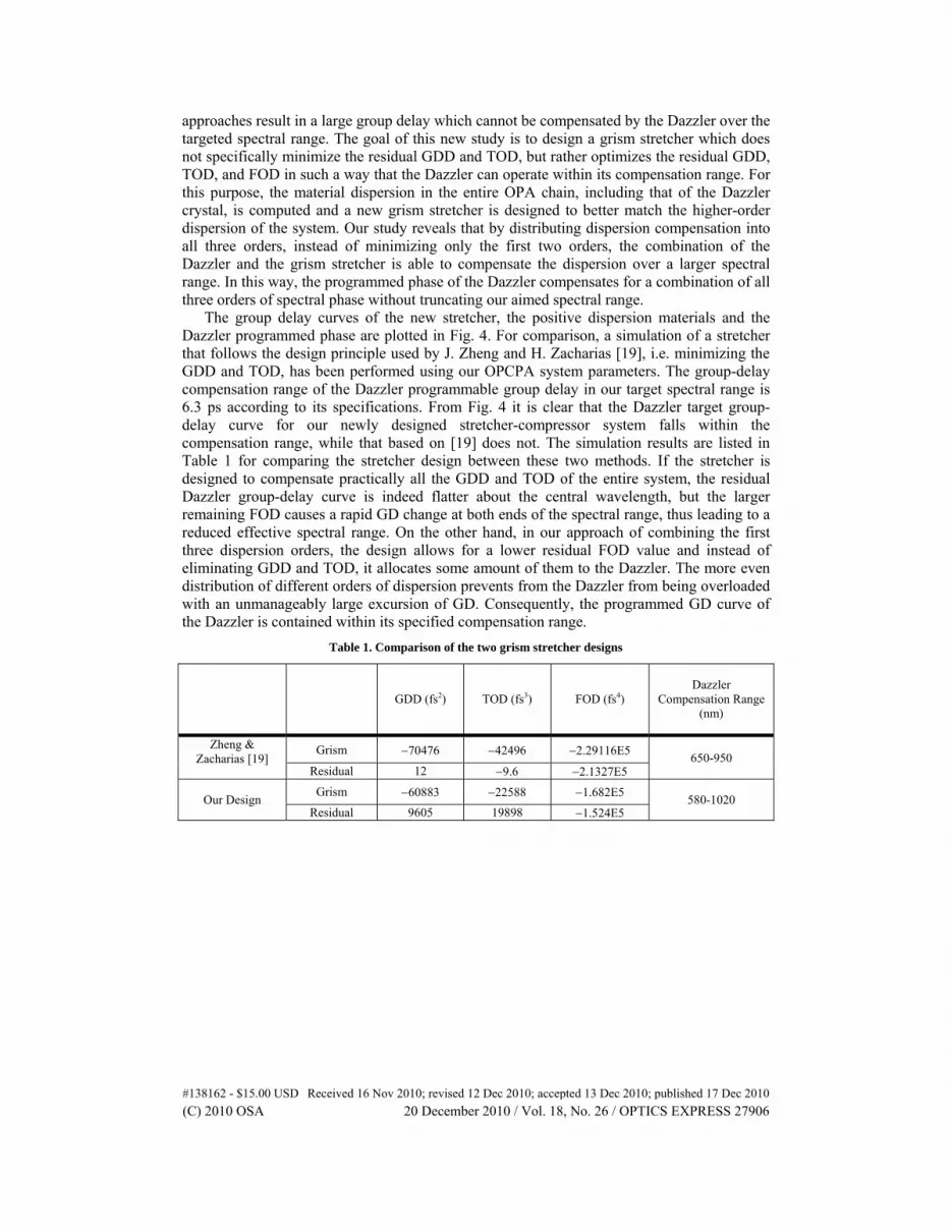
Fig. 5. The optical setup for spectral interferometry measurement. HCF stands for hollow-core fiber, BS for beamsplitter, PDS for programmable delay stage, λ/2 for half-wave plate and P for polarizer.
To accurately measure the spectral phase of our new grism stretcher and validify our design, a method of scanning spectral interferometry (SI) is applied [20] to measure the group delay curve spanning more than 50 ps. The experimental apparatus of a Mach-Zehnder-type interferometer schematically sketched in Fig. 5. The incoming beam from the hollow-core fiber is split into two by a beam splitter, of which one is directed into a scanning delay stage and the other passes through the grism stretcher. The two beams are then recombined at another beam splitter and sent to a spectrometer (Ocean Optics, USB4000 Fiber Optic Spectrometer). A half-wave plate is inserted in one beam and, combined with a polarizer after the second beam splitter, allows for fine-adjustment of the relative intensity between the two arms in order to achieve the optimal interference contrast.
The SI is a linear technique measuring the spectral phase difference between two light pulses, which, in our case, is the dispersion of the grism stretcher [21]. Normally, a SI measurement requires only one interference spectrum at one relative delay, and a Fourier transform algorithm is used to retrieve the spectral phase from the interference fringes. The interference fringes must be resolved in the entire spectrum, and therefore the spectrometer resolution must be better than the inverse of the maximum group delay difference at any wavelength between the two arms. In our case of a grism stretcher, the group delay of the stretcher spans many tens of ps across the spectrum, and thus, no spectrometer can resolve all the fringes in the interferogram. However, because of the large group delay span, interference fringes will be well localized about the wavelength when the two pulses have the same group delay. Scanning the delay between the two pulses then provides the characterization of the entire group delay curve of the system. This results from the following derivation.
#138162 - $15.00 USD Received 16 Nov 2010; revised 12 Dec 2010; accepted 13 Dec 2010; published 17 Dec 2010(C) 2010 OSA 20 December 2010 / Vol. 18, No. 26 / OPTICS EXPRESS 27907
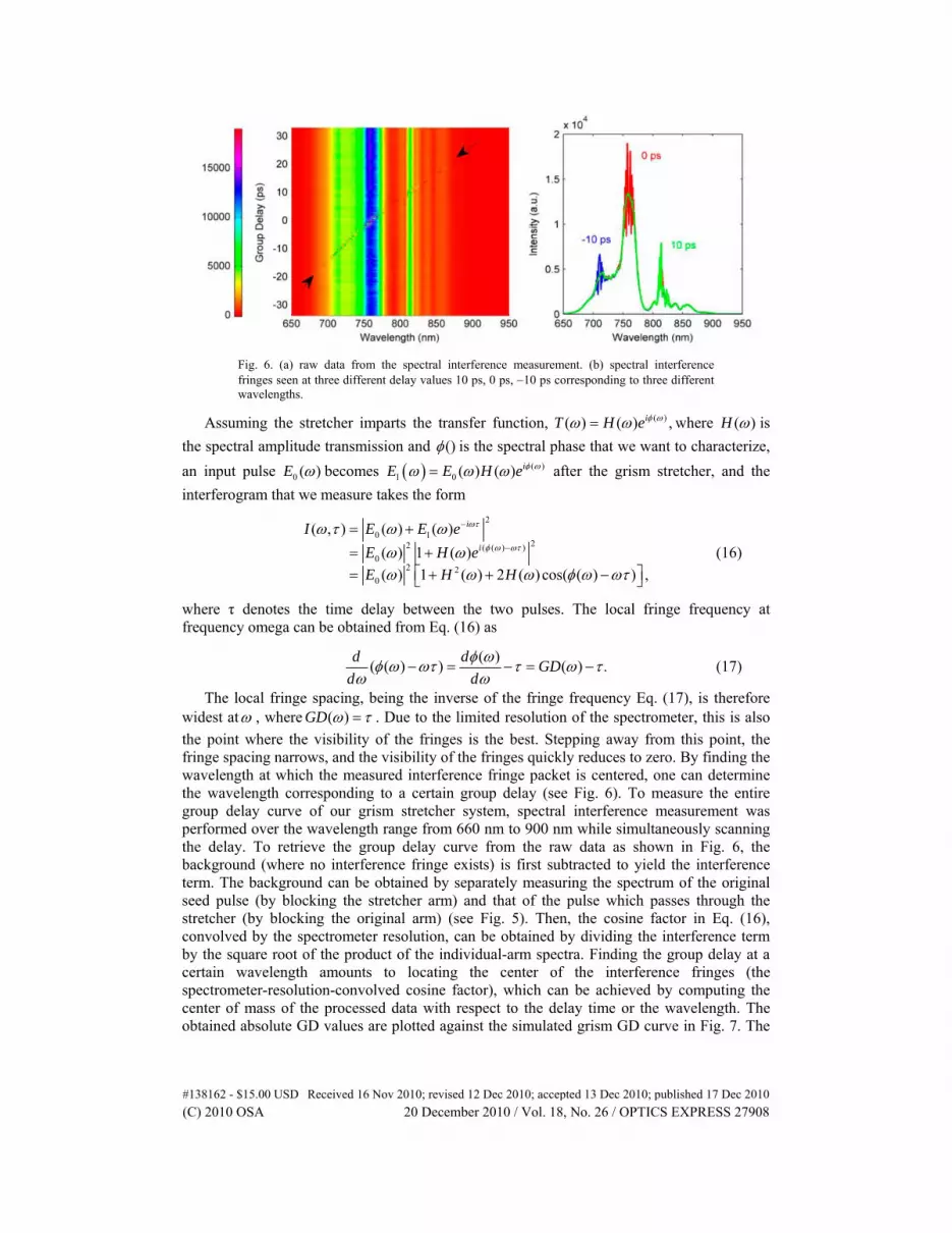
Fig. 6. (a) raw data from the spectral interference measurement. (b) spectral interference fringes seen at three different delay values 10 ps, 0 ps, 10 ps corresponding to three different wavelengths.
Assuming the stretcher imparts the transfer function, ( )( ) ( ) ,iT H e where ( )H is
the spectral amplitude transmission and () is the spectral phase that we want to characterize,
an input pulse 0 ( )E becomes ( )1 0 ( ) ( ) iE E H e after the grism stretcher, and the
interferogram that we measure takes the form
2
0 122 ( ( ) )
02 2
0
( , ) ( ) ( )
( ) 1 ( )
( ) 1 ( ) 2 ( )cos( ( ) ) ,
i
i
I E E e
E H e
E H H
(16)
where τ denotes the time delay between the two pulses. The local fringe frequency at frequency omega can be obtained from Eq. (16) as
( )
( ( ) ) ( ) .d d
GDd d
(17)
The local fringe spacing, being the inverse of the fringe frequency Eq. (17), is therefore widest at , where ( )GD . Due to the limited resolution of the spectrometer, this is also
the point where the visibility of the fringes is the best. Stepping away from this point, the fringe spacing narrows, and the visibility of the fringes quickly reduces to zero. By finding the wavelength at which the measured interference fringe packet is centered, one can determine the wavelength corresponding to a certain group delay (see Fig. 6). To measure the entire group delay curve of our grism stretcher system, spectral interference measurement was performed over the wavelength range from 660 nm to 900 nm while simultaneously scanning the delay. To retrieve the group delay curve from the raw data as shown in Fig. 6, the background (where no interference fringe exists) is first subtracted to yield the interference term. The background can be obtained by separately measuring the spectrum of the original seed pulse (by blocking the stretcher arm) and that of the pulse which passes through the stretcher (by blocking the original arm) (see Fig. 5). Then, the cosine factor in Eq. (16), convolved by the spectrometer resolution, can be obtained by dividing the interference term by the square root of the product of the individual-arm spectra. Finding the group delay at a certain wavelength amounts to locating the center of the interference fringes (the spectrometer-resolution-convolved cosine factor), which can be achieved by computing the center of mass of the processed data with respect to the delay time or the wavelength. The obtained absolute GD values are plotted against the simulated grism GD curve in Fig. 7. The
#138162 - $15.00 USD Received 16 Nov 2010; revised 12 Dec 2010; accepted 13 Dec 2010; published 17 Dec 2010(C) 2010 OSA 20 December 2010 / Vol. 18, No. 26 / OPTICS EXPRESS 27908
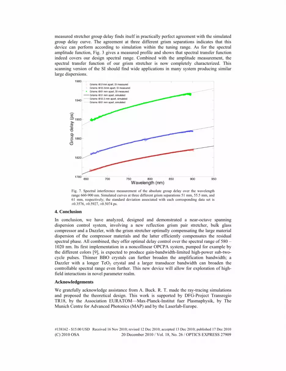
measured stretcher group delay finds itself in practically perfect agreement with the simulated group delay curve. The agreement at three different grism separations indicates that this device can perform according to simulation within the tuning range. As for the spectral amplitude function, Fig. 3 gives a measured profile and shows that spectral transfer function indeed covers our design spectral range. Combined with the amplitude measurement, the spectral transfer function of our grism stretcher is now completely characterized. This scanning version of the SI should find wide applications in many system producing similar large dispersions.
Fig. 7. Spectral interference measurement of the absolute group delay over the wavelength range 660-900 nm. Simulated curves at three different grism separations 51 mm, 55.5 mm, and 61 mm, respectively; the standard deviation associated with each corresponding data set is ±0.3576, ±0.5927, ±0.5074 ps.
4. Conclusion
In conclusion, we have analyzed, designed and demonstrated a near-octave spanning dispersion control system, involving a new reflection grism pair stretcher, bulk glass compressor and a Dazzler, with the grism stretcher optimally compensating the large material dispersion of the compressor materials and the latter efficiently compensates the residual spectral phase. All combined, they offer optimal delay control over the spectral range of 580 – 1020 nm. Its first implementation in a noncollinear OPCPA system, pumped for example by the different colors [9], is expected to produce gain-bandwidth-limited high-power sub-two-cycle pulses. Thinner BBO crystals can further broaden the amplification bandwidth; a Dazzler with a longer TeO2 crystal and a larger transducer bandwidth can broaden the controllable spectral range even further. This new device will allow for exploration of high-field interactions in novel parameter realm.
Acknowledgements
We gratefully acknowledge assistance from A. Buck. R. T. made the ray-tracing simulations and proposed the theoretical design. This work is supported by DFG-Project Transregio TR18, by the Association EURATOM—Max-Planck-Institut fuer Plasmaphysik, by The Munich Centre for Advanced Photonics (MAP) and by the Laserlab-Europe.
#138162 - $15.00 USD Received 16 Nov 2010; revised 12 Dec 2010; accepted 13 Dec 2010; published 17 Dec 2010(C) 2010 OSA 20 December 2010 / Vol. 18, No. 26 / OPTICS EXPRESS 27909