Dispersive effects in the reflection of femtosecond opticalpulses from broadband dielectric mirrors
Paolo Laporta and Vittorio Magni
The dispersive effects of high-reflectivity broadband mirrors on femtosecond optical pulses have been ana-lyzed for three different multilayer structures. In each case the high-reflectivity zone can be divided intotwo different regions symmetrically located around the mirror central frequency: high-dispersion and low-dispersion regions. The calculated temporal behavior of the reflected pulse shows high distortion of thepulse profile, a frequency chirp, and a broadening as high as a factor of 5.6, due to a single reflection, withinthe high-dispersion region. The use of these types of mirror should therefore be strictly limited to their low-dispersion side.
1. Introduction
In the last few years the duration of femtosecondoptical pulses has decreased down to values of -50 fsecfor pulses generated by the colliding-pulse mode-lockingtechnique.1- 3 Moreover, by means of compressiontechniques in optical fibers outside the cavity- 7 furtherreductions have been achieved and pulses as short as 12fsec have recently been produced.8 Due to the ex-tremely short pulse durations, the intensity shape andphase of the pulse can be greatly modified by the effectsof group velocity dispersion, in particular by thoseproduced by reflection from dielectric mirrors usedinside and outside the laser cavity. Such mirrors canbe either /4 narrowband reflectors or broadbandmultilayers with a high-reflectivity zone extending overmost of the visible spectrum.
In an earlier work9 we analyzed the effects of X/4 di-electric mirror dispersion in femtosecond dye-lasercavities. In that case, the mirror was described, in thefrequency domain, by means of a transfer function witha constant amplitude and a quadratic phase term. Inthe case of broadband multilayers, this approach is, ingeneral, not possible due to significant phase variationswithin the high-reflectivity zone of the mirrorthroughout the bandwidth of the pulse.10 Recently,pronounced pulse distortion effects were experimentally
The authors are with Centro di Elettronica Quantistica eStrumentazione Elettronica del CNR, Istituto di Fisica del Politec-nico, Piazza Leonardo da Vinci 32, 20133 Milano, Italy.
observed following reflection of 16-fsec pulses frombroadband mirrors consisting of two quarterwavestacks.1 1
In this paper we present a detailed analysis of theeffects of a single reflection of a femtosecond opticalpulse from a broadband multilayer with respect to threedifferent mirror structures. In each case we show thatthe high-reflectivity zone can be divided into two in-tervals characterized by different behavior of the phaseshift (X): a low-dispersion region and a high-dis-persion region, which lie on opposite sides in relation tothe central frequency of the mirror. Taking into ac-count the whole transfer function of the mirror (i.e., itscomplex reflectivity), we have calculated, for a Gaussianincident pulse, the broadening due to reflection as afunction of its carrier frequency and its duration.Moreover, we have shown, in a few significant cases, thetime profile of the reflected pulse obtained by the fastFourier transform (FFT) algorithm. While in thelow-dispersion region the pulse keeps its Gaussian shapeand exhibits only a slight broadening (as for a quarter-wave multilayer near resonance), in the high-dispersionregion the pulse shows marked broadening, up to afactor of -6, acquires a frequency chirp, and developsone or more satellites. All these dispersive effects arestrongly dependent on carrier frequency and pulseduration. Such types of mirrors should therefore def-initely be avoided if the optical carrier of the pulse iscentered within the high-dispersion region, but they canbe used in the low-dispersion region in the same manneras when dealing with standard quarterwave stacks.
11. Results and Discussion
Following our previous work,12 the reflection effectsof a femtosecond pulse from a broadband multilayerhave been analyzed in the frequency domain. The
mirror has accordingly been described by means of atransfer function with an intensity reflectivity R (w) anda phase b(w). Due to significant variations of 4(X)across the pulse bandwidth, no approximations of 4(w)have been made in this case. The reflected pulse is thenobtained by transforming the incident pulse in thefrequency domain, multiplying it by the mirror'stransfer function, and transforming it back into the timedomain by means of the FFT algorithm.
The complex reflectivity coefficient r(co) was calcu-lated using a general method based on a matrix for-mulation'3 and ignoring the small material dispersiondue to the layer thickness. We have considered threedifferent structures for the multilayer' 4 "5: (i) twoquarterwave stacks superimposed, centered at twodifferent wavelengths; (ii) a single stack made of a seriesof alternating high and low refractive-index layers withthe optical thickness varying in geometric progression,and (iii) a single stack, as in the previous case, with layer-optical thickness varying in arithmetic progression. Forthe sake of simplicity, we shall hereafter indicate thesethree multilayers as structures 1, 2, and 3, respectively.In the case of structure 1, the central frequency of themirror, coo, has been taken as the average value of theresonance frequencies of the two stacks; in the other twocases, the central frequency is that corresponding to theoptical thickness of the central layer of the stack.
Before proceeding with our analysis, we should notethat, for a given structure and a fixed central multilayerfrequency, two different mirrors can be made, reversingthe order of the two stacks in structure 1 or the sequenceof the layers in structures 2 and 3. Figures 1 and 2 showin both cases, for the three structures previously de-scribed, the phase shift as a function of the normalizedfrequency co/wo. The structural parameters of themultilayers are specified in the figure captions. In thesame figures, the high-reflectivity zones (R ' 99.6%) arealso indicated by dashed lines. Inside the high-reflec-tivity zone, the only one of practical interest, two dif-ferent regions of phase behavior can be seen to be almostsymmetrically located around the central frequency: ahigh-dispersion region, characterized by rapid phasevariations, and a low-dispersion region, characterizedby a slow variation of the phase. It can be seen that thereversal of the order of the two stacks [Figs. 1(a) and2(a)] or of the sequence of the layers [Figs. 1(b) and 2(b)and 1(c) and 2(c)] does not appreciably change thehigh-reflectivity zone, but it does drastically influencephase behavior. In fact, the high- and low-dispersionregions are, in practice, reversed in relation to the cen-tral frequency of the mirror.
This behavior can be understood from a physicalpoint of view, considering that, for low dispersion, amonochromatic wave is primarily reflected by the outerlayers, while for high dispersion (i.e., reflection from thesame mirror structure with reversed layer sequence) thesame wave is reflected mostly by the inner layers, twicecrossing the outer layers and thus undergoing a muchgreater phase shift. In the low-dispersion region, thephase remains approximately constant over the band-width of a femtosecond optical pulse. The behavior of
6-o
L
e9
4
2
0
6
-UaL
e
4
2
0
6
00L
e
4
2
0.7 0.8 0.9 . 1.2 1.3
Fig. 1. Mirror phase shift 4' as a function of the normalized fre-
quency w/co. (a) Structure 1, two quarterwave stacks with slightlyoverlapping high-reflectivity zones on glass substrate: [A] [0.89H]-
lF f SAV~~~~~~~~~~~~~~~~~~~~~~~~~~~~~~~l~~~<'Va~~~~~~~I I
I X
VI
co
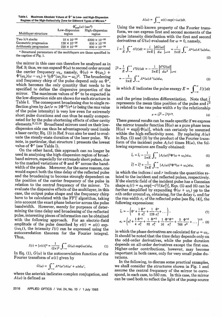
Table 1. Maximum Absolute Values of 4)" in Low- and High-DispersionRegions of the High-Reflectivity Zone for Different Types of Mirrors
(P;a(w) (sec2)Low-dispersion High-dispersion
Multilayer structure region region
Two X/4 stacks 10 X 10-30 6300 10-30
Geometric progression 120 X 10-30 850 X 10-30Arithmetic progression 220 X 10-30 800 X 10-30
a Structural parameters of the multilayers are those specified inthe caption of Fig. 1.
the mirror in this case can therefore be analyzed as inRef. 9; thus, we can expand 4*() to second order aroundthe carrier frequency COL, namely, 4'(co) = 4 (CL) +4'(C)L)( - L) + 1/2(' (WL)(W - czL)2 . The broadeningand frequency chirp of the pulse depend only on ",which becomes the only quantity that needs to bespecified to define the dispersive properties of themirror. The maximum values of " to be expected inthe low-dispersion side are shown for each structure inTable I. The consequent broadening due to single re-flection given by Ac/a- \ 2I" 2 /- 4 ( being the rms valueof the pulse intensity) is very low even for extremelyshort pulse durations and can thus be easily compen-sated for by the pulse shortening effects of other cavityelements.9 12"16 Broadband mirrors used on their low-dispersion side can thus be advantageously used insidea laser cavity; Eq. (3) in Ref. 9 can also be used to eval-uate the steady-state duration of the laser pulse. Wenote, in particular, that structure 1 presents the lowestvalue of " (see Table I).
On the other hand, this approach can no longer beused in analyzing the high-dispersion region of broad-band mirrors, especially for extremely short pulses, dueto the marked variations of b and " across the band-width of the pulse. Moreover, for the same reasons, onewould expect both the time delay of the reflected pulseand the broadening to become strongly dependent onthe position of the carrier frequency of the pulse inrelation to the central frequency of the mirror. Toevaluate the dispersive effects of the multilayer, in thiscase, the output pulse shape and the frequency chirphave to be calculated with the FFT algorithm, takinginto account the exact phase behavior across the pulsebandwidth. However, merely for purposes of deter-mining the time delay and broadening of the reflectedpulse, interesting pieces of information can be obtainedwith the following approach. For an electric-fieldamplitude of the pulse described by e(t) = a(t) exp-(iWLt), the intensity I(t) can be expressed using theautocorrelation theorem for the Fourier integral.Thus,
1(t) = e(t)12= - ) G(w) exp(icut)dw. (1)(2w )2 _
In Eq. (1), G(co) is the autocorrelation function of theFourier transform of a (t) given by
G(w) = A*( ')A(w + )dc',
where the asterisk indicates complex conjugation, andA( ) is defined as
A(cw) = 5 a(t) exp(-iwt)dt.
Using the well-known property of the Fourier trans-form, we can express first and second moments of thepulse intensity distribution with the first and secondderivatives of G (W) evaluated for w = 0, namely,
_= I i~ [dG (w)] Ct - tl(t)dt =-[ (] =J *()A(DdE X 2rE d. =0 2wE X '
(2)
t2_ =-X t2It)& = - 1 [d2G(w)]E -a 27E I dw2 jw=o
1 rX= f _ A*(.)A-(,)do,27rE -
in which E indicates the pulse energy E = f- I(t)dt
and the prime indicates differentiation. Note that trepresents the mean time position of the pulse and t 2
is related to the rms pulse width a by the relationship
a = (t 2- j2)1/2
These general results can be made specific if we expressthe mirror transfer function H(w) as a pure phase termH(w) = exp[iA(w)], which can certainly be assumedwithin the high-reflectivity zone. By replacing A(co)in Eqs. (2) and (3) by the product of the Fourier trans-form of the incident pulse Ai (o) times H(co), the fol-lowing expressions are finally obtained:
- - 1tr = ti - 2 E J Ai(W)1 24) (co + OL)dW,
t= 7 + 1 X : IAi(.)I 24)'2(W + tCL)dW,
(5)
(6)
in which the indices i and r indicate the quantities re-lated to the incident and reflected pulses, respectively.If the electric field of the incident pulse has a Gaussianshape a(t) = a exp[-t2 /(4o-1)], Eqs. (5) and (6) can befurther simplified by expanding dI(w + OL) up to thenth order around L obtaining, for the delay t and forthe rms width ar of the reflected pulse [see Eq. (4)], thefollowing expressions:
in which the phase derivatives are calculated for OL.It should be noted that the time delay depends only onthe odd-order derivatives, while the pulse durationdepends on all-order derivatives except the first one.Higher-order contributions, however, may becomeimportant in both cases, only for very small pulse du-'rations.
In the following, to discuss some practical examples,we shall consider the structures shown in Fig. 1 andassume the central frequency of the mirror to corre-spond, in each case, to 550 nm. In this case, the mirrorcan be used both to reflect the light of the pump source
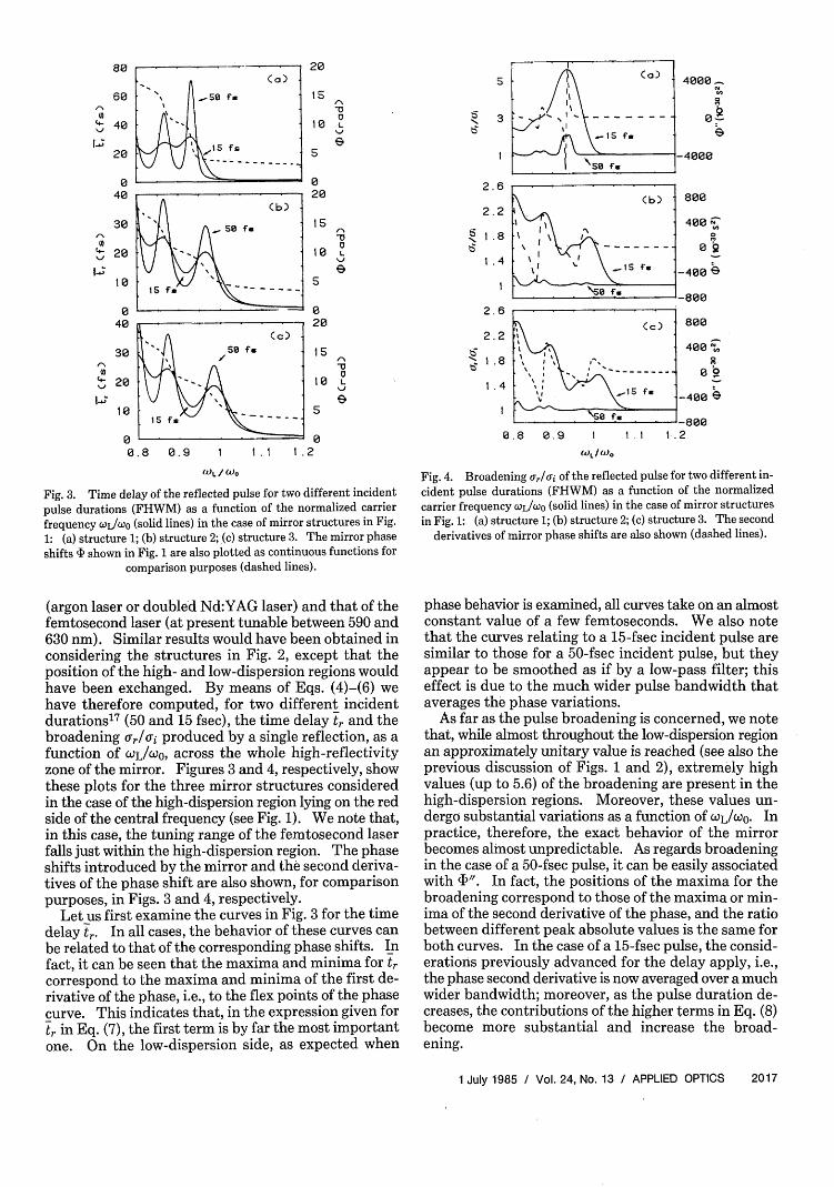
Fig. 3. Time delay of the reflected pulse for two different incidentpulse durations (FHWM) as a function of the normalized carrierfrequency WL/WO (solid lines) in the case of mirror structures in Fig.1: (a) structure 1; (b) structure 2; (c) structure 3. The mirror phaseshifts 4) shown in Fig. 1 are also plotted as continuous functions for
comparison purposes (dashed lines).
(argon laser or doubled Nd:YAG laser) and that of thefemtosecond laser (at present tunable between 590 and630 nm). Similar results would have been obtained inconsidering the structures in Fig. 2, except that theposition of the high- and low-dispersion regions wouldhave been exchanged. By means of Eqs. (4)-(6) wehave therefore computed, for two different incidentdurations' 7 (50 and 15 fsec), the time delay t and thebroadening -r/ai produced by a single reflection, as afunction of WoL/Wuo, across the whole high-reflectivityzone of the mirror. Figures 3 and 4, respectively, showthese plots for the three mirror structures consideredin the case of the high-dispersion region lying on the redside of the central frequency (see Fig. 1). We note that,in this case, the tuning range of the femtosecond laserfalls just within the high-dispersion region. The phaseshifts introduced by the mirror and the second deriva-tives of the phase shift are also shown, for comparisonpurposes, in Figs. 3 and 4, respectively.
Let us first examine the curves in Fig. 3 for the timedelay tr. In all cases, the behavior of these curves canbe related to that of the corresponding phase shifts. Infact, it can be seen that the maxima and minima for trcorrespond to the maxima and minima of the first de-rivative of the phase, i.e., to the flex points of the phasecurve. This indicates that, in the expression given fortr in Eq. (7), the first term is by far the most importantone. On the low-dispersion side, as expected when
3
2.6
2.2
Is 1.8
1.4
2.6
2.2
b 1 .8
1 .4
II (c) -I'
- I I
I f.
[ I . - S -
0.8 0.9 1
4000
0-
-4000
800
400 e
-400 ~
-800
800
400 R
0 _400
I.1 1 .2
(l)L / )
Fig. 4. Broadening a,/ai of the reflected pulse for two different in-cident pulse durations (FHWM) as a function of the normalizedcarrier frequency CWL/WOO (solid lines) in the case of mirror structuresin Fig. 1: (a) structure 1; (b) structure 2; (c) structure 3. The second
derivatives of mirror phase shifts are also shown (dashed lines).
phase behavior is examined, all curves take on an almostconstant value of a few femtoseconds. We also notethat the curves relating to a 15-fsec incident pulse aresimilar to those for a 50-fsec incident pulse, but theyappear to be smoothed as if by a low-pass filter; thiseffect is due to the much wider pulse bandwidth thataverages the phase variations.
As far as the pulse broadening is concerned, we notethat, while almost throughout the low-dispersion regionan approximately unitary value is reached (see also theprevious discussion of Figs. 1 and 2), extremely highvalues (up to 5.6) of the broadening are present in thehigh-dispersion regions. Moreover, these values un-dergo substantial variations as a function of WL/CO. Inpractice, therefore, the exact behavior of the mirrorbecomes almost unpredictable. As regards broadeningin the case of a 50-fsec pulse, it can be easily associatedwith )". In fact, the positions of the maxima for thebroadening correspond to those of the maxima or min-ima of the second derivative of the phase, and the ratiobetween different peak absolute values is the same forboth curves. In the case of a 15-fsec pulse, the consid-erations previously advanced for the delay apply, i.e.,the phase second derivative is now averaged over a muchwider bandwidth; moreover, as the pulse duration de-creases, the contributions of the higher terms in Eq. (8)become more substantial and increase the broad-ening.
Fig. 5. Broadening /lai of the reflected pulse as a function of in-cident pulse duration (FHWM) for structure 1 in Fig. 1. The carrierfrequency of the incident pulse is assumed to be that for which thebroadening is maximum (/ijwo( = 0.93,590 nm). An expanded view
is also shown.
As a final comment on Figs. 3 and 4, we may note thatthe highest values for the delay of the reflected pulse (85fsec) as well as for its broadening (5.6-see also, forcomparison purposes, the values of IDmax in Table I)within the high-dispersion region are those relating tostructure 1. On the other hand, structures 2 and 3 showa high-dispersion region that, even if it produces lessdispersive effects, is nevertheless slightly wider andextends somewhat on to the blue side of the mirror be-hind its central frequency. Thus, structure 1, whileshowing a less good dispersive behavior in the high-dispersion region, is preferable if used on its low-dis-persion side, as is also indicated by the much lowervalues of (D1'ax (see Table I).
The broadening ar/ai of the reflected pulse was alsoinvestigated as a function of incident pulse duration.Figure 5 shows this curve for a carrier frequency value
3
I-,
zH
'0
I 15f.
I ISm~ 6 1
I , I
2
-100 -50 8 so 100 ISO
TIME Cf.)
corresponding to the maximum broadening (OL =0.93 co corresponding to -590 nm) for structure 1 in Fig.1. It can be seen that, in this case, even for relativelylong pulse durations (100-150 fsec), a noticeablebroadening is still present. This and the discussion ofFig. 4 enable us to conclude that this type of mirror inparticular and all broadband mirrors in general, if usedon their high-dispersion side, should be carefullyavoided as reflectors for femtosecond pulses, both insideand outside the laser cavity.
Finally, to obtain the pulse shape and the frequencychirp of the reflected pulse, we applied the FFT algo-rithm to retransform into the time domain the fre-quency spectrum of the incident pulse, multiplied bythe whole transfer function of the mirror [i.e., by thecomplex reflection coefficient r(w)]. The results areobviously strongly dependent on the position of thepulse carrier frequency in relation to the central fre-quency of the mirror, and on the time width of the in-cident pulse. In any case, while in the low-dispersionregion the pulse maintains a close approximation to itsGaussian shape after reflection on the high-dispersionside, especially for the shortest pulses, increasingly highpulse-shape distortions are observed. The curves inFigs. 6(a), (b), and (c) show the calculated intensityshapes of the reflected pulses in the cases of structures1, 2, and 3, respectively, for an incident Gaussian pulseof 15 fsec centered at t = 0 without frequency chirp.
For each structure, the carrier frequency of the inci-dent pulse is assumed to be that for which the broad-ening is maximum and is indicated in the caption of thefigure. The shapes of the pulse reflected from thegeometric progression and from the arithmetic pro-gression stacks are almost identical [Figs. 6(b) and (c)]and are less distorted than in the double quarterwavestacks. In the latter case, Fig. 7 shows the shapes ofreflected pulses for the same incident pulse duration of
18
6
2
-100
TIME (f)Fig. 6. Intensity shape I(t) of the reflected pulse as a function of time (solid lines): (a) structure 1 in Fig. 1, olJo = 0.93 (590 nm); (b) structure2 in Fig. 1, WL/wO = 0.88 (625 nm); (c) structure 3 in Fig. 1, jL/@co = 0.89 (620 nm). The incident Gaussian pulses are plotted as dashed lines.
In each case, the carrier frequency of the incident pulse is assumed to be that for which the broadening is maximum.
5 I . 8 V I' I8 21I50 - I 00 -so 0 so 1 00 1 50 200
TIME Cfs) TIME Ufs)
I _' .\ . l
-100 -50 0 50 188 150 200
TIME (f-)
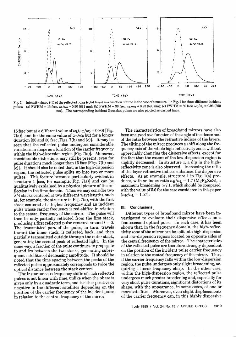
Fig. 7. Intensity shape I(t) of the reflected pulse (solid lines) as a function of time in the case of structure 1 in Fig. 1 for three different incident
nm). The corresponding incident Gaussian pulses are also plotted as dashed lines.
15 fsec but at a different value of WOL(WL/W0 = 0.90) [Fig.7(a)], and for the same value of WL/Wo but for a longerduration [30 and 50 fsec, Figs. 7(b) and (c)]. It may beseen that the reflected pulse undergoes considerablevariations in shape as a function of the carrier frequencywithin the high-dispersion region [Fig. 7(a)]. Moreover,considerable distortions may still be present, even forpulse durations much longer than 15 fsec [Figs. 7(b) and(c)]. It should also be noted that, in the high-dispersionregion, the reflected pulse splits up into two or morepulses. This feature becomes particularly evident instructure 1 [see, for example, Fig. 7(a)] and can bequalitatively explained by a physical picture of the re-flection in the time domain. Thus we may consider twoX/4 stacks centered at two different wavelengths, suchas, for example, the structure in Fig. 7(a), with the firststack centered at a higher frequency and an incidentpulse whose carrier frequency is red-shifted in relationto the central frequency of the mirror. The pulse willthen be only partially reflected from the first stack,producing a first reflected pulse centered around t = 0.The transmitted part of the pulse, in turn, travelstoward the inner stack, is reflected back, and thenpartially transmitted outside through the outer stack,generating the second peak of reflected light. In thesame way, a fraction of the pulse continues to propagateto and fro between the two stacks, generating subse-quent satellites of decreasing amplitude. It should benoted that the time spacing between the peaks of thereflected pulses approximately corresponds to twice theoptical distance between the stack centers.
The instantaneous frequency shifts of such reflectedpulses is not linear with time, unlike when the phase isgiven only by a quadratic term, and is either positive ornegative in the different satellites depending on theposition of the carrier frequency of the incident pulsein relation to the central frequency of the mirror.
The characteristics of broadband mirrors have alsobeen analyzed as a function of the angle of incidence andof the ratio between the refractive indices of the layers.The tilting of the mirror produces a shift along the fre-quency axis of the whole high-reflectivity zone, withoutappreciably changing the dispersive effects, except forthe fact that the extent of the low-dispersion region isslightly decreased. In structure 1, a dip in the high-reflectivity zone is also observed. Increasing the ratioof the layer refractive indices enhances the dispersiveeffects. As an example, structure 1 in Fig. 1(a) pro-duces, with an index ratio nH/nL = 1.7 (MgF2,ZnS), amaximum broadening '-7.1, which should be comparedwith the value of 5.6 for the case considered in this paper(nH/nL = 1.57).
Ill. Conclusions
Different types of broadband mirror have been in-vestigated to evaluate their dispersive effects on afemtosecond optical pulse. In each case, it has beenshown that, in the frequency domain, the high-reflec-tivity zone of the mirror can be split into high-dispersionand low-dispersion regions located on opposite sides ofthe central frequency of the mirror. The characteristicsof the reflected pulse are therefore strongly dependenton the position of the incident pulse carrier frequencyin relation to the central frequency of the mirror. Thus,if the carrier frequency falls within the low-dispersionregion, the pulse undergoes only slight broadening, ac-quiring a linear frequency chirp. In the other case,within the high-dispersion region, the reflected pulseundergoes much greater broadening and, especially forvery short pulse durations, significant distortions of itsshape, with the appearance, in some cases, of one ormore satellites. Moreover, even slight displacementsof the carrier frequency can, in this highly dispersive
part of the mirror, produce great variations in the shapeand in the duration of the reflected pulse.
The results obtained indicate that the broadbandmirrors cannot be used in their high-dispersion regionto reflect ultrashort light pulses propagating inside oroutside the laser cavity. On the other hand, they canbe used on their low-dispersion side, with dispersiveeffects comparable with those of narrowband X/4 mir-rors near resonance. In particular, structures made bytwo suitably superimposed X/4 stacks, even if theyproduce the strongest dispersive effects in the high-dispersion region, still show the best overall behavioron their low-dispersion side.
References1. R. L. Fork, B. I. Greene, and C. V. Shank, "Generation of Optical
Pulses Shorter than 0.1 psec by Colliding Pulse Mode-Locking,"Appl. Phys. Lett. 38, 671 (1981).
2. W. Dietel, J. J. Fontaine, and J.-C. Diels, "Intracavity PulseCompression with Glass: A New Method of Generating PulsesShorter than 60 fsec," Opt. Lett. 8, 4 (1983).
3. R. L. Fork, C. V. Shank, R. Yen, and C. A. Hirlimann, "Femto-second Optical Pulses," IEEE J. Quantum Electron. QE-19, 500(1983).
4. H. Nakatsuka, D. Grischkowsky, and A. C. Balant, "NonlinearPicosecond-Pulse Propagation Through Optical Fibers withPositive Group Velocity Dispersion," Phys. Rev. Lett. 47, 910(1981).
5. C. V. Shank, R. L. Fork, R. Yen, R. H. Stolen, and W. Tomlinson,"Compression of Femtosecond Optical Pulses," Appl. Phys. Lett.40, 761 (1982).
6. B. Nikolaus and D. Grischkowsky, " 12X Pulse Compression UsingOptical Fibers," Appl. Phys. Lett. 42, 1 (1983).
7. A. M. Weiner, J. G. Fujimoto, and E. P. Ippen, "Compression and
Shaping of Femtosecond Pulses," in Technical Digest, UltrafastPhenomena Conference, (Optical Society of America, Wash-ington, D.C., 1984), paper TuA4.
8. J.-M. Halbout and D. Grischkowsky, "12-fs Ultrashort OpticalPulse Compression at a High Repetition Rate," Appl. Phys. Lett.45, 1281 (1984).
9. S. De Silvestri, P. Laporta, and 0. Svelto, "Analysis of Quarter-Wave Dielectric-Mirror Dispersion in Femtosecond Dye-LaserCavities," Opt. Lett. 2, 335 (1984).
10. S. De Silvestri, P. Laporta, and 0. Svelto, "Effects of CavityDispersion on Femtosecond Mode-Locked Dye Laser," in Ul-trafast Phenomena IV, D. H. Auston and K. B. Eisenthal, Eds.(Springer, New York, 1984), pp. 23-26.
11. After the submission of our paper new experimental results onthis subject were published; A. M. Weiner, J. G. Fujimoto and E.P. Ippen, "Femtosecond Time-Resolved Reflectometry Mea-surements of Multiple-Layer Dielectric Mirrors," Opt. Lett. 10,71 (1985).
12. S. De Silvestri, P. Laporta, and 0. Svelto, "The Role of CavityDispersion in cw Mode-Locked Lasers," IEEE J. QuantumElectron. QE-20, 533 (1984).
13. M. Born and E. Wolf, Principles of Optics (Pergamon, New York,1970), pp. 51-70.
14. A. F. Turner and P. W. Baumeister, "Multilayer Mirrors withHigh Reflectance Over an Extended Spectral Region," Appl. Opt.5, 69 (1966).
15. H. A. Macleod, Thin Film Optical Filters (Adam Hilger, London,1969), pp. 88-110.
16. M. S. Stix and E. P. Ippen, "Pulse Shaping in Passively Mode-Locked Ring Dye Lasers," IEEE J. Quantum Electron. QE-19,520 (1983).
17. The duration of the incident (Gaussian) pulse is given throughoutthe paper as full width at half-maximum (FWHM), this being theusual notation. The broadening is instead expressed as the ratiobetween rms duration of incident and reflected pulses since, inthe case of distorted reflected pulses, the FWHM is no longermeaningful.
Meetings Calendar continued from page 1995 26-31 33rd AVS Nat. Vacuum Symp., Baltimore AVS, 335E.45th St., N.Y., N.Y. 10017
November1986
September 3-7 APS Division of Plasma Physics Mtg., Baltimore Amer.Phys. Soc., 335 E. 45th St., N.Y., N. Y. 10017
8-12 6th Int. Symp. on Gas Flow & Chemical Lasers, JerusalemS. Rosenwaks, GCL-6, co International Ltd., P.O. Box29313, Tel-Aviv 61292, Israel