72
DisplayPort 1.4 Link Layer Compliance Neal Kendall – Product Marketing Manager Teledyne LeCroy quantumdata Product Family [email protected] April – 2018

DisplayPort 1.4 Link Layer Compliance
Neal Kendall – Product Marketing Manager Teledyne LeCroy quantumdata Product Family
April – 2018

Agenda
DisplayPort 1.4 Source Link Layer Compliance Test samples (4 sample tests)
DisplayPort 1.4 Sink Link Layer Compliance Test samples (3 sample tests)
Please Check out our DisplayPort “Essentials of” Webinars:
Essentials of DisplayPort Protocols
Essentials of HDCP 2.2 Protocols
Essentials of DisplayPort Display Stream (DSC) Protocols

DisplayPort Anatomy
Main Link: Unidirectional, high-bandwidth channel used to transport video, audio and metadata and protocol control elements.
Main Link 1, 2 or 4 Lane Configurations.
Main Link 4 link rates: 1.62Gbps (Reduced Bit Rate)
2.7Gbps (High Bit Rate)
5.4Gbps (High Bit Rate 2)
8.1Gbps (High Bit Rate 3)
No clock channel. Sink recovers clock using link transitions. Pixel clock recovered from the link symbol clock using Mvid/Nvid in the MSA.
Aux Channel: Bidirectional, half duplex channel with a data rate of 1Mbps. Link Training, DPCD Register status, HDCP authentication & EDID.
No separate clock for aux channel.
Hot plug lead: Connection Detection.
Interrupt mechanism with link failure.
DisplayPort Source DisplayPort Sink (Monitor/TV)
DisplayPort Cable
Main Link (Video/Audio/Control/Framing -
Isochronous Streams – 4 lanes)
Aux Channel – Link/Device Management
Hot Plug Detect – Interrupt Request
Lane 0
Lane 1
Lane 2
Lane 3

DisplayPort Main Link Protocol – One Video Frame
Video packets occur during the active video period.
Metadata: Main Stream Attributes (MSA) and Secondary Data Packets (SDP) occur during the vertical blanking period.
There is a lot of over capacity. Fill characters are zeros for filling up (stuffing) the unused link symbols.
Fill Characters Video
Metadata Control Symbols
Audio
PPS EoC
Control VBID w/
Compression
Flag Set
VERTICAL BLANKING

DisplayPort Main Link Stream Generation – Packing and Stuffing
DisplayPort
Source DisplayPort Sink
(Monitor/TV)
DisplayPort
Cable
Two types of link symbols: Data symbols (e.g.
pixel, metadata)
Control symbols (K-Chars) to frame the data symbols.
Pixel Steering – The process of mapping the pixel data to each of the 2 or 4 lanes.
Framing, Packing, Stuffing – Adding control symbols and creating Transfer Units.
Encryption – HDCP. Inter-Lane Skewing –
Offset the link symbols (by 2 link clocks) for each lane. Reduces susceptibility to external noise pulses that could corrupt critical data across all lanes.
Lane 3
En
cry
ptio
n
Encrypt
HDCP
Pa
ckin
g
Pack
Pixel
Data
Pix
el S
tee
ring
Steer
Pixel to
Lanes
Scrambler
Scrambler
Scrambler
Scrambler
Encoder
8b/10b
Encoding
Encoder
Encoder
Encoder Second-
ary
Data
Main
Stream
Video
Data
Lane 2
Lane 0
Lane 1
Stre
am
Clo
ck to
Sym
bo
l Clo
ck
Con
ve
rsio
n
Add
Inter-
lane
Skewing
La
ne
Ske
win
g
Serializer
Parallel to Serial
Conversion
Serializer
Serializer
Serializer
Scrambling
DS
C V
ide
o
DS
C P
PS
DSC
Compression
Link Layer – Phy Layer Boundary
Scrambling is used to reduce EMI by reducing the peak spectrum and therefore reducing its harmonics which cause EMI.
Scramblers also randomize “whiten” the bit stream thereby avoiding long strings of zeros or ones; this facilitates on-going clock recovery.
Scramblers need to be reset periodically to avoid error propagation.

Display Port Connection Sequence – EDID, DPCD Link Training, HDCP, DSC
DisplayPort Source DisplayPort Sink (Monitor/TV) Event(s)
Link Training – Clock Recovery
Hot Plug
Read EDID Capabilities of Sink Device
Link Training – Channel Equalization,
Symbol Lock, Lane Alignment
Read DPCD Link & DSC/FEC Capabilities of Sink
HDCP Authentication - For content protection
DisplayPort Cable
Hot Plug. Indication to the Source that there is a Display device connect to it.
EDID read. EDID is a data structure provided by a DisplayPort display that describe its capabilities to a DisplayPort video source.
DPCD read. DPCD is a data structure provided by a DisplayPort device that describe its link & DSC capabilities to a DisplayPort source.
Link Training. Link training establishes the physical link parameters (number of lanes, link rate, voltage swing, pre-emphasis, equalization) used for transmission of video and audio over the main link.
Link Training has two phases:
Clock Recovery and
Channel Equalization which includes Symbol Lock and Inter-Lane alignment.
If the video/audio content is flagged for content protection, the High-bandwidth Digital Content Protection (HDCP) authentication protocol is used.
Compressed, encrypted video transmission is initiated. Picture Parameter (PPS) metadata is transmitted, VB-ID compressed flag is set. Transmission of DSC Video Stream
Read Decompression Enable flag

Source Link Layer Compliance Tests

Emulating DisplayPort Sink to Run Link Layer Source Compliance Tests
DisplayPort Source
DisplayPort Cable
DisplayPort 1.4 Reference Sink
Example: Teledyne LeCroy
quantumdata 980 Test Platform
with DP 1.4 Video Generator /
Protocol Analyzer

Filling Out the Capabilities Declaration
Form (CDF)
Entering the CDF Information – General
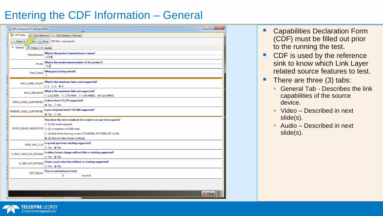
Capabilities Declaration Form (CDF) must be filled out prior to the running the test.
CDF is used by the reference sink to know which Link Layer related source features to test.
There are three (3) tabs: General Tab - Describes the link
capabilities of the source device.
Video – Described in next slide(s).
Audio – Described in next slide(s).

Entering the CDF Information – Source Video Parameters
Video – Described video capabilities of the source device.
Connection Sequence – Link Layer Compliance Tests
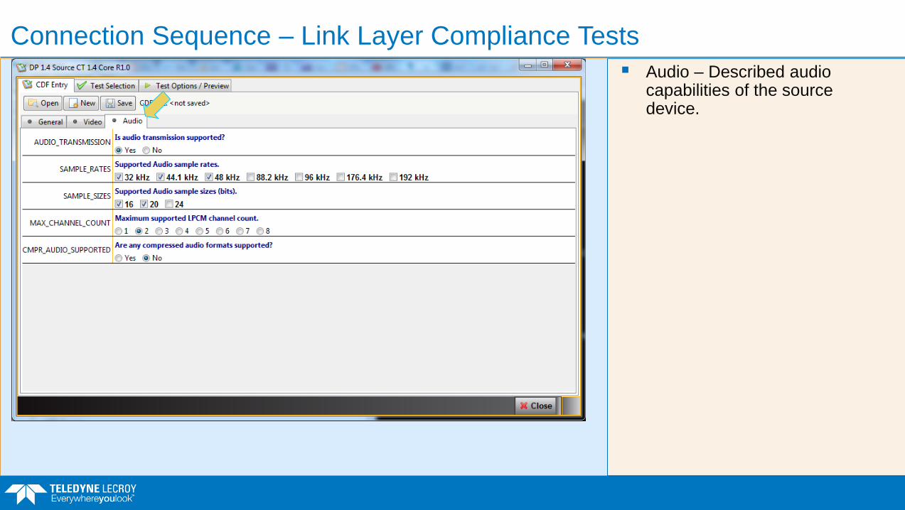
Audio – Described audio capabilities of the source device.

Source Link Layer Compliance
List of Current Tests

Source Link Layer Compliance Tests – List of Current Tests

Source Link Layer Compliance – Test 4.3.1.1 Successful Link Training
Example shows sample test results.
Shows details of subtest 12 for link training at 8.1 Gb/s link rate on four (4) lanes.

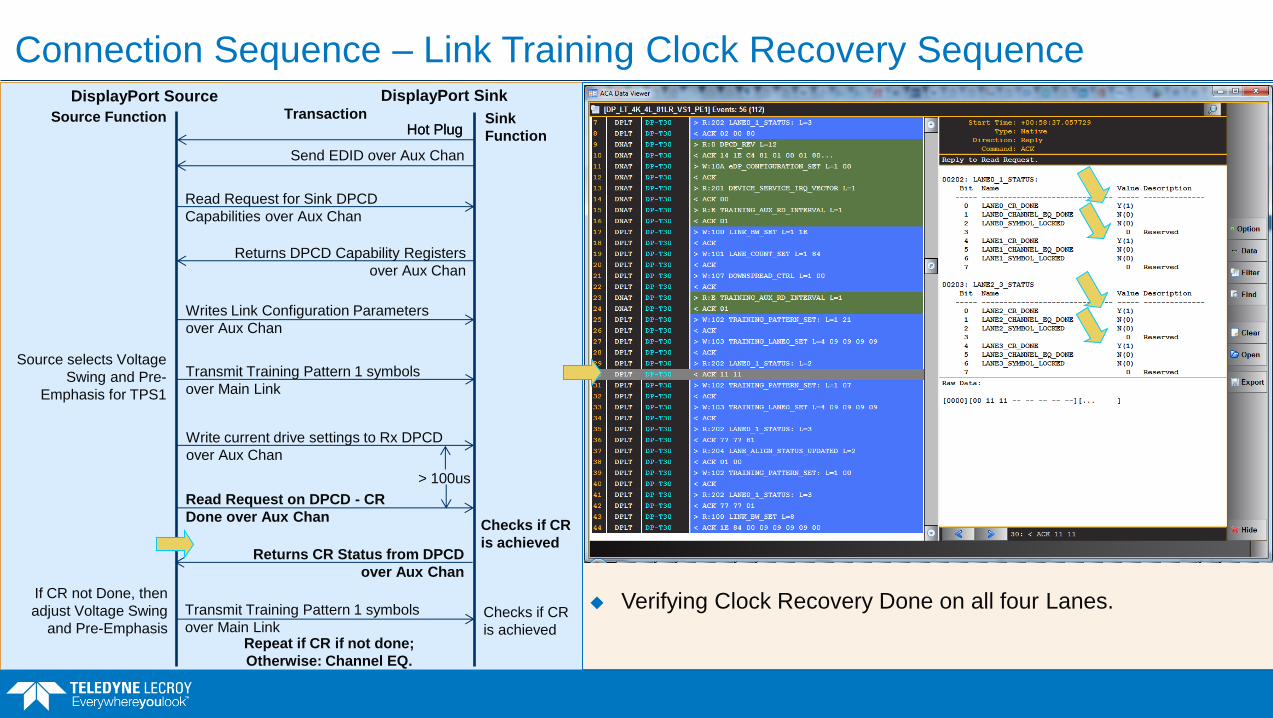
Connection Sequence – Link Training Clock Recovery Sequence DisplayPort Source DisplayPort Sink
Sink
Function
Source Function Transaction Hot Plug
Read Request for Sink DPCD
Capabilities over Aux Chan
Returns DPCD Capability Registers
over Aux Chan
If CR not Done, then
adjust Voltage Swing
and Pre-Emphasis
Writes Link Configuration Parameters
over Aux Chan
Checks if CR
is achieved
Transmit Training Pattern 1 symbols
over Main Link
> 100us
Hot Plug
Send EDID over Aux Chan
Write current drive settings to Rx DPCD
over Aux Chan
Read Request on DPCD - CR
Done over Aux Chan
Returns CR Status from DPCD
over Aux Chan
Source selects Voltage
Swing and Pre-
Emphasis for TPS1
Transmit Training Pattern 1 symbols
over Main Link Checks if CR
is achieved Repeat if CR if not done;
Otherwise: Channel EQ.
Clock Recover needed because DisplayPort, like most high speed serial interfaces, does not have a separate clock channel—the clock is derived from the bit stream.
Receiver needs a reference clock of its own at approximately the same frequency.
Very difficult to have two clocks—one on the transmitter and one on the receiver—that have the same clock frequency.
Receiver has to align its clock to the edge transitions of the incoming data stream using a PLL.
An unscrambled special sequence of bits has to be used (“training sequence”) to optimize edge sampling for clock alignment.
Clock recover begins with the following settings: Lowest drive levels, i.e. voltage swing and pre-
emphasis (unless embedded applications).
Maximum Link Rate supported, typically HBR2 5.4Gb/s/lane or HBR3 at 8.1Gb/s/lane.
Maximum number of lanes supported, typically 2 or 4.

Source Writing Link Rate (8.1Gbps) to Sink DPCD Registers to Begin Link Training
Connection Sequence – Link Training Clock Recovery Sequence DisplayPort Source DisplayPort Sink
Sink
Function
Source Function Transaction Hot Plug
Read Request for Sink DPCD
Capabilities over Aux Chan
Returns DPCD Capability Registers
over Aux Chan
If CR not Done, then
adjust Voltage Swing
and Pre-Emphasis
Writes Link Configuration Parameters
over Aux Chan
Checks if CR
is achieved
Transmit Training Pattern 1 symbols
over Main Link
> 100us
Hot Plug
Send EDID over Aux Chan
Write current drive settings to Rx DPCD
over Aux Chan
Read Request on DPCD - CR Done
over Aux Chan
Returns CR Status from DPCD
over Aux Chan
Source selects Voltage
Swing and Pre-
Emphasis for TPS1
Transmit Training Pattern 1 symbols
over Main Link Checks if CR
is achieved Repeat if CR if not done;
Otherwise: Channel EQ.

Source Writing Lane Count to Sink DPCD Registers to Begin Link Training
Connection Sequence – Link Training Clock Recovery Sequence DisplayPort Source DisplayPort Sink
Sink
Function
Source Function Transaction Hot Plug
Read Request for Sink DPCD
Capabilities over Aux Chan
Returns DPCD Capability Registers
over Aux Chan
If CR not Done, then
adjust Voltage Swing
and Pre-Emphasis
Writes Link Configuration Parameters
over Aux Chan
Checks if CR
is achieved
Transmit Training Pattern 1 symbols
over Main Link
> 100us
Hot Plug
Send EDID over Aux Chan
Write current drive settings to Rx DPCD
over Aux Chan
Read Request on DPCD - CR Done
over Aux Chan
Returns CR Status from DPCD
over Aux Chan
Source selects Voltage
Swing and Pre-
Emphasis for TPS1
Transmit Training Pattern 1 symbols
over Main Link Checks if CR
is achieved Repeat if CR if not done;
Otherwise: Channel EQ.
Source writes Downspread control indication. Downspreading or “spread spectrum” is used to reduce EMI by
reducing the amplitude of a single fundamental frequency and its harmonics across a wider spectrum.

Connection Sequence – Link Training Clock Recovery Sequence DisplayPort Source DisplayPort Sink
Sink
Function
Source Function Transaction Hot Plug
Read Request for Sink DPCD
Capabilities over Aux Chan
Returns DPCD Capability Registers
over Aux Chan
If CR not Done, then
adjust Voltage Swing
and Pre-Emphasis
Writes Link Configuration Parameters
over Aux Chan
Checks if CR
is achieved
Transmit Training Pattern 1 symbols
over Main Link
> 100us
Hot Plug
Send EDID over Aux Chan
Write current drive settings to Rx DPCD
over Aux Chan
Read Request on DPCD - CR Done
over Aux Chan
Returns CR Status from DPCD
over Aux Chan
Source selects Voltage
Swing and Pre-
Emphasis for TPS1
Transmit Training Pattern 1 symbols
over Main Link Checks if CR
is achieved Repeat if CR if not done;
Otherwise: Channel EQ.
Source Writing Training Pattern Set 1 (unscrambled) to Sink DPCD Registers.
Training Pattern 1 is used in Link Training for Clock Recovery.

Connection Sequence – Link Training Clock Recovery Sequence DisplayPort Source DisplayPort Sink
Sink
Function
Source Function Transaction Hot Plug
Read Request for Sink DPCD
Capabilities over Aux Chan
Returns DPCD Capability Registers
over Aux Chan
If CR not Done, then
adjust Voltage Swing
and Pre-Emphasis
Writes Link Configuration Parameters
over Aux Chan
Checks if CR
is achieved
Transmit Training Pattern 1 symbols
over Main Link
> 100us
Hot Plug
Send EDID over Aux Chan
Write current drive settings to Rx DPCD
over Aux Chan
Read Request on DPCD - CR Done
over Aux Chan
Returns CR Status from DPCD
over Aux Chan
Source selects Voltage
Swing and Pre-
Emphasis for TPS1
Transmit Training Pattern 1 symbols
over Main Link
Checks if CR
is achieved Repeat if CR if not done;
Otherwise: Channel EQ.
Source Writing Voltage Swing and Pre-Emphasis Levels for Link Training to Sink DPCD Registers (start with lowest levels).
Typically drive voltages are the same for all lanes.

Connection Sequence – Link Training Clock Recovery Sequence DisplayPort Source DisplayPort Sink
Sink
Function
Source Function Transaction Hot Plug
Read Request for Sink DPCD
Capabilities over Aux Chan
Returns DPCD Capability Registers
over Aux Chan
If CR not Done, then
adjust Voltage Swing
and Pre-Emphasis
Writes Link Configuration Parameters
over Aux Chan
Checks if CR
is achieved
Transmit Training Pattern 1 symbols
over Main Link
> 100us
Hot Plug
Send EDID over Aux Chan
Write current drive settings to Rx DPCD
over Aux Chan
Read Request on DPCD - CR
Done over Aux Chan
Returns CR Status from DPCD
over Aux Chan
Source selects Voltage
Swing and Pre-
Emphasis for TPS1
Transmit Training Pattern 1 symbols
over Main Link Checks if CR
is achieved Repeat if CR if not done;
Otherwise: Channel EQ.
Verifying Time Duration between Source Writing Voltage Swing and Pre-Emphasis Levels and Reading for CR Done (4.095 msec).
Connection Sequence – Link Training Clock Recovery Sequence DisplayPort Source DisplayPort Sink
Sink
Function
Source Function Transaction Hot Plug
Read Request for Sink DPCD
Capabilities over Aux Chan
Returns DPCD Capability Registers
over Aux Chan
If CR not Done, then
adjust Voltage Swing
and Pre-Emphasis
Writes Link Configuration Parameters
over Aux Chan
Checks if CR
is achieved
Transmit Training Pattern 1 symbols
over Main Link
> 100us
Hot Plug
Send EDID over Aux Chan
Write current drive settings to Rx DPCD
over Aux Chan
Read Request on DPCD - CR
Done over Aux Chan
Returns CR Status from DPCD
over Aux Chan
Source selects Voltage
Swing and Pre-
Emphasis for TPS1
Transmit Training Pattern 1 symbols
over Main Link Checks if CR
is achieved Repeat if CR if not done;
Otherwise: Channel EQ.
Verifying Clock Recovery Done on all four Lanes.

Connection Sequence – Link Training Clock Recovery
Link Training Clock Recovery.
There are 3 things that can be changed while still meeting the requirements of the video format being transmitted; listed in priority order: Drive levels, i.e. voltage swing and pre-
emphasis.
Link Rate, i.e. RBR at 1.62 Gb/s/lane through HBR3 at 8.1Gb/s/lane.
Number of lanes. Lanes can be reduced if the CR shows that the lower lanes were successfully locked.
Start
CR
Adjust Drive
Levels Reduce Link
Rate
Reduce
Lane Count*
Max Drive
Levels?
Lowest
Lane Rate? CR Done?
Transmit
Training Pattern (minimum drive
settings, max
lanes, max link
rate)
End CR
No
No
No
No Yes
Yes Yes Reduce
Lane Count?
Yes

Connection Sequence – Link Training Channel EQ, Symbol Lock, Interlane Alignment
Symbol Lock and Equalization. Starts with same link configuration and drive settings
used for Clock Recovery.
Symbol Lock is achieved when the receiver has identified and aligned on the 8b/10b symbol boundaries.
Cable acts like a low pass filter attenuating the harmonics of the fundamental frequency and smearing out the bits resulting in inter-symbol interference.
Cable equalization is the process of altering the frequency response of a video amplifier to compensate for high frequency losses in a cable.
DisplayPort Source DisplayPort Sink
Sink
Function
Source Function Transaction
If CE, SL, LA not Done,
then adjust Voltage
Swing and Pre-
Emphasis
Checks if CE,
SL, LA are
achieved
Transmit Training Pattern 2/3/4
symbols over Main Link
Read Request on DPCD – CE, SL,
LA Done over Aux Chan
Returns CE, SL, LA Status from
DPCD over Aux Chan
Source selects Voltage
Swing and Pre-
Emphasis for TPS2/3/4
Transmit Training Pattern 2/3/4 symbols
over Main Link Checks if CE,
SL, LA are
achieved Repeat if CE, SL, LA not done;
Otherwise: Link Training done.
Write current drive settings to Rx DPCD
over Aux Chan

Connection Sequence – Link Training Channel EQ, Symbol Lock, Interlane Alignment
DisplayPort Source DisplayPort Sink
Sink
Function
Source Function Transaction
If CE, SL, LA not Done,
then adjust Voltage
Swing and Pre-
Emphasis
Checks if CE,
SL, LA are
achieved
Transmit Training Pattern 2/3/4
symbols over Main Link
Read Request on DPCD – CE, SL,
LA Done over Aux Chan
Returns CE, SL, LA Status from
DPCD over Aux Chan
Source selects Voltage
Swing and Pre-
Emphasis for TPS2/3/4
Transmit Training Pattern 2/3/4 symbols
over Main Link Checks if CE,
SL, LA are
achieved Repeat if CE, SL, LA not done;
Otherwise: Link Training done.
Write current drive settings to Rx DPCD
over Aux Chan
Source Writing Training Pattern Set 4 to Sink DPCD Registers. Training Pattern 4 is always used for 8.1 Gb/s link rate for
Channel Equalization, Symbol Lock and Interlane Alignment. Only training pattern that is sent scrambled.

Connection Sequence – Link Training Channel EQ, Symbol Lock, Interlane Alignment
DisplayPort Source DisplayPort Sink
Sink
Function
Source Function Transaction
If CE, SL, LA not Done,
then adjust Voltage
Swing and Pre-
Emphasis
Checks if CE,
SL, LA are
achieved
Transmit Training Pattern 2/3/4
symbols over Main Link
Read Request on DPCD – CE, SL,
LA Done over Aux Chan
Returns CE, SL, LA Status from
DPCD over Aux Chan
Source selects Voltage
Swing and Pre-
Emphasis for TPS2/3/4
Transmit Training Pattern 2/3/4 symbols
over Main Link Checks if CE,
SL, LA are
achieved Repeat if CE, SL, LA not done;
Otherwise: Link Training done.
Write current drive settings to Rx DPCD
over Aux Chan
Source Reads Status of Channel Equalization, Symbol Lock and Inter-Lane Alignment Link Training All Done!

Connection Sequence – Channel EQ, Symbol Lock and Interlane Alignment
There are 3 things that can be changed while still meeting the requirements of the video format being transmitted; listed in priority order: Drive levels, i.e. voltage swing
and pre-emphasis.
Link Rate, i.e. RBR at 1.62 Gb/s/lane through HBR3 at 8.1Gb/s/lane.
Number of lanes. Lanes can be reduced if the CR shows that the lower lanes were successfully locked.
Start Ch EQ
Reduce Lane
Count -
Return to CR CH EQ Done
No
Yes
Set Loop Count
Transmit
Training Pattern (use CR drive
settings & link
configuration)
CH EQ
Done?
Increment
Loop Counter
Loop
Counter
Set?
No
Reduce
Lane
Count?
Yes
Max Drive
Levels?
No No
Try Reduce
Lane Count
Yes Yes Lowest
Link Rate? End Link Training
No
Yes
Adjust Drive
Levels
Return
to CR Reduce Link
Rate
Return
to CR

Source Link Layer Compliance – Test 4.3.1.1 Successful Link Training
Example shows sample test results.
Shows details of subtest 12 for link training at 8.1 Gb/s link rate on four (4) lanes.

Source Link Layer Compliance – Test 4.3.1.1 Successful Link Training

Source Link Layer Compliance – Test 4.3.1.3 Successful Link Training
Example shows sample test results.
Uses 4 Lanes with 8.1Gb/s link rate.

Source Link Layer Compliance Tests

Source Link Layer Compliance – Test 4.3.1.7 Link Training Loss of Symbol Lock
Example shows results of link training with loss of symbol lock at 8.1Gb/s.
Successful Link Training at Lower Link Rate Due to Loss of Symbol Lock During
Channel Equalization Sequence
Test objective:
Validate successful link training at lower link rate due to loss of symbol lock during channel
equalization sequence.
Note: Support of 2.7Gbps or higher link rate is optional. This test is skipped if Source DUT
supports a maximum link rate of 1.62Gbps.
Test Procedure: Repeat test procedure for each Reference Sink configuration defined in Table 4-2: Succesful
Link Training to a Lower Link Rate Test Cases up to maximum link rate supported by the
Source DUT.
1. Perform steps described under [Before Link Training] in test 4.3.1.1.
2. Perform steps described under [Clock Recovery] in test 4.3.1.1.
3. Perform Step 10 described under [Channel Equalization] in test 4.3.1.1.
4. Reference Sink clears LANEx_CR_DONE bits in DPCD Link/Sink Status Field to indicate a
loss of symbol lock.
5. Wait until the Source DUT writes to LINK_BW_SET. Verify that the Source DUT sets
LINK_BW_SET to 06h or 0Ah or 14h to attempt link training at the lower link rate by going
through the Clock Recovery sequence again.
Pass1: LINK_BW_SET = 06h and maximum link rate supported is 2.7 Gbps or LINK_BW_SET =
0Ah and maximum link rate supported is 5.4 Gbps or LINK_BW_SET = 14h and maximum link
rate supported is 8.1 Gbps
Fail1: LINK_BW_SET not = 06h and maximum link rate supported is 2.7Gbps or LINK_BW_SET
not = 0Ah and maximum link rate supported is 5.4Gbps or LINK_BW_SET not = 14h and
maximum link rate supported is 8.1Gbps
6. Perform steps described under [Clock Recovery] in test 4.3.1.1.
7. Perform steps described under [Channel Equalization] in test 4.3.1.1.

Source Link Layer Compliance – Test 4.3.1.7 Link Training Loss of Symbol Lock
Example shows results of link training with loss of symbol lock at 5.4Gb/s.

Source Link Layer Compliance
Link Maintenance Test
4.3.2 Link Maintenance
This set of tests check that the Source DUT does the appropriate action when an interrupt is signaled by IRQ
HPD pulse.
4.3.2.2 Successful Link Re-training After IRQ HPD Pulse Due to Loss of Clock Recovery
Lock
This test case verifies re-training by the Source DUT after Sink reports loss of clock recovery lock. It is
expected that the lane count and link bandwidth will be unchanged after link re-training, because the line
conditions have not changed.
This test is repeated separately for each lane supported by the Source DUT.
Test Procedure:
1. Execute test case 4.3.1.11 to enable the main link at the maximum lane count and link rate supported
by the Source DUT.
2. Reference Sink clears the LANEx_CR_DONE bits of DPCD Link Status field to indicate a loss of
clock recovery lock, and sets the LINK_STATUS_UPDATED bit.
Note: The Reference Sink is not required to change its ADJUST_REQUEST_LANEx_y fields
provided they contain a valid combination of pre-emphasis and voltage swing.
3. Reference Sink toggles IRQ HPD pulse (low pulse between 0.5ms – 1ms). HPD remains asserted for
the remainder of the test. Start Link Status Read Timer.
4. Wait until the Source DUT reads DPCD Link Status field (AUX read of address 0200h). Stop the
Link Status Read timer. Verify that the Source DUT read addresses 0200h – 0205h. Verify that the
Link Status read occurred within 100ms of the rising edge of HPD.
Pass1: Source DUT read DPCD addresses 0200h – 0205h
Fail1: Source DUT did not read DPCD addresses 0200h – 0205h
Pass2: Link Status Read started link status read within 100ms
Fail2: Link Status Read did not start within 100ms
5. Wait until the Source DUT writes to the LINK_BW_SET and LANE_COUNT_SET fields.
Pass1: LINK_BW_SET and LANE_COUNT_SET written
Fail1: TRAINING_PATTERN_SET written to 01h or 21h before LINK_BW_SET and /
LANE_COUNT_SET
6. Reference Sink clears ADJUST_REQUEST_LANE0_1 and ADJUST_REQUEST_LANE2_3 to 00h.
7. Verify that LINK_BW_SET and LANE_COUNT_SET are set to the expected values.
Pass1: LINK_BW_SET = maximum supported by Source DUT
Fail1: LINK_BW_SET not = maximum supported by Source DUT
Pass2: LANE_COUNT_SET = maximum supported by Source DUT
Fail2: LANE_COUNT_SET not = maximum supported by Source DUT
8. Wait until the Source DUT writes 01h or 21h to the TRAINING_PATTERN_SET byte in the
Reference Sink DPCD Link Configuration Field. Start the link training timer. Verify that the Source
DUT transmits Training Pattern 1 on all active lanes. Verify that the Source DUT starts with the
minimum differential voltage swing (TRAINING_LANEx_SET.VOLTAGE_SWING_SET = 00b)
and pre-emphasis disabled (TRAINING_LANEx_SET.PRE-EMPHASIS_SET = 00b) on all active
lanes.
The following exception is allowed only on the first iteration of Step 8:
If the Source DUT does not start with the minimum voltage swing and without pre-emphasis, the
Reference Sink shall skip Pass/Fail checks 2 and 3 below, keep LANEx_CR_DONE bits cleared
and repeat Step 8.
Verify that LINK_BW_SET matches the actual link bandwidth, and that LANE_COUNT_SET
matches the number of active lanes. Reference Sink sets LANEx_CR_DONE bits in DPCD Link/Sink
Status Field after CR lock is achieved and at least 100us after link training begins.
Pass1: Training Pattern 1 detected on all enabled lanes when TRAINING_PATTERN_SET is written
Fail1: Training Pattern 1 not sent on lanes {report lanes without TP1} when
TRAINING_PATTERN_SET is written
Pass2: VOLTAGE SWING SET = 00b
Fail2: VOLTAGE SWING SET not = 00b
Pass3: PRE-EMPHASIS_SET = 00b
Fail3: PRE-EMPHASIS_SET not = 00b
Pass4: IF LINK_BW_SET = 06h AND link rate = 1.62Gbps ELSE
IFLINK_BW_SET = 0Ah AND link rate = 2.7Gbps
Fail4: IF LINK_BW_SET = 06h AND link rate not = 1.62Gbps ELSE
IF LINK_BW_SET = 0Ah AND link rate not = 2.7Gbps
Pass5: IF LANE_COUNT_SET =1 AND lane 1 is enabled AND lanes 2-4 are disabled ELSE
IF LANE_COUNT_SET = 2 AND lanes 1-2 are enabled AND lanes 3-4 are disabled ELSE
IF LANE_COUNT_SET = 4 AND lanes1-4 are enabled
Fail5: IF LANE_COUNT_SET = 1 AND (lane 1 is disabled OR any of lanes 2-4 are enabled) ELSE
IF LANE_COUNT_SET = 2 AND ((lane 1 OR lane 2 is disabled) OR
(lane 3 OR lane 4 is enabled)) ELSE
IF LANE_COUNT_SET = 4 AND any of lanes 1-4 is disabled
9. Reference Sink sets LANEx_CR_DONE bits in DPCD Link/Sink Status Field after CR lock is
achieved, and within 100us of the start of the current link training iteration.
Note1: CR lock succeeded on all active lanes
Warning1: CR lock failed on lane(s) {lanes that did not achieve CR lock}
Note: Multiple iterations through the Clock Recovery sequence with adjustment of drive strength and preemphasis
are possible if required, though not specified in this test.
10. Wait until the Source DUT writes 02h or 22h to the TRAINING_PATTERN_SET byte of Reference
Sink DPCD Link Configuration Field. Verify that the Source DUT transmits Training Pattern 2 on
all active lanes.
Pass1: Training Pattern 2 detected on all active lanes
Fail1: Training Pattern 2 not detected on lanes {lanes that do not have TP2}
11. Reference Sink sets LANEx_CHANNEL_EQ_DONE, LANEx_SYMBOL_LOCK, and
INTERLANE_ALIGN_DONE in the DPCD Link/Sink Status Field after channel equalization is
complete and verifies that Source DUT is transmitting with two link symbol inter-lane skew between
adjacent lanes (for all lane counts greater than one). LANEx_CR_DONE bits in DPCD Link/Sink
Status Field also remain set.
Note1: Equalization succeeded on all active lanes
Warning1: Equalization failed on lanes (lanes that failed equalization)
Note2: Symbol lock succeeded on all active lanes.
Warning2: Symbol lock failed on lanes {lanes that failed symbol lock}
Pass3 (2 and 4 lane cases only): All lanes are properly skewed
Fail3: (2 and 4 lane cases only): Lane N+1 is skewed by M link symbols relative to lane N
(N = 0~2, M not = 2)
Note: Up to five iterations of the Channel Equalization sequence with adjustment of voltage swing and
pre-emphasis settings are allowed, though not specified in this test.
Wait until the Source DUT writes 00h to the TRAINING_PATTERN_SET byte of Reference Sink DPCD
Link Configuration Field to indicate the end of the link training.
Result: The device passes this test if all Pass/Fail checks below pass.
Pass1: Test completed successfully
Fail1: Test was manually interrupted OR Test Timer expired during step (report which step the test was in
when interrupted)
Pass2: Link training completed successfully (report even if training result did not match target link rate
and lane count)
Report link training results:
LINK_BW_SET
LANE_COUNT_SET
VOLTAGE SWING SET
PRE-EMPHASIS_SET
Fail2: Link training failed (report this if failure of any test step causes test to abort)
Pass3: All Pass/Fail checks within the test steps succeeded
Fail3: One or more Pass/Fail checks with the test steps failed

Link Maintenance
If Link Training is successful, then Link Maintenance mode.
Link Training does not guarantee that the link will behave without errors.
In Link Maintenance mode, the Link Policy function may force a retrain if there is a failure on the link.
Link retraining is necessary when there is a loss of Clock Lock, loss of Symbol Lock or loss of Inter-Lane Alignment.
Failure results in an IRQ interrupt using the Hot Plug Detect lead. The interrupt is a low-going pulse.
Source re-initiates Link Training.
DisplayPort Source DisplayPort Sink (Monitor/TV) DisplayPort Cable
Main Link (Video/Audio/Control/Framing -
Isochronous Streams – 4 lanes)
Aux Channel – Link/Device Management
Hot Plug Detect – Interrupt Request
Lane 0
Lane 1
Lane 2
Lane 3

DP 1.4 Source Link Layer Compliance
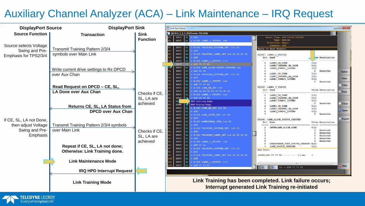
Auxiliary Channel Analyzer (ACA) – Link Maintenance – IRQ Request
Link Training has been completed. Link failure occurs;
Interrupt generated Link Training re-initiated
DisplayPort Source DisplayPort Sink
Sink
Function
Source Function Transaction
If CE, SL, LA not Done,
then adjust Voltage
Swing and Pre-
Emphasis
Checks if CE,
SL, LA are
achieved
Transmit Training Pattern 2/3/4
symbols over Main Link
Read Request on DPCD – CE, SL,
LA Done over Aux Chan
Returns CE, SL, LA Status from
DPCD over Aux Chan
Source selects Voltage
Swing and Pre-
Emphasis for TPS2/3/4
Transmit Training Pattern 2/3/4 symbols
over Main Link Checks if CE,
SL, LA are
achieved Repeat if CE, SL, LA not done;
Otherwise: Link Training done.
Write current drive settings to Rx DPCD
over Aux Chan
Link Maintenance Mode
IRQ HPD Interrupt Request
Link Training Mode

Source Link Layer Compliance – Test 4.3.2.2 Re-Training After IRQ
Example shows details of IRQ test at 8.1Gb/s link rate with a loss of clock recover on Lane 1.

Sink Link Layer Compliance Tests
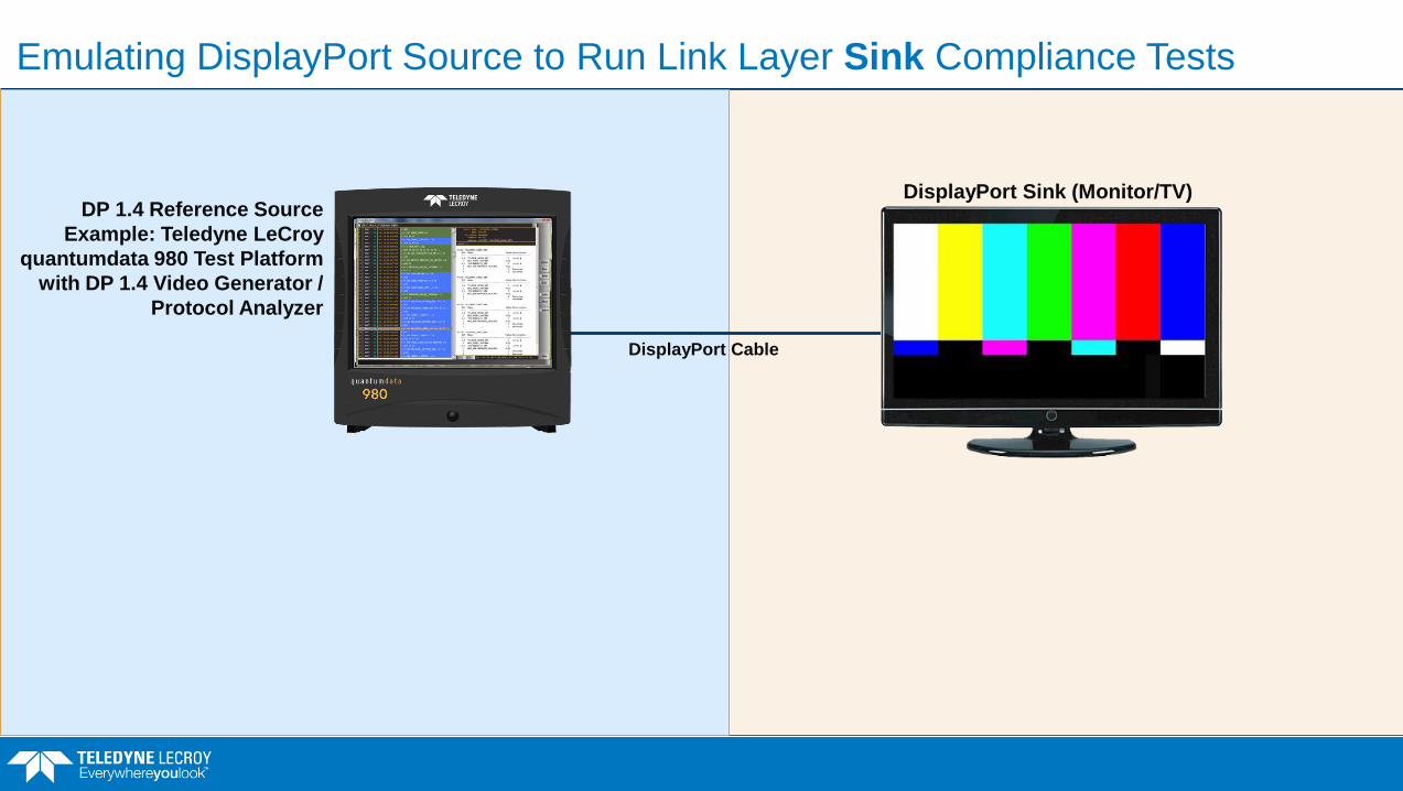
DP 1.4 Reference Source
Example: Teledyne LeCroy
quantumdata 980 Test Platform
with DP 1.4 Video Generator /
Protocol Analyzer
DisplayPort Sink (Monitor/TV)
DisplayPort Cable
Emulating DisplayPort Source to Run Link Layer Sink Compliance Tests

Entering the CDF Information – Sink General Link Layer Capabilities
Capabilities Declaration Form (CDF) must be filled out prior to the running the test.
CDF is used by the reference sink to know which Link Layer related sink features to test.
There are three (3) tabs: General Tab - Describes the link
capabilities of the sink device.
Video – Described in next slide(s).
Audio – Described in next slide(s).
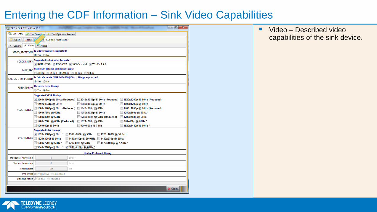
Entering the CDF Information – Sink Video Capabilities
Video – Described video capabilities of the sink device.

Entering the CDF Information – Sink Audio Capabilities
Audio – Described audio capabilities of the sink device.

Sink Link Layer Compliance
List of Current Tests

Sink Link Layer Compliance – List of Current Sink Tests
Current list of Sink Tests – Page 1

Sink Link Layer Compliance – List of Current Tests (continued)
Current list of Sink Tests – Page 2

Sink Link Layer Compliance – Test 5.4.1
Main Video Stream Reconstruction Tests

Sink Link Layer Compliance
Main Video Sink tests.

DisplayPort Main Link Stream Generation – Packing and Stuffing
DisplayPort
Source DisplayPort Sink
(Monitor/TV)
DisplayPort
Cable
Two types of link symbols: Data symbols (e.g.
pixel, metadata)
Control symbols (K-Chars) to frame the data symbols.
Pixel Steering – The process of mapping the pixel data to each of the 2 or 4 lanes.
Lane 3
En
cry
ptio
n
Encrypt
HDCP
Pa
ckin
g
Pack
Pixel
Data
Pix
el S
tee
ring
Steer
Pixel to
Lanes
Scrambler
Scrambler
Scrambler
Scrambler
Encoder
8b/10b
Encoding
Encoder
Encoder
Encoder Second-
ary
Data
Main
Stream
Video
Data
Lane 2
Lane 0
Lane 1
Stre
am
Clo
ck to
Sym
bo
l Clo
ck
Con
ve
rsio
n
Add
Inter-
lane
Skewing
La
ne
Ske
win
g
Serializer
Parallel to Serial
Conversion
Serializer
Serializer
Serializer
Scrambling
DS
C V
ide
o
DS
C P
PS
DSC
Compression

DisplayPort Main Link Protocol – Pixel Mapping
Pixels data values are mapped “steered” on the lanes that are used.
The video frame is a test pattern SMPTEbar.

DisplayPort Protocol Analyzer
Showing end of Video Display Frame, beginning of vertical blanking.
Also showing the horizontal blanking region.
Tim
e
Event Plot
Panel
Link Symbol
Panel
Data Decode
Details Panel
Data Decode
Transaction
Panel
Time
Tim
e
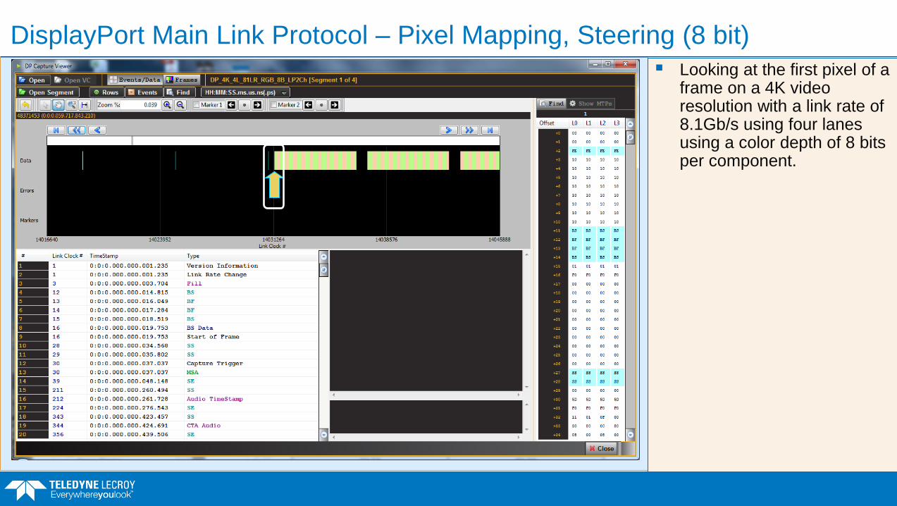
DisplayPort Main Link Protocol – Pixel Mapping, Steering (8 bit)
Looking at the first pixel of a frame on a 4K video resolution with a link rate of 8.1Gb/s using four lanes using a color depth of 8 bits per component.

DisplayPort Main Link Protocol – Pixel Mapping, Steering (8 bit)
Looking at the first video transfer unit in a frame.
Notice that the RGB values are uniform across the lanes with a pixel value of B4 representing the color of the first set of pixels in the frame:
Lane0 Lane1 Lane2 Lane3
R0-7:0 R1-7:0 R2-7:0 R3-7:0
G0-7:0 G1-7:0 G2-7:0 G3-7:0
B0-7:0 B1-7:0 B2-7:0 B3-7:0
Lane0 Lane1 Lane2 Lane3
R0-B4 R1-B4 R2-B4 R3-B4
G0-B4 G1-B4 G2-B4 G3-B4
B0-B4 B1-B4 B2-B4 B3-B4

DisplayPort Main Link Protocol – Pixel Mapping Steering (8 bit)
Looking at the first video transfer unit in a frame.
Notice that the RGB values are uniform across the lanes with a pixel value of B4 representing the color of the first set of pixels in the frame:
Lane0 Lane1 Lane2 Lane3
R0-7:0 R1-7:0 R2-7:0 R3-7:0
G0-7:0 G1-7:0 G2-7:0 G3-7:0
B0-7:0 B1-7:0 B2-7:0 B3-7:0
R0-B4 R1-B4 R2-B4 R3-B4
G0-B4 G1-B4 G2-B4 G3-B4
B0-B4 B1-B4 B2-B4 B3-B4 B 4
1011 0100 1011 0100 1011 0100 1011 0100
B 4
1011 0100 1011 0100 1011 0100 1011 0100
B 4
1011 0100 1011 0100 1011 0100 1011 0100

DisplayPort Main Link Protocol – Pixel Mapping (10bit Color Depth (30bpp)
Pixels data values are spread out mapped “steered” on the lanes that are used.
The video frame is a test pattern SMPTEbar.
Example 30 bits per pixel bit depth.

DisplayPort Main Link Protocol – Pixel Mapping, Steering (10 bit–4 Lanes)
Lane 0 Lane 1 Lane 2 Lane 3
Pixel B 4
Values 1011 0100 1011 0100 1011 0100 1011 0100
2D0 2 D
0010 1101 0010 1101 0010 1101 0010 1101
2D0 0 B
0000 1011 0000 1011 0000 1011 0000 1011
2D0 4 2
0100 0010 0100 0010 0100 0010 0100 0010
2D0 D 0
1101 0000 1100 0000 1100 0000 1100 0000
Lane 0 Lane 1 Lane 2 Lane 3
R0-9:2 R1-9:2 R2-9:2 R3-9:2
R0-1:0|G0-9:4 R1-1:0|G1-9:4 R2-1:0|G2-9:4 R3-1:0|G3-9:4
G0-3:0|B0-9:6 G1-3:0|B1-9:6 G2-3:0|B2-9:6 G3-3:0|B3-9:6
B0-5:0|R4-9:8 B1-5:0|R5-9:8 B2-5:0|R6-9:8 B3-5:0|R7-9:8
R4-7:0 R5-7:0 R6-7:0 R7-7:0

Sink Link Layer Compliance – Test 5.4.1.1 Pixel Data Reconstruction
Example test results for pixel data reconstruction.
CRC check and visual check of received video data.
Read CRC values in DPCD registers.
Details show subtest with Lane count of 4 with 8 bits per component.

Sink Link Layer Compliance – Test 5.4.1.2 – Main Stream Data Unpacking
Main Video Test – Main Stream Data Unpacking

DisplayPort Main Link Stream Generation – Packing and Stuffing
DisplayPort
Source
DisplayPort Sink
(Monitor/TV)
DisplayPort
Cable
Two types of link symbols: Data symbols (e.g.
pixel, metadata)
Control symbols (K-Chars) to frame the data symbols.
Framing, Packing, Stuffing – Adding control symbols and creating Transfer Units.
Lane 3
En
cry
ptio
n
Encrypt
HDCP
Pa
ckin
g
Pack
Pixel
Data
Pix
el S
tee
ring
Steer
Pixel to
Lanes
Scrambler
Scrambler
Scrambler
Scrambler
Encoder
8b/10b
Encoding
Encoder
Encoder
Encoder Second-
ary
Data
Main
Stream
Video
Data
Lane 2
Lane 0
Lane 1
Stre
am
Clo
ck to
Sym
bo
l Clo
ck
Con
ve
rsio
n
Add
Inter-
lane
Skewing
La
ne
Ske
win
g
Serializer
Parallel to Serial
Conversion
Serializer
Serializer
Serializer
Scrambling
DS
C V
ide
o
DS
C P
PS
DSC
Compression

DisplayPort Main Link Protocol – One Video Frame
Video packets occur during the active video period.
Metadata: Main Stream Attributes (MSA) and Secondary Data Packets (SDP) occur during the vertical blanking period.
There is a lot of over capacity. Fill characters are zeros for filling up (stuffing) the unused link symbols.
Fill Characters Video
Metadata Control Symbols
Audio
VERTICAL BLANKING
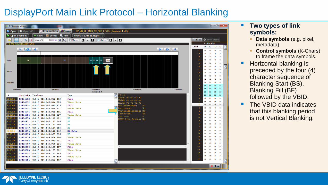
DisplayPort Main Link Protocol – Horizontal Blanking
Two types of link symbols: Data symbols (e.g. pixel,
metadata)
Control symbols (K-Chars) to frame the data symbols.
Horizontal blanking is preceded by the four (4) character sequence of Blanking Start (BS), Blanking Fill (BF) followed by the VBID.
The VBID data indicates that this blanking period is not Vertical Blanking.

DisplayPort Main Link Protocol – Framing Control Symbols
Showing end of Video Display Frame, beginning of vertical blanking.
Fill regions are visible as are some of the protocol elements in the vertical blanking region.

DisplayPort Main Link Protocol – Framing Control Symbols
Showing end of Video Display Frame, beginning of vertical blanking.
Last video element is preceded by a set of Fill Characters.
Then the four (4) character sequence of Blanking Start (BS), Blanking Fill (BF) followed by the VBID.
VBID details shown in Data Decode Details panel indicating Vertical Blanking = Yes.

Sink Link Layer Compliance – Test 5.4.1.2 Stream Unpacking/Unstuffing
Example shows Main Stream Data Unpacking Test Results.
Least Packed means less video than fill characters per transfer unit.
Uses 480p on 4 Lanes at 8.1Gb/s.

Sink Link Layer Compliance – Test 5.4.1.3 Stream Unpacking/Unstuffing
Example shows Main Stream Data Unpacking Test Results.
Most Packed means more video than fill characters per transfer unit.
Test uses high resolution format on 4 lanes at 1.62Gb/s link rate.

DisplayPort Main Link Protocol – Transfer Unit (Least Packed)
Example shows 4 lane example at 8.1Gb/s link rate with a 480p format at 8 bit color depth.
Transfer units are composed of almost entirely fill characters.

DisplayPort Main Link Protocol – Transfer Unit (More Packed)
Example shows 4 lane example at 5.4Gb/s link rate with a 4K format at 8 bit color depth.
Transfer units are predominantly fill characters for stuffing.

DisplayPort Main Link Protocol – Transfer Unit (More Packed)
Example shows 2 lane example at 5.4Gb/s link rate with a 1080p format with 8 bit color depth.
Transfer units are nearly equal amounts of video and fill characters.

DisplayPort Main Link Protocol – Transfer Unit (Most Packed)
Example shows 4 lane example at 8.1Gb/s link rate with a 4K format with 10 bit color depth.
Transfer units are mostly video.

Teledyne LeCroy – DisplayPort Phy & Protocol Testing
DisplayPort Protocol Testing at 8.1Gbps Link Rate
980B Test Platform WaveMaster
DisplayPort Phy Compliance Testing
at 8.1Gbps Link Rate

Thank you for attending Questions?
Please contact me, Neal Kendall at:
If you have any questions.
Please Check out our DisplayPort “Essentials of” Webinars:
Essentials of DisplayPort Protocols
Essentials of HDCP 2.2 Protocols
Essentials of DisplayPort Display Stream (DSC) Protocols


