Dissimilar Friction Stir Spot Welding of Aluminum to Steel
For Use in the Automotive Industry Prepared by:
Kariah Kurtenbach
Faculty Advisors:
Dr. Michael West
REU Program Director, Department of Materials and Metallurgical Engineering
Dr. Bharat Jasthi
Research Scientist III in the AMP Laboratories
Dr. Alfred Boysen
Professor, Department of Humanities
Program Information:
National Science Foundation
Grant #1157074
Research Experience for Undergraduates
Summer 2013
South Dakota School of Mines and Technology
501 E Saint Joseph Street
Rapid City, South Dakota
2
Table of Contents
Abstract….………………………..……...…………………………………………3
Objectives……………..…………………………………………………..…..3
Findings………….…………….……………………………………………...3
Introduction………………...….………..………………………………….…..…..3
Background…………..…………………………………………………..……3
Objectives………….…………….……………………………………………4
Broader Impact…....………………...……..……………………………………….4
Procedure..………………………………..………………………………………...5
Materials……………….....……………………….……………..…...…….…5
Equipment…...……….……………….…………………….………….……...5
Procedure.………………………...…………………..…………….. .……… 6
Results..……..……...……………………………………………………………..12
Welding……………..…………………………………………………..…...12
Mechanical Properties…………………………………………………………16
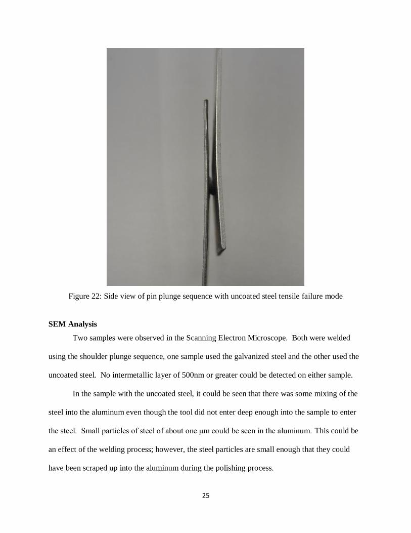
SEM Analysis………….…………….……………………………………….25
Discussion…………………….………………………………………………..….31
Conclusions.………...……………………………………………………………. 31
Summary……………..…………………………………………………..….31
Recommendations……….…………….……………………………………...32
Future Work …………………………………………………………………32
References………………………….……………………………………………..34
Acknowledgments………..…..……………………………………………..…….35
3
Abstract Objectives
The main objective of these experiments was to investigate the feasibility of using a laser
deposited tool to successfully weld Aluminum to steel provided by General Motors (GM). To do
this, first welds were made to determine whether refill Friction Stir Spot Welds could be made
between aluminum and steel. Next, process parameters should be optimized to produce the
strongest weld possible. Finally, the tool should be analyzed to ensure that minimal wear is
occurring during the welding process.
Findings
It was found that refill welds made are comparable to other Friction Stir Spot Welding
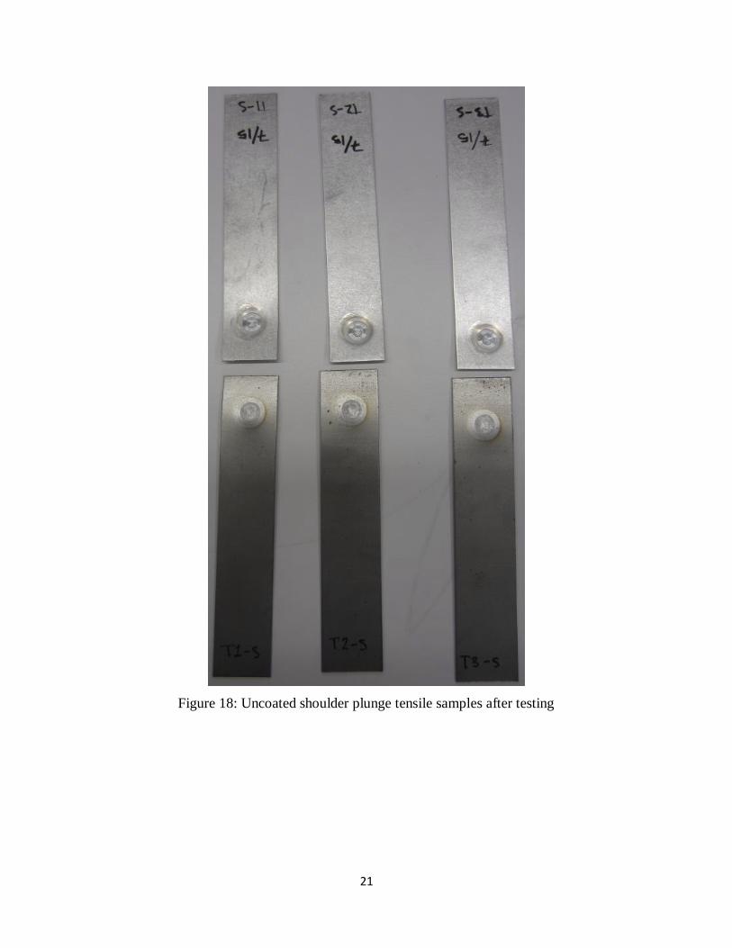
(FSSW) techniques. It was found that stronger bonds were possible using a shoulder plunge
sequence and electro-galvanized steel. Future work will include changing the location and
material of the laser deposition on the tool and further analyzing the parameters of welding.
Introduction
Background
Friction Stir Spot Welding (FSSW) is a developing solid-state welding technique that can
form strong bonds between metals previously considered “unweldable.” FSSW has been done
using many different tools and techniques. Pin tools, flat tools, refill options have all been
studied for welding one type of metal to itself. When dissimilar metals are welded together, the
differences in properties of these metals introduce unique difficulties in joining. Many
traditional forms of welding cannot be used to bond dissimilar metals and the material
differences can lead to issues with joining techniques such as Resistance Spot welding, Riveting,
and even Friction Stir Spot Welding.
4
Objectives
In these experiments, an aluminum alloy was friction stir spot welded to steel using a
refill FSSW technique. There have been several studies in which and aluminum alloy was
friction stir spot welded to steel, however, published work on a refill technique could not be
found. The main problems associated with welding aluminum to steel are the difference in
melting points of the two metals, and the tendency of aluminum and steel to form intermetallic
compounds even at relatively low temperatures. These compounds are usually very brittle
compared to the base metals used in welding and often cause a weakening in the joint. Another
common issue is the difference in hardness of the two metals.
Usually aluminum alloys are FSSW together using a steel tool, but if a steel tool was
used to weld steel, the tool would wear excessively. Harder materials that can be used to friction
weld steel are very expensive. In this study, a steel tool with a laser depositition of tungsten
carbide in a nickel matrix was used in an effort to develop a cheaper tool to make the FSSW of
aluminum to steel feasible in the automotive industry.
Broader Impact
The automobile industry has been attempting to decrease the weight of vehicles to
improve fuel efficiency. To achieve this, high strength aluminum alloys have been used to
replace steel portions of the car frame. [Sun et. al, 2013] This problem has propagated a myriad
of solutions including resistance stir welding [Zhang et. al., 2011], self-piercing rivets [Lout et. a.
2011], ultrasonic stir welding [Haddadi et. al. 2012], etc. Each technique has advantages, and
each comes with unique difficulties.
5
Friction stir spot welding is an attractive option for several reasons. Firstly, FSSW uses a
fraction of the energy needed for other welding techniques. There are no dangerous fumes that
are formed as a byproduct of FSSW so no special environments or safety equipment is needed.
In addition, spot welding techniques such as Self Piercing Rivets and Resistance Stir Welding
need consumable materials, or extra materials that are used up during the process so they cost
more by adding the cost of not only the machinery and the extra energy, but also the continuing
cost of the consumable products.
FSSW was first used in the automobile industry by Mazda. Mazda used this technique to
weld the back door panel to the rest of the car. For this project, GM will use the FSW technique
to weld an aluminum roof sheet to the side pieces of the car. The spot welds will bond the piece
of aluminum to a Resistance Spot Weld between three sheets of steel. RSW is a feasible
technique for welding steel to steel, but because of aluminums properties, RSW for aluminum
causes one electrode for RSW to degrade very quickly.
FSW is also used in the aerospace industry. Because FSW is a solid state welding
technique, pieces can be welded together without a great loss in properties from the base metal.
For this reason, FSW is commonly used to replace riveting for aluminum pressure vessels, such
as aircrafts.
Procedure Materials
Aluminum 6022 alloy
GMW2M-ST-S-CR-EG60G60G-E (cold rolled, electro-galvanized steel)
Tungsten Carbide (in nickel matrix)
Equipment
Spot Welding Machine (AMP Center SDSM&T)
Laser Deposition Machine (AMP Center SDSM&T)
MTS 858 Mini Bionix II (Tensile Machine)
6
ZEISS SUPRA 40VP Scanning Electron Microscope
LECO PR- 25 Hot Mount Press
Procedures
For these experiments aluminum alloy was spot welded to steel using refill friction stir
spot welding techniques. Aluminum 6022 alloy and cold rolled steel were the materials welded
and were provided by General Motors. The steel was supplied in both electro-galvanized and
non-galvanized forms and both were welded, tested, and compared. Before a non-galvanized
(uncoated) material was received, an attempt was made to scrapethe zinc coating off of the
galvanized steel. The results from welds made with the scraped steel are shown along with the
others.
Figure 1: FSSW Machine
The tool used was a purchased tool provided by the AMP center at SDSM&T made of
steel. A tungsten carbide compound in a nickel matrix was deposited on the pin of the tool using
laser deposition. The idea behind this tool is that the tungsten carbide (WC) deposit will be
7
inserted into the steel during welding while the remainder of the tool will remain solely in the
aluminum sheet. Because of this, cheaper tools can be used because it is not necessary that the
entire tool be made of an expensive, harder-than-steel, material.
Figure 2: WC in nickel Matrix provided by Dr. Bharat Jasthi
Figure 3: Tool pin with laser deposition provided by Mr. Todd Curtis
Welds were made using Al 6022 as the top sheet and steel as the bottom. A sleeve
plunge sequence lasting 3.93 seconds and a pin plunge sequence lasting 2 seconds were used
8
with the tool having the laser deposited nub of tungsten carbide (WC) in a nickel matrix on the
pin. The speed of the spindle was 2200rpm during the welding. Since no tungsten carbide was
present on the shoulder of the tool, the shoulder plunge weld did not penetrate the steel. During
the pin plunge sequence, the tungsten carbide nub entered the steel and the rest of the tool
remained in the aluminum.
Figure 4: Lap configuration of Aluminum and Steel sheets
Figure 5: Part configuration courtesty of General Motors
9
Figure 4: Simplified Weld sequence shoulder and pin plunges
Table 1: Welding Parameters
Tensile samples were tested using the MTS tensile machine in the AMP center. When
the samples were loaded, spacers were used to ensure that the load was applied parallel to the
weld. Samples were pulled at a rate of 0.1 inches/min and the stress/strain curve was recorded
Pin Plunge Seqence Sleeve Plunge Sequence
Time
[sec]
Spindle
n[1/min] Sleeve Pin
Travel mm
Time
[sec] Spindle
n[1/min] Sleeve Pin
Travel mm
0.00 400 -1.00 -1.00 0.00 300 -1.00 -1.00
0.50 2200 +0.00 +0.00 0.27 2200 +0.00 -0.60
1.00 2200 -0.40 +0.75 0.83 2200 +0.90 -1.68
1.00 2200 +0.02 -0.04 0.83 2200 +0.00 +0.00
0.50 2200 +0.00 +0.00 1.00 2200 +0.01 -1.00
1.00 2200 -1.50 -1.86
10
and the ultimate strength of the weld was returned. The machine is programmed to stop
automatically when the sample breaks.
Figure 5: MTS tensile tester pulling a sample
11
Figure 6: Tensile Samples to be tested
Weld analysis samples were cut using a wet saw and then machined using a milling
machine to cut the weld as close to the center as possible. Samples were hot or cold mounted
into a polymer and polished to 0.5 microns using LECO equipment. The aluminum was etched
using a sodium hydroxide solution or a hydrofluoric acid solution and the steel was etched using
a nitol solution labeled as 3% nitol. It was difficult to polish and etch the samples effectively
because of the difference in material properties. A microscope and the Scanning Electron
Microscope (SEM) were used to take close up pictures of the weld cross-sections.
The SEM analysis was performed using ZEISS SUPRA 40VP Scanning Electron
Microscope. Two macros were used in the SEM. Both were shoulder plunge samples, one weld
was made using the galvanized steel and the other was made using the uncoated steel. The weld
12
made with the uncoated steel was unetched when placed in the SEM but the aluminum had been
etched with the sodium hydroxide solution. The uncoated sample was examined to see what
mixing had occurred between the aluminum and steel while the galvanized sample was examined
to see what had happened to the zinc coating during welding. Both samples were checked for a
visible intermetallic layer.
Results
Welding
During welding there was a severe problem with the tool sticking to the welded material.
A hammer was required to knock each sample off of the welding machine. In addition, the
sticking problem was worst with the electro-galvanized steel using the pin-plunge sequence and
no samples with these parameters could be successfully produced. The main theory behind the
cause of the sticking suggests that the affinity between nickel and steel causes the atoms to
exchange places easily within their crystal structures, so the laser deposition was sticking to the
steel. Another theory is that the softened metal cools when it is pushed up into the void left by
the pin or the shoulder and subsequently sticks to the inside of the tool (Badarinarayan et al.
239). In previous refill FSSW attempts where sticking was a problem, a “fixed-position” refill
FSSW often had less sticking issues than the “shoulder-first” refill FSSW technique used in this
study (Badarinarayan et al. 239). In the future, it is advisable to try other refill FSSW techniques
and parameters as well as new material for the laser deposition to reduce and hopefully eliminate
the sticking problem. After severe sticking, excess material was cleaned off of the tool by
welding aluminum to aluminum.
13
Figure 7: Weld sticking to FSSW machine
When the cross sections of the welds were examined, it was seen that the steel was being
stirred up by the laser deposition on the pin of the tool. Pieces of steel can be seen with the
naked eye and the macrographs of the pin-plunge welds.
Figure 8: FSSW pin plunge made with scraped steel
14
Figure 9: FSSW pin plunge made with uncoated steel
Some thinning of the aluminum sheet can be seen as well in both the pin-plunge and
shoulder plunge samples. This is common for spot welds made with high rotational speeds and
greater plunge depths [Badarinarayan et al., 253].
15
Figure 10: FSSW showing thinning of aluminum sheet
No visible deformation of the steel can be seen in the macros of the shoulder plunge
samples. However, the interface between the aluminum and steel is more jagged in the uncoated
sample. The fragments of steel visible beneath the steel sheet in the uncoated sample are the
result of flash from the milling machine.
16
Figure 11: FSSW shoulder plunge with uncoated steel
Figure 12: FSSW shoulder plunge with electro-galvanized steel
Mechanical Properties
Three or four samples of each weld type were produced and tensile tested. It can be seen
that the strongest bond was formed between the aluminum alloy and the scraped steel using the
shoulder plunge sequence. The aluminum welded to the electro galvanized steel with the
shoulder plunge sequence was able to withstand the next highest ultimate tensile load and the
other results can be seen on Table 2. The weakest bond was formed with the non-galvanized
17
steel using the pin plunge sequence. Unfortunately, the galvanized and non-galvanized steel
could not be compared with the pin plunge weld. The sticking problem made it impossible to
produce a successful pin-plunge weld with the electro-galvanized steel.
Table 2: Average ultimate tensile loads for each weld type
Weld type Ultimate tensile strength
Shoulder plunge with
galvanized steel
618 ± 12 lbf 2.75 ±0.06kN
Shoulder plunge with
uncoated steel
533 ± 15 lbf 2.37 ±0.07kN
Pin Plunge with uncoated
steel
350 ± 26 lbf 1.56 ±0.12kN
Pin plunge with galvanized
steel
Welds were not completed or tested due to the sticking of the
tool to the material
Shoulder plunge with
scraped steel
764 ± 14 lbf 3.4 ± 0.06 kN
Pin Plunge with scraped
steel
552 ± 52 lbf 2.4 ± 0.23 kN
The welds made with the scraped steel were able to bear the highest loads. The tensile
samples broken also had significantly more deformation than the other samples before. It is
unlikely that the process of scraping the zinc off of the steel made the steel hot enough to change
the properties of the steel, so possible reasons for these results include that a very thin layer of
zinc remained on the steel and that the sheet was thinned by the scraping process which made
more deformation possible.
All of the shoulder plunge samples failed by shear failure of the aluminum to steel
interface. The tensile samples made from the scraped steel using the pin plunge method also
exhibited shear failure along the aluminum-steel interface. The pin-plunge samples made with
the uncoated steel, however displayed a “nugget pullout” failure.
18
Figure 13: scraped and coated steel FSSWs
Figure 14: scraped shoulder plunge tensile samples after failure
19
Figure 15: electro-galvanized shoulder plunge tensile samples after failure
Figure 16: scraped pin plunge tensile samples after failure
22
Figure 19: Close up of uncoated shoulder plunge tensile samples shear failure mode
Figure 20: uncoated pin plunge tensile
samples after testing
25
Figure 22: Side view of pin plunge sequence with uncoated steel tensile failure mode
SEM Analysis
Two samples were observed in the Scanning Electron Microscope. Both were welded
using the shoulder plunge sequence, one sample used the galvanized steel and the other used the
uncoated steel. No intermetallic layer of 500nm or greater could be detected on either sample.
In the sample with the uncoated steel, it could be seen that there was some mixing of the
steel into the aluminum even though the tool did not enter deep enough into the sample to enter
the steel. Small particles of steel of about one μm could be seen in the aluminum. This could be
an effect of the welding process; however, the steel particles are small enough that they could
have been scraped up into the aluminum during the polishing process.
27
With the galvanized steel, there was no mixing of the steel into the aluminum. However,
it could be seen in the EDS (Energy Dispersive Spectroscopy) that the zinc coating was being
pushed out of the middle of the weld and up into the aluminum on the sides of the weld. This
interlocking of the zinc into the aluminum could be the reason for the stronger welds between the
galvanized steel and the aluminum vs. the uncoated steel and the aluminum.
28
Figure 24: SEM and EDS images of shoulder plunge sequence with galvanized steel left side of
weld (there is a piece of lint in the shot. Please disregard)
29
Figure 25: SEM and EDS images of center of weld made with shoulder plunge sequence with
galvanized steel
30
Figure 26: SEM and EDS images of shoulder plunge sequence using galvanized steel right side
of weld Al-steel interface
31
Discussion Table 3: Strengths of associated spot welds
Welds were made with comparable properties to other FSSW attempts, but the results
were still lower than those found when using techniques such as self-piercing rivets. Ultimately,
it is desired that spot welds reach 90% of the strength of a FSSW bond formed between two
sheets of aluminum. More parameters need to be adjusted and welds between aluminum sheets
must be tested as well to determine if such strengths are being reached.
Conclusions
Summary
Successful refill friction stir spot welds were made between the aluminum alloy and steel
and the mechanical properties were comparable to other welds between aluminum and steel.
Material type and Thickness (mm) Weld Type Max Strength (kN) Reference
Al 6016 (1.2mm) / IF-steel (2mm) FSSW 4.5 Bozzi et. al. 2010
Al 6111 (1.15mm) / DP600 steel (1.8mm) FSSW 2.4 Liyanage et. al., 2009
AA6061-T6(2mm) / DP780 Steel(1.25mm)
SPR 6.5 Lou et al. 2013
AA6061-T6(2mm) / DP780 Steel(1.25mm)
Electroplastic SPR 7.3 Lou et al. 2013
AA6111 (1mm) / DX56-Z coated steel (1mm)
Ultrasonic spot welding
3.5 Haddadi et al. 2012
AA6008 (1.5mm) / H22YD galvanised steel (1mm)
RSW 3.3 Zhang et al. 2011
AA5754 (1.8mm) / DP 980 steel (1.4mm) Friction Bit Joining (FBJ)
6.3 Miles et al. 2009
AA6016(T6) (1.1mm) / DC04+ZE Steel (0.9mm)
Fluxless Laser beam joining
9.8 Laukant et al. 2006
AA 6022 (1mm)/ EG low carbon steel (0.7mm)
FSSW 2.75 Made and tested in AMP center
32
From the macrographs of the pin plunge sequence welds, it can be seen that the steel was stirred
up by the tool and mixed in with the aluminum. There was no detectable wear on the tool after
welds were made, so with further testing, the use of a scribe tool for FSSW in the automotive
industry could be termed feasible.
From the macrographs of weld cross sections, it could be seen that the laser deposition
was mixing up the steel into aluminum. No deformation of the steel could be seen in the
macrographs of the shoulder-plunge samples, however.
Small particles of steel could be seen in the aluminum layer in the SEM for welds made
with uncoated steel and a shoulder-plunge sequence. Those particles could not be seen in welds
made with the electro-galvanized steel; however it could be seen with the EDS analysis that the
zinc was being scraped out of the center of the weld area and to the outside during the welding
process. No intermetallic layer greater than 500nm could be detected in either sample.
Recommendations
Due to the sticking problem, the material of the laser deposition should be changed to a
different material to reduce the sticking. Since the stronger bonds were made with the shoulder
plunge sequence and the steel was successfully stirred up by the laser deposited material, a new
tool with a laser deposition on the shoulder is desired.
Future Work
Future work should also include an analysis of the failure planes especially on the
samples that displayed what appears to be a nugget-pullout failure mode. Further analysis of the
effect of the zinc coating on galvanized steel should also be conducted. Since this FSSW will
33
eventually be placed atop a RSW between three sheets of structural steel, welds should be made
on the RSW to see which properties (if any) are affected.
The effects of the new laser deposition material and location should also be recorded
carefully to help achieve the strongest weld possible. In short, more welds should be made in
order to optimize parameters and ensure that the strongest weld possible is being utilized in
industry.
34
References
1. Badarinarayan, H., Hunt, F., Okamoto, K., (2007). Friction Stir Spot Welding. Hitachi
America Ltd. R&D. 236-272
2. Bozzi, S., Helbert-Etter, A.L., Baudin, T., Criqui, B., & Kerbiguet, J.G. (2010).
Intermetallic compounds in Al 6016/IF-steel friction stir spot welds. Materials Science
and Engineering A, 4505-4509. doi: 10.1016/ j.msea.2010.03.097
3. Haddadi, F., Strong, D., & Prangnell, P.B. (2012). Effect of zinc coatings and interfacial
reactions in aluminum to steel ultrasonic spot welding. JOM, 64 (3). doi:
10.1007/s11837-012-0265-9
4. Laukant, H., Wallmann, C., Muller, M., Korte, M., Stirn, B., Haldenwanger, H. G., &
Glatzel, U. (2006) Fluxless laser beam joining of Al with Zn coated steel. Science and
Technology of Welding and Joining, 10(2), 219-226. doi: 10.117 9/174329305X37051
5. Liyanage, T., Kilbourne, J., Gerlich, A.P, & North, T. H. (2009). Joint formation in
dissimilar Al alloy/steel and Mg alloy/steel friction stir spot welds. Science and
Technology of Welding and Joining, 14(6), 500-508. doi: 10.1179/136217109X456960
6. Lou, M., Li, Y., Li, Y., & Chen, G. (2013). Behavior and quality of electroplastic self-
piercing riveting of aluminum alloy and advanced high strength steel. Journal of
Manufacturing Science and Engineering (135).
http://manufacturingscience.asmedigitalcollection.asme.org/journal.aspx
7. Miles, M. P., Kohkonen, K., Packer, S., Steel, R., Siemssen, B., & Sato, Y.S. (2009).
Solid state spot joining of sheet materials using consumable bit. Science and Technology
of Welding and Joining, 14(1), 72-77. doi: 10.1179/136217108X341193
8. Sun, Y.F., Fujii, H., Takaki, N., Okitsu, Y., (2013). Microstructure and mechanical
properties of dissimilar Al alloy/steel joints prepared by a flat spot friction stir welding
technique. Materials and Design 47, 350-357.
http://dx.doi.org/10.1016/j.matdes.2012.12.007
9. Zhang, W. H., Qiu, X. M., Sun, D. Q., & Han, L. J. (2011). Effects of resistance spot
welding parameters on microstructures and mechanical properties of dissimilar material
joints of galvanised high strength steel and aluminum alloy. Science and Technology of
Welding and Joining, 16(2), 153-161. doi: 10.1179/1362171810Y.0000000009
35
Acknowledgments
Support for this project comes from the National Science Foundation NSF REU Back to
the Future Award DMR-1157074. Thank you to advisors Drs. Michael West and Bharat Jasthi
for their help and support, Dr. Alfred Boysen for his evaluation of reports and presentations, to
Mr. Todd Curtis and the other faculty and staff of SDSM&T and to the students working in the
Advanced Material Processing Center for all of their help.