Send Orders of Reprints at [email protected]42 The Open Construction and Building Technology Journal, 2012, 6, (Suppl 1-M2) 42-49 1874-8368/12 2012 Bentham Open Open Access Distinct Element Modeling of Masonry-Infilled Steel Frames with Openings Amin Mohebkhah *,1 and A.A. Tasnimi 2 1 Struct. Eng. Dept., Faculty of Civil and Architectural Eng., Malayer University, Malayer, Iran; 2 Structural Eng. Div., Faculty of Civil & Env. Eng., Tarbiat Modares University, Tehran, Iran Abstract: Numerical analysis of masonry-infilled steel frames (MISFs) is one of the greatest challenges faced by struc- tural engineers. This difficulty results from the presence of joints as the source of discontinuities and nonlinearities as well as the interaction of frame-infill panel. In spite of many studies performed on numerical modeling of solid MISFs, there are few studies on MISFs with openings. A 2D numerical model using the specialized distinct element software UDEC (2004) for the pushover analysis of MISFs with openings is developed. In this model, large displacements and rotations between masonry bricks are taken into account. A comparison between the results of distinct element modeling and the experimental results available in the literature showed a good correlation between them. Furthermore, It was found that the model has the capability to predict lateral load capacity, joint cracking patterns and explore the possible failure modes of MISFs with openings. Keywords: Masonry-infilled steel frame, distinct element method, opening, pushover analysis, numerical modeling, micro-modeling. 1. INTRODUCTION Steel framed buildings are usually infilled with masonry panels as partition and surrounding walls. The composite steel-masonry framed building is called masonry-infilled steel frame (MISF) which has high lateral stiffness and load capacity. Under severe lateral forces, the surrounding frame interacts with the infill masonry panel increasing lateral stiffness and load capacity of the MISF. This is because, the frame and masonry infill panel deform in a bending and shear modes, respectively. In spite of the frame-infill panel interaction, the unexpected effects of infill panels are not usually taken into account in the analysis and design of such frames. Ignoring the structural effects of infill panels may results in wrong estimation of lateral stiffness, capacity and ductility of these frames. Since 1950's, many numerical and experimental re- searches have been conducted on the behavior of MISFs. Stafford Smith [1, 2], Riddington and Stafford Smith [3], Liauw and Kwan [4] and Moghadam et al. [5] have per- formed numerical and experimental studies on the lateral stiffness and load capacity of MISFs. Extensive findings of the previous studies conducted untill 1987 have been pre- sented in the state-of-the-art report on MIFs by Moghadam and Dowling [6]. Numerical modeling strategies of infilled frames are di- vided into two distinct categories, micro-modeling and macro-modeling. For micro-modeling of masonry-infilled frames, both the surrounding frame and the infill panel com- ponents details are established using a numerical method *Address correspondence to this author at the Struct. Eng. Dept., Faculty of Civil and Architectural Eng., Malayer University, Malayer, Iran; Tel: +98 0851 2232346; Fax: +98 0851 2221977; E-mail: [email protected]such as finite element method (FEM) or distinct/discrete element method (DEM). In this method, the interaction be- tween masonry bricks along the joints as well as the frame- infill panel interaction is taken into account. In the literature, Mehrabi and Shing [7] have proposed a smeared-crack non- linear finite element model to study the nonlinear behavior of infilled reinforced concrete frames. Dawe and Seah [8] developed an innovative model for analyzing the interaction of frames with infill panels which includes the effects of variables such as design gapping between panel and frame, and rigid connectivity between panel and frame. Asteris [9] using a new finite element technique, investigated the influ- ence of the masonry infill panel opening in the reduction of the infilled frames stiffness. It was found that the overall action between the frame and the infill is adversely affected as the opening position is moved towards the compression diagonal [9]. Despite the abovementioned numerical studies, it seems that the lateral load behavior of MISFs cannot be properly investigated by continuum mechanics based methods such as traditional finite element method. However, some advanced finite element programs such as DIANA (developed in Ref. [10]), include interface elements that allow the user to incor- porate masonry discontinuities in the analysis properly and correctly. As an alternative to the available finite element methods, a distinct/discrete element method (DEM) can be used to investigate the nonlinear lateral load behavior of MISFs. Distinct element method has the capability to con- sider large displacements, shear sliding and complete joints openings between bricks as well as automatic detection of new contacts during the analysis process [11]. Mohebkhah et al. [12] developed a 2D distinct/discrete element model for the inelastic analysis of concrete masonry-infilled steel frames which considers both geometric and material nonlin- earities.
Steel framed buildings are usually infilled with masonry panels as partition and surrounding walls. The composite steel-masonry framed building is called masonry-infilled steel frame (MISF) which has high lateral stiffness and load capacity. Under severe lateral forces, the surrounding frame interacts with the infill masonry panel increasing lateral stiffness and load capacity of the MISF. This is because, the frame and masonry infill panel deform in a bending and shear modes, respectively. In spite of the frame-infill panel interaction, the unexpected effects of infill panels are not usually taken into account in the analysis and design of such frames. Ignoring the structural effects of infill panels may results in wrong estimation of lateral stiffness, capacity and ductility of these frames.
Since 1950's, many numerical and experimental re-searches have been conducted on the behavior of MISFs. Stafford Smith [1, 2], Riddington and Stafford Smith [3], Liauw and Kwan [4] and Moghadam et al. [5] have per-formed numerical and experimental studies on the lateral stiffness and load capacity of MISFs. Extensive findings of the previous studies conducted untill 1987 have been pre-sented in the state-of-the-art report on MIFs by Moghadam and Dowling [6].
Numerical modeling strategies of infilled frames are di-vided into two distinct categories, micro-modeling and macro-modeling. For micro-modeling of masonry-infilled frames, both the surrounding frame and the infill panel com-ponents details are established using a numerical method
*Address correspondence to this author at the Struct. Eng. Dept., Faculty of
Civil and Architectural Eng., Malayer University, Malayer, Iran;
such as finite element method (FEM) or distinct/discrete element method (DEM). In this method, the interaction be-tween masonry bricks along the joints as well as the frame-infill panel interaction is taken into account. In the literature, Mehrabi and Shing [7] have proposed a smeared-crack non-linear finite element model to study the nonlinear behavior of infilled reinforced concrete frames. Dawe and Seah [8] developed an innovative model for analyzing the interaction of frames with infill panels which includes the effects of variables such as design gapping between panel and frame, and rigid connectivity between panel and frame. Asteris [9] using a new finite element technique, investigated the influ-ence of the masonry infill panel opening in the reduction of the infilled frames stiffness. It was found that the overall action between the frame and the infill is adversely affected as the opening position is moved towards the compression diagonal [9].
Despite the abovementioned numerical studies, it seems that the lateral load behavior of MISFs cannot be properly investigated by continuum mechanics based methods such as traditional finite element method. However, some advanced finite element programs such as DIANA (developed in Ref. [10]), include interface elements that allow the user to incor-porate masonry discontinuities in the analysis properly and correctly. As an alternative to the available finite element methods, a distinct/discrete element method (DEM) can be used to investigate the nonlinear lateral load behavior of MISFs. Distinct element method has the capability to con-sider large displacements, shear sliding and complete joints openings between bricks as well as automatic detection of new contacts during the analysis process [11]. Mohebkhah et al. [12] developed a 2D distinct/discrete element model for the inelastic analysis of concrete masonry-infilled steel frames which considers both geometric and material nonlin-earities.
Distinct Element Modeling of Masonry-Infilled Steel Frames The Open Construction and Building Technology Journal, 2012, Volume 6 43
The purpose of this paper is to simulate the nonlinear lat-eral load behavior of clay brick masonry-infilled steel frames with openings. To achieve this end, the 2D distinct element model developed previously in Ref. [12] using the special-ized distinct element software UDEC (2004) [11], is devel-oped and presented in more detail in this paper for the push-over analysis of MISFs with openings.
2. DISTINCT ELEMENT METHOD
Distinct/discrete element methods (DEMs) were initially developed for the study of jointed and fractured rock masses in 1971 by Prof. P. Cundall as reported in [13]. Owing to their ability to take into account the relative motion of jointed blocks, these methods are useful for the analysis of masonry structures in which a significant part of the defor-mation is due to relative motion between the bricks. There are different applications of DEMs for static or dynamic analysis of masonry structures in the literature [14-17]. All the models in this paper were analyzed using the specialized distinct element software UDEC (Itasca, 2004). The Univer-sal Distinct Element Code (UDEC) is a 2D program based on the DEM to simulate the behavior of jointed materials subjected to either static or dynamic loading. In the program, the jointed material is modeled as an assemblage of distinct blocks and the joints are considered as boundary conditions between blocks. Furthermore, large displacements along joints and rotations of blocks are permitted [11]. Distinct blocks can be modeled as either rigid or deformable material. Deformable blocks are subdivided into a mesh of finite-difference triangular elements, and each element behaves according to a defined linear or nonlinear stress-strain law [11]. The formulation of these elements is similar to the con-stant strain triangle (CST) finite element formulation. The drawback of this element is that, for complicated continuum
problems such as beam/column components behavior in a MISF, a very large number of triangular elements has to be used to discretize the component. To model the contact be-tween blocks, it is presumed that the blocks are jointed by normal and shear elastic springs [11]. The relative motion of the joints is also prescribed by linear or nonlinear force-displacement relations for movement in both the normal and tangential directions.
The original UDEC program developed by Cundall was based on the plane strain situation [11]. In the UDEC 4.0 version, the plane stress situation which is encountered in masonry walls subjected to in-plane loading can be also de-scribed. The computations performed in the DEM alternate between the application of a force-displacement law at all interfaces and Newton's second law at all blocks or nodes [11]. The force-displacement law is used to find interface forces between blocks from known displacements. Newton's second law gives the motion of the blocks resulting from the known forces acting on them. Fig. (1) shows schematically the calculation cycle for the distinct element method [11]. Mechanical damping is used in the DEM to solve both static and dynamic solutions. For each class, a different type of damping is used. For static analysis, an approach similar to dynamic relaxation technique is employed [11]. In this tech-nique, the equations of motion are damped to reach the equi-librium state as soon as possible.
3. DEM MODELING OF MASONRY-INFILLED STEEL FRAMES
The abovementioned distinct element method is utilized here to simulate the nonlinear lateral load behavior of some brick MISFs tested at the Building and Housing Research Center (BHRC) by Tasnimi and Mohebkhah [18]. In the test
Fig. (1). Calculation cycle for the distinct element method [11]
44 The Open Construction and Building Technology Journal, 2012, Volume 6 Mohebkhah and Tasnimi
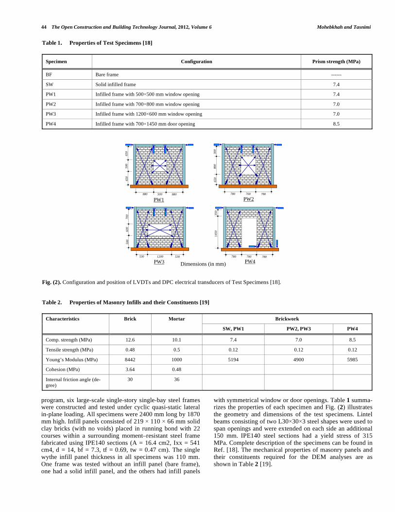
program, six large-scale single-story single-bay steel frames were constructed and tested under cyclic quasi-static lateral in-plane loading. All specimens were 2400 mm long by 1870 mm high. Infill panels consisted of 219 110 66 mm solid clay bricks (with no voids) placed in running bond with 22 courses within a surrounding moment–resistant steel frame fabricated using IPE140 sections (A = 16.4 cm2, Ixx = 541 cm4, d = 14, bf = 7.3, tf = 0.69, tw = 0.47 cm). The single wythe infill panel thickness in all specimens was 110 mm. One frame was tested without an infill panel (bare frame), one had a solid infill panel, and the others had infill panels
with symmetrical window or door openings. Table 1 summa-rizes the properties of each specimen and Fig. (2) illustrates the geometry and dimensions of the test specimens. Lintel beams consisting of two L30 30 3 steel shapes were used to span openings and were extended on each side an additional 150 mm. IPE140 steel sections had a yield stress of 315 MPa. Complete description of the specimens can be found in Ref. [18]. The mechanical properties of masonry panels and their constituents required for the DEM analyses are as shown in Table 2 [19].
Table 1. Properties of Test Specimens [18]
Specimen Configuration Prism strength (MPa)
BF Bare frame ------
SW Solid infilled frame 7.4
PW1 Infilled frame with 500 500 mm window opening 7.4
PW2 Infilled frame with 700 800 mm window opening 7.0
PW3 Infilled frame with 1200 600 mm window opening 7.0
PW4 Infilled frame with 700 1450 mm door opening 8.5
Fig. (2). Configuration and position of LVDTs and DPC electrical transducers of Test Specimens [18].
Table 2. Properties of Masonry Infills and their Constituents [19]
Brickwork Characteristics Brick Mortar
SW, PW1 PW2, PW3 PW4
Comp. strength (MPa) 12.6 10.1 7.4 7.0 8.5
Tensile strength (MPa) 0.48 0.5 0.12 0.12 0.12
Young’s Modulus (MPa) 8442 1000 5194 4900 5985
Cohesion (MPa) 3.64 0.48
Internal friction angle (de-gree)
30 36
PW1 880
650
50
0 65
0
880 500
300
80
0 65
0
780 780 700
PW2
700
60
0 50
0
530 530 1200
PW3
350
14
50
780 780 700
PW4 Dimensions (in mm)
Distinct Element Modeling of Masonry-Infilled Steel Frames The Open Construction and Building Technology Journal, 2012, Volume 6 45
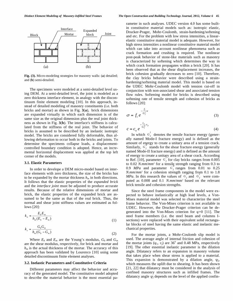
The specimens were modeled at a semi-detailed level us-ing DEM. At a semi-detailed level, the joint is modeled as a zero thickness interface element, in analogy with the discon-tinuum finite element modeling [10]. In this approach, in-stead of detailed modeling of masonry constituents (i.e. both bricks and mortar) as shown in Fig. 3(a), brick dimensions are expanded virtually in which each dimension is of the same size as the original dimension plus the real joint thick-ness as shown in Fig. 3(b). The interface's stiffness is calcu-lated from the stiffness of the real joint. The behavior of bricks is assumed to be described by an inelastic isotropic model. The bricks are considered fully deformable, thus al-lowing deformation to occur both in the bricks and joints. To determine the specimens collapse loads, a displacement-controlled boundary condition is adopted. Hence, an incre-mental horizontal displacement was applied at the top left corner of the models.
3.1. Elastic Parameters
In order to develope a DEM micro-model based on inter-face elements with zero thickness, the size of the bricks has to be expanded by the mortar thickness hm in both directions. It follows that the elastic properties of the expanded brick and the interface joint must be adjusted to produce accurate results. Because of the relative dimensions of mortar and brick, the elastic properties of the expanded brick are as-sumed to be the same as that of the real brick. Thus, the normal and shear joint stiffness values are estimated as fol-lows [20]:
)(mbm
mb
n
EEh
EEk =
(1)
)(mbm
mb
s
GGh
GGk =
(2)
Where Eb and Em are the Young’s modulus, Gb and Gm are the shear modulus, respectively, for brick and mortar and hm is the actual thickness of the mortar. The accuracy of this approach has been validated by Lourenco [10] using some detailed discontinuum finite element analyses.
3.2. Inelastic Parameters and Constitutive Criteria
Different parameters may affect the behavior and accu-racy of the generated model. The constitutive model adopted to describe the material behavior is the most essential pa-
rameter in such analyses. UDEC version 4.0 has some built-in constitutive material models such as: isotropic elastic, Drucker-Prager, Mohr-Coulomb, strain-hardening/softening and etc. For the problem with low stress intensities, a linear-elastic constitutive material model is adequate. However, for high stress intensities a nonlinear constitutive material model which can take into account nonlinear phenomena such as crack formation and crushing is required. The nonlinear post-peak behavior of stone-like materials such as masonry is characterized by softening which determines the way in which crack formation propagates within a brick [20]. It has been observed that as the shear displacement increases, the brick cohesion gradually decreases to zero [10]. Therefore, the clay bricks behavior were described using a strain-hardening/softening material model. This model is based on the UDEC Mohr-Coulomb model with tension cut-off in conjunction with non-associated shear and associated tension flow rules. Softening model for bricks is described using softening rate of tensile strength and cohesion of bricks as follows [20]:
uG
f
t
If
t
ef= (3)
pIIf
u vG
c
u ecc = (4)
In which I
fG denotes the tensile fracture energy (gener-
ally named Mode-I fracture energy) and is defined as the amount of energy to create a unitary area of a tension crack. Similarly,
II
fG stands for the shear fracture energy (generally
named Mode-II fracture energy) and is defined as the amount of energy to create a unitary area of a shear crack. According to Ref. [10], parameter
I
fG for clay bricks ranges from 0.005
to 0.02 N.mm/mm2 for a tensile strength ranging from 0.3 to 0.9 MPa and parameter
II
fG ranges from 0.01 to 0.25
N.mm/mm2 for a cohesion strength ranging from 0.1 to 1.8 MPa. In this research the values of
I
fG and
I
fG were com-
puted as 0.008 and 0.1 N.mm/mm2 based on the relevant brick tensile and cohesion strengths.
Since the steel frame components in the model were ex-pected to behave inelastically at high load levels, a Von-Mises material model was selected to characterize the steel frame behavior. The Von-Mises criterion is not available in UDEC. However, the Drucker-Prager criterion can be de-generated into the Von-Mises criterion for =0 [11]. The steel frame members (i.e. the steel beam and columns I-sections) were replaced with their equivalent solid rectangu-lar blocks of steel having the same elastic and inelastic me-chanical properties.
For the mortar joints, a Mohr-Coulomb slip model is used. The average angle of internal friction and cohesion of the mortar joints ( j, cj) are 36
o and 0.48 MPa, respectively
[19]. The other essential inelastic parameter is the dilation angle. Dilatancy refers to an expansion in masonry volume that takes place when shear stress is applied to a material. This expansion is demonstrated by a dilation angle, j, which measures the uplift due to shearing. It has been shown [21, 22] that dilatancy must be considered in the analysis of confined masonry structures such as infilled frames. The dilatancy angle j depends on the level of the applied confin-
Fig. (3). Micro-modeling strategies for masonry walls: (a) detailed;
and (b) semi-detailed.
Block MortarExpanded
block Joint
(a) (b)
Interface
46 The Open Construction and Building Technology Journal, 2012, Volume 6 Mohebkhah and Tasnimi
ing stress; as for high confining pressures (e.g. masonry infill panels) the average value of tan j
is about 0.2 [10]. There-
fore, in this paper, tangent of the dilatancy angle of 0.2 (ap-proximately j =12
o) was chosen for the joints.
The other essential parameter that must be chosen is the friction between steel members and masonry infill wall. Therefore, a coefficient of friction equal to 0.25 was as-sumed for the frame-to-infill wall interfaces [8].
4. ANALYSIS AND COMPARISON WITH TEST RE-SULTS
The 2D distinct element model generated in this study was employed to simulate the behavior of brick masonry-infilled steel frame specimens described in section 3. Fig. (4) illustrates the comparison between the load-displacement relationships of all the experimented specimens, and that of the DEM analysis, up to failure mechanism formation. The local peaks in the curves are attributed to the state at which a new joint cracking occurs or plastic failure takes place in the bricks. Also, Table 3 presents the difference between the numerical and experimental ultimate collapse loads. As it
can be seen, the experimental and numerical results compari-son shows a good correlation between them. The maximum error of the numerical analysis is 13% for speci-men PW3 and an average error of 5% for the other four specimens. The relative large difference in the load capacity value of specimen PW3 can be attributed to premature fail-ure of slender side piers in the test. In other words, the weak bricks may have induced a premature diagonal shear crack-ing failure of the slender piers leading to a low capacity.
Together with the global load-displacement relationships, a comparison in terms of the deformed geometry, displace-ment vectors and the failure mechanism is needed to investi-gate the accuracy of the DEM results. In Fig. (5), displace-ment vectors of specimen PW2 at the time of ultimate capac-ity (lateral displacement equal to 25 mm) are shown. As it is observed, lateral deformation of the infill panel takes place mainly in the side piers and the top masonry spandrel beam. The bottom masonry spandrel beam deformation is insignifi-cant and can be ignored. Therefore, it can be concluded that ductility of the infilled frame depends on the failure mode of side infill piers (i.e. force-controlled or displacement-
Fig. (4). Lateral load–displacement diagrams for all the analyzed specimens.
0
50
100
150
200
0 5 10 15 20 25
Displacement (mm)
Lo
ad (
kN)
Test
DEM
PW3
0
50
100
150
200
0 5 10 15 20 25
Displacement (mm)L
oa
d (
kN
)
Test
DEM
PW2
0
50
100
150
200
250
0 5 10 15 20 25
Displacement (mm)
Lo
ad
(k
N)
Test
DEM
PW1
0
50
100
150
200
250
0 5 10 15 20 25
Displacement (mm)
Lo
ad
(k
N)
Test
DEM
SW
0
50
100
150
0 5 10 15 20 25
Displacement (mm)
Lo
ad
(k
N)
TestDEM
PW4
Distinct Element Modeling of Masonry-Infilled Steel Frames The Open Construction and Building Technology Journal, 2012, Volume 6 47
controlled failure modes). Also, it can be observed that the effective height of right pier is less than that of the left pier. In other words, the right pier is treated as a short pier and due to the confinement by the adjacent steel beam and col-umn, it has the main role in lateral load capacity of the in-filled frame. As it is seen in Fig. (5), for DEM modeling of steel frame, the columns’ bottom has been extended down-ward. This has been done deliberately on the contrary to the test specimen. Because, it is not possible to fix the columns’ bottom in UDEC program manually; just translational dis-placements can be retrained in each node. Hence, the col-umns elongated downward additionally while restraining all the surrounding nodes, to simulate fixed boundary conditions provided in the test program. The bottom two triangles have been deleted from the whole model for this reason (restrain-ing the surrounding nodes of the column bottom). Moreover, the strong floor under the infill panel has been modeled as an elastic steel beam.
Fig. (5). Displacement vectors for specimen PW2.
The principal stresses tensor for the PW2model at ulti-mate capacity is shown in Fig. (6). In this figure, principal stresses directions show the orientation of the activated com-pressive parts orientation of the infill wall under lateral load-ing. Because of the presence of opening, the infill wall is forced to act as four distinct parts including one horizontal (top spandrel) and three inclined (side piers and bottom spandrel) compressive struts. The horizontal strut connects the windward column top to the two inclined compressive struts to resist the applied lateral load.
The state of inelastic bricks is represented using some plastic indicators in UDEC program. These indicators denote that plastic flow is occurring, but it is possible for a brick mesh element simply to sit on the yield surface without any significant flow taking place. The collapsed joints as well as the plastic behavior in the bricks are shown in Fig. (7). The failure situation of the elements is shown in this figure using three distinct symbols: , and indicating “yielding in past”, “at yield surface” and “tensile failure”, respectively. The situation “yielding in past” shows the unloaded yielding elements so that their stresses no longer satisfy the Mohr-Coulomb yield criterion [11]. As well, the situation “at yield surface” demonstrates the actively yielding elements which are important to the detection of a failure mechanism. The pattern of cracking and failure points as predicted by the numerical analysis is in good agreement with the experimen-tal observations given in [18]. Also, as shown in Fig. (7), the surrounding frame elements yield in two points (on top beam and windward column) where the activated inclined com-pressive struts interact with them. This indicates the impor-tance of short column effect that must be considered in col-umn design of such frames, especially in masonry infilled reinforced concrete frames. The experimentally obtained cracking and failure pattern of the specimen at a lateral dis-placement of 25 mm is shown in left part of Fig. (7). It is evident that the pattern of infill panel cracking and diagonal tension failure (in side piers and bottom spandrel beam) as
Table 3. Comparison of Experimental and Numerical Collapse Loads
Specimen Experimental (kN) Numerical (kN) Ratio (Num./Exp.)
SW 201.5 202 1.00
PW1 176.1 187 1.06
PW2 151.9 163 1.07
PW3 137 150 1.13
PW4 116.5 125 1.07
Fig. (6). Magnified principal stress tensors for specimen PW2 infill
panel.
48 The Open Construction and Building Technology Journal, 2012, Volume 6 Mohebkhah and Tasnimi
predicted by the DEM is compatible with laboratory experi-mental findings. The diagonal tension failure points have been distinguished from the others by the symbol . As it can be seen in the test failure pattern in Fig. (7), masonry side piers undergo sudden diagonal brittle failures (localized fracture through bricks) which cannot be properly captured by finite element-based plasticity models such as Mohr-coulomb failure criterion. That’s why the extent of DEM failure seems slightly different compared to the test. These kinds of failures can be simulated properly using fracture mechanics principles. As an alternative, the failure can be simulated in future DEM studies using the potential brick cracks as proposed by Lourenco in his PhD dissertation [10].
Fig. (8). Plot of joints with zero normal or shear stresses (joint slid-
ing).
Figs. (8) and (9) show the plot of joint sliding and joint openings in the infill panel, respectively. As can be seen, the nonlinear behavior comes from the bricks than the joints.
Fig. (10) shows the magnified picture of the deformed geometry of specimen PW2. The separations and geometry distortions of the bricks (indicating cracking and crushing of the bricks) is clearly observed in the figure. Therefore, the obtained results reveal the capacity of the DEM to model masonry infill walls behavior.
6. CONCLUSION
A 2D distinct element model developed for the inelastic nonlinear analysis of masonry-infilled steel frames. A micro-modeling approach was used to model masonry infill wall in which the joint is modeled as a zero thickness interface ele-ment. The bricks are joints are assumed fully deformable to simulate bricks failure points and joints sliding.
Fig. (9). Plot of joint opening.
Fig. (10). Magnified deformed geometry for specimen PW2 (mag-
nification factor = 10).
The developed model was used herein to simulate the lat-eral load behavior of some tested masonry-infilled steel
Fig. (7). Elements’ failure points and crack patterns of the joints for specimen PW2 (numerical and experimental [19] results).
Distinct Element Modeling of Masonry-Infilled Steel Frames The Open Construction and Building Technology Journal, 2012, Volume 6 49
frames with openings reported in the literature. It was found that the DEM model is applicable to a detailed simulation of the nonlinear behavior of such frames throughout the loading process leading to failure. The prediction of lateral load ca-pacity and the evolution of the deformations were both in agreement with the experiments. It was shown that the method can simulate confidently the failure mechanisms based on joint separation and sliding.
NOMENCLATURE
bE = Young's modulus of brick masonry
mE = Young's modulus of mortar
bG = Shear modulus of brick masonry
mG = Shear modulus of mortar
yF = Yield stress of steel material
mh = Thickness of the mortar
nk = Normal joint stiffness ( mmmmN //
2 )
sk = Shear joint stiffness ( mmmmN //
2 )
c = Brick masonry cohesion strength
= Brick masonry angle of internal friction
cf = Brick masonry compressive strength
jc = Mortar joints cohesion strength
j = Mortar joints angle of internal friction
j = Mortar joints angle of dilatancy
CONFLICT OF INTEREST
The author confirm that this article content has no con-flicts of interest.
ACKNOWLEDGEMENT
Declared none.
REFERENCES
[1] B. Stafford-Smith, “Lateral stiffness of infilled frames”, J. Struct.
Div. ASCE, vol. 88, no. ST6, pp. 183-199, 1962. [2] B. Stafford-Smith, “Behavior of square infilled frames”, J. Struct.
Div. ASCE, vol. 92, no. ST1, pp. 381-403, 1966. [3] J.R. Riddington, and B. Stafford Smith, “Analysis of infilled
frames subjected to racking with design recommendations”, Struct. Eng., vol. 55, no. 6, pp. 263-268, 1977.
[4] T.C. Liauw, and K.H. Kwan, “Unified plastic analysis for infilled frames”, J. Struct. Eng., vol. 111, no. 7, pp. 1427-1448, 1985.
[5] H.A. Moghaddam, M.G.H. Mohammadi, and M. Ghaemian, “Ex-
perimental and analytical investigation into crack strength determi-nation of infilled steel frames”, J. Construct. Steel Res., vol. 62, no.
12, pp. 1341-1352, 2006. [6] H.A. Moghaddam, and P.J. Dowling, “The state-of-the-art in in-
filled frames”, ESEE Res. Rep. No. 87-2, Imperial College of Sci-ence and Technology, Civil Engineering Department, London,
England, 1987. [7] A.B. Mehrabi, and P.B. Shing, “Finite element modeling of ma-
sonry-infilled RC frames”, J. Struct. Eng., vol. 123, no. 5, pp. 604-613, 1997.
[8] J.L. Dawe, C.K. Seah, and Y.A. Liu, “Computer model for predict-ing infilled frame behavior”, Can. J. Civ. Eng., vol. 28, pp. 133-