76
Distinctive Performance TS-590S HF/50 MHz ALL MODE TRANSCEIVER

Distinctive Performance
TS-590SHF/50 MHz ALL MODE TRANSCEIVER
Cover 2 TS-590S
This in-depth manual is intended to explain the features of the TS-590S and its convenient use. We hope that this manual, as a general HF transceiver guide will be of your benefit, to whoever reads this manual, whether you have already purchased a TS-590S, are thinking of purchasing of this product, or are interested in HF transceivers.
All copyrights and other intellectual property rights for this in-depth manual and relevant technical documents as well as the software described in this in-depth manual and relevant technical documents, and help texts and manuals attached to the software are owned by Kenwood Corporation.
A right to use the software described in this in-depth manual and relevant technical documents, and help texts and manuals attached to the software is granted to a licensee by Kenwood Corporation; however, the title to and ownership for the software shall be owned by Kenwood Corporation. Refer to this in-depth manual and relevant technical documents, and help texts and manuals attached to the software for details.
Kenwood Corporation does not warrant that quality and performance of the software described in this in-depth manual and relevant technical documents, and help texts and manuals attached to the software conform to the applicability of any use, and Kenwood Corporation shall be free from liability for any defects, damage or loss, or from any warranty for anything other than what is expressly described in this in-depth manual and relevant technical documents, and help texts and manuals attached to the software.
Any distribution, resale, lease, waiver, assignment or disclosure on a website of all in-depth manual and relevant technical documents, and help texts and manuals attached to the software written and made by Kenwood Corporation.
• Microsoft, Windows®XP, Windows Vista®, Windows®7 and Windows logo are registered trademarks of Microsoft Corporation.
• All other product names referenced herein are trademarks or registered trademarks of their respective manufacturers. ™ and ® are omitted in this manual.
The measured values exampled in this document are examples and do not guarantee the performance of the model.
ABOUT THIS MANUAL
About Copyright
Copyright of this Manual and Software
About Trademarks and Intellectual Properties
Other Restrictions

CONTENTS
1 RECEPTION ..................................... 11.1 Type of Conversion ............................11.2 Down Conversion ...............................31.3 Up Conversion....................................81.4 RX Auxiliary Circuits...........................9
2 TRANSMISSION............................. 11
2.1 Kenwood Traditional Transmitting Circuitry ............................................11
2.1.1 IF Circuits .........................................112.1.2 FET Final Circuit ...............................11
2.2 High-speed Relay-controlled Antenna Tuner..................................13
2.3 REMOTE Connector ........................132.4 DRV Terminal...................................15
3 LOCAL OSCILLATOR ................... 19
4 DSP................................................. 20
4.1 Multipurpose 32-bit Floating Point DSP..................................................20
4.2 Advanced AGC Control via IF Digital Processing........................................21
4.3 Interference Elimination Within AGC Loop .................................................23
4.3.1 Digital IF Filter ..................................234.3.2 Types of Digital IF Filters..................244.3.3 Manual Notch Filter and Auto Notch
Filter..................................................254.3.4 Digital Noise Blanker (NB2)..............26
4.4 Demodulation ...................................274.5 Modulation........................................284.6 DSP-based Auxiliary Circuits
(for RX).............................................294.6.1 Beat Cancel (AF Processing) ...........294.6.2 Noise Blanker NB2
(IF Processing) .................................304.6.3 Overview of Noise Reduction ...........314.6.4 NR1 (Spectral Subtraction Method)
(AF Processing)................................324.6.5 NR1 (Based on a Line Enhancer)
(AF Processing)................................344.6.6 NR2 (AF Processing)........................35
4.7 DSP-based Auxiliary Circuits (for TX) .............................................36
4.7.1 Speech Processor (AF Processing) ................................36
4.8 DSP-based Auxiliary Circuits (Common to TX/RX) ........................ 37
4.8.1 TX Equalizer & RX Equalizer (AF Processing) ................................37
5 SOFTWARE: ENHANCING OPERATING PLEASURE...............38
5.1 Extended Data-mode Related Functions ......................................... 38
5.2 Drive Out.......................................... 395.3 Single Button Toggles IF Filters
between A and B.............................. 405.4 Double Function Keys and Hold Time
Selection .......................................... 415.5 Mode Selection of Built-in Electronic
Keyer................................................ 415.6 Switchover of Shift Frequency
Interlocked with Change of Pitch Frequency ........................................ 41
5.7 Power-on Message .......................... 415.8 Quick Memory Function ................... 425.9 Cross Tone Function........................ 425.10 PF Keys ........................................... 425.11 Expansion of Voice Guide Function
(Optional VGS-1 Required).............. 445.12 Easy Updating of Firmware.............. 45
6 APPEARANCE DESIGN: “DESIGN CONCEPT” REVEALED BY DESIGNING ENGINEER...........46
7 STRUCTURAL FEATURES............47
7.1 Cooling............................................. 477.2 LCD.................................................. 507.3 Main Control Knob ........................... 51
8 EXPANSIVE APPLICATION SOFTWARE....................................52
8.1 Windows Related Software.............. 528.2 System Configurations..................... 52
8.2.1 Controlling TS-590S from a PC using the COM Connector..........................52
TS-590S I
CONTENTS
8.2.2 Controlling TS-590S from a PC using the USB Connector.......................... 53
8.2.3 Controlling TS-590S from a PC using the COM and ACC2 connectors (microphone and speaker connected to the PC to be used)........................... 53
8.2.4 Controlling TS-590S from a PC using the USB connector (microphone and speaker connected to the PC to be used)................................................ 53
8.2.5 Controlling TS-590S from a PC on a Remote Site ..................................... 54
8.3 New ARCP-590 (Amateur Radio Control Program for TS-590S) Freeware ..........................................54
8.3.1 Basic Specifications Inherited from ARCP-480........................................ 55
8.3.2 User Interfaces ................................ 558.3.3 KNS (Kenwood Network Command
System)............................................ 568.3.4 Visual Scan...................................... 588.3.5 Audio Equalizer................................ 58
8.4 ARHP-590 (Amateur Radio Host Program) Freeware ..........................59
8.4.1 Basic Specifications Inherited from ARHP-10.......................................... 59
8.4.2 User Interfaces ................................ 598.4.3 KNS (Kenwood Network Command
System)............................................ 608.4.4 Disabling AF Gain Control from
ARCP-590........................................ 60
8.5 New ARUA-10 (USB Audio Controller) Freeware ..........................................60
8.5.1 Basic Functions ............................... 618.5.2 Operation ......................................... 618.5.3 Setup ............................................... 618.5.4 Starting and Stopping ARUA-10 ...... 628.5.5 Adjusting Volume............................. 628.5.6 Automatic Execution when Windows
Starts ............................................... 62
8.6 New ARVP-10H (Amateur Radio VoIP Program) Freeware ..........................63
8.6.1 Basic Functions ............................... 648.6.2 Setup of ARVP-10H
(Host Station)................................... 648.6.3 Making ARVP-10H (host station)
Online or Offline............................... 648.6.4 Setup of ARVP-10R
(remote station)................................ 658.6.5 Connecting and Disconnecting
ARVP-10R (Remote Station) ........... 658.6.6 Adjusting Volume............................. 65
8.7 New Virtual COM Port Driver ...........66
9 OPTIONAL ACCESSORY ............. 67
9.1 PS-60 Regulated DC Power Supply .............................................. 67
9.2 Rectifier Circuit................................. 689.3 Switching Circuit, Constant-voltage
Circuit and Protection Circuit............ 68
II TS-590S

At the end of September, 2010, the TS-590S, a Kenwood HF band amateur radio transceiver was launched after the 7-year long silence since the releasing of TS-480S.
As implied by this model name, TS-590S is the “legitimate successor to the TS-570S”.
The product category taken over from the TS-570S by the TS-590S was created by combining the line of compact HF transceivers that was initiated by the TS-120S and inherited by TS-450S; and the line of TS-500s represented by the TS-520S that swept the market. The product is designed as a transceiver in a preferable price-to-performance range that has sufficient features and performance for the day-to-day use and that arrives with a compact size that is convenient for operations from a fixed station as well as from a mobile station for use in any fields.
One of the noteworthy planning policies is improvement of fundamental receive performance. To achieve the objective, a new structure has been employed for the front end. However, the performance of a transceiver as a whole is not determined solely by the front end. It is imperative to carefully design, in addition to the DSP and local oscillator, all the other elements including transmit performance and ease of operation in a comprehensive manner.
On the TS-590S, we have also made a drastic modification to the external appearance and we are confident it has a “face” that satisfies all HF users.
Following are the major features of the TS-590S:
Superb receive performance and astounding adjacent dynamic range characteristics• Adoption of powerful roofing filters of 500 Hz/ 2.7 kHz
(During the reception in CW, FSK and SSB modes in 1.8 MHz, 3.5 MHz, 7 MHz, 21 MHz amateur bands, and if the final passband is 2.7 kHz or less, either of the filters is automatically selected.)
• Superior C/N (carrier-to-noise ratio) thanking to the high-precision DDS (direct digital synthesizer) Substantial reduction of noise caused by unwanted adjacent signals
Adoption of a 32-bit floating point DSP to realize various functions• Advanced digital AGC control realized with DSP processing of the signal derived from the IF
stage
• A wide variety of interference removal functions including newly developed noise reductions, WIDTH/SHIFT and IF notch
High-reliability design that offers stable operation• Heavy-duty specifications for a rig enduring from continuous operation in a contest and similar
occasions
• Built-in automatic antenna tuner
• High frequency stability of ±0.5 ppm thanking to the optional SO-3 TCXO (from -10°C through +50°C or 33.8°F to 122.0°F) (The transceiver frequency is ±5ppm when the SO-3 option is not installed)
Outstanding operational ergonomics, more comfortable transmission and reception• Easy-to-use menu structure allowing excellent operability
• Large-size display equipped with the selectable LED backlight from 2 colors
• USB port that accepts not only control signals but enables input/output of transmit/receive audio signals from a PC
For details, refer to these pages providing technical explanations.
PRODUCT PLANNING OBJECTIVES
TS-590S CONTENTS I

TS-590S was planned as the “legitimate successor to the TS-570S” after 14 years or more of time have elapsed since the first market appearance of TS-570S in 1996. TS-590S is titled with the 500s model number with the TS-570S but, needless to say, we started the development as a totally new transceiver.
First, let’s look back on the TS-570S.
The product concepts of the TS-570S were “ease of operation” and “providing basic performance sufficient for rag-chewing and DX operation at a preferable price range”.
Soon after the launch of the TS-570S, the simple exterior appearance with rounded buttons stirred both positive and negative market comments, but we have received many favorable opinions from users who actually used the transceiver, such as “Buttons are easy to press” and “Setup of functions is easy to understand”.
In fact, the TS-570S employed an up-conversion circuitry configuration that was very popular at that time and provided sufficient basic performance in a transceiver having the cost-to-performance-ratio price range. The TS-570S incorporated an AF DSP, which was usually offered as an external device around that time, and received favorable reception as “a younger brother” of TS-870S that was equipped with IF DSP.
The most notable feature of the TS-590S is the superior receive performance that exceeds expectations in its the cost-to-performance-ratio price range. It goes without saying, of course, that we invested as much effort in all the other elements as in the RX circuit in developing the TS-590S.
In evaluating a transceiver, in addition to electrical characteristics represented by numerical data, ease of operation and visibility are also important criteria. As for ease of operation, Kenwood has been developing transceivers on the basis of operability of successive HF transceivers, to which users' voices also have been reflected; therefore, we need to take the history and background into consideration while designing a product.
Though the new TS-590S inherits the DNA of Kenwood’s HF transceivers, new technologies and ideas are also added. We are confident that all users, from the newest user to the most experienced veteran user, will be satisfied with this transceiver.
As for the development objectives and backdrop of the “totally new” portion of the product, we will reveal them in the technical explanations of the chapters subsequently.
Be our guest and allow us to share the development background of the TS-590S and what’s in the spirit of the development engineers.
Kenwood HF Transceiver Development Team
Development Spirit
II CONTENTS TS-590S

1 RECEPTION
Receive performance is one of the key indicators that is used to evaluate a transceiver. And, above all, the capability to protect against interference from adjacent signals close to the target signal is of the utmost importance.
To attain this goal, a circuit with a good large signal behavior characteristic is used for the first mixer of the RX section. In recent years, a filter used between the mixer and the subsequent stage (roofing filter) is also gaining much attention as a very important component.
About 30 years ago, an up-conversion circuit configuration (where the first IF is higher than the upper limit of RX frequency) appeared as an RX circuit design to provide general coverage receiving from LF through the HF band. This RX system was also adopted by amateur radio transceivers of the time to enable reception of overseas broadcasting and other signals outside amateur bands and, as a result, from that time on, almost all HF transceivers have been equipped with an up-conversion RX section.
The passband of roofing filters used in an up-conversion RX design is typically 15 to 20 kHz. However, in the case an interfering signal is only several kHz away from the target signal, the interfering signal also passes the roofing filter and the target signal is masked first in the subsequent stage. As a result, sometimes the performance of the first mixer was not extended to the best use.
That is the reason a design to switch the pass bandwidth to be 3 kHz, 6 kHz, or 15 kHz is becoming prevalent in recent transceivers. Some products can select a bandwidth as narrow as several hundred Hz and these products are very highly accepted in the market.
Meanwhile, Kenwood’s HF transceivers, which were designed 7 years ago or earlier, adopt roofing filters with a wide passband. Obviously, they still have satisfactory performance outside the pass bandwidth.
Against this backdrop, we started the development of the TS-590S by considering the circuit type that mostly focuses on the characteristics of adjacent interference elimination.
In the early stage of the TS-590S’s product development, considering the product positioning in the market, we also examined the RX design to be able to switch among the roofing filters of 3 kHz, 6 kHz and 15 kHz. However, the bandwidth of 3 kHz is too wide for CW, though it is fairly narrow for an SSB. We wanted to adopt a 500 Hz filter by all means for CW enthusiasts. However, there was a big challenge to be solved.
When it comes to the pass bandwidth of a roofing filter, at a frequency as high as 73 MHz, which is Kenwood’s mainstream first IF frequency, it is difficult to mass-produce filters with bandwidth as narrow as 500 Hz. To solve this problem, there was no other choice but to lower the first IF frequency.
After reviewing, we decided to lower the first IF to 11.374 MHz. This is called a down-conversion design. (If the receive frequency is lower than 11.374 MHz, the operation will be up conversion. However, because the first IF is lower than the highest receive frequency (60 MHz), we call the conversion type “down conversion”.)
Yet, this circuit design has a drawback. When the IF frequency that was once raised 30 years ago to provide general coverage reception is lowered again (to 8.83 MHz that was then used), images and spurious signals are produced (which are relevant not only to reception but to transmission) and these causes must be addressed one by one.
Needless to say, it is technically possible to tackle individual problems but, to do so, many additional circuits and components are required, which may result in a higher product price. In terms of market positioning, TS-590S must be a product in a competitive price range having higher cost-to-performance ratio. After examining various frequency configurations, we have selected a dual-mode conversion frequency configuration for the new TS-590S to satisfy both the performance and price requirements.
1.1 Type of Conversion
TS-590S CONTENTS 1
1 RECEPTION
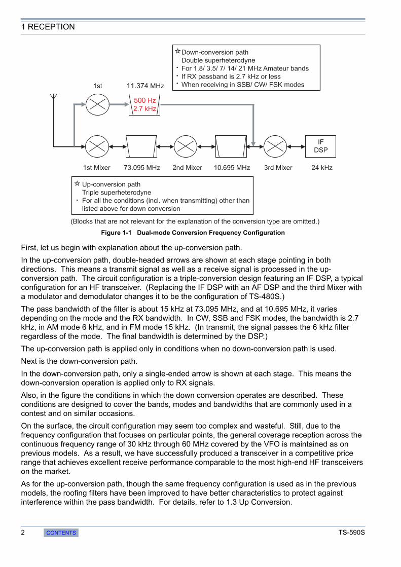
Figure 1-1 Dual-mode Conversion Frequency Configuration
First, let us begin with explanation about the up-conversion path.
In the up-conversion path, double-headed arrows are shown at each stage pointing in both directions. This means a transmit signal as well as a receive signal is processed in the up-conversion path. The circuit configuration is a triple-conversion design featuring an IF DSP, a typical configuration for an HF transceiver. (Replacing the IF DSP with an AF DSP and the third Mixer with a modulator and demodulator changes it to be the configuration of TS-480S.)
The pass bandwidth of the filter is about 15 kHz at 73.095 MHz, and at 10.695 MHz, it varies depending on the mode and the RX bandwidth. In CW, SSB and FSK modes, the bandwidth is 2.7 kHz, in AM mode 6 kHz, and in FM mode 15 kHz. (In transmit, the signal passes the 6 kHz filter regardless of the mode. The final bandwidth is determined by the DSP.)
The up-conversion path is applied only in conditions when no down-conversion path is used.
Next is the down-conversion path.
In the down-conversion path, only a single-ended arrow is shown at each stage. This means the down-conversion operation is applied only to RX signals.
Also, in the figure the conditions in which the down conversion operates are described. These conditions are designed to cover the bands, modes and bandwidths that are commonly used in a contest and on similar occasions.
On the surface, the circuit configuration may seem too complex and wasteful. Still, due to the frequency configuration that focuses on particular points, the general coverage reception across the continuous frequency range of 30 kHz through 60 MHz covered by the VFO is maintained as on previous models. As a result, we have successfully produced a transceiver in a competitive price range that achieves excellent receive performance comparable to the most high-end HF transceivers on the market.
As for the up-conversion path, though the same frequency configuration is used as in the previous models, the roofing filters have been improved to have better characteristics to protect against interference within the pass bandwidth. For details, refer to 1.3 Up Conversion.
2nd Mixer 3rd Mixer 24 kHz73.095 MHz 10.695 MHz1st Mixer
11.374 MHz
500 Hz2.7 kHz
1st
IFDSP
Down-conversion pathDouble superheterodyneFor 1.8/ 3.5/ 7/ 14/ 21 MHz Amateur bandsIf RX passband is 2.7 kHz or lessWhen receiving in SSB/ CW/ FSK modes
Up-conversion pathTriple superheterodyneFor all the conditions (incl. when transmitting) other than listed above for down conversion
(Blocks that are not relevant for the explanation of the conversion type are omitted.)
2 CONTENTS TS-590S

1 RECEPTION
Figure 1-2 Block diagram: Down Conversion
Figure 1-2 describes the circuit configuration around the first mixer of the down-conversion path, showing the relationships between frequencies upon receipt of a 14 MHz signal.
The signal from the antenna passes the RF BPF or LPF (as a receive LPF, it divides the frequency band of 30 kHz to 60 MHz into 12 ranges) and RF Amp (or bypasses it) to be sent into the first mixer. Because in the first mixer section, a different mixer is used for the up conversion and down conversion respectively, the suitable mixer is selected according to the conditions.
Figure 1-3 Receiver Mixer Circuit
1.2 Down Conversion
TS-590S CONTENTS 3

1 RECEPTION
The receiver mixer circuit is a quad mixer consisting of four 2SK1740 JFETs.
The mixer circuit achieves superior characteristics thanks to the revision of I/O port matching and the optimization of biases.
With the signal provided by the first local oscillator, the RX signal is converted to 11.374 MHz (first IF frequency).
The converted RX signal passes the first roofing filter of pass bandwidth 6 kHz and in the subsequent stage the signal is moderately amplified by the post amplifier, and sent into the second roofing filter. Part of the signal is also sent to the noise blanker.
The role of the first roofing filer is to limit the bandwidth for the sake of the noise blanker. We have selected a pass bandwidth of 6 kHz that does not affect pulse noise. Besides, by setting the intercept point of the post amplifier higher than that of the mixer, the deterioration of the two-tone characteristics is minimized within the pass bandwidth.
For second roofing filters, two 6-pole MCFs of 500 Hz and of 2.7 kHz respectively are equipped as standard at the time of purchase of your transceiver. Which filter is used is automatically determined according to the final pass bandwidth, i.e. depending on the conditions including the bandwidth selection made with WIDTH or LO CUT/ HI CUT controls on the front panel.
For example, in CW or FSK mode, if WIDTH is 500 Hz or less, the 500 Hz filter is selected and if WIDTH is 600 Hz or more, 2.7 kHz filter is selected. In SSB mode, if the difference between the HI CUT and LO CUT frequencies is 2.7 kHz or less, the 2.7 kHz filter is selected and if the combination produces exceeds a difference of 2.7 kHz, the up-conversion path is automatically applied. (In SSB-DATA mode, if WIDTH is 500 Hz or less, the 500 Hz filter is selected.)
In AM and FM modes, because the pass bandwidth of the down conversion path is too narrow, the signal is received with the up conversion path.
These operations are used in the amateur radio bands of 1.8 MHz, 3.5 MHz, 7 MHz, 14 MHz and 21 MHz, and for other amateur radio bands including WRC bands, and for other frequency ranges of general coverage receiving, up conversion is used regardless of the mode and pass bandwidth. (Since this switchover is determined by the CPU taking various conditions into its criteria, the conversion path cannot manually be selected.)
Figure 1-4 MCF
Figure 1-4 is an image of MCFs. From left to right, there is the 500 Hz filter at 11.374 MHz that is used in down conversion and next is the 2.7 kHz filter at 11.374 MHz.
At the rightmost filter is the 2.7 kHz filter at 10.695 MHz that is used during the up-conversion.
4 CONTENTS TS-590S

1 RECEPTION
• During the transmission:
The up-conversion configuration is always used in all modes and bandwidths. During the transmission in SSB mode, the pass bandwidth is determined by the filter settings (digital filter of the DSP) selected in the menu mode. The pass bandwidth of the filter in the analog stage is 6 kHz and does not affect the final outcome of the frequency analysis.
• During the reception in AM or FM mode:
The up-conversion configuration is always used regardless of the frequency or pass bandwidth settings.
• If WIDTH is switched from 500 Hz to 600 Hz during the reception in the 3.5 MHz band in CW mode:
While the down conversion configuration is maintained, the roofing filter is switched from 500 Hz to 2.7 kHz.
• LO CUT is changed to 200 Hz when receiving in the 14 MHz band in SSB mode with LO CUT 300 Hz and HI CUT 3000 Hz:
Because the final pass bandwidth exceeds 2.7 kHz, the operation is switched from down-conversion to up-conversion configuration.
• During the reception in the 50 MHz band in SSB mode with LO CUT 300 Hz and HI CUT 2700 Hz:
The up-conversion configuration is used. Though the pass bandwidth of the roofing filter is 15 kHz, the 2.7 kHz filter is selected at the second IF of 10.695 MHz.
Table 1-1 Combination of Filters at Conversion
Hints and Tips “Which type of conversion is used?”
Conversion Type
Analog IF filterFrequency Setting
ConditionsSetting Example
FrequencyPass
Bandwidth
Down conversion (in 1.8 MHz, 3.5 MHz, 7 MHz, 14 MHz and 21 MHz
bands and if BW is no more than 2700 Hz)
11.374 MHz (first IF)
500 Hz BW is no more than 500 Hz7.005 MHz/ CW WIDTH:
250 Hz
2.7 kHzBW is between 550 Hz and
2700 Hz14.175 MHz/ USB LO:
100 Hz, HI 2800 Hz
Up conversion (in other than above conditions)
10.695 MHz (second IF)
2.7 kHz BW is no more than 2700 Hz28.250 MHz/ USB LO: 100 Hz, HI: 2800 Hz
6 kHzSSB BW is between 2750 Hz
and 5000 Hz/AM HI CUT between 2.5 kHz and 3 kHz
3.560 MHz/ LSB LO: 50 Hz, HI: 3000 Hz
15 kHzAM HI CUT is between 4 kHz
and 5 kHz*1/ FM*1 In AM mode, the bandwidth at the IF stage is equal to the value as double as the value for HI CUT frequency at the AF stage.
50.550 MHz/ AM LO: 100 Hz, HI: 4000 Hz
TS-590S CONTENTS 5
1 RECEPTION
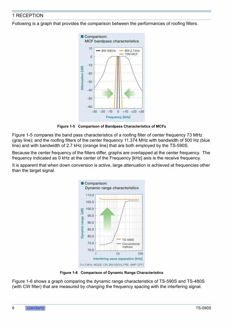
Following is a graph that provides the comparison between the performances of roofing filters.
Figure 1-5 Comparison of Bandpass Characteristics of MCFs
Figure 1-5 compares the band pass characteristics of a roofing filter of center frequency 73 MHz (gray line); and the roofing filters of the center frequency 11.374 MHz with bandwidth of 500 Hz (blue line) and with bandwidth of 2.7 kHz (orange line) that are both employed by the TS-590S.
Because the center frequency of the filters differ, graphs are overlapped at the center frequency. The frequency indicated as 0 kHz at the center of the Frequency [kHz] axis is the receive frequency.
It is apparent that when down conversion is active, large attenuation is achieved at frequencies other than the target signal.
Figure 1-6 Comparison of Dynamic Range Characteristics
Figure 1-6 shows a graph comparing the dynamic range characteristics of TS-590S and TS-480S (with CW filter) that are measured by changing the frequency spacing with the interfering signal.
6 CONTENTS TS-590S
1 RECEPTION
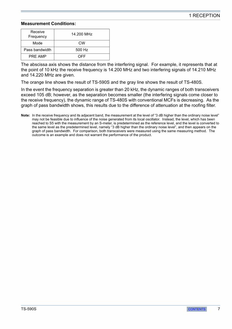
Measurement Conditions:
The abscissa axis shows the distance from the interfering signal. For example, it represents that at the point of 10 kHz the receive frequency is 14.200 MHz and two interfering signals of 14.210 MHz and 14.220 MHz are given.
The orange line shows the result of TS-590S and the gray line shows the result of TS-480S.
In the event the frequency separation is greater than 20 kHz, the dynamic ranges of both transceivers exceed 105 dB; however, as the separation becomes smaller (the interfering signals come closer to the receive frequency), the dynamic range of TS-480S with conventional MCFs is decreasing. As the graph of pass bandwidth shows, this results due to the difference of attenuation at the roofing filter.
Note: In the receive frequency and its adjacent band, the measurement at the level of “3 dB higher than the ordinary noise level” may not be feasible due to influence of the noise generated from its local oscillator. Instead, the level, which has been reached to S5 with the measurement by an S-meter, is predetermined as the reference level, and the level is converted to the same level as the predetermined level, namely “3 dB higher than the ordinary noise level”, and then appears on the graph of pass bandwidth. For comparison, both transceivers were measured using the same measuring method. The outcome is an example and does not warrant the performance of the product.
Receive Frequency
14.200 MHz
Mode CW
Pass bandwidth 500 Hz
PRE AMP OFF
TS-590S CONTENTS 7
1 RECEPTION
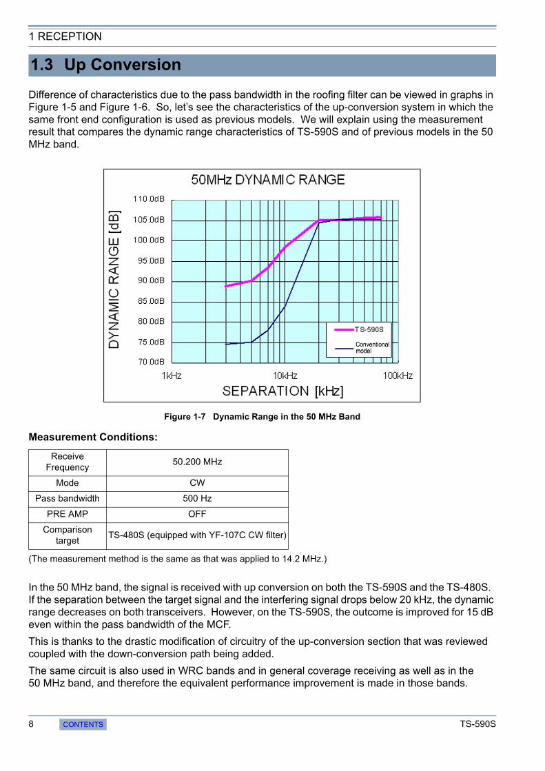
Difference of characteristics due to the pass bandwidth in the roofing filter can be viewed in graphs in Figure 1-5 and Figure 1-6. So, let’s see the characteristics of the up-conversion system in which the same front end configuration is used as previous models. We will explain using the measurement result that compares the dynamic range characteristics of TS-590S and of previous models in the 50 MHz band.
Figure 1-7 Dynamic Range in the 50 MHz Band
Measurement Conditions:
(The measurement method is the same as that was applied to 14.2 MHz.)
In the 50 MHz band, the signal is received with up conversion on both the TS-590S and the TS-480S. If the separation between the target signal and the interfering signal drops below 20 kHz, the dynamic range decreases on both transceivers. However, on the TS-590S, the outcome is improved for 15 dB even within the pass bandwidth of the MCF.
This is thanks to the drastic modification of circuitry of the up-conversion section that was reviewed coupled with the down-conversion path being added.
The same circuit is also used in WRC bands and in general coverage receiving as well as in the 50 MHz band, and therefore the equivalent performance improvement is made in those bands.
1.3 Up Conversion
Receive Frequency
50.200 MHz
Mode CW
Pass bandwidth 500 Hz
PRE AMP OFF
Comparison target
TS-480S (equipped with YF-107C CW filter)
8 CONTENTS TS-590S

1 RECEPTION
Typical built-in RX auxiliary circuits include the variable pass bandwidth circuit, notch filter and noise blanker (NB). In modern HF transceivers, most of these auxiliary circuits (=auxiliary functions) are made possible by an arithmetic process of the DSP. As well as the TS-590S, only two auxiliary circuits operate genuinely at the IF stage: NB and AGC (ATT circuit that functions by receiving the control signal provided by the DSP).
On the TS-590S, there are two methods available to achieve noise blanking: NB1 and NB2. NB1 is realized by analog processing and NB2 by digital processing of the IF DSP. Still retaining an analog noise blanker, TS-590S may seem out of step with the times. But it is critical to have an analog noise blanker for a receiving system design using narrow roofing filters.
Noise is typically pulse-shaped and when the noise passes a narrow filter, the pulse waveform is changed to have a wider (longer) pulse width.
Within the DSP, the processing block of the noise blanker is placed in a stage earlier than the filter block that determines the final pass bandwidth. Thus, even if the final pass bandwidth is narrowed, the blanking operation can work properly, free of the influence of the narrowed bandwidth.
However, roofing filters are located far earlier than the DSP, in the later stage of the first mixer. As a result, in the event the bandwidth of the roofing filter becomes as narrow as 500 Hz, the pulse width becomes wider and a conventional digital noise blanker would not deliver a sufficient blanking effect.
This is the exact case while down conversion is active on the TS-590S and a digital noise blanker alone may not produce a great enough effect. That is the reason we have placed a filter of pass bandwidth 6 kHz right after the first mixer. The filter deters the transformation of the pulse shape and prevents false operation of the noise blanker due to adjacent signals while sending the noise signals to the analog noise blanker.
During the up conversion, the noise signal is derived from the second IF stage and delivered to the noise blanker circuit as in previous models.
NB1and NB2 are the name of the functions that have been used in TS-930S and all subsequent products. NB2 was especially designed to have a blanking effect against noise with a long pulse width and a long period that has been known as the “Woodpecker.” After the woodpecker noise disappeared, the NB2 function was not employed, but in recent years a new breed of noise called the “China Dragon” has appeared. So, there may be cases when NB1 alone may not have a great enough effect on the China Dragon, NB2 has been spotlighted again. Note, however, NB2 on the TS-590S is realized with digital processing and, thereafter, totally different from NB2 in the TS-930S era.
As explained above, while the narrow bandwidth of the roofing filter is employed, the noise blanker of the DSP cannot have a sufficient effect. However, the NB2 realized with the DSP on the TS-590S turns out to be unexpectedly effective in many occasions, even while the bandwidth is less than 500 Hz in CW mode. This is because the new NB2 can fully adjust the blanking time to the length of the pulse.
NB2 of the TS-590S is most effective when you want to pick up a weak signal that is almost buried in the noise with a long pulse width that cannot be eliminated by NB1. Try NB2 in such occasions and be surprised.
On the TS-590S, by changing the circuitry configuration inside the transceiver, you can change the sensitivity in the BC band and the attenuation amount of the [ATT] key on the front panel.
1.4 RX Auxiliary Circuits
Hints and Tips “What are NB1 and NB2?”
Hints and Tips “Improvement of sensitivity in the BC band and alteration in ATT attenuation”
TS-590S CONTENTS 9

1 RECEPTION
Following is a figure that represents the TX-RX UNIT that has the circuitry configuration in question. By detaching the lower case, you can access the jumper connectors CN101 through CN103.
Figure 1-8 TX-RX UNIT
1) Raising sensitivity in the BC band:
Remove the jumper for CN103 and insert the jumper into CN102. This will increase the sensitivity in the BC band for 20 dB. (Assuming that there is the high output power in local broadcasting stations in the BC band, the sensitivity is lowered by 20 dB as the is factory default.)
2) Changing the attenuation amount of ATT:
Remove the jumper of CN101. This changes the attenuation of ATT from 12 dB to 20 dB. (Store the removed jumper in a secure place for future use.)
The headphone jack of the TS-590S is designed to have, as on the previous HF transceivers, an impedance of 8 (standard). Therefore, if you use a headphone with impedance higher than 8, you will experience the symptoms as below.
• The volume level is too high overall.
• Even if AF Volume is turned down, a hissing residual noise is audible.
• Even if the beep sound level is set to minimum, the beep sound is loud.
If you experience these symptoms, use a set of headphones with impedance close to 8.
Hints and Tips “The output level of the headphone jack is too high?”
CN101
CN102
CN103
10 CONTENTS TS-590S

2 TRANSMISSION
The tradition of high quality audio technology that users rely on Kenwood to deliver is produced by combining analog and digital technologies that Kenwood has nurtured thus far. The DSP controls modulation and determines the sound quality and analog circuits convey and amplify the signal cleanly.
The first IF transmit signal that is output at 24 kHz from the DSP and the DA converter is converted to 10.695 MHz in a dedicated IC for the mixer. The second IF signal at 10.695 MHz passes an IF filter of 6 kHz bandwidth at which undesired frequency components outside the pass bandwidth are attenuated before the signal is amplified. Then, the second IF signal passes to the ALC circuit that controls the output power to a stable level. After that, the signal goes through the gain control circuit that corrects the minutely small differences in gain from band to band, and the signal enters the mixer that is commonly used in TX and RX, and is converted to the third IF of 73.095 MHz. The signal passes the gain control circuit that adjusts the signal to the necessary gain level according to the specified power level. Then, the signal passes the filter that eliminates spurious components before going into the mixer circuit that converts the signal to the desired transmit frequency. Also, delicate gain control is done, such as decreasing the gain of the amplifier while the key is not depressed in CW mode. By means of these processes, a high-quality transmit signal with low noise can be acquired. The signal converted to the desired transmit frequency passes the BPF for removing spurious signals to prevent from generating interfering signals outside of the transmit bandwidth, and is amplified to a prescribed level before being sent to the final circuit. The drive signal produced here can be extracted from the DRV terminal. (While the output from DRV is selected.)
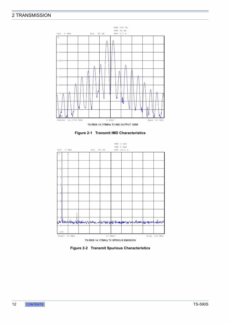
The final amplifier of the TS-590S is a push-pull amplifier using two pieces of RD100HHF1 MOSFET from Mitsubishi Electric Semiconductor (Pch 176.5 W). The drive amplifier also uses an RD100HHF1 MOSFET and the pre-drive amplifier employs an RD06HHF1 MOSFET and they, despite being 13.8V final circuits, amplify the signal reasonably in a stable and continuous manner with low distortion. Figure 2-1 shows the graph of IMD characteristics and Figure 2-2 shows the graph of harmonic spurious characteristics. Superior distortion characteristics and clean signals are acquired in this way.
2.1 Kenwood Traditional Transmitting Circuitry
2.1.1 IF Circuits
2.1.2 FET Final Circuit
TS-590S CONTENTS 11
2 TRANSMISSION
Figure 2-1 Transmit IMD Characteristics
Figure 2-2 Transmit Spurious Characteristics
12 CONTENTS TS-590S

2 TRANSMISSION
TS-590S has a built-in high-speed relay-controlled antenna tuner that was first employed in the TS-570S. In contrast to the variable capacitor type antenna tuner, it employs a small and lightweight relay to achieve a sufficient matching range and a fast tuning operation with digital control. The control speed has been further accelerated over previous models. When you return to a previously used operating band or frequency, the antenna tuner easily and quickly re-tunes.
The transceiver has a REMOTE connector that has the same pin assignment and specifications as on previous models.
Pin 6 is the ALC terminal. When you use a linear amplifier or transverter, we recommend you connect the external accessory device to the ALC terminal in order to control the output to be within an appropriate range.
The ALC signal is a signal to shift the voltage in the minus direction (in Kenwood’s devices) when the output level requires regulation to satisfy the requirements of the external accessory device. Generally external accessory devices have a VR for adjusting the voltage. In the TS-590S, a negative voltage (approximately -10 V) is applied to the ALC terminal to decrease the internal gain.
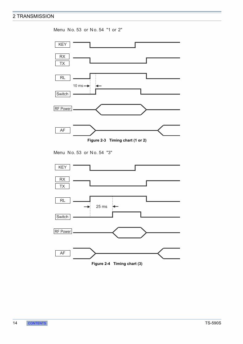
As well, for the purpose of controlling a linear amplifier and other external device, the transceiver is equipped with a relay output terminal and an RL terminal (Pin 7) to which an approximately 12 V voltage is output. The relay output and RL terminal output are coordinated with internal controls and can be adjusted in the linear amplifier control setting menu No. 53 (HF bands) or No. 54 (50 MHz band). Table 2-1 describes the possible settings of the menu, and Figure 2-3 and Figure 2-4 provide the timing charts.
If using equipment that is not designed for full break-in and requires a delay for internal switchover, such as TL-922, select “3”. In this way, you can increase the delay between the case when the transceiver is switched to transmit and the case when the signal is actually sent out. Note; however, if the full break-in setting is selected in CW mode (and if the delay time is set to “FBK”), the transmit start time cannot be delayed.
Table 2-1 Setting Menu of Linear Amplifier Control
2.2 High-speed Relay-controlled Antenna Tuner
2.3 REMOTE Connector
Linear Amplifier Controls
SettingControl of Linear
Amplifier (RL terminal)Control of Relay (COM/
BRK/MKE terminals)Transmit Start Delay Time
OFF OFF OFF 10 ms
1 ON OFF 10 ms
2 ON ON 10 ms
3 ON ON 25 ms
TS-590S CONTENTS 13
2 TRANSMISSION
Figure 2-3 Timing chart (1 or 2)
Figure 2-4 Timing chart (3)
Menu N o. 53 or N o. 54 "1 or 2"
10 ms
KEY
RX
RL
Switch
RF Power
AF
TX
Menu N o. 53 or N o. 54 "3"
25 ms
Switch
RF Power
AF
KEY
RX
RL
TX
14 CONTENTS TS-590S

2 TRANSMISSION
TS-590S is equipped with a DRV terminal that formerly was provided only for high-end transceivers.
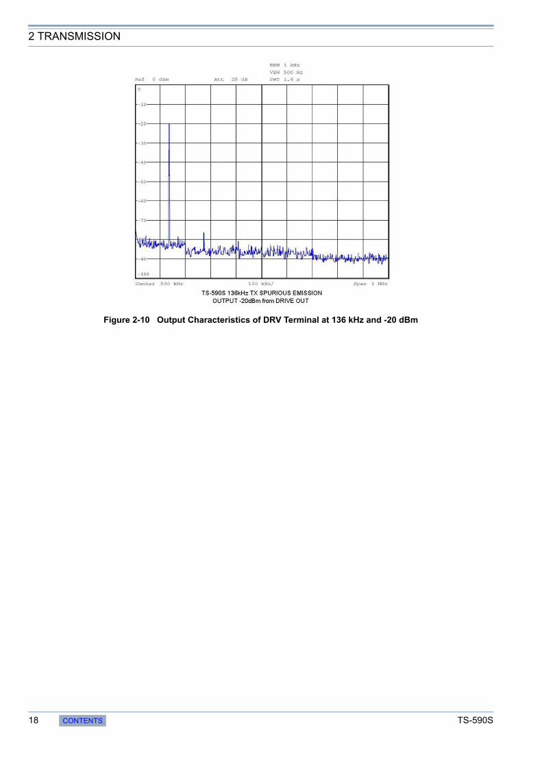
The output level of the DRV terminal is about 0 dBm (1 mW) and can be decreased to around 1/20 depending on the setting of the transmit power. To reduce the output level further, you can adjust the transmit power also by the carrier level in CW, FSK and AM modes or by the microphone gain or processor output level in SSB mode. The output level of the signal from the terminal is too low to be transmitted as is, but by connecting a high-gain linear amplifier, the signal can be used for operation in the 135 kHz band or for operation with a transverter. Figure 2-5 through Figure 2-7 show the spurious characteristics when using the signal from the DRV terminal in the 14 MHz band and Figure 2-8 through Figure 2-10 show the spurious characteristics in the 135 kHz band. If the output level is 0 dBm in the 135 kHz band, the harmonics increase slightly; therefore, you need to place an LPF after the amplifier or in some other way eliminate the harmonics. Also, lowering the setting of the transmit output level or limiting the output level at the DRV terminal by entering the ALC signal will also contribute to reduce distortion.
Figure 2-5 Output Characteristics of DRV Terminal at 14.175 MHz and 0 dBm
2.4 DRV Terminal
TS-590S CONTENTS 15

2 TRANSMISSION
Figure 2-6 Output Characteristics of DRV Terminal at 14.175 MHz and -10 dBm
Figure 2-7 Output Characteristics of DRV Terminal at 14.175 MHz and -20 dBm
16 CONTENTS TS-590S

2 TRANSMISSION
Figure 2-8 Output Characteristics of DRV Terminal at 136 kHz and 0 dBm
Figure 2-9 Output Characteristics of DRV Terminal at 136 kHz and -10 dBm
TS-590S CONTENTS 17
2 TRANSMISSION
Figure 2-10 Output Characteristics of DRV Terminal at 136 kHz and -20 dBm
18 CONTENTS TS-590S
3 LOCAL OSCILLATOR
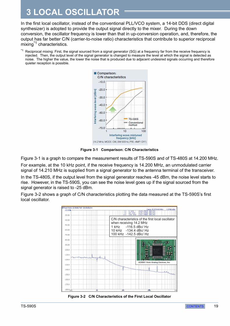
In the first local oscillator, instead of the conventional PLL/VCO system, a 14-bit DDS (direct digital synthesizer) is adopted to provide the output signal directly to the mixer. During the down conversion, the oscillator frequency is lower than that in up-conversion operation, and, therefore, the output has far better C/N (carrier-to-noise ratio) characteristics that contribute to superior reciprocal mixing*1 characteristics.*1 Reciprocal mixing: First, the signal sourced from a signal generator (SG) at a frequency far from the receive frequency isinjected. Then, the output level of the signal generator is changed to measure the level at which the signal is detected as noise. The higher the value, the lower the noise that is produced due to adjacent undesired signals occurring and therefore quieter reception is possible.
Figure 3-1 Comparison: C/N Characteristics
Figure 3-1 is a graph to compare the measurement results of TS-590S and of TS-480S at 14.200 MHz.
For example, at the 10 kHz point, if the receive frequency is 14.200 MHz, an unmodulated carrier signal of 14.210 MHz is supplied from a signal generator to the antenna terminal of the transceiver.
In the TS-480S, if the output level from the signal generator reaches -45 dBm, the noise level starts to rise. However, in the TS-590S, you can see the noise level goes up if the signal sourced from the signal generator is raised to -25 dBm.
Figure 3-2 shows a graph of C/N characteristics plotting the data measured at the TS-590S’s first local oscillator.
Figure 3-2 C/N Characteristics of the First Local Oscillator
C/N characteristics of the first local oscillator when receiving 14.2 MHz1 kHz -116.5 dBc/ Hz10 kHz -134.4 dBc/ Hz100 kHz -142.5 dBc/ Hz
TS-590S CONTENTS 19
4 DSP
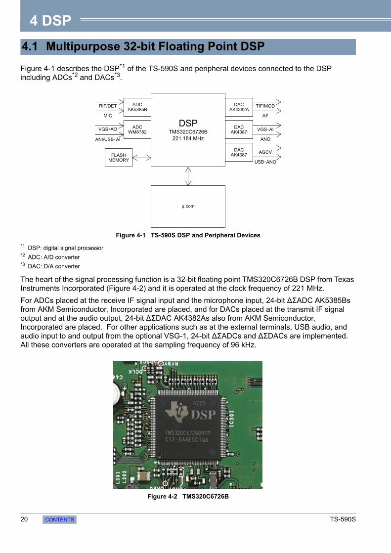
Figure 4-1 describes the DSP*1 of the TS-590S and peripheral devices connected to the DSP including ADCs*2 and DACs*3.
Figure 4-1 TS-590S DSP and Peripheral Devices
*1 DSP: digital signal processor*2 ADC: A/D converter*3 DAC: D/A converter
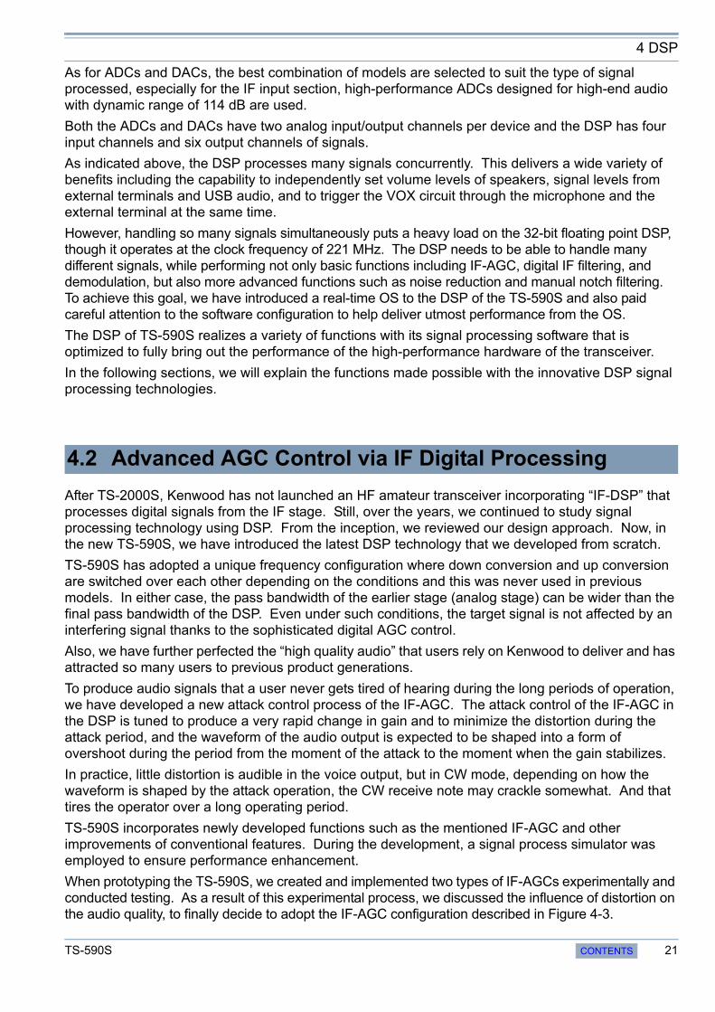
The heart of the signal processing function is a 32-bit floating point TMS320C6726B DSP from Texas Instruments Incorporated (Figure 4-2) and it is operated at the clock frequency of 221 MHz.
For ADCs placed at the receive IF signal input and the microphone input, 24-bit ΔΣADC AK5385Bs from AKM Semiconductor, Incorporated are placed, and for DACs placed at the transmit IF signal output and at the audio output, 24-bit ΔΣDAC AK4382As also from AKM Semiconductor, Incorporated are placed. For other applications such as at the external terminals, USB audio, and audio input to and output from the optional VSG-1, 24-bit ΔΣADCs and ΔΣDACs are implemented. All these converters are operated at the sampling frequency of 96 kHz.
Figure 4-2 TMS320C6726B
4.1 Multipurpose 32-bit Floating Point DSP
ADCAK5385B
DACAK4382A
DACAK4387
DACAK4387
ADCWM8782
FLASHMEMORY
VGS AO
MIC
RIF/DET
ANI/USB AI
µ com
AF
TIF/MOD
ANO
VGS AI
USB ANO
AGCV
DSPTMS320C6726B
221.184 MHz
20 CONTENTS TS-590S
4 DSP
As for ADCs and DACs, the best combination of models are selected to suit the type of signal processed, especially for the IF input section, high-performance ADCs designed for high-end audio with dynamic range of 114 dB are used.
Both the ADCs and DACs have two analog input/output channels per device and the DSP has four input channels and six output channels of signals.
As indicated above, the DSP processes many signals concurrently. This delivers a wide variety of benefits including the capability to independently set volume levels of speakers, signal levels from external terminals and USB audio, and to trigger the VOX circuit through the microphone and the external terminal at the same time.
However, handling so many signals simultaneously puts a heavy load on the 32-bit floating point DSP, though it operates at the clock frequency of 221 MHz. The DSP needs to be able to handle many different signals, while performing not only basic functions including IF-AGC, digital IF filtering, and demodulation, but also more advanced functions such as noise reduction and manual notch filtering. To achieve this goal, we have introduced a real-time OS to the DSP of the TS-590S and also paid careful attention to the software configuration to help deliver utmost performance from the OS.
The DSP of TS-590S realizes a variety of functions with its signal processing software that is optimized to fully bring out the performance of the high-performance hardware of the transceiver.
In the following sections, we will explain the functions made possible with the innovative DSP signal processing technologies.
After TS-2000S, Kenwood has not launched an HF amateur transceiver incorporating “IF-DSP” that processes digital signals from the IF stage. Still, over the years, we continued to study signal processing technology using DSP. From the inception, we reviewed our design approach. Now, in the new TS-590S, we have introduced the latest DSP technology that we developed from scratch.
TS-590S has adopted a unique frequency configuration where down conversion and up conversion are switched over each other depending on the conditions and this was never used in previous models. In either case, the pass bandwidth of the earlier stage (analog stage) can be wider than the final pass bandwidth of the DSP. Even under such conditions, the target signal is not affected by an interfering signal thanks to the sophisticated digital AGC control.
Also, we have further perfected the “high quality audio” that users rely on Kenwood to deliver and has attracted so many users to previous product generations.
To produce audio signals that a user never gets tired of hearing during the long periods of operation, we have developed a new attack control process of the IF-AGC. The attack control of the IF-AGC in the DSP is tuned to produce a very rapid change in gain and to minimize the distortion during the attack period, and the waveform of the audio output is expected to be shaped into a form of overshoot during the period from the moment of the attack to the moment when the gain stabilizes.
In practice, little distortion is audible in the voice output, but in CW mode, depending on how the waveform is shaped by the attack operation, the CW receive note may crackle somewhat. And that tires the operator over a long operating period.
TS-590S incorporates newly developed functions such as the mentioned IF-AGC and other improvements of conventional features. During the development, a signal process simulator was employed to ensure performance enhancement.
When prototyping the TS-590S, we created and implemented two types of IF-AGCs experimentally and conducted testing. As a result of this experimental process, we discussed the influence of distortion on the audio quality, to finally decide to adopt the IF-AGC configuration described in Figure 4-3.
4.2 Advanced AGC Control via IF Digital Processing
TS-590S CONTENTS 21
4 DSP
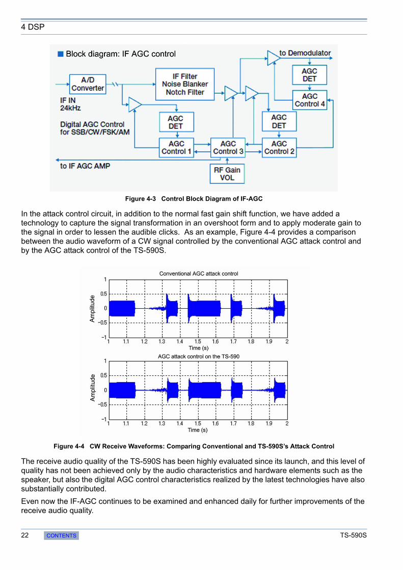
Figure 4-3 Control Block Diagram of IF-AGC
In the attack control circuit, in addition to the normal fast gain shift function, we have added a technology to capture the signal transformation in an overshoot form and to apply moderate gain to the signal in order to lessen the audible clicks. As an example, Figure 4-4 provides a comparison between the audio waveform of a CW signal controlled by the conventional AGC attack control and by the AGC attack control of the TS-590S.
Figure 4-4 CW Receive Waveforms: Comparing Conventional and TS-590S’s Attack Control
The receive audio quality of the TS-590S has been highly evaluated since its launch, and this level of quality has not been achieved only by the audio characteristics and hardware elements such as the speaker, but also the digital AGC control characteristics realized by the latest technologies have also substantially contributed.
Even now the IF-AGC continues to be examined and enhanced daily for further improvements of the receive audio quality.
22 CONTENTS TS-590S
4 DSP
TS-590S also incorporates rich and powerful interference elimination functions that work within the IF-AGC loop (Figure 4-3).
The previous model (TS-2000S) already featured a digital IF filter and the auto notch filter function, and in the TS-590S, a digital noise blanker (NB2) and a manual notch filter function*1 have been added.
These functions within the AGC loop eliminate interference to make a weak target signal emerge clearly.*1 The auto notch filter and manual notch filter cannot be used at the same time.
The digital IF filter of the TS-590S consists of slope tuning combining an IIR (infinite impulse response) LPF and an IIR HPF in SSB mode, of WIDTH/SHIFT using an IIR BPF in CW, FSK and SSB-DATA modes, and of an FIR (finite impulse response) BPF in AM mode. (In FM mode, since an FM detection IC is used, the signal at the IF stage is not processed by the DSP. Instead, the demodulated audio signal is processed by an AF filter.)
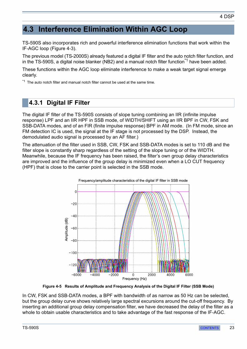
The attenuation of the filter used in SSB, CW, FSK and SSB-DATA modes is set to 110 dB and the filter slope is constantly sharp regardless of the setting of the slope tuning or of the WIDTH. Meanwhile, because the IF frequency has been raised, the filter’s own group delay characteristics are improved and the influence of the group delay is minimized even when a LO CUT frequency (HPF) that is close to the carrier point is selected in the SSB mode.
Figure 4-5 Results of Amplitude and Frequency Analysis of the Digital IF Filter (SSB Mode)
In CW, FSK and SSB-DATA modes, a BPF with bandwidth of as narrow as 50 Hz can be selected, but the group delay curve shows relatively large spectral excursions around the cut-off frequency. By inserting an additional group delay compensation filter, we have decreased the delay of the filter as a whole to obtain usable characteristics and to take advantage of the fast response of the IF-AGC.
4.3 Interference Elimination Within AGC Loop
4.3.1 Digital IF Filter
TS-590S CONTENTS 23

4 DSP
Figure 4-6 Results of Amplitude and Frequency Analysis of the Digital IF Filter (CW Mode)0 Hz in the center that corresponds to the pitch frequency
The following table provides possible choices of the filters and the default value (shown in bold) for respective modes.
4.3.2 Types of Digital IF Filters
SSB Mode
LOW CUT0 Hz, 50 Hz, 100 Hz, 200 Hz, 300 Hz, 400 Hz, 500 Hz, 600 Hz, 700 Hz, 800 Hz, 900 Hz, 1000 Hz
HI CUT1.0 kHz, 1.2 kHz, 1.4 kHz, 1.6 kHz, 1.8 kHz, 2.0 kHz, 2.2 kHz, 2.4 kHz, 2.6 kHz, 2.8 kHz, 3.0 kHz, 3.4 kHz, 4.0 kHz, 5.0 kHz
CW ModeWIDTH
50 Hz, 80 Hz, 100 Hz, 150 Hz, 200 Hz, 250 Hz, 300 Hz, 400 Hz, 500 Hz, 600 Hz, 1000 Hz, 1500 Hz, 2000 Hz, 2500 Hz
SHIFT Between 300 Hz and 1 kHz (in steps of 50 Hz), default value 800 Hz
SSB-DATA Mode
WIDTH50 Hz, 80 Hz, 100 Hz, 150 Hz, 200 Hz, 250 Hz, 300 Hz, 400 Hz, 500 Hz, 600 Hz, 1000 Hz, 1500 Hz, 2000 Hz, 2500 Hz
SHIFT1000 Hz, 1100 Hz, 1200 Hz, 1300 Hz, 1400 Hz, 1500 Hz, 1600 Hz, 1700 Hz, 1800 Hz, 1900 Hz, 2000 Hz, 2100 Hz, 2210 Hz
AM mode (LOW CUT filters are AF filters)
LOW CUT 0 Hz, 100 Hz, 200 Hz, 300 Hz
HI CUT 2.5 kHz, 3.0 kHz, 4.0 kHz, 5.0 kHz
FSK Mode WIDTH 250 Hz, 500 Hz, 1000 Hz, 1500 Hz
FM mode (AF filters)
LOW CUT0 Hz, 50 Hz, 100 Hz, 200 Hz, 300 Hz, 400 Hz, 500 Hz, 600 Hz, 700 Hz, 800 Hz, 900 Hz, 1000 Hz
HI CUT1.0 kHz, 1.2 kHz, 1.4 kHz, 1.6 kHz, 1.8 kHz, 2.0 kHz, 2.2 kHz, 2.4 kHz, 2.6 kHz, 2.8 kHz, 3.0 kHz, 3.4 kHz, 4.0 kHz, 5.0 kHz
24 CONTENTS TS-590S

4 DSP
The manual notch filter is a notch filter with a frequency that can be shifted with the notch knob. The auto notch filter is a notch filter that automatically tracks a beat frequency with an adaptive filter technique. Both notch filters have the attenuation of more than 60 dB at the center frequency. Figure 4-7 describes how a weak signal emerges by the operation of AGC when the manual notch filter eliminates an interfering signal in the power spectrum.
Figure 4-7 Clear Weak Signal by Eliminating Interference with Manual Notch Filter (from above, Disabled to be Enabled)
4.3.3 Manual Notch Filter and Auto Notch Filter
TS-590S CONTENTS 25

4 DSP
There are two settings on the manual notch filter: Normal and Wide. You can choose one of two bandwidths for the notch filter (Figure 4-8). For a simple beat frequency, Normal is effective. If there is an interfering SSB signal, or in the event the target signal is also trimmed by LO CUT/ HI CUT, a Wide setting of the Notch filter used in combination with LO CUT/HI CUT may be effective.
Figure 4-8 Results of Amplitude and Frequency Analysis of the Manual Notch Filter
The shifting of the notch frequency with the notch knob is not actually done by switching the notch filters depending on the knob position. In fact, within the DSP, the notch filter frequency is fixed and the frequency shift is made possible by altering the IF signal frequency.
The auto notch filter inherited from the TS-2000S and the TS-870S also has been improved to deliver better capability to track the beat frequency. The enhanced notch filter has good effect even on a relatively weak beat signal. The auto notch filter is sharper, like a needle, than the manual notch filter and can minimize the impact of the notch on the audio.
Refer to 4.6.2 Noise Blanker NB2 (IF Processing).
4.3.4 Digital Noise Blanker (NB2)
26 CONTENTS TS-590S

4 DSP
For the demodulation of the RX signal in SSB, CW, FSK and SSB-DATA modes, we have employed the proven PSN (Phase Shift Network) design again.
In the previous models (TS-2000S and TS-870S), the selection of the PSN’s characteristics was interlocked with the passband setting of the IF filter, and when the passband is narrow, a PSN with a good sideband suppression was selected.
On the other hand, on the TS-590S, the order of the PSN is decreased by tuning the PSN only to the opposite side band that was not fully removed by the digital IF filter.
In this way, the low frequency range of the PSN stretches out substantially and the poor group delay characteristics in the lower frequency range, which is a drawback of a PSN, is also improved. As a result, the low range reaches farther with less attenuation than that reached in the previous models.
In SSB mode, the digital IF filter has a setting of “0 Hz” in LO CUT and this means the cutoff frequency is set to the carrier point so that the low frequency range can be stretched out maximally. Enjoy distinctly different audio from that of previous transceivers.
The same demodulation process is used in SSB, CW FSK and SSB-DATA modes, except that the selection of PSN characteristics and of digital IF filters varies depending on the mode.
In AM mode, an absolute value detection circuit is used for demodulation as in the previous models.
4.4 Demodulation
TS-590S CONTENTS 27

4 DSP
Following is how the TX signal is processed. The audio signal captured from the microphone or an external terminal is first processed by the bandwidth-limiting filter, microphone gain control, speech processor or VOX, and then, in SSB and AM modes, the signal is modulated and output as an IF signal; in FM mode, a CTCSS tone signal is added.
In CW mode, the waveform of the keying input is shaped and then the signal is multiplied by the modulating carrier to be transmitted as an IF signal. At the same time, the signal is multiplied by a carrier for monitoring to produce a CW sidetone.
In FSK mode, the keying input is processed by a baseband filter for bandwidth limiting, and then the signal is processed by frequency modulation with the 24 kHz center frequency to obtain an FSK modulated wave. As in CW mode, for the purpose of monitoring, the audio center frequency based on the FSK tone frequency setting in the menu mode is processed by frequency modulation to obtain the monitoring audio.
In SSB mode, the proven PSN design continues to be adopted for modulation. Unlike for demodulation, for modulation enough sideband suppression must be provided for the bandwidth of the modulation input. The characteristics of the PSN are designed to deliver sufficient suppression according to the characteristics of the bandwidth-limiting filter (Figure 4-9).
Figure 4-9 Opposite Sideband Suppression Characteristics of the PSN for SSB Modulation
The bandwidth-limiting filter for transmission that can be set in the menu mode is applied to SSB and AM modes, but in SSB mode the filter is made sharper at 3 kHz.
4.5 Modulation
28 CONTENTS TS-590S
4 DSP
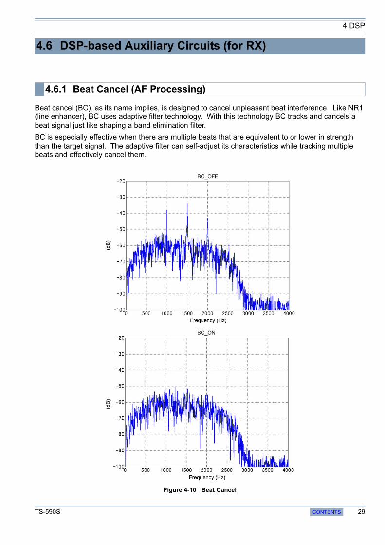
Beat cancel (BC), as its name implies, is designed to cancel unpleasant beat interference. Like NR1 (line enhancer), BC uses adaptive filter technology. With this technology BC tracks and cancels a beat signal just like shaping a band elimination filter.
BC is especially effective when there are multiple beats that are equivalent to or lower in strength than the target signal. The adaptive filter can self-adjust its characteristics while tracking multiple beats and effectively cancel them.
Figure 4-10 Beat Cancel
4.6 DSP-based Auxiliary Circuits (for RX)
4.6.1 Beat Cancel (AF Processing)
TS-590S CONTENTS 29
4 DSP
Figure 4-10 shows how BC cancels beat signals, as monitored by an FFT analyzer. Notice how multiple beats are clearly removed by BC.
There are two methods available for beat cancellation: BC1 and BC2. BC1 is tuned to be effective against weak or continuous beat interference, while BC2 cancels intermittent beats such as a CW signal. Note that since BC is designed to remove beats, it does not function in CW mode.
BC is a signal process method at the AF stage. Therefore, if there is a beat signal in proximity that is stronger than the target signal, BC effectively removes the beat interference from the audio output, but in the event the AGC is activated by the beat signal, the target signal is suppressed when received.
In such an occasion, the auto notch or manual notch filter that works at the IF stage is more effective.
We explained in the section of RX circuity that TS-590S is equipped with two noise blankers, NB1 and NB2, and that NB2 is a digital noise blanker based on the DSP. In the following section, we will explain NB2 in detail.
A noise blanker is designed to remove pulse noise at the IF stage to reveal the target signal suppressed by the AGC that was activated by the pulse noise. In addition to the analog noise blanker (NB1), the TS-590S is equipped with a newly developed digital noise blanker (NB2) so that the user can choose the blanker that is more effective for the type of noise encountered and the RX conditions.
NB2 employs a newly developed envelope tracking method, making it effective against noise that defies the tracking of the analog noise blanker (NB1).
Unlike the analog noise blanker, the procedure of NB2 is not a simple blanking of pulse noises from the target signal. NB2 removes pulse noises by tracking the RX signal level to automatically detect pulses and comparing the level of the pulses and of the target signal excluding the pulses to attenuate the pulse parts appropriately. Hence, even a long pulse can be processed without seriously degrading the target signal.
Figure 4-11 shows the time waveform of a signal containing pulse noises and a CW signal while NB2 is inactive, and Figure 4-12 shows the time waveform of the same signal while NB2 is active.
4.6.2 Noise Blanker NB2 (IF Processing)
30 CONTENTS TS-590S

4 DSP
Figure 4-11 NB2: Inactive
Figure 4-12 NB2: Active
However, depending on the nature of the pulse noise, the noise blanker cannot suppress the noise effectively. In such a case, by using other methods such as noise reduction in conjunction, the reception conditions may be improved.
There are two methods available for noise reduction on TS-590S: NR1 and NR2. You can select the noise reduction that is more effective depending on the operation mode and reception conditions.
NR1 has different algorithms that operate according to the operation mode: in voice modes (SSB, FM and AM), a newly developed noise reduction method featuring audio signals based on spectral subtraction is used. In non-voice modes (CW and FSK), noise reduction is based on a line enhancer using an adaptive filter that emphasizes the periodic signal. The noise reduction is automatically switched over when an operation mode is selected.
On the other hand, NR2 employs what is known as SPAC (speech processing by auto correlation) to piece together only the periodic components detected from the RX signal and to produce the result as audio output. Table 4-1 provides the relationship between the RX modes and NR algorithms used.
Table 4-1 Reception Modes and NR Algorithms Used
4.6.3 Overview of Noise Reduction
Noise ReductionReceive Mode
SSB/ SSB DATA FM/ AM CW/ FSK
NR1 Spectral subtraction Spectral subtraction Line enhancer
NR2 SPAC SPAC SPAC
TS-590S CONTENTS 31
4 DSP
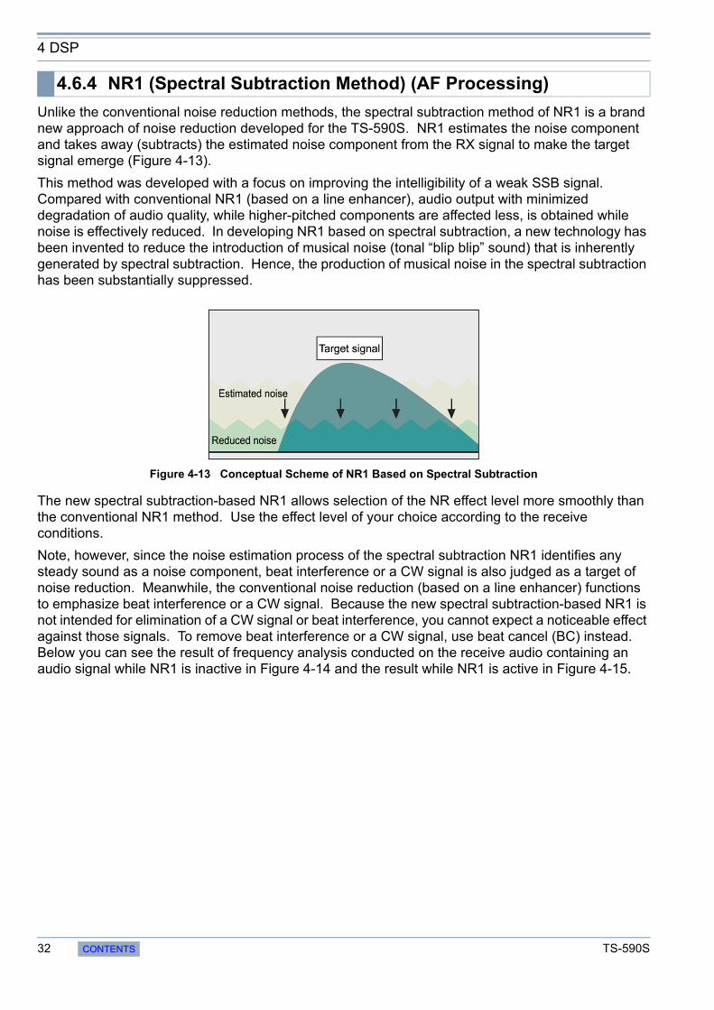
Unlike the conventional noise reduction methods, the spectral subtraction method of NR1 is a brand new approach of noise reduction developed for the TS-590S. NR1 estimates the noise component and takes away (subtracts) the estimated noise component from the RX signal to make the target signal emerge (Figure 4-13).
This method was developed with a focus on improving the intelligibility of a weak SSB signal. Compared with conventional NR1 (based on a line enhancer), audio output with minimized degradation of audio quality, while higher-pitched components are affected less, is obtained while noise is effectively reduced. In developing NR1 based on spectral subtraction, a new technology has been invented to reduce the introduction of musical noise (tonal “blip blip” sound) that is inherently generated by spectral subtraction. Hence, the production of musical noise in the spectral subtraction has been substantially suppressed.
Figure 4-13 Conceptual Scheme of NR1 Based on Spectral Subtraction
The new spectral subtraction-based NR1 allows selection of the NR effect level more smoothly than the conventional NR1 method. Use the effect level of your choice according to the receive conditions.
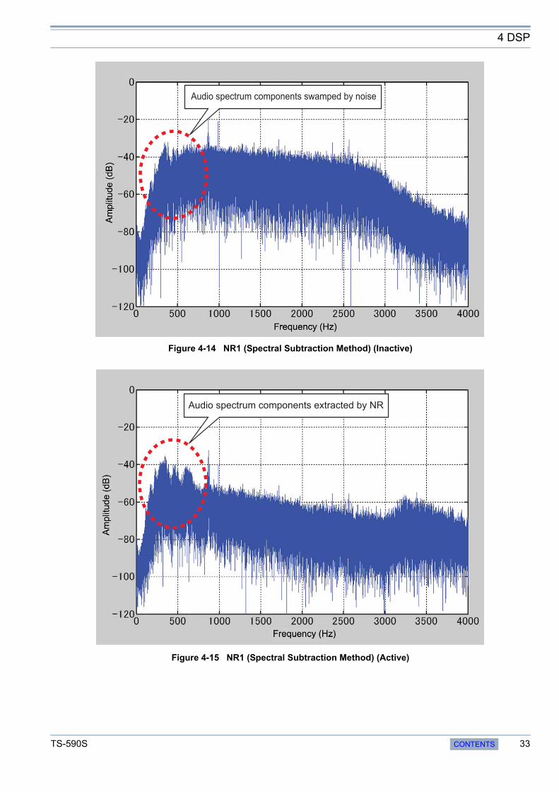
Note, however, since the noise estimation process of the spectral subtraction NR1 identifies any steady sound as a noise component, beat interference or a CW signal is also judged as a target of noise reduction. Meanwhile, the conventional noise reduction (based on a line enhancer) functions to emphasize beat interference or a CW signal. Because the new spectral subtraction-based NR1 is not intended for elimination of a CW signal or beat interference, you cannot expect a noticeable effect against those signals. To remove beat interference or a CW signal, use beat cancel (BC) instead. Below you can see the result of frequency analysis conducted on the receive audio containing an audio signal while NR1 is inactive in Figure 4-14 and the result while NR1 is active in Figure 4-15.
4.6.4 NR1 (Spectral Subtraction Method) (AF Processing)
32 CONTENTS TS-590S
4 DSP
Figure 4-14 NR1 (Spectral Subtraction Method) (Inactive)
Figure 4-15 NR1 (Spectral Subtraction Method) (Active)
Audio spectrum components swamped by noise
Audio spectrum components extracted by NR
TS-590S CONTENTS 33
4 DSP
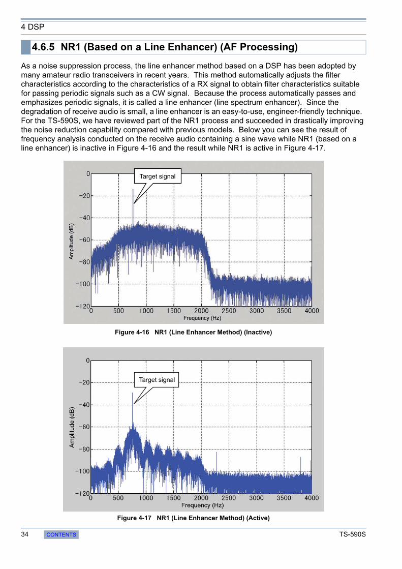
As a noise suppression process, the line enhancer method based on a DSP has been adopted by many amateur radio transceivers in recent years. This method automatically adjusts the filter characteristics according to the characteristics of a RX signal to obtain filter characteristics suitable for passing periodic signals such as a CW signal. Because the process automatically passes and emphasizes periodic signals, it is called a line enhancer (line spectrum enhancer). Since the degradation of receive audio is small, a line enhancer is an easy-to-use, engineer-friendly technique. For the TS-590S, we have reviewed part of the NR1 process and succeeded in drastically improving the noise reduction capability compared with previous models. Below you can see the result of frequency analysis conducted on the receive audio containing a sine wave while NR1 (based on a line enhancer) is inactive in Figure 4-16 and the result while NR1 is active in Figure 4-17.
Figure 4-16 NR1 (Line Enhancer Method) (Inactive)
Figure 4-17 NR1 (Line Enhancer Method) (Active)
4.6.5 NR1 (Based on a Line Enhancer) (AF Processing)
Target signal
Target signal
34 CONTENTS TS-590S

4 DSP
NR2 is what is known as SPAC. It detects periodic signals contained in the RX signal and pieces together the detected periodic signals to produce output receive audio. As a result, only the periodic signals in the receive audio emerge clearly.
NR1 based on an NR1 line enhancer is a filter in essence, but NR2 processes a RX signal in a different approach. Hence, NR2 is very effective against a signal consisting of a single frequency such as a CW signal. Also, since the processing method tends to detect the rising of a signal quickly, it also delivers an effect to make the attack part of a CW signal more distinguishable.
Hence, NR2 is a very beneficial function for CW operations. However, due to its operating principle, in the case of less periodic signals such as voice, it may generate some noise where periodic signals are joined and, thereafter, the audio quality may become less clear. In actual operation, we recommend you use NR1 in SSB mode and choose between NR1 and NR2 depending on circumstances in CW mode.
For NR2, a user can set the autocorrelation time between 2 and 20 ms that aids greatly in detecting periodic signals. The optimum autocorrelation time setting differs depending on the receive conditions, including the frequency of the target signal contained in the RX signal and noise conditions. Try to find the best autocorrelation time setting while actually receiving a signal.
Below, you can see the result of frequency analysis conducted on the receive audio containing a sine wave while NR2 is inactive in Figure 4-18 and the result while NR2 is active in Figure 4-19.
Figure 4-18 NR2: Inactive
4.6.6 NR2 (AF Processing)
Target signal
TS-590S CONTENTS 35
4 DSP
Figure 4-19 NR2: Active
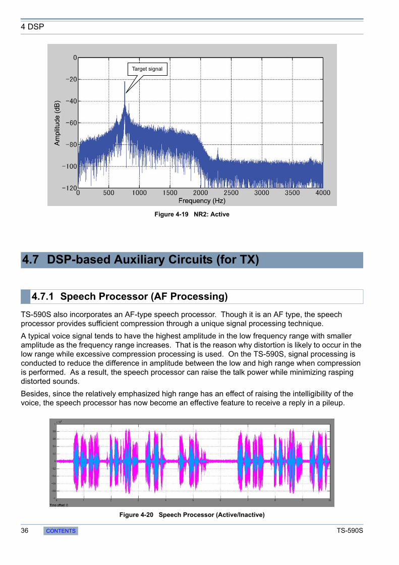
TS-590S also incorporates an AF-type speech processor. Though it is an AF type, the speech processor provides sufficient compression through a unique signal processing technique.
A typical voice signal tends to have the highest amplitude in the low frequency range with smaller amplitude as the frequency range increases. That is the reason why distortion is likely to occur in the low range while excessive compression processing is used. On the TS-590S, signal processing is conducted to reduce the difference in amplitude between the low and high range when compression is performed. As a result, the speech processor can raise the talk power while minimizing rasping distorted sounds.
Besides, since the relatively emphasized high range has an effect of raising the intelligibility of the voice, the speech processor has now become an effective feature to receive a reply in a pileup.
Figure 4-20 Speech Processor (Active/Inactive)
4.7 DSP-based Auxiliary Circuits (for TX)
4.7.1 Speech Processor (AF Processing)
Target signal
36 CONTENTS TS-590S
4 DSP
Figure 4-20 shows how the waveform changes when the speech processor is toggled between active and inactive.
You can see that when the speech processor is activated, the differences in amplitude are averaged and the talk power is increased.
The speech processor has two settings: HARD and SOFT.
HARD is a setting that you choose so as to increase talk power while tolerating some distortion and SOFT is a setting to minimize rasping distorted audio. Select either of the two settings according to your predilection and operational circumstances.
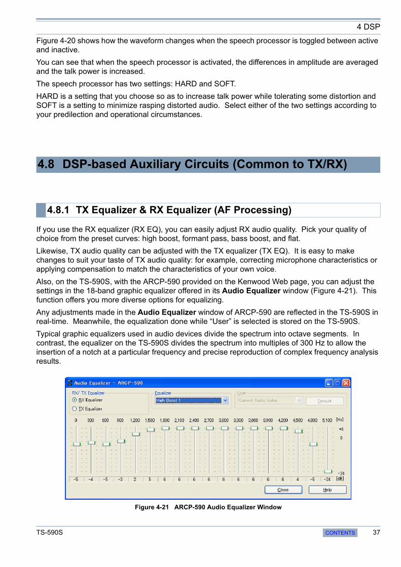
If you use the RX equalizer (RX EQ), you can easily adjust RX audio quality. Pick your quality of choice from the preset curves: high boost, formant pass, bass boost, and flat.
Likewise, TX audio quality can be adjusted with the TX equalizer (TX EQ). It is easy to make changes to suit your taste of TX audio quality: for example, correcting microphone characteristics or applying compensation to match the characteristics of your own voice.
Also, on the TS-590S, with the ARCP-590 provided on the Kenwood Web page, you can adjust the settings in the 18-band graphic equalizer offered in its Audio Equalizer window (Figure 4-21). This function offers you more diverse options for equalizing.
Any adjustments made in the Audio Equalizer window of ARCP-590 are reflected in the TS-590S in real-time. Meanwhile, the equalization done while “User” is selected is stored on the TS-590S.
Typical graphic equalizers used in audio devices divide the spectrum into octave segments. In contrast, the equalizer on the TS-590S divides the spectrum into multiples of 300 Hz to allow the insertion of a notch at a particular frequency and precise reproduction of complex frequency analysis results.
Figure 4-21 ARCP-590 Audio Equalizer Window
4.8 DSP-based Auxiliary Circuits (Common to TX/RX)
4.8.1 TX Equalizer & RX Equalizer (AF Processing)
TS-590S CONTENTS 37
5 SOFTWARE: ENHANCING OPERATING PLEASURE
In addition to the features we have explained thus far, the TS-590S comes with extensive functions to make your operation more pleasant. We will guide you through some of them.We have modified data-mode related settings to meet many different needs.
Figure 5-1 Front Panel of the TS-590S
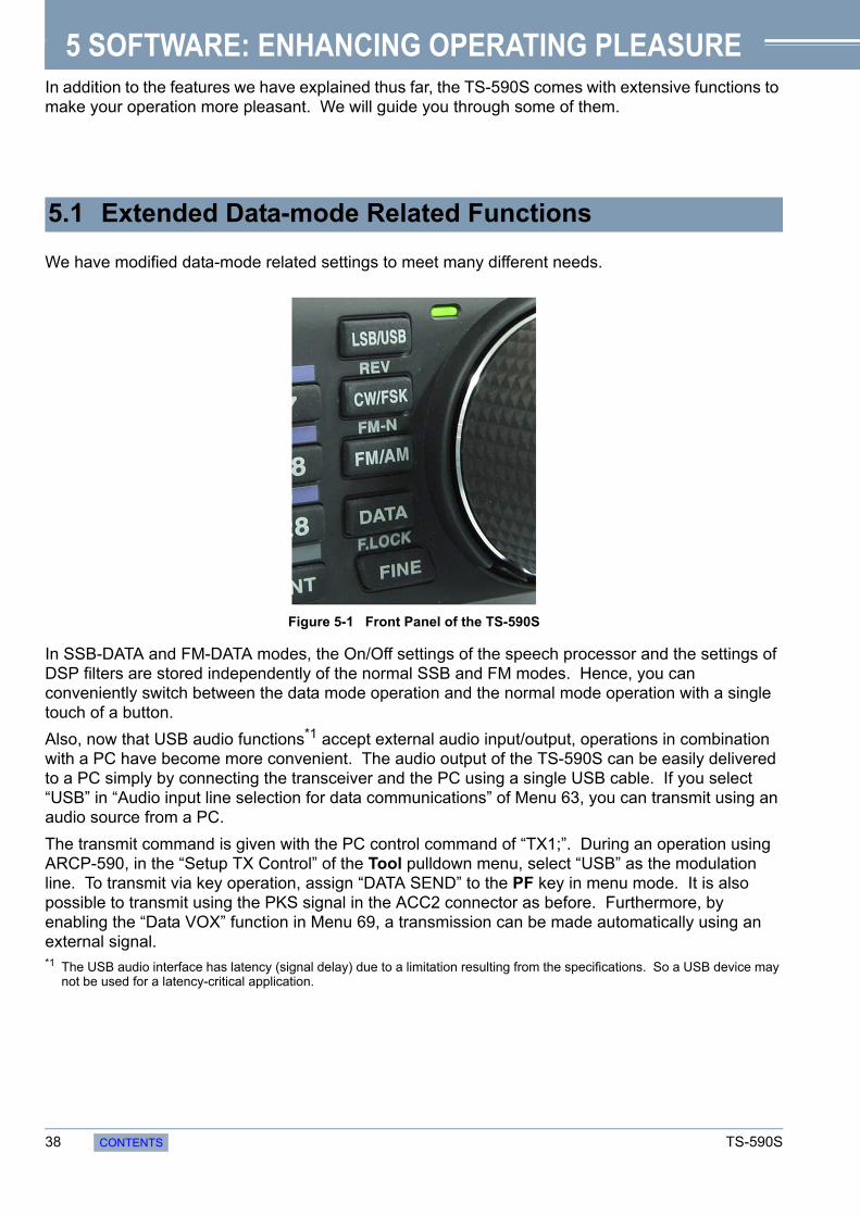
In SSB-DATA and FM-DATA modes, the On/Off settings of the speech processor and the settings of DSP filters are stored independently of the normal SSB and FM modes. Hence, you can conveniently switch between the data mode operation and the normal mode operation with a single touch of a button.
Also, now that USB audio functions*1 accept external audio input/output, operations in combination with a PC have become more convenient. The audio output of the TS-590S can be easily delivered to a PC simply by connecting the transceiver and the PC using a single USB cable. If you select “USB” in “Audio input line selection for data communications” of Menu 63, you can transmit using an audio source from a PC.
The transmit command is given with the PC control command of “TX1;”. During an operation using ARCP-590, in the “Setup TX Control” of the Tool pulldown menu, select “USB” as the modulation line. To transmit via key operation, assign “DATA SEND” to the PF key in menu mode. It is also possible to transmit using the PKS signal in the ACC2 connector as before. Furthermore, by enabling the “Data VOX” function in Menu 69, a transmission can be made automatically using an external signal.*1 The USB audio interface has latency (signal delay) due to a limitation resulting from the specifications. So a USB device may
not be used for a latency-critical application.
5.1 Extended Data-mode Related Functions
38 CONTENTS TS-590S

5 SOFTWARE: ENHANCING OPERATING PLEASURE
Also, in data modes, the specification of the receive DSP filter is automatically switched from LO CUT/HI CUT to WIDTH/SHIFT, allowing for operations with non-voice modulation types such as RTTY and PSK31.
Therefore, the IF DSP filter can be adjusted to as narrow as 50 Hz in SSB-DATA mode to deliver an interference-free output.
Setting values of WIDTH and SHIFT in SSB-DATA mode. (Hatched blocks are default values.)
Setting values of WIDTH [Hz] (14 steps)
Setting values of SHIFT [Hz] (13 steps)
If modulating the signal using an external audio input via the USB or ACC2 connector, and transmitting with the [SEND] key or the SS terminal of the ACC2 connector, the signal will not be modulated.
Conversely, if transmitting with the PKS signal of the ACC2 connector, PC control command “TX1;” or “DATA SEND” of the PF key, the signal from the microphone jack cannot be used to modulate the transceiver.
This is due to the specification that stipulates when a microphone and an external modulation source are connected at the same time, the external modulation input is muted if transmitting using the microphone, and the microphone is muted if the external modulation source is used.
Thanks to this specification, when you operate in PSK31 mode from your PC, for example, you don’t have to disconnect the microphone each time.
TS-590S is equipped with a DRV connector. The connector allows access to the drive output during the transmission. The drive output level is about 1 mW (0 dBm) and for operation in the 135 kHz band this output is used for transmission.
Also, since the active or inactive state of the DRV is stored for each band, you can interlock the status with the RX ANT connector to handily run a transverter.
Note:
Accessory/additional equipment
If you connect accessory equipment (such as an external TNC, SSTV equipment, RTTY equipment or when you connect the USB port and a PC for data communication) or additional equipment (such as a transverter or a linear amplifier) to the TS-590S, be aware that the transceiver is no longer eligible for Technical Regulations Conformity Certification and that you need to have the equipment certified to make an application. For a sample application form, visit our web site “TS-590S USB Audio Setting Manual”.
50 80 100 150 200 250 300 400 500 600 1000 1500 2000 2500
1000 1100 1200 1300 1400 1500 1600 1700 1800 1900 2000 2100 2210
Hints and Tips “Considerations on modulating the signal using an audio input from the PC”
5.2 Drive Out
TS-590S CONTENTS 39

5 SOFTWARE: ENHANCING OPERATING PLEASURE
Figure 5-2 DRV and RX ANT Connectors
Operation in the 135 kHz BandSince the Technical Regulations Conformity Certification of the transceiver is invalid for operation in the 135 kHz band, you need to make a separate application for certification to work this band.
• Higher-level knowledge and skills are required to connect external equipment to the transceiver.
• If you use external equipment, be fully aware of the connector specifications, possible loop interference, and other relevant issues.
For use of the legendary slope tuning and WIDTH/SHIFT functions incorporated in successive Kenwood HF transceivers, TS-590S stores the status of two filters (FILTER A and FILTER B) set for each type of signal. Hence, you can easily switch between the filters with a single touch of a button.
Figure 5-3 [IF FIL] Key
As an example, store the setting of a wide IF filter and narrow IF filter in FILTER A and FILTER B respectively. When you look for a station for a contact, use the wider FILTER A and once you have started a QSO, switch to the narrower FILTER B, with a touch of a button, to be able to receive the target signal only .
This filter switchover with a single action is based on the way the NAR function was used in the days when analog IF filters were used. Continuously, variable bandwidth is convenient in the sense that you can adjust it freely to whatever value you choose, but you may have difficulty operating in a timely manner in a contest or similar because it does not allow a jump to a certain value instantaneously, Therefore, we considered introducing a mechanism equivalent to the previous NAR function, but we were swayed by the opinion that a user wants to operate with normal bandwidth usually, yet still maintain the to switch to a wider bandwidth when it is required. Consequently, to satisfy both needs, we have devised a system to store settings freely.
5.3 Single Button Toggles IF Filters between A and B
Hints and Tips “Is this filter switchover with a single touch of a button different from NAR?”
40 CONTENTS TS-590S
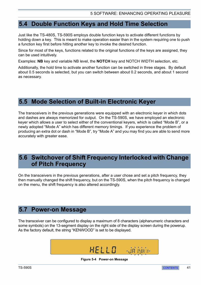
5 SOFTWARE: ENHANCING OPERATING PLEASURE
Just like the TS-480S, TS-590S employs double function keys to activate different functions by holding down a key. This is meant to make operation easier than in the system requiring one to push a function key first before hitting another key to invoke the desired function.
Since for most of the keys, functions related to the original functions of the keys are assigned, they can be used intuitively.
Examples: NB key and variable NB level, the NOTCH key and NOTCH WIDTH selection, etc.
Additionally, the hold time to activate another function can be switched in three stages. By default about 0.5 seconds is selected, but you can switch between about 0.2 seconds, and about 1 second as necessary.
The transceivers in the previous generations were equipped with an electronic keyer in which dots and dashes are always memorized for output. On the TS-590S, we have employed an electronic keyer which allows a user to select either of the conventional keyers, which is called “Mode B”, or a newly adopted “Mode A” which has different memory timings. If you experience the problem of producing an extra dot or dash in “Mode B”, try “Mode A” and you may find you are able to send more accurately with greater ease.
On the transceivers in the previous generations, after a user chose and set a pitch frequency, they then manually changed the shift frequency, but on the TS-590S, when the pitch frequency is changed on the menu, the shift frequency is also altered accordingly.
The transceiver can be configured to display a maximum of 8 characters (alphanumeric characters and some symbols) on the 13-segment display on the right side of the display screen during the powerup. As the factory default, the string “KENWOOD” is set to be displayed.
Figure 5-4 Power-on Message
5.4 Double Function Keys and Hold Time Selection
5.5 Mode Selection of Built-in Electronic Keyer
5.6 Switchover of Shift Frequency Interlocked with Change of Pitch Frequency
5.7 Power-on Message
TS-590S CONTENTS 41
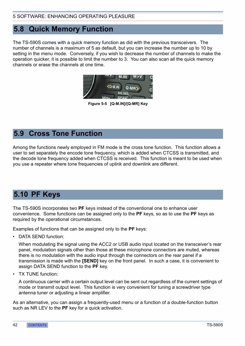
5 SOFTWARE: ENHANCING OPERATING PLEASURE
The TS-590S comes with a quick memory function as did with the previous transceivers. The number of channels is a maximum of 5 as default, but you can increase the number up to 10 by setting in the menu mode. Conversely, if you wish to decrease the number of channels to make the operation quicker, it is possible to limit the number to 3. You can also scan all the quick memory channels or erase the channels at one time.
Figure 5-5 [Q-M.IN]/[Q-MR] Key
Among the functions newly employed in FM mode is the cross tone function. This function allows a user to set separately the encode tone frequency, which is added when CTCSS is transmitted, and the decode tone frequency added when CTCSS is received. This function is meant to be used when you use a repeater where tone frequencies of uplink and downlink are different.
The TS-590S incorporates two PF keys instead of the conventional one to enhance user convenience. Some functions can be assigned only to the PF keys, so as to use the PF keys as required by the operational circumstances.
Examples of functions that can be assigned only to the PF keys:
• DATA SEND function:
When modulating the signal using the ACC2 or USB audio input located on the transceiver’s rear panel, modulation signals other than those at these microphone connectors are muted, whereas there is no modulation with the audio input through the connectors on the rear panel if a transmission is made with the [SEND] key on the front panel. In such a case, it is convenient to assign DATA SEND function to the PF key.
• TX TUNE function:
A continuous carrier with a certain output level can be sent out regardless of the current settings of mode or transmit output level. This function is very convenient for tuning a screwdriver type antenna tuner or adjusting a linear amplifier.
As an alternative, you can assign a frequently-used menu or a function of a double-function button such as NR LEV to the PF key for a quick activation.
5.8 Quick Memory Function
5.9 Cross Tone Function
5.10 PF Keys
42 CONTENTS TS-590S
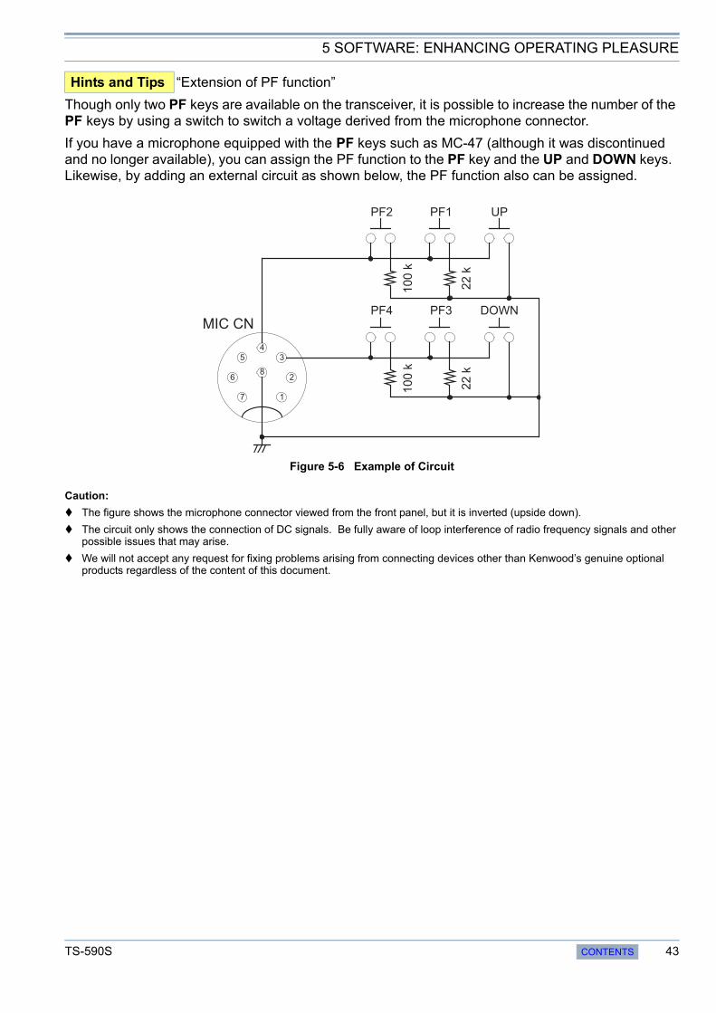
5 SOFTWARE: ENHANCING OPERATING PLEASURE
Though only two PF keys are available on the transceiver, it is possible to increase the number of the PF keys by using a switch to switch a voltage derived from the microphone connector.
If you have a microphone equipped with the PF keys such as MC-47 (although it was discontinued and no longer available), you can assign the PF function to the PF key and the UP and DOWN keys. Likewise, by adding an external circuit as shown below, the PF function also can be assigned.
Figure 5-6 Example of Circuit
Caution:
The figure shows the microphone connector viewed from the front panel, but it is inverted (upside down).
The circuit only shows the connection of DC signals. Be fully aware of loop interference of radio frequency signals and other possible issues that may arise.
We will not accept any request for fixing problems arising from connecting devices other than Kenwood’s genuine optional products regardless of the content of this document.
Hints and Tips “Extension of PF function”
1
2
3
4
5
6
7
8
PF2 PF1 UP
PF4 PF3 DOWN
MIC CN
10
0 k
22
k
10
0 k
22
k
TS-590S CONTENTS 43

5 SOFTWARE: ENHANCING OPERATING PLEASURE
The optional VGS-1 voice guide and storage unit can be installed on the transceiver. The voice guide and audio recording function that are acclaimed by sight-impaired operators become available. The following are the details of the VGS-1 and new functions added for the current version.
Figure 5-7 VGS-1
Voice Guide Function
On the TS-590S, in addition to the conventional audio announcements, the readings of the multimeter (SWR meter, ALC meter and COMP meter) can be also announced.
Also, by setting the auto announcement to be disabled in the menu mode, the announcements can be made only when the VOICE key (that is to be assigned to the PF key) is pressed.
Voice Storage Function
A maximum of 4 channels can be used for storing voice for transmission. This is a very convenient option for an operator who participates in a contest in SSB mode. (The CW message memory function is available on the transceiver and does not require VGS-1.)
Channel 4 of the voice recording channels for transmission can be assigned for recording a received voice signal. Anytime upon a press of the [REC] key, you can store the voice signal received over the past 30 seconds in flash memory and replay the voice as required.
5.11 Expansion of Voice Guide Function (Optional VGS-1 Required)
44 CONTENTS TS-590S
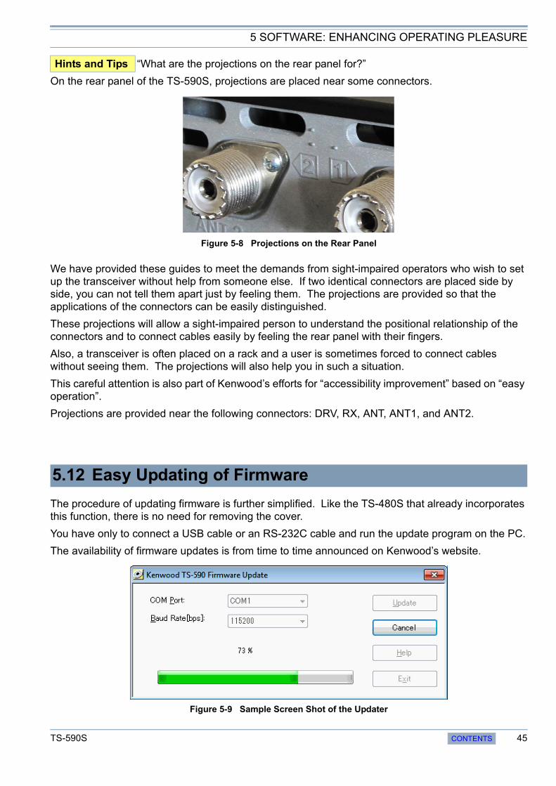
5 SOFTWARE: ENHANCING OPERATING PLEASURE
On the rear panel of the TS-590S, projections are placed near some connectors.
Figure 5-8 Projections on the Rear Panel
We have provided these guides to meet the demands from sight-impaired operators who wish to set up the transceiver without help from someone else. If two identical connectors are placed side by side, you can not tell them apart just by feeling them. The projections are provided so that the applications of the connectors can be easily distinguished.
These projections will allow a sight-impaired person to understand the positional relationship of the connectors and to connect cables easily by feeling the rear panel with their fingers.
Also, a transceiver is often placed on a rack and a user is sometimes forced to connect cables without seeing them. The projections will also help you in such a situation.
This careful attention is also part of Kenwood’s efforts for “accessibility improvement” based on “easy operation”.
Projections are provided near the following connectors: DRV, RX, ANT, ANT1, and ANT2.
The procedure of updating firmware is further simplified. Like the TS-480S that already incorporates this function, there is no need for removing the cover.
You have only to connect a USB cable or an RS-232C cable and run the update program on the PC.
The availability of firmware updates is from time to time announced on Kenwood’s website.
Figure 5-9 Sample Screen Shot of the Updater
Hints and Tips “What are the projections on the rear panel for?”
5.12 Easy Updating of Firmware
TS-590S CONTENTS 45

6 APPEARANCE DESIGN: “DESIGN CONCEPT” REVEALED BY DESIGNING ENGINEER
The design development of the TS-590S was started by asking myself “What are the characteristics that make Kenwood’s HF transceivers just what they are?” Among the key words adopted to describe the characteristics were “innovativeness”, “high quality” and “sharpness”, based on which I pursued a design that captures the trends of the times.
On the development of TS-590S, I exchanged lively discussions with my colleagues and finally settled on the design concept of “deep and heavy”. This means “a genuine HF transceiver that nobody can make light of” or “a design that, when it is placed among other peripheral devices in a shack (which is inevitable due to the nature of the product), does not stand out distastefully”.
The work of designing a transceiver does not end with just creating an outer shape, but includes a wide variety of tasks ranging from scrutinizing colors, materials, character fonts, etc., to examining the size, thickness and balance of characters displayed in the LCD.
A horizontal line penetrating the front panel describes the sharpness and the DNA of Kenwood’s HF transceivers that has been handed down from generation to generation.
When it comes to the main knob that a user touches most often, I have devised a design that never makes a user tired from long hours of operation or slips out of the hand while handling. Also, for the material I have employed fluorine-containing rubber that does not attract dirt and dust.
As for the color of the body, I have selected matte-black finish to give it a typical look of a transceiver and to prevent the reflection of light as much as possible when a user operates from a portable station.
Much attention is also paid to the printing of the characters and graphics to express the typical preciseness of Kenwood’s HF transceivers and to deliver better visibility to enable intuitive operations and eye-friendly views.
Figure 6-1 A Sketch of the TS-590S
Figure 6-1 shows a sketch that is almost complete. We make a lot of such sketches in the process of finalizing the outer design for the purpose of discussions before creating a full-size mock-up sample.
The TS-590S is an HF transceiver launched by Kenwood after a long interval. We felt desperately sorry each time a customer asked us, at the annual ham fairs, when Kenwood’s new HF transceiver would be available.
I was more than happy that our hard work was rewarded when the TS-590S was eventually launched and a customer told me “My patience finally paid off!” It was my greatest joy as a designer.
Finally, as one of the developers, I hope the TS-590S will be used by as many amateur radio operators as possible.
46 CONTENTS TS-590S

7 STRUCTURAL FEATURES
We have designed the chassis of the TS-590S to endure heavy-duty operation.
The PCBs are placed as follows: FINAL UNIT on the upper side of the chassis, TX-RX UNIT and LO UNIT on the lower side, CONTROL UNIT beneath the LO UNIT, NB UNIT and DISPLAY UNIT in front.
We have placed two cooling fans in the front of the chassis.
The cooling fans have two operation modes: LO and HI. By rotating two fan motors at a lower revolution speed, we aimed to reduce the operating noise.
Figure 7-1 Layout of Printed Circuits Boards of the TS-590S Series
We have optimized the chassis structure using computer-aided thermal analysis to improve the heat dissipation performance. We have designed the chassis to facilitate smooth air flow.
Figure 7-2 Results of Computer-aided Thermal Analysis
7.1 Cooling
FINAL UNIT
TWIN FAN
TX-RX UNIT
LO
UN
IT
NB UNIT
CO
NT
RO
L U
NIT
DISPLAY UNIT
TS-590S CONTENTS 47
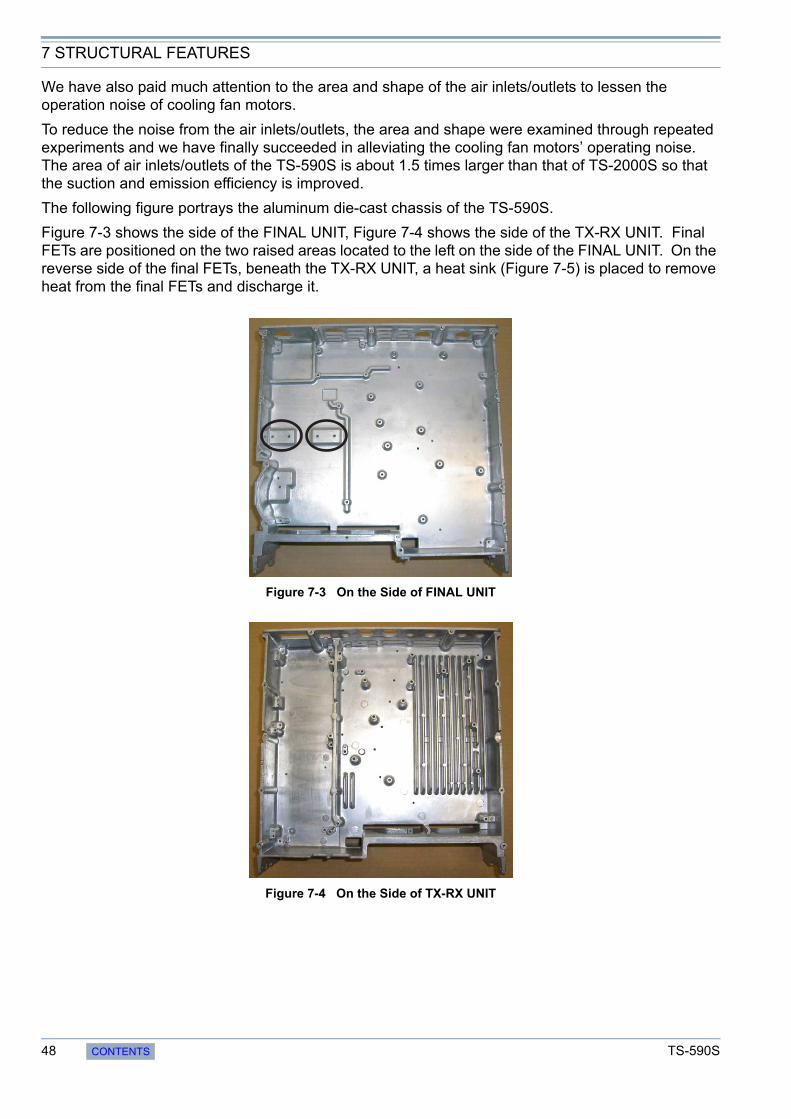
7 STRUCTURAL FEATURES
We have also paid much attention to the area and shape of the air inlets/outlets to lessen the operation noise of cooling fan motors.
To reduce the noise from the air inlets/outlets, the area and shape were examined through repeated experiments and we have finally succeeded in alleviating the cooling fan motors’ operating noise. The area of air inlets/outlets of the TS-590S is about 1.5 times larger than that of TS-2000S so that the suction and emission efficiency is improved.
The following figure portrays the aluminum die-cast chassis of the TS-590S.
Figure 7-3 shows the side of the FINAL UNIT, Figure 7-4 shows the side of the TX-RX UNIT. Final FETs are positioned on the two raised areas located to the left on the side of the FINAL UNIT. On the reverse side of the final FETs, beneath the TX-RX UNIT, a heat sink (Figure 7-5) is placed to remove heat from the final FETs and discharge it.
Figure 7-3 On the Side of FINAL UNIT
Figure 7-4 On the Side of TX-RX UNIT
48 CONTENTS TS-590S

7 STRUCTURAL FEATURES
Figure 7-5 Heat Sink Section
We will provide the temperature data when a continuous transmission is made at a 25°C or 77°F room temperature so that you can understand the TS-590S’s superb cooling capability.
Figure 7-6 Temperature Data while Transmitting Continuously
As can be seen from the above graph, the output power does not drop (the protection is not activated) while transmitting continuously for more than two hours at a 25°C or 77°F room temperature with an output power of 100 W.
As explained above, TS-590S is designed for heavy-duty operation as were the previous HF transceivers, but, as a general rule not limited to Kenwood products, the higher the temperature, the shorter the life span of an electronic device. Therefore, we recommend you use the transceiver with an appropriate output power that suits the circumstances in order to prolong the longevity of the transceiver.
TS-590S CONTENTS 49

7 STRUCTURAL FEATURES
“We wanted to complete the display without uneven brightness!” That was our goal of designing the display screen, or the “face” of the transceiver. On the TS-590S, after repeated examinations and trials, we have finally reached our goal of a display with perfectly even brightness.
The secret of this even brightness lies in the illumination structure of the LCD.
The TS-590S’s illumination structure is a bottom direct-lit type backlight structure in which LEDs are lit from the reverse side of the LCD. In the stage of discussing the structure, we have also examined front-lit and edge-lit designs that have been already proven in the previous transceivers, but they didn’t suit the display size of the TS-590S, resulting in uneven illumination. So, we focused on the the bottom direct-lit type backlight structure and further studied the design.
We would like you to confirm the beauty of the display with your own eyes.
Also, as the first trial on a Kenwood HF transceiver, the color of the backlight now can be switched between amber and green. At first, the color of the backlight was amber only but, considering color visibility differs from one amateur radio operator to another in the world, we have added green. You can choose either amber or green backlighting, whichever pleases you most.
In addition to the backlight itself, we also carefully designed the brightness (dimmer setting) of the backlight and the segment displays for better visibility. You can choose among 7 steps of brightness (OFF and 1 though 6) of the backlight in the menu mode.
The TS-590S has more dimmer setting steps than the TS-570S or TS-2000S, allowing a user to adjust the backlight brightness to suit the installation environment.
For the segment displays on the LCD, we have adopted a large-size, positive LCD.
Focusing on the visibility, for 7-segment and 13-segment displays, we have adopted the same large-size characters as in the TS-570S that were highly evaluated. The type of LCD chosen is a semi-transmissive TN LCD (1/3 duty) that has high contrast.
Good outdoor sunlight visibility is another reason why we have chosen a semi-transmissive LCD. The TS-590S has a semi-transmissive LCD using a white reflection plate. And this LCD type delivers comfortable visibility under sunlight. Hence, the transceiver maintains good visibility characteristics outdoors as well as indoors.
Figure 7-7 Amber and Green
7.2 LCD
50 CONTENTS TS-590S

7 STRUCTURAL FEATURES
We have designed the main control knob located in the center of the front panel, focusing on easy handling and good appearance.
For the encoder, a 250-pulse magnetic encoder is adopted, which enables the pulses are multiplied by 4 using software to produce 1,000 pulses per revolution so that a user can tune to the desired frequency smoothly.
Each of the aluminum parts is machined with CNC (computerized numeric control) and treated with spin finish. We also paid careful attention to the color of the main control knob; we have colored the knob with a color alumite treatment.
We made samples repeatedly until the desired color was finalized. The alumite color is adjusted to match the rubber color of the knob ring and the paint color of the front panel in order to express the integration and massiveness of the entire panel.
Not only for the main control knob, easy handling was our priority when designing the sizes and locations of other controls (knobs and keys). We carefully studied the sizes and layout of the knobs so that a finger will not hit the adjacent knob when a user turns a knob.
Though the TS-590S has a relatively compact front panel as an HF transceiver, the controls are positioned for comfortable operation.
Figure 7-8 Main Control Knob
7.3 Main Control Knob
Main control knob
TS-590S CONTENTS 51
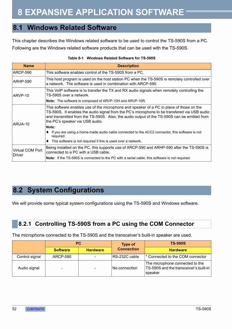
8 EXPANSIVE APPLICATION SOFTWARE
This chapter describes the Windows related software to be used to control the TS-590S from a PC.
Following are the Windows related software products that can be used with the TS-590S.
Table 8-1 Windows Related Software for TS-590S
We will provide some typical system configurations using the TS-590S and Windows software.
The microphone connected to the TS-590S and the transceiver’s built-in speaker are used.
8.1 Windows Related Software
Name Description
ARCP-590 This software enables control of the TS-590S from a PC.
ARHP-590This host program is used on the host station PC when the TS-590S is remotely controlled over a network. The software is used in combination with ARCP-590.
ARVP-10This VoIP software is to transfer the TX and RX audio signals when remotely controlling the TS-590S over a network.
Note: The software is composed of ARVP-10H and ARVP-10R.
ARUA-10
This software enables use of the microphone and speaker of a PC in place of those on the TS-590S. It enables the audio signal from the PC’s microphone to be transfered via USB audio and transmitted from the TS-590S. Also, the audio output of the TS-590S can be emitted from the PC’s speaker via USB audio.
Note:
If you are using a home-made audio cable connected to the ACC2 connector, this software is not required.
This software is not required if this is used over a network.
Virtual COM Port Driver
Being installed on the PC, this supports use of ARCP-590 and ARHP-590 after the TS-590S is connected to a PC with a USB cable.
Note: If the TS-590S is connected to the PC with a serial cable, this software is not required.
8.2 System Configurations
8.2.1 Controlling TS-590S from a PC using the COM Connector
PC Type of Connection
TS-590S
Software Hardware Hardware
Control signal ARCP-590 - RS-232C cable * Connected to the COM connector
Audio signal - - No connectionThe microphone connected to the TS-590S and the transceiver’s built-in speaker
52 CONTENTS TS-590S
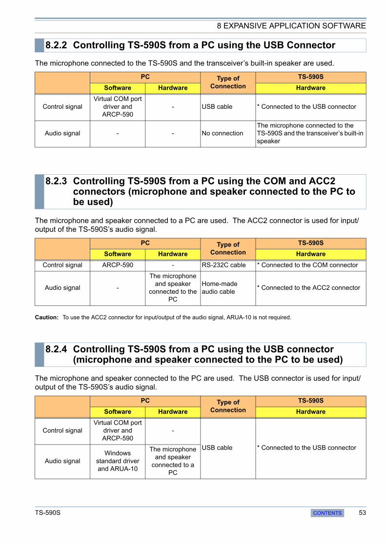
8 EXPANSIVE APPLICATION SOFTWARE
The microphone connected to the TS-590S and the transceiver’s built-in speaker are used.
The microphone and speaker connected to a PC are used. The ACC2 connector is used for input/output of the TS-590S’s audio signal.
Caution: To use the ACC2 connector for input/output of the audio signal, ARUA-10 is not required.
The microphone and speaker connected to the PC are used. The USB connector is used for input/output of the TS-590S’s audio signal.
8.2.2 Controlling TS-590S from a PC using the USB Connector
PC Type of Connection
TS-590S
Software Hardware Hardware
Control signalVirtual COM port
driver and ARCP-590
- USB cable * Connected to the USB connector
Audio signal - - No connectionThe microphone connected to the TS-590S and the transceiver’s built-in speaker
8.2.3 Controlling TS-590S from a PC using the COM and ACC2 connectors (microphone and speaker connected to the PC to be used)
PC Type of Connection
TS-590S
Software Hardware Hardware
Control signal ARCP-590 - RS-232C cable * Connected to the COM connector
Audio signal -
The microphone and speaker
connected to the PC
Home-made audio cable
* Connected to the ACC2 connector
8.2.4 Controlling TS-590S from a PC using the USB connector (microphone and speaker connected to the PC to be used)
PC Type of Connection
TS-590S
Software Hardware Hardware
Control signalVirtual COM port
driver and ARCP-590
-
USB cable * Connected to the USB connector
Audio signalWindows
standard driver and ARUA-10
The microphone and speaker
connected to a PC
TS-590S CONTENTS 53

8 EXPANSIVE APPLICATION SOFTWARE
Caution: When the USB connector is used for input/output of the audio signal on the host station, ARUA-10 is not required neither.
ARCP-590 (Amateur Radio Control Program for TS-590S) is software enabling control of the TS-590S from a PC.
Figure 8-1 Main Window of ARCP-590
ARCP-590 is available free and can be downloaded from Kenwood’s website.
URLs from which ARCP-590 can be downloaded:
http://www.kenwood.com/i/products/info/amateur/software_download.html
As with ARCP-480 for the TS-480S, the new ARCP-590 program is designed to control virtually all of the functions on the TS-590S transceiver.
8.2.5 Controlling TS-590S from a PC on a Remote Site
Remote Station (PC that remotely controls the transceiver) Type of
Connection
Host station (PC that is located near the TS-590S)
Software Hardware Software Hardware
Control signal ARCP-590 -
Network
ARHP-590* Connected to the COM or USB connector
Audio signalARVP-10R or generic VoIP
software
The microphone and speaker
connected to a PC
ARVP-10H or generic VoIP software
* Connected to the ACC2 or USB connector
8.3 New ARCP-590 (Amateur Radio Control Program for TS-590S) Freeware
54 CONTENTS TS-590S
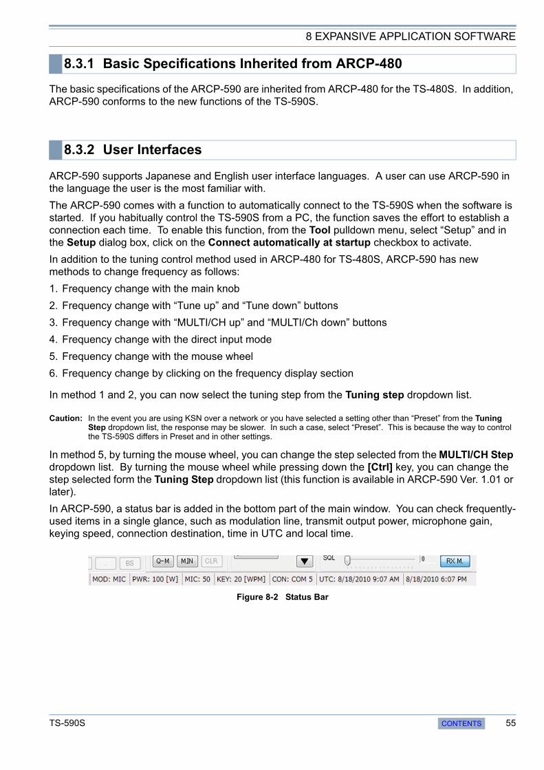
8 EXPANSIVE APPLICATION SOFTWARE
The basic specifications of the ARCP-590 are inherited from ARCP-480 for the TS-480S. In addition, ARCP-590 conforms to the new functions of the TS-590S.
ARCP-590 supports Japanese and English user interface languages. A user can use ARCP-590 in the language the user is the most familiar with.
The ARCP-590 comes with a function to automatically connect to the TS-590S when the software is started. If you habitually control the TS-590S from a PC, the function saves the effort to establish a connection each time. To enable this function, from the Tool pulldown menu, select “Setup” and in the Setup dialog box, click on the Connect automatically at startup checkbox to activate.
In addition to the tuning control method used in ARCP-480 for TS-480S, ARCP-590 has new methods to change frequency as follows:
1. Frequency change with the main knob
2. Frequency change with “Tune up” and “Tune down” buttons
3. Frequency change with “MULTI/CH up” and “MULTI/Ch down” buttons
4. Frequency change with the direct input mode
5. Frequency change with the mouse wheel
6. Frequency change by clicking on the frequency display section
In method 1 and 2, you can now select the tuning step from the Tuning step dropdown list.
Caution: In the event you are using KSN over a network or you have selected a setting other than “Preset” from the Tuning Step dropdown list, the response may be slower. In such a case, select “Preset”. This is because the way to control the TS-590S differs in Preset and in other settings.
In method 5, by turning the mouse wheel, you can change the step selected from the MULTI/CH Step dropdown list. By turning the mouse wheel while pressing down the [Ctrl] key, you can change the step selected form the Tuning Step dropdown list (this function is available in ARCP-590 Ver. 1.01 or later).
In ARCP-590, a status bar is added in the bottom part of the main window. You can check frequently-used items in a single glance, such as modulation line, transmit output power, microphone gain, keying speed, connection destination, time in UTC and local time.
Figure 8-2 Status Bar
8.3.1 Basic Specifications Inherited from ARCP-480
8.3.2 User Interfaces
TS-590S CONTENTS 55
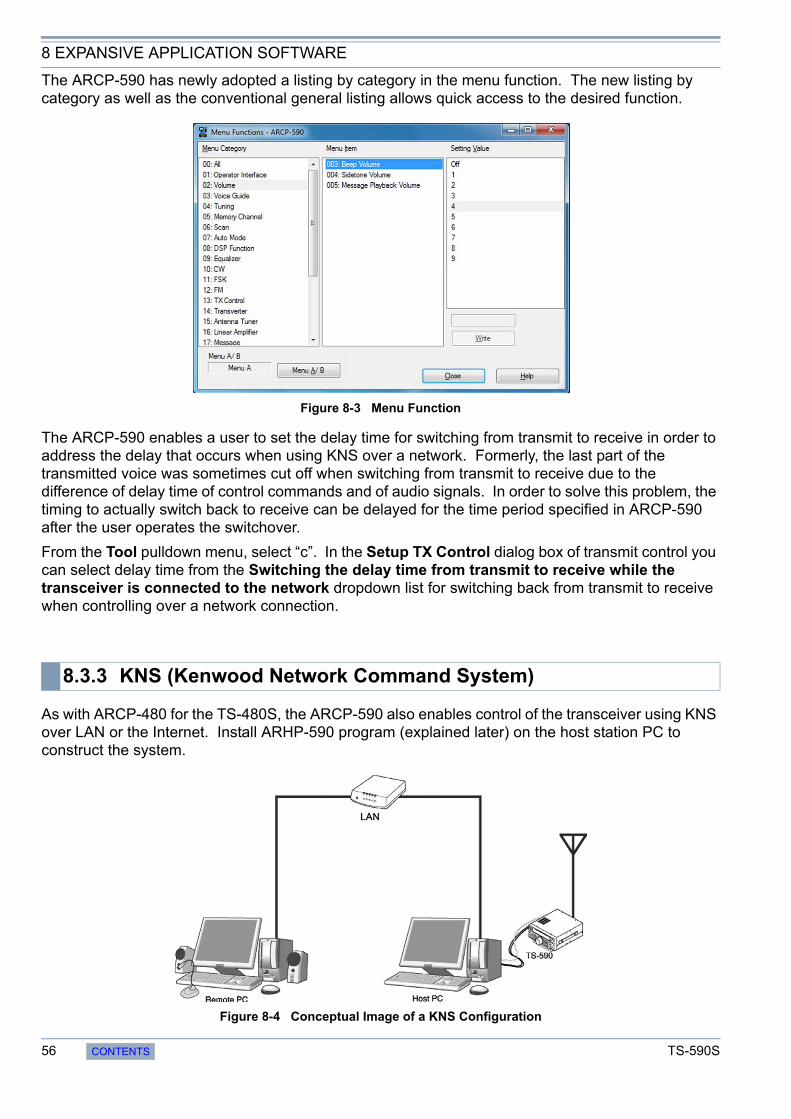
8 EXPANSIVE APPLICATION SOFTWARE
The ARCP-590 has newly adopted a listing by category in the menu function. The new listing by category as well as the conventional general listing allows quick access to the desired function.
Figure 8-3 Menu Function
The ARCP-590 enables a user to set the delay time for switching from transmit to receive in order to address the delay that occurs when using KNS over a network. Formerly, the last part of the transmitted voice was sometimes cut off when switching from transmit to receive due to the difference of delay time of control commands and of audio signals. In order to solve this problem, the timing to actually switch back to receive can be delayed for the time period specified in ARCP-590 after the user operates the switchover.
From the Tool pulldown menu, select “c”. In the Setup TX Control dialog box of transmit control you can select delay time from the Switching the delay time from transmit to receive while the transceiver is connected to the network dropdown list for switching back from transmit to receive when controlling over a network connection.
As with ARCP-480 for the TS-480S, the ARCP-590 also enables control of the transceiver using KNS over LAN or the Internet. Install ARHP-590 program (explained later) on the host station PC to construct the system.
Figure 8-4 Conceptual Image of a KNS Configuration
8.3.3 KNS (Kenwood Network Command System)
56 CONTENTS TS-590S
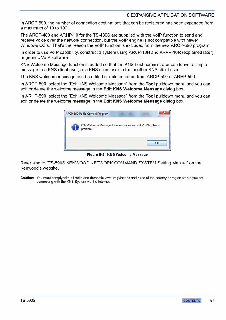
8 EXPANSIVE APPLICATION SOFTWARE
In ARCP-590, the number of connection destinations that can be registered has been expanded from a maximum of 10 to 100.
The ARCP-480 and ARHP-10 for the TS-480S are supplied with the VoIP function to send and receive voice over the network connection, but the VoIP engine is not compatible with newer Windows OS’s. That’s the reason the VoIP function is excluded from the new ARCP-590 program.
In order to use VoIP capability, construct a system using ARVP-10H and ARVP-10R (explained later) or generic VoIP software.
KNS Welcome Message function is added so that the KNS host administrator can leave a simple message to a KNS client user; or a KNS client user to the another KNS client user.
The KNS welcome message can be edited or deleted either from ARCP-590 or ARHP-590.
In ARCP-590, select the “Edit KNS Welcome Message” from the Tool pulldown menu and you can edit or delete the welcome message in the Edit KNS Welcome Message dialog box.
In ARHP-590, select the “Edit KNS Welcome Message” from the Tool pulldown menu and you can edit or delete the welcome message in the Edit KNS Welcome Message dialog box.
Figure 8-5 KNS Welcome Message
Refer also to “TS-590S KENWOOD NETWORK COMMAND SYSTEM Setting Manual” on the Kenwood’s website.
Caution: You must comply with all radio and domestic laws, regulations and rules of the country or region where you are connecting with the KNS System via the Internet.
TS-590S CONTENTS 57
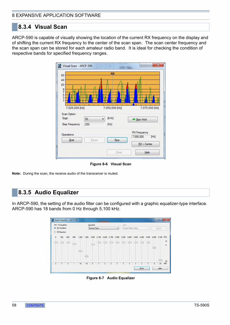
8 EXPANSIVE APPLICATION SOFTWARE
ARCP-590 is capable of visually showing the location of the current RX frequency on the display and of shifting the current RX frequency to the center of the scan span. The scan center frequency and the scan span can be stored for each amateur radio band. It is ideal for checking the condition of respective bands for specified frequency ranges.
Figure 8-6 Visual Scan
Note: During the scan, the receive audio of the transceiver is muted.
In ARCP-590, the setting of the audio filter can be configured with a graphic equalizer-type interface. ARCP-590 has 18 bands from 0 Hz through 5,100 kHz.
Figure 8-7 Audio Equalizer
8.3.4 Visual Scan
8.3.5 Audio Equalizer
58 CONTENTS TS-590S

8 EXPANSIVE APPLICATION SOFTWARE
ARHP-590 is the host application to control the TS-590S with Kenwood Network Command System (KNS).
Figure 8-8 Main Window of ARHP-590
ARHP-590 is available free and can be downloaded from Kenwood’s website.
URLs from which ARHP-590 can be downloaded:
http://www.kenwood.com/i/products/info/amateur/software_download.html
Refer also to “TS-590S KENWOOD NETWORK COMMAND SYSTEM Setting Manual” on the Kenwood’s website.
The basic specifications of the ARHP-590 are inherited from ARHP-10 for the TS-480E. In addition, ARCP-590 is compatible with the new functions of the TS-590S.
ARHP-590 supports Japanese and English user interface languages. A user can use ARHP-590 in the language the user is the most familiar with.
In ARHP-590, a function to automatically run the program when Windows starts is added. Using this function, upon restart of the PC, ARHP-590 can be activated and a connection is made automatically. To enable this function, select “Setup” from the Tool pulldown menu and in the Setup dialog box, click on the Activating automatically when Windows starts checkbox.
8.4 ARHP-590 (Amateur Radio Host Program) Freeware
8.4.1 Basic Specifications Inherited from ARHP-10
8.4.2 User Interfaces
TS-590S CONTENTS 59

8 EXPANSIVE APPLICATION SOFTWARE
ARHP-590 allows a user to check the operating status of ARHP-590 and TS-590S even after minimized. You can check the status of the power of the TS-590S (Power ON or Power OFF) and your connection and transmission statuses.
Figure 8-9 Checking the Operating Status
For details of Kenwood Network Command System, refer to 8.3.3. KNS (Kenwood Network Command System).
ARHP-590 has a capability to disable the AF gain control from the ARCP-590. While AF gain is controlled from ARCP-590, the audio volume of the TS-590S may be adjusted in an unexpected way. Therefore, we have added a function to disable this control.
To enable this function, from the Tool pulldown menu, select “Setup” and click on the Prohibits control of AF gain from ARCP-590 checkbox.
We have released ARUA-10, the USB audio control software to allow the PC’s microphone and speaker to be used in place those of the TS-590S.
ARUA-10 is available free and can be downloaded from Kenwood’s website.
URLs from which ARUA-10 can be downloaded:
http://www.kenwood.com/i/products/info/amateur/software_download.html
Refer also to “TS-590S USB Audio Setting Manual” on the Kenwood’s website.
Caution:
For USB audio, time delay is unavoidable due to its operating principle. Therefore, USB audio cannot be used for a latency-critical application (e.g. operations in a contest or pileup where a quick response is essential).
During the operation with KNS over a network connection, ARUA-10 is not required.
8.4.3 KNS (Kenwood Network Command System)
8.4.4 Disabling AF Gain Control from ARCP-590
8.5 New ARUA-10 (USB Audio Controller) Freeware
60 CONTENTS TS-590S

8 EXPANSIVE APPLICATION SOFTWARE
If ARUA-10 and ARCP-590 are used in combination, you have only to connect the TS-590S and a PC with a single USB cable to use the microphone and speaker connected to the PC in place of those on the transceiver. To use ARCP-590 over a USB cable connection, the virtual COM port driver needs to be installed.
If you use only ARUA-10 over a USB cable connection, the virtual port driver doesn’t need to be installed. If you use the built-in USB sound function of the TS-590S only, the function runs on the Window’s standard driver.
ARUA-10 bridges the TS-590S’s built-in USB sound function (USB audio device) and the sound device that controls the microphone and speaker on the PC.
A voice signal from the microphone connected to the PC is input into the modulation input of the TS-590S’s USB audio device. The audio output of the TS-590S’s USB audio device is emitted from the PC’s speaker.
Figure 8-10 Flow of the Audio Signal
Configure the necessary settings to use ARUA-10.
Right click the “ARUA-10” icon in the Windows task tray and select “Device Setup” in the menu and the Setup dialog box will appear. In the Device tab, you can set up the device to input/output the audio signal.
8.5.1 Basic Functions
8.5.2 Operation
8.5.3 Setup
TS-590S CONTENTS 61

8 EXPANSIVE APPLICATION SOFTWARE
Figure 8-11 Device Tab
In the “Reception Output” of the Transceiver frame, “Microphone (USB Audio CODEC)” must be selected.
In the “Modulation Input” of the Transceiver frame, “Speaker (USB Audio CODEC)” must be selected.
In the “Microphone” of the PC frame, specify the microphone of the sound device.
In the “Speakers” of the PC frame, specify the speaker of the sound device.
You can check the name of the sound device in the entry under “Sound video and game controllers” category in Windows Device Manager.
To start ARUA-10, after above settings completes, right click the “ARUA-10” icon in the Windows task tray and select “Start” in the menu.
To stop ARUA-10, right click the “ARUA-10” icon in the Windows task tray and select “Stop” in the menu.
To adjust volume of ARUA-10, right click the “ARUA-10” icon in the Windows task tray and select “Volume” in the menu and from the volume screen adjust volume.
For details, refer to “TS-590S USB Audio Setting Manual” on the Kenwood’s website.
ARUA-10 is capable of starting automatically at the start of Windows. With this capability enabled, ARUA-10 starts and connection is made automatically upon restart of a PC.
To enable this capability, right click the “ARUA-10” icon in the Windows task tray and select “Other settings” in the menu, and the Setup dialog will appear. In the Other tab, click on the Run automatically at Windows startup checkbox.
8.5.4 Starting and Stopping ARUA-10
8.5.5 Adjusting Volume
8.5.6 Automatic Execution when Windows Starts
62 CONTENTS TS-590S
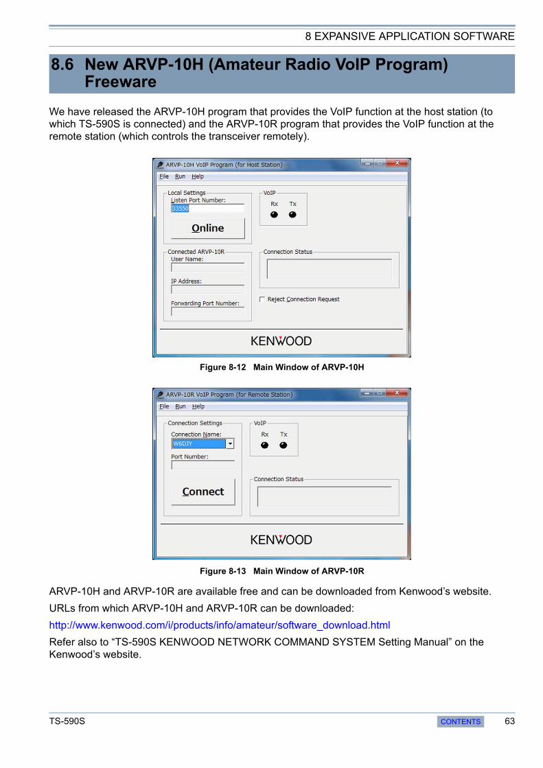
8 EXPANSIVE APPLICATION SOFTWARE
We have released the ARVP-10H program that provides the VoIP function at the host station (to which TS-590S is connected) and the ARVP-10R program that provides the VoIP function at the remote station (which controls the transceiver remotely).
Figure 8-12 Main Window of ARVP-10H
Figure 8-13 Main Window of ARVP-10R
ARVP-10H and ARVP-10R are available free and can be downloaded from Kenwood’s website.
URLs from which ARVP-10H and ARVP-10R can be downloaded:
http://www.kenwood.com/i/products/info/amateur/software_download.html
Refer also to “TS-590S KENWOOD NETWORK COMMAND SYSTEM Setting Manual” on the Kenwood’s website.
8.6 New ARVP-10H (Amateur Radio VoIP Program) Freeware
TS-590S CONTENTS 63

8 EXPANSIVE APPLICATION SOFTWARE
ARVP-10H and ARVP-10R enable a voice signal to be sent and received over LAN or the Internet.
Configure the necessary settings to use ARVP-10H.
Select “User Settings” from the File pulldown menu and click the “Add...” button in the User Settings dialog box and the Setup User dialog box will appear, In Setup User dialog box, you can set the user name and password.
Figure 8-14 Setup User Dialog Box (ARVP-10H)
To disable the user temporarily, click on the User is disabled checkbox.
To deny a connection request from all users temporarily, click on the Reject connection request checkbox in the main window.
To place ARVP-10H online, after above setting is complete, click the “Online” button in the main window.
To take ARVP-10H offline, click the “Offline” button in the main window.
8.6.1 Basic Functions
8.6.2 Setup of ARVP-10H (Host Station)
8.6.3 Making ARVP-10H (host station) Online or Offline
64 CONTENTS TS-590S
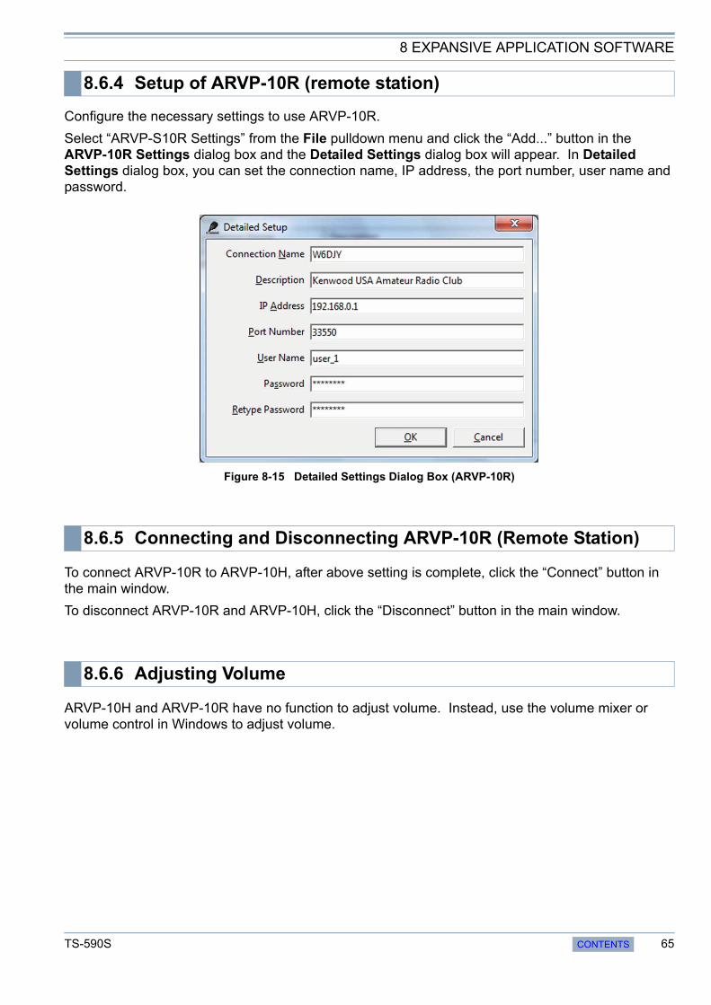
8 EXPANSIVE APPLICATION SOFTWARE
Configure the necessary settings to use ARVP-10R.
Select “ARVP-S10R Settings” from the File pulldown menu and click the “Add...” button in the ARVP-10R Settings dialog box and the Detailed Settings dialog box will appear. In Detailed Settings dialog box, you can set the connection name, IP address, the port number, user name and password.
Figure 8-15 Detailed Settings Dialog Box (ARVP-10R)
To connect ARVP-10R to ARVP-10H, after above setting is complete, click the “Connect” button in the main window.
To disconnect ARVP-10R and ARVP-10H, click the “Disconnect” button in the main window.
ARVP-10H and ARVP-10R have no function to adjust volume. Instead, use the volume mixer or volume control in Windows to adjust volume.
8.6.4 Setup of ARVP-10R (remote station)
8.6.5 Connecting and Disconnecting ARVP-10R (Remote Station)
8.6.6 Adjusting Volume
TS-590S CONTENTS 65

8 EXPANSIVE APPLICATION SOFTWARE
To connect the TS-590S and a PC via a USB cable to control TS-590S, the virtual COM port driver needs to be installed on the PC.
URLs from which virtual COM port driver can be downloaded:
http://www.kenwood.com/i/products/info/amateur/software_download.html
If you connect the TS-590S and a PC using an RS-232C cable, the virtual COM port driver does not need to be installed.
Also, if you connect the TS-590S and a PC via a USB cable and you use only ARUA-10, the virtual COM port driver does not need to be installed either. If you use only the built-in USB sound function of the TS-590S, the function behaves using the Window’s standard driver.
To view the COM port number to which the virtual COM port driver has assigned the USB port of the TS-590S, open Windows Device Manager and check “Port (COM and LPT)”. Locate the entry named “Silicon Labs CP210x USB to UART Bridge (COMxx)” and “xx” in the “COMxx” represents the COM port number assigned by the current virtual COM port driver.
In the example of Figure 8-16, you can see the indication of “Silicon Labs CP210x USB to UART Bridge (COM4)”. In this case, “COM4” is the COM port number assigned by the current virtual COM port driver.
Figure 8-16 Device Manager
While the TS-590S and a PC are connected via a USB cable, the COM port number is changed if the USB port is switched to another USB port. To view the current COM port number, follow the above procedure again.
8.7 New Virtual COM Port Driver
66 CONTENTS TS-590S
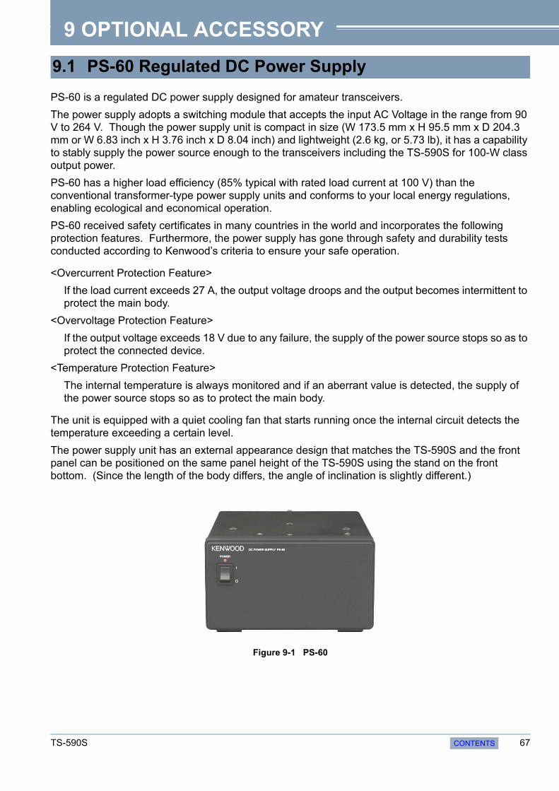
9 OPTIONAL ACCESSORY
PS-60 is a regulated DC power supply designed for amateur transceivers.
The power supply adopts a switching module that accepts the input AC Voltage in the range from 90 V to 264 V. Though the power supply unit is compact in size (W 173.5 mm x H 95.5 mm x D 204.3 mm or W 6.83 inch x H 3.76 inch x D 8.04 inch) and lightweight (2.6 kg, or 5.73 lb), it has a capability to stably supply the power source enough to the transceivers including the TS-590S for 100-W class output power.
PS-60 has a higher load efficiency (85% typical with rated load current at 100 V) than the conventional transformer-type power supply units and conforms to your local energy regulations, enabling ecological and economical operation.
PS-60 received safety certificates in many countries in the world and incorporates the following protection features. Furthermore, the power supply has gone through safety and durability tests conducted according to Kenwood’s criteria to ensure your safe operation.
<Overcurrent Protection Feature>
If the load current exceeds 27 A, the output voltage droops and the output becomes intermittent to protect the main body.
<Overvoltage Protection Feature>
If the output voltage exceeds 18 V due to any failure, the supply of the power source stops so as to protect the connected device.
<Temperature Protection Feature>
The internal temperature is always monitored and if an aberrant value is detected, the supply of the power source stops so as to protect the main body.
The unit is equipped with a quiet cooling fan that starts running once the internal circuit detects the temperature exceeding a certain level.
The power supply unit has an external appearance design that matches the TS-590S and the front panel can be positioned on the same panel height of the TS-590S using the stand on the front bottom. (Since the length of the body differs, the angle of inclination is slightly different.)
Figure 9-1 PS-60
9.1 PS-60 Regulated DC Power Supply
TS-590S CONTENTS 67

9 OPTIONAL ACCESSORY
Adopts a PFC Circuit that does not Produce Harmonics in an AC Rectifier Circuit
A switching power supply typically produces large harmonics in the rectifier circuit by its switching operation which compromises the phase factor and may cause noise and other disturbances to external devices due to the harmonics that are reflected back to the AC input side.
PS-60 incorporates a PFC-rectifier circuit that produces a rectified waveform close to a sine wave and prevents a compromise of phase factor and disturbances caused by harmonics.
Miniaturized Size by Employing an Interleaved Switching Scheme
By turning On and Off the FET switches on the master and slave sides alternately, the burden on each element is lessened and reliability is improved.
In the switching circuit, a full-wave current resonance type PFM control circuit is adopted to alternately turn On and Off two FETs in a 50% duty cycle. By defining a certain period of time after both FETs are turned Off, a soft switching operation, in which no current is made to flow at the point of switchover, is made possible to reduce noise.
Figure 9-2 Comparing Rectification Waveforms
A high switching frequency (about 500 kHz) is chosen to enable miniaturization of the transformer for highly-efficient DC conversion.
The DC output voltage after the conversion is monitored by the detection circuit to be compared with the reference voltage in the PFM control circuit in order to control the switching frequency for stabilizing the output voltage. If an overvoltage is detected, the switching of power source stops so as to suspend the DC output.
Also, output current is monitored by the detection circuit and if an overcurrent is detected, the switching frequency is shifted to droop the output voltage and the operation is transited to produce intermittent output.
Figure 9-3 Circuit Diagram
9.2 Rectifier Circuit
9.3 Switching Circuit, Constant-voltage Circuit and Protection Circuit
68 CONTENTS TS-590S


Version 1.00 May 15, 2011


![TS-590S SG PC CONTROL COMMAND Reference Guide · [TS-590S / TS-590SG common] Parameters: P1 0: ANT1 1: ANT2 9: No change P2 0: RX ANT is not used 1: RX ANT is used 9: No change P3](https://static.documents.pub/doc/80x56/5f580fd963ec2d417423089a/ts-590s-sg-pc-control-command-reference-guide-ts-590s-ts-590sg-common-parameters.jpg)


