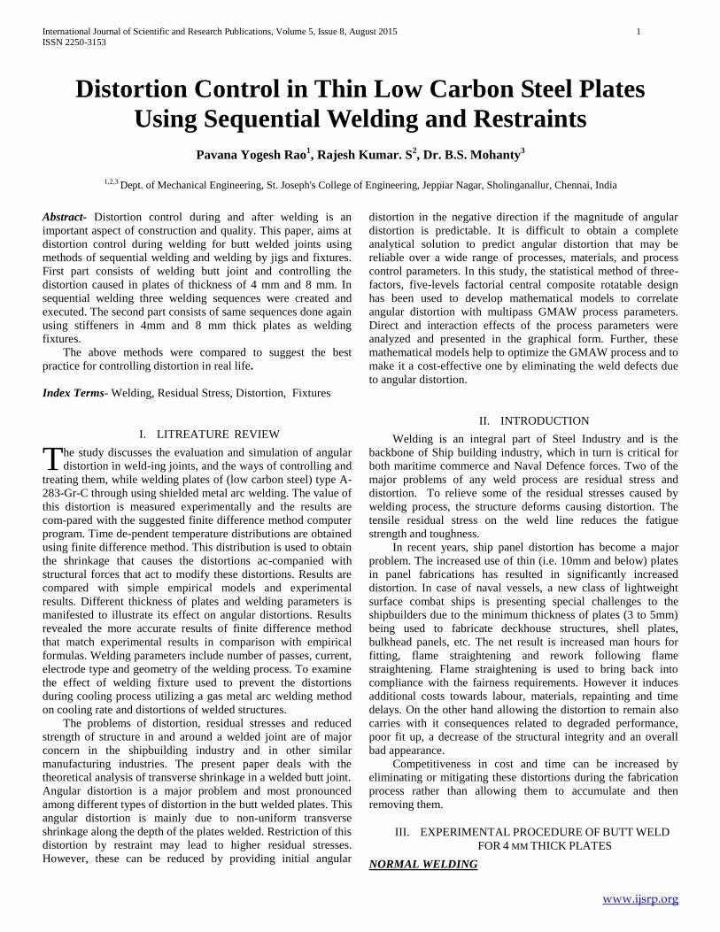
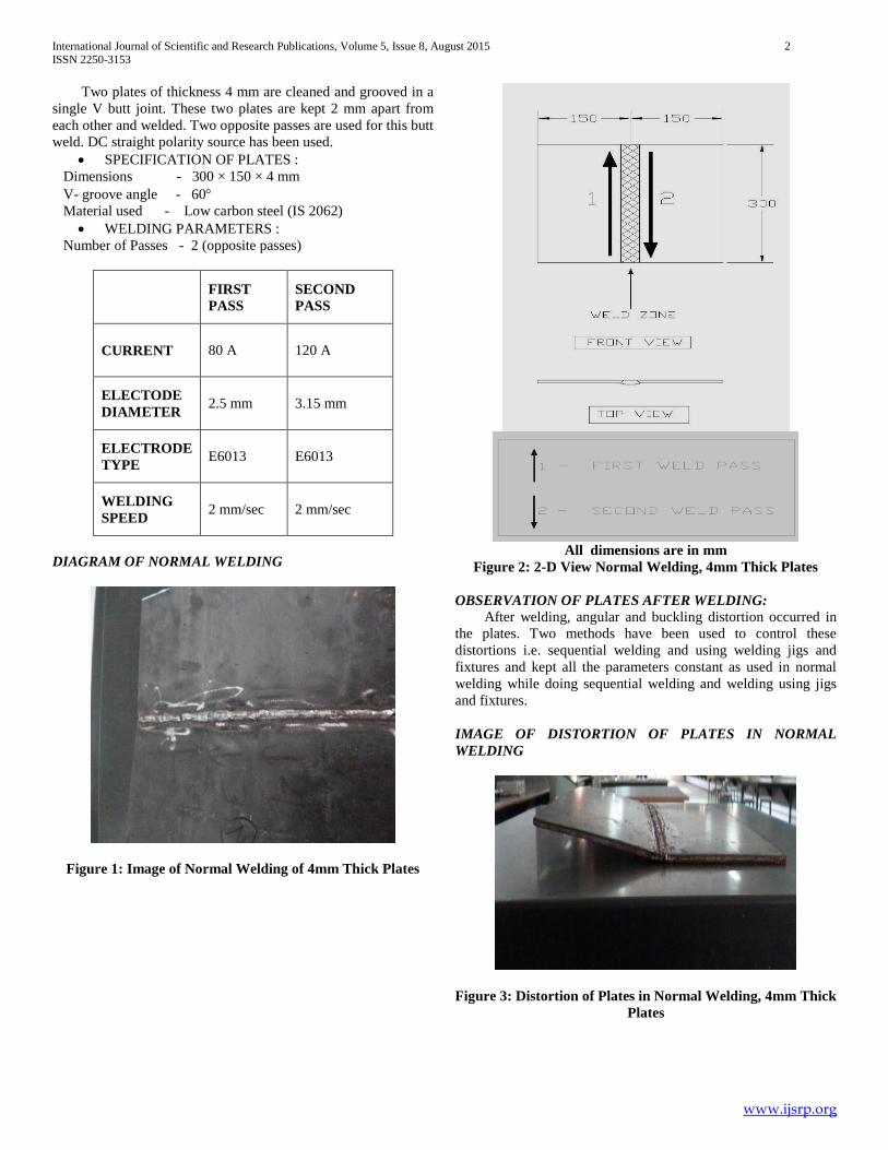
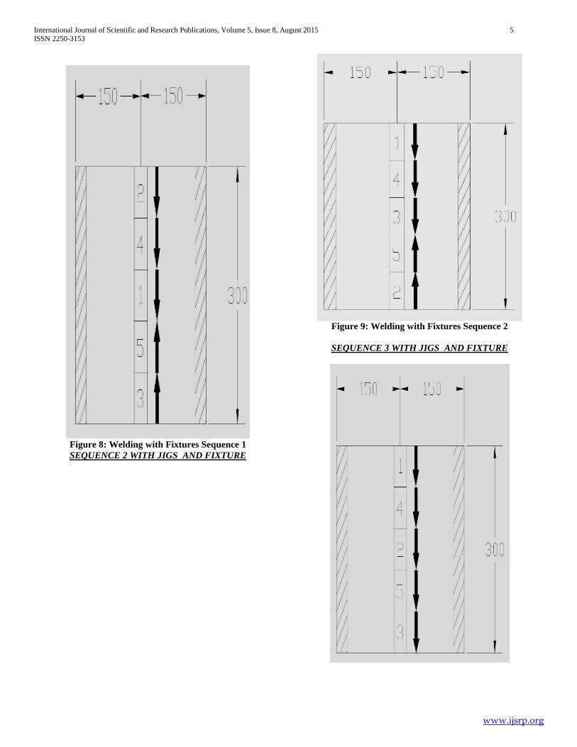
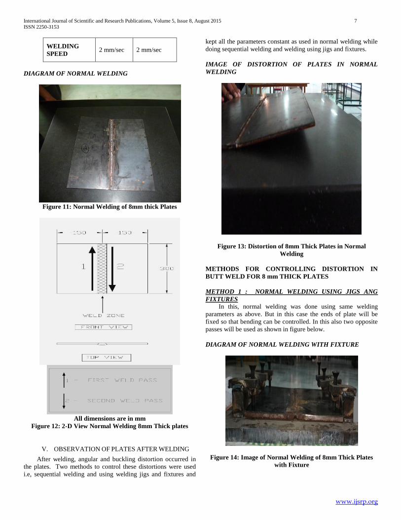
Distortion control during and after welding is an important aspect of construction and quality. This paper, aims at distortion control during welding for butt welded joints using methods of sequential welding and welding by jigs and fixtures. First part consists of welding butt joint and controlling the distortion caused in plates of thickness of 4 mm and 8 mm. In sequential welding three welding sequences were created and executed. The second part consists of same sequences done again using stiffeners in 4mm and 8 mm thick plates as welding fixtures.
International Journal of Scientific and Research Publications, Volume 5, Issue 8, August 2015 1 ISSN 2250-3153 www.ijsrp.org Distortion Control in Thin Low Carbon Steel Plates Using Sequential Welding and Restraints Pavana Yogesh Rao 1 , Rajesh Kumar. S 2 , Dr. B.S. Mohanty 3 1,2,3 Dept. of Mechanical Engineering, St. Joseph's College of Engineering, Jeppiar Nagar, Sholinganallur, Chennai, India Abstract- Distortion control during and after welding is an important aspect of construction and quality. This paper, aims at distortion control during welding for butt welded joints using methods of sequential welding and welding by jigs and fixtures. First part consists of welding butt joint and controlling the distortion caused in plates of thickness of 4 mm and 8 mm. In sequential welding three welding sequences were created and executed. The second part consists of same sequences done again using stiffeners in 4mm and 8 mm thick plates as welding fixtures. The above methods were compared to suggest the best practice for controlling distortion in real life. Index Terms- Welding, Residual Stress, Distortion, Fixtures I. LITREATURE REVIEW he study discusses the evaluation and simulation of angular distortion in weld-ing joints, and the ways of controlling and treating them, while welding plates of (low carbon steel) type A- 283-Gr-C through using shielded metal arc welding. The value of this distortion is measured experimentally and the results are com-pared with the suggested finite difference method computer program. Time de-pendent temperature distributions are obtained using finite difference method. This distribution is used to obtain the shrinkage that causes the distortions ac-companied with structural forces that act to modify these distortions. Results are compared with simple empirical models and experimental results. Different thickness of plates and welding parameters is manifested to illustrate its effect on angular distortions. Results revealed the more accurate results of finite difference method that match experimental results in comparison with empirical formulas. Welding parameters include number of passes, current, electrode type and geometry of the welding process. To examine the effect of welding fixture used to prevent the distortions during cooling process utilizing a gas metal arc welding method on cooling rate and distortions of welded structures. The problems of distortion, residual stresses and reduced strength of structure in and around a welded joint are of major concern in the shipbuilding industry and in other similar manufacturing industries. The present paper deals with the theoretical analysis of transverse shrinkage in a welded butt joint. Angular distortion is a major problem and most pronounced among different types of distortion in the butt welded plates. This angular distortion is mainly due to non-uniform transverse shrinkage along the depth of the plates welded. Restriction of this distortion by restraint may lead to higher residual stresses. However, these can be reduced by providing initial angular distortion in the negative direction if the magnitude of angular distortion is predictable. It is difficult to obtain a complete analytical solution to predict angular distortion that may be reliable over a wide range of processes, materials, and process control parameters. In this study, the statistical method of three- factors, five-levels factorial central composite rotatable design has been used to develop mathematical models to correlate angular distortion with multipass GMAW process parameters. Direct and interaction effects of the process parameters were analyzed and presented in the graphical form. Further, these mathematical models help to optimize the GMAW process and to make it a cost-effective one by eliminating the weld defects due to angular distortion. II. INTRODUCTION Welding is an integral part of Steel Industry and is the backbone of Ship building industry, which in turn is critical for both maritime commerce and Naval Defence forces. Two of the major problems of any weld process are residual stress and distortion. To relieve some of the residual stresses caused by welding process, the structure deforms causing distortion. The tensile residual stress on the weld line reduces the fatigue strength and toughness. In recent years, ship panel distortion has become a major problem. The increased use of thin (i.e. 10mm and below) plates in panel fabrications has resulted in significantly increased distortion. In case of naval vessels, a new class of lightweight surface combat ships is presenting special challenges to the shipbuilders due to the minimum thickness of plates (3 to 5mm) being used to fabricate deckhouse structures, shell plates, bulkhead panels, etc. The net result is increased man hours for fitting, flame straightening and rework following flame straightening. Flame straightening is used to bring back into compliance with the fairness requirements. However it induces additional costs towards labour, materials, repainting and time delays. On the other hand allowing the distortion to remain also carries with it consequences related to degraded performance, poor fit up, a decrease of the structural integrity and an overall bad appearance. Competitiveness in cost and time can be increased by eliminating or mitigating these distortions during the fabrication process rather than allowing them to accumulate and then removing them. III. EXPERIMENTAL PROCEDURE OF BUTT WELD FOR 4 MM THICK PLATES NORMAL WELDING T
Transcript
International Journal of Scientific and Research Publications, Volume 5, Issue 8, August 2015 1 ISSN 2250-3153
www.ijsrp.org
Distortion Control in Thin Low Carbon Steel Plates
Using Sequential Welding and Restraints
Pavana Yogesh Rao1, Rajesh Kumar. S
2, Dr. B.S. Mohanty
3
1,2,3 Dept. of Mechanical Engineering, St. Joseph's College of Engineering, Jeppiar Nagar, Sholinganallur, Chennai, India
Abstract- Distortion control during and after welding is an
important aspect of construction and quality. This paper, aims at
distortion control during welding for butt welded joints using
methods of sequential welding and welding by jigs and fixtures.
First part consists of welding butt joint and controlling the
distortion caused in plates of thickness of 4 mm and 8 mm. In
sequential welding three welding sequences were created and
executed. The second part consists of same sequences done again
using stiffeners in 4mm and 8 mm thick plates as welding
fixtures.
The above methods were compared to suggest the best
practice for controlling distortion in real life.
Index Terms- Welding, Residual Stress, Distortion, Fixtures
I. LITREATURE REVIEW
he study discusses the evaluation and simulation of angular
distortion in weld-ing joints, and the ways of controlling and
treating them, while welding plates of (low carbon steel) type A-
283-Gr-C through using shielded metal arc welding. The value of
this distortion is measured experimentally and the results are
com-pared with the suggested finite difference method computer
program. Time de-pendent temperature distributions are obtained
using finite difference method. This distribution is used to obtain
the shrinkage that causes the distortions ac-companied with
structural forces that act to modify these distortions. Results are
compared with simple empirical models and experimental
results. Different thickness of plates and welding parameters is
manifested to illustrate its effect on angular distortions. Results
revealed the more accurate results of finite difference method
that match experimental results in comparison with empirical
formulas. Welding parameters include number of passes, current,
electrode type and geometry of the welding process. To examine
the effect of welding fixture used to prevent the distortions
during cooling process utilizing a gas metal arc welding method
on cooling rate and distortions of welded structures.
The problems of distortion, residual stresses and reduced
strength of structure in and around a welded joint are of major
concern in the shipbuilding industry and in other similar
manufacturing industries. The present paper deals with the
theoretical analysis of transverse shrinkage in a welded butt joint.
Angular distortion is a major problem and most pronounced
among different types of distortion in the butt welded plates. This
angular distortion is mainly due to non-uniform transverse
shrinkage along the depth of the plates welded. Restriction of this
distortion by restraint may lead to higher residual stresses.
However, these can be reduced by providing initial angular
distortion in the negative direction if the magnitude of angular
distortion is predictable. It is difficult to obtain a complete
analytical solution to predict angular distortion that may be
reliable over a wide range of processes, materials, and process
control parameters. In this study, the statistical method of three-
factors, five-levels factorial central composite rotatable design
has been used to develop mathematical models to correlate
angular distortion with multipass GMAW process parameters.
Direct and interaction effects of the process parameters were
analyzed and presented in the graphical form. Further, these
mathematical models help to optimize the GMAW process and to
make it a cost-effective one by eliminating the weld defects due
to angular distortion.
II. INTRODUCTION
Welding is an integral part of Steel Industry and is the
backbone of Ship building industry, which in turn is critical for
both maritime commerce and Naval Defence forces. Two of the
major problems of any weld process are residual stress and
distortion. To relieve some of the residual stresses caused by
welding process, the structure deforms causing distortion. The
tensile residual stress on the weld line reduces the fatigue
strength and toughness.
In recent years, ship panel distortion has become a major
problem. The increased use of thin (i.e. 10mm and below) plates
in panel fabrications has resulted in significantly increased
distortion. In case of naval vessels, a new class of lightweight
surface combat ships is presenting special challenges to the
shipbuilders due to the minimum thickness of plates (3 to 5mm)
being used to fabricate deckhouse structures, shell plates,
bulkhead panels, etc. The net result is increased man hours for
fitting, flame straightening and rework following flame
straightening. Flame straightening is used to bring back into
compliance with the fairness requirements. However it induces
additional costs towards labour, materials, repainting and time
delays. On the other hand allowing the distortion to remain also
carries with it consequences related to degraded performance,
poor fit up, a decrease of the structural integrity and an overall
bad appearance.
Competitiveness in cost and time can be increased by
eliminating or mitigating these distortions during the fabrication
process rather than allowing them to accumulate and then
International Journal of Scientific and Research Publications, Volume 5, Issue 8, August 2015 9
ISSN 2250-3153
www.ijsrp.org
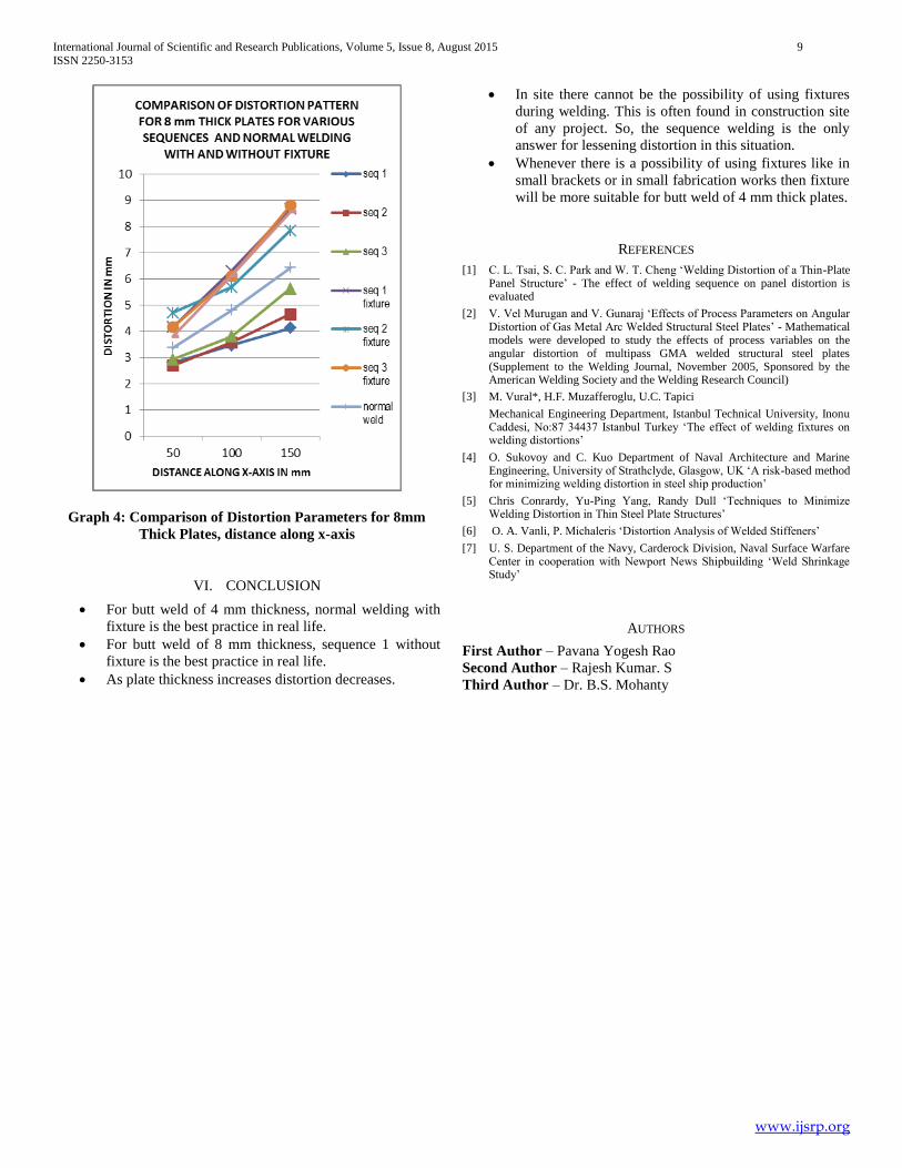
Graph 4: Comparison of Distortion Parameters for 8mm
Thick Plates, distance along x-axis
VI. CONCLUSION
For butt weld of 4 mm thickness, normal welding with
fixture is the best practice in real life.
For butt weld of 8 mm thickness, sequence 1 without
fixture is the best practice in real life.
As plate thickness increases distortion decreases.
In site there cannot be the possibility of using fixtures
during welding. This is often found in construction site
of any project. So, the sequence welding is the only
answer for lessening distortion in this situation.
Whenever there is a possibility of using fixtures like in
small brackets or in small fabrication works then fixture
will be more suitable for butt weld of 4 mm thick plates.
REFERENCES
[1] C. L. Tsai, S. C. Park and W. T. Cheng ‘Welding Distortion of a Thin-Plate Panel Structure’ - The effect of welding sequence on panel distortion is evaluated
[2] V. Vel Murugan and V. Gunaraj ‘Effects of Process Parameters on Angular Distortion of Gas Metal Arc Welded Structural Steel Plates’ - Mathematical models were developed to study the effects of process variables on the angular distortion of multipass GMA welded structural steel plates (Supplement to the Welding Journal, November 2005, Sponsored by the American Welding Society and the Welding Research Council)
[3] M. Vural*, H.F. Muzafferoglu, U.C. Tapici
Mechanical Engineering Department, Istanbul Technical University, Inonu Caddesi, No:87 34437 Istanbul Turkey ‘The effect of welding fixtures on welding distortions’
[4] O. Sukovoy and C. Kuo Department of Naval Architecture and Marine Engineering, University of Strathclyde, Glasgow, UK ‘A risk-based method for minimizing welding distortion in steel ship production’
[5] Chris Conrardy, Yu-Ping Yang, Randy Dull ‘Techniques to Minimize Welding Distortion in Thin Steel Plate Structures’
[6] O. A. Vanli, P. Michaleris ‘Distortion Analysis of Welded Stiffeners’
[7] U. S. Department of the Navy, Carderock Division, Naval Surface Warfare Center in cooperation with Newport News Shipbuilding ‘Weld Shrinkage Study’