AD-764 054 INFLUENCE OF COMPRESSIVE STRENGTH AND WALL THICKNESS ON BEHAVIOR OF CONCRETE CYLINDRICAL HULLS UNDER HYDROSTATIC LOADING N. D. Albertsen Naval Civil Engineering Laboratory L A Prepared for: Naval Facilities Engineeriag Command June 1973 DISTRIBUTED BY: Nath.! Technical Ilmutha Service U. S. DEPARTMENT OF COMMERCE 5285 Port Royal Road, Springfield Va. 22151 ,.w
Transcript
AD-764 054
INFLUENCE OF COMPRESSIVE STRENGTHAND WALL THICKNESS ON BEHAVIOR OFCONCRETE CYLINDRICAL HULLS UNDERHYDROSTATIC LOADING
N. D. Albertsen
Naval Civil Engineering Laboratory L
A
Prepared for:
Naval Facilities Engineeriag Command
June 1973
DISTRIBUTED BY:
Nath.! Technical Ilmutha ServiceU. S. DEPARTMENT OF COMMERCE5285 Port Royal Road, Springfield Va. 22151
,.w
Tuchnw,c Rep ort
09NAVAL I2ACILIT!ES ENGINEERING COMMAND
Juim i9/3
NAVAL CIVIL ENGINEERING LABORATORY
Port HuwmnuoieCdblutnia 93043
INFLUENCE OF
COMPRESSIVE STRENGTH
AND WALL THICKNESS
ON BEHAVIOR OF
CONCRETE CYLI1NDRICAL
HULLS UNDER
HYDROSTATIC LOADING
By
N- D. Albertsen-
Ajiprovod for 1public reIeeip,
distribulion unlifni!,d.
NAII)flAt.I-HI.iI~VN\ IO)N rSERViCE
INFLUENCE OF COMPRESSIVE STRENGTA AND WALLTHICKNESS ON BEHAVIOR OF CONCRETE CYLINDRICALHULLS UNDER HYDROSTATIC LOADING
Technical Report R-790
3.1610-1
N. D. AllwjrtsenA
Ii. ABSTRACT.
Sixteen unrrinfnrced, cylindri~cal concret'o hull modelS Of 16-inchXoutside diameter were subje~cted to external hydrostatic loading to deter- 1mine. the effect of concrete strength arid wall thickness on implosion andstrain behavior. The test results showed that an increase in concrete strengthof 70% produced an average increase in implosion pressure of 87Ao, whileincreases in hull wall thickness by factors of 2 and 6 produced increases inimplosion pressure by factors of approxiimTate~y 2 and 11, respectively.
Changes in concrete strength had little effect on strain behavior; however,strain magnitudes generally increased with increasing wall thicknes.. whencomparisons were made at a constant percentage of Pim, Design recoin-
mendlations are presented to aid in the design of cylindrical concrete hullsfor underwater use.
- .~.C- ES
Us. . - Approved tor public release; distribulion unlimited. l
Copies, avallable at the National Tochnical informatioin Service (NTIlS),A
-4 Sills Euildlng. 5285 P ori Roy al Road , Springfield. Va. 221 1 I
WIN
DOCUMENT CONTROL DATA. EL 1.01
Naval Civil Engineering Laboratory UnclasdfiedoPort Hueneme, California 93043
1 41.0041 I E r
INFLUENCE OF COMPRESSIVE STRENGTH AND WAILL THICKNESS ON BEHAVIOR OFCONCRETE CYLINDRICAL HULLS UNDER HYDROSTATIC LOADING
Final; July 1970 - April 1972LU XNO661 g79 .. mm
N. D. Albertsen
*NPR O1006 To1 V. TOTAL ftO 0? W*agg* Pb 00op efq
June 1973at C Oft IMAC T On 8U* Y NO. Vt0. 040t06 *Y0A6 411ON910T Nw1116111111
,. .oJ..C ,,o 3.1610-1
9 C.
to 011 taUTION , J0 LAT URNT
Approved for public release; distribution unlimited.
9'- IUPPLEM11INA*4V NOlE I.e*w:.w "YAMTV aCYV,
Nava', Facilities Engineering CommandAlexandria, VA 22332
Sixteen unreinforced, cylindrical concrete hull rr odels of 16-inch outside diameter were A
ssbjected to external hydrostatic loading to determine th,.- effect of concrete strength and wallthickness on implosion and strain behavior. The test results showed that an increase in concretestrength of 70% produced an average Increase in implosion pressure of 87%, while increases in hullwall thickness by factors of 2 and 6 produced increases i4 implosion pressure by factors of approxi-mutely 2 and 11, respectively. Chrnges in concrete strength had little effect on strain behavior;however, strain magnitudes generally increased with incrnasing wall thickness when comparisonswere mfade at a constant prcentage of Plm. Design reco,.nmendatlons are presented to aid in thedesign of cylindrical concrete hulls for underwater use.
DWWaIl o( iustmttot Inniirtw " ffa y h o t e-
in microfiche.
FORM IPAGE I I
DD ,40,$14-3 P UnclassiflidS/N 00o.o807.SS 1Icurlt' M so stlion
LIST OF SYMBOLS .. .. ...................... .......... 27
INTRODUCTION
Previous studies1"8 conducted at the Naval Civil EngineeringLaboratory (NCEL) have shown that concrete is an effective constructionmaterial for undersea pressure-resistant structures. Experiments on concretecylindrical hulls 5 . 7 with 16-inch outside diameters, 2-inch-thick walls, and8- to 128-inch lengths have established the influence of the length-to-outside-diameter, L/D., ratio and the end-closure stiffness on implosion pressure,strain magnitude, and strain distribution. Figure 1 shows that the thick walltheory based on Lame's equation conservativety predicts implosion pressurefor cylindrical concrete hulls with a wall-thickness-to-outside-diameter, t/DO,ratio of 0.125 and L/Do ratios from 0 to 8. The strain and implosion datafor these hulls indicate that the effects of hemispherical concrete end-closuresare minimal at a distance > 1 diameter from the edge of the cylinder, and,thus, cylinders with LID0 ratios greater than 2 can be considered to be infi-nitely long. Variations in end-closure stiffness did not cause a reduction inthe implosion pressure of cylindrical concrete hulls below values predictedby Lame's equation; however, rigid end-closures produced high shear strainsnear the closure which would be undesirable for structure subjected to long-term submergence.
The objective of this study was to determine experimentally therelationship between implosion prfsure, concrete strength, wall thickness,strain distribution, and strain magnitude in cylindrical concrete hulls subjectedto external hydrostatic loading.
Data from this experimental study were used to develop designguidelines so that safe and economical pressure-resistant cylindrical concretestructures can be designed for underwater applications.
EXPERIMENTAL PROGRAM
Experiment Design
Sixteen concrete cylindrical hulis having four different wallthicknesses and two concrete strengths were tested to implosion undersh-ort-term hydrostatic loading. The hulls had wall thicknesses of 1/2, 1,
2, and 3 inches (F igure 2) which correspond to t/D0 rat ios of 0.03 12, 0.0625,0. 1 2W,0 and 0. 18/5 AllI (,;ylindHelS were 16 incWS in outside diJameter anid 64inches long, each hard hemisfpherical concrete erid-closures of (lie sarine wall01ick'~eisis theII cylinder. Two hulls Of each Wall thickness v.ete made of con-
crete wVith a UniaXial coinpr ",sive strengfr , fC, 0! app!oximnately 6,000 psiand two of approxiiindteiy 10,000 psi- One hull of each concrete strengthand viall thickness was instrumented with electrical resistance strain gages.A sumnmary of IN,, desiyri Inforrintion for the cylindrical hit ;s Is given inTable I.
Z: 0.6 It -- 2 In.
spherical structu 'as, I
10.50
0.40\ II ~0 in
Q. etimated It/Do ratio -0A1250
0.30 - cylindrical sitructures, - __ _
11 itted curve
C
0. 10
E
0 1 2 3 4 5 6 7 8
Cylinder LengthiOutside Diameter, L/Do
Figure 1. Analytical prediction of implosion pressure (after Reference 5).
Fabrication of Specirnen3
All cylinders arid hemispherical end-closuiresI were cast in rigid metalmolds which had been machined to tolerances ot ± 1/32 inch. The cylindersand end-closujres were maide from a microconcrete mi.-. consisting of type I Iportland cement. San Gabriel River Wash Aggregate, and freshwater. Coni-crete strengths of approximately 6,000 and 10,000 psi were produced byvarying the water -to-cement ratio and the cure procedure. Table 2 gives them;Y' proporti J)ns and cure times, arid Table 3 gives the aqgregaice prioporlionswhich iremained the same for both mixes.
.2
Figure 2. Cylindrical test specimens with wall thicknesses ranging from 1/2 inch to3 inches.
After moist curing, the cylinders and end-closures were stored underroom conditions while being prepared for test. Hull preparation began witha light sandblasting of surfaces to expose surface voids and to remove lait nce.Small, shallow voids were filled with a cement-sand paste, while larger voidswere filled with an epoxy adhesive. The mating surfaces of the cylinders andend-closures were qround flat by rotating them on a flat plate covered withNo. 60 Silicon Carbide grit. Next the cylinders and hemispheres were water-proofed with a clear epoxy paint and bonded together with an epoxy adhesive.The final step in the specimen fabrication was to apply electrical resistancestrain gages. Figure 3 shows a cross section of a fabri:cae,,d cylindrical hull,and Figure 4 shows the strain gage layout for the hulls.
Test Procedure
The cylindrical hulls were tested in NCE1L's 72-inch pressure Vessei(F: iqire 51. The hills ,,',ere filled with wvater and ,ented! 'o oijtside the press(:re
Dwmn q C' tvi na~tst, 11 1e in vrskiý, p ~ IIa
Best Ava;h Cop-t0i7 CoF-1
constant rate ii-tut implosion occurred, Thle pressurizeationi rate was 20psi/min for the i6/2-inch-thick htills arid 100 psi/min for thp- i , 2-, atnd 3-inch-thick huls. At selected pressure InkletvalS, 0im0 Strdl gd(qUS were, interrogatodand the chdflqjf in voltillC of the specimen Wds recorded. Chiange ini vultirflLwas tineastred by colleclinq the wajtcr displaced under load frorn The hull'sinterior.
Table 1. Descriptiun of Cylindricaml Hulls
(All uvliInturs vere 64 inchici long d',c.16 tOncflus in otuilidL diinialcr.1
Cylinder ID0 T Il Noinii..l UnlaiJ~al Straii)Oýin~to' 1(.); Thick ne Coinpresbivit Strength (3u9ci on
1 f2- 1O-G 10,000 1 t3112-1 -N 0.0312 0.5 10.00 0
6.000 1 to 14112-6-N 6,000 0
1.1I1 0.000 1 to 34.1-10-N 0.0625~ 1.0 110,000 0
T61,000 1 to 141-6-N 6.000 0
2 10-C5 10,01)(A 1 to 3'2-I104 0.1250 2-0 10.000 02.6-6 6.000 1 to 1 A2 6-N~ 6.000 0
3-10IG 10,000 1 to 343-10ON 10.0)00 . 0
0.1875 3.06COio13.6-C .C o13-6 N ] I oo00 0
"J DtsiqnatiLc:i systuin is. Wasll thicknes% brinclhj' -- NoOinio -,;tIrmrltC strenigth (ksl)-Gaged or Not riaged hull.
SSetv F iguiu 4 lt, ;ocation of qaties.
I able 2. Mix Propuriti is and Ctinut Tif tis
Arpproxinotu Umaxial 1 WaI4e.tO-COIus-nt Aqjre'jate-to-Cenic-nt Cure Tirni in ApproximateComprerssive .Strength IAge at 'rest
of Mix (psi) (jby WL-ighl) Fili (by. wui'Jhl Ratio 100% RI- (days) (da~y 0
V132 Inch of the some wall thickness as thecylinder
water proofing epoxy, T1132 inch
strai gaps64 in. .t 114strain gages
Wall Thicknesses
4in.)
tO.5 - 112 In. 1116
t.5 - 1/ in. ± 1/16
- t2.0 - '- In. ± 1/16
t 3 .0 ' 3 in. ± 1116
Mtrain gage lead wires pottedwith epoxy adhesive - -16 in. ± 1/32
Figure 3. Cross-section of cylindrical hull with hemispherica, end-closures.
5N
Ul•Cie
Gap type: BLH RA4, A, -_
23 to 28
27 to 0r~9 to
60D
Cylinder Unfolded to Show Strain Gage Layout
26 -30 34 14 I. -T is -22 -mldlengt,
13 1-2- 4- " -of hull
18 +12 ---
'- -4'"
25 29 33 6 Al" 17 21
S6 'q
24 28 32 4 2011-~---I- 2
3 ___t4"23 27 31 2 _114" lb 19
I .- bottom hemisphere
1/2" 1/2" cylinder joint
Figure 4. Strain gage 1yout tor the cylindrical hulls.
Tablo 3. Agyrmqate Proportions
Sieve Size DesignationPercen, Vetainod
Passing Rotained
No. 4 No. 8 21.6No. 8 No. 16 20.J
No. 16 No. 30 14.7
No.30 No. 50 10.3No. 50 No. 100 7.3
No. 100 pail 17.3
6
1(I:-I i : 4 t I l1 1 lllI l -10 1 1 1 l 1 c e l l .v t.,. o
TEST RESULTS AND DISCUSSION
Mode of Failure
I 1n-pv(Iir. ! ( ot theu hoill 101t Wr w-test rj i':Xat lh tnate Li I c ct rwrd,
1(11101 inq on. o t hi ckOiv~-ssh '1011r hu V Jwx re:)r byn;SH i lrr t dE
ui u1'i IiI' Iby )ritiiI o I ,vi lknsi Implodedt Ow tycom~e r (,1in
j t I 'r rI n l(t , jr ý) fS I V ¶-twir ji ~t~i e e i Tt k! r ( ;.i tI I ru i s it i c;i Iir t k) 1d t h Iin iI
I" tIni rIf 1!`1 t I i W( ton T IIr itr 14 l' It nij )4 'Tt Fr IS;~ It It ' it t dl I i t n-JI t i w
eI r I, t Ii . c I if I)( If ) Ie )rrtpim T !t -k ui~ t i fe i t r l A tr y ti 2 1( 4 -) dft. '1ree mth'tI t n yit tr xi f, o iihi ')" h ýT)fkI1t (tI J1ý,i
T)II'f Id j I I I Fn l
Best Available Copy
The shear planes that were evident in the thicker hulls were completelyabsent from the 1/2-inch-thick hulls. These hulls shattered into many piecesat failure (Figure 7), which made it impossible to locate the imitial point offailure. The mode of failure for these thin specimens appeared to be bybuckling, because at failure the maximum wall stresses ranged from 53 to62 percent of the uniaxial compressive strength of the concrete (Tab c 4).
"a Wall thickries.e- of 1/2, 1,2, and 3 Inches correspond to t/DO ratios of 0.0312. 0.0132C. 0.1250.and 0.1875, respectively.
b Aver•ae of six 3 x 6-inch control cylinders tested In unlxial compression (sam the Appendix).
No evidence was found in the debris from the tested specimens toindicate the presence of in-plane cracking. In-plane cracking is the develop-ment of cracks parallel to the maximum principal stresses (or in-the-plane
of the wall) and has been found by other investigators working with concrete
spherical4 and cylindrical 6 '11 hulls under biaxial stresses.
I mplosion
Implosion performrnce was evaluated by comparing values for the
ratio of implosion pressure to concrete strength, PI./f,." the implosion test
results are presented in Table 4. This ratio accounts for small variations in
concrete strength. Figure 8 shows the best fit relationship between Pi./f'and tVD. for the test results. The empirical equation which defines thle bestfit curve is:
Pim t- 2.05 - 0.028 (1)
C Do
for 0.0312 < t/D < 0.1875. Equation I can be used to oredict the implosionpressure of cylindrical concrete hulls under hydrostatic loading.
The implosion pressure for concrete cylindrical hulls subjected to
hydrostatic loading can be estimated by c!assical equations. Lame's equation
can be uscd to estimate the implosion pressure of cylindrical hulls which fail
10
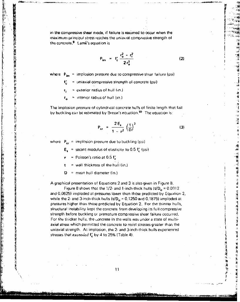
in the compressive shear niode, if failure is assumed to iccur when themaximum principal stress reaches the uniaxial compressive strength ofthe concrete. 9 Lam6's equation is
r2 2f' L. (2)
r2 r2
where Pk = implosion pressure due to compressive shear failure (psi)
Sf, = uniaxial compressive strength of concrete (psi) 4
Sr, exterior radius of hul! (in.)
r. interior radius of hull (in.)
The implosion pressure of cylindrical concrete hulls of finite length that failSby buckling can be estimated by Bresse's equation.10 The equation is:
FT P = - (3)
where Pcr = implosion pressure due to buckling (psi)
ES = secant modulus of elasticity to 0.5 f, (psi)
P = Poisson's ratio at 0.5 f,'
t wall thickness of the huli (in.)
D mean hull diameter (in.)
A graphical presentation of Equations 2 and 3 is also given in Figure 8.Figure 8 shows that the 1/2- and 1 -inch-thick hulls (t/Do = 0.0312
and 0.0625) imploded at pressures lower than those predicted by Equation 2,while the 2- and 3-inch-thick hulls (t/D0 = 0.1250 aid 0.1875) imploded atpressures higher than those predicted by Equation 2. For the thinner hulls,structural instability kept the concrete from developing its full compressiveistrength before buckling or premature compressive shear failure occured.For the thicker hul~s, the .oncrete in the walls was under a state of multi-axial stress which permitted the concrete to resist stresses greater than the
uniaxial strength. At implosion, the 2- and 3-inch-thick hulls experiencedstresses that exceeded fV by 4 to 25% (Table 4).
C i
ji
S " -- •,•' ,L • ;" , . "T
49c.1
iir006
F LP 'I
L Ull
?#/Wld 144uoj)S oI6Xo/iUO3ImIUJ uoIIoodwh 1
12
Stai
w I SrainFigures 9 Oirouq~i 18 shc qv the strain and radial displacement data -for the instrumented hulls'. Theso data helped to define the influence uf wallthickness, concrete strength, and end-closuie ef fects orn the behavior of thehulls.
r Figures 9 through 12 show the exterior hoop strain behavior forop6cimens of each wall thickness. These figures iditethat the hulls reactedto increasing hydrostatic pressure in approximately the same manner rugardlessof concrete strength. Within one outside diameter (16 inches) Iron: the edt~leof the cylinder, large variations in strain magnitude were present; these varia-tions in strain magnitude increased with increased pressure, Beyond 16 inchesthe strain magnitudes became somewhat uniform. This behavior was causedby the stiffness mismatch that existed between the stifft hemispherical end-closure and the more compliant cylinder; this is consistent with behaviorobserved in References 5 and 7.
The hoop strain data also show that as the hulls became thicker,4N the strair' magnitude tended to become greater at a constant percentage of
Pk,,. This behavior is reasonable because the concrete in the thicker walled
the thinner walled hulls. Table 5 shows that at 0.95 PIM the theoretical
radial stress component on a midwiall elem-ent increased from 3 to 26% ofthe hoop stress compon'ent and from 6 to 41% of the axial stress componentwhen the wallI thickness was increased f rom 1/2 to 3 inches. I t is known thatconcrete under a high triaxial loading state can sustain higher stresses arid
9 strains than concrete under a low triaxial (or biaxial/uniaxial) loading stale.
-0--- Average hoop strain for specimen 3-10-Gas indicated by displacedvaiter
Lii
-750.Concrete strength f 10,000 psi
-.... Concrete st:ength % 6,000 psi
No dole taken uetween 8 arid 24
inches rain jloint
a"--.,,..... .,- " 0.95 PiM
C -
.250 U.96 im
. 0.3i
loint 4 8 12 16 20 24 28 32
Oistance From Bottom Joint (in.)
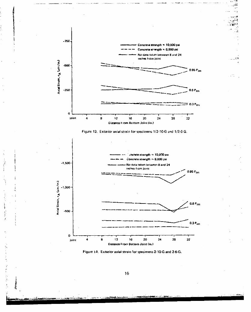
Figure 13. Exteaior axial strain for specimens 1/2-10-G and 1/2-6-G.
- rncrete strength ft 10.0030 psi
Concrete strength -' 6,000 psi
-1,500 " No data taken between 8 and 24
inc;hes frn Jointm
". 0.96 Pim
*-1.000-
i: • 0.6 OPin
. -500
'•--'"•"0.3 Pim
0 "r"-"- - , -- ' t----"--- T-
joint 4 8 12 163 20 24 28 ;32
SODistance From Bottom Joint (in.)
Figure 14. Exterior axial strain for specimens 2-10-G and 2-6.G.
* 16
- -J . I
4 4
2 2i
0 0.306, 4 4 ...
3 3
SPreglu~. LgvelI (% of Pit
)S(31 1/2 in. from "edge of cylinder. (b) 8 in. from edge of cylinder. .
So ,,-0.9o
Figure 15. Radial displacement of the exterior surface of specimen 1/2-10-G.
The change-in-volurne data were converted to average exterior hoop = .
strain by the thick wall theory. These calculated average values for hoop•\,;vatn are ploi l in F-igures 9 through 12 at 0.95 Pim and serve as a check
• ~~on the strain gage data. i _Figures 13 and 14 show the axial strain behavior of 112- and 2-inch-
thick cylinders, respectively, These tigures are typica! for the behavior of all ; ;
the instrumented cylinders. in general, the axial strain at 8 inches from the •edge of the cylinder was .he same as that near the cylinder's midlength. No
distinct trends in axial strain behavior were found that could be atnributenh
to variations in concrete strength.
A1
4 4
I2 6 2
I ~Pronuee~ Levels M% of Pim)
0 ~0(a) 1/2 in. from edge of cylinder. 0.0(b) 8 in 'rom edge of cylinder.
a 0.60Q 0.95
41 Displacement Scale. Ii' x~ 10xt-2 in. 4
5 3 3
612 6' '2
(c) 16 in. from, edge of cylinder. (d) 32 in. from edge of cylinder
Figure 16. Radial displacement of the exterior surface of specimen 1-10-G.
Figures 15 through 18 show the radial displacement* of the exteriorsurface for the cylindrical hulls. These figures reveai some interesting patternsof be havior. At 1/2 and 32 inches from the edge of the. cylinder, all specimensremeined quite circular at all levels of pressure. At 8Band 16 inches from theedge, the I1- and 3-inch-thick sýpecirnens showed marked deviations from axialsymmetry and large amounts of out-of-roundness under load. The probable
ra s fcI It - a;-, OSI j52 Lt'.3SC US ~ ~ 'A.
initial out-of -roundness in the specimens combined with the influence ofthe stiffness mismatch hetween the hemispherical end-closure and the cylinder.
*Radial displacement isthe produJct of hoof) strain and radius to the 7,uirface of iuierest,
3 I6 2 NIIi4a) 1/2 in. from edge of cylinder. L0el 0%o im
oC (b) 8I.from edge of cylIinder.0 -0.30
--0.95
4 Displacement Scale. 1/8 In. - I1 10- 2n 4
6 /2 6
(c) 16 in. from edge of cylinder. (d) 32 in. from edge of cylinder.
Figure 17. Radial displacement of the exterior surfece of specimen 2-10-G.
DESIGN PROBLEM
Design a cylindrical concrete hull of 25-foot inside diamneter,100-foot length (cylinder portion only) arid 100,000-pound positive buoyancyfur long-term operation at a depth of 1,000 feet. As-sumne the use of hemni-spherical end-closures of the samne wall thickness as the cylinder and concreteof 7,000-psi urtiaxial compressive strength.
I4 J4
3 3
62 2
Pressure Levels 1% of Plm)
-0
(a) 1/2 in. from edge of cylinder. - 0.30 (b) 8 in. from edge of cylinder.- 0.60- 0.91
Displacement Scale, 1/8 in. I x 10-2 In.
4 ,4
626 2
(c) 16 in. from edge of cylinder (d) 32 in. from edge of cylinder.
Figure 18. Radial displacement of the exterior surface of specimen 3-10-G.
Because a buoyancy requiremenk is It-.rt of the example problem,
the first step is to determine cylinder w/all thicknes's based on buoyancy.
3g 1007r .2)(a) Displacement of hull.= 64(E D3 + 0
Next, it is necessary to chcck the design to be sure that there is asafety factor of at least 3 on the structure as it may be manned and used forIong4erm operations.
(a) P 0.028) (1)
= 7 x 10³ 2.05 58 0.02832.17 /
= 1,397 psiI ~I
(b) Convert 1,397 psi to depth of water in feet:
Implosion Depth = 1,397 x 2.24
3,130 ft
21
Wc afiety Facto Implosion DepthS. tor Operating Depth
3,11'30/1,000
3.13
Since. the safety factor is greater than 3.0, the wall thickness derivedthrough buoyancy considerations is, therefore, satisfactory. If the safetyfactor had turned out to he less than 3.0, then a concrete mix with a corn-pressive strength greater than the specified 7,000 psi would have been required.
lItthe structure's buoyancy is not of major concern, Figure 19 can beused to quickly determine the cylinder wall thickness needed for d given depthand factor of safety. To solve the example problem using F igure 19 as thedesign guide, the follGwing steps are requlirpd.
(is) Convert operating depth to pressure in psi:I
Pressure, P =1,000 ft x 1.,4463 =446 psiI
(b) Calculate P/f,':
P/fV ~ 0.064
[(c) Enter Figure 19 at P/f,' =0.064 and react acrc-SS Until thu 3.0factor of safety curve is intersected. Read out t/D. = 0.108
(d) Sit ice t -(Do - Dd1)2, t -~0. 108 DO' arid 0, 25.00 hi, then
Do =31.89 ft
t 3.44 ft
Note that the 'Nall tlrickris% obtained using Figuro 19 is slightly less;thin that obtained using Equation .3 and buoyancy considerations, This isbeCaulse depth controlled the desiyn of Figuie 19; the cesult is a structurethat has approximately 150,000 pounds miore buoyancy ihari the 100,000pounds specified in the example problem.
The final design of cylindrical concrete hulls for uISP ill the oceanwould have to include steel reinforcement to resist handling loc'Js; suchdesign mneasures Lanf be accomplished with conventional reinforce iprestr sseddesign techniques and are not included herein.
Figure 19. Design guideline for cylindrical concrete hulls wvith hemispherical* eiid-closures (based on Equation 1).
FINDINGS
1. The imploswon pressures for the concrete cylindrical hulls showed a dirctrelationship to increases in concrete s-zrcngth from 6,000 to 10,000 psi andto Increases in the ratio of wall thickness to outside diameter for vulues from0 0312 to 0. 1875. A linear empirical equation, Equation 1, was developedto predicl the implosirmn presstires.
2. Imrplosion pre~ssures rarigcd from 208 psi for the 1/2-inch-thick hulls of6,000-ps~i con1Crete strength to 3,930 psi for the 3-inch-thick hulls of 10,000-
psi concrete strc'rigth.3. rTvu modus of failure for the hulls were, observed: the 1/2-inch-thickhulls (t100 0.0312) failed by buckling, while the 11- 2-, and 3-inch-thick
a hulls (LDO 0.0625, 0.1250, and 0.1875) failed by compression shear typem.3tei ial failure.
3 4. Stram dita showed that end-closure etllects wcre minilmal beyond onleoutside diijme.tcr from the end-closure-to-cyhinder joint.
23
CONCLUSIONS
This study on the influence of concrete strength and wall thicknessand previous studies on the influence of cylinder length and end-closurestiffness have demonstrated that concrete is a predictable material forpressure-resistant cylindrical structuris. It is estimated that buoyant,cylindrical concrete structures will have applications to the ocean depthof 1,500 feet.
RECOMMENDATIONS
1. It is recommended that Equation 1 or Figure 19 be used as a guidelinefor the design of cylindrical concrete hulls for use under the sea.
f~ (2.05 ~--0.028)(1"00
where Pm = implosion pressure (psi)
f. = uniaxial compressive strength of concrete (psi)
t = wall thickness (ft)
Do = outside diFmeter (t)
2. It is recommended that the region between the end-closure-to-cylinderjoint and one outside diameter from the joint not be used for penetrations inconcrete cylindrical hulls if alternate locations are available. If thiis locationis used for a penetration, then an appropriate increase in the factor of safetyis recommended.'
ACKNOWLEDGMENTS
The author wishes to thank Mr. Harvey Haynes of the OceanStructures Division for his constant interest, encouragemenit and maiyhelpful suggestions. He also wishes to thank Mr. Philip Zubiate whosespecial eftorts in the fabrication of the test specimens allowed the timelycompletion of the work. 2
"The effect of penetrations in cylindt. it hulls is under study.
The test results from the 3 x 6-inch control cylinders for the cylindricalhulls are presented in Table A-1. The nominal 10,000-psi concrete strengthmix produced avc.rage values for f,, E., and P of 10,460 psi, 3.56 x 10⁶ psi,and 0.19, respectively; the nominal 6,000-psi concrete strength mix producedaverage values of 6,130 psi. 2.68 x 10⁶ psi, and 0.16, respectively, for .hesame three parameters. All hemispherical end-closures were made from ahigh-strength mix which had average values of 8,840 psi, 3.18 x 10⁶ psi, and0.17, respectively.
"rable A-1. Test Results for 3 x 6-Inch Control Cylinders
Specimen Compressivo Strength of Secant Modulus of Poissor's Agn at
Designation roncrete, fQ (psi) Eiasticityýa E, (psi x 106) Rntio'b 1 Test (day.)
1/2-10-N 10,700 3.47 0.18 101
112-10-G 10.900 3.85 0.18 124
S1t2-6-N 5,420 2.58 0.18 16
1/2-6-G 5,760 2.20 G.16 32
1-10.N 10.700 3.72 0.20 117
1-10-G 10.480 3.55 0.20 118
1-6-G 6,620 2.67 0.16 28
1-6-N 5.920 2.70 0.17 27
2-10.G 9,840 3.58 0.18 118
2-10-N 9,950 3.36 V.'9 124
2-6-N 6~,080 2.91 0.15 23
2-6-G 6,060 2.87 0.12 24
3-10.G 1 U,350 3.59 0.22 119
3-0O-N 10,80U 3.40 0.14 119
3.6-N 7,000 2.80 0.15 27
3-6.G 6,200 2.66 0.21 27
"a Average of two 3 x 6-Ico control cylindors to 0.5 fQ.b Averagi of two 3 x 5-inch control cylinders.
25
4
REFERIENCIEF
* ~1. Naival Civil Engineering Laboratory. TVechnical Report R-b`17: Behaviorof spherical concreto hulls under hydrostatic loading, pt. 1 . Exploratoryinvei;tigdti( nl, by J. D. Stachiw and K. 0. Gray. Port Huenerne. Calif., Mar.1967. (AD 649290)
2. --. lecfinic~al Report R-547: Behiavior of 5pherical concrete hullsunder hydrostatic loading, pt. 2. Ef fect of penetrations, by J. D. Stachiw.Port-Huenerne, Calif., Oct. 1967. (AD 6161187)
3.--. Techrnical Report R-588: Behavior of Y-pherical concrete hullsundor hydrostatic loading, pt. 3. Relationship between thickness-to-diameoterratio an~d critical preISSUres, strains and water penetration rates, by J. D. Stachi1varnd K. Mack. Purt Huenemne, Calif., June 1968. (AD 835492L)
4. --. Technical Report R-679: Failure of thick-walled concrete spheressu-bje.ct to hydrostatic foadinq, by H. H. Haynes and R. A. H-oofnaqle,. PortHuclieire Calil., May 1970. (AD 708011)4
5-....... Technical Report H-606. Influence of lenqlth-to-diarmeter ratio]on behavior of concrete cylindricalfriulls under hydrostatic loading, by H-. H.H-aynces and 'ý. J. Ross. Port Htreiien-ie, Cajlil., Sept. 1970. (AD 713088)
6 Technical Report R-735. Influence of stiff equatorial rings onconcrete s[Oierical Iulls subjected to hlydtostatic loading, by L. F. Kahn andJ. D. Stach iw. Pot t Hueneme, Cal if., Aug. 197 1. (AD 731352)
7. -- . Techn ical Repor t R -740: I nf luence o f end-closure sti f fness onbehavior of concrete cylindrical hulls subjected to hydrostatic loading, byL. F. Kahn. Port Huenemne, Calif., Oct. 1971. (AD 732363)
8. .Technical Report R-774. Behavior of 668inch concrete spheresunder shor t and long term hydrostatic loading, by H. H. Haynes and L. F.Kifhn. Port HueneMe, Calif., Sept. 1972. (AD 748584)
9. F. L. Singer. Stirength of materials, 2nd ed. New York, Harper and Row,1962, pp. 504-508.
10. S. Timosh~enko. Theory of elastic; stab~ility, 2nd ed. Ncvw Yuk, McGraw-Hill. 1 'J61, pp. 289-293.
11, 1. R.osenthal anid J. Glucklicli. ''Strength of plain coricrete under biaXidlstress," Amner can Concrete lInstitute, Journal, Proceedings, vol. 67, no. 11,Nov. 1970, pp. 003-9141.
26
•
LIST OF SYMBOLS
D Mean cylinder diameter (in.)
D, Inside diameter of cylinder (in.)
Do Outside diameter of cylinder (in.)
ER Secant modulus for the concrete to 0.5 fC (psi)
f' Uniaxial compressie concrete strength (psi)
L Length of cylinder (in.)
P Applied pressure
Pcr Implosion pressure duo to buckling failure (psi)


![Hellier NDT 2017 Calendar ; t tb;u o@;uv lou; |_-m 1o uv;v ;-1_ ;-u 7 bm o u |_u;; 1om ;mb;m| t to1-|;7 oL1;v : ); b t t 1ol; |o o u to1- om -v ; t t 7 ruo b7bm] 1 v|olb ;7 1o uv;v](https://static.documents.pub/doc/80x56/5afa845f7f8b9abd588e67a2/hellier-ndt-2017-t-tbu-ouv-lou-m-1o-uvv-1-u-7-bm-o-u-u-1om-mbm.jpg)


