Abstract As a result of the advances in solid state, electronics, sensor, wirelesscommunication technologies, as well as evolutions in the material science andmanufacturing technologies, unmanned aerial vehicles (UAVs) and unmanned aerialsystems (UAS) have become more accessible by civilian entities, industry, as well asacademia. There is a high level of market driven standardisation in the electronicsand mechanical components used on UAVs. However, the implemented software ofa UAS does not exhibit the same level of standardisation and compartmentalisation.This is a major bottleneck limiting software maintenance, and software reuse acrossmultiple UAS programs. This paper addresses the software development processesadapted by the Australian Centre for Field Robotics (ACFR) in major UASprojects. The presented process model promotes software reuse without sacrificingthe reliability and safety of the networked UAS with particular emphasis on therole of distributed simulation and middleware in the development and maintenanceprocesses.
A. H. Göktogan (B) · S. SukkariehARC Centre of Excellence for Autonomous Systems Australian Centre for FieldRobotics School of Aerospace, Mechanical, and Mechatronic Engineering,The University of Sydney, 2006, NSW Australiae-mail: [email protected]
The goal of this paper is to describe the middleware oriented software develop-ment methodology used for the networked unmanned aerial system (UAS) at theAustralian Centre for Field Robotics (ACFR).
The software development methodology provides the capability of transitioning,testing and validating, complex research algorithms from simulation to real-timedemonstration. Particular focus is on the need to minimise re-coding of the researchalgorithms between the various testing phases; and for the development of theframework to provide distributed, decentralised and scalable capabilities.
Establishment of an operational infrastructure of an UAS, incorporating a dedi-cated fleet of UAVs in a R&D environment involves complex and demanding systemdevelopment processes. Success of this endeavour highly depends on understandingthe system life cycle management (SLCM) in R&D environments, and the uniquecharacteristics of the UAS and flight operations. This paper looks at the softwaredevelopment side of the SLCM.
The next section discusses the market conditions of the commercial-off-the-shelf(COTS) hardware and software components for UAS. Section 3 briefly presents thesoftware development processes that we used in developing our networked UAS.Section 4 presents the high level architecture of a multi-UAV system. Section 5introduces a framework for distributed autonomous systems (AFDAS). The Comm-LibX/ServiceX middleware and its novel concept of virtual channel are covered inSection 6. Section 7 examines the real-time multi UAV simulator (RMUS). Finally,conclusion and future works are covered in Section 8.
2 COTS Components for UAS
Advances in solid state and electronics technologies fit more processing power tounit volume while reducing the cost and the electrical power consumption. Conse-quently, the new developments in sensor technologies offer a wider range of morereliable, faster, multi-modal sensors (MMS) in smaller packages with lower pricetags. Likewise, the wireless communication industry is providing wider bandwidthover longer distances through smaller devices while radiating lower Radio Frequency(RF) energy. Furthermore, recent electrochemical fuel cells and batteries with highpower density offer new possibilities both for the payload’s electrical power needs,and for electrically driven propulsion systems particularly used on small UAVs.
Thanks to the evolution in material science that, stronger, lighter, fatigue resistant,and easily machineable complex composite structural materials are now widelyavailable. Similarly, development in the manufacturing technologies, such as widespread of computerized numerical control (CNC) machinery and rapid prototypingsystems, made it possible of fabricate more complex structures in shorter time, withhigher precision.
Along with the other unmanned systems, the UAVs benefit the most from thesepositive trends. The radio controlled (R/C) hobby gadgetry market, and the lightaircraft industry offer wide range of mechanical components that can be used inconstruction new UAVs. Acquisition of commercial-off-the-shelf (COTS) small butpowerful computers, sensors, and wireless communication devices are not beyond
Mauro Simoes
Mauro Simoes
J Intell Robot Syst (2009) 54:331–357 333
the reach of many academic institutions. Therefore, increasing number of acad-emic institutions are able to utilise UAVs in their research, teaching and learningprograms.
There is a high level of standardisation in the electronics and mechanical compo-nents. Highly standardised and compartmentalised, modular hardware sub-systemsand components offer flexibility to UAS developers. The UAS architects and en-gineers can easily configure their hardware and upgrade it when needed. Becauseof the availability of multiple vendors of the same or similar hardware components,many UAS developers feel free in selecting their suppliers.
However, the software side of UAS does not exhibit the same level of standard-isation and compartmentalisation. This is a major bottleneck limiting the softwaremaintenance, and software reuse across multiple UAS programs. It is not easy tofind many successful examples neither in academia nor in industry in which the UASdevelopers can acquire COTS software components, in an equally flexible manner asif they were acquiring the hardware components.
The limited availability of the COTS software components for the UAS devel-opment might be natural result of demand-and-supply relationship in the softwaremarket. That is, the demand for the COTS software solutions generated by the UASdevelopments may be not strong enough to create its own market, yet. Even so,there are exceptions to this generalisation where a significant standardisation worksin progress in the military domain. The “Standard interfaces of UAV control system(UCS) for NATO UAV interoperability”, (STANAG 4586) [1] is one of them. Thisparticular standard has created its own market in which a number of companiesprovide STANAG 4586 compatible software solutions. This example shows theobvious; the UAS software market could thrive if enough demand is generated.However, STANAG requirements are too complex for many research groups inacademia for their relatively smaller scale research projects.
By definition, research projects address new concepts and therefore one may ar-gue that majority of the new UAS development may need their own implementationof software modules. Although this argument is partially valid, there is still a placefor the COTS software solutions if enough demand is generated.
One of the reasons why the civilian UAS domain could not generate enoughdemand is because; in this domain, there are many different types of UAVs. Theyare ranging from micro aerial vehicles (MAVs) which can carry few grams ofpayload to the larger UAVs with hundreds of kilograms of Maximum Take-OffWeight (MTOW) capabilities. These large varieties of UAVs are equipped with verydifferent types of computational units, such as tiny microcontrollers for MAVs, or anetwork of high performance computers for the top scale UAVs.
The need for reusable and maintainable software modules, components, frame-works, architectures, and services are not new and not specific to the UAS domain.These fundamental computer science and software engineering issues are widelyaddressed, and numerous techniques have already been developed and successfullyused in other application domains by industry and academia. However, the sametechniques are being slowly accepted by the UAS community particularly in acad-emia. This may be due to the fact that many UAS projects are initiated by highlyqualified experts in aeronautical and/or control engineering fields. Inadvertently,due to their highly focused views, they often underestimate the importance andcomplexities associated with maintainable software development methodologies.
Mauro Simoes
Mauro Simoes
334 J Intell Robot Syst (2009) 54:331–357
Increasing involvement of computer scientist and software engineers in the UASdevelopment life cycle is expected to change this bottleneck.
There is a variety of literature, addressing software development methodologiesfor aerial vehicles. Ernst et al. in [2] presents a method of designing and buildingUAV flight controllers using C code generated from MatLab. They also addressthe validation of the resultant system on a COTS simulator X-Plane. Although, thismethod is highly efficient way of developing flight controllers for small UAVs inwhich the flight controller consists of a single microcontroller, it does not addresswidely distributed systems. Similarly, as they acknowledge in their paper, X-Planebased simulation may provide acceptable simulation for single UAV, but, in its cur-rent form, it can not address the needs of complex mission simulations incorporatingmultiple UAVs and other entities such as mission sensors, and ground vehicles.Shixianjun et al. in [3] also presents a MatLab-Simulink based code generation fora UAV and its hardware-in-the-loop simulation (HWIL) tests. Their system is alsobased on a single UAV, and does not address distributed systems.
There are also a number of examples in the literature covering issues of multi-UAV system software. In [4] Doherty et al. explains the WITAS UAV project inwhich their helicopter UAV is controlled by a flight control software built around aDOS based real-time kernel “RTkernel”. The research methodology used in WITASproject acknowledged the importance of the simulation. Their flight experimentswere supplemented with a great deal of simulated experiments. The simulatorarchitecture was based on a real-time common object request broker architecture(CORBA) as the software communication infrastructure. Their intelligent vehiclecontrol architecture (IVCA) also used the same real-time CORBA based infrastruc-ture which allows transition of the software implementations from the simulationenvironment to the HWIL simulator and eventually to the actual platforms.
CORBA, from the object management group (OMG) is an extreme case of anopen standard specification for general purpose, distributed middleware architecturewhich can be implemented by different vendors. There are a number of CORBAimplementations from different vendors. However, it is widely accepted that, manyimplementations do not match all of CORBA’s published specification [5, 6]. Formany software professionals, this may not necessarily be a serious disadvantage.
Once, (and if) a satisfying CORBA implementation is acquired, the CORBAbased distributed system development (at least in theory) should be straightforward.Even so, it is acknowledged by many [5, 7–9] that using CORBA for any nontrivialapplication is surprisingly difficult. CORBA has a very large and complex set of appli-cation programming interface (API). Employment of a dedicated team of CORBAexperts is almost a necessity for the development of successful, large scale, andmaintainable CORBA based systems. For some mid-sized research organisationswith limited resources, like the ACFR, this is less than a desired option. Havingsaid that, there are also a large number of gratified CORBA users from a varietyof application domains, including robotics and autonomous systems [10–13].
Flexibility and performance are considered rivals in software systems [14]. Despiteits wide acceptance, particularly by moderate size information technology (IT)companies, CORBA’s alleged flexibility leads to its rather unpleasant reputation ofbeing “too big and complex”. Surely, the technological advances in both memoryand processing power of computer systems are helping CORBA to change its repu-tation in a positive direction. The OMG’s recently published draft specifications for
J Intell Robot Syst (2009) 54:331–357 335
“common object request broker architecture—for embedded” (CORBA/e) [15]is another positive step toward CORBA’s wider acceptance in the future.The CORBA/e draft specification addresses the bottlenecks of the old/existing,enterprise-CORBA and acknowledges CORBA’s implementation issues. It partic-ularly references CORBA’s resource-hungry nature and its limitations to be usedin real-time applications on resource limited embedded computing platforms. Thisdraft is yet another valuable, lengthy document which one should study to learnfrom CORBA’s past experiences. “CORBA/e sacrifices some of the general purposenature of CORBA in order to support the development of real-time systems.” [15],this statement is a clear indication that OMG now has a very different vision for thefuture of CORBA.
Following section briefly presents the software development processes that weused in developing our networked UAS. It also highlights the importance ofmodelling and simulation.
3 Software Development Processes for UAS
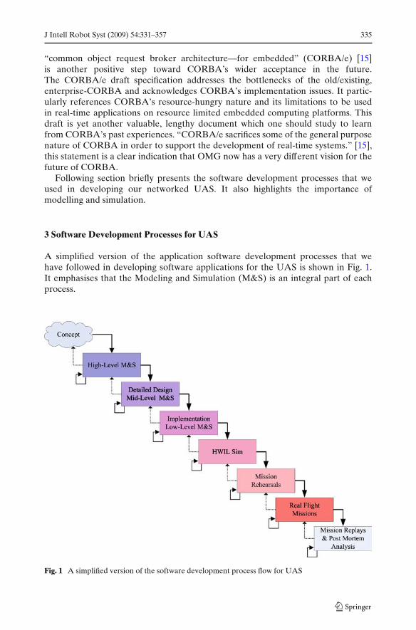
A simplified version of the application software development processes that wehave followed in developing software applications for the UAS is shown in Fig. 1.It emphasises that the Modeling and Simulation (M&S) is an integral part of eachprocess.
Fig. 1 A simplified version of the software development process flow for UAS
336 J Intell Robot Syst (2009) 54:331–357
Due to its cascading form, the development process model in Fig. 1 is known asthe waterfall model [16]. The waterfall model keeps iterations between neighbouringphases. In order to proceed from one phase to the next, often a review takes place todetermine if the phase is completed successfully. The large downward solid arrowsindicates the desired flow direction; from upper level phase to the lower level phase.However, sometime in practise, it become inevitable to go back to previous phases.This less desired upward flows are depicted by the dashed arrows. The small loop-back arrows on the lower left corner of the processes indicates that it is encouragedto iterate within the life-cycle phase before proceeding to the lower level phase.
The first stage in our software development process is the “high-level M&S” of theproposed system in Matlab/Simulink or similar high level simulation environments.After the validation1 of the new concepts, techniques and algorithms, the class hier-archies, hardware and software components are defined in the “detailed design, mid-level M&S” phase. At this phase, unified modeling language (UML) is particularlyuseful for software design and documentation as well as for defining the test cases.
The “Implementation, Low-Level M&S” phase consists of coding the actualrunning software (often in C/C++) and testing individual modules. In these tests low-level M&S, such as simulation of software modules, interaction between softwarecomponents, and sensor and control outputs are tested. Test results are used in theverification2 of the developed algorithms.
All software applications, their interaction with each other, and the actual hard-ware that will be used in the real flight missions are tested in the “hardware-in-the-loop simulation (HWIL Sim)” phase. The HWIL Sim test results are used for theverification and accreditation3 of the developed software, ie. results obtained atthe high-level simulation phase are compared with the HWIL Sim test results.
Following successful completion of the Validation, Verification and Accreditation(VV&A) procedures in the HWIL Sim are assumed to be ready for the “missionrehearsals” phase. At this stage, the operation plans are prepared. These plansstate the mission objective, define personnel work distribution and flight plans. Theoperational personnel are prepared for the mission through repeated missionrehearsals performed in the HWIL Sim environment.
After the operational personnel are reached to the required proficiency level forthe proposed missions, the “real flight missions” phase can be performed in theactual flight area. During real flight missions, a number of data logging processesare performed both onboard the UAVs and on the ground stations. The logged dataare used in “mission replays and post mortem analysis” phase. Soon after the flightoperations, the logged data are replayed in the RMUS environment and the missionteam assess if mission objectives are reached and decide if the flight mission needs tobe repeated or not. The logged data is later used in the RMUS environment manytimes for post-mortem analysis of the missions.
1In the context of modelling and simulation (M&S), validation is the process of determining whetherthe selected simulation model accurately represents the system.2Verification, answers the question of whether the selected simulation model is implementedcorrectly.3Accreditation is “the official certification that a model or simulation is acceptable for use for aspecific purpose” [17].
J Intell Robot Syst (2009) 54:331–357 337
4 Multi-UAV System Architecture
This section presents the architecture of the multi-UAV system which is developedand successfully used by the ACFR. It also introduces the terminology used in thispaper.
Traditional UAV applications involve relatively large UAVs with the capabilityof carrying multiple payload sensors in a single platform. Ever increasing availability,and accessibility of smaller UAVs to the research community encourage the devel-opment of multi-UAV applications, where the mission sensors would be distributedacross a number of UAVs [18].
This is a major undertaking; it shifts the focus from the platform-centric tonetwork-centric capabilities, and it requires the adoption of a network-centric op-erational philosophy; “The network-centric operational philosophy relies on thecapability of shared situation awareness, through fusion of information disseminatedfrom a wide range of networked sensors, and decentralized decision making tocontrol the platforms and the sensors to maximize the information gain towardachieving the mission goals” [19].
Compared to the rather confined problem domain of the platform-centriccapability, the network-centric capability has a much broader domain. In network-centric systems, the information dissemination often takes place across heteroge-nous, mobile information sources and information consumers. In such systems, it isnot uncommon to have range and the bandwidth limited communication links withsporadic dropouts. However, in platform-centric systems, where all nodes are carriedon the same platform, the information dissemination occurs on a much faster andmore reliable local network.
The Brumby Mk III UAV (shown below) is capable of demonstrating theplatform-centric system capabilities when a single-UAV is used in the flight mis-sions [20]. More importantly, the network-centric system capabilities are also suc-cessfully demonstrated in flight missions in which, multiple Brumby Mk III UAVsare used [18, 21–25].
Brumby Mk III UAV The Brumby Mk III (Fig. 2) UAVs are the main flightplatform used by the ACFR in multi-UAV experiments. They are delta wing UAVswith 2.9 m wing span, pusher type four blade propeller, and conventional tricycle un-dercarriage suitable for takeoff from and landing on short grass and asphalt surfaces.The Brumby Mk III UAVs are designed and manufactured at The University ofSydney as the third generation UAVs in the Brumby series. Their maximum take-offweight (MTOW) is approximately 45 kg. The replaceable nose cone of the BrumbyMk III UAVs is ideal for reconfiguration of the UAVs to carry different missionpayloads in a plug-and-play manner.
Due to their delta wing design and the 16 Hp engine, the Brumby Mk III UAVsare very agile platforms. They can travel around 100 Knots (183.5 km/h) and have rollrates of approximately 180◦/s. The agility of a UAV relates to the highly dynamicnature of the platform. Compared to slow, hovering vehicles like helicopters andblimps, highly dynamic, fixed wing UAVs pose additional challenges, especially incontrol and in communication. Although the software framework presented in thispaper can be applied to a wide variety of systems, this paper is focused particularlyon the multi-UAV systems of the agile, fixed wing UAVs.
338 J Intell Robot Syst (2009) 54:331–357
Fig. 2 The Brumby Mk III UAV as it takes off. It has delta wing with 2.9 m wing span, pusher typepropulsion, conventional tricycle undercarriage, and replaceable sensor nose cone
Avionics The Brumby Mk III UAVs are equipped with relatively complex avionics(Fig. 3). In a typical configuration, a single Brumby Mk III UAV carries six PC104+computers, all networked through an onboard local area network (LAN), a flight andmission sensors, a microcontroller based fight mode switch (FMS), an optional digitalsignal processing (DSP) board, a spread spectrum radio modem, a 802.11b wirelessEthernet, a data acquisition module and power subsystem with two separate busesto power flight critical and non-flight critical payloads. The FMS is one of the mostcritical units in the Brumby Mk III UAV avionics architecture. It consists of a spreadspectrum radio modem and an embedded microcontroller board. Depending on theflight mode activation strategies defined by the system engineering and the HWILsimulations, the embedded application software running on the microcontrollerdrives the servo actuators either based on the remote control commands receivedfrom the ground or commands received from the flight control computer (FCC).Thus, the FMS can switch the UAV operation mode between remotely pilotedvehicle (RPV) and autonomous flight modes.
The FCC is a PC104+ computer and runs the QNX Real-Time Operating System(RTOS). The Brumby Flight Control System (BFCS) is the main high level applica-tion running on the FCC. The multi-threaded BFCS application calculates the real-time navigation solution and also generates low level control signals. Through theCommLibX/ServiceX middleware, the BFCS provides real-time navigation data toother onboard computers.
The Mission Computer (MC) also runs the QNX RTOS. As illustrated in Fig. 3,the FCC, and MC is linked via the onboard Ethernet hub. The MC is equippedwith an 802.11b wireless Ethernet card. It provides air to air and air to/from groundcommunication links. Compared to the FMS’s radio modem, the 802.11b provides awider bandwidth. However, the 802.11b link has much shorter communication rangeand it is subject to frequent dropouts. Hence, flight critical data, such as RPV controlcommands are not transmitted via wireless Ethernet but via a radio modem.
J Intell Robot Syst (2009) 54:331–357 339
Fig. 3 A high level representation of the Brumby Mk III UAV avionics with the optional missionsensors
The mission sensor control computers run embedded Linux in soft-real-time whilethe decentralised data fusion (DDF) computers run QNX in hard real-time. Allinteract with each other via CommLibX/ServiceX middleware.
Unmanned Aerial System (UAS) With a number of interacting onboard subsystemsUAVs are considered complex systems. However, a UAV is only one component of alarger whole; known as an unmanned aerial system (UAS), Fig. 4. This larger whole iscomprised of the ground stations, communication, telemetry, control and navigationequipments, sensor payloads and all the other entities necessary to perform missionsinvolving UAVs.
340 J Intell Robot Syst (2009) 54:331–357
Fig. 4 Illustration of amulti-UAV system consistsof heterogeneous UAVscarrying mission sensorsand communicating with theground control station aswell as with each other
As illustrated in Fig. 3 and in Fig. 5, an operational multi-UAV system hasa number of computing and communication nodes. Each node concurrently runsmultiple processes with various levels of real-time requirements. In this context,the term real-time, refers to satisfaction of timeliness requirements of individualprocesses [26].
Fig. 5 An operational multi-UAV system consists of a number of computing and communicationnodes onboard the UAVs and the ground station
J Intell Robot Syst (2009) 54:331–357 341
Multi-UAV systems have a number of components both on the ground and inthe air. The communication links between these distributed components, particularlyair to air and air to/from ground links are often subject to intermittent dropouts.Therefore, in practical terms, the overall system can not be controlled efficiently bya centralized computer. The nature of multi-UAV systems dictates the adoption ofdecentralised system architectures in which no single node is central for the operationof the entire system.
At the ACFR, the multi-UAV systems are often used for the demonstrationof DDF [27], Simultaneous localisation and mapping (SLAM) [28] and variouscooperative control [29] techniques. The decentralised system architecture is alsoan algorithmic requirement of these research areas [18].
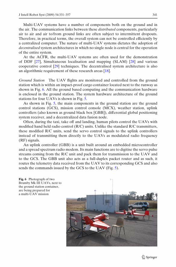
Ground Station The UAV flights are monitored and controlled from the groundstation which is within an impact-proof cargo container located next to the runway asshown in Fig. 6. All the ground based computing and the communication hardwareis enclosed in the ground station. The system hardware architecture of the groundstations for four UAVs is shown in Fig. 5.
As shown in Fig. 5, the main components in the ground station are the groundcontrol stations (GCS), mission control console (MCX), weather station, uplinkcontrollers (also known as ground black box [GBB]), differential global positioningsystem receiver, and a decentralized data fusion node.
Often, during the taxi, take off and landing, human pilots control the UAVs withmodified hand held radio control (R/C) units. Unlike the standard R/C transmitters,these modified R/C units, send the servo control signals to the uplink controllersinstead of transmitting them directly to the UAVs as modulated radio frequency(RF) signals.
An uplink controller (GBB) is a unit built around an embedded microcontrollerand a spread spectrum radio modem. Its main functions are to digitise the servo pulsestreams coming from the R/C unit and pack them for transmission to the UAV andto the GCS. The GBB unit also acts as a full-duplex packet router and as such, itroutes the telemetry data received from the UAV to its corresponding GCS and alsosends the commands issued by the GCS to the UAV (Fig. 5).
Fig. 6 Photograph of twoBrumby Mk III UAVs, next tothe ground station container,are being prepared fora multi-UAV mission
342 J Intell Robot Syst (2009) 54:331–357
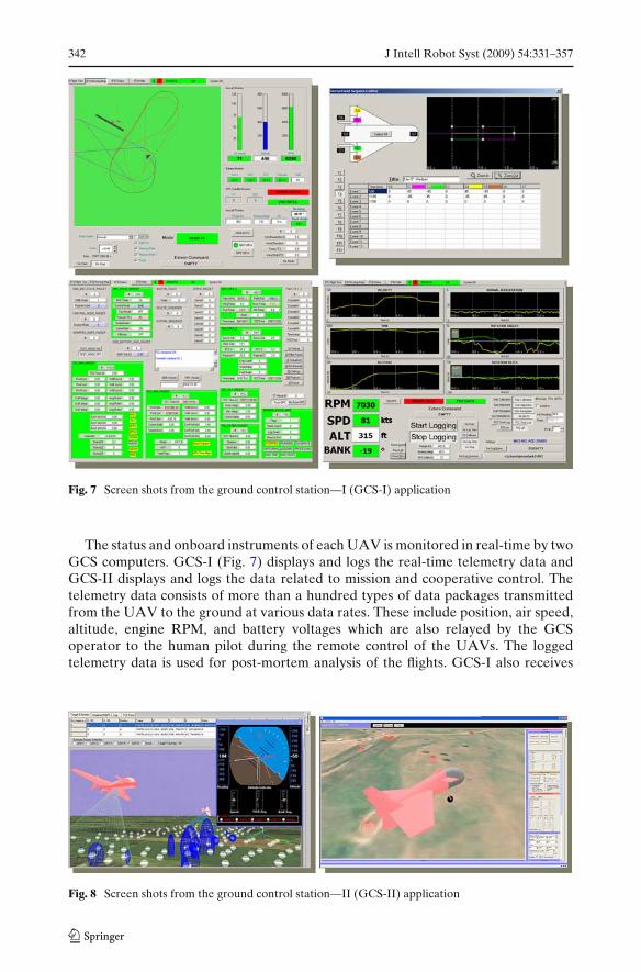
Fig. 7 Screen shots from the ground control station—I (GCS-I) application
The status and onboard instruments of each UAV is monitored in real-time by twoGCS computers. GCS-I (Fig. 7) displays and logs the real-time telemetry data andGCS-II displays and logs the data related to mission and cooperative control. Thetelemetry data consists of more than a hundred types of data packages transmittedfrom the UAV to the ground at various data rates. These include position, air speed,altitude, engine RPM, and battery voltages which are also relayed by the GCSoperator to the human pilot during the remote control of the UAVs. The loggedtelemetry data is used for post-mortem analysis of the flights. GCS-I also receives
Fig. 8 Screen shots from the ground control station—II (GCS-II) application
J Intell Robot Syst (2009) 54:331–357 343
the differential global positioning system (DGPS) messages and weather data viathe local network in the ground station. It relays the DGPS messages to the UAVvia the GBB. The local weather data is also displayed on GCS-I to aid in SituationAwareness (SA) [30] of the ground station operator and the pilot. As shown in Fig. 8,the GCS-II can optionally display, in real-time, the monitored UAV in a simulated3D environment. This helps GCS operators to increase their SA.
Both the GCS-I and the GCS-II are multi-threaded applications and written forthe MS-Windows operating system and they use CommLibX/ServiceX middleware.
5 A Framework for Distributed Autonomous Systems
The above mentioned multi-UAV system architecture exhibits the characteristicsof highly decentralised, distributed, and networked systems. This networked systemhas heterogenous nodes. The nodes have a number of different hardware. They runa variety of software applications on a number of different operating systems withdifferent levels of real-time requirements.
Typical multi-UAV missions, such as DDF, SLAM [18] and cooperative controldemonstration missions [31], performed by the ACFR consists of recurring devel-opment phases with similar or identical tasks like platform, and sensor modeling,communication, data logging and replay, visualisation and time synchronisation.In order to minimise the repeated solutions, a systematic approach for design,development, deployment, and maintenance of the UAS system software is needed.
Component based software frameworks provide a suitable domain to applysystematic approach to the software development phases. The “Lego character”of components offers well defined, simple, yet powerful integration mechanisms.This leads to easily re/configurable and maintainable systems. A Framework forDistributed Autonomous Systems (AFDAS) is designed and developed with thisvision in mind.
AFDAS aims to address both the low-level and high-level software requirementsof a networked UAS. These include distributed, real-time simulator architectures,the ground station, and the flight critical applications of multi-UAV systems. AFDASis leveraged by a large collection of software libraries, modules, and components thathave been developed over the years and still continue to expand with refinementof the existing code as well as the new software being developed for the new UASprojects.
AFDAS uses a top-down decomposition approach to the domain of networkedUAS and introduces a layered system software view. The operational and safetyrequirements of the networked UAS play an important role in these approaches. Thedomain partitioning, and framework layering increase the efficiency of managing thecomplex system requirements.
Control layers have different levels of task abstractions; higher control layers havemore abstract tasks than the lower layers. Abstraction is also reflected to the real-time requirements. The real-time requirements ease at higher level of abstractions.
The networked UAS software system is designed in a hierarchical form. As it isillustrated in Fig. 9 and tabulated in Table 1 the system software hierarchy can bespecified in four layers; actuator, subsystem, system, and system of systems (SoS)layers.
344 J Intell Robot Syst (2009) 54:331–357
Fig. 9 Layers of thenetworked UASsoftware hierarchy
Actuator Layer The actuator control layer provides access to the actuators viadriver electronics and low-level device driver software modules. It is common tocontrol the actuators by microcontroller based electronics boards. The small micro-controller boards often programmed with proprietary C compilers, and assemblers.
Table 1 Networked UAS Software Hierarchy
Control HW&SW SW Tools RTlayers modules requirements
SoS WAN & LAN, Matlab, Simulink, Non real-time,layer IPC, comms. Java, C/C++ soft real-time,
event based tasksSystem Computers, Matlab, Simulink, Hard real-time,
The device driver software modules for these boards are carefully written, optimisedcodes with hard real time requirements tailored for particular hardware.
Subsystem Layer The subsystem layer provides low-level control and fusion be-haviours. Low-level sensor data fusion, such as INS-GPS fusion for navigationsolutions, and low-level servo controls such as PID servo loops are typical tasks at thislevel. This layer is built around multiple embedded computers, or microcontrollerboards, connected to servo drivers and sensors.
The tasks at the subsystem layer are often programmed in C/C++ and run at aconstant rate in hard real-time. The concurrent tasks running on a single embed-ded computer or on multiple networked embedded computers use Inter-ProcessCommunication (IPC) mechanisms for data exchange.
System Layer The system layer provides high level control and decision makingfunctionalities. Some of the tasks at this layer are the system level diagnosticsand error handling, path planning, way-point navigation and guidance. These taskscould be periodic tasks or event based tasks with soft real-time or hard real-timerequirements. Although most of the software code for the system layer tasks arehand written in C/C++, other higher level languages and graphical tools like MatLaband Simulink can also be used to auto generate the C/C++ codes [29, 31, 32].
The system layer consists of heterogenous set of computers, networked togethervia wide area network (WAN) and/or local area network (LAN). The networkedcomputers in this layer also use various IPC and high level communication mecha-nisms for data exchange between multiple processes.
System of Systems Layer The System of Systems (SoS) layer is the highest levelof control in the control hierarchy. Compared to the lower layers, the real-timerequirements of this level are eased. The tasks at the SoS layer are concentratedon the interaction and interoperability of multiple systems. Humans may also be inthe control loop in the SoS layer.
Many UASs have inherently distributed system architectures. In order to achieveinteroperability at the SoS layer, the software associated with each individual systemshould meet a common set of requirements for their interfaces with each other.Often, multiple heterogeneous vehicles, which are complex systems themselves, andother systems, such as stationary sensors networks, operate together to fulfill themission objectives in a dynamic environment. Communication plays a major role intheir interactions since cooperation (often [33, 34]) requires communication betweenthe vehicles [35, 36].
Depending on the communication requirements, layers can be linked together byusing a number of different inter-process communication (IPC) methods, such asshared memory, message passing, pipes, sockets, and remote procedure calls (RPC)etc. or higher level middlewares. Middleware is a suite of software that provides theconnectivity between multiple otherwise isolated applications.
The difficulties of using different IPC mechanisms and middlewares should not beunderestimated. Different IPC techniques have strengths, weaknesses, and traps thatthe software developers should manage in order to facilitate reliable and effectivecommunication between tasks.
Mastering the intricacies of some of the traditional IPC techniques is a challengingtask that requires time and effort, and above all experience. Developers who have the
346 J Intell Robot Syst (2009) 54:331–357
expertise in control of autonomous systems may not necessarily have the sufficientlevel of expertise in IPC. The CommLibX/ServiceX middleware [37, 38] which isdetailed in the next section, addresses this problem and offers a simple, yet powerfulway of IPC for the UAS software developers.
6 CommLibX/ServiceX Middleware
Increasing complexity of autonomous systems and the adoption of network-centricoperational philosophy are motivating the development of large scale distributedsystems. The non-distributed/stand-alone system approach is becoming a thing ofthe past.
Distributed system software components are glued together with middleware.Middleware is the systems software connecting the distributed software compo-nents, applications, and simulation modules together. As illustrated in Fig. 10 themiddleware system often resides between the operating system and the high leveldistributed applications.
Middleware hides the complexities and the heterogeneities of the underlyingoperating systems, network protocols, and hardware of the target computers. Itenhances the efficiency and quality of the distributed system development work andsimplifies the maintainability.
There are many different middlewares available in the software market today.They can be grouped according to their application domains, language support,and real-time characteristics. Some of them are designed to have target specificrequirements of a particular application domain, such as distributed simulation [39],and the others are general purpose [40].
Fig. 10 CommLibX/ServiceX is the middleware, designed and developed to support the seamlessnetwork UAS research works at ACFR
J Intell Robot Syst (2009) 54:331–357 347
The CommLibX/ServiceX is a novel, layered software framework designed as amiddleware to provide hardware, operating system, and programming language ab-straction for the communication, and other system services required for a networkedUAS. The CommLibX/ServiceX middleware supports the seamless network UASresearch works at the ACFR.
Originally, the CommLibX/ServiceX middleware is designed in UAS applicationsin mind. However, it is used on a number of other autonomous systems, and dis-tributed simulation environments. The CommLibX/ServiceX middleware has veryflexible and modular architecture. Its base code is small in size, and through theplug-in modules, its functionality can be tailored for the specific application domain.The CommLibX/ServiceX middleware supported on QNX, Linux, and Windowsoperating systems. A cut-down version of the CommLibX/ServiceX middleware isalso demonstrated on low end small Atmel AVR microcontrollers with no operatingsystem.
One of the most important objectives of the CommLibX/ServiceX middlewarearchitecture is to enable the application developers to develop high-level distributedapplications, much the same way, as if they were developing stand-alone, non-distributed applications. This assists the developers in focussing on their applicationsrather than the elaborately complex details of the underlaying operating systems andhardware.
The CommLibX/ServiceX middleware consists of two major parts; the Comm-LibX library and the ServiceX module (Fig. 10). The CommLibX is the interfacebetween the high level distributed application and ServiceX. As its name impliesServiceX provides the middleware services including communication, task schedul-ing, and some limited direct hardware control. Each application initiates an instanceof the CommLibX. The high level applications invoke operations on ServiceX via theCommLibX instance. And similarly, the ServiceX invokes operations on the high-level application through the same instance of the CommLibX.
The separation of the middleware into two parts as CommLibX and ServiceX hasanother benefit; CommLibX “isolates” ServiceX from the high-level applications.Execution of ServiceX does not depend on the state of the user application. Whatthis means in practice is that an ill-behaved user application does not affect theperformance of ServiceX. Hence, a faulty program does not jeopardize the operationof the rest of the distributed system.
In a CommLibX/ServiceX based distributed system, high-level applications mayrun on either one or multiple computers. Often, high-level applications are notaware if the other applications are running on the same computer or not. Regardlessif they are running on the same computer or on separate computers, high-levelapplications do not directly interact with each other, but the interaction occursthrough virtual channels. The virtual channel is a novel concept introduced bythe CommLibX/ServiceX middleware. The virtual channels are the logical linksbetween communicating nodes. Often they are used for the logical separation ofdifferent kinds of data packages. The virtual channels can be allocated either a singlecommunication medium or they can be spread over all the communication mediumsavailable to the distributed system.
Figure 11 illustrates a simplified version of a high-level information disseminationmap of a networked UAS. Figure 4 and Fig. 5 would also help for the inter-pretation of the information dissemination process. The information flow between
348 J Intell Robot Syst (2009) 54:331–357
Fig. 11 Information dissemination map of a networked UAS with two UAVs
communicating entities are represented by the directed arrows. The line patterns ofthe arrow indicate the context of the information/data that will be communicatedbetween nodes via virtual channels.
Intentionally, Fig. 11 does not show the physical properties of communicationmedium or the absolute physical locations of the applications constituting thecommunicating nodes. The information dissemination map is what the applicationdevelopers need to know about the high level interactions between subsystems.Depending on the final physical configuration of the system, the virtual channels canbe allocated and reallocated on any physical medium (cable or wireless Ethernet,Controller Area Network (CAN), shared memory etc.) available to the system. Andthe high-level application developers do not need to have any assumption about thephysical nature of the communication channel. Furthermore, hardware configurationof the system can be changed, even at runtime, without changing the source code.
Virtual channels have event driven interfaces which ensures that upon receivinga data package/message from a virtual channel, the CommLibX invokes a user call-back function for data transfer.
As illustrated in Fig. 12, ServiceX provides middleware services and messagetransfer between CommLibX instances. ServiceX links the physical communicationlayers to the CommLibX library. ServiceX supports various networking devicesincluding the CAN, standard serial ports (RS232/RS422/RS485), cable and wirelessEthernet, shared memory etc. It also supports multiple protocols including UDP,TCP/IP, and additional communication hardware and protocols can be interfaced toServiceX through plug-in-modules.
For the applications running on the same computer, ServiceX maps virtualchannels to the shared memory for maximum throughput. Virtual channels can be
J Intell Robot Syst (2009) 54:331–357 349
Fig. 12 Virtual channels and message exchange in CommLibX/ServiceX middleware
allocated on the same or different communication devices for applications runningon separate networked computers.
The mapping of virtual channels to different physical mediums can be betterexplained by an example. Figure 12, shows two computers: “Computer-A”, and“Computer-B”. The first computer runs three high-level applications (A, B, C)and the other computer runs two high-level applications (D, E). Applications A,Band D communicate with each other over the virtual channel “VC-1”. Similarly,applications C and E communicate via virtual channel “VC-2”.
Computer-A, and Computer-B share two physical communication mediums; aCAN bus, and an Ethernet network. VC-1 is mapped to the Ethernet network whileVC-2 is mapped to the CAN bus. Since application A, and B are running on the samecomputer (Computer-A), and using the same virtual channel (VC-1), then, regardlessof the external communication mediums, the ServiceX links the application A and Bover the shared memory. However, as shown in Fig. 12, VC-1 is also mapped to theEthernet so that application D can also communicate with applications A and B.
Figure 13 shows ServiceX’s multi-layered, hierarchical architecture. The layeredarchitecture of ServiceX simplifies its port to different operating systems anddifferent hardware. It consists of following three layers;
OS and HW Adaptation Layer This is the lowest level and provides interfaces tothe operating system and to the hardware. A significant portion of this layer shouldbe re-written when ServiceX needs to be ported to a new operating system or to anew computing hardware.
350 J Intell Robot Syst (2009) 54:331–357
Fig. 13 ServiceX hasmulti-layered architecture,and allows its features to beextended through plug-inservices
Basic Services Layer The basic services layer resides on top of the adaptation layer.As its name implies, the basic services layer provides bare minimum services forCommLibX/ServiceX middleware. These include, creation and utilisation of virtualchannels, data logging, message packing/unpacking, basic communication statistics,support for basic communication hardware including Ethernet, CAN, standard serialports and shared memory.
Plug-in Services Layer The plug-in services layer resides on top of the basicservices layer. The features of ServiceX, hence the features of the overall Comm-LibX/ServiceX middleware, can be extended by incorporating plug-in services.
All the distributed software applications running on board the UAVs and onthe ground station use CommLibX/ServiceX middleware. We also used Comm-LibX/ServiceX in our real-time mission simulator, and HWIL simulator. The nextsection gives an overview of our distributed real-time simulator architecture.
7 Real-Time Multi-UAV Simulator
In UAV experiments there are many avenues of failure: in software, hardware, andconceptual understanding and failures in algorithm development are just a few of
J Intell Robot Syst (2009) 54:331–357 351
many probable failure points. These pose significant burdens on the progress of theproject as each flight test poses a risk to the survivability. Hence, any new hardwareor software module has to be thoroughly tested before used on real missions. A realtime multi-UAV simulator (RMUS) system has been developed, at the earlier phaseof ACFR’s UAV research programs to address the problems associated with real lifeexperiment [37].
The RMUS has been implemented as a testing and validation mechanism forour networked UAS. These mechanisms include off-line simulation of complexscenarios, HWIL tests, mission rehearsals, on-line mission control for real UASdemonstrations, and validation of real test results. Prior to real flight operations,all algorithms, software implementations, their interaction with each other, and theactual hardware that will be used in the flight missions should be extensively tested insimulation [41]. The software and hardware, once validated, are then ported directlyto the UAV platforms ready for real flight tests.
The RMUS has been extensively used in the various phases of the developmentof all single-UAV and multi-UAV flight operations conducted by the ACFR [18, 22,24, 27, 31, 32, 38, 42–45]. These real flight operations include the demonstrations ofvarious DDF, SLAM, and cooperative control techniques. The RMUS has been alsoused in a large number of other simulation-only UAV experiments [35, 46–48].
The RMUS architecture encompasses distinct architectural styles; it is distributed,it is multi-layered and it is event-based with message-passing foundations. TheRMUS’s architecture promotes component-based, modular, distributed simulationdevelopment where the simulation modules interact with each other with messagepassing mechanisms provided by the CommLibX/ServiceX middleware.
The key terminology and concepts comprising the RMUS architecture are asfollows;
Simulator Cluster A simulator cluster is a group of distributed simulation modules,and other hardware or software resources connected together that act as a singlesystem to provide a wide span of resources and high processing power for complexsimulations. The size and content of the cluster can be changed as the simulationrequirements may vary.
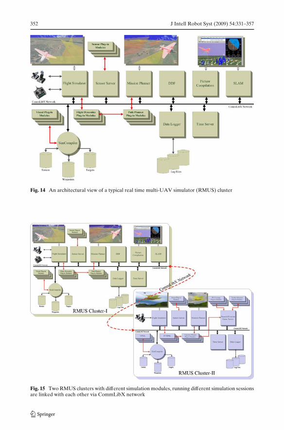
Figure 14 illustrates a typical architecture of a RMUS cluster. More than onesimulator cluster can be linked with each other via CommLibX/ServiceX middle-ware. Figure 15 illustrates two linked RMUS clusters. If a RMUS cluster should beinterfaced with another simulation environment with a different protocol standard, itmay require a “bridge” application on each ends of the clusters to convert from oneprotocol standard to the other.
Simulation Modules Simulation modules are composed of either software applica-tions or physical devices comprising the simulation cluster. A simulation module maybe an implementation of an algorithm such as the generation of Voronoi diagrams,the DDF algorithm, SLAM code, or a flight control code, or a physical device such asGPS, R/C unit, radar electronics etc. interfaced to the simulation cluster. In Fig. 14and in Fig. 15, major simulation modules are represented as square shaped blocks.The functionality of simulation modules can be enhanced through Plug-in-Modules.The rectangle blocks in Fig. 14 and in Fig. 15 show the plug-in-modules. The plug-in-modules are often created as dynamic libraries.
352 J Intell Robot Syst (2009) 54:331–357
Fig. 14 An architectural view of a typical real time multi-UAV simulator (RMUS) cluster
Fig. 15 Two RMUS clusters with different simulation modules, running different simulation sessionsare linked with each other via CommLibX network
J Intell Robot Syst (2009) 54:331–357 353
Simulation Objects Simulation objects are instances of simulation entities. Thesimulation objects interact with each other as well as interact with the physicaldevices, via message passing mechanism. Simulation objects may have 3D graphicappearances, or they may be non-visual. For example, in a RMUS simulationsession, a simulated radar (a non-visual simulation-object) carried on a simulatedUAV (visual simulation-object) may detect a simulated land vehicle (another visualsimulation-object) on a terrain (yet another visual simulation-object) as a Feature ofInterest (FoI). The 3D appearance of the simulation objects are defined by Visual-Plug-in-Modules (VPMs).
Simulation objects may be associated with pre-defined behaviors or their behaviorcan be (re)defined either through plug-in-modules or through the interaction withthe other simulation objects. Consider a simple scenario; a UAV of a particular typemay have a predefined flight dynamics model, and its flight can be simulated by usingthis model. The same UAV simulation object may receive a “kill the engine”, and a“deploy parachute” pseudo commands from the GCS object. In such circumstances,the UAV object may load separate plug-in modules defining the flight dynamics ofthe deployed parachute. During the rest of the simulation, the flight path of the UAVcan be calculated based on the flight dynamics model of the parachute rather than theflight dynamics model of the UAV.
Simulation Session Simulation session is the participation of simulation modulesand execution of the simulation to achieve the aimed simulation tasks. Dependingon the complexity and processing power requirements of the simulation, simulationsessions can be initiated on a single computer or on multiple networked computers.
Simulation session may be of the type HWIL, “human-in-the-loop” (HIL), ormission rehearsals etc. The physical devices are directly utilized in HWIL simulationsessions. Direct human interaction with the simulation is also possible. A typicalexample of HWIL and HIL simulation session would involve a human pilot usinga real R/C unit to fly a simulated UAV object over a simulated terrain to captureaerial images of the FoIs.
The HWIL simulation environment used at the ACFR is constructed around theRMUS. Hence, both the single-UAV, and multi-UAV missions can be simulated inreal-time.
Figure 16 shows the HWIL Sim system configuration for two Brumby Mk IIIUAVs. In order to reflect the real operational system configuration at a maximumlevel, the distributed HWIL Sim system is configured in such a way that it has almostidentical architecture with the system hardware used for the real flight missions.By comparing Figure 16 with Figure 5 one can see the similarities and differencesbetween the HWIL Sim architecture and the architecture of the ground station usedin real flight trials. (The former figure shows a HWIL Sim for two UAVs and thelatter figure shows the system architecture for four UAVs, hence comparison shouldbe made by per-UAV basis.)
During the HWIL simulations, the real UAVs remain stationary. Therefore, theflight sensors can not produce flight data. The “HWIL-I” and “HWIL-II” computersconcurrently run flight vehicle dynamics models to simulate the UAV motions. Thesensor data (GPS, IMU, air data, RPM etc.) are generated in real-time based on thesemodels. Synchronous operation capability is often required for the HWIL computers.The system wide synchronousity is achieved through the Time Management Services(TMS) of the CommLibX/ServiceX middleware.
The software applications for the HWIL simulation environment has been de-veloped based on AFDAS design drivers. Therefore, the HWIL Sim environmentaccommodates software applications running on multiple operating systems (QNX,Linux, and Windows) developed in multiple programming languages (MatLab,C/C++, and Delphi) and provide support for a number of communication hardwareand software mediums (RS232, RS422, CAN, cable and wireless Ethernet, spreadspectrum radio modem).
Figure 17 is the photograph of the HWIL Sim set-up for two Brumby Mk IIIUAVs. Note that the wings, the propeller, and the nose cone covers are removedfrom the UAVs and they are elevated on the custom made stands for the easy accessto internals. The cables connected to the UAVs are providing the electrical power tothe payload electronics, network connection, and flight sensor connections.
Fig. 17 The HWIL simulationset-up for two BrumbyMk III UAVs
J Intell Robot Syst (2009) 54:331–357 355
8 Conclusion and Future Works
Due to the advancements in electronics, sensor, and communication technologiesand evolutions in material science, and manufacturing technologies, UAVs arebecoming more accessible by academic R&D institutions. The UAS developers caneasily acquire highly standardised COTS modular hardware components from vari-ous suppliers. However, it is difficult to find well established standardised softwarecomponents particularly for widely distributed, networked UASs.
This paper presented a software development methodology for a networked UAS.The methodology is strongly based on the use of real-time multi-UAV simulator(RMUS), distributed HWIL simulator, and CommLibX/ServiceX middleware. TheHWIL simulator and the RMUS have been demonstrated on a large number of pre-mission planning tests as well as on the post mortem analysis of the flight missions byreplaying the logged mission data, and comparing it with the simulation results forthe re-evaluation of the system models.
The CommLibX/ServiceX is a novel middleware which provides hardware, oper-ating system, and programming language abstraction for the communication, andother system services required for a networked UAS. The CommLibX/ServiceXmiddleware enables the application developers to develop high-level distributedapplications, much the same way, as if they were developing stand-alone, non-distributed applications. Hence, the developers can focus on their applications ratherthan the low-level details of the underlaying operating systems and hardware.
All these software are based on A framework for distributed autonomous sys-tems (AFDAS). AFDAS uses domain decomposition approach to the domain ofnetworked UAS and introduce a layered system software view. It examines theUAS software applications in four layers; actuator, subsystem, system, and Systemof Systems (SoS) layers.
The presented software development methodology successfully has been used formany years on widely distributed, network UAS, consisting of multiple Brumby MkIII UAVs, a comprehensive ground station, containing network of computers. TheBrumby Mk III UAV avionics is also comprised of a network of computers, sensors,and communication subsystems.
Both the RMUS and the CommLibX/ServiceX middleware are open to expan-sion. Development of additional new simulation modules for the RMUS is an ongo-ing process as more researchers use the RMUS in their research. Current activitiesinclude the building hovering UAVs (HUAVs) to our existing multi-UAV system tobuild widely distributed, and decentralised, networked UAS with heterogenousUAVs.
References
1. NATO, STANAG 4586 (Standard Interfaces of UAV Control System (UCS) for NATO UAVInteroperability), NATO Standardization Agency (NSA) (2004)
2. Ernst, D., Valavanis, K., Garcia, R., Craighead, J.: Unmanned vehicle controller design, eval-uation and implementation: from MATLAB to printed circuit board. J. Intell. Robot. Syst. 49,85–108 (2007)
3. Song, S.J., Liu, H.: Hardware-in-the-loop simulation framework design for a UAV embeddedcontrol system. In: Control Conference CCC 2006, pp. 1890–1894 (2006)
356 J Intell Robot Syst (2009) 54:331–357
4. Gösta, P.D., Kuchcinski, G.K., Sandewall, E., Nordberg, K., Skarman, E., Wiklund, J.: TheWITAS unmanned aerial vehicle project. In: ECAI 2000. Proceedings of the 14th EuropeanConference on Artificial Intelligence, pp. 747–755. Berlin (2000)
5. Henning, M.: The rise and fall of CORBA. ACM Queue 4, 28–34 (2006)6. Maffeis, S., Schmidt, D.C.: Constructing reliable distributed communication systems with
CORBA. Commun. Mag., IEEE 35, 56–60 (1997)7. Henning, M., Vinoski, S.: Advanced CORBA programming with C++: Addison-Wesley (1999)8. Brooks, A., Kaupp, T., Makarenko, A., Williams, S., Orebaeck, A.: Orca: a component model
and repository. In: Brugali, D. (ed.) Software Engineering for Experimental Robotics, vol. 30 ofSTAR, pp. 231–251. Springer (2007)
9. Corke, P., Sikka, P., Roberts, J., Duff, E.: DDX: a distributed software architecture for roboticsystems. In: Australasian Conference on Robotics and Automation. Canberra Australia (2004)
10. Paunicka, J.L., Corman, D.E., Mendel, B.R.: A CORBA-based middleware solution for UAVs.In: Fourth IEEE International Symposium on Object-oriented Real-time Distributed Comput-ing, ISORC-2001, pp. 261–267. Magdeburg Germany (2001)
11. Jangy, J.S., Tomlinz, C.J.: Design and implementation of a low cost, hierarchical and modularavionics architecture for the DragonFly UAVs. In: Proceedings of the AIAA Guidance, Naviga-tion, and Control Conference. Monterey (2002)
12. Wills, L., Kannan, S., Heck, B., Vachtsevanos, G., Restrepo, C., Sander, S., Schrage, D., Prasad,J.V.R.: An open software infrastructure for reconfigurable control systems. In: Proceedings ofthe American Control Conference, pp. 2799–2803 (2000)
13. Kuo, Y.-h., MacDonald, B.A.: Designing a distributed real-time software framework for robotics.In: Australasian Conference on Robotics and Automation (ACRA). Canberra (2004)
14. Croak, T.J.: Factors to consider when selecting CORBA implementations, CrossTalk. J. Def.Softw. Eng. 14, 17–21 (2001)
16. Boehm, B.W.: Seven basic principles of software engineering. J. Syst. Software 3, 3–24 (1983)17. Department of Defense, D.5000.61, DoD modeling and simulation verification, validation, and
accreditation. http://www.cotf.navy.mil/files/ms/DoDI500061{_}29Apr96.pdf (2003)18. Sukkarieh, S., Nettleton, E., Kim, J.-H., Ridley, M., Göktogan, A.H., Durrant-Whyte, H.:
The ANSER Project: data fusion across multiple uninhabited air vehicles. Internat. J. Robot.Research 22, 505–539 (2003)
19. Göktogan, A.H.: A software framework for seamless R&D of a networked UAS. In: PhDThesis, Australian Centre for Field Robotics, School of Aerospace, Mechanical and MechatronicEngineering Sydney. The University of Sydney (2007)
20. Kim, J., Sukkarieh, S.: Autonomous airborne navigation in unknown terrain environments. IEEETrans. Aeros. Electron. Syst. 40, 1031–1045 (2004)
21. Nettleton, E.: ANSER past and present—multi UAV experimental research. In: The IEE Forumon Autonomous Systems, (Ref. No. 2005/11271), p. 9 (2005)
22. Nettleton, E., Ridley, M., Sukkarieh, S., Göktogan, A.H., Durrant-Whyte, H.: Implementationof a decentralised sensing network aboard multiple UAVs. Telecommun. Syst. 26(2–4), 253–284(2004)
23. Ridley, M., Nettleton, E., Göktogan, A.H., Brooker, G., Sukkarieh, S., Durrant-Whyte, H.F.:Decentralised ground target tracking with heterogeneous sensing nodes on multiple UAVs. In:The 2nd International Workshop on Information Processing in Sensor Networks (IPSN’03),pp. 545–565. Palo Alto, California, USA (2003)
24. Sukkarieh, S., Göktogan, A.H., Kim, J.-H., Nettleton, E., Randle, J., Ridley, M., Wishart, S.,Durrant-Whyte, H.: Cooperative data fusion and control amongst multiple uninhabited air vehi-cles. In: ISER’02, 8th International Symposium on Experimental Robotics. Sant’Angelo d’Ischia,Italy (2002)
25. Bryson, M., Sukkarieh, S.: Toward the real-time implementation of inertial SLAM using bearing-only observations. In: Journal of Field Robotics (2006)
26. Buttazzo, G.C.: Hard real-time computing systems: predictable scheduling algorithms andapplications. In: 2nd ed. p. 425. New York, Springer (2005)
27. Nettleton, E.: Decentralised architectures for tracking and navigation with multiple flight ve-hicles. In: PhD Thesis, Department of Aerospace, Mechanical and Mechatronic EngineeringSydney. The University of Sydney (2003)
28. Kim, J.-H.: Autonomous navigation for airborne applications. PhD Thesis, Australian Centrefor Field Robotics, School of Aerospace, Mechanical and Mechatronic Engineering Sydney. TheUniversity of Sydney, p. 237 (2004)
29. Cole, D.T., Göktogan, A.H., Sukkarieh, S.: The implementation of a cooperative control archi-tecture for UAV teams. In: 10th International Symposium on Experimental Robotics (ISER’06).Rio de Janeiro, Brazil (2006)
30. Endsley, M.R., Garland, D.J.: Theoretical underpinning of situation awareness: a critical review.In: NJ, M., Erlbaum, L. (eds.) Situation Awareness Analysis and Measurement: Analysis andMeasurement, pp. 3–33 (2000)
31. Cole, D.T., Sukkarieh, S., Göktogan, A.H.: System development and demonstration of a UAVcontrol architecture for information gathering missions. J. Field Robot. 23, 417–440 (2006)
32. Cole, D.T., Sukkarieh, S., Göktogan, A.H., Hardwick-Jones, R.: The development of a real-timemodular architecture for the control of UAV teams. In: Field and Service Robotics, FSR’05,pp. 321–332. Port Douglas, Australia (2005)
33. Michael, R.G., Matthew, L.G., Jeffrey, S.R.: Cooperation without communication. In: Distrib-uted Artificial Intelligence, Morgan Kaufmann Publishers Inc., pp. 220–226 (1988)
34. Otanez, P.G., Campbell, M.E.: Hybrid cooperative reconnaissance without communication. In:44th IEEE Conference on Decision and Control’05 and European Control Conference’05.CDC-ECC ’05, pp. 3541–3546 (2005)
35. Chung, C.F., Göktogan, A.H., Cheang, K., Furukawa, T.: Distributed simulation of forwardreachable set-based control for multiple pursuer UAVs. In: SimTecT 2006 Conference Proceed-ings, pp. 171–177. Melbourne, Australia (2006)
36. Speranzon, A., Johansson, K.H.: On some communication schemes for distributed pursuit-evasion games. In: Proceedings of 42nd IEEE Conference on Decision and Control, pp. 1023–1028 (2003)
37. Göktogan, A.H., Nettleton, E., Ridley, M., Sukkarieh, S.: Real time Multi-UAV simulator. In:IEEE International Conference on Robotics and Automation (ICRA’03), pp. 2720–2726. Taipei,Taiwan (2003)
38. Göktogan, A.H., Sukkarieh, S., Isıkyıldız, G., Nettleton, E., Ridley, M., Kim, J.-H., Randle, J.,Wishart, S.: The real-time development and deployment of a cooperative multi-UAV system. In:ISCIS03 XVIII - Eighteenth International Symposium on Computer and Information Sciences,Antalya—Türkiye, pp. 576–583 (2003)
39. DMSO: High level architecture for simulation interface specification, defence modelling andsimulation office (DMSO). https://www.dmso.mil/public/ (1996)
40. O.M.G. (OMG): CORBA: Common Object Request Broker Architecture. http://www.corba.org41. Göktogan, A.H., Sukkarieh, S.: Simulation of multi-UAV missions in a real-time distributed
hardware-in-the-loop simulator. In: Proceeding of the 4th International Symposium on Mecha-tronics and its Applications (ISMA07). Sharjah, UAE (2007)
42. Göktogan, A.H., Brooker, G., Sukkarieh, S.: A compact millimeter wave radar sensor forunmanned air vehicles. In: Preprints of the 4th International Conference on Field and ServiceRobotics, pp. 101–106. Lake Yamanaka, Yamanashi, Japan (2003)
43. Nettleton, E.W., Durrant-Whyte, H.F., Gibbens, P.W., Göktogan, A.H.: Multiple platform local-isation and map building. In: Sensor Fusion and Decentralised Control in Robotic Stystems III,pp. 337–347. Boston, USA (2000)
44. Sukkarieh, S., Yelland, B., Durrant-Whyte, H., Belton, B., Dawkins, R., Riseborough, P., Stuart,O., Sutcliffe, J., Vethecan, J., Wishart, S., Gibbens, P., Göktogan, A.H., Grocholsky, B., Koch, R.,Nettleton, E., Randle, J., Willis, K., Wong, E.: Decentralised data fusion using multiple UAVs -The ANSER Project. In: FSR 2001, 3rd International Conference on Field and Service Robotics,Finland, pp. 193–200 (2001)
45. Göktogan, A.H., Sukkarieh, S.: Role of modelling and simulation in complex UAV R&Dprojects. In: 1st National Defense Applications, Modeling and Simulation Conference,(USMOS’05), pp. 157–166. Ankara-Türkiye (2005)
46. Göktogan, A.H., Sukkarieh, S., Cole, D.T., Thompson, P.: Airborne vision sensor detectionperformance simulation. In: The Interservice/Industry Training, Simulation and EducationConference (I/ITSEC’05), pp. 1682–1687. Orlando, FL, USA (2005)
47. Bourgault, F., Göktogann, A.H., Furukawa, T., Durrant-Whyte, H.: Coordinated search for alost target in a Bayesian world. In: Advanced Robotics, Special Issue on Selected Papers fromIROS 2003, vol. 18, pp. 979–1000 (2004)
48. Furukawa, T., Bourgault, F., Durrant-Whyte, H.F., Dissanayake, G.: Dynamic allocation andcontrol of coordinated UAVs to engage multiple targets in a time-optimal manner. In: IEEEInternational Conference Proceedings on Robotics and Automation, pp. 2353–2358 (2004)