15
PACS FPU PACS IHDR 12/13 Nov 2003 Distribution Boards and FPU Harness Concept R. Graue, D. Kampf Kayser-Threde
| Date post: | 30-Dec-2015 |
| Category: |
Documents |
| Upload: | iphigenie-kadin |
| View: | 28 times |
| Download: | 0 times |

PACS FPU
PACS IHDR 12/13 Nov 2003
Distribution Boards and FPU Harness Concept
R. Graue, D. KampfKayser-Threde

PACS FPU
PACS IHDR 12/13 Nov 2003
Sä
mtlic
he
Urh
eb
erre
ch
tlich
e-in
sb
es
on
de
re g
em
.Pa
r.2 A
bs
.1U
rh.G
sin
dv
orb
eh
alte
nV
erv
ielfä
ltigu
ng
, Ve
rbre
itun
g, A
us
ste
llun
g, V
orfü
hru
ng
,B
ea
rbe
itun
g, u
mg
es
ttaltu
ng
, so
ns
tige
Wie
de
rga
be
so
wie
Be
nu
tzu
ng
be
dü
rfen
de
r au
sd
rüc
klic
he
n s
ch
riftlich
en
Ein
ze
lge
ne
hm
igu
ng
de
r
Blue Detector Interface
Material
CAD Drawing No manual Changes
FPFPU
of
SheetDINWeightScaleSurfaceGen. tolerances
NameDateChangeState
File
Checked
Prep.
NameDate
1:2 -- A3 1
2
Assembly01 First Issue 22.03.01KC
--
02 9 connectors ->724.08.01KC
03 10mm <->15mm09.10.01KC
PACS-KT-ICD-0800W1.04
0800w104.CatDrawing
KC23.01.0204 Routing & Struts
60
92
,1
Bending begins at z(detector)= -105
First support after 90° with R=20mm
Distribution boardw
ith ra
diu
s c
en
ter a
t o
ptic
al p
up
il
4K level
2Klevel
Distribution Board – Blue Detector
PACS FPU
PACS IHDR 12/13 Nov 2003
Sä
mtlic
he
Urh
eb
erre
ch
tlich
e-in
sb
es
on
de
re g
em
.Pa
r.2 A
bs
.1U
rh.G
sin
d
vo
rbe
ha
lten
Ve
rvie
lfältig
un
g, V
erb
reitu
ng
, Au
ss
tellu
ng
, Vo
rfüh
run
g,
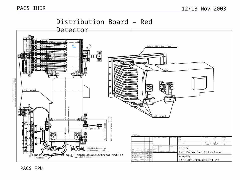
Red Detector Interface
Material
CAD Drawing No manual Changes
FPFPU
of
SheetDINWeightScaleSurfaceGen. tolerances
NameDateChangeState
File
Checked
Prep.
NameDate
1:2 -- A3 1
2
Assembly01 First Issue 10.04.00KC
--
02 09->08/09 12.03.00KC
22.03.002K Srap03 KC04 COG / Handling P.0705.01KC
KC23.07.01chamfer 10x1005
06 9 connectors->724.08.01KC07 routing & susp.23.01.02KC0900w107.CatDrawing
PACS-KT-ICD-0900W1.07
2K Level
60 (4k level)
92
,1(4
K l
eve
l)
First support after 90° with R=20mm
with
rad
ius a
t op
tica
l
pu
pil
Harnes
Bending begins atz(detector)=-105
4K Level
Distribution Board
Harness layout due to equal length of all detector modules
Distribution Board – Red Detector

PACS FPU
PACS IHDR 12/13 Nov 2003
EM Breadboard

PACS FPU
PACS IHDR 12/13 Nov 2003
• Rigid-flex boards• Material
– PCB: FR4– Flexible Harness: Polyimide
• Layout shall be designed according to CNES QFT/SP.0019
• Connectors: Cannon MDM 3401029 01B .... FR139• Capacitors: WIMA MKS 6,8 micro Farad, 50 VDC,
30 VAC• Resistors: RNC 55 according to ESA SCC 40001
001
Distribution Board – Approved Design

PACS FPU
PACS IHDR 12/13 Nov 2003
Distribution board test matrix
PC BDesign
MPE C ircu it D esign
KTLayout/M echanica l
D esign
Clearanceby M PE: Layout design,N et lis tby KT: M echanica l design
CQM / PFMSD "blue, red"ESA qualifiedInd. standard
Test bordsfor ESA pcbevaluation
PCB m anufacturing
-Circuit test-Optical inspection
PCBsCQM/PFM
componentsmounting
PCBIncoming inspection
Componentsprocurement and
qualificationby M PE/ESA
10x LN2Cryo cycles
-Circuit test-Optical inspection
Integration in FPFPU
PACS FPU
PACS IHDR 12/13 Nov 2003
Incoming inspection according to inhouse procedures
Visual inspection (components, bonding points) Measuring machine
Pin to pin continuity Insulation Cross talk ohmic resistance test
PCB layout test against Gerber data (automated inspection protocol)
Distribution Boards – Functional Verification Plan

PACS FPU
PACS IHDR 12/13 Nov 2003
Distribution Boards Functional Check Out Test Plan on FPU
level
• Functional tests (prior and after cold vibration tests and during He temperature tests)– Complete detector chain operation required– Detection of Photoconductor signals (tbd by MPE)– Test operations controlled by COE (MPE-tbc)– Validation of signals by MPE (determination of
nominal Photoconductor operation)
PACS FPU
PACS IHDR 12/13 Nov 2003
• PCB design completed• Manufacturing data package completed• ICD updated• CQM components tested /screened/released by
ESA (Resistors, capacitors, connectors)
CQM Distribution Board –Status - Completed Tasks I
Design, Documentation and Components
PACS FPU
PACS IHDR 12/13 Nov 2003
• EM Test board – Manufactured – Functional testing– Cryogenic cycling test (LN2)– Cryogenic vibration test (LHe) – Cryo STM test
• CQM Boards– PCBs Manufactured and under inspection (NCR wrt
anomalies)
• PFM Boards– PCBs Manufactured and under inspection (see CQM)
CQM Distribution Board –Status - Completed Tasks I
Assembly

PACS FPU
PACS IHDR 12/13 Nov 2003
• CQM Boards– Assembly– Functional testing– Cryogenic cycling test (LN2)– Qualification testing of bookbinder fabrication technology– Documentation (Inputs for DP)– Distribution board delivery until 11.2003
• PFM Boards– Asssembly and testing– Capacitor screening and distribution board delivery until
7.2004
Distribution Board –Status – Open Work and Schedule

PACS FPU
PACS IHDR 12/13 Nov 2003Distribution Boards Cryo Qualification Test
Matrix
Tests Planned Qualification
Tests
Performed BB Test
Performed Cryo STM
Test
Comments
Ambient simplified Functional Test prior / after Cold Vibration Test
X X - KT provided stand alone test
Cold Vibration Test (LN2 or He) – (3
axes)
X - X (He) MPE tests; mounted in Cryo STM (FPU)
Thermal Cycling LN2 X X - KT shock tests with 10 cycles
Ambient functional tests after thermal cycling test (LN2)
X X - KT tests
Thermal Vacuum Test (He) X X X MPE provided functional BB and CQM FPU tests
Functional Test at cryogenic temperatures (He)
X X - BB test provided by MPE with performance characterization
Distribution Boards are Cryo Vibration Qualified

PACS FPU
PACS IHDR 12/13 Nov 2003
• PFM Capacitor screening (Updated procedure) • Verification test plan of PCB bookbinder
technology manufacturing procedure in progress– Microscopic tests (e.g. cracks)– Thermal tests– Functional tests
Distribution Board - Open Points
PACS FPU
PACS IHDR 12/13 Nov 2003
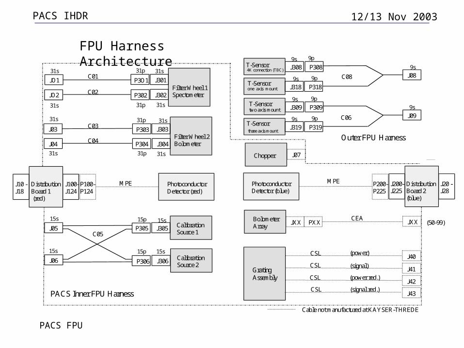
Filter Wheel 1SpectometerJ302P302JO2
J301P3O1JO1
Filter Wheel 2Bolometer
J303
J304
P303
P304
J03
J04
Calibration Source 2
J306P306J06
C01
C02
C03
C04
Calibration Source 1
J305P305J05C05
C06
Chopper J07
J308T-Sensor 4K connection (TBC)
T-Sensorone axis mount
P308
J318 P318
J08C08
Cable not manufactured at KAYSER-THREDE
PACS Inner FPU Harness
PhotoconductorDetector (red)
DistributionBoard 1 (red)
J100-J124
J10 -J18
P100-P124
MPE Distribution Board 2(blue)
J200-J225
P200-P225
PhotoconductorDetector (blue)
J20 -J28
MPE
GratingAssembly
J40
CSL
Bolometer Array
JXX PXX JXXCEA
(50-99)
J41
CSL
J42
J43
CSL
CSL
(power)
(power red.)
(signal)
(signal red.)
Outer FPU Harness
J309T-Sensortwo axis mount
T-Sensor three axis mount
P309
J319 P319
J09
31s
31s
31s
31s
31s
31s
31s
31s
31p
31p
31p
31p
9p
9p
9p
9p
9s
9s
9s
9s
9s
9s
15p
15p15s
15s
15s
15s
FPU Harness Architecture

PACS FPU
PACS IHDR 12/13 Nov 2003
• Harness designed and approved• Manufacturing data package released• CQM/PFM Manufacturing completed• CQM/PFM Hardware delivered and inspected• ICD approved• CQM harness under integration into FPU (CQM)
Harness – CQM/PFM Procurement Status


