CEMP-R Design Guide 1110-1-1 Department of the Army U.S. Army Corps of Engineers Washington, DC 20314-1000 DG 1110-1-1 12 November 1999 Engineering and Design DESIGN GUIDANCE FOR GROUND WATER/FUEL EXTRACTION AND GROUND WATER INJECTION SYSTEMS Distribution Restriction Statement Approved for public release; distribution is unlimited.
Transcript
CEMP-R
Design Guide1110-1-1
Department of the ArmyU.S. Army Corps of Engineers
Washington, DC 20314-1000
DG 1110-1-1
12 November 1999
Engineering and Design
DESIGN GUIDANCE FOR GROUNDWATER/FUEL EXTRACTION AND GROUND
WATER INJECTION SYSTEMS
Distribution Restriction StatementApproved for public release;
distribution is unlimited.
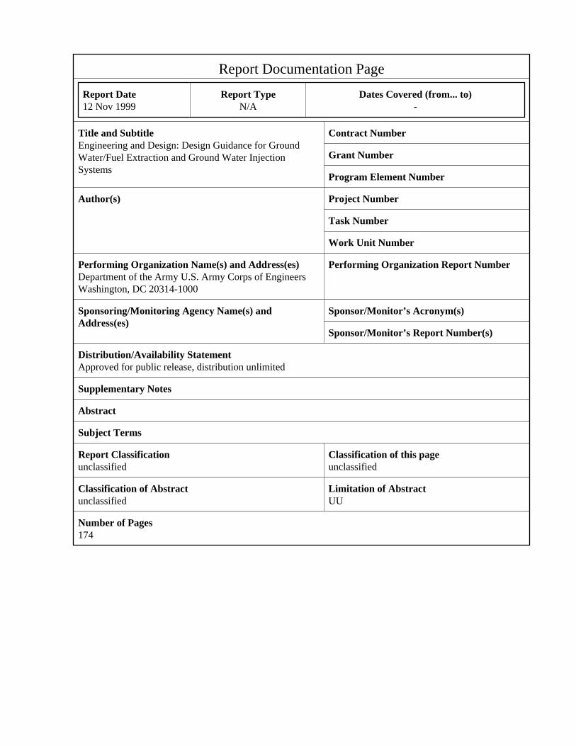
Report Documentation Page
Report Date 12 Nov 1999
Report Type N/A
Dates Covered (from... to) -
Title and Subtitle Engineering and Design: Design Guidance for GroundWater/Fuel Extraction and Ground Water Injection Systems
Contract Number
Grant Number
Program Element Number
Author(s) Project Number
Task Number
Work Unit Number
Performing Organization Name(s) and Address(es) Department of the Army U.S. Army Corps of EngineersWashington, DC 20314-1000
Performing Organization Report Number
Sponsoring/Monitoring Agency Name(s) and Address(es)
Sponsor/Monitor’s Acronym(s)
Sponsor/Monitor’s Report Number(s)
Distribution/Availability Statement Approved for public release, distribution unlimited
Supplementary Notes
Abstract
Subject Terms
Report Classification unclassified
Classification of this page unclassified
Classification of Abstract unclassified
Limitation of Abstract UU
Number of Pages 174
DG 1110-1-112 Nov 99
A-1
APPENDIX A
REFERENCES
A-1. Required Publications
a. U.S. Army Corps of Engineers (USACE)
CEGS 1351. Safety, Health and Emergency Response.
EM 1110-1-4005. Engineering and Design-In-situ Air Sparging.
EM 200-1-2. Technical Project Planning (TPP) Process.
EM 200-1-3. Requirements for the Preparation of Sampling andAnalysis Plans Ch. 1.
EM 1110-1-502. Technical Guidelines for Hazardous and ToxicWaste Treatment and Cleanup Activities.
EM 1110-1-4000. Monitoring Well Design, Installation, andDocumentation at Hazardous and/or Toxic Waste Sites, Eng.5056A-R.
EP 415-1-261. QA Representative's Guide, Vol.5.
ER 385-1-92. Safety and Occupational Health DocumentRequirements for Hazardous, Toxic and Radioactive Waste(HTRW)and Ordinance & Explosive Waste (OEW) Activities.
ER 1110-345-700. Design Analysis, Drawings andSpecifications.
ER 1110-1-263. Chemical Data Quality Management for HTRWActivities.
ER 1110-1-1300. Cost Engineering Policy and GeneralRequirements.
ER 1165-2-132. Hazardous, Toxic and Radioactive Waste (HTRW)Guidance for Civil Works Projects.
ER 1110-345-100. Design Policy for Military Construction.
DG 1110-1-112 Nov 99
A-2
OM 25-1-51. Guidance for Preparation and Processing ofPublications within HQUSACE/OCE.
TM 5-813-1. Water Supply: Sources and General Conditions.
b. U.S. Department of the Interior (USDOI)
U.S. Department of the Interior, 1981. Ground Water Manual.U.S. Government Printing Office, Washington, DC, 480 pp.
U.S. Geological Survey, 1997. Water Resources Investigation(WRI) Report 96-4233, Guidelines and Standard Proceduresfor Studies of Ground-Water Quality: Selection andInstallation of Wells and Supporting Documentation.
U.S. Geological Survey, 1989. Techniques of Water ResourceInvestigations (TWRI), Application of Drilling, Coring,and Sampling Techniques of Test Holes and Wells, ChapterF1, Book 2.
c. U.S. Environmental Protection Agency (USEPA)
USEPA 430/9-78/009, 1978. Innovative and AlternativeTechnology Assessment Manual.
USEPA 510/R-96/001, 1996. How to Effectively Recover FreeProduct at Leaking Underground Storage Tank Sites: AGuide for State Regulations.
USEPA 530/UST-88/001, 1988. Cleanup of releases frompetroleum USTs: Selected technologies, Washington, DC,110 pp.
USEPA 530/SW-89/026, 1989. Statistical Analysis ofGroundwater Monitoring Data at RCRA Facilities InterimFinal Guidance Document NTIS PB89-151-047.
USEPA 530/SW-89/031, May 1989. Soil, Groundwater andSubsurface Gas Releases, RCRA Facility Investigation(RFI) Guidance, IV.
DG 1110-1-112 Nov 99
A-3
USEPA 530/SW-89/031, May 1989. Soil, Groundwater andSubsurface Gas Releases, RCRA Facility Investigation(RFI) Guidance, III.
USEPA 530/SW-89/031, May 1989. Soil, Groundwater andSubsurface Gas Releases, RCRA Facility Investigation(RFI) Guidance, II.
USEPA 530/SW-89/031, May 1989. Soil, Groundwater andSubsurface Gas Releases, RCRA Facility Investigation(RFI) Guidance, I.
USEPA 540/G-87/004 1987. Data Quality Objectives for RemedialResponse Activities, Example Scenario: RI/FS Activitiesat a Site with Contaminated Soils and Groundwater, OSWERDirective 9355.0-7B.
USEPA 540/G-89/004, Oct. 1988. Guidance for ConductingRemedial Investigations and Feasibility Studies UnderCERCLA, Interim Final, NTIS# PB89-184626, OSWER Directive9355.3-01.
USEPA 540/S-92/001. Chemical Enhancements of Pump and TreatRemediation.
USEPA 540/R-92/071a, 1992. Guidance for ConductingTreatability Studies Under CERCLA.
USEPA 542/B-95/002, 1995. Guide to documenting cost andperformance for remediation projects.
USEPA 570/9-75/001, 1977. Manual of water well constructionpractices. Office of Water Supply, Washington, DC.
USEPA 600/2-77/240, 1977. An Introduction to the Technologyof Subsurface Wastewater Injection.
USEPA 600/4-89/034, 1989. Handbook of Suggested Practices forthe Design and Installation of Ground Water MonitoringWells.
USEPA 600/8-90/003, 1990. Basics of Pump-and-Treat groundWater Remediation Technology.
USEPA 600/2-93/118, 1993. Compilation of groundwater models.
DG 1110-1-112 Nov 99
A-4
R.S. Kerr Environ. Res. Lab., Ada, OK.
USEPA 600/R-94/039a, 1994. The Hydrocarbon Spill ScreeningModel (HSSM) Volume 1: User’s Guide, R.S. Kerr Environ.Res. Lab., Ada, OK.
USEPA 600/R-94/123, 1994. Methods for Monitoring Pump-and-Treat Performance.
USEPA 600/S8-87/013, 1987. State-of-the-Art Report: Injectionof Hazardous Wastes Into Deep Wells (Project Summary).
USEPA 625/6-85/006, 1985. Handbook-Remedial Action at WasteDisposal Sites.
USEPA 625/9-89/007, 1989. Injection Well MechanicalIntegrity.
USEPA OSWER Directive 9283.1-06, 1992. Considerations inGround Water Remediation at Superfund Sites and RCRAFacility Update.
d. American Society of Testing and Materials (ASTM)
ASTM (D88). Standard Test Method for Saybolt Viscosity.
ASTM (D445). Standard Test Method for Kinematic Viscosity ofTransparent & Opaque Liquids (the Calculations ofDynamics Viscosity)
ASTM (D971). Standard Test Method for Interfacial Tension ofOil Against Water by the Ring Method.
DG 1110-1-112 Nov 99
A-5
ASTM (D2487). Standard Classification of Soils forEngineering Purposes (Unified Soil ClassificationSystem).
ASTM (D2488). Standard Practice for Description andIdentification of Soils (Visual-Manual Procedure).
ASTM (2974). Standard Methods for Moisture, Ash and OrganicMatter of Peat and other Organic Soils.
ASTM (5518). Standard Guide for Acquisition of File AerialPhotography & Images for Establishing Historic Site-useand Specifications.
ASTM (5730). Standard Guide for Width and length of pressureSensitive Tape.
ASTM (D6286). Standard Guide for Selection of DrillingMethods for Environmental Site Characterization.
e. Other
Monitoring Well Optimization
Abdul, A.S., S.F. Kia, and T.L. Gibson, 1989. Limitations ofmonitoring wells for the detection and quantification ofpetroleum products in soil and aquifer. Ground WaterMonitoring Review, 9(2): 90-99.
Abdul, A.S., 1992. A new pumping strategy for petroleumproduct recovery from contaminated hydrogeologic systems:Laboratory and field evaluations. Ground Water MonitoringReview, 9(2); 90-99.
Colangelo, R. V., 1988. Inert Annular Space Materials, theAcid Test. Ground Water Monitoring Review, Spring.
ANSI/AWWA A-100-97, 1997. AWWA Standard for Water Wells.
ANSI/AWWA 1-100. American Water Works Association Standard(Water Wells).
ANSI/ASAE EP400.1, 1989. Designing and Constructing IrrigationWells, 5pp.
Bouwer, H. and Rice, 1976. A Slug Test Method forDetermining-Hydraulic Conductivity of Unconfined Aquifers
DG 1110-1-112 Nov 99
A-6
with Completely or Partially Penetrating Wells. WaterResources Research, Vol. 12, No. 3, 423-428.
Helweg, Otto, Verne H. Scott, and Joseph C. Scalmanini, 1983.Improving Well and Pump Efficiency. American Water WorksAssociation, Denver, CO, 168 pp.
Oliver, R., 1997. Bentonite Grouts vs. Cement Grouts,National
Drillers Buyers Guide, May.
Olsthoorn, T.N., 1987. The Clogging of Recharge Wells. Netherlands Water Works Testing and Research Institute. Communications No. 72, Rijswijk, Netherlands, 31pp.
USEPA 600/R-04/168a, 1994. Hydrologic Evaluation of LandfillPerformance (HELP): Model User's Guide for Version 3(NTIS #PB95-212692).
Remediation
API (American Petroleum Institute), 1989. A guide to theassessment and remediation of underground petroleumreleases, Washington, DC, 81 pp.
Betz, 1992. Betz Handbook of Industrial Water Conditioning.Betz Laboratories, Inc., Trevose, Pennsylvania, 391 pp.
Charbeneau, R.J., P.B. Bedient, and R.C. Loehr, eds., 1992.Groundwater Remediation, Water Qual. Mgmt. Library, Vol.8. Technomic Publishing Co., Lancaster, PA, 185 pp.
Committee on Groundwater Cleanup Alternatives, 1994.Alternatives for Ground Water Cleanup. National AcademyPress Washington, D.C., 315 pp.
Dragun, Ph.D., James, 1998. The Soil Chemistry of HazardousMaterials. The Hazardous Materials Control ResearchInstitute. 458 pp.
Drever, James I., 1982. The Geochemistry of Natural Waters.Prentice-Hall, Inc., Englewood Cliffs, 388 pp.
Driscoll, Fletcher G, 1986. Groundwater and Wells, 2ndEdition. Johnson Division, St. Paul, Minnesota, 1088 pp.
DG 1110-1-112 Nov 99
A-7
Frey, J. Hilton, Kathleen A. Shelton, and Isidoros J. Zanikos,1994. Is Pump And Treat The Best Solution? Environmental Protection, 5(7):24-27.
Hem, John D., 1983. Study and Interpretation of the ChemicalCharacteristics of Natural Water, 2nd ed., U.S.Government Printing Office,363 pp.
Kruseman, G.P., 1990. Analysis and Evaluation of Pumping TestData, 2nd, ed., Publication 47. International Institutefor Land Reclamation and Improvement, 377 pp.
Norris, R.D., R.E. Hinchee, R. Brown, P.L. McCarty, L.Samprini, J.T. Wilson, D.H. Kampbell, M. Reinhard, E.J.Bouwer, R.C. Borden, T.M. Vogel, J.M. Thomas, and C.H.Ward, 1994. Handbook of Bioremediation. LewisPublishers, Boca Raton, FL, 257 pp.
Raghunath, H.M., 1982. Groundwater-Hydrogeo1ogy. GroundwaterSurvey and Pumping Tests. Rural Water Supply andIrrigation Systems. John Wiley & Son, New Delhi, India,459 pp.
Smith, Stuart A., 1995. Monitoring and Remediation Wells:Problem Prevention, Monitoring, and Rehabilitation. Lewis Publishers, Boca Raton, FL, 183 pp.
Todd, David Keith, 1980. Groundwater Hydrology, 2nd ed., JohnWiley & Sons, Inc., 535 pp.
Wisconsin Dept. of Natural Resources, Aug 1993. Guidance forDesign, Installation and Operation of GroundwaterExtraction and Product Recovery Systems. PUBL-SW183-93,Madison, WI, 35 pp.
Zheng, C., Bennett, G.D., and C.B. Andrews, Nov. 1991.Analysis of Groundwater Remedial Alternatives at aSuperfund Site. Ground Water, 29(6): 838-848.
Fate and Transport
Bear, J., 1972. Dynamics of Fluids in Porous Media. AmericanElsevier Publishing Co., New York, 763 pp.
Farr, A.M., R.J. Houghtalen, and D.B. McWhorter, 1990. Volume
DG 1110-1-112 Nov 99
A-8
estimation of light nonaqueous phase liquids in porousmedia. Ground Water, 28(1):48-56.
FLOWPATH, 1994. (version 5.0, Waterloo Hydrogeologic Software,developed by Nelson Guiguer and Thomas Franz).
Freeze, R. Allan, and John A. Cherry, 1979. Groundwater.Prentice-Hall, Inc., Englewood Cliffs, 604 pp.
Riwoni, M.D., and Banerjee P., 1989. Sorption of VolatileOrganic Solvents From Aqueous Solution Onto SubsurfaceSolids. J. Contam. Hydrol., 4:168-179.
NAPL/Hydrocarbons
Fetter, C. W. 1994. Applied Hydrogeology. 3rd Edition. Merrill Publishing Company. Prentice Hall, EnglewoodCliffs, NJ,
691 pp.
A-2. Related Publications
a. Design and Construction
CEGS 02521. Water Wells Guide Specification for MilitaryConstruction.
CEGS 02522. Ground Water Monitoring Wells, GuideSpecification for Military Construction of Water Wells.
CEGS 11211. Pumps: Water, Centrifugal
ER 1110-345-720. Construction Specifications.
FM 5-484. Multiservice Procedures for Well-DrillingOperations.
Walton, William C., 1988. Groundwater Pumping Tests: Designand Analysis. Lewis Publishers, Boca Raton, FL.
Wiedemeier, T., M.A. Swanson, D. E. Moutoux, J.T. Wilson, D.H.Kampbell, J.E. Hansen, and P. Haas, Sept 1996. Overviewof the Technical Protocol for Natural Attenuation ofChlorinated Aliphatic Hydrocarbons in Groundwater UnderDevelopment for the Air Force Center for Environmental
DG 1110-1-112 Nov 99
A-9
Excellence. Proc. USEPA Symp. on Natural Attenuation ofChlorinated Organics in Groundwater, Dallas, TX, 169 pp.
Wilson, J.L. and S.H. Conrad, 1984. Is physical displacementof residual hydrocarbons a realistic possibility inaquifer restoration?, in Proc. NWWA/API Conf. onPetroleum Hydrocarbons and Organic Chemical in GroundWater: Prevention, Detection, and Restoration. Natl.Ground Water Assoc., Dublin, OH, 274-298.
b. Monitoring Well Optimization Bierschnenk, W. H., 1964. Determining Well Efficiency by
Multiple Step-Drawdown Tests, Publication 64.International Association of Scientific Hydrology, 493-507.
Blake, S.B., and R.A. Hall, 1984. Monitoring petroleum spills
with wells: Some problems and solutions, in Proceedings.Fourth Natl. Symp. on Aquifer Restoration and GroundWater Monitoring, Natl. Ground Water Assoc., Dublin, OH,236 pp.
Boyd, G.R., and K.J. Farley, 1992. NAPL removal from
groundwater by alcohol flooding: Laboratory studies andapplications, in Hydrocarbon Contaminated Soils andGroundwater, Volume 2. edited by E.J. Calabrese and P.T.Kostecki, Lewis Publishers, Boca Raton, FL, 437-460.
Brown, M.J., D.R. Burris, J.A. Cherry, and D.M. Mackay, 1992.
Enhancement of organic contaminant retardation by themodification of aquifer material with cationicsurfactants, in proc. Subsurface Restoration Conf.,Dallas, TX, Rice Univ., Dept. of Environ. Sci. & Eng.,Houston, TX, 194-196.
Chiang, C.Y., K.R. Loos, and R.A. Klopp, 1992. Field
determination of geological/chemical properties of anaquifer by cone penetrometry and headspace analysis.Ground Water, 30(3):428-436.
Chiang, C.Y., J.P. Nevin, and R.J. Charbeneau, 1990. Optimal
free hydrocarbon recovery from a single pumping well, inProc. Conf. on Petroleum Hydrocarbons and OrganicChemicals in Ground Water: Prevention, Detection, andRestoration. Natl. Ground Water Assoc., Dublin, OH, 161-
ASTM (D420). Standard Guide to Site Characterization forInvestigating and Sampling Soil and Rock for EngineeringPurposes.
ASTM (D421). Standard Practice for Dry Preparation of SoilSamples for Particle-Size Analysis and Determination ofSoil Constants.
DG 1110-1-112 Nov 99
A-11
ASTM (D422). Standard Method for Particle-Size Analysis ofSoils.
ASTM (D854). Standard Test Method for Specific Gravity ofSoils.
ASTM (D1140). Standard Test Methods for Amount of Material inSoils Finer than the No. 200 (75-µm) Sieve.
ASTM (D2216). Standard Test Methods for Laboratory Water(Moisture) Content of Soil, Rock and Soil-AggregateMixtures, Laboratory Determination of.
ASTM (D2285). Standard Test Method for Interfacial Tension ofElectrical Insulating Oils of Petroleum Origin AgainstWater by Drop-Weight Method.
ASTM (D2325). Standard Practice for Capillary-MoistureRelationships for Coarse-and Medium-Textured Soils byPorous-Plate Apparatus.
ASTM (D2434). Standard Practice for Permeability of Granularsoils (Constant Head).
ASTM (D3152). Standard Test Methods for Capillary-MoistureRelationship for Fine-Textured Soils by Pressure-MembraneApparatus.
ASTM (D4318). Standard Test Method for Liquid Limit, PlasticLimit, and Plasticity Index of Soils.
ASTM (D4404). Standard Test Method for Determination of PoreVolume and Pore Volume Distribution of Soil and Rock byMercury Intrusion Porosimetry.
ASTM (D4564). Standard Test Method for Soil Bulk Dry Density.
ASTM (D4643). Standard Test Method for Water (Moisture)Content of Soil by the Microwave Oven Method,Determining.
ASTM (E1195). Standard Test Methods for Determining aSorption Constant (KOC) for an Organic Chemical in Soiland Sediments.
DG 1110-1-112 Nov 99
A-12
Borden, R.C., and C.M. Kao, 1992. Evaluation of groundwaterextraction for remediation of petroleum-contaminatedaquifers. Water Environ. Res., 64(1):28-36.
Brown, R. et al., 1991. The Use of Aeration in EnvironmentalCleanups, in the Proceedings of the NWWA/API 1991Conference on Petroleum Hydrocarbons and OrganicChemicals in Groundwater.
Hall, S.H., Luttrell, S.P., and Cronin, W.E., 1991. A Method
for Estimating Effective Porosity and GroundwaterVelocity. Ground Water, 29(2):171-174.
Hudak, P.F., K.M. Clements, and H.A. Loaiciga, 1993. Water-table correction factors applied to gasolinecontamination. J. Environ. Eng., 119(3):578-584.
Mercer, J.W., and R.M. Cohen, 1990. A review of immisciblefluids in the subsurface: Properties, models,characterization, and remediation. J. Contam. Hydrol.,6:107-163.
Page, A.L. (ed.), R. H. Miller (ed.), and D. R. Keeney (ed.),1982. Methods of Soil Analysis, Chemical andMicrobiological Properties Second Edition, Part 2. Agronomy 9:29-3.5.
Pantazidou, M., and N. Sitar, 1993. Emplacement of nonaqueousliquids in the vadose zone. Water Resource Res.,29(3):705-722.
Satkin, R.L., and Bedient, P.B., August 1988. Effectivenessof Various Aquifer Restoration Schemes Under VariableHydrogeologic Conditions. Ground Water, 26(4):488-497.
Sims, R.C., 1990. Soil remediation techniques at uncontrolledhazardous waste sites. J. Air Waste Manage. Assoc.,40(5):704-730.
TM 5-814-7. Hazardous Waste Land Disposal/Land TreatmentFacilities (Paragraph 5-5 Deep Well Injection).
USEPA 540/R-94/012, Feb. 1994. Contract Laboratory ProgramNational Functional Guidelines for Organic Data Review.
USEPA 600/K-93/002, 1993. Bioremediation of Hazardous WasteSites Practice Approaches to Implementation.
USEPA 600/S8-88/008, 1988. Laboratory Protocol forDetermining Fate of Waste Disposed in Deep Wells.
USEPA 625/4-91/026, 1991. Seminar publication: Sitecharacterization for subsurface remediation. R.S. KerrEnviron. Res. Lab., Ada, OK.
USEPA 625/R-94/003, 1994. Manual: Alternative methods forfluid delivery and recovery. Risk Red. Eng. Lab.,Cincinnati, OH.
USEPA (OSWER Directive 9355.4-03) Oct. 1989. Considerationsin Ground Water Remediation of Superfund Sites, NTIS#PB91-238584.
Wiedemeier, T., J.T. Wilson, D.H. Kampbell, R.N. Miller, andJ.E. Hansen, 1995. Technical Protocol for ImplementingIntrinsic Remediation with Long-Term Monitoring forNatural Attenuation of Fuel Contamination Dissolved inGroundwater. Air Force Center for EnvironmentalExcellence, Technology Transfer Division, Brooks AFB, SanAntonio, TX.
d. Fate and Transport
Abdul, A.S., 1988. Migration of petroleum products throughsandy hydrogeologic systems. Ground Water MonitoringReview, 8(4): 73-81.
Ballestero, T.P., F.R. Fiedler, and N.E. Kinner, 1994. Aninvestigation of the relationship between actual andapparent gasoline thickness in a uniform sand aquifer.Ground Water, 32(5):708-718.
DG 1110-1-112 Nov 99
A-14
Banerjee. S., 1984. Solubility of organic mixtures in water.Environ. Sci. Technol., 18(8):587-591.
Geller, J.T., and J.R. Hunt, 1993. Mass transfer fromnonaqueous phase organic liquids in water-surfaced porousmedia. Water Resource, 29(4):833-845.
Evans, O.D., and G.M. Thompson, 1986. Field andinterpretation techniques for delineating subsurfacepetroleum hydrocarbon spills using soil gas analysis, inProc. NWWA/API Conf. on Petroleum Hydrocarbons andOrganic Chemicals in Ground Water: Prevention, Detection,and Restoration. Natl. Ground Water Assoc., Dublin, OH,444-455.
McDonald, M. G. and A. W. Harbaugh, 1988. A modular three-
dimensional finite-difference ground-water flow model(MODFLOW), (TWI 06-A1), 576 pp.
Kaluarachchi, J.J., and J.C. Parker, 1989. An efficientfinite element model for modeling multiphase flow inporous media. Water Resource Res., 25(1):43-54.
Terzaghi, K., 1942. Soil moisture and capillary phenomena insoils. In: O.E. Meinzer (ed.) Hydrology. McGraw HillBook Co., New York, 331-363.
USEPA 600/M-91/009, 1991. Solubility, sorption, and transportof hydrophobic organic chemicals in complex mixtures,Environmental Research Brief, R.S. Kerr Environ. Res.Lab., Ada, OK.
USEPA 600/2-91/020, 1991. MOFAT: A two-dimensional finiteelement program for multiphase flow and multicomponent
DG 1110-1-112 Nov 99
A-15
transport, program documentation and users guide. R.S.Kerr Environ. Res. Lab Ada, OK, NTIS PB91-191692.
USEPA 600/R-92/247, 1992. LNAPL distribution and hydrocarbonvapor transport in the capillary fringe. R.S. KerrEnviron. Res. Lab., Ada, OK.
USEPA 625/4-89/019, 1989. Seminar Publication: Transport andFate of Contaminants in the Subsurface..
e. NAPL/Hydrocarbons API (American Petroleum Institute), 1988. Phase separated
hydrocarbon contaminant modeling for corrective action,Publ. 4474. Washington, DC, 125 p.
Charbeneau, R.J., N. Wanakule, C.Y. Chiang, J.P. Nevin, and
C.L. Klein, 1989. A two-layer model to simulate floatingfree product recovery: Formulation and applications, inProc. Conf. on Petroleum Hydrocarbons and OrganicChemicals in Ground Water: Prevention, Detection, andRestoration. Natl. Ground Water Assoc., Dublin, OH, 333-345.
Feenstra, S., D.M. Mackay, and J.A. Cherry, 1991. A method
for assessing residual NAPL based on organic chemicalconcentrations in soil samples. Ground Water MonitoringRev., 11(2):128-136.
Gruszczenski, T.S., 1987. Determination of a realistic
estimate of the actual formation product thickness usingmonitor wells: A field bailout test, in Proc. Conf. onPetroleum Hydrocarbons and Organic Chemicals in GroundWater: Prevention, Detection, and Restoration. Natl.Ground Water Assoc., Dublin, OH, 235-253.
Hall, R.A., S.B. Blake, and S.C. Champlin, Jr., 1984.
Determination of hydrocarbon thicknesses in sedimentsusing borehole data, in Proc. Fourth Natl. Symp. onAquifer Restoration and Ground Water Monitoring. Natl.,Ground Water Assoc., Dublin, OH, 300-304.
Hampton, D.R., and H.G. Heuvelhorst, 1990. Designing gravel
packs to improve separate-phase hydrocarbon recovery:Laboratory experiments, in Proc. Conf. on Petroleum
DG 1110-1-112 Nov 99
A-16
Hydrocarbons and Organic Chemicals in Ground Water:Prevention, Detection, and Restoration. Natl. GroundWater Assoc., Dublin, OH, 195-209.
Hampton, D.R., M.M. Smith, and S.J. Shank, 1991. Further
laboratory studies of gravel pack design for hydrocarbonrecovery wells, in Proc. Conf. on Petroleum Hydrocarbonsand Organic Chemicals in Ground Water: Prevention,Detection, and Restoration. Natl. Ground Water Assoc.,Dublin OH, 615-629.
Hampton, D.R., and P.D.G. Miller, 1988. Laboratory
investigation of the relationship between actual andapparent product thickness in sands, in Proc. Conf. onPetroleum Hydrocarbons and Organic Chemicals in GroundWater: Prevention, Detection and Restoration. Natl.Ground Water Assoc., Dublin, OH, 157-181.
Hayes, D., E.C. Henry, and S.M. Testa, 1989. A practical
approach to shallow petroleum hydrocarbon recovery.Ground Water Monitoring Rev., 9(1):180-185.
Hughes, J.P., C.R. Sullivan, and R.E. Zinner, 1988. Two
techniques for determining the true hydrocarbon thicknessin an unconfined sandy aquifer, in Proc. Conf. onPetroleum Hydrocarbons and Organic Chemicals in GroundWater: Prevention, Detection and Restoration. Natl.Ground Water Assoc., Dublin, OH, 291-314.
Hunt, W.T., J.W. Wiegand, and J.D. Trompeter, 1989. Free
gasoline thickness in monitoring wells related to groundwater elevation change, in Proc. Conf. on New FieldTechniques for Quantifying the Physical and ChemicalProperties of Heterogeneous Aquifers. Natl. Ground WaterAssoc., Dublin, OH, 671-692.
Huyakom, P.S., Y.S. Wu, and S. Panday, 1992. A comprehensive
three-dimensional numerical model for predicting the fateof petroleum hydrocarbons in the subsurface, in Proc.Conf. on Petroleum Hydrocarbons and Organic Chemicals inGround Water: Prevention, Detection, and Restoration.Natl. Ground Water Assoc., Dublin, OH, 239-253.
Kaluarachchi, J.J., J.C. Parker, and R.J. Lenhard, 1990. A
numerical model for areal migration of water and lighthydrocarbon in unconfined aquifers. Adv. in Water
DG 1110-1-112 Nov 99
A-17
Resource, 13:29-40. Keech, A.K., 1988. Hydrocarbon thickness on groundwater by
dielectric piping well logging, in Proc. Conf. onPetroleum Hydrocarbons and Organic Chemicals in GroundWater: Prevention, Detection and Restoration. Natl.Ground Water Assoc., Dublin, OH, 275-290.
Kemblowski, M.W., and C.Y. Chiang, 1990. Hydrocarbon
thickness fluctuations in monitoring wells. Ground Water,28(2):244-252.
Klute, A., 1986. Water retention: Laboratory methods. In: A.
Klute (ed.) Methods of soil analysis. Part 1. 2nd ed. Agronomy 9:635-662.
Leinonen, P.J. and D. Mackay, 1973. The multicomponent
solubility of hydrocarbons in water. Can. J. Chem. Eng.,51:230-233.
Parker, J.C., and Lenhard, R.J., 1990. Estimation of Free
Hydrocarbon Volume from Fluid Levels in Monitoring Wells.Ground Water, 28(1):57-67.
Sullivan, C.R., R.E. Zinner, and J.P. Hughes, 1988. The
occurrences of hydrocarbon on an unconfined aquifer andimplications for liquid recovery, in Proc. Conf. onPetroleum Hydrocarbons and Organic Chemicals in GroundWater: Prevention, Detection, and Restoration. Natl.Ground Water Assoc., Dublin, OH, 135-156.
Testa, S.M., D.L. Winegardner, and C.B. Burris, 1992.
Reinjection of coproduced groundwater in relation toLNAPL occurrence, in Proc. Conf. on PetroleumHydrocarbons and Organic Chemicals in Ground Water:Prevention, Detection, and Restoration. Natl. GroundWater Assoc., Dublin, OH, 127-145.
Testa, S.M., and M.T. Paczkowski, 1989. Volume determination
and recoverability of free hydrocarbon. Ground WaterMonitoring Rev., 9(1):120-128.
USEPA 540/S-95/500, July 1995. Light Nonaqueous PhaseLiquids.
DG 1110-1-112 Nov 99
A-18
Wickramanayake, G.B., N. Gupta, R.E. Hinchee, and B.J.Nielsen, 1991. Free petroleum hydrocarbon volumeestimates from monitoring well data. J. Environ. Eng.,117(5):686-691.
Yaniga, P.M., 1984. Hydrocarbon retrieval and apparent hydro-carbon thickness: Interrelationships to recharging/discharging aquifer conditions, in Proc. NWWA/API Conf.on Petroleum Hydrocarbons and Organic Chemicals in GroundWater: Prevention, Detection, and Restoration. Natl.Ground Water Assoc., Dublin, OH, 299-329.
Yaniga, P.M., and JG Warburton, 1984. Discrimination betweenreal and apparent accumulation of immiscible hydrocarbonson the water table: A theoretical and empirical analysis,in Proc. Fourth Natl. Sympp. and Expo. on AquiferRestoration and Ground Water Monitoring. Natl. GroundWater Assoc., Dublin, OH, 311-315.
Zinner, R.E., E.A. Hodder, W.E. Carroll, and C.A. Peck, 1991. Utilizing groundwater reinjection in the design of aliquid hydrocarbon recovery system, in Proc. Conf. onPetroleum Hydrocarbons and Organic Chemicals in GroundWater: Prevention, Detection, and Restoration. Natl.Ground Water Assoc., Dublin, OH, 469-483.
f. Electrical CEGS 01450. Chemical Data Quality Control. CEGS 13080. Seismic Protection for Mechanical, Electrical
Equipment. CEGS 15080. Thermal Insulation for Mechanical Systems. CEGS 16311. Main Electric Supply Station and Substation. CEGS 16370. Electrical Distribution System, Aerial. CEGS 16375. Electrical Distribution System, Underground. CEGS 16415. Electrical Work, Interior. CEGS 16475. Coordinated Power System Protection.
DG 1110-1-112 Nov 99
A-19
CEGS 16528. Exterior Lighting Including Security and CCTVApplications.
CEGS 16610. Uninterruptible Power Supply (UPS) System Above
15kVA Capacity. TM 5-811-1 0310. Electric Power Supply and Distribution. TM 5-811-2 0023. Electrical Design, Interior Electrical
System. TM 5-811-3 0021. Electrical Design: Lighting and Static
Electricity Protection. TM 5-811-6 0134. Electric Power Plant Supply. TM 5-811-7 6100. Electrical Design, Cathodic Protection. TM-5-811-14 0076. CEMP Coordinated Power Systems Protection. National Fire Protection Association, 1996. No. 70 National
Lubricate all RotatingEquipment perManufacturer's Instructions
Clean all Traps and Filters
Check InstrumentCalibrations
Check Control System Logicand Alarms
Checks for Encrustation andBiofouling
DG 1110-1-112 Nov 99
C-1
APPENDIX C
LIST OF ACRONYMS
API ........ American Petroleum InstituteASTM ....... American Society for Testing and MaterialsCERCLA ..... Comprehensive Environmental Response and Liability
ActCMS ........ Corrective Measures StudyDG ......... Design GuideDNAPL ...... Dense Non-Aqueous Phase LiquidsDO ......... Dissolved OxygenDOC ........ Dissolved Organic CarbonFS ......... Feasibility StudyGC/MS ...... Gas Chromatograph/Mass Spectrometergpm ........ gallons per minuteGWE ........ Ground Water ExtractionHTRW ....... Hazardous, Toxic, and Radioactive WasteLNAPLS ..... Light Non-Aqueous Phase LiquidsMCLs ....... Maximum Contaminant Levelsmeg/L ...... Milliequivalents per litermg/L ....... Milligrams per literMSC ........ Major Subordinate CommandsNAPL ....... Non-Aqueous Phase LiquidsNon-DOD..... Non Department of DefenseO&M ........ Operations and MaintenanceOEW ........ Ordinance and Explosive WasteORP ........ Oxidation-Reduction PotentialOSHA ....... Occupational Safety and Health AdministrationPOTW ....... Publicly Owned Treatment WorksPVC ........ Plastic Vinyl CasingRCRA ....... Resource Conservation Recovery ActRFI ........ RCRA Facility InvestigationRI ......... Remedial InvestigationTDS ........ Total Dissolved SolidsTOC ........ Total Organic CarbonTSS ........ Total Suspended SolidsUIC ........ Underground Injection ControlUSACE ...... United States Army Corps of EngineersUSCS ....... United Soil Classification SystemUSEPA ...... United States Environmental Protection Agency