DISTRIBUTION SYSTEM OPERATOR CERTIFICATION MANUAL Revised February 12, 2013 Kentucky Department of Environmental Protection Division of Compliance Assistance 300 Fair Oaks Lane • Frankfort, KY 40601 Phone: 502.564.0323 • 800.926.8111 • Fax: 502.564.9720 Email: [email protected] • Website: http://dca.ky.gov
Transcript
DISTRIBUTION SYSTEM
OPERATOR
CERTIFICATION
MANUAL
Revised February 12, 2013
Kentucky Department of Environmental Protection
Division of Compliance Assistance 300 Fair Oaks Lane • Frankfort, KY 40601
Goal Provide operators with the basic knowledge required to manage drinking water, wastewater and solid waste systems.
The Division of Compliance Assistance offers free compliance assistance. Our services are available to all individuals, communities and businesses regulated by the Kentucky
Department for Environmental Protection. We want to help you succeed!
Hotline and Website for regulatory, technical or operational concerns 800-926-8111
dca.ky.gov
Other programs administered by the Division of Compliance Assistance:
Kentucky Excel Program Kentucky Brownfield Program
Kentucky Environmental Compliance Assistance Program
Disclaimer
All reasonable precautions have been taken in the preparation of this document, including both technical and non-technical proofing. The Kentucky Division of Compliance Assistance and all staff assume no responsibility for any errors or omissions. Should the summarized information in this document be inconsistent with a governing rule or statute, the language of the rule or statute shall prevail. Reference herein to any specific commercial products, process, or service by trade name, trademark, manufacturer, or otherwise, does not necessarily constitute or imply its endorsement, recommendation, or favoring by the Kentucky Division of Compliance Assistance.
1. Explain the three characteristics related to professionalism and drinking water distribution systems operators (regulations, ethics, and professionalism).
DISTRIBUTION SYSTEM OPERATOR CERTIFICATION
Page 6
Why should I become a certified operator?
Wastewater and drinking water system operators are front-line environmental professionals who ensure the quality of Kentucky's water resources and protect the public's health. Only operators that are certified by the Kentucky Certification and Licensing Branch can be in responsible charge of a wastewater or drinking water system.
Working in the water and wastewater industry can be extremely rewarding as you will be providing a critical service to your community. It just might be one of the most important positions in the world since no one can live without water. It takes knowledgeable, conscientious people to deliver clean, potable water and to ensure that wastewater is treated and returned as clean water to the environment.
Certification Process
Certification is obtained by meeting minimum education and experience requirements, submitting the appropriate forms and fee and by passing the certification examination with at least a 70%. Regulations pertaining to the certification of drinking water and wastewater system operators are located in 401 KAR Chapter 11.
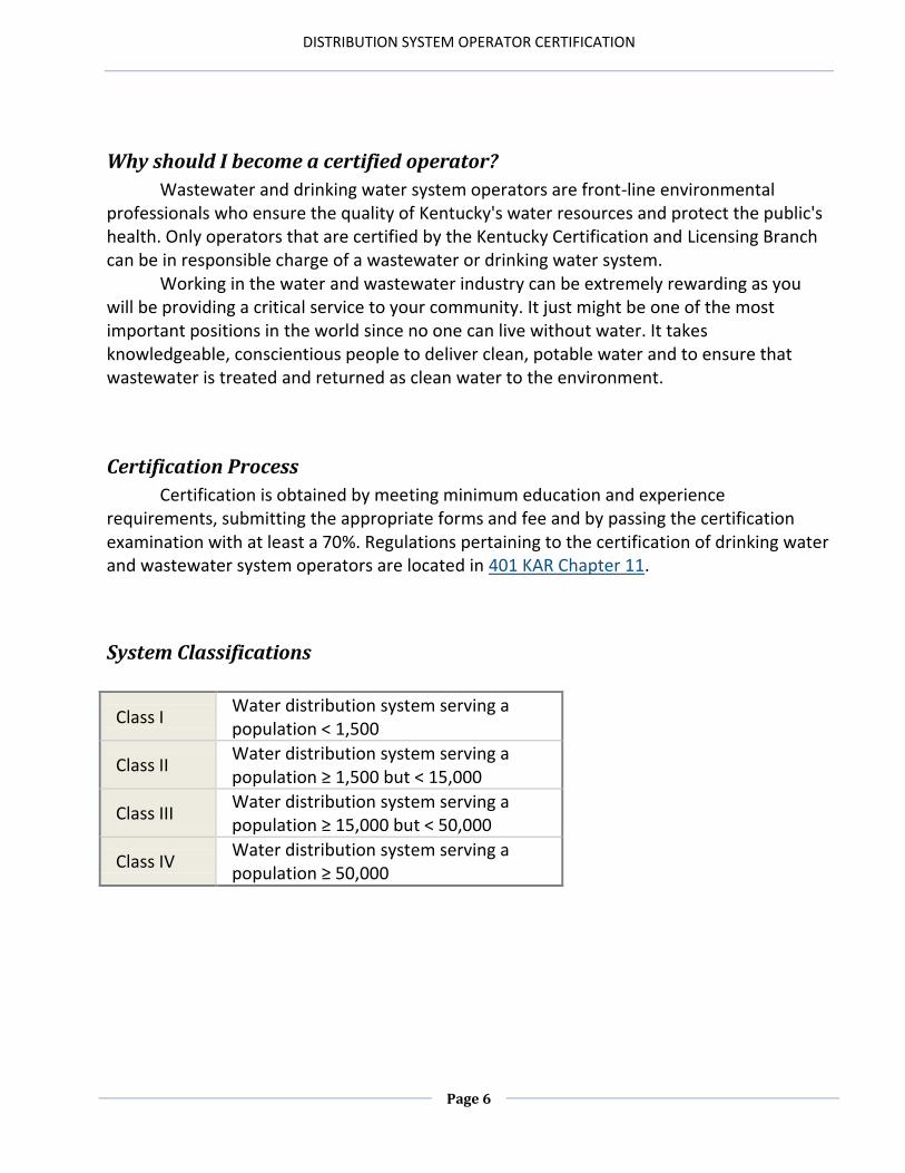
System Classifications
Class I Water distribution system serving a population < 1,500
Class II Water distribution system serving a population ≥ 1,500 but < 15,000
Class III Water distribution system serving a population ≥ 15,000 but < 50,000
Class IV Water distribution system serving a population ≥ 50,000
Operators in training certifications are available for each certification type. An individual can apply for an OIT license that is one level higher and of the same type as the certification that the individual currently holds. An individual may also apply for an entry level OIT certification. OITs must pass the appropriate operator certification exam and work under the responsible charge of a mentor. To apply for the exam, individuals must submit the following to the Certification and Licensing Branch:
Education and Experience Documentation Form;
Registration Form for Exams and Training;
The appropriate fee; and
A letter from the applicant’s mentor. The letter from the mentor must include: o A commitment to oversee the applicant’s work after the applicant
becomes an OIT; o A commitment to mentor the applicant as long as the applicant is under
the mentor’s direct responsible charge; o Verification that the mentor is not currently mentoring any other OITs;
and o Confirmation that the mentor holds a certification license that is equal
to or greater than the certification level required to serve in primary responsibility of the facility where the mentor and prospective OIT works.
Class I High School Diploma or GED and One (1) year of acceptable operation of a water distribution system shall be required.
Class II High School Diploma or GED and Two (2) years of acceptable operation of a water distribution system shall be required with Six (6) months in a water distribution system serving a population ≥ 1,500.
Class III
High School Diploma or GED and Three (3) years of acceptable operation of a water distribution system with One (1) year of that experience in a water distribution system serving a population ≥ 1,500.
Class IV Baccalaureate degree in engineering, science or equivalent is required and One (1) year of acceptable operation of a water distribution system serving a population ≥ 15,000.
DISTRIBUTION SYSTEM OPERATOR CERTIFICATION
Page 8
FACT SA Wastewater Treatment Class I-OIT who operates a wastewater treatment plant owned by the operator that serves only one residence may have primary responsibility for that plant. All other OITs may not be in responsible charge of a facility unless they hold an additional certification license that does not have an OIT designation.
Certification Renewal or Maintenance Drinking water treatment, distribution and bottled water system certifications expire on June 30 of even-numbered years. Certifications shall remain valid until the expiration date, unless suspended, revoked or replaced by a higher classification certificate before that date. Certificates issued between Jan. 1 and June 30 of a renewal year will be issued to include the next two-year renewal period. Failure to renew before July 1 of the renewal year will result in the expiration of certification and a late fee assessment. The certificate shall terminate if not renewed on or before December 31 of the year the certification expired. Certified operators with expired certificates shall not be in responsible charge of a drinking water or wastewater facility.
Certified operators (excluding OIT certificates) may renew their license(s) electronically through the cabinet Web site using the E-Search link or by submitting the Application for Certification Renewal and the appropriate fee to the Division of Compliance Assistance, Certification and Licensing Branch, 300 Fair Oaks Lane, Frankfort, KY 40601.
Certified operators who are designated an Operator in Training may renew a certification without examination if the operator has:
Satisfied the continuing education requirements; Earned the required years of operational experience; Submitted an Education and Experience Documentation form verifying his or
her experience; Submitted a letter of recommendation from a mentor; and Submitted a completed Application for Certification Renewal form and the renewal
fee to the cabinet or has renewed the certification electronically on the cabinet's Web site.
Drinking water treatment, distribution and bottled water certified operators training hours shall be completed for each renewal during the two (2) year period immediately prior to the certificate expiration date. Certified operators holding a treatment, distribution and/or bottled water certificate shall complete the required number of cabinet-approved training hours for the highest certificate held in lieu of completing the required number of continuing education hours required for both certificates.
Reminder -- Continuing education hours earned prior to certification shall not count toward certificate renewal.
Operator Ethics – Standards of Professional Conduct for Certified Operators In order to safeguard the life, health, and welfare of the public and the environment and to establish and maintain a high standard of integrity in the certified operator profession, standards of professional conduct apply to persons certified in accordance with 401 KAR Chapter 11. These standards state:
(a) A certified operator shall, during the performance of operational duties, protect the
safety, health, and welfare of the public and the environment; (b) A certified operator shall use reasonable care and judgment in the performance of
operational duties; (c) If a certified operator’s judgment is overruled by an employer under circumstances in
which the safety, health, and welfare of the public or the environment are endangered, the certified operator shall inform the employer of the possible consequences;
(d) A certified operator shall be objective, truthful, and complete in applications, reports, statements, and testimony provided to the cabinet; and
(e) A certified operator shall ensure the integrity of the samples that the operator collects, prepares, or analyzes so that results shall be a true representation of water quality.
The full set of standards is located in 401 KAR 11:020.
Certified operators who violate the standards in 401 KAR 11:020 are subject to disciplinary actions which include but are not limited to:
(a) Probation of the operator's certification for a specified period of time, not to exceed one (1) year;
(b) Suspension of the operator's certification for a specified period of time, not to exceed four (4) years, during which the certification shall be considered void;
(c) Revocation of the operator's certification; (d) Civil or criminal penalties; or (e) A combination of the disciplinary actions listed above.
Disciplinary actions are outlined in 401 KAR 11:050, Section 4. All regulations related to the certification of wastewater and drinking water operators are located in 401 KAR Chapter 11. A copy of the regulations is located in the appendix of this manual and it is recommended that you become familiar with the regulations that govern your profession.
DISTRIBUTION SYSTEM OPERATOR CERTIFICATION
Page 10
Key Definitions
Operator means a person involved in the operation of a wastewater treatment plant, wastewater collection system, drinking water treatment plant, or drinking water distribution system. (401 KAR 11:001) Water Distribution System is defined as the portion of the water supply in which water is conveyed from the water plant or other supply point to the premises of a consumer or a system of piping and ancillary equipment, which is owned or operated by an established water system independent of the water supply system from which the potable water is purchased. Ethics are defined as a code of morality or a system of moral principles governing the appropriate conduct for a person or group. System Classifications are used in determining regulatory standards and compliance requirements for each drinking water system. Public water system is a water system for the provision of water to the public for human consumption and the system has at least 15 service connections or regularly serves an average of at least 25 individuals a year.
Community water system is a public water system that serves at least 15 service connections used by year-round residents or regularly serves at least 25 year–round residents. Non-community water system is a public water system that serves at least 15 service connections used by persons less than year–round or serves an average of at least 25 individuals at least 60 days per year but less than year–round.
Transient non-community water system is a non-community water system that does not regularly serve at least 25 of the same persons over 6 months per year. (Example – gas stations, parks, resorts, restaurants, etc. with their own water systems. ) Non-transient non-community water system is a non-community water system that does not regularly serve at least 25 of the same persons over 6 months per year. Example – schools, factories, hospitals, etc., with their own water system.
Semi-public water system is a water system made available for drinking or domestic use that serve more than three families but does not qualify as a public water system. Semi-public water systems are commercial facilities that serve food or drink to the public and
DISTRIBUTION SYSTEM OPERATOR CERTIFICATION
Page 11
shall meet the requirements of 401 KAR 8:020. Semi-public water systems are not required to have certified operators. Monthly Operator Report (MOR) is a system’s monthly performance report for regulatory compliance. It must be submitted to the Division of Water in Frankfort no later than 10 days after the end of the month for which the report is filed. KAR – Kentucky Administrative Regulations are the regulations set forth by the Commonwealth of Kentucky, some of which regulate public water systems (Chapter 8, 11). KRS – Kentucky Revised Statutes are the laws that govern the Commonwealth of Kentucky. SDWA – Safe Drinking Water Act was passed by the United States Congress in 1974 to protect public health by regulating the nation’s public drinking water supply. The law was amended in 1986 and again in 1996 and requires many actions to protect drinking water and its sources: rivers, lakes, reservoirs, springs, and groundwater wells. This act authorizes the United States Environmental Protection Agency (US EPA) to set national health-based standards for drinking water to protect against both naturally occurring and manmade contaminants that may be found in drinking water. The federal operator certification requirement was established by this act. AI # - Agency Interest Number is the number that the Kentucky Environmental Protection Cabinet and the Division of Compliance Assistance (operator certification program) uses to track all activities pertaining to an individual or group involving environmental or regulatory compliance activities. AWOP – Area Wide Optimization Program is a national program whose goal is to maximize public health protection through optimization of existing conventional surface water treatment utilities. AWOP was developed by the EPA’s Technical Support Center as a non-regulatory, voluntary approach to microbial control using optimization tools to focus on operational changes to improve the drinking water quality. Goals are set that go beyond the regulatory requirements for conventional surface water treatment plants for settled water, filtered water and disinfection.
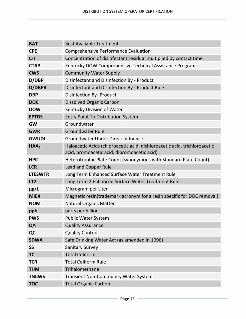
List of Key Acronyms
AOC Assimilable Organic Carbon – low molecular weight dissolved organic carbon (DOC) that is readily consumed by bacteria leading to growth.
BAC Biologically Active Carbon
DISTRIBUTION SYSTEM OPERATOR CERTIFICATION
Page 12
BAT Best Available Treatment
CPE Comprehensive Performance Evaluation
C-T Concentration of disinfectant residual multiplied by contact time
CTAP Kentucky DOW Comprehensive Technical Assistance Program
CWS Community Water Supply
D/DBP Disinfectant and Disinfection By - Product
D/DBPR Disinfectant and Disinfection By - Product Rule
HPC Heterotrophic Plate Count (synonymous with Standard Plate Count)
LCR Lead and Copper Rule
LTESWTR Long Term Enhanced Surface Water Treatment Rule
LT2 Long Term 2 Enhanced Surface Water Treatment Rule
µg/L Microgram per Liter
MIEX Magnetic resin(trademark acronym for a resin specific for DOC removal)
NOM Natural Organic Matter
ppb parts per billion
PWS Public Water System
QA Quality Assurance
QC Quality Control
SDWA Safe Drinking Water Act (as amended in 1996)
SS Sanitary Survey
TC Total Coliform
TCR Total Coliform Rule
THM Trihalomethane
TNCWS Transient Non-Community Water System
TOC Total Organic Carbon
DISTRIBUTION SYSTEM OPERATOR CERTIFICATION
Page 13
Treated Water considered no later than the combined filter influent
TTHM Total Trihalomethanes (chloroform, bromodichloromethane, dibromochloromethane, and bromoform)
USGS United States Geological Survey
UV Ultraviolet Light
UV 254 Ultraviolet wavelength at 254 nanometers
VA Vulnerability Assessment
VOC Volatile Organic Contaminant
WHPA Wellhead Protection Area
WTP Water Treatment Plant
Ethics
1. noun – the study of moral standards and how they affect conduct. 2. plural noun – a code of morality, a system of moral principles governing the appropriate conduct for a person or group. Your job as a distribution system operator has a direct impact on the health of the people who consume your water. Failure to obtain a Bac-T sample from a problem area or worse yet, writing down false readings, ruins your reputation, puts your future credibility in jeopardy, puts your career choice at risk, could lead to incarceration and potentially could cause someone who ingests your water to become sick or die. Nationally, more and more certified operators are being prosecuted for unethical or dishonorable behavior in the workplace. Water treatment and distribution in some areas have become a practice of notating the “right” numbers. If the “right” numbers are turned into the regulatory agency, visits from these regulatory agencies would probably not be as frequent or involved as they would be if valid or honest numbers were turned in. Our job is to protect the consuming public and provide potable water to each and every one of them, not satisfy regulatory numbers. Take pride in your work and in your ethical behavior.
DISTRIBUTION SYSTEM OPERATOR CERTIFICATION
Page 14
Chapter 1 Review
1. Operator certification became federally mandated in ________. 2. A public water system is defined as having ____ service connections or serves at least
_______ people year round. 3. Is it possible to obtain a Distribution Class III – OIT certification if the applicant does not
currently hold a valid Distribution Class II certification?
4. After June 30th of even-numbered years, an operator has months to renew before their certification terminates.
5. Certified operators who violate the standards in 401 KAR 11:020 are subject to disciplinary actions which include but are not limited to ______________; ______________;______________; ______________; or ______________.
6. The federal law that operator certification falls under is the _______.
DISTRIBUTION SYSTEM OPERATOR CERTIFICATION
Page 15
Answers for Chapter 1 Review 1. 1996 2. 15, 25 3. No 4. 6 5. Probation of the operator's certification for a specified period of time, not to exceed
one (1) year; Suspension of the operator's certification for a specified period of time, not to exceed four (4) years, during which the certification shall be considered void; Revocation of the operator's certification; Civil or criminal penalties; or A combination of the disciplinary actions listed above.
6. SDWA
DISTRIBUTION SYSTEM OPERATOR CERTIFICATION
Page 17
Chapter 2: WATER QUALITY
Chapter 2 Objectives: 1. Explain pH, DBPs, HPE’s, and Turbidity. 2. Understand the steps a distribution system operator must engage in to maintain or
improve water quality. 3. Identify the importance of pH as it relates to water quality. 4. Understand chemical reactions. 5. Explain how halogenated disinfection byproducts are formed. 6. Define corrosion and scaling. 7. Explain the purpose of maximum contaminant level goals (MCLGs).
DISTRIBUTION SYSTEM OPERATOR CERTIFICATION
Page 18
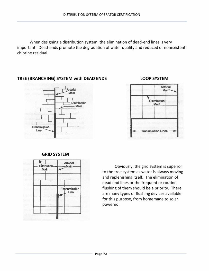
Water quality in the distribution system is initially determined by the effectiveness of the treatment operation that supplies that system. Actually improving the quality of the water after it enters the distribution system is usually not a viable endeavor. The water delivered to the consumer will be of a lesser quality than what it was when it entered the system. How much the water quality degrades is largely the responsibility of the distribution operator. The challenge of the distribution operator is to maintain the quality of the water from the treatment facility to the consumer’s tap. This is best accomplished by developing a strategy of developing and maintaining a distribution system that is clean, biologically and chemically stable, while protecting it from events and situations that will degrade the water quality to an unsuitable level. This is NOT an easy task, and a practical working knowledge of system design, shortcomings, and practical solutions is necessary to maintain water quality to an acceptable level. This will make it necessary for the distribution operator to have a rudimentary knowledge of water chemistry, hydraulics, biology and water quality parameters.
Pathogens
Pathogens are disease causing organisms. Waterborne diseases are usually caused by the presence of bacteria, viruses or protozoa. Their origin could be a shortcoming in the treatment process or they could enter a distribution system through a cross-connection, line installation or repair, intrusion, biofilms or an opening to the outside environment. Poor operational and maintenance practices or excessive water age will allow these pathogens to reproduce and could cause serious and even fatal consequences to ensue. Disinfection residuals need to be maintained to control the growth of microorganisms in our distribution system, whether they are pathogenic or not. Large disinfectant demands reduce the residual disinfectant levels and should be investigated immediately. There are some pathogenic organisms that are extremely resistant to most current disinfection practices and allowed to flourish could bring about dire health concerns to our consuming public. The challenge for distribution operators is to prevent the entry and to minimize the growth of the entities that can harm the health of the people who consume the water that is ingested from our distribution systems. Currently, coliform sampling is conducted to indicate the likely presence of harmful pathogenic organisms. A Heterotrophic Plate Count (a.k.a. a Standard Plate Count) can measure microbial bacterial growth, and used over time can be a viable and useful indicator of distribution water quality.
DISTRIBUTION SYSTEM OPERATOR CERTIFICATION
Page 19
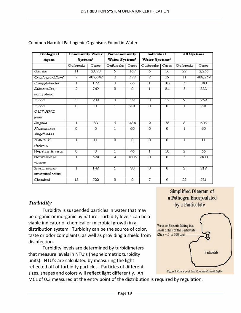
Common Harmful Pathogenic Organisms Found in Water
Turbidity
Turbidity is suspended particles in water that may be organic or inorganic by nature. Turbidity levels can be a viable indicator of chemical or microbial growth in a distribution system. Turbidity can be the source of color, taste or odor complaints, as well as providing a shield from disinfection.
Turbidity levels are determined by turbidimeters that measure levels in NTU’s (nephelometric turbidity units). NTU’s are calculated by measuring the light reflected off of turbidity particles. Particles of different sizes, shapes and colors will reflect light differently. An MCL of 0.3 measured at the entry point of the distribution is required by regulation.
DISTRIBUTION SYSTEM OPERATOR CERTIFICATION
Page 20
Higher turbidity levels in the distribution system should be identified and corrected immediately because they could very well be an indication of water quality degradation.
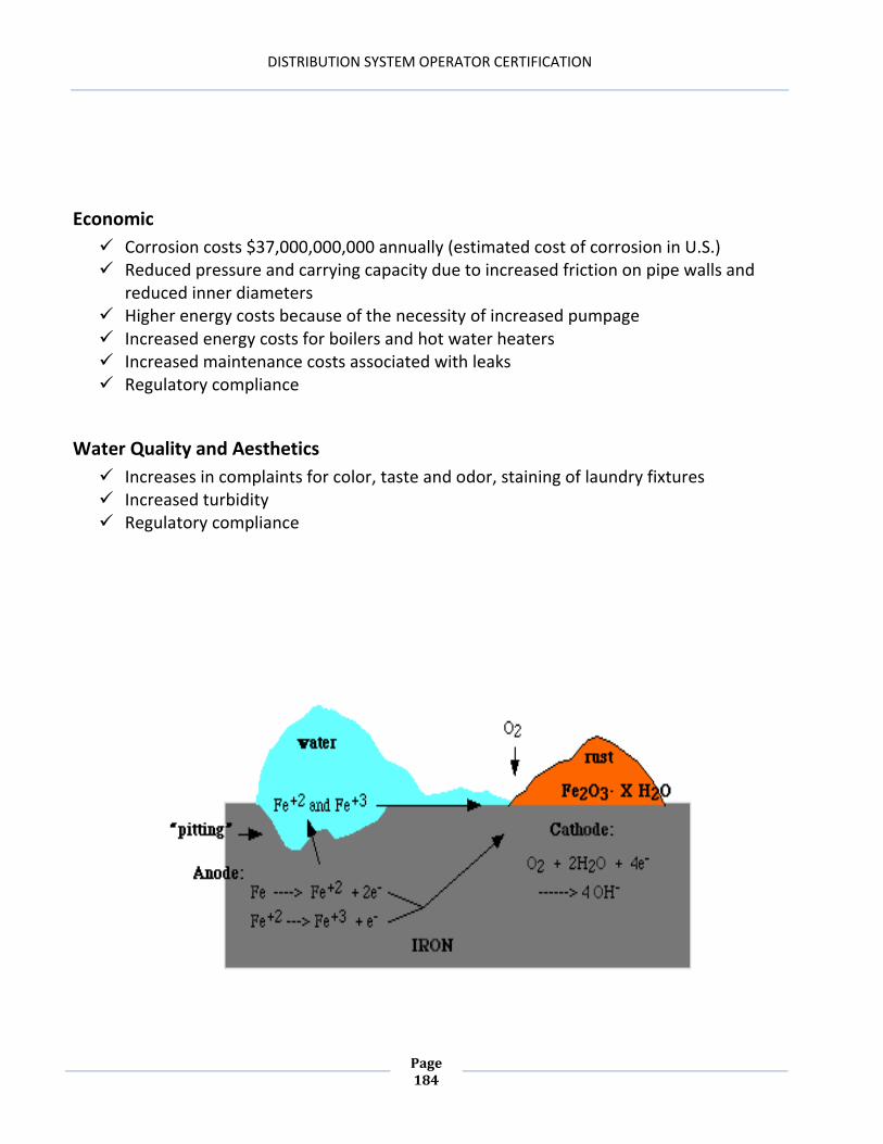
Corrosion/Scaling
Corrosion is the deterioration of a substance due to its environment. In the distribution system, corrosion is the decomposition of metallic components due to the chemical and/or biological characteristics of the water that these components are always in contact with. Scaling is the deposition of calcium carbonate (CaCO³) on distribution piping, valves, meters, etc. This deposition results from chemically unstable water, due primarily to the relative concentrations of pH, alkalinity, total dissolved solids, temperature and hardness.
Disinfection By-products
When chlorine reacts with organics, the chemical reaction forms halogenated disinfection by products. These by products have been found to be carcinogenic or cancer causing. Some of the by products that are regulated are Trihalomethanes, Haloacetic Acids and Chlorite, among others. The formation of these chemical compounds is directly proportionate to the amount of disinfectant, organic carbon and time, occurring concurrently. The most effective means to prevent the formation of these substances is to optimize the entire treatment and distribution processes. The key is the removal of natural organic matter (NOM) entering the distribution system, reduce the disinfectant demand in the system and minimize the residency time or water age in the system. More to the point, we need to practice good operation and control of our systems.
pH
A measure of the hydrogen ion concentration. To put it another way, pH describes the relative acidity of the water. It is measured on a scale from 0 (zero) to 14 with a reading of 7 being neutral. A change in the pH of one number (example: from 5 to 6) is actually a tenfold change in the relative acidity of the water. pH affects disinfection, corrosion control, the deposition of scale and just about every reaction, biological and chemical, that occurs in our water. A basic comprehension of pH can provide a better understanding of why problems occur in some areas but not others.
Taste and Odor
Taste and odor can be the result of improper or incomplete treatment or a biological or chemical phenomenon that occurs in the distribution system. It is frequently associated
DISTRIBUTION SYSTEM OPERATOR CERTIFICATION
Page 21
with either the decomposition of organic matter or a host of other distribution system issues. Some taste and odor issues are directly attributable to inorganic contaminants, such as corrosion and scaling byproducts or chemical carryover from the treatment facility. Taste and odor issues are more noticeable in warmer weather and/or warmer water temperatures. All taste and odor issues should be reported to the treatment facility immediately or a small problem could accelerate into a large problem in a short period of time. If these issues are not addressed, they will only become worse with time. The best prevention of taste and odor problems is to keep them from occurring.
Hardness
Water that contains a high concentration of calcium or magnesium ions. These complaints should be reported to the treatment facility. Hard water makes the lathering of soap difficult, as well as its propensity to form a layer of scale on dishes, basins and fixtures. The deposition of scale on plumbing fixtures is calcium carbonate (CaCO3).
Air
Air can restrict the flow or, in some instances, act just like a closed valve in the distribution system. Air in the form of dissolved oxygen, can intensely accelerate the rate of corrosion. Sources of air should be identified immediately to prevent unfavorable results. Air relief valves installed at the high points of a distribution system will alleviate this problem.
Maintaining Water Quality in Distribution Systems
Proactive unidirectional flushing program Storage tank cleaning and maintenance program Minimization of residency time (water age) Limit dead ends and proactively flush the ones in place Disinfection of new and repaired installations Viable corrosion control program Cross-connection control programs Budgeted line replacement program Leak detection program Water quality monitoring program Communication with treatment personnel Water quality considerations in design and replacement upgrades Training Public relations
DISTRIBUTION SYSTEM OPERATOR CERTIFICATION
Page 22
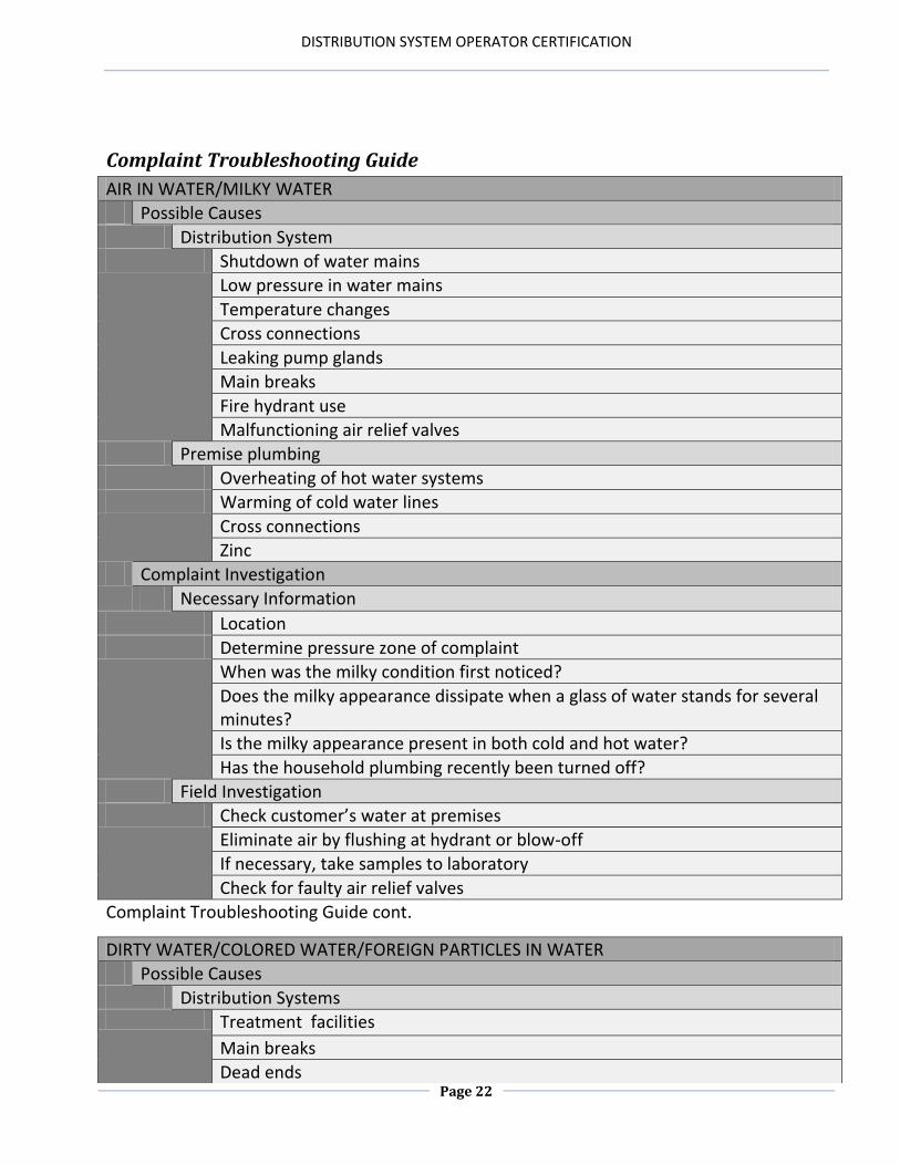
Complaint Troubleshooting Guide
AIR IN WATER/MILKY WATER
Possible Causes
Distribution System
Shutdown of water mains
Low pressure in water mains
Temperature changes
Cross connections
Leaking pump glands
Main breaks
Fire hydrant use
Malfunctioning air relief valves
Premise plumbing
Overheating of hot water systems
Warming of cold water lines
Cross connections
Zinc
Complaint Investigation
Necessary Information
Location
Determine pressure zone of complaint
When was the milky condition first noticed?
Does the milky appearance dissipate when a glass of water stands for several minutes?
Is the milky appearance present in both cold and hot water?
Has the household plumbing recently been turned off?
Field Investigation
Check customer’s water at premises
Eliminate air by flushing at hydrant or blow-off
If necessary, take samples to laboratory
Check for faulty air relief valves
Complaint Troubleshooting Guide cont.
DIRTY WATER/COLORED WATER/FOREIGN PARTICLES IN WATER
Possible Causes
Distribution Systems Treatment facilities
Main breaks
Dead ends
DISTRIBUTION SYSTEM OPERATOR CERTIFICATION
Page 23
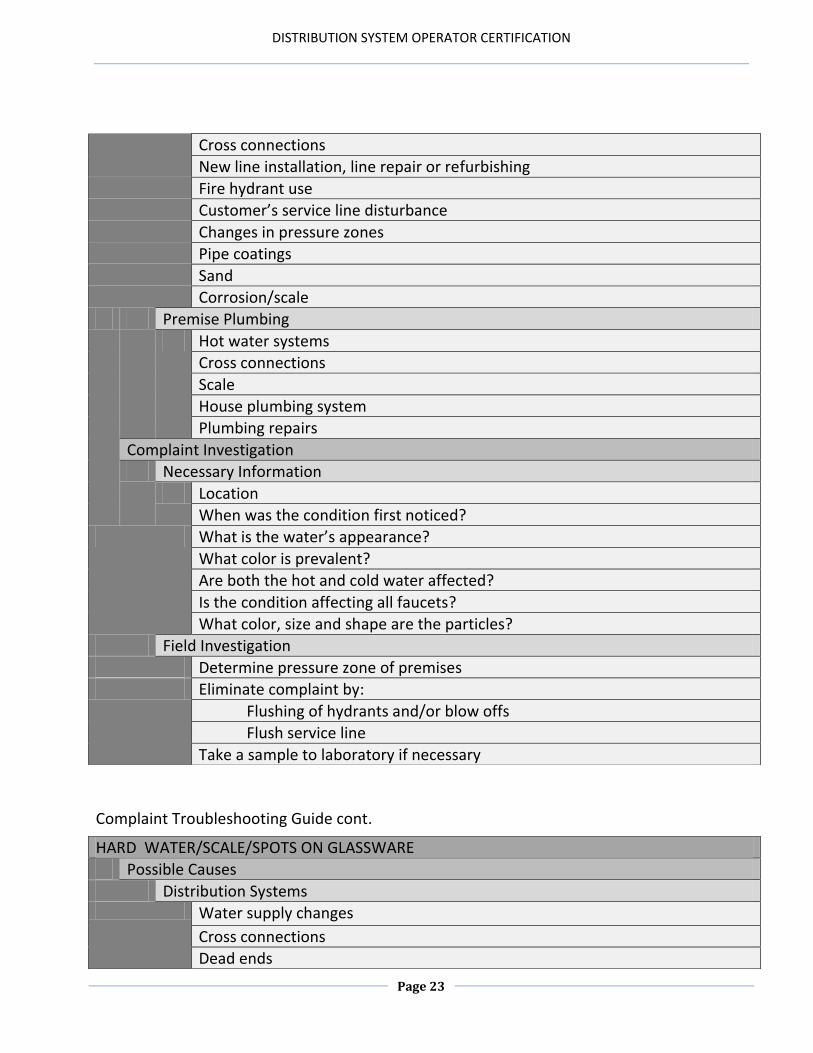
Complaint Troubleshooting Guide cont.
Cross connections
New line installation, line repair or refurbishing
Fire hydrant use
Customer’s service line disturbance
Changes in pressure zones
Pipe coatings
Sand
Corrosion/scale
Premise Plumbing
Hot water systems
Cross connections
Scale
House plumbing system
Plumbing repairs
Complaint Investigation
Necessary Information
Location
When was the condition first noticed?
What is the water’s appearance?
What color is prevalent?
Are both the hot and cold water affected?
Is the condition affecting all faucets?
What color, size and shape are the particles?
Field Investigation
Determine pressure zone of premises
Eliminate complaint by:
Flushing of hydrants and/or blow offs
Flush service line
Take a sample to laboratory if necessary
HARD WATER/SCALE/SPOTS ON GLASSWARE
Possible Causes
Distribution Systems Water supply changes
Cross connections
Dead ends
DISTRIBUTION SYSTEM OPERATOR CERTIFICATION
Page 24
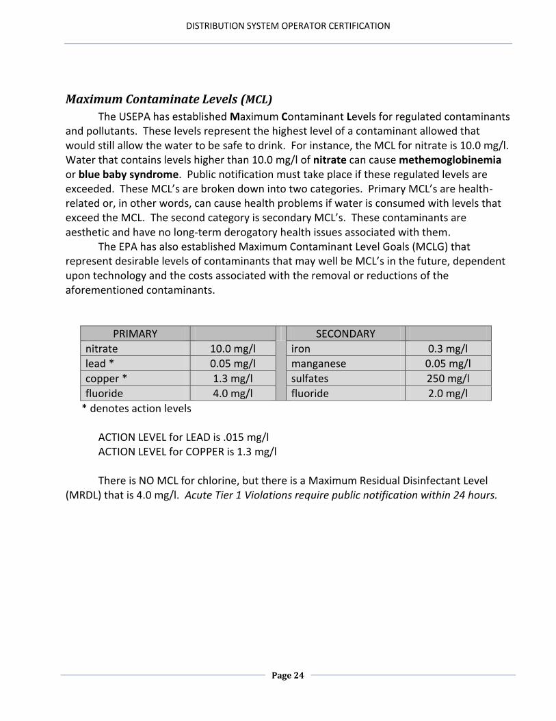
Maximum Contaminate Levels (MCL)
The USEPA has established Maximum Contaminant Levels for regulated contaminants and pollutants. These levels represent the highest level of a contaminant allowed that would still allow the water to be safe to drink. For instance, the MCL for nitrate is 10.0 mg/l. Water that contains levels higher than 10.0 mg/l of nitrate can cause methemoglobinemia or blue baby syndrome. Public notification must take place if these regulated levels are exceeded. These MCL’s are broken down into two categories. Primary MCL’s are health-related or, in other words, can cause health problems if water is consumed with levels that exceed the MCL. The second category is secondary MCL’s. These contaminants are aesthetic and have no long-term derogatory health issues associated with them.
The EPA has also established Maximum Contaminant Level Goals (MCLG) that represent desirable levels of contaminants that may well be MCL’s in the future, dependent upon technology and the costs associated with the removal or reductions of the aforementioned contaminants.
PRIMARY SECONDARY
nitrate 10.0 mg/l iron 0.3 mg/l
lead * 0.05 mg/l manganese 0.05 mg/l
copper * 1.3 mg/l sulfates 250 mg/l
fluoride 4.0 mg/l fluoride 2.0 mg/l
* denotes action levels
ACTION LEVEL for LEAD is .015 mg/l ACTION LEVEL for COPPER is 1.3 mg/l
There is NO MCL for chlorine, but there is a Maximum Residual Disinfectant Level
(MRDL) that is 4.0 mg/l. Acute Tier 1 Violations require public notification within 24 hours.
DISTRIBUTION SYSTEM OPERATOR CERTIFICATION
Page 25
Chapter 2 Review
1. A primary MCL refers to __________ related contaminants. 2. pH refers to the ___________ ion concentration of water. 3. Taste and odor issues as well as chemical reactions are exacerbated in _______ water. 4. _______________ is an electrochemical process that can cause leaching and other health related problems. 5. DBPs are caused by the reaction of _________ and ________. 6. Hardness is caused by high concentrations of or in the water.
DISTRIBUTION SYSTEM OPERATOR CERTIFICATION
Page 26
Answers for Chapter 2 Review
1. Health
2. Hydrogen
3. Warmer
4. Corrosion
5. Chlorine, organics
6. Calcium, magnesium ions
DISTRIBUTION SYSTEM OPERATOR CERTIFICATION
Page 27
Chapter 3: STORAGE
Chapter 3 Objectives 1. Describe the state regulations related to drinking water storage, operation, and
maintenance. 2. Explain the difference between the two types of maximum contaminant levels (MCLs). 3. Describe the three types of storage and the associated design features. 4. Explain why excessive water age is one of the most important factors related to water
quality deterioration. 5. Explain the two ways to address water age issues. 6. Identify the chemical, biological, and physical issues related to water quality problems. 7. Demonstrate the ability to calculate conversions, area, and volume related to water storage.
DISTRIBUTION SYSTEM OPERATOR CERTIFICATION
Page 28
Traditionally, finished water storage facilities have been designed to equalize water demands, reduce pressure fluctuations in the distribution system and provide reserves for firefighting, power outages and other emergencies. Some storage facilities have been operated to provide adequate pressure and have been kept full in order to be prepared for emergency conditions. Additionally, some storage facilities have been designed such that the high water level is below the hydraulic grade line of the system, making water turnover extremely difficult. If the hydraulic grade line of the system drops significantly, very old water may enter the system. If tanks are kept full yet are underutilized, the stored water ages and water quality is frequently compromised. Purpose of Storage: To meet all consumer demands Storage Quantity: Ensure an adequate supply for fire protection, peak usage periods, distribution maintenance, plant shutdown, major leaks, pressure maintenance, or any other consumer needs. Quality: Provide pathogen-free water that is also free from inorganic precipitates, biological activity, corrosion byproducts, taste, odor, color, turbidity, disinfection-by-products and any other factor that is detrimental to the health or aesthetic properties of the water. Under-storage: limits the ability to get the necessary quantity of water to the consumer when needed. Can allow pressure drops during peak usage if sufficient quantities aren’t maintained. Over-storage: can lead to water quality degradation due to the water age or lack of turnover.
Ideally, the operator needs to maintain the minimal amount of water necessary to meet demand on a daily basis in order to prevent water quality degradation and residual chlorine depletion due to a lack of turnover.
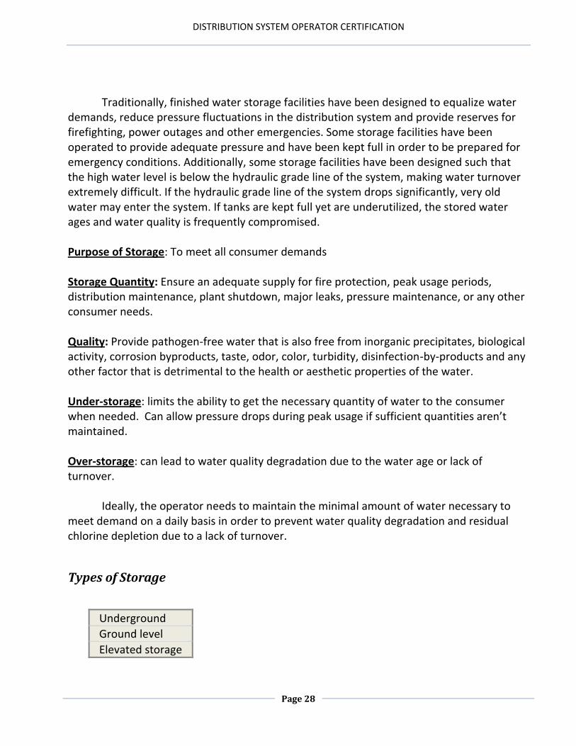
Types of Storage
Underground
Ground level
Elevated storage
DISTRIBUTION SYSTEM OPERATOR CERTIFICATION
Page 29
Design Features
Storage tanks should be: Covered to prevent contamination
Vented to relieve vacuum conditions
Screened to prevent entry of birds, rodents, etc.
Screened and flappered overflows that extend to or below ground level and be directed away from the tank foundation, businesses, homes, etc.
Protected against corrosion and its by-products.
Built and maintained to ensure structural integrity
Operation and Maintenance
Inspection: coatings (paint), security, safety, corrosion protection, stratification, vents, overflows, telemetry, valve operation, etc. Inspection can be accomplished by draining the facility, diving, remote sensing or float down. Monitoring: total coliform, disinfectant residuals, pH, temperature, DBP’s, bacteria concentration ( heterotrophic or standard plate counts), corrosion, scale, nitrification (especially in systems using chloramines), taste, odor, iron, manganese, turbidity, gases, etc. Cleaning and Disinfection: Draining and cleaning of tanks should be performed when necessary and should be considered on an annual basis. Painting and coatings should be evaluated at least every five to ten years.
DISTRIBUTION SYSTEM OPERATOR CERTIFICATION
Page 30
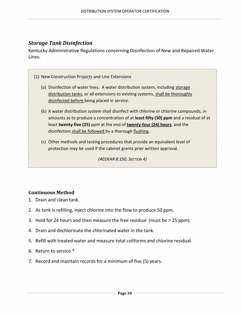
(1) New Construction Projects and Line Extensions
(a) Disinfection of water lines. A water distribution system, including storage
distribution tanks, or all extensions to existing systems, shall be thoroughly
disinfected before being placed in service.
(b) A water distribution system shall disinfect with chlorine or chlorine compounds, in
amounts as to produce a concentration of at least fifty (50) ppm and a residual of at
least twenty-five (25) ppm at the end of twenty-four (24) hours, and the
disinfection shall be followed by a thorough flushing.
(c) Other methods and testing procedures that provide an equivalent level of
protection may be used if the cabinet grants prior written approval.
(401KAR 8:150, SECTION 4)
Storage Tank Disinfection
Kentucky Administrative Regulations concerning Disinfection of New and Repaired Water Lines:
Continuous Method
1. Drain and clean tank.
2. As tank is refilling, inject chlorine into the flow to produce 50 ppm.
3. Hold for 24 hours and then measure the free residual (must be > 25 ppm).
4. Drain and dechlorinate the chlorinated water in the tank.
5. Refill with treated water and measure total coliforms and chlorine residual.
6. Return to service *
7. Record and maintain records for a minimum of five (5) years.
DISTRIBUTION SYSTEM OPERATOR CERTIFICATION
Page 31
Spray/Swab Method
1. Drain and clean tank
2. Fill tank with a measured volume (i.e. 1 ft deep)
3. Dose pre-measured volume at 250 ppm
4. Swab or spray interior walls and ceiling with the chlorine solution.
5. Repeat process no sooner than 1 hour later
6. Allow an additional 30 minutes contact time
7. Drain and dechlorinate the chlorinated water
8. Refill with treated water and measure total coliforms and chlorine residual
9. Return to service *
10. Record and maintain records for a minimum of five years after fulfilling bacteriological sample requirements
* If a new installation is involved, the continuous method must be used and negative coliform results must be obtained before being placed into service.
Operational Issues
Calibrate and maintain the accuracy of the telemetry and valving systems.
Drawdown tanks as far as feasible before refilling so water turnover is achieved.
Design the tank with a smaller diameter riser to increase velocity and increase mixing.
Contemplate retrofitting older designs with separate inlets and outlets to induce
water circulation and mixing.
DISTRIBUTION SYSTEM OPERATOR CERTIFICATION
Page 32
Water Age
Traditionally many water storage facilities were built with a common inlet and outlet. Water quality problems associated with water storage can be classified as chemical, microbiological or physical.
Excessive water age is probably the most important factor related to water quality deterioration. Long detention times can be conducive to microbial growth and chemical changes. Excessive water age is usually caused by 1) under utilization and 2) short circuiting within the storage facility. Poor mixing (including stratification) can make water quality problems worse by creating zones within the water storage facility where the water age significantly exceeds the average water age throughout your system.
Summary of Water Quality Problems Associated with Finished Water Storage Facilities
CHEMICAL ISSUES BIOLOGICAL ISSUES PHYSICAL ISSUES
Disinfectant Decay Microbial Regrowth* Corrosion
Chemical Contaminants* Nitrification* Temperature/Stratification
DBP Formation* Pathogen Contamination* Sediment*
Taste and Odors Taste and Odors
* Water quality issues with direct potential health impact
“Old” water, seldom if ever turned over
Occasionally turned over when demand is high
Frequent turnover, “fresh” water
Single influent, effluent pipe
DISTRIBUTION SYSTEM OPERATOR CERTIFICATION
Page 33
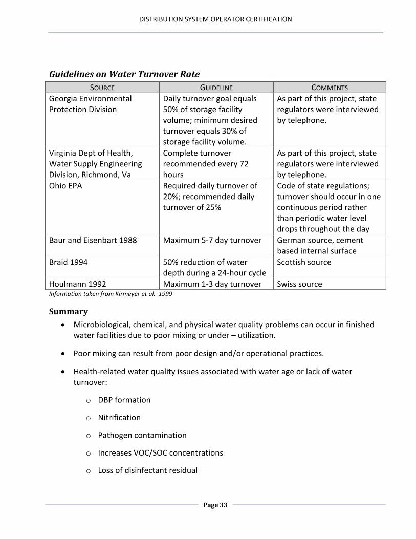
Guidelines on Water Turnover Rate
SOURCE GUIDELINE COMMENTS
Georgia Environmental Protection Division
Daily turnover goal equals 50% of storage facility volume; minimum desired turnover equals 30% of storage facility volume.
As part of this project, state regulators were interviewed by telephone.
Virginia Dept of Health, Water Supply Engineering Division, Richmond, Va
Complete turnover recommended every 72 hours
As part of this project, state regulators were interviewed by telephone.
Ohio EPA Required daily turnover of 20%; recommended daily turnover of 25%
Code of state regulations; turnover should occur in one continuous period rather than periodic water level drops throughout the day
Baur and Eisenbart 1988 Maximum 5-7 day turnover German source, cement based internal surface
Braid 1994 50% reduction of water depth during a 24-hour cycle
Scottish source
Houlmann 1992 Maximum 1-3 day turnover Swiss source Information taken from Kirmeyer et al. 1999
Summary
Microbiological, chemical, and physical water quality problems can occur in finished water facilities due to poor mixing or under – utilization.
Poor mixing can result from poor design and/or operational practices.
Health-related water quality issues associated with water age or lack of water turnover:
o DBP formation
o Nitrification
o Pathogen contamination
o Increases VOC/SOC concentrations
o Loss of disinfectant residual
DISTRIBUTION SYSTEM OPERATOR CERTIFICATION
Page 34
Area and Volume
Area: a two-dimensional measurement (length X width). Area is a measurement of the amount of space on the surface on an object. Since the square is the basis by which these measurements are made, the units used to express this surface space are in square feet (ft2). Volume: a three-dimensional measurement (length X width X height). Volume is used to measure the holding capacity of an object. The basis of measuring this capacity is the cube expressed as cubic feet (ft3).
Volume Examples
1. The cross-sectional area of a 12 inch pipe is _________? .785 x 1 ft x 1 ft = .785 ft2 2. The volume of a standpipe that is 20 feet in diameter and 60 feet in height is ______? .785 x 20ft x 20ft x 60 ft = 18,840 ft3
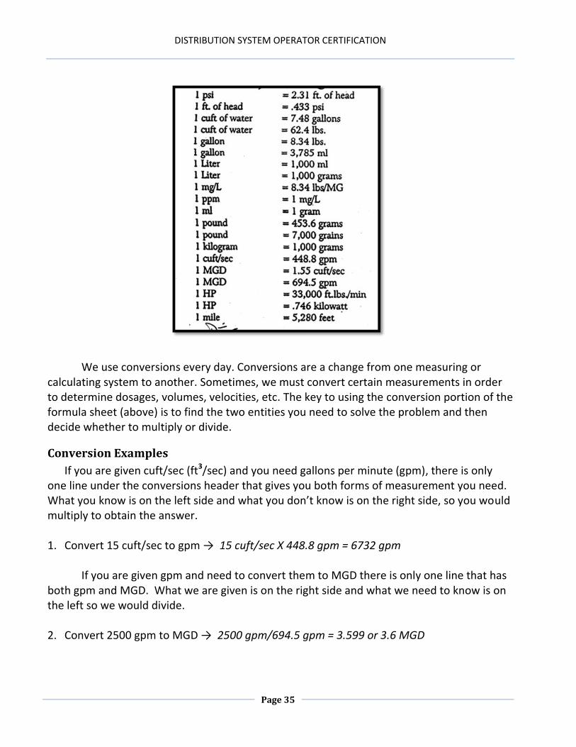
Conversions
In our industry, we don’t usually use measurements in cubic feet. In order to convert cubic feet to gallons, we multiply the number of cubic feet by 7.48 gallons. To use the previous problem as an example we would multiply 18, 840 ft3 by 7.48 gallons.
18,840 ft3 X 7.48 gallons = 140,923.2 gallons
feet X feet = square feet (ft 2 )
feet X feet X feet = cubic feet (ft3 )
DISTRIBUTION SYSTEM OPERATOR CERTIFICATION
Page 35
We use conversions every day. Conversions are a change from one measuring or
calculating system to another. Sometimes, we must convert certain measurements in order to determine dosages, volumes, velocities, etc. The key to using the conversion portion of the formula sheet (above) is to find the two entities you need to solve the problem and then decide whether to multiply or divide.
Conversion Examples
If you are given cuft/sec (ft3/sec) and you need gallons per minute (gpm), there is only one line under the conversions header that gives you both forms of measurement you need. What you know is on the left side and what you don’t know is on the right side, so you would multiply to obtain the answer. 1. Convert 15 cuft/sec to gpm → 15 cuft/sec X 448.8 gpm = 6732 gpm If you are given gpm and need to convert them to MGD there is only one line that has both gpm and MGD. What we are given is on the right side and what we need to know is on the left so we would divide. 2. Convert 2500 gpm to MGD → 2500 gpm/694.5 gpm = 3.599 or 3.6 MGD
DISTRIBUTION SYSTEM OPERATOR CERTIFICATION
Page 36
Math Review
If we need to find the area (a two-dimensional measurement) in a rectangle, we simply multiply length x width.
If we need the cross – sectional area of a circle, we multiply .785 x diameter in feet x
diameter in feet, which gives us an answer in square feet (ft²).
2-d Area Examples
1. What would the area be of a basin that measures 6 feet wide by 10 feet long? Area = Length in feet X Width in feet Area = 6 ft X 10 ft Area = 60 square feet (ft²)
2. What would the cross- sectional area of a 24-inch circle be? Area = .785 X diameter in feet X diameter in feet Area = .785 X 2 ft X 2 ft Area = 3.14 ft²
DISTRIBUTION SYSTEM OPERATOR CERTIFICATION
Page 37
To find volume (the size of a three – dimensional space enclosed within or occupied by an object) in a rectangle, we account for the third measurement which would be height or depth.
To find the volume of a pipe or cylinder, we multiply .785 x diameter in feet x diameter in feet x height or depth in feet.
3-d Area Examples
1. A sedimentation basin measures 18 feet wide by 26 feet long by 12 feet in depth. What is the volume of this basin? Volume = Length (in feet) X Width (in feet) X Depth or Height (in feet) Volume = 26 ft X 18 ft X 12 ft Volume = 5,616 cubic feet (ft³)
2. How many cubic feet of water would a 24-inch pipeline that measures 1500 feet in length contain? Volume = .785 X diameter (in feet) X diameter (in feet) X length (in feet) Volume = .785 X 2 ft X 2 ft X 1500 ft Volume = 4,710 cubic feet (ft³)
DISTRIBUTION SYSTEM OPERATOR CERTIFICATION
Page 38
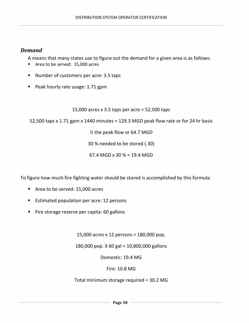
Demand
A means that many states use to figure out the demand for a given area is as follows: Area to be served: 15,000 acres
Number of customers per acre: 3.5 taps
Peak hourly rate usage: 1.71 gpm
15,000 acres x 3.5 taps per acre = 52,500 taps
52,500 taps x 1.71 gpm x 1440 minutes = 129.3 MGD peak flow rate or for 24 hr basis
½ the peak flow or 64.7 MGD
30 % needed to be stored (.30)
67.4 MGD x 30 % = 19.4 MGD
To figure how much fire fighting water should be stored is accomplished by this formula:
Area to be served: 15,000 acres
Estimated population per acre: 12 persons
Fire storage reserve per capita: 60 gallons
15,000 acres x 12 persons = 180,000 pop.
180,000 pop. X 60 gal = 10,800,000 gallons
Domestic: 19.4 MG
Fire: 10.8 MG
Total minimum storage required = 30.2 MG
DISTRIBUTION SYSTEM OPERATOR CERTIFICATION
Page 39
Chapter 3 Review
1. Chemical reactions occur more quickly in ______ water.
2. Tank ______is an important consideration in reducing water age.
3. A lack of water turnover causes a rapid depletion of ______ residuals.
4. A storage facility should turn the water completely over every ______ hours.
5. Every time a tank is taken out of service for repair or cleaning, it must be disinfected at a dosage of ______ ppm, held for ______ hours and maintain a residual of ______ ppm.
6. Monkeys Eyebrow’s 4800 residents use on average 190,000 gallons of water a day. What would the average daily water demand per resident be for the month of June?
a. 40 gallons b. 175 gallons c. 1187.5 gallons d. 467.6 gallons
DISTRIBUTION SYSTEM OPERATOR CERTIFICATION
Page 40
Answers for Chapter 3 Review 1. Warmer
2. Turnover
3. Chlorine
4. 72
5. 50, 24, 25
6. a
DISTRIBUTION SYSTEM OPERATOR CERTIFICATION
Page 41
Chapter 4: DISINFECTION
Chapter 4 Objectives
1. Explain the purpose of disinfection. 2. Explain the relation between dosage demand and residual. 3. Identify the chemicals and/or processes used to disinfect the water. 4. Identify the factors that affect the disinfection process. 5. Demonstrate competence with several disinfection calculations. 6. Describe the process for pipeline disinfection. 7. Explain the regulations associated with drinking water disinfection. 8. Explain how to properly disinfect a leak site. 9. Explain how to keep a repair or replacement of pipe as contamination free as possible. 10. Explain what regulatory parameters are involved when repairing a line. 11. Explain how to assure that the disinfectant is reaching all areas of the entire pipe.
DISTRIBUTION SYSTEM OPERATOR CERTIFICATION
Page 42
Purpose of Disinfection
To kill pathogens
To provide a residual safeguard
Disinfection is the selective destruction or inactivation of pathogenic organisms. Water, as well as being the universal solvent, also provides a favorable environment for the growth of many biological organisms, some of which are capable of causing disease. The primary purpose of disinfection is to kill or inactivate pathogens in the water. Pathogens are disease-causing organisms. Many of the largest disease outbreaks in history can be attributed to waterborne pathogens. Because of their propensity to kill large numbers of the population, these and all other pathogens should be controlled in the treatment process. In fact, the processes of coagulation, flocculation, sedimentation and filtration were developed to control pathogenic contamination in drinking water. Pathogens, which are found in either the forms of bacteria, viruses, or protozoa, are not “removed” by disinfection. Some are killed, some are temporarily inactivated, and some are not affected at all by chemical disinfectants or biocides. Because of this fact, it is mandatory to optimize our disinfection processes.
The secondary purpose of disinfection is to provide a residual safeguard. After regulatory standards are met at the treatment process, it will degrade as it moves through the distribution system. The degree of water quality degradation is affected by its chemical and biological composition, as well as the physical condition of the distribution system it travels through. Proper management, which includes flushing, cleaning, pressure maintenance, backflow prevention, monitoring and line replacement programs is necessary to prevent substantial water quality degradation in the distribution system. We maintain disinfectant residuals to provide a safeguard against pathogenic contamination that could develop in the distribution system. The regulated minimum disinfectant residual requirements are 0.2 mg/l for chlorine and 0.5 mg/l for chloramines. The maximum residual disinfectant level (MRDL) allowable in a distribution system is 4.0 mg/l for chlorine and chloramine and 0.8 mg/l for chlorine dioxide. Water quality degradation can be indirectly determined by calculating the disinfectant demand:
DEMAND = DOSAGE – RESIDUAL
DISTRIBUTION SYSTEM OPERATOR CERTIFICATION
Page 43
When demand increases in the distribution system, the cause of this increase should be determined and rectified immediately. Increasing the disinfectant feed will only cover up any problems in the system, and it will make the development of halogenated disinfection by products (carcinogens) much more problematic. It can also lead to compromised corrosion control (lead, copper and other metal leaching; red or black water; leaks ;pressure issues), as well as increased operating costs.
Types of Disinfectants
Chlorine
Chlorine is the most widely used disinfectant. Chlorine is effective at pathogenic inactivation as well as providing a residual safeguard in the distribution system. Chlorine is also a viable oxidizer that allows for the precipitation of substances, including iron and manganese prior to settling or filtration. Chlorine volatizes gases, such as hydrogen sulfide, methane and benzene, and will also reduce organic related taste and odor and color causing compounds. When combined with organics for a significant length of time, the formation of trihalomethanes and haloacetic acids can be an issue. THM’s and HAA5’s are suspected to be carcinogenic, and their levels are federally regulated.
DISTRIBUTION SYSTEM OPERATOR CERTIFICATION
Page 44
Chlorine Gas
Chlorine is 100 % available gas that is fed out of pressurized tanks or cylinders that actually contain both liquid and gas. The liquid-to-gas concentration is temperature-dependent with higher temperatures yielding a higher concentration of liquid. The atmospheric expansion ratio from liquid to gas is 460:1, and a fusible plug is placed in the bottom of the cylinders and designed to melt between 154º - 165º Fahrenheit in order to exhaust the chlorine as a gas. In the event of a leak on the bottom of a cylinder, it should be rolled over to prevent an escape of the liquid. Chlorine is greenish–yellow in color, and it is 2.5 times heavier than air. It is not flammable, but will readily support combustion. Chlorine gas is corrosive when combined with moisture and usually lowers the pH of water. Whenever chlorine is fed at a rate of > 40 lbs. a day in 150 lb. cylinders, two or more cylinders must be connected together to prevent freezing of the feed system. Though small leaks can be detected with a 10% ammonium hydroxide solution and will show up with the appearance of a white cloud, leak repair kits, as well as SCBA equipment, should be kept just outside of the chlorine room to allow for quick access. The chlorine feed system is contained in a separate room that opens to the outdoors. It must be designed with an exhaust fan and vent located near the floor that activates prior to entry and is capable of exchanging the atmosphere in the chlorine room within one minute. A window for visual inspection and a door equipped with panic hardware are also necessities pertinent to chlorine rooms. Evacuation and emergency plans, as well as up-to-date operator training, are essential for the safe operation of these rooms. Inhalation of chlorine gas can be fatal and repeated brief contact can permanently damage the lungs.
Calcium Hypochlorite
65 – 70 % available chlorine is manufactured as a powder as well as in granular form and a tablet. Calcium hypochlorite has a tendency to elevate the pH of water and is a weaker disinfectant than chlorine gas. It has a maximum shelf life of two years and degrades rapidly at that point, especially at higher temperatures. When in contact with oxidizers or organic compounds, a high flammability factor must be accounted for. Calcium hypochlorite should be stored in a clean, cool, dry areaway from other chemicals. It is used frequently used in distribution systems to disinfect new or repaired pipelines and storage facilities, as well in treatment facilities because of safety concerns about chlorine gas.
DISTRIBUTION SYSTEM OPERATOR CERTIFICATION
Page 45
Sodium Hypochlorite
More commonly referred to as bleach, this is 5.25 – 12 % available chlorine. Just as with calcium hypochlorite, sodium hypochlorite has a tendency to raise the pH of water and is a weaker disinfectant than both chlorine gas and calcium hypochlorite. Just as with all chlorine products, an acid is produced when in contact with water and is corrosive. The shelf life of sodium hypochlorite is 60 – 90 days and higher concentrations degrade more rapidly, so greater volumes of weaker solutions should be fed. This “bleach” is used for distribution system disinfection, as well as a primary disinfectant in some treatment facilities. Sodium hypochlorite should be stored in a cool, dark location because heat, metals, and time will cause it to degrade.
Chloramines
Chloramines are formed when water containing ammonia is chlorinated or when ammonia is added to water containing chlorine. It is an effective bactericide that produces fewer halogenated disinfection by – products, and it is generated on site. Chloramine is a weak disinfectant, and it is much less effective against viruses or protozoa than free chlorine. Chloramine lasts longer in a distribution system than chlorine, by some accounts up to 27 days. Used appropriately as a secondary disinfectant, it prevents bacterial regrowth in a distribution system.
Chlorine Dioxide
This is a pungent, reddish – yellow gas that is an effective disinfectant against waterborne microbes, including Cryptosporidium. It is an effective oxidizer with iron, sulfur compounds and certain taste and odor issues. It dissipates quickly as it reacts as it converts back to chlorine. Chlorine dioxide must be generated on – site and can be formed by combining gaseous chlorine with a 25% dosage of sodium chlorite. A stronger disinfectant than chlorine, it produces fewer halogenated by-products than does chlorine, but a major by-product is chlorite.
DISTRIBUTION SYSTEM OPERATOR CERTIFICATION
Page 46
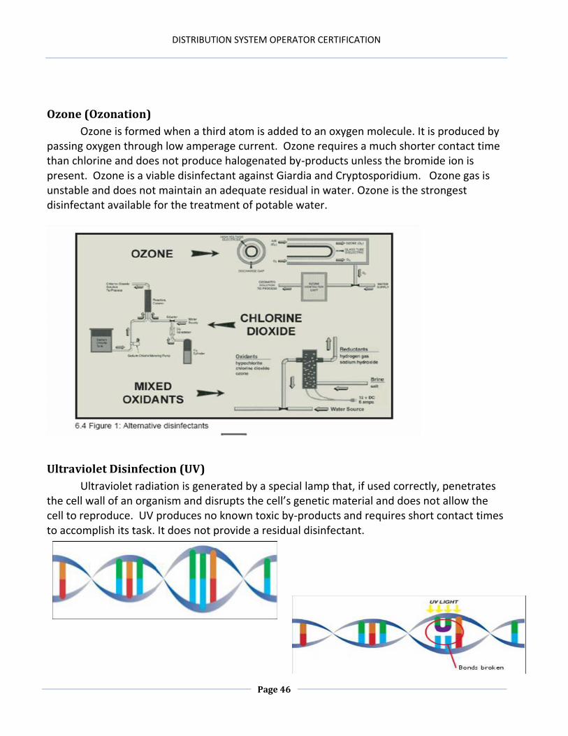
Ozone (Ozonation)
Ozone is formed when a third atom is added to an oxygen molecule. It is produced by passing oxygen through low amperage current. Ozone requires a much shorter contact time than chlorine and does not produce halogenated by-products unless the bromide ion is present. Ozone is a viable disinfectant against Giardia and Cryptosporidium. Ozone gas is unstable and does not maintain an adequate residual in water. Ozone is the strongest disinfectant available for the treatment of potable water.
Ultraviolet Disinfection (UV)
Ultraviolet radiation is generated by a special lamp that, if used correctly, penetrates the cell wall of an organism and disrupts the cell’s genetic material and does not allow the cell to reproduce. UV produces no known toxic by-products and requires short contact times to accomplish its task. It does not provide a residual disinfectant.
DISTRIBUTION SYSTEM OPERATOR CERTIFICATION
Page 47
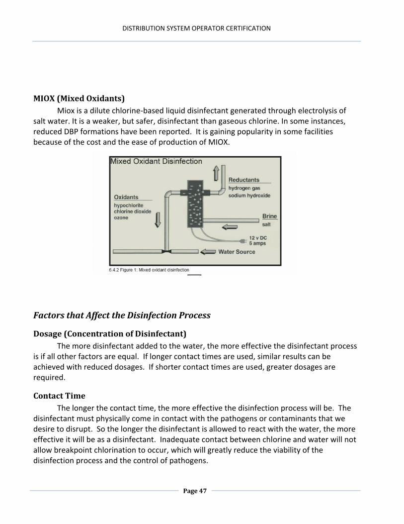
MIOX (Mixed Oxidants)
Miox is a dilute chlorine-based liquid disinfectant generated through electrolysis of salt water. It is a weaker, but safer, disinfectant than gaseous chlorine. In some instances, reduced DBP formations have been reported. It is gaining popularity in some facilities because of the cost and the ease of production of MIOX.
Factors that Affect the Disinfection Process
Dosage (Concentration of Disinfectant)
The more disinfectant added to the water, the more effective the disinfectant process is if all other factors are equal. If longer contact times are used, similar results can be achieved with reduced dosages. If shorter contact times are used, greater dosages are required.
Contact Time
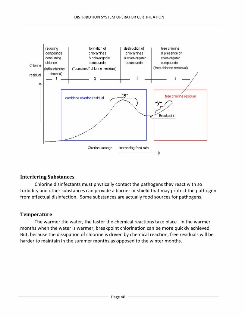
The longer the contact time, the more effective the disinfection process will be. The disinfectant must physically come in contact with the pathogens or contaminants that we desire to disrupt. So the longer the disinfectant is allowed to react with the water, the more effective it will be as a disinfectant. Inadequate contact between chlorine and water will not allow breakpoint chlorination to occur, which will greatly reduce the viability of the disinfection process and the control of pathogens.
DISTRIBUTION SYSTEM OPERATOR CERTIFICATION
Page 48
Interfering Substances
Chlorine disinfectants must physically contact the pathogens they react with so turbidity and other substances can provide a barrier or shield that may protect the pathogen from effectual disinfection. Some substances are actually food sources for pathogens.
Temperature
The warmer the water, the faster the chemical reactions take place. In the warmer months when the water is warmer, breakpoint chlorination can be more quickly achieved. But, because the dissipation of chlorine is driven by chemical reaction, free residuals will be harder to maintain in the summer months as opposed to the winter months.
DISTRIBUTION SYSTEM OPERATOR CERTIFICATION
Page 49
When chlorine is added to water, the following chemical reactions take place.
(Hypochlorous Acid == Hydrogen Ion + Hypochlorite Ion)
The Hypochlorous Acid and the Hypochlorite Ion are the compounds that inactivate or kill pathogens. Hypochlorous Acid is 100 X more effective than the Hypochlorite Ion. Both occur simultaneously in water with the concentrations of each compound being pH dependent.
Point of Application
The more thorough the mixing process, the quicker the chemical reaction will take place and the less contact time needed for effective disinfection. If we apply all of the chlorine in one end of a long pipeline before filling it with water, then when we do fill up the pipe with water all of the disinfectant will wash toward the other end of the pipeline. Adding a proportional amount to each pipe joint just before slowly filling the pipeline will provide a more thorough and effective means of disinfection.
DISTRIBUTION SYSTEM OPERATOR CERTIFICATION
Page 50
Disinfection Monitoring & Control
Disinfection Feed and Dosage Determination
The amount of disinfectant applied to the water is dependent upon the demand and the desired amount of residual to be carried into the distribution system. The total of demand + residual makes up the dosage required. Breakpoint chlorination should be practiced at all times to ensure that all demand is met and a free residual is established after adequate contact time. If using the slug method of disinfection, the operator will add an arbitrary amount of disinfectant and then mathematically determine if sufficient amounts of the disinfectant were added to achieve correct dosage requirements. For this type of application, the following formula is used:
ppm (or mg/l) = lbs. of chemical x % purity 8.34 x MG
Although the slug method works, it wastes chemical and therefore, money. A more feasible method is to first determine what dosage is required and then calculate the amount of chemical needed to obtain the desired results. The continuous flow method, which feeds the correct dosage of chemical into a flow of water, uses the following formula:
lbs of chemical/day = ppm (mg/l) X 8.34 X MGD % purity
When disinfecting a volume of water (no flow condition), such as when using the spray or swab method, the formula used would be:
lbs of chemical = ppm (mg/l) X 8.34 X MG % purity
When mixing a chlorine solution using calcium or sodium hypochlorite, the following
formula can be used to determine the strength of solution:
strength of solution = lbs of chlorine lbs of solution
DISTRIBUTION SYSTEM OPERATOR CERTIFICATION
Page 51
To express the strength of solution as a percentage of chlorine in the solution, one
would multiply the strength of solution by 100. The strength of solution can be multiplied by the pounds of solution fed to determine the pounds of chlorine fed. The pounds of solution fed can be determined by multiplying the gallons of solution fed by 8.34 (lbs).
For example, if 5 gallons of bleach (5.25% available) is mixed with 45 gallons of water to produce 50 gallons of solution, the strength of solution would be calculated as follows:
5 gal. of bleach X 8.34 lbs/gal X .0525 = 2.189 lbs of chlorine = .005
50 gal. of solution X 8.34 lbs/gal 417 lbs of solution
.005 is the decimal equivalent of .5% (.005 X 100)
If 40 gallons of the solution was fed: 40 gal X 0.005 = 0.2 lbs of chlorine fed
If the chemical being mixed into the solution is a liquid, then the final weight must be multiplied by the specific gravity of the liquid chemical to get the actual weight of the chemical being fed. This is because not all liquids weigh the same as water (8.34 lbs/gal).
If the 0.2 lbs of chlorine were fed into 5,000 gallons of water, the dosage could be calculated as follows:
DOSAGE (ppm or mg/l) = 0.2 lbs of chlorine = 4.79 or 4.8 ppm (mg/l) 8.34 X .005 MG
Bacteriological sampling is used to determine potential contamination problems allowing the system to notify the public to boil their water while system personnel can locate and rectify the cause of the problem. Just because bacteriological samples are negative for total coliforms does not mean the water is not contaminated. Heterotrophic (standard) Plate Counts are very useful monitoring tools for the disinfection process.
DISTRIBUTION SYSTEM OPERATOR CERTIFICATION
Page 52
Pipeline Disinfection
Operators should ensure that proper disinfection methods are followed to provide the maximum public health protection when installing and repairing pipelines that are intended for potable water service.
Inspection
Pipes and fittings should be examined for any damage with particular attention to joints. Any damage to the pipe ends or gaskets may result in leakage. The pipe sections should be clean and free of blemishes on the interior. Before placing a pipe in the trench it should be thoroughly inspected for contamination.
Sanitary Construction Methods
Sanitary procedures should be adopted whenever work is to be done to a pipeline. It may seem unnecessary or time prohibitive to perform these sanitary practices, but experience has shown that the steps actually save time because they reduce the bacteriological test failure rates. Keeping Pipes Clean and Dry
Keeping the pipe clean during installation is the single most important factor that results in successful disinfection. The interior of pipes must be protected during installation. Openings should be sealed with watertight plugs or coverings when the construction is halted and personnel are not present to ensure that contamination does not enter the pipe.
DISTRIBUTION SYSTEM OPERATOR CERTIFICATION
Page 53
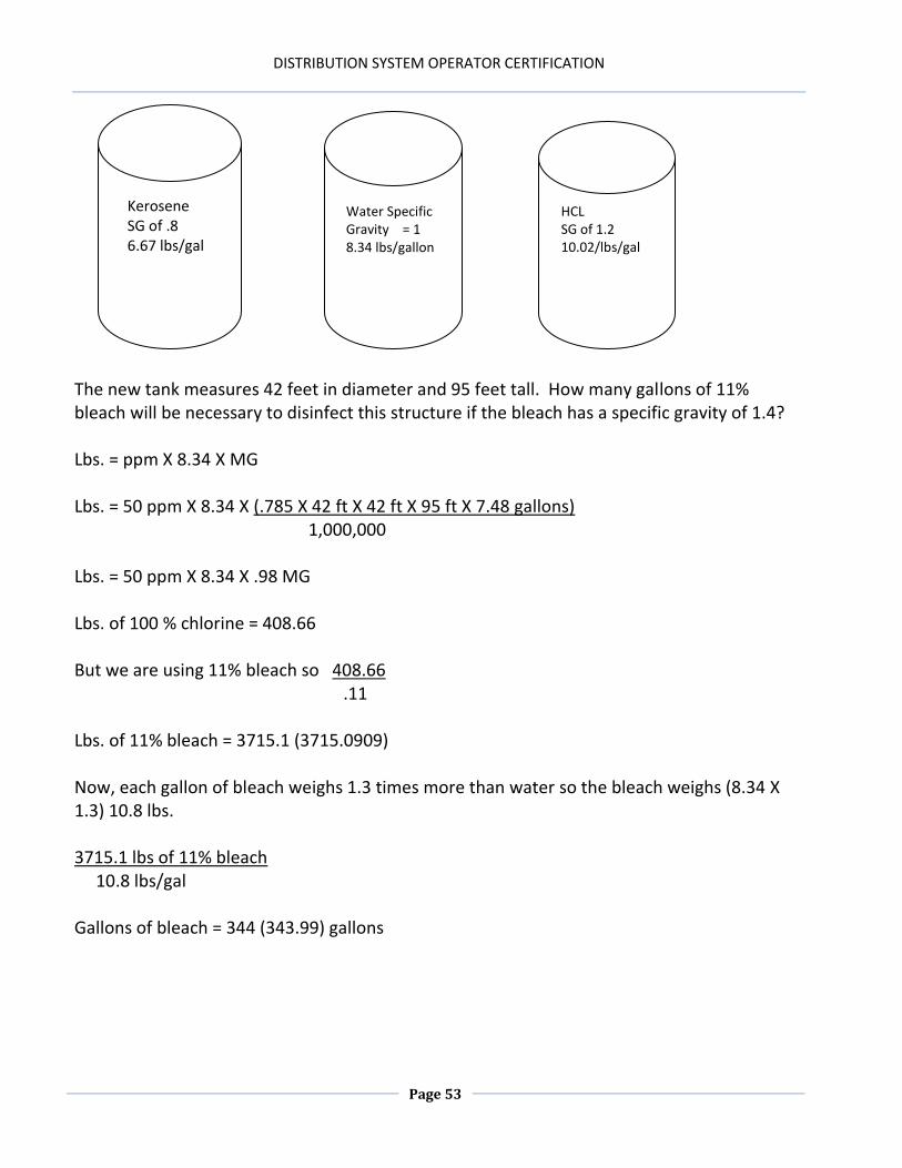
The new tank measures 42 feet in diameter and 95 feet tall. How many gallons of 11% bleach will be necessary to disinfect this structure if the bleach has a specific gravity of 1.4? Lbs. = ppm X 8.34 X MG Lbs. = 50 ppm X 8.34 X (.785 X 42 ft X 42 ft X 95 ft X 7.48 gallons) 1,000,000 Lbs. = 50 ppm X 8.34 X .98 MG Lbs. of 100 % chlorine = 408.66 But we are using 11% bleach so 408.66 .11 Lbs. of 11% bleach = 3715.1 (3715.0909) Now, each gallon of bleach weighs 1.3 times more than water so the bleach weighs (8.34 X 1.3) 10.8 lbs. 3715.1 lbs of 11% bleach 10.8 lbs/gal Gallons of bleach = 344 (343.99) gallons
HCL SG of 1.2 10.02/lbs/gal
Kerosene SG of .8 6.67 lbs/gal
Water Specific Gravity = 1 8.34 lbs/gallon
DISTRIBUTION SYSTEM OPERATOR CERTIFICATION
Page 54
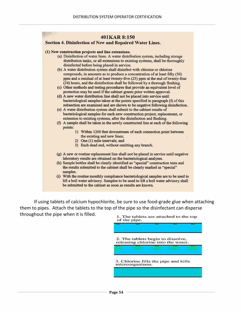
If using tablets of calcium hypochlorite, be sure to use food-grade glue when attaching them to pipes. Attach the tablets to the top of the pipe so the disinfectant can disperse throughout the pipe when it is filled.
DISTRIBUTION SYSTEM OPERATOR CERTIFICATION
Page 55
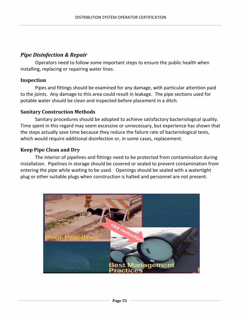
Pipe Disinfection & Repair
Operators need to follow some important steps to ensure the public health when installing, replacing or repairing water lines.
Inspection
Pipes and fittings should be examined for any damage, with particular attention paid to the joints. Any damage to this area could result in leakage. The pipe sections used for potable water should be clean and inspected before placement in a ditch.
Sanitary Construction Methods
Sanitary procedures should be adopted to achieve satisfactory bacteriological quality. Time spent in this regard may seem excessive or unnecessary, but experience has shown that the steps actually save time because they reduce the failure rate of bacteriological tests, which would require additional disinfection or, in some cases, replacement.
Keep Pipe Clean and Dry
The interior of pipelines and fittings need to be protected from contamination during installation. Pipelines in storage should be covered or sealed to prevent contamination from entering the pipe while waiting to be used. Openings should be sealed with a watertight plug or other suitable plugs when construction is halted and personnel are not present.
DISTRIBUTION SYSTEM OPERATOR CERTIFICATION
Page 56
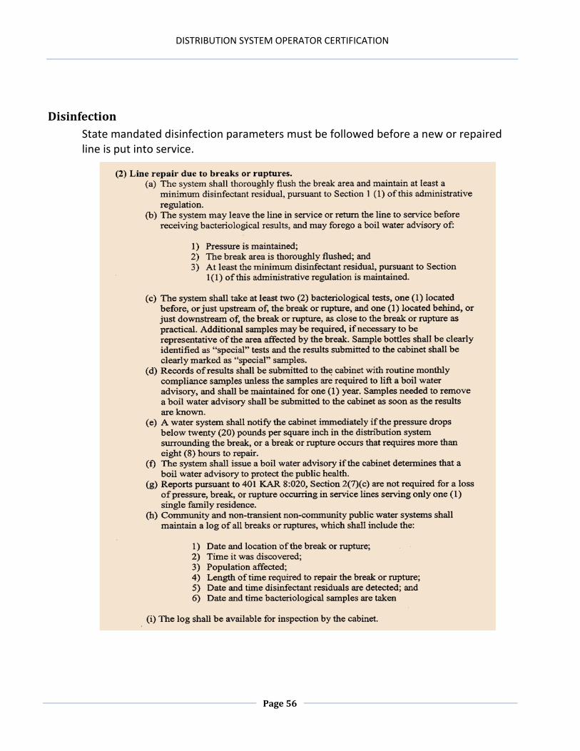
Disinfection
State mandated disinfection parameters must be followed before a new or repaired line is put into service.
DISTRIBUTION SYSTEM OPERATOR CERTIFICATION
Page 57
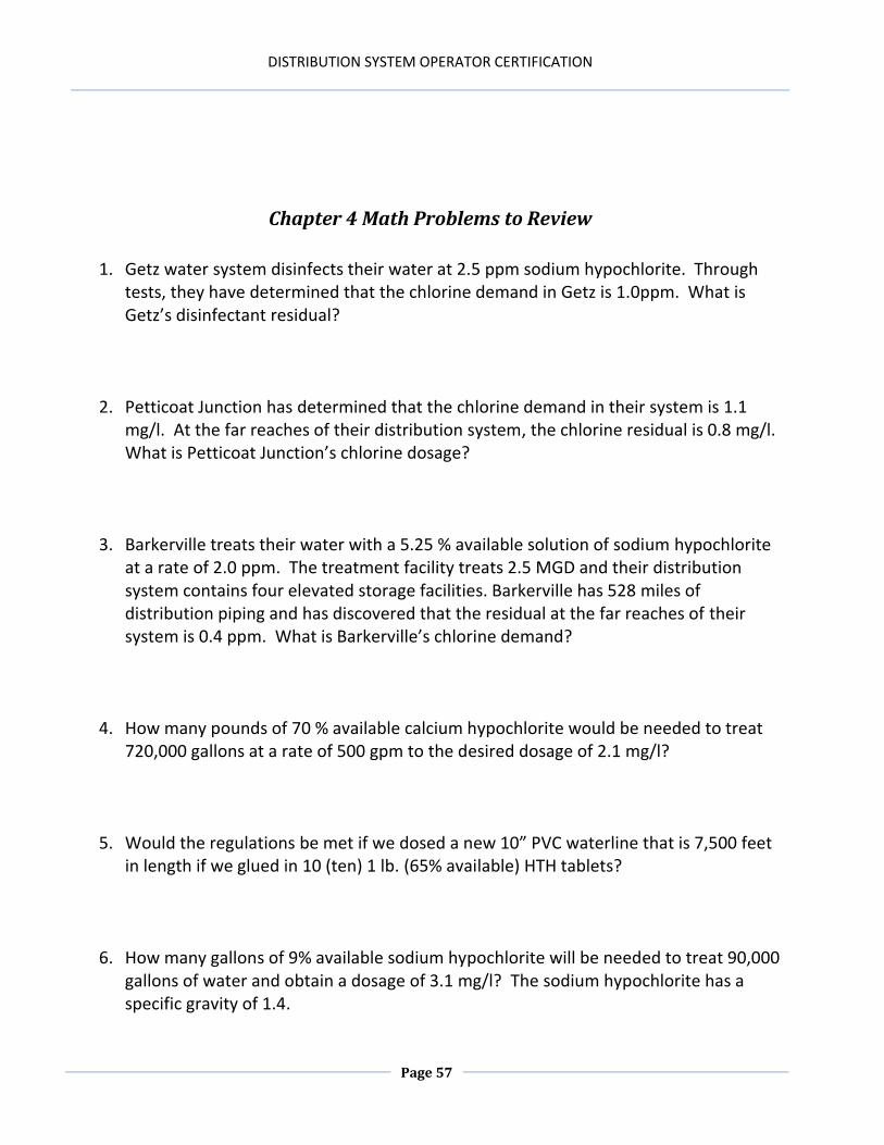
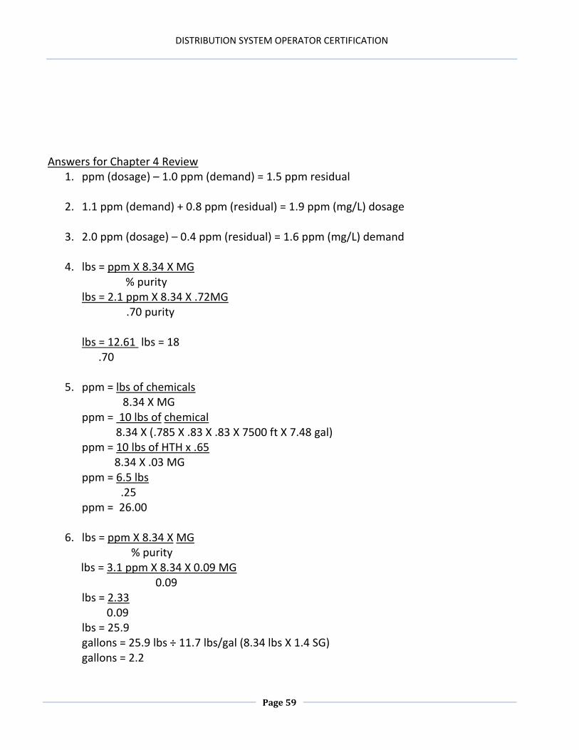
Chapter 4 Math Problems to Review
1. Getz water system disinfects their water at 2.5 ppm sodium hypochlorite. Through
tests, they have determined that the chlorine demand in Getz is 1.0ppm. What is Getz’s disinfectant residual?
2. Petticoat Junction has determined that the chlorine demand in their system is 1.1 mg/l. At the far reaches of their distribution system, the chlorine residual is 0.8 mg/l. What is Petticoat Junction’s chlorine dosage?
3. Barkerville treats their water with a 5.25 % available solution of sodium hypochlorite
at a rate of 2.0 ppm. The treatment facility treats 2.5 MGD and their distribution system contains four elevated storage facilities. Barkerville has 528 miles of distribution piping and has discovered that the residual at the far reaches of their system is 0.4 ppm. What is Barkerville’s chlorine demand?
4. How many pounds of 70 % available calcium hypochlorite would be needed to treat 720,000 gallons at a rate of 500 gpm to the desired dosage of 2.1 mg/l?
5. Would the regulations be met if we dosed a new 10” PVC waterline that is 7,500 feet in length if we glued in 10 (ten) 1 lb. (65% available) HTH tablets?
6. How many gallons of 9% available sodium hypochlorite will be needed to treat 90,000 gallons of water and obtain a dosage of 3.1 mg/l? The sodium hypochlorite has a specific gravity of 1.4.
DISTRIBUTION SYSTEM OPERATOR CERTIFICATION
Page 58
7. If we add 2 gallons of bleach with a specific gravity of 1.5 to 200 gallons of water, what would be the percent strength of this solution?
8. The second shift treatment operator in Mt. Airy used 8.5 lbs. of chlorine during his 8- hour shift. Mt Airy treats 4.5 MGD. What dosage did the second shift operator obtain during his shift?
9. If Hooterville doses its water at the treatment facility with 12.5 pounds of gaseous chlorine and the residual in the distribution system is 0.8 mg/l. What would the demand be if they treat 1 MGD?
10. If the concentration of the disinfectant is decreased then the _________ must be increased.
11. The strongest disinfectant for potable water disinfection is ________.
12. If your disinfectant residual is at least ____% of the total chlorine, then breakpoint has been achieved.
1. Identify the purpose of sampling. 2. Define a pathogen. 3. Describe the relationship between pathogens and coli forms. 4. Describe requirements relative to drinking water sampling. 5. Describe and explain proper drinking water sample collection techniques. 6. Describe the importance of representative sampling. 7. Define the relevance and necessity of check samples. 8. Denote disinfection test methods. 9. Define regulatory parameters for proper record keeping.
DISTRIBUTION SYSTEM OPERATOR CERTIFICATION
Page 62
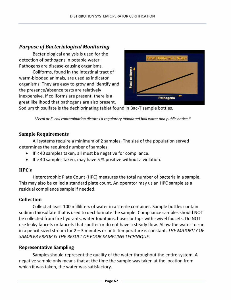
Purpose of Bacteriological Monitoring
Bacteriological analysis is used for the detection of pathogens in potable water. Pathogens are disease-causing organisms.
Coliforms, found in the intestinal tract of warm-blooded animals, are used as indicator organisms. They are easy to grow and identify and the presence/absence tests are relatively inexpensive. If coliforms are present, there is a great likelihood that pathogens are also present. Sodium thiosulfate is the dechlorinating tablet found in Bac-T sample bottles.
*Fecal or E. coli contamination dictates a regulatory mandated boil water and public notice.*
Sample Requirements
All systems require a minimum of 2 samples. The size of the population served determines the required number of samples.
If < 40 samples taken, all must be negative for compliance.
If > 40 samples taken, may have 5 % positive without a violation.
HPC’s
Heterotrophic Plate Count (HPC) measures the total number of bacteria in a sample. This may also be called a standard plate count. An operator may us an HPC sample as a residual compliance sample if needed.
Collection
Collect at least 100 milliliters of water in a sterile container. Sample bottles contain sodium thiosulfate that is used to dechlorinate the sample. Compliance samples should NOT be collected from fire hydrants, water fountains, hoses or taps with swivel faucets. Do NOT use leaky faucets or faucets that sputter or do not have a steady flow. Allow the water to run in a pencil-sized stream for 2 – 3 minutes or until temperature is constant. THE MAJORITY OF SAMPLER ERROR IS THE RESULT OF POOR SAMPLING TECHNIQUE.
Representative Sampling
Samples should represent the quality of the water throughout the entire system. A negative sample only means that at the time the sample was taken at the location from which it was taken, the water was satisfactory.
DISTRIBUTION SYSTEM OPERATOR CERTIFICATION
Page 63
Do NOT avoid suspected areas of poor water quality dead ends and low-use areas. Update sampling plans as the distribution system extends or recedes and include residential, commercial, industrial and educational sites.
Check Sampling
Within 24 hours of a positive sample notification, a system must collect 3 check samples: 1 from the original sample location and 1 within 5 service connections upstream and one within 5 service connections downstream.
Check samples are still considered compliance samples. If the system collects fewer than 5 samples a month for compliance, the month after a check sample incident the system MUST submit 5 compliance samples.
Special samples (line extensions, new lines, line breaks, etc) do NOT count toward compliance. BARF’s (bacteriological analysis report forms) must still be submitted with special samples even though they are NOT counted toward compliance.
Methods
Recordkeeping
Always fill out Chain of Custody documents for samples. BARF’s do NOT take the place of a Chain of Custody document. Bacteriological records must be maintained for 5 years. Sample labels, Chain of Custody documents and BARF’s should include the following: Collection date and time Type of disinfection Location code Name, address and PWSID Chlorine residual Signature of sampler
Multiple Tube Fermentation ColiBlue 24
Membrane Filtration Colitag
MMO – MUG Most Probable Number Colilert 18
MI agar Colilert
Coliscan Fluorocult
ONPG-MUG Colisure
DISTRIBUTION SYSTEM OPERATOR CERTIFICATION
Page 64
Chapter 5 Review
1. What temperature should the sample achieve? 2. Check samples must number ___ samples and be performed within ___ hours of a positive sample notification. 3. The number of samples taken is dependent upon ____. 4. _____ can be used in place of a compliance sample if minimum residual levels are not satisfied.
5. What needs to be on a chain of custody?
a) PWSID b) Samplers name c) Where the sample was taken d) All of the above
DISTRIBUTION SYSTEM OPERATOR CERTIFICATION
Page 65
Answers for Chapter 5 Review 1. The temperature of the water in the main. 2. 3, 24 3. Population 4. HPC’s 5. d
DISTRIBUTION SYSTEM OPERATOR CERTIFICATION
Page 66
DISTRIBUTION SYSTEM OPERATOR CERTIFICATION
Page 67
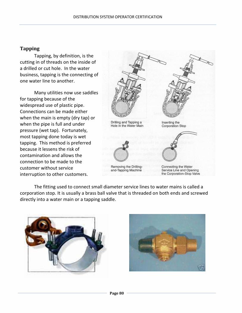
Chapter 6: PIPES & SERVICES
Chapter 6 Objectives
1. Identify important infrastructure issues related to distribution systems. 2. Differentiate between the different types of pipes and the variables to consider when
selecting a pipe. 3. Describe the importance and need of detailed management plans and distribution
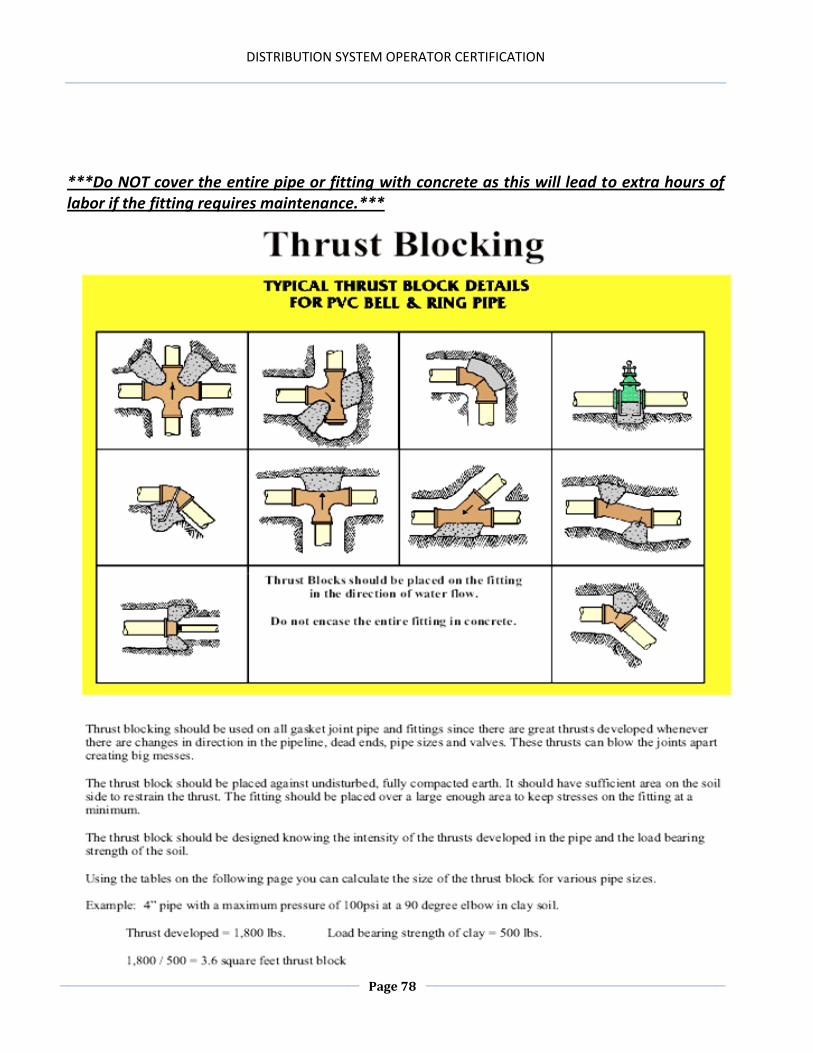
system maps as they relate to operational concerns and pipe installation. 4. Describe the regulatory requirements related to mandated inclusions. 5. Explain proper pipe installation techniques, bedding practices, and thrust blocking
techniques. 6. Differentiate between the types of distribution systems (tree, loop, grid, dead end
lines) and describe the shortcomings and strengths of each type of system. 7. Describe the process of pipe disinfection and repair related to pressure and leak
testing of new and repaired water lines. 8. Describe the benefits of unidirectional flushing compared to conventional flushing. 9. Explain the sanitary practices related to pipe repair. 10. Calculate math computations related to area and volume of water distribution
systems (sedimentation basins, storage tanks, pipes, etc.) and related to basic disinfection practices.
11. Explain the regulations and tests associated with improving water quality. 12. Identify the characteristics and pathogens related to biofilms. 13. Differentiate between repair and rehabilitation options of water distribution pipes
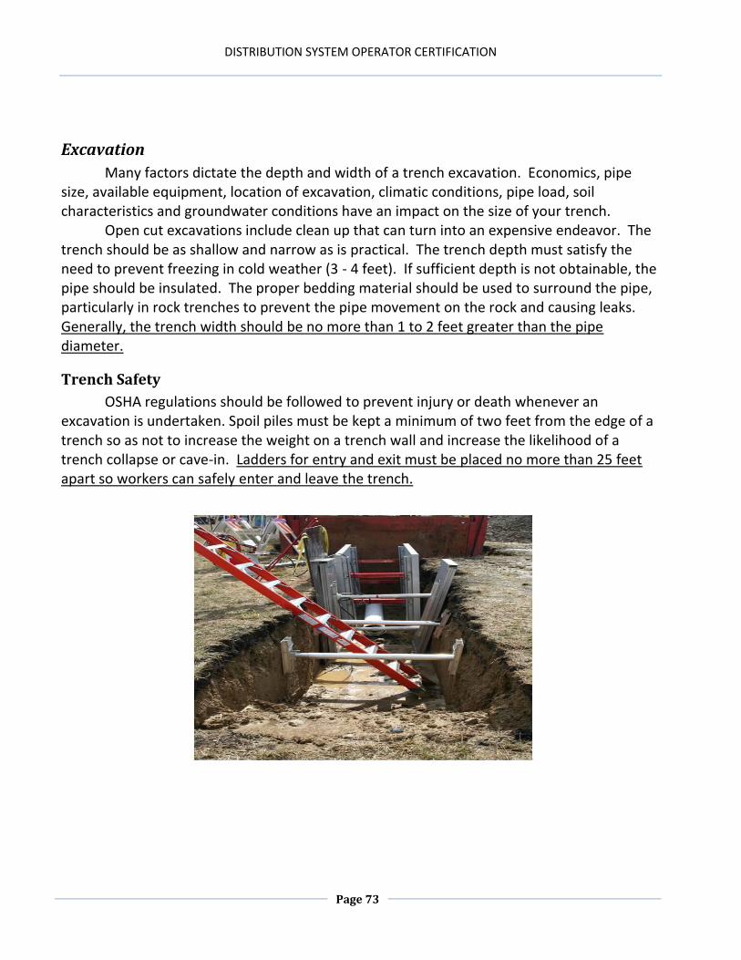
(e.g., pipe bursting, slip lining, pigging, pipe jacking, etc.) 14. Explain the factors related to the depth and width of trench excavation and identify
basic trench safety practices.
DISTRIBUTION SYSTEM OPERATOR CERTIFICATION
Page 68
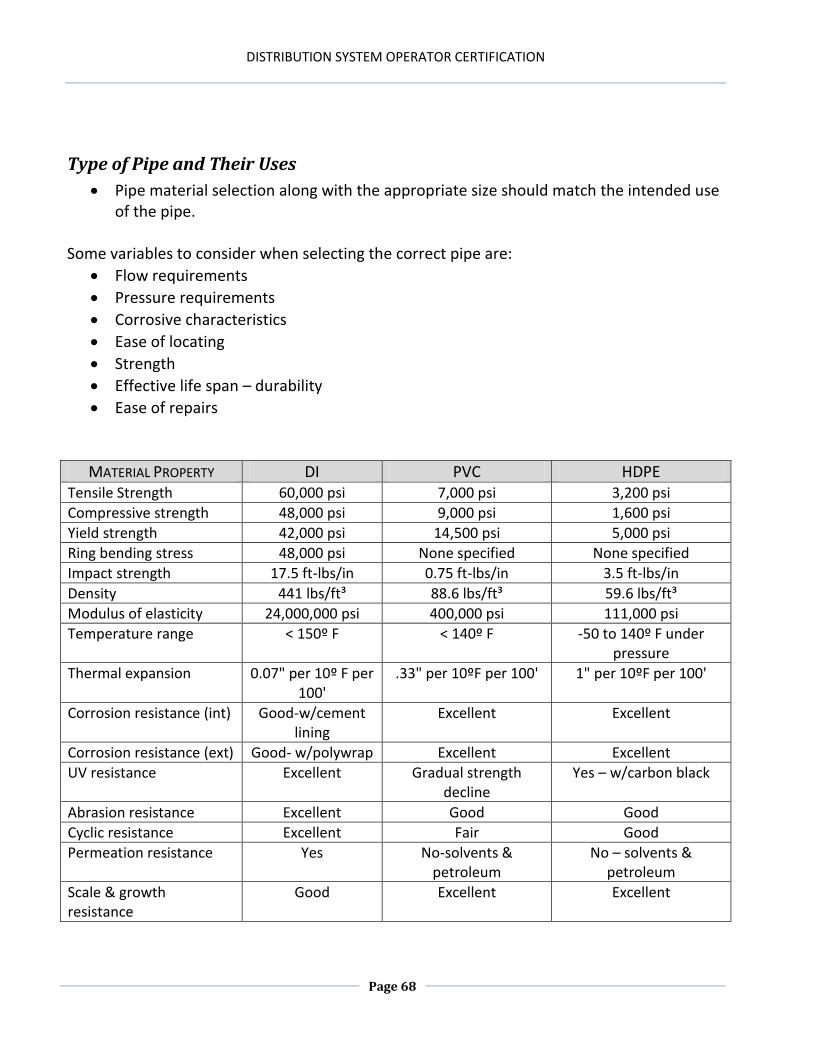
Type of Pipe and Their Uses
Pipe material selection along with the appropriate size should match the intended use of the pipe.
Some variables to consider when selecting the correct pipe are:
Flow requirements
Pressure requirements
Corrosive characteristics
Ease of locating
Strength
Effective life span – durability
Ease of repairs
MATERIAL PROPERTY DI PVC HDPE Tensile Strength 60,000 psi 7,000 psi 3,200 psi
Detailed plans of the project should be prepared by the project engineer in conjunction with input of the distribution operators. Planning for future growth and development will save money in the future. These plans should include grade, depth, alignment and soil type specifications. Plans must be submitted to the appropriate agencies for approval before construction begins. Right of way and access issues should be resolved before beginning construction. Familiarizing your work plans with other utilities in the area (phone, gas, cable, etc.) will aid in reduced problems once construction begins. Reduce your liability by always having utility lines marked before construction begins. In Kentucky the number to call for line marking is 811.
Data Requirements for a Detailed Management Plan
PHYSICAL Exist New PERFORMANCE Exist New COMMERCIAL/ SERVICE Exist New
Installation/yr Y Y Complaint frequency
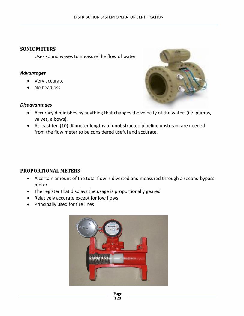
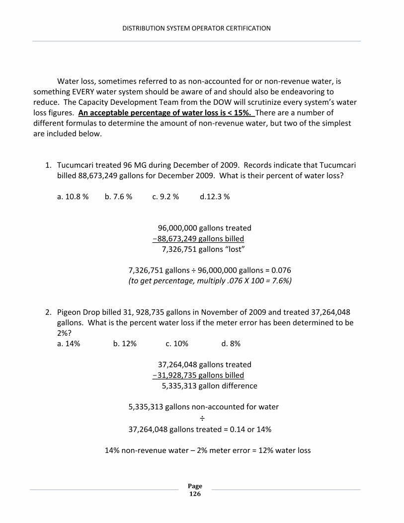
A Y Critical customer
Y Y
Diameter Y Y Type of complaint A Y Affect on Community
Y Y
Material Y Y Break frequency A Y No. of People Served
A A
Length Y Y Type of break A Y Length of shutdown
A A
Location Y Y Reason for break A Y Coordination w/others
A A
Interior lining A Y Service (hydraulic) adequacy
Y Y
Exterior protection
A Y Fire Flow Adequacy Y Y
Joint A Y
Wall thickness
A Y
Soil conditions
A A
Internal condition
A
External condition
A
Y = yes, in all cases A = as needed, or as available
DISTRIBUTION SYSTEM OPERATOR CERTIFICATION
Page 70
Pipe Installation
The proper installation of pipe will minimize maintenance problems and aid in desirable water quality and therefore, public health. Improper installation can result in water loss, water quality degradation, and loss of service, loss of consumer confidence, water leaks and increased monetary demands.
OPERATIONAL/PHYSICAL Applies to Options CHEMICAL Applies to Options
Manufacturing defects M,P,C No Internal corrosion M,C Yes
Improper design/installation
M,P,C No External corrosion-soil M,C Yes
Geologic instability M,P,C No External corrosion-other
M,C Yes
Higher operating pressures M,P,C Yes Leadite corrosion M Yes
Hydraulic transients M,P,C Yes Leadite expansion M Yes
Changes in water temp M Yes Material incompatibilities
M Yes
Excessive external loads M,P,C No Gasket deterioration M,P,C Yes
Damage from digging M,P,C No Material fatigue P No
M = Metallic (ductile iron and/or cast iron) P = (PVC or HDPE) C = Concrete (RCP or PCCP)
Comparison of Distribution-Size Pipe Materials – Operational Concerns
OPERATIONAL CONCERN DI PVC HDPE Ease of installation subjective subjective subjective
Can be direct tapped yes yes no
Need for special installation equipment no no yes
Need for special bedding for typical installations
no yes no
Need for joint restraint yes yes no
Ability to locate underground excellent poor – needs tracer wire
poor – needs tracer wire
Applicable for above-ground installations yes yes, with UV protection
yes
Applicable for aqueous installations yes yes Yes-potential for flattening
is high
Anticipated service life 100 years 50-100 years 50 years
DISTRIBUTION SYSTEM OPERATOR CERTIFICATION
Page 71
(12) Maps (a) Within twelve months of November 15, 1990, public and semipublic water systems shall have on the premises, or conveniently located to the premises, and an up-to-date map of the distribution system. The map shall, at a minimum, show: 1. Line size 2. Cutoff valves 3. Fire hydrants 4. Flush hydrants 5. Tanks 6. Booster pumps 7. Chlorination stations 8. Connection to emergency or alternative sources 9. Wholesale customer master meters; and 10. Type of piping material in the distribution system and its location (b) If a public water system, due to age, improper documentation, lost documentation or other valid reason is not able to comply with this requirement, the system may petition the cabinet to modify this requirement to the extent that compliance is not feasible. The petition for modification shall state specifically what portion of this requirement is not practical and why.
(401 KAR 8:020)
Distribution system maps
All systems are required by regulation to have up to date maps of their distribution systems. Certain items are required to be listed on your map.
Public and semipublic water supplies – general provisions:
DISTRIBUTION SYSTEM OPERATOR CERTIFICATION
Page 72
When designing a distribution system, the elimination of dead-end lines is very important. Dead-ends promote the degradation of water quality and reduced or nonexistent chlorine residual.
TREE (BRANCHING) SYSTEM with DEAD ENDS LOOP SYSTEM
GRID SYSTEM
Obviously, the grid system is superior
to the tree system as water is always moving and replenishing itself. The elimination of dead end lines or the frequent or routine flushing of them should be a priority. There are many types of flushing devices available for this purpose, from homemade to solar powered.
DISTRIBUTION SYSTEM OPERATOR CERTIFICATION
Page 73
Excavation
Many factors dictate the depth and width of a trench excavation. Economics, pipe size, available equipment, location of excavation, climatic conditions, pipe load, soil characteristics and groundwater conditions have an impact on the size of your trench.
Open cut excavations include clean up that can turn into an expensive endeavor. The trench should be as shallow and narrow as is practical. The trench depth must satisfy the need to prevent freezing in cold weather (3 - 4 feet). If sufficient depth is not obtainable, the pipe should be insulated. The proper bedding material should be used to surround the pipe, particularly in rock trenches to prevent the pipe movement on the rock and causing leaks. Generally, the trench width should be no more than 1 to 2 feet greater than the pipe diameter.
Trench Safety
OSHA regulations should be followed to prevent injury or death whenever an excavation is undertaken. Spoil piles must be kept a minimum of two feet from the edge of a trench so as not to increase the weight on a trench wall and increase the likelihood of a trench collapse or cave-in. Ladders for entry and exit must be placed no more than 25 feet apart so workers can safely enter and leave the trench.
DISTRIBUTION SYSTEM OPERATOR CERTIFICATION
Page 74
Wherever possible, trenches should be stepped or sloped (grade of slope dependent upon soil type) to cut down on the likelihood of a cave-in.
DISTRIBUTION SYSTEM OPERATOR CERTIFICATION
Page 75
If sloping is not possible, shoring or trench boxes should be used to protect the
employees installing or repairing the pipe.
DISTRIBUTION SYSTEM OPERATOR CERTIFICATION
Page 76
Bedding
This is usually considered to be the material in which the pipe is partially or fully embedded. It increases the load bearing capability of the pipe. The trench bottom should be correctly leveled and compacted to ensure continuous, firm support throughout its length. The bedding material should be well graded material, uniform in size and not containing rocks or other materials that cannot be graded uniformly.
DISTRIBUTION SYSTEM OPERATOR CERTIFICATION
Page 77
Pipe Laying
Water mains should not be placed in the same trench with sewer lines. If the sewer pipe is leaking, as they often do, a water main could be surrounded by contaminated soil. If a break were to ensue in that water main, a serious health hazard could be in the making. Waterlines should be laid at least 2 feet above and 2 feet laterally from the sewer line. If the water and sewer lines are at the same elevation, they should be at least 10 feet apart. Whenever a water line crosses a sewer line, the water line must be at least 3 feet above the sewer line and should not contain any pipe joints, except pressure joints on either side of the pipe crossing.
When pipelines are installed under roads, railroads, etc., the pipe should be installed in a way that allows for the accessible repair or replacement of that pipe. Casing or casement pipe is required to protect the water line from loads and stress.
Thrust Blocking
Water under pressure and in motion can exert tremendous forces inside a pipeline. The forces can appear as water hammer, and strains on every fitting and appurtenance associated with the distribution system. A bend, tee, plug, hydrant, valve or any other fitting that changes the direction or velocity of water should be blocked or restrained in some manner. Thrust blocks are masses of concrete that are cast in place between the fitting that needs to be restrained and the undisturbed soil in the trench.
For example: If the water in a completely full 12 inch pipe that is 500 feet in length is
required to stop or change direction, there is over 24,485 lbs of water moving in the pipe.
(.785 x 1' x 1' x 500' x 7.48 gallons x 8.34 lbs.)
DISTRIBUTION SYSTEM OPERATOR CERTIFICATION
Page 78
***Do NOT cover the entire pipe or fitting with concrete as this will lead to extra hours of labor if the fitting requires maintenance.***
DISTRIBUTION SYSTEM OPERATOR CERTIFICATION
Page 79
Recent technological developments such as thrust restraints, hydrant restraints, pipe restraint rings, etc., can aid as an addition to thrust blocking or sometimes an alternative, particularly where the soil is disturbed or cannot be tamped at the time of excavation.
Backfilling
The purpose of backfilling is to provide support for the pipe, provide lateral stability between the pipe and the trench walls and to form a cushion around the pipe to protect it from potential damage. The backfill material should be clean and dry and small enough to fill voids and effectively protect the pipe. The material should contain enough material to be compacted properly to viably protect the pipe. Larger rocks, debris and frozen material should not be used to backfill. Fill the trench in stages and compact as each layer is installed. Tamping can be achieved by hand, mechanically or by saturation.
Pressure and Leak Testing
Testing for leaks and pressure should be accomplished before finish grading is done. The standard for pressure testing is 1.5 times the pipe’s normal working pressure or 150 psi, whichever is greater, and held for a minimum of 24 hours. If your pipe is installed by an outside contractor, this testing before they leave can alleviate a great deal of exasperating and expensive work just to put the pipeline in service.
DISTRIBUTION SYSTEM OPERATOR CERTIFICATION
Page 80
Tapping
Tapping, by definition, is the cutting in of threads on the inside of a drilled or cut hole. In the water business, tapping is the connecting of one water line to another.
Many utilities now use saddles for tapping because of the widespread use of plastic pipe. Connections can be made either when the main is empty (dry tap) or when the pipe is full and under pressure (wet tap). Fortunately, most tapping done today is wet tapping. This method is preferred because it lessens the risk of contamination and allows the connection to be made to the customer without service interruption to other customers.
The fitting used to connect small diameter service lines to water mains is called a
corporation stop. It is usually a brass ball valve that is threaded on both ends and screwed directly into a water main or a tapping saddle.
DISTRIBUTION SYSTEM OPERATOR CERTIFICATION
Page 81
Larger taps are made by shutting off the main and installing a tee fitting or by tapping into an existing water main. The larger taps require more expensive tapping machines, as well as operational expertise, and many utilities farm them out to contractors.
Flushing and Cleaning
The flushing of water lines is absolutely necessary to maintain water quality in distribution systems. Flushing will generally occur for one of three purposes: 1) To flush out debris or chlorinated water from newly installed or repaired lines. After installation or repair of a water line, flush and pressure test, disinfect, dechlorinate and flush again before returning or putting the water line into service. 2) To address localized problems such as taste, odor, color or coliform contamination. When customer complaints or contamination monitoring necessitate a reactive form of flushing. Reactionary flushing means that the problem exists before any corrective actions are taken. 3) To systematically and routinely clean the distribution system piping. Planned, engineered, systematic flushing can achieve a degree of cleaning the distribution system dependent upon the condition of the pipes and the viability of your flushing program. This type of flushing is proactive and preventative and can, if done correctly, scour your distribution piping. Velocities must be a minimum of 2.5 feet per second (fps) with 5-6 fps being the optimum velocities necessary to fully flush your distribution system. Proactive unidirectional flushing will reduce customer complaints, improve water quality and prolong the life of your distribution system.
DISTRIBUTION SYSTEM OPERATOR CERTIFICATION
Page 82
THE “OLD” WAY
UNIDIRECTIONAL
DISTRIBUTION SYSTEM OPERATOR CERTIFICATION
Page 83
Mechanical cleaning could be necessary if tuberculation deposits are prolific or if biofilms, iron bacteria, or slime growths abound in large quantities. Try flushing initially, but if this proves inadequate, it may become necessary to use mechanical devices such as pigs or scrapers, to sufficiently clean the line. In addition to cleaning the lines, an increase in the carrying capacity of the lines will reduce pumping and energy costs as well as increase operating pressures close to where they were when the main was installed.
Cleaning can restore lines to close to their original viability but frequently this is a temporary reprieve from the problems associated with old or neglected mains. A change in water chemistry or the additions of corrosion inhibitors are necessary to prevent a reoccurrence of tuberculation problems.
A line replacement program should be planned for and implemented. These programs call for the replacement of a certain percentage or dollar amount of distribution system piping annually. This will also prevent the overall deterioration of the distribution system and spread the cost of replacement over a longer period of time than having to replace a line suddenly due to its failure.
In the United States, the average pipe age ranges from 21 – 91 years. The current replacement rate in the US is only 0.5% annually. Some of the oldest sections of pipe are over 125 years old. Distribution piping will not last indefinitely and water quality is usually adversely affected by the condition of these older pipes.
PIPE DIAMETER CROSS-SECTIONAL AREA
(SQUARE FEET) GPM @ 2.5 FPS GPM @ 5 FPS
2” 0.022 25 50
4” 0.087 98 196
6” 0.196 220 440
8” 0.348 390 780
10” 0.545 612 1224
12” 0.785 881 1762
16” 1.395 1565 3130
18” 1.766 1981 3962
24” 3.14 3523 7046
30” 4.91 5505 11010
36” 7.065 8078 16156
DISTRIBUTION SYSTEM OPERATOR CERTIFICATION
Page 84
Biofilms
A thin layer of cells of a microorganism such as bacterium or fungus held to the surface of pipes by a material these microorganisms produce. These entities also produce and surround themselves with a gelatinous substance which makes them resistant to biocides. The most effective and cost-effective way to remove biofilms is flushing with velocities in the 5 fps range.
Factors Causing Biofilm Growth
Presence of microbial nutrients in the water
Characteristics of pipe walls, such as roughness or “C” factor
Microbial and chemical quality of the water entering the distribution system
Water temperature and pH
Low chlorine levels in the water
Velocity of the water
Characteristics of Biofilms
Form on surfaces in aquatic systems
“Resistant” to biocides
Composed of organic and inorganic substances
Monitoring is difficult Release organisms into bulk fluid (in our case, water)
1) Pipe Bursting – a method where the existing pipe is “split apart” and left in the ground and the new pipe is pulled into place right behind the head that splits or bursts the existing pipe. HDPE pipe or a special type of PVC is butt welded or fused together to allow for the long pipe runs. A pipe larger than the original pipe can be pulled into place. Runs of 1500 feet or more are possible with this method. 2) Slip Lining – a method whereby a replacement pipe is pulled into an existing pipe. This method is bound by the size of the existing pipe. Again, runs of 1500 feet are not uncommon.
DISTRIBUTION SYSTEM OPERATOR CERTIFICATION
Page 86
3) Pigging and/or mechanical cleaning – a mechanical means of removing mild tuberculation, scaling or biofilms from an existing pipe. Pigs are run through the existing lines by water pressure or mechanical scraper blades or rods are pulled through the existing pipe to clean it. 4) Pipe Jacking or microtunneling – a technique for installing underground pipes where hydraulic jacks are used with specially designed pipe behind a shield at the same time as excavation is taking place within the shield. Water is added at the point of excavation to form“slurry” to soften the ground for the excavating and recycled through lines to be separated in the slurry separation tank and reused for excavating.
pigs
DISTRIBUTION SYSTEM OPERATOR CERTIFICATION
Page 87
6) Cured in Place Sliplining - a method whereby a liner is pushed or pulled through an existing pipe and “cured” or heated with steam, hot air, hot water, or UV light and relines the existing pipe. The pipe is usually folded and allowed to unfold or sometimes forced to unfold by pumping air through them.
7) Cement lining – A high speed cement lining machine is pulled through an existing pipe followed by a trowel. The existing pipe is now relined with cement and its C- Factor returned to a high level. This method, since it relines an existing pipe, is bound by the size of the original pipe.
DISTRIBUTION SYSTEM OPERATOR CERTIFICATION
Page 88
8) Horizontal Directional Drilling – A machine that uses rods of varying lengths and diameters attached to a boring head. These rods can be directed to follow a predetermined route to follow the depth and routes desired and not disturb other utilities in the ground. Runs of 3000 feet are not uncommon. The original route is bored and then the product pipe is pulled back to the point of origin.
9) Moles - Pneumatically powered cylindrical tools laid in an excavated pit that bore a hole through rock and dirt toward a second excavated pit. Usually used for service connections.
There are more methods used for “trenchless” excavations, but these are among the most frequently used. With more and more utilities being laid underground, the viability of open cut trenching is getting harder all the time. One of these methods could be a favorable alternative to the traditional open- cut method of laying pipe and are extremely useful when attempting to rehabilitate a pipeline.
DISTRIBUTION SYSTEM OPERATOR CERTIFICATION
Page 89
Leak Detection
Leak detection programs are a necessary task in a distribution system. The costs of treating water and never receiving any income from the water is foolish. Leak rates should not exceed 15%. All services should be metered and accounted for each month. Leak Detection Methods LISTEN
1. Pick valves that are suspected to be in the general area of your leak 2. Follow the directional flow of the water 3. Pick two valves in series and shut the second valve (#2) off and then go back to the
first valve (#1) and shut if off. Wait ten minutes. 4. 4) Crack open valve #1 and put the valve wrench on the valve and listen. 5. 5) Since water under pressure moving through a small space makes a whistling or
screeching sound. If there is no sound or if the sound suddenly stops then there is no leak between those valves.
6. 6) If the noise continues then the water is going somewhere, probably from your leak
Hydrant Pressure 1) Remove the hydrant cap and slowly flush line to remove any sediment. 2) Replace cap with a cap containing a pressure gauge. 3) Secure all hydrant caps and charge the hydrant. 4) Read the line pressure. 5) Slowly close the two valves on either side of the hydrant starting with the downstream
valve (#2). 6) If both valves are tightly closed then the line pressure should hold. 7) If the pressure drops off quickly, water is leaving the main somewhere.
DISTRIBUTION SYSTEM OPERATOR CERTIFICATION
Page 90
Permanent meter setting. (particularly viable on stream crossing, railroads, etc.)
1) Install a tap on both the upstream and downstream side of the valve on stream crossings, railroads, etc.
2) Install a meter between the two taps 3) If water is moving through the meter, a leak is present.
DETECTION DEVICES Geophones – consist of two specially designed heavy brass plates connected to earpieces that resemble a doctor’s stethoscope. Portable electronic leak detectors – these use electronic sound amplification and go from basic models with just an on/off switch to ones that can tune out background noise.
DISTRIBUTION SYSTEM OPERATOR CERTIFICATION
Page 91
Leak correlators – based on sound amplification, with a twist. A pair of small portable amplification and transmitting devices , usually magnetic, are placed in contact with a meter, valve, hydrant, exposed main etc., and spaced at varying distances dependent on the composition of the line. The signal from each device is transmitted to the correlator. If line size, location of the line and pipe material is known the correlator screen can show where the leak is located. Usually within three feet or so.
DISTRIBUTION SYSTEM OPERATOR CERTIFICATION
Page 92
Chapter 6 Review
1. List three methods of trenchless technologies.
2. Unaccounted for water should be at or less.
3. Anytime water changes directions or stops, what should be added to the pipeline?
4. are microorganisms that attach themselves to pipe walls.
5. flushing is an engineered, more viable form of flushing.
1. Describe the functions as well as the strengths and shortcomings related to the different types of valves (gate, butterfly, globe, plug, ball, air/vacuum release, pressure reducing, altitude, and check).
2. Explain the importance and purpose of a valve maintenance program.
DISTRIBUTION SYSTEM OPERATOR CERTIFICATION
Page 96
Gate Valves
Operated in a fully open or fully closed position only
Used for isolating a part of the distribution system or a piece of equipment (i.e. fire hydrant, pump etc.)
NOT used for throttling
Very low headloss and turbulence in the fully open position
Not the best choice if needed to operate frequently
Thrust blocking and/or mechanical restraint must be used if installed at a dead end or water direction change
Maintained by exercising a full cycle operation on a regular schedule – at least annually
Valve card notations – number of turns, direction of open, location, type, size, date of installation and maintenance, inspection and/or repair.
DISTRIBUTION SYSTEM OPERATOR CERTIFICATION
Page 97
Leakage repair – O-rings, seals, gaskets, or mechanical joint gaskets
Butterfly Valves
Primarily used for isolation, but can be used for throttling or even as a check valve.
Wears better than gate valves
Shorter, lighter, and cheaper than gate valves in most cases
Higher headloss than gate valve and prevents the relining or mechanical cleaning of pipes.
Install in a closed condition
Minimal maintenance requirements, but removal is necessary for repair
DISTRIBUTION SYSTEM OPERATOR CERTIFICATION
Page 98
Globe Valves
An extremely versatile valve
Used primarily for pressure
Highest headloss of all valves operating in a fully open position
Can be used to control pressure, throttling (flow or altitude) and also isolation in small flow or line size applications
Design aids in disc wear so maintenance is seldom necessary, but removal is compulsory for repair.
Design also excludes mechanical pipe cleaning or relining without valve removal
DISTRIBUTION SYSTEM OPERATOR CERTIFICATION
Page 99
Plug Valves
Used for isolation where frequent operation is required
Not recommended for throttling unless especially designed as such
Design minimizes closing surge and allows for longer valve life than a gate valve
Generally heavier and more expensive than a gate valve
Low headloss, dependable, easy operation
DISTRIBUTION SYSTEM OPERATOR CERTIFICATION
Page 100
Ball Valves
Really an improved version of the plug valve
Same characteristics as a plug valve except much lower turning torque required and no metal to metal contact, which extends the life of the valve
We primarily use these in our service applications (corporation stop)
DISTRIBUTION SYSTEM OPERATOR CERTIFICATION
Page 101
Air/Vacuum Release Valves
Air release valves allow the removal of air from water lines due to turbulence or temperature variances which could collect and act as a partially or fully closed valve.
Vacuum release valves relieve the occurrence of negative pressure due to vacuum conditions that could collapse our pipes.
Vacuum release valves allow air to enter the pipeline while draining.
Both air and vacuum relief valves should be installed at high points in the distribution system and atop the mains.
DISTRIBUTION SYSTEM OPERATOR CERTIFICATION
Page 102
(They may be installed as combination valves or singularly in tandem.)
Pressure Reducing Valves
Usually globe type valves with a spring loaded diaphragm
PRV’s automatically maintain constant outlet pressure regardless of changes in the flow rate or upstream pressure.
These valves will hold a partially open position in response to the settings of the spring-loaded diaphragm.
Pressure reducing valves will throttle in this open position relative to the balance of opposing forces.
The use of two pressure reducing valves in sequence can be used to handle a wide range of flow rates.
DISTRIBUTION SYSTEM OPERATOR CERTIFICATION
Page 103
Altitude Valves
Controls tank levels below the hydraulic grade line Four types: 1. Double Acting – closes when the level in the tank reaches high water level; opens for
return flow out when line pressure falls below static reservoir head
2. Double Acting with Differential Control – works like double acting valve, except it can be set to activate under preset pressure parameters
3. Single Acting – water discharges from the tank through a separate line. Valve actuates to refill tank when the water level falls 4 – 6 inches below the high water level.
4. Single Acting with Differential Control – works similarly to a single acting, except the valve actuation level can be preset anywhere from 1 – 15 feet.
DISTRIBUTION SYSTEM OPERATOR CERTIFICATION
Page 104
Check Valves
Prevent the reverse flow of water or prevent the water from traveling in an unintended direction
Many controls are available to actuate the valve, such as swing gate (illustrated above) or spring loaded (illustrated below).
Used to maintain head pressure on the effluent side of a pump or maintain the integrity of some meters
DISTRIBUTION SYSTEM OPERATOR CERTIFICATION
Page 105
Valves should be exercised at least annually. An example of a valve maintenance form is included below.
Valve Maintenance Report or Log Examples:
VALVE RECORD XYZ Waterworks Valve No. ________
Location _________________________
___ ft _____ of _____ property line of _______
&___ft _____ of _____ property line of _______
Size _____ Make ____________ Type _______
Gearing _____________ By-pass____________
Opens ____________ Turns to Operate _____
Set in ___________ Depth to nut ___________
Remarks: ________________________________
MAINTENANCE & INSPECTION RECORD
DATE WORK DONE OK ? BY
(3 X 5 or 5 X 7 card)
Valve Maintenance Card
VALVE MAINTENANCE REPORT
XYZ Waterworks Valve No. ________
LOCATION _____________________________
MEASUREMENTS: CHECKED OK ________
Measured As Follows
_____ FT ______ OF _____ P.L. of __________
_____ FT ______ OF _____ P.L. of __________
VALVE TURNS ___________ TO OPEN
VALVE TURNS ___________ TO CLOSE
Packing: OK __Tightened __ Replaced __
Stem: OK ___Bent /Broken __Replaced __
Nut: OK ___ Missing ___ Replaced ___
Gears: Condition _______ Greased _______
Box ____ or Vault ____ OK __ Replaced ___
Buried ______ in. Protruding _____ in.
Riser too close to stem _____ Reset ____
Cover: Missing ___Broken __ Replaced ___
Wedged in ____ Tarred or Grouted In _____
Any Other Defects ______________________
Inspected _____________ By _____________
Defects Corrected ___________ By _______
DISTRIBUTION SYSTEM OPERATOR CERTIFICATION
Page 106
Chapter 7 Review
1. Explain the purposes of each type of valve and what application each is designed for.
2. Where more than one type of valve could be used in a particular application, why
would you choose the valve you do?
3. Which type of frequently used valves are much more maintenance intensive than the others?
4. What valve is used to attach water services to water mains?
5. Which valve can be adjusted?
DISTRIBUTION SYSTEM OPERATOR CERTIFICATION
Page 107
Answers for Chapter 7 Review 1. Gate – Isolation Butterfly – Isolation and throttling Globe – Throttling, pressure, altitude Plug – Frequent isolation Ball – Service connections
Air/vacuum – To release air from lines and to relieve vacuum conditions in a pipeline and to drain a pipeline.
PRVs – Maintain pressure Check valves – allows the movement of water in only one direction 2. Applicability 3. Butterflies 4. Corporation stop 5. PRV
DISTRIBUTION SYSTEM OPERATOR CERTIFICATION
Page 108
DISTRIBUTION SYSTEM OPERATOR CERTIFICATION
Page 109
Chapter 8: HYDRANTS
Chapter 8 Objectives
1. Differentiate between the two major types of hydrants (wet barrel and dry barrel). 2. Describe the hydrant components (bonnet, upper barrel, lower barrel, and shoe). 3. Describe the proper order of installation for a hydrant. 4. Identify the purpose of flushing. 5. Describe how to distinguish a fire hydrant from other types. 6. Identify the purpose of blow off hydrants. 7. Identify how to obtain flow measurements. 8. Describe proper maintenance procedures for hydrants.
DISTRIBUTION SYSTEM OPERATOR CERTIFICATION
Page 110
Two classifications of hydrants made in the United States are the wet barrel and the
dry barrel hydrant. Keep in mind that the MINIMUM SIZE LINE USED FOR A FIRE HYDRANT TO SATISFY FIRE FLOW AND PRESSURE REQUIREMENTS IS 6 INCHES.
Wet barrel hydrants contain the operating valve in the nozzle section of the hydrant.
Operated by rotating the operating stem on each of the outlets, with each discharge port being independently valved
Used in warm weather climates
Their main advantage is the ease in which a second fire truck can be connected
Not used in Kentucky because of variations in temperature.
Dry barrel hydrants have the operating valve installed below ground level.
These hydrants are equipped with special drain valves or weep holes that allow the above ground portion of the hydrant to automatically drain when the hydrant is not in use.
Used in colder climates where there is a likelihood of freezing temperatures.
If equipped with a traffic kit, the hydrant will not usually lose water if struck.
DISTRIBUTION SYSTEM OPERATOR CERTIFICATION
Page 111
***FIRE HYDRANTS SHOULD ALWAYS BE OPENED AND CLOSED SLOWLY.***
Hydrant Components
Bonnet
The top of the hydrant contains the bonnet. The bonnet protects the packing and the operating nut mechanism. Upper Barrel
The upper barrel contains the outlet nozzles and the “O” rings that prevent water from entering the bonnet of the hydrant. Common nozzle sizes include 2½ inch hose nozzles and usually four or six inch pumper nozzles. Lower Barrel
These sections determine the height or bury depth of the hydrant. The bury or bury depth is the distance from the bottom of the inlet connection to a point four inches below the flange that connects the lower barrel to the upper barrel.
DISTRIBUTION SYSTEM OPERATOR CERTIFICATION
Page 112
Shoe
The shoe is where the inlet connection is made. The shoe also changes the direction of the flow from horizontal to vertical. On most compression hydrants, the main valve assembly is located either in the shoe or directly on top of it. The size of the main valve is referred to as the main valve opening (MVO). This is the inside diameter of the valve seat and sizes that range from four through six inches are common. The shoe also contains the drain valve assembly and/or weep holes, used to drain the hydrant when it is closed.
DISTRIBUTION SYSTEM OPERATOR CERTIFICATION
Page 113
Proper installation order on a fire hydrant is main, gate valve, pipe, and thrust block. Fire hydrants should be inspected and maintained at least annually.
Compression Type Hydrants
In compression hydrants, the main valve moves jointly on a vertical axis against a seat located in the hydrant base. The valve moves against the seat to close and away from the seat to open. A vertical stem moves up or down when the operating nut is rotated. The valve may be located below the seat and opens against the pressure or above the seat and opens with the pressure.
Pitot Tubes, Diffusers, and Dechlorinators
Pitot tubes can be utilized in the distribution system to obtain flow measurements in gallons per minute and pressure (PSI) readings from fire hydrants.
DISTRIBUTION SYSTEM OPERATOR CERTIFICATION
Page 114
Diffusers redirect the flow from the hydrant and somewhat dissipate the force or intensity of the flow in order to reduce potential property damage and hazards to motorists during flushing. Some diffusers are equipped with pressure and flow gauges and some have dechlorinating capabilities.
Always dechlorinate the water when flushing. Chlorine flowing into streams will damage the ecosystem of that stream. Sodium thiosulfate is commonly used to remove chlorine from water. Chlorine levels should read 0.01 ppm at discharge.
Blow Offs
Blow off valves are used to drain lines, remove accumulated sediment via flushing and resolve customer complaints. Blow offs are used at dead ends where fire hydrants are not needed. All blow offs should be flushed regularly to maintain water quality.
DISTRIBUTION SYSTEM OPERATOR CERTIFICATION
Page 115
Chapter 8 Review
1. Hydrants should be exercised and lubricated on a(n) ___________ basis at a
minimum.
2. One component that can prevent the successful opening or closing of a hydrant is the _______.
3. Water released from hydrants and blow-offs needs to be, by regulation, ___________ before the water hits the ground.
4. What is located in the show of the hydrant that allows water to drain from the hydrant?
1. Identify the purpose of meters. 2. Describe issues to consider when choosing a meter. 3. Identify different types of meters and the advantages and disadvantages of each type. 4. Identify proper placement and installation techniques. 5. Describe the benefits of Automated Meter Reading. 6. Determine the amount of storage necessary to functionally operate a distribution
system. 7. Describe the suggested acceptable rate of water loss.
DISTRIBUTION SYSTEM OPERATOR CERTIFICATION
Page 118
Water Loss
The United States possesses a 34,000,000,000-gallon-a-day supply.
6,000,000,000 gallons of water per day is water loss or non-accounted for public use.
There are approximately 53,000 water systems in the United States.
The average water loss is 113,207,540 gallons per system.
At a rate of $3.00 per thousand gallons, the average revenue loss per system equates to $339,621 per system.
Because so many systems have ignored or under-maintained their distribution systems, these figures can only increase.
Purpose
1. To measure and display the amount of water passing through it.
2. To prevent wasted water by reducing consumption.
3. To enable accurate billing for the volume of water used by each customer
4. To measure the volume of water produced in relation to the volume of water used so water losses can be estimated and tracked.
When choosing a meter always take into account:
The ability to measure and register anticipated flow levels. The ability to meet required capacity with minimal headloss. The durability and ruggedness of the meter. Is that meter supplier a known and reputable manufacturer? Is the meter easy to maintain and repair? Is there a sufficient quantity of spare parts and competent technical services?
Types of Meters
Meters can usually be classified as small-flow meters, large-flow meters and combination large- and small-flow meters.
DISTRIBUTION SYSTEM OPERATOR CERTIFICATION
Page 119
SMALL-FLOW METERS
Displacement Type
Piston: Measures the number of times the chamber (of a known volume) is filled and emptied. A piston or disc goes through a particular cycle of motion, and its movement is transferred to a register either notated in gallons or cubic feet per second.
Advantages:
Measures wide variations of flow rates in preset parameters
Accurate at measuring low flows
Disadvantages:
Limited capacity (less accurate at greater sizes)
Corrosion, scale or other foreign matter will cause meter to under-register or stop
DISTRIBUTION SYSTEM OPERATOR CERTIFICATION
Page 120
NUTATING DISC
DISTRIBUTION SYSTEM OPERATOR CERTIFICATION
Page 121
VELOCITY METERS
Normally used for pumps with continuous high-flow rates, main transmission lines, irrigation, industrial and other high-flow applications. Available in sizes anywhere up to 36 inches and above. Most measure the velocity of flow past a known cross-sectional area.
Advantages
Handles high-flow rates without damage to working parts.
Rugged and easy to maintain Low headloss relative to high-flow rates
Disadvantages
Unreliable at low flows Mainly used for continuous high-flow applications, such as irrigation, industrial, large
golf courses and other high-flow applications
Venturi Meter Turbine Meter Propeller Meter
Propeller Meter Propeller Meter
Works on the Bernoulli Principle
DISTRIBUTION SYSTEM OPERATOR CERTIFICATION
Page 122
COMPOUND METERS
Used for accurate measurement of widely varied flows
Combines both the velocity and displacement meters into one unit
The amount of headloss controls which unit is being utilized during a given time
Advantages
Will measure a wide variance of flows from entities, such as hospitals, distilleries, factories, etc.
Disadvantages
Friction or headloss is higher than velocity meters
Accuracy is limited during changeover from one meter to the other Large, heavy, cumbersome and expensive
ELECTRONIC METERS
Measures a differential in electrical (magnetic) current passing through a cross-sectional area.
Low-flow
High-flow
DISTRIBUTION SYSTEM OPERATOR CERTIFICATION
Page 123
SONIC METERS
Uses sound waves to measure the flow of water
Advantages
Very accurate
No headloss
Disadvantages
Accuracy diminishes by anything that changes the velocity of the water. (i.e. pumps, valves, elbows).
At least ten (10) diameter lengths of unobstructed pipeline upstream are needed from the flow meter to be considered useful and accurate.
PROPORTIONAL METERS
A certain amount of the total flow is diverted and measured through a second bypass meter
The register that displays the usage is proportionally geared
Relatively accurate except for low flows Principally used for fire lines
DISTRIBUTION SYSTEM OPERATOR CERTIFICATION
Page 124
MAG METERS
A magnetic flow meter (mag flowmeter) is a volumetric flow meter that does not have any moving parts. The operation of a magnetic flowmeter is based upon Faraday’s Law, which states that the voltage induced across any conductor as it moves at right angles through a magnetic field is proportional to the velocity of that conductor. For obtaining viable measurements, there should be a length of straight pipe 2 times the diameter of the meter in front of the mag meter and a length of pipe equivalent to 1 times the diameter of the meter after the placement of the meter. Elbows within this range will negatively affect the accuracy of the flowmeters.
Faraday’s Formula: E is proportional to V X B X D where: E = voltage generated in a conductor V = velocity of the conductor B = magnetic field strength D = length of the conductor
DISTRIBUTION SYSTEM OPERATOR CERTIFICATION
Page 125
AMR (Automatic Meter Reading)
AMR’s is an improved method of recording water usage. The old fashioned way sends meter readers out every month to open every meter vault and record the volume used for that month has now become improved. AMR’s has changed how distribution systems record water usage. Benefits will be recognized by the utilities with increased efficiencies, outage detection, backflow detection, tamper notification and reduced labor cost as a result of automating reads, connections and disconnects.
Accuracy Requirements for New Metersa b
AWWA Standard Designation and Type of Meter At Normal Test Flow % At Minimum Test Flow %
C700 Displacement Type 98.5 – 101.5 95
C701 Turbine Type 98.0 – 102.0 Not Required
C702 Compound Typec 97.0 – 103.0 95
C703 Fire Service Typec 97.0 – 103.0 95
C704 Propeller Type 98.0 – 102.0 95 a. AWWA Standards b. There is no standard for the accuracy of repaired meters, but the practice at many utilities is to require the same accuracy as for new meters at the normal test flow and at least 90 percent at the minimum test flow. c. The accuracy during the “change over period,” which is defined in the applicable standards, shall not be less than 85 percent.
**Water meters should be installed behind the curb and protected in a meter vault.**
DISTRIBUTION SYSTEM OPERATOR CERTIFICATION
Page 126
Water loss, sometimes referred to as non-accounted for or non-revenue water, is something EVERY water system should be aware of and should also be endeavoring to reduce. The Capacity Development Team from the DOW will scrutinize every system’s water loss figures. An acceptable percentage of water loss is < 15%. There are a number of different formulas to determine the amount of non-revenue water, but two of the simplest are included below.
1. Tucumcari treated 96 MG during December of 2009. Records indicate that Tucumcari billed 88,673,249 gallons for December 2009. What is their percent of water loss?
7,326,751 gallons ÷ 96,000,000 gallons = 0.076 (to get percentage, multiply .076 X 100 = 7.6%)
2. Pigeon Drop billed 31, 928,735 gallons in November of 2009 and treated 37,264,048 gallons. What is the percent water loss if the meter error has been determined to be 2%? a. 14% b. 12% c. 10% d. 8%
14% non-revenue water – 2% meter error = 12% water loss
DISTRIBUTION SYSTEM OPERATOR CERTIFICATION
Page 127
Meter Installation Chart
Date Purchased____________ Brand _______________ Type _____________ Cost_______
Install Date
Min Flow
Int Flow
Max Flow
% accuracy before repair
% accuracy after repair
Cost of Repair Tested by
Remarks:
DISTRIBUTION SYSTEM OPERATOR CERTIFICATION
Page 128
Chapter 9 Review
1. Which meters have no moving parts? 2. What happens when you install an undersized meter in a supply line?
3. The two types of meters commonly used for residential services are the _____________________ and the _______________ ___________________.
4. When a meter has excessive wear, what will be the results in relation to registering flow?
5. Which meter has the lowest headloss?
6. If the city of Rays treated 117.8 MG of water during the month of May and their non-accounted water totaled 2,238,200 gallons, what is your water loss percentage?
DISTRIBUTION SYSTEM OPERATOR CERTIFICATION
Page 129
Answers for Chapter 9 Review 1. Venturi, Mag Meter 2. It under registers 3. Nutating disc and piston 4. Under registers 5. Venturi or Mag Meter 6. 2,238,200 = 1.9% 117,800,000
DISTRIBUTION SYSTEM OPERATOR CERTIFICATION
Page 130
DISTRIBUTION SYSTEM OPERATOR CERTIFICATION
Page 131
Chapter 10: BASIC HYDRAULICS
Chapter 10 Objectives
1. Identify major hydraulic concerns. 2. Demonstrate the ability to calculate flow (as functions of velocity and cross-sectional
area) in gpm from different size fire hydrant openings and pipes. 3. Differentiate between several concepts related to basic hydraulics (e.g., psi vs. head,
pressure vs. velocity, static vs. dynamic) and describe the major hydraulic concerns of a water distribution system.
4. Describe hydraulic grade line as it relates to pressure head and elevation head. 5. Explain and calculate “C” factor using Williams & Hazen’s formula while describing
equivalent flow, the rule of continuity, and pressure loss related to undersized piping. 6. Demonstrate the ability to determine appropriate line size and storage facility height
(pressure and head).
DISTRIBUTION SYSTEM OPERATOR CERTIFICATION
Page 132
The major hydraulic concerns of a water distribution system are
1. Will water flow? 2. In what direction? 3. With sufficient pressure?
In Kentucky, the minimum design pressure is 30 psi and the minimum working
pressure is 20 psi. When pressure falls below 20 psi, public notification is mandatory by regulation. Accomplishing these hydraulic goals can be a difficult task, especially in terrain that includes substantial changes in elevation, which are present in our state.
DISTRIBUTION SYSTEM OPERATOR CERTIFICATION
Page 133
Flow Rate Calculations
Q = A X V Q = FLOW expressed as ft³/sec (cubic feet/second—sometimes presented as cfs) V = VELOCITY expressed as fps (feet per second) A = CROSS-SECTIONAL AREA expressed as ft²
Flow is volume/time. Can be expressed as:
gallons per minute (gpm)
million gallons a day (MGD)
Velocity is speed or time/distance. Can be expressed as:
feet per second (fps)
yards per hour
blocks per day
Area is a two-dimensional measurement. In this equation, we calculate the cross-
sectional area. All we are concerned with in this equation relative to area is a two-dimensional measurement.
Anytime you have a measurement notated in inches, we must convert it to feet in order for us to calculate a correct answer. All that is needed to convert inches to feet is to divide by 12, which is how many inches are contained in a foot. Here are some examples: 8 inches is .666 feet (8 inches ÷ 12 inches) 2 inches is .166 feet (2 inches ÷ 12 inches) 42 inches is 3.5 feet (42 inches ÷ 12 inches)
.785 X D (ft) X D (ft) for a circle
Length X Width for a rectangle
DISTRIBUTION SYSTEM OPERATOR CERTIFICATION
Page 134
Area Examples
1. What is the cross-sectional area of a 16 inch pipe? The formula to obtain this is .785 X D (in feet) X D (in feet)
Area = .785 X (16 inches ÷ 12 inches) X (16 inches ÷ 12 inches)
Area = .785 X 1.33 ft X 1.33 ft Area = 1.4 ft² (actually 1.3885865 rounded up)
So, the cross-sectional area for a 16 inch pipe is 1.4 ft²
2. Water is flowing through a 4 foot long by 2 feet wide by 3 feet deep trench at 1.9 feet per second. What is the flow?
Q = A X V Q (flow) expressed as ft³/sec = (4 ft X 2 ft) X 1.9 fps
Q (flow) expressed as ft³/sec = 8 ft² X 1.9 fps
A = 15.2 ft³ (cubic feet per second)
Since we are figuring area (a two-dimensional measurement), we do not need to use the depth into the equation for the question above.
3. The flow through a 10 inch water line is 4.4 ft³/sec. What is the velocity of this water?
V = Q ÷ A V (velocity) expressed as feet per second (fps) = Q (flow) ft³/sec ÷ A (area) ft²
V = 4.4 ft³/sec (flow) ÷ (.785 X (10" ÷ 12") X (10" ÷ 12")) V = 4.4 ft³/sec ÷ (.785 X .83' (ft) X .83' (ft))
V = 4.4 ft³/sec ÷ .54 ft²
V = 8.1 fps (feet per second)
DISTRIBUTION SYSTEM OPERATOR CERTIFICATION
Page 135
4. The flow through a 22 inch pipe is 3142 gpm. What is the velocity?
V = Q ÷ A
In order to satisfy the equation, we have to convert 3142 gpm into ft³/sec
The conversion sheet shows that 1 ft³/sec = 448.8 gpm V = (3142 gpm ÷ 448.8 gpm) ÷ .785 X (22" ÷ 12") X (22" ÷ 12")
V = 7 ft³/sec ÷ (.785 X 1.83' X 1.83') V = 7 ft³/sec ÷ 2.6 ft²
V = 2.69 or 2.7 fps
Practice Examples
1. The flow through the 36 inch main transmission line in the community of Getz is 3.6
MGD. What is the velocity of the water through this pipeline?
2. Water is traveling through a 4 inch pipe at 0.7 fps. What is the flow in this pipe expressed as gpm?
3. You are preparing to attach a line extension to a 12 inch pipe when the track hoe operator punctures the existing line. It took 3 minutes for water to travel through the trench that was 4 feet deep, 3 feet wide and 200 feet long. What is the velocity of this water?
4. Water is flowing through a completely filled 24 inch water main at 75 feet per minute. What is the flow in this pipeline?
5. In order for your new pump to work efficiently it needs a minimum of 700 gpm to be pumped through it. The line attached to the pump is 18 inches, and the water is flowing at 1.1 fps. How many gallons per minute are moving through the new pump?
DISTRIBUTION SYSTEM OPERATOR CERTIFICATION
Page 136
Solutions
1) V = Q ÷ A V = (3.6 MGD X 1.55 ft³/sec) ÷ .785 X (36" ÷ 12") X (36" ÷ 12") V = 5.58 ft³ ÷ (.785 X 3' X 3') V = 5.58 ft³/sec ÷ 7.07 ft² V = 0.8 (actually 0.789) fps 2) Q = A X V Q = .785 X (4" ÷ 12") X (4" ÷ 12") X 0.7 fps Q = (.785 X .33' X .33') X 0.7 fps Q = 0.085 ft² X 0.7 fps Q = .0595 ft³/sec How many gallons per minute would that be? 26.7 gpm 3) If it takes 3 minutes (180 seconds) for the water to travel 200 feet, then we could say
that the water was traveling at a rate of 1.1 fps (200 feet ÷ 180 seconds).
4) Q = A X V Q = (.785 X 2' X 2') X 1.25 fps which has been converted from 75 feet per minute Q = 3.14 ft² X 1.25 fps Q = 3.9 ft³/sec 5) Q = A X V Q = (.785 X (18" ÷ 12") X (18" ÷ 12")) X 1.1 fps Q = .785 X 1.5' X 1.5' X 1.1 fps Q = 1.94 ft³/sec Q= Converting to gpm 1.94 ft³/sec X 448.8 gpm = 870.6 gpm Q = 870.6 gpm
DISTRIBUTION SYSTEM OPERATOR CERTIFICATION
Page 137
Hydraulics
Hydraulics is the branch of engineering that focuses on the practical problems of collecting, storing, measuring, transporting, controlling and using water or other liquids. Liquids in motion produce forces and pressure whenever the velocity, flow direction or elevation changes. Knowing pipe pressure and flow along certain points in our distribution systems can help determine the proper pipe size and sufficient capacity. These parameters can also help determine what pipe material would work best in certain situations. In addition, having an understanding of hydraulics can help systems determine if pressure reducers or pumps are necessary to transport water in an efficient manner. Also, basic understandings of hydraulics can save money, improve water quality, ensure regulatory compliance and help determine the cost and viability of distribution system improvements.
Some of the operational concerns than confront the successful delivery of our water are elevational changes in the topography (elevational head), energy lost through the transmission of the water through the pipelines (frictional head), (velocity head) and pressure requirements that have to be maintained to ensure water quality and regulatory compliance. Understanding that water has a unit weight is important. Water has a unit weight of 8.34 lbs per gallon or 62.4 lbs/ft³.
1 cubic foot of water (1 ft X 1 ft X 1 ft) weighs 62.4 lbs.
DISTRIBUTION SYSTEM OPERATOR CERTIFICATION
Page 138
If it rests on 1 square foot or 144 square inches, then it exerts 0.433 pounds per square inch. (psi). Pressure is derived by the formula as Force/Area.
Therefore, one square foot of water exerts 0.433 psi.
Now consider 10 feet of water. 10 cubic feet of water weighs 624 lbs if it rests on 1 square foot or 144 square inches.
To determine pressure (psi) in relation to a column of water, use “H” (height) in feet of water. If a standpipe held 80 feet of water and the pressure gauge was at the base of the tank, then
Pressure (psi) = Height of water column X 0.433 psi Pressure = 80 ft of water X 0.433 psi
Pressure = 34.64 psi
Water exerts force and pressure when it is confined in any type of structure. In our business, the types of structures we commonly use are pipes and tanks.
P = F
= 62.4 lbs.
= 0.433 PSI A 144 sq. in.
P = F
= 62.4 lbs./ft³ x 10 ft³
= 4.33 PSI A 144 sq. in.
DISTRIBUTION SYSTEM OPERATOR CERTIFICATION
Page 139
There is a difference between force and pressure. Pressure is defined as force per unit area, commonly expressed as pounds per square inch (lb/in² or psi).
The pressure at point A equals the pressure at point E, since these points are the depth in the water. Likewise, the hydrostatic pressure at points B, C, and D are equivalent.
Hydrostatic Pressure
The pressure water exerts is called hydrostatic pressure. These principles always apply to hydrostatic pressure. 1. Pressure depends only on the depth of water above the point in question (not on the
water surface area). 2. Pressure increases in direct proportion to the depth of water. 3. Pressure in a continuous volume of water is the same at all points that are at the same
depth or elevation. 4. Pressure at any point in the water acts in all directions at the same magnitude.
Pressure also exists at the surface of the water because of the weight of the air above.
A E
water surface
zero gauge pressure
connecting pipe
B C D
B C D
DISTRIBUTION SYSTEM OPERATOR CERTIFICATION
Page 140
This pressure is called atmospheric or barometric pressure. Atmospheric pressure at sea level is 14.7 psi. In practical applications for the distribution operator, atmospheric pressure is NOT used for hydraulic calculations and is considered to be a zero reference or starting point. The application that uses atmospheric pressure is called absolute pressure, as opposed to gauge pressure.
Here we have two storage tanks side by side with different volumes. Even though these tanks have differing volumes, the pressure is the same because the column of water in each tank is the same. Hydrostatic pressure depends solely on the height of water above given points and NOT on the volume of water. In this above illustration, the pressure at the base of each tank is 21.65 psi. (50 feet X .433 psi) If whatever pressure gauge we used included atmospheric pressure (psia), they would NOT read the same.
50 feet 50 feet
36.35 psi 21.65 psi + 14.7 psi psig
21.65 psi
DISTRIBUTION SYSTEM OPERATOR CERTIFICATION
Page 141
Example 1 A small water system has an elevated water storage tank and connecting ductile iron
pipeline as shown in the illustration above. Calculate the hydrostatic pressure at points A, B, C, D. A. 2000 feet – 1950 feet = 50 feet elevational difference. 50 ft X 0.433 psi = 21.65 psi
B. The total depth of the water at point B is 2000 feet – 1900 feet = 100 ft 100 feet X 0.433 psi = 43 psi or lbs/in²
C. The pressure at point C is the same as point B because there is no elevational difference.
D. The total depth of the water above point D is 2000 feet – 1600 feet = 400 feet 400 feet X 0.433 psi = 173.2 psi or lbs/in²
closed valve
ground surface
water main
elevation 1900 feet point C
elevation 1900 feet point B
elevation 2000 feet – maximum water height
elevation 1950 feet – bottom of water in elevated tank
elevation 1600 feet point D
Point A
DISTRIBUTION SYSTEM OPERATOR CERTIFICATION
Page 142
Example 2
Another issue that is becoming more commonplace is providing a water service for a customer with a house at the top of a hill. In this example, a 6-inch main provides the line to be tapped for the service line. The pressure at the water meter is 51 psi. The house sits on a hill and through topographic maps it is determined the meter is at an elevation of 325 feet and the house is at an elevation of 405 feet.
Calculate the pressure drop from the meter to the house.
325 feet – 405 feet = - 80 feet - 80 feet X 0.433 = - 34.64 psi 51 psi – 34.64 psi = 15.36 psi Let’s take this a step further. This house has a bathroom on the second floor.
Estimate another 10 feet of elevation to the second floor. So, there is an additional 10 feet of elevation, which will result in an additional 4.33 psi pressure drop up to the second floor bathroom.
If we add the additional 4.33 psi to the original 34.64 psi, we now have a pressure
drop of 38.97 or 39 psi. Our starting measurement of 51 psi – 39 psi (pressure drop) means that the water in
the second floor bathroom would be measured at approximately 12 psi.
In the above example, it would most likely be wise to inform the customer that the water pressure in their house will be low. ALSO, explain to the customer that THEY can INSTALL and MAINTAIN a small booster pump to increase pressure. This is done at THEIR expense, not the utility’s expense.
DISTRIBUTION SYSTEM OPERATOR CERTIFICATION
Page 143
Example 3
The inverse of this situation could very well arise. A customer has a house in a valley with an elevation 156 feet below the connecting point at the transmission main. The pressure at the top of the hill is 94 psi.
What would the pressure be at the service connection entrance to the house? P (pressure) = 0.433 X Height P = 0.433 X 156 ft P = 67.55 psi Pressure reading at the top of the hill 94 psi + additional pressure gained by elevation
gained equals 67.55 psi. 94 psi + 67.55 psi = 161.55 psi at the service entrance to the house. It is sometimes more convenient to express pressure in terms of the height of a
column of water in feet. This is called pressure or elevational head and is the actual or equivalent height of water above the point in question.
For example, when evaluating a water distribution system to determine how high the pressure will push the water up a hill. By turning the equation around, we get: H = P ÷ 0.433 or by using your conversion sheet, which dictates that every 1 psi is equivalent to 2.31 ft of head. (The 2.31 comes from dividing 1 by 0.433, which gives you 2.309 or 2.31.)
So if we had to overcome a rise in elevation of 65 feet and our starting pressure at the main is 65 psi, then we could take 65 psi ÷ 0.433 psi, which equals 150.1 feet.
OR
Multiply the pressure in psi (65) X 2.31 ft of head, which equals 150.1 ft of head.
So theoretically, the water in the main could rise to a height of 150.1 feet, which is equivalent to 65 psi.
If we had to overcome a 65 foot rise in elevation and our starting pressure was 65 psi,
we could determine what the pressure would be at the crest or apex of the hill.
DISTRIBUTION SYSTEM OPERATOR CERTIFICATION
Page 144
Starting pressure of 65 psi minus the elevational difference in feet (65 feet) X 0.433 psi means that we would loose 28.1 (65 psi X 0.433 psi) psi, overcoming the 65-foot hill. If we start at the bottom of the hill with 65 psi and subtract the 28.1 psi, we would lose that energy overcoming the elevational difference and the theoretical pressure at the top of the hill would be 36.9 or 37 psi (65 psi – 28.1 psi = 36.9 or 37 psi).
Hydraulic Grade Line
The hydraulic grade line is an imaginary line that displays the sum of the pressure head and the elevational head. The hydraulic head represents the height to which a water column would rise in open standpipes.
A static condition means the water in the pipeline is NOT moving, but is stationary.
A dynamic condition indicates that the water is moving and impacting all the entities that are affected by the movement of water.
Water will flow from the area of higher pressure to areas of lower pressure. This is the principle of how our distribution system works. In the static condition, water is not moving. In the dynamic or kinetic condition, water is moving through the pipelines. Different factors impact the water whether it is in a static or dynamic condition.
Hydraulic Gradeline of Water in Motion (Dynamic or Kinetic Condition)
DISTRIBUTION SYSTEM OPERATOR CERTIFICATION
Page 145
Hydraulic Grade Line (Static Condition)
C Factor or Values
The “C” Factor or Value denotes the interior smoothness of a pipe. These factors are given a numerical value in order to determine the amount of energy lost in a pipeline due to friction. The energy losses are usually expressed as loss in feet of head, loss in psi, or loss in the velocity of the water in the pipe. The higher the “C Factor,” the higher the number associated with it.
Common Friction Factor Values Used for Design Purposes
Asbestos Cement 140
Cast Iron (new) 130
Cast Iron (40 yr old) 62
Copper Tube 130
PVC Pipe 140
Steel Pipe 120
Ductile Iron Pipe (lined) 140
DISTRIBUTION SYSTEM OPERATOR CERTIFICATION
Page 146
WHICH PIPE WOULD HAVE THE HIGHEST C FACTOR?
A common misconception is that pressure increases when the pipe size decreases. Decreasing pipe diameter will increase the velocity, but will reduce the pressure – meaning that as the pipe size decreases, the water merely travels faster. The friction created by a liquid flowing in a pipe depends upon its velocity and the diameter of the pipe.
Friction increases as velocity increases.
Velocity and pressure have an inverse relationship. The faster the velocity, the more energy is lost due to friction between the water and the pipe wall.
When flow is restricted, velocity increases.
DISTRIBUTION SYSTEM OPERATOR CERTIFICATION
Page 147
When the interior of a pipe has substantial tuberculation, flow in the pipe turns from
laminar to turbulent flow. Turbulent flow requires more energy to deliver the same volume of flow.
When connections or additions to pipelines are needed, some calculations of all the
factors that will come into play must be accounted for if we want to maintain the water quality as well as deliver the necessary volume of water at sufficient pressures to our customers. Frequently just throwing a pipe in the ground to deliver water without factoring in all the variables will not accomplish what we need and will most likely make conditions worse for anyone hooked to this new line.
Over the years, engineers have developed a number of ways to determine pressure loss relative to flow demand and pipe size. If we install undersized lines, we run the risk of:
a. not delivering enough pressure to the customer b. not delivering enough volume to the customer c. creating backflow incidents d. degrading water quality
DISTRIBUTION SYSTEM OPERATOR CERTIFICATION
Page 148
DISTRIBUTION SYSTEM OPERATOR CERTIFICATION
Page 149
Example
You are going to install a new 6" line to supply water to a new subdivision. The distance from the line you are tapping into to supply this new line all the way to the last house in this subdivision is 2000 feet. There is also an elevational incline of 75 feet to overcome when delivering the water. Pressure at the spot that you are tying the new line to has been measured at 100 psi, and the flow rate you want to achieve in the new pipe is 450 gpm. You are going to valve off each intersection so there will be 6 gate valves installed on this line.
Looking at the chart above, we can determine that for each 100 feet of pipe, we will be adding the equivalent of 2.74 ft of head at 450 gpm. We are installing 2000 feet of pipe, so that would be 20, 100 foot sections. We also need to push the water up 75 feet of incline. As well, the six gate valves will be equivalent to 16 feet of head per valve. Now we can factor in all of these parameters and determine if the six inch line is large enough to accomplish what we need. 20 pipe sections X 2.74 ft of head plus 75 feet of elevational head plus 6 valves @ 16 feet apiece. 20 pipe sections X 2.74 ft of head + 75 ft of head + 96 feet of head = 225.8 ft/head. Starting pressure 100 psi minus (225.8 ft of head X 0.433 psi) = 2.23 psi. You’re in trouble!
DISTRIBUTION SYSTEM OPERATOR CERTIFICATION
Page 150
DISTRIBUTION SYSTEM OPERATOR CERTIFICATION
Page 151
Transients
Five mechanisms/pathways can lead to water quality failures namely intrusion, regrowth, breakthrough, internal corrosion / leaching and permeation.
Intrusion, a primary mechanism of water quality failures in distribution networks, has
accounted for approximately 15% of the total documented cases of waterborne illnesses in the Unites States in the last 30 years. Intrusion through water mains may occur during maintenance and repair events, through broken pipes and gaskets in the presence of contaminated soil and/or cross-connections. The potential of contamination through backflow or through leaky pipes increases whenever the water pressure in a pipe is very low or negative. This can occur when the pipe is de-pressurized for repair or when it is used to extinguish fire or during episodes of transient pressures.
Intrusion of contaminants into water distribution networks requires the simultaneous
presence of three elements; contamination source, pathway and driving force. Intrusion of contaminants (hitherto referred to simply as “intrusion”) into the water distribution network can occur through pipes and storage tanks (animals, dust-carrying bacteria, infiltration). Intrusion through deteriorated water mains can occur during maintenance and repair events, through broken pipes and gaskets, and cross-connections. Kirmeyer et al. (2001) ranked pathogen (contaminant) entry routes into the distribution network based on responses from an expert panel, the members of which were instructed to identify and rank the importance of routes of entry. Intrusion was rated mostly “high”. In addition to pathogens, intrusion can also introduce into the pipe chemicals, such as pesticides, herbicides, hydrocarbons (gasoline spills) as well as physical contaminants, such as plant debris and soil particles. Intrusion into water mains requires the simultaneous presence of three elements, a pathway, driving force (negative pressure differential between the pipe and its environment) and a contamination source. Contamination sources can be either chemical (pesticides, herbicides, petroleum products, fertilizers, solvents, detergents, pharmaceuticals, etc.) or microbiological (microbes, viruses, bacteria). Karim et al. (2003) reported concentrations of total coliform, fecal coliform, clostridium, bacillus, and viruses in soil and water samples taken around the water mains
The deterioration of pipe structural integrity can have a multi-faceted impact on water quality, especially in the domain of contaminant intrusion. Frequent pipe breaks increase the possibility of intrusion through the compromised sections in several ways. During repairs, intrusion can occur if flushing and local disinfection procedures are not appropriately followed. Furthermore, pipes are de-pressurized in the vicinity of a break during repair. This
DISTRIBUTION SYSTEM OPERATOR CERTIFICATION
Page 152
low pressure increases the potential of contaminant intrusion through unprotected cross connections. If the pipe has holes then de-pressurization will increase the likelihood of contaminant intrusion, which can be especially detrimental if the surrounding soil is contaminated by leaky sewers nearby, chemical spills, herbicides, pesticides, etc. Total and fecal coliforms were found in more than 60% and 40% of the samples, respectively. Enteroviruses, Norwalk and Hepatitis A viruses were also found around the pipe giving a strong indication of human and animal sources of contamination. Karim et al. (2003) also reported the range of concentrations for various organisms found in soil samples collected in the vicinity of the water mains.
A water distribution network can never be completely water tight due to the existence
of pipe cracks, holes, faulty gaskets and/or faulty appurtenances, which can serve as intrusion pathways. The driving force required for intrusion is usually a pressure differential. Therefore, it is improbable that intrusion will occur as long as the water pressure inside the network is greater than the pressure outside although movement of microbial or viral contaminants against the pressure gradient is possible. Pressure differential can occur during maintenance activities, such as during break repairs, flushing, etc., when parts of the distribution network are de-pressurized. Sources of contaminants include sewage water ex-filtrated from adjacent broken sewers, contaminated groundwater/soil and backflow through unprotected cross-connections. In addition to pressure differentials arising due to de-pressurization of pipes, extreme transient pressures can also cause pressure differentials. Extreme transient pressures in a water supply system can occur as a result of power failure in a pumping station, fast closure of valves, fire flows, pipe rupture, etc. These transients can cause negative pressures in pipes, which sometimes may be exacerbated by peculiar topographical conditions. These negative pressures may provide a driving force for contaminants to intrude through compromised pipe walls and joint gaskets. Extreme transient pressures are more likely to occur in long transmission mains than in an urban distribution network in which users’ faucets effectively serve as widely distributed pressure relief valves. An exception may be during fire flows or in the vicinity of a wet industrial facility. The volume of the inflow of the contaminated solute is typically quite small (less that 1% of the flow in the pipe) since the duration of transient pressures is quite short (Kirmeyer et al. 2001).
The Williams and Hazen formula can also be used for C-Values other than 100 by first converting the actual flow rate to an equivalent flow rate to obtain a C-Factor of 100.
DISTRIBUTION SYSTEM OPERATOR CERTIFICATION
Page 154
The equation used to find the equivalent flow rate is:
Equivalent Flow Rate = (Actual Flow Rate) (100)
C-Value
Example
A 10 inch pipeline is 3000 feet long and has a smoothness coefficient (C-Factor) of 130. Water is moving through the pipe at a flow rate of 3900 gpm. Using the Williams and Hazen formula, you can determine the friction head loss.
Since the C-Factor is NOT 100, first use the equation shown above to find the equivalent flow rate. Equivalent Flow Rate = (Actual Flow Rate) (100) C-Value Equivalent Flow Rate = (3900 gpm) (100) 130 Equivalent Flow Rate = 3000 gpm
Now, use the Equivalent Flow Rate to find the friction loss from the Williams and Hazen formula. Find a flow rate of 3000 gpm and then move to the 10 inch column. At that point, the table shows a friction loss of 7.62 feet of head per 100 feet of pipe. The pipeline in the example is 3000 feet long, so now calculate how many 100 foot sections of pipe are contained in 3000 feet. Now multiply this number by the friction loss per 100 foot section of pipe. (30) (7.62) = 228.6 ft friction loss.
If we wanted to find out how much pressure would be lost through this pipe (assuming it was level and straight with no fittings), we would multiply this figure by 0.433 psi (1 ft of head = .433 psi). 228.6 ft friction loss X .433 psi = 98.98 psi
DISTRIBUTION SYSTEM OPERATOR CERTIFICATION
Page 155
By using the Williams and Hazen formula, we can determine that 98.98 psi would be
lost in this 3000 foot pipeline.
Rule of Continuity
What goes in has to come out! What would the flow in the 6 inch pipe be?
If we have 500 gpm coming into the 10" pipe and 150 gpm flowing through the 4" pipe, that leaves us with 350 gpm flowing through the 6" pipe.
500 gpm
150 gpm
? gpm
500 gpm
12 inch diameter
10 inch diameter
4 “
6 “
500 gpm
DISTRIBUTION SYSTEM OPERATOR CERTIFICATION
Page 156
V = Q ÷ A V = 190 gpm (650 gpm – 460 gpm) ÷ (.785 X .33' X .33') V = .42 ft³/sec (190 gpm ÷ 448.8 gpm) ÷ .085 ft² V = .42 ft³/sec ÷ .085 ft²
V = 4.9 fps
Review questions provided at the end of Chapter 11.
12" 650 gpm
8” 460 gpm
4"
What would the velocity of the water be in the 4" pipe?
650 gpm
DISTRIBUTION SYSTEM OPERATOR CERTIFICATION
Page 157
Chapter 11: CENTRIFUGAL PUMPS
Chapter 11 Objectives
1. Define NSHA as opposed to NSHR. 2. Attain the ability to read a pump curve. 3. Discern how small differences in impeller type and size affects flow rate and pump
characteristics. 4. Determine what differences occur when centrifugal pumps are used in parallel and in
series. 5. Discover why centrifugal pumps are the pumps of choice in distribution systems.
DISTRIBUTION SYSTEM OPERATOR CERTIFICATION
Page 158
PUMPS
APPLICATION FUNCTION PUMP TYPE
Low Service To lift water from the source to the treatment process or from storage to filter backwashing system.
Centrifugal
High Service To discharge water under pressure to the distribution system.
Centrifugal
Booster To increase pressure in the distribution system.
Centrifugal
Well To lift water from shallow or deep wells and discharge it to the treatment plant, storage facility, or distribution system.
Centrifugal Or Jet
Chemical Feed To add chemical solutions at the desired dosages for treatment or disinfection processes
Positive Displacement
Sampling To pump water from sampling points to the lab or to automatic analyzers.
Positive Displacement Or
Centrifugal
Sludge To pump sludge from the sedimentation facilities for further treatment or disposal.
Positive Displacement Or
Centrifugal
DISTRIBUTION SYSTEM OPERATOR CERTIFICATION
Page 159
What is a centrifugal pump?
It is a machine that imparts energy to a fluid, causing it to flow, rise to a higher level, or both. It actually uses acceleration (not centrifugal force) to transform mechanical (rotational) energy into hydraulic energy.
How does it work?
A centrifugal pump consists of an impeller and a volute (most end suction pumps) or a diffuser (submersible turbine pumps).
Rotation of the impeller forces water from its entry point, at the impeller eye, through the impeller’s vanes and into the volute or diffuser. As water moves from the center of the circular impeller to its periphery, its velocity increases. When it reaches the volute, velocity is transformed into pressure.
The flow and pressure created by a centrifugal pump depends upon the design of its impeller and its peripheral velocity. An impeller’s peripheral velocity is dependent upon its diameter, its rotational speed or both.
A pump cannot pull or “suck” water into its impeller because water has no tensile strength. It lifts water by creating a low pressure area in its impeller eye that allows atmospheric or some other outside pressure to push the water into the eye that causes the suction.
DISTRIBUTION SYSTEM OPERATOR CERTIFICATION
Page 160
DISTRIBUTION SYSTEM OPERATOR CERTIFICATION
Page 161
Peripheral Velocity
On the disc below, there are two points, one at 6” from its center and one at 12”. The circle described at 6” has a circumference of 37.7” and the one at 12” has a circumference of 75.4”. At a speed of one rotation per second. a point 12” from the center will travel twice the distance of a point that is 6” from the center. Therefore, its velocity must be twice as great.
When an object is traveling in a circle, it can actually be moving in a straight line at any
given time. The arrows at 12, 3, 6, and 9 o’clock show the direction of travel at that instant in time.
6”
12”
DISTRIBUTION SYSTEM OPERATOR CERTIFICATION
Page 162
If centrifugal force were a true outward force, the swinging can would move in the direction of the arrow when the string was released.
Instead, it actually moves in the same direction it was traveling at the exact moment it
was released.
Pump Curves
1. Flow and pressure at several points 2. Hydraulic Efficiency 3. Horsepower 4. Net Positive Suction Head Required (NPSHR)
DISTRIBUTION SYSTEM OPERATOR CERTIFICATION
Page 163
Typical Pump Curve
50
100
150
200
250
300
350
0
Flow/Head Efficiency BHP
HEAD (ft)
%EFF
BHP
0 100 200 300 400 500 600
Gallons Per Minute
BHP
efficiency
head
DISTRIBUTION SYSTEM OPERATOR CERTIFICATION
Page 164
A unique feature of centrifugal pumps is their ability to operate in series (one discharging into another) or parallel (common suction and discharge).
When operated in series, pressure is additive, while flow remains the same. In parallel, flows are additive, while pressure remains the same.
DISTRIBUTION SYSTEM OPERATOR CERTIFICATION
Page 165
Why is pump pressure frequently stated in feet rather than PSI?
It is all about specific gravity. The specific gravity of a liquid is the ratio of its weight of a given volume to that of an equal volume of water. A centrifugal pump will always develop the same head in feet regardless of a liquid’s specific gravity (weight). Pressure (psi) varies directly with specific gravity. The brake horsepower (BHP) required to perform a task varies directly with specific gravity.
100’ 100’
100’
Kerosene SG 0.8 34.6 psi
Water SG 1.0 43.3 psi
Brine SG 1.2 52 psi
DISTRIBUTION SYSTEM OPERATOR CERTIFICATION
Page 166
What would register on the pressure gauge if the liquid had a specific gravity of 1.8 and the column of liquid was also 100’ high?
100 ft X .433 psi X 1.8 SG = 77.9 or 78 psi 1 gallon of this liquid weighs 15 lbs.
Affinity Laws
Capacity (gpm) varies directly with a change in speed or impeller diameter.
Head (feet or psi) varies as the square of a change in speed or impeller diameter.
Brake horsepower (BHP) varies as the cube of a change in speed or impeller diameter.
Variable Frequency Operation
The rotational speed of an AC induction motor depends upon the frequency (Hz-hertz) of the current and the number of poles (coils) in its stator. At 60 Hz, a two-pole motor will complete 3600 rotations per minute (RPM).
For each frequency reduction of 1 Hz, a motor’s speed will be reduced by 1/60 of its 60 Hz speed (60 RPM in this case).
DISTRIBUTION SYSTEM OPERATOR CERTIFICATION
Page 167
Single-speed drives start motors abruptly, subjecting the motor to high torque and current surges up to 10 times the full-load current. In contrast, variable-frequency drives offer a "soft start" capability, gradually ramping up a motor to operating speed. This lessens mechanical and electrical stress on the motor system and can reduce maintenance and repair costs and extend motor life.
A variable-frequency drive is an electronic controller that adjusts the speed of an
electric motor by modulating the power being delivered. Variable-frequency drives are an excellent choice for adjustable-speed drive users because they allow operators to fine-tune processes while reducing costs for energy and equipment.
For applications where flow requirements vary, mechanical devices such as flow-
restricting valves or moveable air vanes are often used to control flow, which is similar to driving a car at full throttle while using the brake to control speed. This process uses excessive energy and may create punishing conditions for the mechanical equipment involved.
Variable-frequency drives enable pumps to accommodate fluctuating demand,
running pumps at lower speeds and drawing less energy while still meeting pumping needs. For a 25 horsepower motor running 23 hours per day (2 hours at 100% speed; 8 hours
at 75%; 8 hours at 67%; and 5 hours at 50%) a variable-frequency drives can reduce energy use by 45%. At $0.10 per kilowatt hour, this saves $5,374 annually.
Because this benefit varies depending on system variables such as pump size, load profile, amount of static head, and friction, it is important to calculate benefits for each application before specifying a variable-frequency drive.
DISTRIBUTION SYSTEM OPERATOR CERTIFICATION
Page 168
NPSHR & NPSHA
Maximum suction lift depends upon the pump design (NPSHR), the pressure applied to the surface of the water and the vapor pressure of the water under existing conditions (NPSHA). Net Positive Suction Head (NPSH) can be broken down into two components:
NPSHR – The Net Positive Suction Head Required.
NPSHA – The Net Positive Suction Head Available.
NPSHR is a function of a specific pump design. Simply stated, it is the pressure, measured at the centerline of the pump’s suction, required to satisfactorily function at a given flow.
NPSHA is dependent upon the elevation or pressure of the suction supply, friction in the suction line, elevation of the installation (the pump itself in relation to other factors) and the vapor pressure of the liquid being pumped.
When a pump is in a suction lift condition, the only available energy is the atmospheric
pressure of 14.7 psia or approximately 34 feet of water(14.7 psi X 2.31 ft of head = 33.957 feet). The amount of energy remaining after the energy consumption conditions have been satisfied is called available net positive suction head (NPSHA).
NPSHA = Ha + - Hs –Hvp
NPSHR
NPSHA
DISTRIBUTION SYSTEM OPERATOR CERTIFICATION
Page 169
atmospheric pressure at sea
level
useful pressure at surface of
liquid
loss due to static lift
useful pressure at impeller
available NPSH
(Hvp) vapor pressure
Hf friction loss in suction
V²/2g velocity head loss
NPSH CENTRIFUGAL PUMP WITH LIFT
DISTRIBUTION SYSTEM OPERATOR CERTIFICATION
Page 170
Best Efficiency Point
One of your 40 HP pumps breaks down and you have to order another one. You can ask your supplier for a 40 HP pump, but what you get may not work for the application you need it for. A quick glance at almost any major pump manufacturer’s catalog would show twenty 40 HP pumps.
A pump’s BEP (best efficiency point) is defined as the point on the head/capacity curve that has the highest hydraulic efficiency. The only information needed to use BEP pump sizing is the pump rotational speed, impeller diameter and suction size and discharge size.
All points above and below BEP have a lower efficiency , and the impeller is subject to vibration, heat and cavitation and causes premature bearing and mechanical seal failures due to shaft deflection. and heat can help produce cavitation.
A high-efficiency pump uses less energy ($$$$) to operate than a low-efficiency pump. If possible, it is recommended not to buy any pump that has efficiency of 55% or less.
DISTRIBUTION SYSTEM OPERATOR CERTIFICATION
Page 171
Pump Hydraulics
Head
Head is a measurement of the energy possessed by the water at any point in a water system. This is an indication of the pressure or force exerted by the water. Head can be expressed in feet or meters to represent the height of water above some reference point (Figure 1), or it can be expressed as pressure in pounds per square inch gauge (psig). The pressure gauge in the figure below reads 52 psig, which equals 120 ft.
DISTRIBUTION SYSTEM OPERATOR CERTIFICATION
Page 172
Pressure Head Pressure head is the amount of energy in water due to pressure. The reading on the
pump on the previous page can be converted to feet by multiplying it by 2.31 ft. In Figure 1 (previous page), a pump would have to develop 52 psig or 52 X 2.31 = 120 feet of head to get water into the tank. Velocity Head
Velocity head is the amount of energy in water due to its velocity or motion. The greater the velocity, the greater the energy and therefore, the greater the velocity head.
If V = velocity, the velocity head may be determined by the following formula:
Velocity head (ft) = V²
64.4 fps
For example, assume the water velocity in a pipeline on the discharge side of a pump is 6 fps. Therefore, the velocity head is 6 fps X 6 fps ÷ 64.4 = 0.56 ft of head. A centrifugal pump’s volute or diffuser vanes change the velocity head produced by the spinning impeller in the water to pressure head. Elevation Head
This is a measurement of the energy that water possesses because of elevation. Total Dynamic Head
Total dynamic head is the amount of energy that a pump must transmit to move water. TDH varies for each pumping system and for flow conditions within a specific pumping system. The term dynamic, again, indicates that the water is in motion rather than static (at rest). TDH may be defined as the difference in height between the hydraulic grade line (HGL) on the discharge side of the pump and the HGL on the suction side of the pump. This is a measure of the total energy that the pump must impart to the water to move it from one place to another. Although there are others, one way to find the difference between the head on the discharge side and the head on the suction side of the pump is shown below.
Total Discharge Head – Total Suction Head = Total Dynamic Head
DISTRIBUTION SYSTEM OPERATOR CERTIFICATION
Page 173
Or, in a situation involving a suction lift, the TDH against which the pump must operate is the sum of the heads on the suction and discharge sides of the pump.
Total Discharge Head + Total Suction Lift = Total Dynamic Head
Pump curves are useful tools
that will display the optimum performance that the particular pump can achieve. If the BEP doesn’t meet your needs, then chose another pump that fulfills your needs.
DISTRIBUTION SYSTEM OPERATOR CERTIFICATION
Page 174
The circled numbers indicate the
following for the pump curve to the right:
1. maximum recommended head 2. minimum recommended head 3. minimum recommended flow 4. maximum recommended flow
DISTRIBUTION SYSTEM OPERATOR CERTIFICATION
Page 175
Pump Efficiency Curve
If this pump is producing 1400 gpm, find the corresponding total head, power, and
efficiency.
For a total head of 160 feet, use this pump curve to determine capacity, power, and efficiency of this pump.
ELECTRICAL COST = MHP X .746 X hours of operation X costs ($)/kWhr Power costs $0.05/kWhr, total head is 122 feet and motor efficiency is 80 percent.
How much does it cost to operate this pump represented in the above pump curve for 18 hours?
DISTRIBUTION SYSTEM OPERATOR CERTIFICATION
Page 176
Cavitation
This is the rapid formation and collapse of bubbles in a liquid, caused by the movement of something in the liquid, such as an impeller. These bubbles form at the low pressure or suction side of the pump, causing numerous things to happen at once. These bubbles or cavities will collapse when they pass into the higher regions of pressure, causing noise, vibration and damage to many of the pump components (such as a loss in pump capacity and the pump can no longer build the same amount of head).
*Pump efficiency drops.
DISTRIBUTION SYSTEM OPERATOR CERTIFICATION
Page 177
Both suction cavitation and discharge cavitation can occur. Their causes and remedies
can be similar, but not always. Suction cavitation occurs when the Net Positive Suction Head Available to the pump is less than what is Required.
NPSHA < NPSHR
NPSHA = Ha +/- Hz – Hf + Hv – Hvp
Where:
Ha is the atmospheric pressure. Hz is the vertical distance from the surface of the water to the centerline of the
pump’s suction (positive or negative). Hf is the friction formed in the suction piping. Hv is the velocity head at the pump’s suction. Hvp is the vapor pressure of the water at its ambient temperature.
Depending on pump design, it is recommended that a NPSHA/NPSHA margin of 1.1 to 2.5
be maintained to limit cavitation occurrences.
Discharge cavitation occurs when the pump discharge head is too high where the pump
runs at or near shutoff.
DISTRIBUTION SYSTEM OPERATOR CERTIFICATION
Page 178
Another detrimental effect of cavitation besides the decreased performance of the pump is the damage that can be incurred on impellors and other pump parts.
Misalignment, partially closed foot valves and too high of suction lift are frequent reasons for pump vibration.
DISTRIBUTION SYSTEM OPERATOR CERTIFICATION
Page 179
Chapter 11 Review
1. What type of pump is the most frequently used pump in the distribution system and why?
2. A single volute centrifugal pump can only push water ______ feet because of _________ pressure.
3. The hydraulic grade line is an ____________ line that denotes how high water would rise in a freely vented standpipe.
4. The C-Factor refers to energy lost moving water because of ________ factors.
5. In a pressurized pipeline, when velocity increases ________ decreases.
6. The terms kinetic and dynamic refer to water that is __________.
7. What horsepower is needed to overcome 180 ft of head at a flow of 1100 gpm with a pump efficiency of 85% and a motor efficiency of 71%?
8. Water is flowing through a 10” line at a velocity of 2.5 fps. What is the flow? a. 4.8 ft3/sec b. 2.9 ft3/sec c. 610 gpm d. 1.36 ft3/min
9. Cavitation occurs when water becomes ________ in the volute of a centrifugal pump.
10. Velocity and pressure have an ________ relationship.
DISTRIBUTION SYSTEM OPERATOR CERTIFICATION
Page 180
Answers for Chapter 11 Review 1. Centrifugal 2. 33.9 ft, Atmospheric 3. Imaginary 4. Friction 5. Pressure 6. Moving 7. HP = gpm x ft of head
3960 x Ep x Em HP = 1100 gmp x 180 ft 3960 x .85 x .71 HP = 198,000 2389.86 HP = 82.9
8. Q= A x V Q= (.785 x .833 x .833) x 2.5 fps Q= .544 ft2 x 2.5 fps Q= 1.36 ft3/sec or 610 gpm
9. Vaporized 10. Inverse
DISTRIBUTION SYSTEM OPERATOR CERTIFICATION
Page 181
Chapter 12: CORROSION
Chapter 12 Objectives
1. Define the purpose of corrosion control. 2. Delineate associated problems with corrosion. 3. Define galvanic corrosion. 4. Define cathodic protection. 5. Enumerate the approaches to corrosion control. 6. Know, calculate, and understand the significance of Langelier’s Saturation Index. 7. Identify the use of coupons in corrosion control. 8. Identify the purpose and significance of chemical inhibitors. 9. Delineate maintenance techniques for corrosion control.
DISTRIBUTION SYSTEM OPERATOR CERTIFICATION
Page 182
Corrosion/Scaling
Both corrosion and scale can have detrimental effects on distribution systems. a. The presence of scale or tuberculation caused by corrosion on pipe walls
increases friction losses and velocities while reducing water pressure. b. Larger pumps or extended pumping times will be necessary to deliver the same
volume of water as was able with clean pipes, which, in turn, will require higher energy costs.
c. Uncontrolled corrosion causes water leaks. Water loss and leak repair both can substantially increase operating costs.
d. High levels of scale can significantly reduce water heater and boiler efficiency which, in turn, increase costs.
e. Last, but certainly NOT least, is water quality deterioration. Microbial growths; the leaching of harmful metals, such as lead, copper and cadmium into the water; color, taste, odor and laundry and fixture staining are but a few of the myriad of water quality issues associated with corrosion and scale from chemically unstable water.
This is the mathematical formula for calculating reduced flows from scale or tuberculated piping:
Q (flow) = A (area in ft²) X V (velocity in feet per second (fps))
DISTRIBUTION SYSTEM OPERATOR CERTIFICATION
Page 183
If we start with a six (6) inch pipe with a velocity of 5 feet per second and account for
the loss of flow because of reduced carrying capacity caused by scale or tuberculation, we can demonstrate this reduced carrying capability. The flow in a 6 inch pipe: Q = .196 ft² X 5 fps Q = .98 ft³/sec or 439.8 gpm The flow in a 5 inch pipe: Q = .14 ft² X 5 fps Q = .7 ft³/sec or 314.2 gpm The flow in a 4 inch pipe: Q= .08 ft² X 5 fps Q = .4 ft³/sec or 179.5 gpm The flow in a 3 inch pipe: Q = .05 ft² X 5 fps Q = .25 ft³/sec or 112.2 gpm
Purpose
Prevent the effects of corrosion or excessive scaling in the distribution system.
Associated Problems
Public Health
Leaching of metals (lead, copper, cadmium, zinc, arsenic, etc.) Shielding of pathogens from disinfection Backflow from pressure loss due to leaks Destruction of fittings, pipelines, etc.
DISTRIBUTION SYSTEM OPERATOR CERTIFICATION
Page 184
Economic
Corrosion costs $37,000,000,000 annually (estimated cost of corrosion in U.S.) Reduced pressure and carrying capacity due to increased friction on pipe walls and
reduced inner diameters Higher energy costs because of the necessity of increased pumpage Increased energy costs for boilers and hot water heaters Increased maintenance costs associated with leaks Regulatory compliance
Water Quality and Aesthetics
Increases in complaints for color, taste and odor, staining of laundry fixtures Increased turbidity Regulatory compliance
DISTRIBUTION SYSTEM OPERATOR CERTIFICATION
Page 185
Factors Affecting Corrosion
pH
Lower pH values increase the rate of corrosion
Higher pH values promote the precipitation of calcium carbonate (scale), which can offer protection against corrosion
Alkalinity
Carbonate and bicarbonate forms will form a protective scale coating that can reduce the rate of corrosion
Helps control pH changes (buffering agent)
Hardness
Calcium hardness may precipitate as calcium carbonate (CaCO³) to reduce corrosion rate.
Soft water is extremely corrosive
Dissolved Oxygen
High levels of DO increases the rate of corrosion
Total Dissolved Solids (TDS)
High TDS levels increase the conductivity of the water and in turn can accelerate the rate of corrosion
Temperature
Higher temperatures speed chemical reactions and thereby corrosion rates
Chlorine Residual
Increases metallic corrosion
Biological Activity
This can increase or decrease the rate of corrosion dependent upon the type of organism and/or the degree of its activity.
Hydrogen Sulfide, Chloride, Sulfate, Electrical Current
All of these increase the rate of corrosion.
DISTRIBUTION SYSTEM OPERATOR CERTIFICATION
Page 186
Dissimilar Metals, Cathodic/Anodic Rate
Have an effect on the rate of corrosion
Galvanic Corrosion
Involves the direct current electricity that is electrochemically generated between dissimilar metals. The further apart metals are on the galvanic series (chart on previous page), the faster the rate of corrosion. For instance, copper and lead would not react together as much as zinc and silver.
DISTRIBUTION SYSTEM OPERATOR CERTIFICATION
Page 187
Cathodic Protection
Just as in storage tanks, one way to combat corrosion is to employ cathodic protection. Corrosion likes to pick on the easiest substance possible, so if we employ a sacrificial anode for corrosion to act upon, the corrosion rate relative to our underground piping can be greatly reduced.
DISTRIBUTION SYSTEM OPERATOR CERTIFICATION
Page 188
Sacrificial anodes before being placed into water. Sacrificial anodes after water contact.
Three Basic Approaches to Corrosion Control:
1. Modify the water chemistry so that it is less corrosive to pipes and tanks. 2. Place a protective barrier or lining at the interface of the water and metal. 3. Use materials and design system so it is not corroded by a given water.
Common Ways of Achieving Corrosion Control:
1. Properly select system materials and system design 2. Modify water chemistry 3. Use corrosion inhibitors – ortho and polyphosphates. 4. Provide cathodic protection – sacrificial anodes, etc. 5. Use corrosion-resistant linings, coatings, paints, etc.
DISTRIBUTION SYSTEM OPERATOR CERTIFICATION
Page 189
Langeliers Saturation Index
An example of the Langeliers Saturation Index:
Example
An example of the Langeliers Saturation Index Calculation is shown below.
DISTRIBUTION SYSTEM OPERATOR CERTIFICATION
Page 190
Find the point marking calcium hardness of 240 mg/L as shown (bottom axis of graph between 200-300)
Draw a line straight up to the 240 mg/L alkalinity curve.
Draw a line from the 200 mg/L alkalinity curve across the graph to the point indicating a temperature of 70° F. (between the 50 and 75 diagonal lines)
Draw a line straight down from the temperature point to the bottom of the graph, intersecting the line marked “pH Value”
Identify the pH value (point at which your line intersects the pH line)
In the above example, the pH value is 7.3
This water has the likelihood of being corrosive.
Formula
pHA – pHS If answer is positive (+) = scale forming
If answer is negative (-) = corrosive
A negative number when you employ the Langeliers Saturation Index means your water has the likelihood to be aggressive (corrosive).
A positive number derived when you employ the LSI indicates that your water has the likelihood to be scale-forming.
Calcium hardness 240 mg/L
Water temperature 70º F
Alkalinity 200 mg/L
Actual pH (pHA) 6.8
Saturation pH (pHS) 7.3
pHA 6.8
pHS 7.3 - 0.5
DISTRIBUTION SYSTEM OPERATOR CERTIFICATION
Page 191
Example After taking into account the alkalinity levels, temperature, and calcium hardness, as
well as the actual pH (pHA) of 7.3, the saturation pH (pHS) is 7.0. Is your water corrosive or scale-forming?
pHA 7.3 pHS 7.0
+ 0.3
In this case, your water has the likelihood of being scale-forming because a positive sum was reached.
Coupons placed in water can give the operator a good idea of water chemistry in the
system. These coupons can be pieces of pipe removed for service connections or can be bought and placed into flow to determine whether the water is corrosive or scale forming.
Chemical Inhibitor Feed
Ortho or polyphosphates can be added to the water to impart a thin scale deposition on the inside of pipes to protect against corrosion.
DISTRIBUTION SYSTEM OPERATOR CERTIFICATION
Page 192
Water Quality and Consumer Complaint Record Evaluation
Customers can provide some pertinent information if you record their complaints. Preparing a standard form for customer complaints and then compiling that information can provide a basis for pipe inspection, which could reduce the probability of a leak.
Maintenance
Line change out program - Start with a dollar amount or a percentage of proposed revenue and replace your worst pipes in an orderly, logical manner. The pipe condition will not improve over time.
DISTRIBUTION SYSTEM OPERATOR CERTIFICATION
Page 193
Chapter 12 Review
1. True/False PVC pipes corrode.
2. ____________ corrosion is the placement of dissimilar metals in contact with each other.
3. Some health factors that corrosion can cause are _______ __________ and ________.
4. An important source of data would include _____ _________.
5. Economic issues associated with corrosion or scaling could include ___________, _______________, _____ and _____.
6. If actual pH measures 7.2 pHA and the saturation pH is 7.7 pHS, is the water corrosive or scale forming?
DISTRIBUTION SYSTEM OPERATOR CERTIFICATION
Page 194
Answers for Chapter 12 Review 1. True 2. Galvanic 3. Permeation, Leaching 4. Pipe coupons, customer complaints 5. Reduced carrying capacity, degradation of pumps and appurtenances, leaks, water loss 6. 7.2
-7.7 -0.5 - Corrosive
DISTRIBUTION SYSTEM OPERATOR CERTIFICATION
Page 195
Chapter 13: CROSS - CONNECTION CONTROL
Chapter 13 Objectives
1. Define cross connection. 2. Define the necessity of cross connection controls. 3. Define backflow and delineate its two types. 4. Delineate the necessity of intense focusing on cross connection issues. 5. Delineate backflow prevention devices and determine the proper uses of each. 6. Notate and differentiate the two types of cross connection programs. 7. Differentiate the degree of hazards in cross connections. 8. Delineate the necessities of a successful cross connection control program.
DISTRIBUTION SYSTEM OPERATOR CERTIFICATION
Page 196
What is a cross - connection?
A cross - connection is a physical link between a potable water supply and one of unknown or questionable quality.
Why are controls necessary for cross – connections?
A cross connection can link our expensive, well-maintained, safe to drink from, distribution system to a source that contains something that could make people sick or even kill them. This potentially dangerous source can enter our potable water supply by means of backflow.
What is backflow?
Backflow is the flow in the opposite direction to the normal flow or the flowing back of a substance toward its source. In distribution systems, it is the flowing of water from a service connection into our main lines or in the opposite direction from which it was intended. Backflow can occur in two ways: Backpressure or Back-siphonage
Backpressure occurs when the pressure in the service connection receiving the potable water becomes greater than the pressure in the distribution system. When this occurs, water and other substances in the customer’s piping will flow from higher pressure to lower pressure and force this potentially contaminated water back into the distribution system. Potential sources of backpressure include boilers, pumps and elevated tanks on the customer’s side of the service connection.
Back-siphonage occurs when the pressure in the distribution system falls below atmospheric pressure (14.7 psia) that creates a partial vacuum or siphon. Siphoning gasoline from a car or even drinking from a straw lowers the air pressure creating a partial vacuum. Liquid flows from an area of higher pressure (the gas tank or soda can) to one of lower pressure (the end of the siphon tube or straw). Some conditions that can cause low pressure in a distribution system at certain times are listed below:
a. Flushing b. Fire fighting c. Main breaks d. Undersized piping (which increases velocity and thereby lowers pressure)
BACKFLOW HAS BEEN IMPLICATED IN MORE WATERBORNE ILLNESS OUTBREAKS THAN
ANY OTHER FACTOR. Because most pathogens are microscopic and cannot be detected by the naked eye, experts suspect that the majority of backflow incidents are never detected or recorded.
DISTRIBUTION SYSTEM OPERATOR CERTIFICATION
Page 197
AWWARF
The American Water Works Research Foundation did a study on backflow incidents. There were between 2800 and 4100 backflow incidents among those who responded to their questionnaire. Of those, there were anywhere from 1100 to 1750 backflow incidents that were substantially documented. Initially, only about half of those utilities questioned responded to their questionnaire. If the numbers given were extrapolated or carried out to include the entire number of those questioned, then the number of backflow incidents could number from 800,000 to 1,000,000 since 1970.
DISTRIBUTION SYSTEM OPERATOR CERTIFICATION
Page 198
Incident # 1
The services to seventy-five apartments, housing approximately three hundred people, were contaminated with chlordane and heptachlor in a city in Pennsylvania. The insecticides entered the water supply system while an exterminator was applying them as a preventative measure against termites. While the pesticide contractor was mixing the chemicals in a tank truck with water from a garden hose coming from one of the apartments, a workman was cutting into a 6-inch main line to install a gate valve. The end of the garden hose was submerged in the tank containing the pesticides, while at the same time, the water to the area was shut off and the lines drained prior to the installation of the gate valve. When the workman cut the 6-inch line, water started to drain out of the cut, thereby setting up a back-siphonage condition. As a result, the chemicals were siphoned out of the truck, through the garden hose, and into the system, contaminating the seventy-five apartments. Repeated efforts to clean and flush the lines were not satisfactory, and it was finally decided to replace the water main and all the plumbing that was affected.
Incident # 2
When a utility has no backflow prevention program for its town water system, the system can plummet out of control. An emergency intrusion of a foreign substance causes confusion and fear, which is then usually followed by a tremendous expense. Members of the Woodsboro, Maryland Fire Department went door–to–door warning citizens of the danger of using town water, which may have been contaminated with lethal pesticides. “Yellow gushy stuff” had poured from some of the faucets in town and the State of Maryland had placed a ban on drinking Woodsboro city water. Residents were warned not to use the water for any reason except to flush toilets. The incident drew widespread attention and made the local newspapers, in addition to being the lead story on the ABC news affiliate in Washington, D.C., and virtually all the newspapers in the area. The investigation disclosed that the water pressure in the town water mains was temporarily reduced due to water pump failure in the town’s high-service pumps. Coincidentally, a gate valve had been left open. A lethal cross – connection had been created that permitted the herbicide to flow into the potable water supply system. Upon restoration of water pressure, the herbicide flowed into the many faucets and outlets in the town’s distribution system.
THERE ARE HUNDREDS OF THESE INCIDENTS PUBLISHED, SOME OF WHICH INVOLVE FATALIES DUE TO THE INGESTION OF WATER THAT HAS BEEN CONTAMINATED.
DISTRIBUTION SYSTEM OPERATOR CERTIFICATION
Page 199
Who is responsible when a backflow incident occurs? Your entity, as a federally regulated water purveyor or supplier, is bound by the SDWA to supply potable water to your customers. If it is within your power to prevent contaminated water from entering your distribution system and someone gets sick or dies because of contaminated water, then do you think you might get sued?
Methods and Devices for the Prevention of Backpressure and Back-siphonage
Air Gap
An air gap is a physical separation between the water supply and the intended end point. Air gaps are non-mechanical devices that are very effective against both backpressure and back-siphonage. The air gap must be twice the supply pipe diameter, but never less than one inch.
DISTRIBUTION SYSTEM OPERATOR CERTIFICATION
Page 200
Barometric Loop
The barometric loop consists of a continuous section of supply piping that abruptly rises to a height of approximately 35 feet and then returns down to the originating level. In operation, for protection against back-siphonage, it employs the principle that a water column, at sea level, will not rise above 33.9 feet.
Reduced Pressure Zone
Reduced Pressure Zone (RPZ) assemblies are effective against backpressure and back-siphonage. These devices are essentially modified double-check valves with an atmospheric vent capability placed between the two check valves. This device is designed such that this “zone” between the two checks is always kept at least two pounds less than the supply pressure.
In the event of backflow, the RPZ will send the water through the atmospheric vent
instead of attempting to send the water back to the main.
DISTRIBUTION SYSTEM OPERATOR CERTIFICATION
Page 201
Double-Check Valve
A double-check valve is basically two single-check valves coupled within one body. Each check is spring-loaded closed and requires approximately one pound of pressure to open. This device protects against back-siphonage and backpressure.
Atmospheric Vacuum Breakers
These devices are among the simplest and least expensive mechanical types of backflow preventers and, when installed properly, can provide excellent protection against back-siphonage. Water flow lifts the float, which then causes the disc to seal. Water pressure keeps the float in the upward sealed position. Termination of the water supply will cause the disc to drop down, thus preventing back-siphonage.
DISTRIBUTION SYSTEM OPERATOR CERTIFICATION
Page 202
Pressure Vacuum Breaker
This device is an outgrowth of the atmospheric vacuum breaker and evolved in response to a need to have an atmospheric vacuum breaker that could be utilized under constant pressure and that could be tested in line. Just as with an atmospheric vacuum breaker, this device protects against back-siphonage, but not backpressure.
Hose Bibb Vacuum Breakers
These are a specialized application of the atmospheric vacuum breaker. Generally attached to hose- supplied outlets, such as garden hoses, slop sink hoses, spray outlets, etc. When the water supply is turned off, the device vents to the atmosphere, thus preventing back-siphonage.
**Note: Single-check valves are NOT backflow prevention devices.**
DISTRIBUTION SYSTEM OPERATOR CERTIFICATION
Page 203
Two Types of Cross–connection Control Programs
1. Isolation protects the consumer at their tap.
2. Containment protects the potable water supply at the service connection.
DISTRIBUTION SYSTEM OPERATOR CERTIFICATION
Page 204
Degree of Hazard
Only the air gap, barometric loop and the reduced pressure zone backflow prevention
devices are approved for high hazard applications.
DISTRIBUTION SYSTEM OPERATOR CERTIFICATION
Page 205
Necessities for Implementing a Cross–connection Control Program
Authority to Implement a Program
Conduct hazard surveys
Install approved backflow prevention devices
Annually test backflow devices
Make necessary repairs Certified Personnel
Backflow assembly testers
Trained CCC specialists Defensible Records
Assesses hazards through surveys and notate findings
Retain annual test results Education
Internal
Civic movers and shakers
Public Keep in mind:
Backflow is real and needs to be addressed.
Incidents are transient in nature.
Hazards are both microbial and chemical.
All water systems are susceptible.
As a result of inaction by water purveyors, acute or fatal consequences could occur.
DISTRIBUTION SYSTEM OPERATOR CERTIFICATION
Page 206
Chapter 13 Review
1. The single most important piece of a backflow protection program is a (n)
___________.
2. The largest factor when determining the cause of waterborne disease and illness outbreaks is ______.
3. The difference between a RPZ and a double check is __________________.
4. AVBs should be installed _______ the grade line.
5. PVBs protect against __________ only.
DISTRIBUTION SYSTEM OPERATOR CERTIFICATION
Page 207
Answers for Chapter 13 Review
1. Ordinance 2. Backflow 3. The relief valve that sends the contaminated water to the atmosphere 4. Above 5. backsiphonage
DISTRIBUTION SYSTEM OPERATOR CERTIFICATION
Page 208
DISTRIBUTION SYSTEM OPERATOR CERTIFICATION
Page 209
Appendix
Certified Drinking Water Distribution Operator Regulations
401 KAR 11:001. Definitions for 401 KAR Chapter 11. RELATES TO: KRS 223.160-220, 224.01-010(9), 224.73-110, EO 2009-538 STATUTORY AUTHORITY: KRS 223.200, 224.10-100, 224.10-110, 224.73-110, EO 2009-538 NECESSITY, FUNCTION, AND CONFORMITY: KRS 224.10-110 authorizes the cabinet to promulgate administrative regulations concerning the certification of wastewater operators. KRS 223.200 requires the cabinet to promulgate administrative regulations concerning the certification of water treatment and distribution system operators. EO 2009-538, effective June 12, 2009, establishes the new Energy and Environment Cabinet. This administrative regulation establishes definitions applicable to the certification of wastewater and water operators. Section 1. Definitions. (1) "Applicant" means a person who has submitted an application to take an examination for certification. (2) "Board" means: (a) The Kentucky Board of Certification of Wastewater System Operators; or (b) The Kentucky Board of Certification of Water Treatment and Distribution System Operators. (3) "Cabinet" is defined by KRS 224.01-010(9). (4) "Certificate" means a certificate of competency issued by the cabinet stating that the operator has met the requirements for the specified operator classification as established by 401 KAR Chapter 11. (5) "Certified operator" means an individual that holds an active certified operator's certificate issued in accordance with 401 KAR 11:050. (6) "Core content" means the information identified as essential by the board for purposes of certification examination and continuing education training. (7) "Direct responsible charge" means personal, first-hand responsibility to conduct or actively oversee and direct procedures and practices necessary to ensure that the drinking water treatment plant or distribution system is operated in accordance with accepted practices and with KRS Chapters 223 and 224 and 401 KAR Chapters 8 and 11. (8) "Operator" means a person involved in the operation of a wastewater treatment plant, wastewater collection system, drinking water treatment plant, or drinking water distribution system. (9) "Primary responsibility" means personal, first-hand responsibility to conduct or actively oversee and direct procedures and practices necessary to ensure that the wastewater treatment plant or wastewater collection system is operated in accordance with accepted practices and with KRS Chapter 224 and 401 KAR Chapters 5 and 11. (35 Ky.R. 473; Am. 1210; eff. 3-6-2009; 36 Ky.R. 449; 1047; eff. 2-5-2010.) 401 KAR 11:010. Boards of certification. RELATES TO: KRS 223.160-220, 224.73-110, EO 2009-538 STATUTORY AUTHORITY: KRS 223.160-200, 224.10-100, 224.10-110, 224.73-110, EO 2009-538 NECESSITY, FUNCTION, AND CONFORMITY: KRS 224.10-110 authorizes the cabinet to promulgate administrative regulations concerning the board of certification of wastewater system operators and the certification of wastewater
DISTRIBUTION SYSTEM OPERATOR CERTIFICATION
Page 210
operators. KRS 223.160-220 authorizes the cabinet to promulgate administrative regulations concerning the board of certification for water treatment and distribution operators and the certification of water treatment and distribution system operators. EO 2009-538, effective June 12, 2009, establishes the new Energy and Environment Cabinet. This administrative regulation establishes the duties of the Kentucky Board of Certification of Wastewater System Operators and the Kentucky Board of Certification of Water Treatment and Distribution System Operators. Section 1. Duties of the Board. The board shall: (1) Evaluate the qualifications of applicants and recommend qualified applicants to the cabinet for certification examination; (2) Review and provide comments to the cabinet on proposed administrative regulations regarding operator certification; (3) Review and make recommendations to the cabinet on core content for certification examinations and continuing education training for certification renewal; (4) Review and make recommendations to the cabinet on training proposed to provide continuing education to certified operators. During the evaluation of training courses and seminars, the board shall consider: (a) The consistency of training material with the core content; (b) The ability of the training to provide information that supports effective water conveyance, treatment, and quality; and (c) The ability of the instructor to properly present the training; (5) Assist the cabinet in drafting examinations for the certification of operators; (6) Review and provide comments to the cabinet on proposed fees for the training and certification of operators; (7) Review applications for reciprocity and recommend to the cabinet the acceptance or denial of the application based on the criteria established in 401 KAR 11:050, Section 1(8); and (8) Review evidence and advise the cabinet regarding disciplinary actions for certified operators who fail to comply with KRS Chapters 223 and 224 or 401 KAR Chapter 5, 8, or 11. (35 Ky.R. 474; Am. 1211; 1746; eff. 3-6-2009; 36 Ky.R. 450; 1049; eff. 2-5-2010.) 401 KAR 11:020. Standards of professional conduct for certified operators. RELATES TO: KRS 223.160-220, 224.73-110, EO 2009-538 STATUTORY AUTHORITY: KRS 224.10-100, 224.10-110, 224.73-110, EO 2009-538 NECESSITY, FUNCTION, AND CONFORMITY: KRS 224.10-110 authorizes the cabinet to promulgate administrative regulations concerning the certification of water and wastewater operators. EO 2009-538, effective June 12, 2009, establishes the new Energy and Environment Cabinet. This administrative regulation establishes standards for the performance of certified water and wastewater operator duties. Section 1. Standards of Professional Conduct. (1) In order to safeguard the life, health, and welfare of the public and the environment and to establish and maintain a high standard of integrity in the certified operator profession, the following standards of professional conduct apply to persons certified in accordance with 401 KAR Chapter 11: (a) A certified operator shall, during the performance of operational duties, protect the safety, health, and welfare of the public and the environment; (b) A certified operator shall use reasonable care and judgment in the performance of operational duties; (c) If a certified operator’s judgment is overruled by an employer under circumstances in which the safety, health, and welfare of the public or the environment are endangered, the certified operator shall inform the employer of the possible consequences; (d) A certified operator shall be objective, truthful, and complete in applications, reports, statements, and testimony provided to the cabinet; and (e) A certified operator shall ensure the integrity of the samples that the operator collects, prepares, or analyzes so
DISTRIBUTION SYSTEM OPERATOR CERTIFICATION
Page 211
that results shall be a true representation of water quality. (2) Proof of certification. While on duty, a certified operator shall carry the cabinet-issued wallet card showing the operator’s current certification status. (3) Maintenance of records. If information related to the operator's employment or mailing address changes from that provided in the application for certification, the certified operator shall provide written notification to the cabinet within thirty (30) days. (35 Ky.R. 475; Am. 1212; 1747; eff. 3-6-2009; 36 Ky.R. 452; 1051; eff. 2-5-2010.) 401 KAR 11:040. Water treatment and distribution system operators; classification and qualifications. RELATES TO: KRS 223.160-220, 224.10-100, 224.10-110, EO 2009-538 STATUTORY AUTHORITY: KRS 223.160-220, 224.10-100, 224.10-110, EO 2009-538 NECESSITY, FUNCTION, AND CONFORMITY: KRS 224.10-100 and 224.10-110 authorize the cabinet to promulgate administrative regulations concerning the certification of water operators. EO 2009-538, effective June 12, 2009, establishes the new Energy and Environment Cabinet. This administrative regulation establishes classification of water treatment and distribution operator certifications and establishes the qualifications for certification. Section 1. Classification of Water Operator Certifications. (1) Water treatment certifications. (a) Limited certification. As provided in KRS 223.160(2), an operator issued a limited certificate may have primary responsibility for a water treatment facility for a school and for a semipublic water supply. (b) Class IA-D treatment certification. 1. A Class IA-D treatment operator may be in direct responsible charge for a Class IA-D or Class IB-D water treatment plant as established in 401 KAR 8:030, Section 2. 2. A Class IA-D treatment operator shall not be in direct responsible charge for a water treatment plant with a larger design capacity. (c) Class IB-D treatment certification. 1. A Class IB-D treatment operator may be in direct responsible charge for a Class IB-D water treatment plant, as established in 401 KAR 8:030, Section 2. 2. A Class IB-D treatment operator shall not be in direct responsible charge for a water treatment plant with a larger design capacity. (d) Class IIA treatment certification. 1. A Class IIA treatment operator may be in direct responsible charge for a Class IIA water treatment plant or a Subclass A or B water treatment plant of an equal to or smaller design capacity, as established in 401 KAR 8:030, Section 2. 2. A Class IIA treatment operator shall not be in direct responsible charge for a water treatment plant with a larger design capacity. (e) Class IIB-D treatment certification. 1. A Class IIB-D treatment operator may be in direct responsible charge for a Class IIB-D water treatment plant or a Subclass B water treatment plant of a smaller design capacity, as established in 401 KAR 8:030, Section 2. 2. A Class IIB-D treatment operator shall not be in direct responsible charge for a water treatment plant with a larger design capacity. (f) Class IIIA treatment certification. 1. A Class IIIA treatment operator may be in direct responsible charge for a Class IIIA water treatment plant or a Subclass A or B water treatment plant of an equal to or smaller design capacity, as established in 401 KAR 8:030, Section 2. 2. A Class IIIA treatment operator shall not be in direct responsible charge for a water treatment plant with a larger design capacity. (g) Class IIIB treatment certification. 1. A Class IIIB treatment operator may be in direct responsible charge for a Class IIIB water treatment plant or a Subclass B water treatment plant of a smaller design capacity, as established in 401 KAR 8:030, Section 2.
DISTRIBUTION SYSTEM OPERATOR CERTIFICATION
Page 212
2. A Class IIIB treatment operator shall not be in direct responsible charge for a water treatment plant with a larger design capacity. (h) Class IVA treatment certification. 1. A Class IVA treatment operator may be in direct responsible charge of any Subclass A or B water treatment plant, as established in 401 KAR 8:030, Section 2. (i) Class IVB treatment certification. A Class IVB treatment operator may be in direct responsible charge of any Subclass B water treatment plant, as established in 401 KAR 8:030, Section 2. (2) Water distribution certifications. (a) Class ID distribution certification. 1. A Class ID distribution operator may be in direct responsible charge for a Class ID water distribution system, as established in 401 KAR 8:030, Section 2. 2. A Class ID distribution operator shall not be in direct responsible charge for a water distribution system serving a larger population. (b) Class IID distribution certification. 1. A Class IID distribution operator may be in direct responsible charge for a Class IIID water distribution system, as established in 401 KAR 8:030, Section 2. 2. A Class IID distribution operator shall not be in direct responsible charge for a water distribution system serving a larger population. (c) Class IIID distribution certification. 1. A Class IIID distribution operator may be in direct responsible charge for a Class IIID water distribution system, as established in 401 KAR 8:030, Section 2. 2. A Class IIID distribution operator shall not be in direct responsible charge for a water distribution system serving a larger population. (d) Class IVD distribution certification. 1. A Class IVD distribution operator may be in direct responsible charge of any water distribution system. (3) Bottled water certification. A bottled water operator may be in direct responsible charge for a bottled water system that bottles water for sale. (4) Operator in Training designations. (a) Except as provided in paragraph (c) of this subsection, a certified operator with an Operator in Training designation shall not serve in direct responsible charge of a water treatment plant or distribution system. (b) A certified operator with an Operator in Training designation shall work under the direct supervision of a certified operator who works at the same facility and has obtained a certification level that is equal to or greater than the certification level required to serve in direct responsible charge of the facility. (c) If a certified operator also has been issued a water treatment, distribution, or bottled water certification without an Operator in Training designation, the operator may serve in direct responsible charge a water treatment plant, distribution system or bottled water system as provided by this Section for the certifications that do not have an Operator in Training designation. Section 2. Water Operator Qualifications: Experience, Education, and Equivalencies. An individual desiring to become a certified operator shall meet the following minimum qualifications prior to the cabinet approving the individual to take a certification examination as established in 401 KAR 11:050. (1) The education and experience requirement for each class of water treatment certifications shall be as follows: (a) Limited certification: 1. Education. A minimum level of education shall not be required. 2. Experience. A minimum level of experience shall not be required. (b) Class IA-D treatment certification: 1. Education. A high school diploma or general education development (GED) certificate shall be required; and 2. Experience. One (1) year of acceptable operation of a Subclass A public water system, as established in 401 KAR
DISTRIBUTION SYSTEM OPERATOR CERTIFICATION
Page 213
8:030, Section 2, with any design capacity (c) Class IB-D treatment certification: 1. Education. A high school diploma or general education development (GED) certificate shall be required; and 2. Experience. One (1) year of acceptable operation of a Subclass A or B public water system, as established in 401 KAR 8:030, Section 2, with any design capacity shall be required. (d) Class IIA treatment certification: 1. Education. A high school diploma or general education development (GED) certificate shall be required; and 2. Experience. Two (2) years of acceptable operation of a water treatment plant, with six (6) months in a Class IIA, IIIA, or IVA water treatment plant, as established in 401 KAR 8:030, Section 2, shall be required. (e) Class IIB-D treatment certification: 1. Education. A high school diploma or general education development (GED) certificate shall be required; and 2. Experience. Two (2) years of acceptable operation of a public water system with six (6) months in a Class IA-D, II B-D, or higher water treatment plan, as established in 401 KAR 8:030, Section 2, shall be required. (f) Class IIIA treatment certification: 1. Education. A high school diploma or general education development (GED) certificate shall be required; and 2. Experience. Three (3) years of acceptable operation of a public water treatment plant with one (1) year in a Class IIA, IIIA, or IVA water treatment plant, as established in 401 KAR 8:030, Section 2, shall be required. (g) Class IIIB treatment certification: 1. Education. A high school diploma or general education development (GED) certificate shall be required; and 2. Experience. Three (3) years of acceptable operation of a public water treatment plant with one (1) year in a Class IIA, IIB-D, IIIA, IIIB, IVA, or IVB water treatment plant, as established in 401 KAR 8:030, Section 2, shall be required. (h) Class IVA treatment certification: 1. Education. A baccalaureate degree in engineering, science, or equivalent shall be required; and 2. Experience. One (1) year of acceptable operation of a Class IIIA or IVA public water treatment plant, as established in 401 KAR 8:030, Section 2, shall be required. (i) Class IVB treatment certification: 1. Education. A baccalaureate degree in engineering, science, or equivalent shall be required; and 2. Experience. One (1) year of acceptable operation of a Class IIIA, IIIB, IVA, or IV public water treatment plant shall be required. (2) The educational and experience qualifications for water distribution certifications shall be as follows: (a) Class ID distribution certification: 1. Education. A high school diploma or general education development (GED) certificate shall be required; and 2. Experience. One (1) year of acceptable operation of a water distribution system shall be required. (b) Class IID distribution certification: 1. Education. A high school diploma or general education development (GED) certificate shall be required; and 2. Experience. Two (2) years of acceptable operation of a water distribution system shall be required. Six (6) months of the required experience shall be in a water distribution system serving a population greater than or equal to 1,500. (c) Class IIID distribution certification: 1. Education. A high school diploma or general education development (GED) certificate shall be required; and 2. Experience. Three (3) years of acceptable operation of a water distribution system shall be required. One (1) year of the required experience shall be in a water distribution system serving a population greater than or equal to 1,500. (d) Class IVD distribution certification: 1. Education. A baccalaureate degree in engineering, science, or equivalent shall be required; and 2. Experience. One (1) year of acceptable operation of a water distribution system serving a population greater than or equal to 15,000 shall be required. (3) Bottled water certification. The educational and experience qualifications for bottled water certifications shall be as follows:
DISTRIBUTION SYSTEM OPERATOR CERTIFICATION
Page 214
(a) Education. A High school diploma or general education development (GED) certificate shall be required; and (b) Experience. One (1) year of acceptable operation of a bottled water system shall be required. (4) The educational and experience qualifications for Operator in Training designations shall be as follows: (a) Class IA-D Treatment, Class IB-D Treatment, Class ID Distribution, and Bottled Water certifications. 1. Education. A high school diploma or general education development (GED) certificate shall be required; and 2. Experience. Experience shall not be required. (b) All other applicants for the classifications identified in subsections 1(1) and 1(2) of this administrative regulation; 1. Shall have successfully qualified for and passed the certification exam of the same type classification at one (1) level lower than the Operator in Training designation being pursued; and 2. Shall not have been subject to disciplinary action as provided by 401 KAR 11:050, Section 4. (5) Substitutions. The cabinet shall allow the following substitutions for the qualifications established in subsections (1), (2), and (3) of this section: (a) Education in environmental engineering; environmental technology; and biological, physical, or chemical sciences shall be substituted if the substitution does not exceed fifty (50) percent of the required experience. 1. An associate degree shall be considered equivalent to two (2) years of experience. 2. A baccalaureate degree shall be considered equivalent to four (4) years of experience. 3. Education that did not result in a degree in a related field may be substituted for the required experience as follows: a. Ten (10) contact hours, one (1) Continuing Education Unit, or one (1) post-secondary education quarter hour with a passing grade shall be considered equivalent to 0.022 years of experience. b. One (1) postsecondary education semester hour with a passing grade shall be considered equivalent to 0.033 years of experience. 4. Education applied to the experience requirements specified in subsections (1) and (2) of this section shall not be applied to the education requirement. (b) Experience may be substituted for the educational requirement as follows: 1. One (1) year of operational experience at a water system may substitute for one (1) year of education. 2. The cabinet may allow partial substitution of the education requirement by experience in maintenance, laboratory analysis, or other work related to the collection, treatment, or distribution of drinking water or wastewater. To establish how much experience shall be accepted, the cabinet shall determine the degree of technical knowledge needed to perform the work and the degree of responsibility the applicant had in the operation of the system. 3. Experience applied to the education requirement specified in subsections (1) and (2) of this section shall not be applied to the experience requirement. (c) Water treatment and distribution experience may be substituted as follows: 1. Two (2) years of distribution system experience shall be considered equivalent to one (1) year of treatment experience. 2. One (1) year of treatment experience shall be considered equivalent to one (1) year of distribution system experience. (36 Ky.R. 1055; 1457; eff. 2-5-2010.) 401 KAR 11:050. Operator certification. RELATES TO: KRS 223.160-220, 224.10-420(2), 224.73-110, EO 2009-538 STATUTORY AUTHORITY: KRS 223.160-220, 224.10-100, 224.10-110, 224.73-110, EO 2009-538 NECESSITY, FUNCTION, AND CONFORMITY: KRS 224.10-110 authorizes the cabinet to promulgate administrative regulations concerning the certification of water and wastewater operators. EO 2009-538, effective June 12, 2009, establishes the new Energy and Environment Cabinet. This administrative regulation establishes application and examination procedures; provisions relating to certificate issuance, renewal, and termination; reciprocity; training; and disciplinary actions. Section 1. Application and Examination for Certification. (1) An individual desiring to become a certified operator shall
DISTRIBUTION SYSTEM OPERATOR CERTIFICATION
Page 215
first meet the qualifications established in 401 KAR 11:030 or 11:040 and then pass an examination administered by the cabinet. (2)(a) An applicant for certification shall complete the Registration Form for Exams and Training and Education and Experience Documentation Form and shall submit them and the certification application fee to the cabinet. (b) In addition to the requirements of paragraph (a) of this subsection, an applicant desiring to obtain an Operator in Training designation shall submit a signed letter for a certified operator located at the facility where the applicant will work. The letter shall include: 1. A statement from the certified operator indicating that the certified operator shall oversee the work of the applicant seeking an Operator in Training designation; 2. A commitment that the certified operator shall serve as a mentor to the applicant seeking an Operator in Training designation as long as the applicant is under the certified operator’s direct responsible charge; 3. Verification that the certified operator is not currently the mentor for any other individuals with an Operator in Training designation; and 4. Confirmation that the certified operator has obtained a certification level that is equal to or greater than the certification level required to serve in primary responsibility of the facility. (c) An application shall not be submitted to the cabinet unless the applicant has met the qualifications for examination. (3)(a) After receipt of the application items established in subsection (2) of this section, the cabinet, considering the recommendation of the board, shall determine if the applicant meets the qualifications established in 401 KAR 11:030 or 11:040. (b) If the applicant meets the qualifications, the cabinet shall approve the application and notify the applicant of the scheduled exam date. (4)(a) Upon the applicant’s completion of the examination, the cabinet shall notify the applicant of the applicant's examination score. (b) A score of at least seventy (70) percent shall be required to pass the examination. (5)(a) The cabinet shall issue a certificate and a wallet card to an applicant who successfully passes the certification examination. (b) The certificate and wallet card shall designate the certification classification for which the operator has demonstrated competency. (6) An applicant who fails to pass an examination may apply to take the examination again by resubmitting the Registration Form for Exams and Training and the application fee to the cabinet. (7)(a) An examination shall not be returned to the applicant, but results may be reviewed by the applicant with a member of the cabinet. (b) A request for a review shall be submitted to the cabinet in writing. (8) A certificate shall be issued in a comparable classification, without examination, to a person who holds a valid certificate in a state, territory, or possession of the U.S. if: (a) The requirements for certification under which the certificate was issued are not less stringent than the requirements for certification established in KRS 223.160-220, 224.73-110, and 401 KAR Chapter 11; and (b) The applicant submits an Application for Reciprocity form and the reciprocity fee to the cabinet. (9)(a) A certified operator who holds an Operator in Training designation may upgrade the certification by removing the Operator in Training Designation without examination if the operator: 1. Has satisfied the requirements of Section 3(1)(a) and (b) of this administrative regulation; 2. Has acquired the minimum experience required for the certification being pursued as required by 401 KAR 11:030 or 11:040; and 3. Submits a letter from the certified operator who has served as the applicant’s mentor during the Operator in Training period that recommends the removal of the Operator in Training designation. (b) A certified operator with an Operator in Training designation who is unable to comply with the requirements established in paragraph (a) of this subsection shall apply for and retake the certification exam to upgrade the operator’s certification.
DISTRIBUTION SYSTEM OPERATOR CERTIFICATION
Page 216
Section 2. Duration of Certification. (1)(a) Wastewater certifications shall expire on June 30 of an odd-numbered year unless suspended, revoked, or replaced by a higher classification certificate before that date. (b) Wastewater certifications issued on or after January 1 and on or before June 30 of an odd-numbered year shall expire on June 30 of the next odd-numbered year. (2)(a) Water certifications shall expire on June 30 of an even-numbered year unless suspended, revoked, or replaced by a higher classification certificate before that date. (b) Water certifications issued on or after January 1 and on or before June 30 of an even-numbered year shall expire on June 30 of the next even-numbered year. (3)(a) An expired certification shall continue in force pending the administrative processing of a renewal if the certified operator has complied with the renewal requirements of Section 3 of this administrative regulation. (b) A certification continued in accordance with this subsection shall remain fully effective and enforceable. (4) A certification shall terminate if not renewed on or before December 31 of the year the certification expired. Section 3. Continuing Education and Certification Renewal. (1) A certified operator who is not designated an Operator in Training may renew a certification without examination if the operator has: (a) Accumulated the training hours required in subsection (5) of this section; and (b) Submitted a completed Application for Certification Renewal form and the renewal fee to the cabinet or has renewed the certification electronically on the cabinet’s Web site. (2)(a) A certified operator seeking to renew a certification with an Operator in Training designation shall apply for and retake the certification exam as provided in Section 1 of this administrative regulation. (b) The cabinet shall not approve an operator to take an exam to renew a certification with Operator in Training designation unless the applicant has accumulated the training hours required in subsection (5) of this section. (3) If the Application for Certification Renewal form and the renewal fee are not received by the cabinet or submitted electronically by June 30 of the year the certification expires, a late renewal fee as established in 401 KAR 8:050, Section 3 or 11:060, Section 1 shall be paid. (4)(a) A terminated certification shall not be renewed. (b) An operator whose certification is terminated and who wishes to become recertified shall reapply for and pass an examination in accordance with Section 1 of this administrative regulation. (5)(a) Prior to applying for certification renewal, a certified operator shall complete the required number of cabinet-approved training hours. (b) A certified operator holding multiple wastewater certifications issued in accordance with this administrative regulation shall complete the required number of cabinet-approved training hours for the highest certificate held in lieu of completing the required number of continuing education hours required for each certificate. (c) A certified operator holding multiple water certifications issued in accordance with this administrative regulation shall complete the required number of cabinet-approved training hours for the highest certificate held in lieu of completing the required number of continuing education hours required for each certificate. (d) Hours earned prior to initial certification shall not count toward certification renewal. (e) Wastewater training hours shall expire two (2) years from the date earned. (f) Water training hours shall be completed for each renewal during the two (2) year period immediately prior to the certificate expiration date. 1. Certified operators with a Bottled Water, Limited, Class I or II Treatment, Collection, or Distribution certification shall complete twelve (12) hours of approved training; or 2. Certified operators with a Class III or IV Treatment, Collection, or Distribution certification shall complete twenty-four (24) hours of approved training. (6)(a) A training provider seeking approval of certified operator training shall submit to the cabinet a completed Application for Approval of Courses for Continuing Education Credit form. (b) Upon completion of the approved training, the provider shall submit to the cabinet a completed Continuing Education Activity Report form.
DISTRIBUTION SYSTEM OPERATOR CERTIFICATION
Page 217
(c) A certified operator who has attended training that has not been submitted to the cabinet for approval may apply for training approval as established in paragraph (a) of this subsection. (d) A certified operator who provides approved training shall receive hour-for-hour credit for actual instruction time. (7)(a) Cabinet approval of training shall expire two (2) years following the date of approval. (b) The cabinet, in consultation with the board, shall extend the approval expiration date if: 1. The provider requests the extension in writing; and 2. The training has not changed from the previous approval. Section 4. Disciplinary Action. (1) A certified operator shall be subject to disciplinary action if the cabinet, in consultation with the board, determines that the certified operator has not satisfactorily performed the operator's duties in accordance with 401 KAR 11:020. (2)(a) A written complaint received by the board or cabinet regarding a certified operator, unless duplicitous or frivolous, and violations of 401 KAR 11:020 that are identified by the cabinet shall be evaluated by the board. (b) The certified operator shall appear before the board if requested by the board (3) The board shall make a recommendation to the cabinet regarding disciplinary action. The board may recommend that disciplinary action not taken or recommend that a disciplinary action be taken if the board determines that the certified operator has not satisfactorily performed operator duties in compliance with 401 KAR 11:020. (4)(a) Upon receiving a recommendation from the board, the cabinet shall review the available evidence. (b) After completing the review, the cabinet shall initiate the recommended disciplinary action or notify the board as to why an alternative disciplinary action was taken. (5) A disciplinary action shall be commensurate with the severity, duration, and number of the violations. Disciplinary actions may include: (a) Probation of the operator's certification for a specified period of time, not to exceed one (1) year; (b) Suspension of the operator's certification for a specified period of time, not to exceed four (4) years, during which the certification shall be considered void; (c) Revocation of the operator's certification; (d) Civil or criminal penalties; or (e) A combination of the disciplinary actions established in paragraphs (a) through (d) of this subsection. (6) If disciplinary action is taken, the cabinet shall notify the certified operator and the operator's employer by certified mail of the action, the reasons outlined for the action, and the length of time for which the disciplinary action shall apply. (7)(a) A certified operator whose certification has been suspended shall not have primary responsibility during the period that the suspension remains in effect. (b) Experience gained during a suspension shall not be included toward meeting the requirements of 401 KAR 11:030 or 11:040. (8) If a certification is revoked, the operator shall be ineligible for future certification. (9) A certified operator who is aggrieved by a disciplinary action may file a petition for hearing with the cabinet pursuant to KRS 224.10-420(2). Section 5. Incorporation by Reference. (1) The following material is incorporated by reference: (a) "Registration Form for Exams and Training", August 2009; (b) "Education and Experience Documentation Form", July 2009; (c) "Application for Certification Renewal", August 2009; (d) "Application for Approval of Courses for Continuing Education Credit", August 2009; (e) "Continuing Education Activity Report", August 2009; and (f) "Application for Reciprocity", July 2009. (2) This material may be inspected, copied, or obtained, subject to applicable copyright law, at the Division of Compliance Assistance, 300 Fair Oaks Lane, Frankfort, Kentucky 40601, Monday through Friday, 8 a.m. to 4:30 p.m. (35 Ky.R. 479; Am. 1216; eff. 3-6-2009; eff. 2-5-2010.)
DISTRIBUTION SYSTEM OPERATOR CERTIFICATION
Page 218
401 KAR 8:050. Drinking water program fees. RELATES TO: KRS 223.220, 224.10-100, 224.10-110, 40 C.F.R. 142.10, Pub. L. 104-182, EO 2008-507, 2008-531 STATUTORY AUTHORITY: KRS 223.220, 224.10-100(20), 224.10-110 NECESSITY, FUNCTION, AND CONFORMITY: KRS Chapter 224.10-100(20) authorizes the cabinet to establish, by administrative regulation, a fee or schedule of fees for the cost of processing applications for permits authorized by KRS Chapter 224. EO 2008-507 and 2008-531, effective June 16, 2008, abolish the Environmental and Public Protection Cabinet and establish the new Energy and Environment Cabinet. This administrative regulation establishes fees for reviewing plans and specifications of public water systems, for operator certification, and for laboratory certification. Section 3. (1) Fees for certification of water treatment plant and water distribution system operators. (a) Certification application fee shall be $100. (b) A renewal application fee shall be: 1. Fifty (50) dollars if renewed through the cabinet Web site; or 2. $100 if not renewed through the cabinet Web site. (c) A renewal late fee shall be $250. (d) A reciprocity fee shall be $500. (2) Each year the cabinet, in consultation with the board, shall establish fees for operator training conducted by the cabinet. (3)(a) The fees established in subsection (1) of this section shall be nonrefundable. (b) Fifty (50) percent of the fees established in subsection (2) of this section shall be refundable if registration is canceled at least two (2) business days prior to the beginning of the training event. (c) The fees in subsection (2) of this section shall be fully refunded if the training event is cancelled by the cabinet. (17 Ky.R. 599; eff. 11-15-1990; 35 Ky.R. 1847; eff. 7-6-2009.)
DISTRIBUTION SYSTEM OPERATOR CERTIFICATION
Page 219
ACKNOWLEDGEMENTS
Lightmypump.com The Pump Guy.com Water Distribution System Operation and Maintenance – Office of Water Programs, CSU Sacramento AWWARF #2661 Stop Backflow News, Case Histories and Solutions EPA Cross-Connection Manual AWWA Operational Techniques for Distribution Systems The Drinking Water Handbook Frank R. Spellman & Joanne Drinan AWWA Distribution Main Flushing and Cleaning How Stuff Works.com Center for Biofilm Engineering at MSU – Bozeman