60
Water Transmission and Distribution for Water Treatment Plant Operators Supplement to Small Water Systems Training Manual 1

Water Transmission and Distribution
for
Water Treatment Plant Operators
Supplement to
Small Water Systems Training Manual
7/2005
1

Table of Contents
Table of Contents.................................................................................................................2Distribution Systems for Water Treatment Plant Operators................................................4
Introduction..................................................................................................................4Determining Water Efficiency.....................................................................................4
Pipes Used in Water Systems and Problem Consideration.............................................6Standards for Piping Materials....................................................................................6Materials Used for Pipelines in Water Systems..........................................................6Iron Pipe:.....................................................................................................................6Steel Pipe:....................................................................................................................7Concrete Pipe:..............................................................................................................7Asbestos-Cement:........................................................................................................8Plastic Pipe:.................................................................................................................8Service Lines:..............................................................................................................9Plastic Pipe Comparisons............................................................................................9Copper Pipe...............................................................................................................10Lead Pipe...................................................................................................................11
Leaks and Leak Detection.............................................................................................11Causes of Leaks.........................................................................................................11Leaks in Water Mains................................................................................................11Leaks in Service Lines...............................................................................................12
Pipe Installation, Maintenance and Repair Requirements.............................................12Requirements for Water Transmission and Distribution Systems.............................12Water Main Design....................................................................................................12Dead-End and Looping of Water Mains....................................................................12Pipe Restraining Requirements..................................................................................13Pipe Bedding Requirements for Water Main Support and Protection.......................14Trench Requirements for Installation and Repair of Water Main.............................14Horizontal and Vertical Pipe Separation Requirements............................................17Disinfection Requirements for New Water Main......................................................18
Valves Used in Water Distribution Systems.................................................................19Purpose of Valves in a Water Distribution System...................................................19Water System Mapping Requirement........................................................................20Requirements to a Valve Exercising and Main Flushing Program............................20Valve Operation and Water Hammer........................................................................20Types of Valves and Their Application in Water Distribution Systems...................21Gate Valves:...............................................................................................................21Butterfly Valves:........................................................................................................22Ball Valves:...............................................................................................................22Globe Valves:............................................................................................................22Diaphragm Valves:....................................................................................................22Check Valves:............................................................................................................22Blow Off Valves:.......................................................................................................23
Fire Hydrants.................................................................................................................23Types of Fire Hydrants..............................................................................................23
2
Operation and Maintenance of Fire Hydrants...........................................................23Flow Testing Fire Hydrants.......................................................................................24
Water Storage Systems..................................................................................................25Hydropneumatic Tanks..............................................................................................25Storage Reservoirs.....................................................................................................25
Tank Maintenance and Inspection Requirements..........................................................26Bacterial Growth Mechanisms in Water Storage Tanks............................................26Chloramines and Nitrification...................................................................................26Booster Pumps and Water Pumping Stations............................................................27
Requirements for Repairing Broken Water Mains........................................................28General Water Distribution Conditions for Boil Water Notices...............................29Fecal Contamination..................................................................................................29Zero or Negative Pressure in Distribution System....................................................29Drop in Water Pressure Below 20 psi with Aggravating Factors Present.................29Water Main Breaks that Affect Bacteriological Water Quality.................................30Requirements for the Notification of Regulatory Agencies and the Public..............30
Service Lines and Water Meters....................................................................................30Service Lines.............................................................................................................30Water System Metering.............................................................................................32Service Life of Water Meters....................................................................................32Water Meter Testing..................................................................................................33
System Pressure and Basic Hydraulics..........................................................................33Introduction to Hydraulics.........................................................................................33Hydraulics..................................................................................................................34Measuring the Flow of Water....................................................................................34Determining Water Level and System Pressure in an Elevated Tank.......................35Frictional Loss in Pipelines.......................................................................................35Preventive Maintenance Program and Record Keeping............................................36
3
Distribution Systems for Water Treatment Plant Operators
Introduction
A Water Treatment Plant Operator for a small water systems will frequently be required to also operate the water distribution system. Typically, training in water treatment does not specifically address the operation of a water distribution system. This manual is intended to provide the water treatment plant operator with the basic knowledge needed to better understand the operation of a water distribution system. The water distribution system consists of booster pumps, pipes, meters, storage tanks, control valves, and hydrants. Because much of a water distribution and transmission system is underground, it is often neglected, but it needs and deserves almost as much operator attention as source and treatment facilities.
An operator of a small water system may not be involved in the design, construction or actually perform the repairs on the distribution system. However, the consequences of these actions will fall to the operator who must ensure consistent quality of the water all the way to the customer’s tap. Properly maintenance of the distribution system is essential in ensuring reliability and continuous operation. Thus it is important that operators are familiar with all facets of the proper operation of a water transmission and distribution system and the operational practices and requirements that affect the quality of the water provided to the customers.
This manual is intended to be a supplement the Florida Rural Water Association’s Small Water System Training Manual where many of the fundamentals of disinfection, water storage operation, water stability and cross connection control are discussed. The Water Distribution supplement discusses many successful operating practices used by small water systems that ensure superior water quality after treatment while ensuring that the distribution system is reliable and operates within acceptable efficiency standards while delivering water at required volumes and pressures to the customer.
Determining Water Efficiency
An adequate distribution system is able to provide a sufficient amount of safe water to all users at a pressure that will satisfy normal needs. It also provides water without undue water loss. Water losses are generally considered acceptable if they are below 10%. That is the water operator should be able to account for 90% of the finished metered water sent to the water distribution system. To perform this comparison, the water system operator identifies the water delivered to the system at the water treatment plant and compares it to the sum of the metered water provided to the customers.
In a metered system, not all water coming from the water treatment plant can be accounted for. Some may be lost because of leaks in the system, some may bedischarged through hydrants as part of a flushing program or used in flushing newly constructed water mains, some may be used fighting fires. This portion is usually referred to as unaccounted-for water. Much of the unaccounted for water can be estimated by
4

using average flow rates. Adding these to the amounts of metered water billed to the customer and comparing them to the finished water supplied to the water system at the treatment plant will give a good indication of the volumes of unknown unaccounted-for water. If these exceed the 10% acceptable rate, a closer look at where the water might be lost is essential.
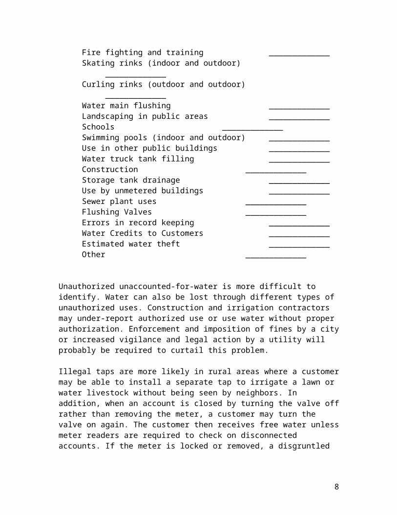
Categories for Estimating Amount of Water Used (gallons)for Authorized but Unmetered Water Uses (one year period):
Fire fighting and training _____________Skating rinks (indoor and outdoor) _____________Curling rinks (outdoor and outdoor) _____________Water main flushing _____________Landscaping in public areas _____________Schools _____________Swimming pools (indoor and outdoor) _____________Use in other public buildings _____________Water truck tank filling _____________Construction _____________Storage tank drainage _____________Use by unmetered buildings _____________Sewer plant uses _____________Flushing Valves _____________Errors in record keeping _____________Water Credits to Customers _____________Estimated water theft _____________Other _____________
Unauthorized unaccounted-for-water is more difficult to identify. Water can also be lost through different types of unauthorized uses. Construction and irrigation contractors may under-report authorized use or use water without proper authorization. Enforcement and imposition of fines by a city or increased vigilance and legal action by a utility will probably be required to curtail this problem.
Illegal taps are more likely in rural areas where a customer may be able to install a separate tap to irrigate a lawn or water livestock without being seen by neighbors. In addition, when an account is closed by turning the valve off rather than removing the meter, a customer may turn the valve on again. The customer then receives free water unless meter readers are required to check on disconnected accounts. If the meter is locked or removed, a disgruntled customer may resort to illegal access. Meter readers need to be trained to spot the various types of illegal taps.
Large unaccounted-for water losses make it difficult to reliably maintain minimum pressures A distribution system must not only provide an adequate quantity of water, it also must be designed to provide sufficient pressure to satisfy normal customer
5

requirements. All water mains are sized to maintain a normal working pressure of at least 35 pounds per square inch (psi). However, pressures in the system under normal operating conditions should range between 50 and 80 psi. DEP requires a minimum operating pressure of 20 psi at the customer’s service connection.
Pipes Used in Water Systems and Problem Consideration
Standards for Piping Materials
Providing the proper materials in a water system will ensure long service life, minimal service interruptions and high reliability. All components used in a water distribution system should conform to the latest standards issued by the American Water Works Association (AWWA), or by the ANSI/NSF standards. The NSI/NSF standards cover potable water for pipe sizes less than 4 inches in diameter. These organizations have established standards for water supply materials which ensure the materials used will not leach contaminants into the drinking water and meet minimum strength criteria.
In general, water distribution systems will use three types of pipe for water distribution and transmission for sizes in the range of 4” to 12” diameter: cast grey iron, cast ductile iron and polyvinyl chloride (PVC) pipe. AWWA uses an standard diameter system (C900 for ductile iron) that ensures that ductile iron and (SDR for PVC) PVC pipe have the same outside diameter so they can be connected using standard fittings.
Materials Used for Pipelines in Water Systems
The amount of water a pipe can carry is a function of its size and the smoothness of the interior surface. The following are summaries of the various types of pipecommonly found in water systems:
Iron Pipe:
There are two types of cast iron pipe, grey cast iron and ductile iron. In the water industry “cast iron pipe” is used to identify the older grey cast iron pipe and the newer ductile cast iron pipe has been shortened to ductile iron pipe.
Grey cast iron pipe is no longer used in water systems because, unlike the more modern ductile iron pipe, it is brittle and can be broken when hit or placed under stress. Cast iron pipe is also susceptible to corrosion when it comes in contact with corrosive water or with corrosive soils. Because cast iron has been used for over one hundred years in water systems, it is frequently found in systems built prior to 1970.
Ductile iron was first used in public water systems in 1948 and is manufactured differently than cast grey iron. The manufacturing process makes it less rigid, lighter, and it offers better corrosion resistance. Today’s ductile iron is lined on the inside with a cement mortar or epoxy lining to prevent the electrochemical corrosion that results in tuberculation, and to provide a smoother pipe interior which will provide less friction to
6

the water flowing through it. Older unlined cast iron pipe will develop twice the friction head than lined pipe which greatly reduces the pipe’s carrying capacity.
On the exterior of the pipe an extra bituminous coatings or a polyethylene cover placed during construction, is sometimes used when the pipe is to be placed in corrosive soils. These disrupt the ability of corrosive water to transport metal ions protecting the pipe from damage.
Today’s pipe joints are push on joints that also provide for significant deflection of the pipe. Flanged and restrained mechanical joints are used above ground or in special underground applications. Older cast iron pipes were joined using a bell and spigot connection. Some of these connections may contain a lead joint. In these cases it is important to control the corrosiveness of the water to prevent leaching into the drinking water.
The major disadvantage to ductile iron pipe is its weight that requires larger equipment to place it. Thus PVC pipe is frequently used in applications that are 12 inches in diameter where it has a distinct weight advantage. Ins some cases it is wise to use ductile iron pipe in smaller sizes where extra protection is desired such as under pavement or parking areas where heavy loads are expected.
Steel Pipe:
Steel pipe is lighter than ductile iron and has a high tensile (pulling orstretching) strength, some flexibility, is easily installed and jointed, low in cost,readily welded together, and easily assembled, handled and transported.Its major disadvantage is that it is more subject to corrosion and therefore must be lined or coated inside and out. The pipe must be handled carefully during installation because areas with loss of coating will be acted on by corrosive water. Thus the types of pipes are typically protected with Cathodic protection systems. Pipe coatings or linings might be a cement or epoxy material and the exterior could be coated with epoxy or mastic or with a protective plastic wrap.
Steel pipe is typically not used in water systems in larger sizes because of corrosion concerns. In smaller sizes a special galvanized steel pipe that is coated with zinc was frequently used prior to the introduction of PVC pipe in the 1970’s and was used in water service installations.
Concrete Pipe:
Concrete pipe is durable, has good internal corrosion resistance, low maintenance features and is easily installed. Because of its weight and cost, concrete pipe is typically only used in sizes greater than 36” in diameter where it becomes cost competitive.
In water applications a specially manufactured prestressed reinforced concrete pipe (RCCP) is used. RCCP has reinforcement with wire strands to provide more resistance to
7
loads and pressure. Besides its weight, another disadvantage of concrete pipe is that it is, difficult to tap, needs special fittings, and may deteriorate in aggressive soils. Additionally, since manufacturing processes somewhat vary, matching outside diameters may be difficult, thus special fittings and the use of specialized contractors are required for repairs.
Asbestos-Cement:
Asbestos cement pipe was quite popular until it was found that under corrosive conditions, it can release asbestos fibers which may be harmful to people’s health. DEP regulations regulate the amount of fibers permissible (7 MFL) in the water distribution system. Health concerns affects both those in the pipe manufacturing business and those involved in pipe replacement, repair, or tapping as fibers will be transported in the air and lodge in lung tissue.
AC pipe will not burn, deteriorate, or corrode and has a high tensile strength. It is light (about half the weight of ductile iron pipe), very smooth inside so offers little friction to water flow, and it is easily tapped, cut, and machined in the field.
Disadvantages of using AC pipe include easy breakage when bent and vulnerability to impact damage. It is also difficult to locate when buried and tracer wires must be used. Asbestos fibers may leach out of the pipe when it is transporting very soft water. Respirators should be worn when there is the possibility of asbestos fibers becoming airborne during repair.
Plastic Pipe:
The use of plastic pipe has become very popular in water distribution systems for smaller size main installation, below 16” and for service lines. The types of plastic pipe in general use are PVC (polyvinyl chloride), PE (polyethylene), and PB (polybutylene).
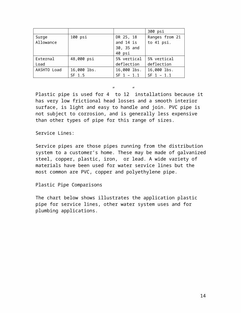
PVC pipe used for water distribution and transmission must comply with AWWA C900 and C905 specifications. Because most of a small water system will consist of pipe in the 4” to 12” sizes comparisons of ductile iron pipe and PVC pipe is shown in the following table.
Category Ductile IronANSI/AWWA C150/A21.50ANSI/AWWA C150/A21.50
PVCANSI/AWWA C900
PVCANSI/AWWA C905
Sizes 3” – 64” 4” – 12” 14” – 48”Laying Lengths 18’ and 20’ 20’ 20’Pressure 100, 150, 200, 250, 300
and 350 psiDR 25, 18 and 14 is 100, 150 and 200 psi
DR 51, 41 and 32.5,26, 25, 21, 18 and 14 is 80, 100, 125, 160 165, 200,
8

235 and 300 psiSurge Allowance 100 psi DR 25, 18 and
14 is 30, 35 and 40 psi
Ranges from 21 to 41 psi.
External Load 48,000 psi 5% vertical deflection
5% vertical deflection
AASHTO Load 16,000 lbs. SF 1.5
16,000 lbs.SF 1 – 1.1
16,000 lbs.SF 1 – 1.1
Plastic pipe is used for 4” to 12” installations because it has very low frictional head losses and a smooth interior surface, is light and easy to handle and join. PVC pipe is not subject to corrosion, and is generally less expensive than other types of pipe for this range of sizes.
Service Lines:
Service pipes are those pipes running from the distribution system to a customer’s home. These may be made of galvanized steel, copper, plastic, iron, or lead. A wide variety of materials have been used for water service lines but the most common are PVC, copper and polyethylene pipe.
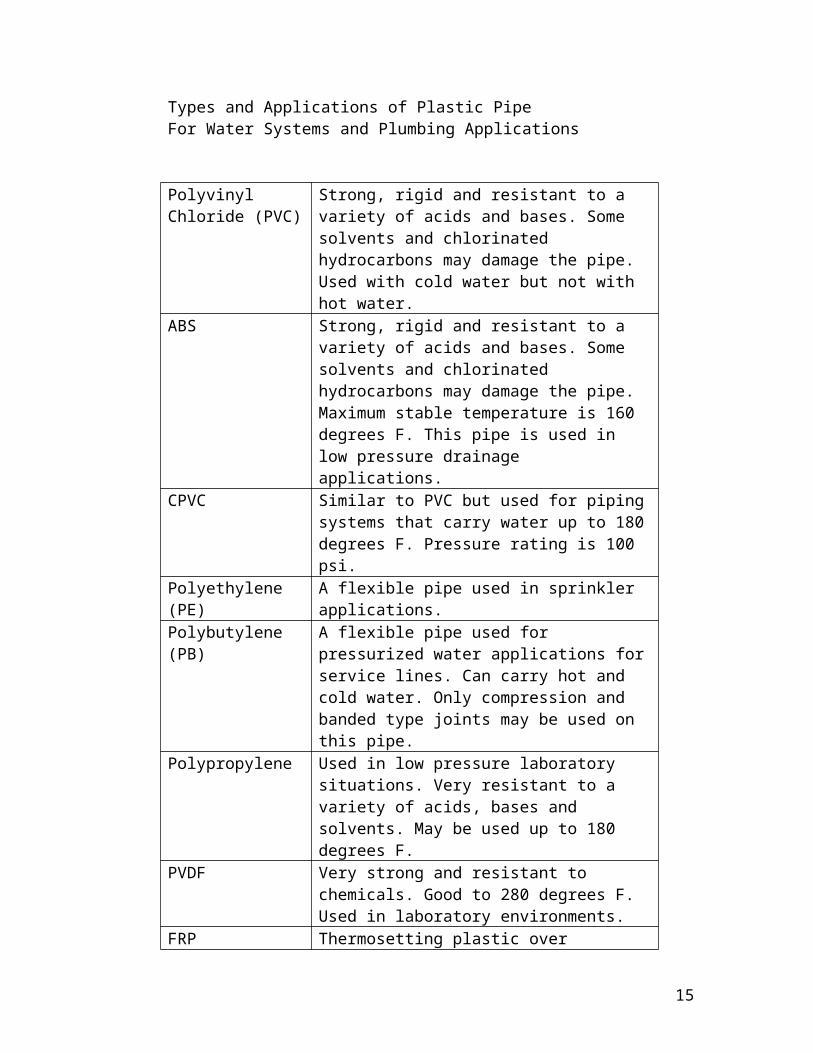
Plastic Pipe Comparisons
The chart below shows illustrates the application plastic pipe for service lines, other water system uses and for plumbing applications.
9
Types and Applications of Plastic PipeFor Water Systems and Plumbing Applications
PolyvinylChloride (PVC)
Strong, rigid and resistant to a variety of acids and bases. Some solvents and chlorinated hydrocarbons may damage the pipe. Used with cold water but not with hot water.
ABS Strong, rigid and resistant to a variety of acids and bases. Some solvents and chlorinated hydrocarbons may damage the pipe. Maximum stable temperature is 160 degrees F. This pipe is used in low pressure drainage applications.
CPVC Similar to PVC but used for piping systems that carry water up to 180 degrees F. Pressure rating is 100 psi.
Polyethylene (PE) A flexible pipe used in sprinkler applications.Polybutylene (PB) A flexible pipe used for pressurized water
applications for service lines. Can carry hot and cold water. Only compression and banded type joints may be used on this pipe.
Polypropylene Used in low pressure laboratory situations. Very resistant to a variety of acids, bases and solvents. May be used up to 180 degrees F.
PVDF Very strong and resistant to chemicals. Good to 280 degrees F. Used in laboratory environments.
FRP Thermosetting plastic over fiberglass. Very strong, chemical resistant and heat tolerant to 220 degrees F. Used in the laboratory.
Copper Pipe
Copper pipe is available and frequently used in service lines and in residential plumbing. There are three types of copper shown below with only type K recommended for domestic service applications:
10
Types of Copper Pipe Used In Water Systems and Plumbing Applications
Type Wall Thickness Flexibility Application
Type K Heavy Wall Soft Used in buried locationsType L Medium Wall Hard Used for inside plumbing
applicationsType M Light Wall Hard Used in hot water heating for
drain lines
Lead Pipe
The use of lead pipe is prohibited in water systems because of the tendency for dangerous levels of lead to leach into the water system.
Because lead pipe and or lead goosenecks were used for meter settings in the past, water systems can have lead problems when the water is corrosive water. In these cases lead pipe service lines and fittings may need to be replaced to eliminate lead in drinking water which has leached from the pipe interior.
Corrosion control treatment can minimize these types of problems in most cases. The operator is referred to the Florida Rural Water Association Small Water Systems Manual for a discussion on controlling corrosion in water.
Leaks and Leak Detection
Causes of Leaks
A variety of pipe materials are used in a public water supply system to carrywater under pressure. They include PVC, ductile iron, steel, concrete and asbestos cement pipe. All piping systems have useful life and can develop problems as they age. If the water or soils are corrosive pipelines can and do develop leaks. Since water systems are under pressure, leaks can result in large losses of water from the system. A small 1/4 “ leak can result in a water loss of up to ½ million gallons per month.
Leaks in Water Mains
Unaccounted for water is a major source of revenue loss for many water systems. In addition, the cost for chemicals and electrical costs are hidden but can be substantial. Leaks can also lead to structural damages to adjacent structures such as pavement and other utility pipelines. Significant capital costs for new treatment and distribution systems can many times be avoided by identifying leaks and taking corrective action.
11
Leaks can be identified by physical inspection for high flows in adjacent sewers and standing water in dry periods and by use of leak detection equipment. Small leaks give off a characteristic high-pitched sound that can be identified with amplifying equipment. The Florida Rural Water Association has this equipment and can assist small water systems with leak detection studies.
Leaks in Service Lines
Like the larger pipes, older service lines made out of ferrous materials will tend to corrode over a long period of time. Galvanic corrosion is a particular kind of corrosion that is caused by corrosive water that can lead to a problem known as tuberculation. Tuberculation is an electrochemical phenomenon where metal ions given up by the pipe wall are deposited inside the pipe eventually building a mass that restricts the flow of water to the customer’s home. Once the mass builds up to a size that restricts flow, it can not be removed and the pipe must be replaced.
Copper pipes are also susceptible to corrosion and can actually develop pin-hole leaks if the corrosive condition is not corrected.
Pipe Installation, Maintenance and Repair Requirements
Requirements for Water Transmission and Distribution Systems
The methods for sizing and construction for water distribution facilities must comply with the “Recommended Standards for Water Works,” and the standards established by the Florida Department of Environmental Protection (DEP.) The DEP standards are found in the Florida Administrative Code in Chapter 62. DEP regulates all pipelines that convey water for public consumption and have a diameter of at least 3’ or greater. Any alteration of a pipeline supplying the public with water requires a permit from DEP.
The small water treatment plant operator will frequently be called upon to inspect or initiate repairs or addition to pipeline systems. If a water main break results in a service outage to more than 350 people or 150 service connections or if a repair duration keeps a single service connection out of water for more than 8 hours DEP must be notified.
Water Main Design
The minimum water pipeline size is based on a hydraulic analysis of the maximum day water demand plus fire flow requirements or peak hour demands, which ever is greatest. All parts of the system must maintain a minimum 20 psi residual pressure throughout the distribution system and at each service connection. Dead-End and Looping of Water Mains
Looping of water mains is always desirable. Looping helps in maintaining pressure and eliminating points of the water system that will require flushing. Dead ends water lines
12

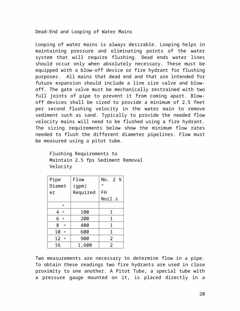
should occur only when absolutely necessary. These must be equipped with a blow-off device or fire hydrant for flushing purposes. All mains that dead end and that are intended for future expansion should include a line size valve and blow-off. The gate valve must be mechanically restrained with two full joints of pipe to prevent it from coming apart. Blow-off devices shall be sized to provide a minimum of 2.5 feet per second flushing velocity in the water main to remove sediment such as sand. Typically to provide the needed flow velocity mains will need to be flushed using a fire hydrant. The sizing requirements below show the minimum flow rates needed to flush the different diameter pipelines. Flow must be measured using a pitot tube.
Flushing Requirements to Maintain 2.5 fps Sediment Removal Velocity
Pipe Diameter
Flow (gpm)Required
No. 2 ½ “ FH Nozl.s
4” 100 16” 200 18” 400 110” 600 112” 900 216” 1,600 2
Two measurements are necessary to determine flow in a pipe. To obtain these readings two fire hydrants are used in close proximity to one another. A Pitot Tube, a special tube with a pressure gauge mounted on it, is placed directly in a flowing stream of water. The pitot gauge measures the static head of the water and its velocity head. Another pressure reading is taken of the static head inside the pipe using a conventional gauge on another hydrant. By subtracting the two measurements, the velocity head can be calculated or read from a table for the particular pitot tube nozzle dimensions.
Pipe Restraining Requirements
Pipelines need to be restrained at all valves, bends, tees, crosses and dead ends for a specified distance dependant on the size of the pipe and the water flow. The particular dimensions of a thrust block is determined by an engineer based on the soil conditions. Thus the size to the thrust block varies and is dependant on the specific conditions/circumstances and on each pipeline design. It is mandatory to provide these thrust blocks because water hammer can exert enormous pressures on portions of the distribution system and cause pipes or fittings to blow apart. Where thrust blocks can not be used the pipe must be restrained using steel rods. Restraints of one type or another must be provided to support the pipes and other components at all points where the flow of water changes direction.
13
Pipe Bedding Requirements for Water Main Support and Protection
Pipe Bedding provides the structural support to pipelines. Pipeline integrity assumes that that the pipe bedding has been installed properly. Bedding must be continuous and of uniform bedding material (gravel, sand) free of rocks or other contaminants and must be provided in the trench for all buried pipe. This will prevent future punctures and breakage by large rocks putting excessive pressure on portions of the pipe. Soil unsuitable for a proper foundation encountered at or below trench grade, such as muck or other deleterious material, must be removed for the full width of the trench and to the depth required to reach suitable foundation material to protect the pipe from settling and coming apart.
Backfill material should be tamped in layers around the pipe to provide adequate support from shifting and to protect the pipe. This will prevent undue settling and breakage. The bottom of the trench must be shaped to provide a firm bedding for the utility pipe. The utility shall be firmly bedded in undisturbed firm soil, or hand-shaped unyielding material. The bedding should be shaped so that the pipe will be in continuous contact for its full length and should be placed to provide a minimum bottom segment support for the pipe equal to springline of the pipe or one-half of the outside diameter of the barrel. Special bedding may be required, due to depth of cover, impact loadings, or other conditions. .
Mains eight inches in diameter and less should have a minimum cover of 36 inches to prevent accidental surface damage. Ten inch mains and larger should have additional cover when practical to do so.
Trench Requirements for Installation and Repair of Water Main
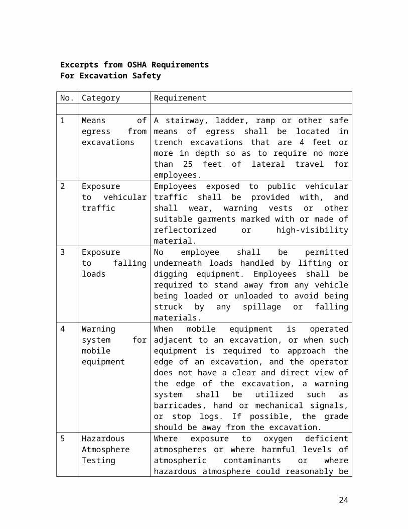
Trench safety during repair and maintenance to underground water facilities on of the most dangerous parts of a small water systems operator’s responsibilities. Fail to adhere to proper trenching requirements can result in a cave in with serious consequences including death. Therefore all excavations must be properly shored, sheeted and braced or cut back at the proper slope to provide safe working conditions, to prevent shifting of material, to prevent damage to structures or personnel working in or near the trench. The Occupational Safety and Health Administration (OSHA), and the State of Florida under the Trench Safety Act, Section 107 of the Contract Work Hours and Safety Standards Act provide minimum trench conditions for underground work. Operators should be familiar with OSHA’s Excavations: Hazard Recognition in Trenching and Shoring Manual that can be obtained on-line from OSHA at osha.com.
14
Excerpts from OSHA RequirementsFor Excavation Safety
No. Category Requirement
1 Means of egress from excavations
A stairway, ladder, ramp or other safe means of egress shall be located in trench excavations that are 4 feet or more in depth so as to require no more than 25 feet of lateral travel for employees.
2 Exposure to vehicular traffic
Employees exposed to public vehicular traffic shall be provided with, and shall wear, warning vests or other suitable garments marked with or made of reflectorized or high-visibility material.
3 Exposure to falling loads
No employee shall be permitted underneath loads handled by lifting or digging equipment. Employees shall be required to stand away from any vehicle being loaded or unloaded to avoid being struck by any spillage or falling materials.
4 Warning system for mobile equipment
When mobile equipment is operated adjacent to an excavation, or when such equipment is required to approach the edge of an excavation, and the operator does not have a clear and direct view of the edge of the excavation, a warning system shall be utilized such as barricades, hand or mechanical signals, or stop logs. If possible, the grade should be away from the excavation.
5 Hazardous Atmosphere Testing
Where exposure to oxygen deficient atmospheres or where harmful levels of atmospheric contaminants or where hazardous atmosphere could reasonably be expected to exist, such as in excavations in landfill areas or excavations in areas where hazardous substances are stored nearby, the atmospheres in the excavation shall be tested before employees to ensure a minimum 19.5 percent oxygen concentration.
6 Removal of Water From Trench
Employees shall not work in excavations in which there is accumulated water, or in excavations in which water is accumulating, unless adequate precautions have been taken to protect employees against the hazards posed by water accumulation. The precautions necessary to protect employees adequately vary with each situation, but could include special support or shield systems to protect from cave-ins, water removal to control the level of accumulating water, or use of a safety harness and lifeline.
7 Interruption of Natural Drainage
If excavation work interrupts the natural drainage of surface water (such as streams), diversion ditches, dikes, or other suitable means shall be used to prevent surface water from
15
entering the excavation and to provide adequate drainage of the area adjacent to the excavation. Excavations subject to runoff from heavy rains will require an inspection by a competent person (Registered PE.)
8 Stability of Adjacent Structures.
Where the stability of adjoining buildings, walls, or other structures is endangered by excavation operations, support systems such as shoring, bracing, or underpinning shall be provided to ensure the stability of such structures for the protection under the direction of a competent person (Registered PE.)
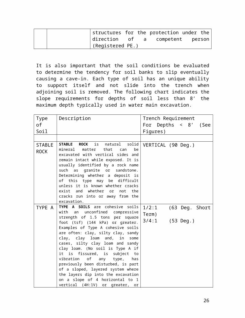
It is also important that the soil conditions be evaluated to determine the tendency for soil banks to slip eventually causing a cave-in. Each type of soil has an unique ability to support itself and not slide into the trench when adjoining soil is removed. The following chart indicates the slope requirements for depths of soil less than 8’ the maximum depth typically used in water main excavation.
Type of Soil
Description Trench RequirementFor Depths < 8’ (See Figures)
STABLE ROCK
STABLE ROCK is natural solid mineral matter that can be excavated with vertical sides and remain intact while exposed. It is usually identified by a rock name such as granite or sandstone. Determining whether a deposit is of this type may be difficult unless it is known whether cracks exist and whether or not the cracks run into or away from the excavation.
VERTICAL (90 Deg.)
TYPE A TYPE A SOILS are cohesive soils with an unconfined compressive strength of 1.5 tons per square foot (tsf) (144 kPa) or greater. Examples of Type A cohesive soils are often: clay, silty clay, sandy clay, clay loam and, in some cases, silty clay loam and sandy clay loam. (No soil is Type A if it is fissured, is subject to vibration of any type, has previously been disturbed, is part of a sloped, layered system where the layers dip into the excavation on a slope of 4 horizontal to 1 vertical (4H:1V) or greater, or has seeping water.
1/2:1 (63 Deg. Short Term)3/4:1 (53 Deg.)
TYPE B TYPE B SOILS are cohesive soils with an unconfined compressive strength greater than 0.5 tsf (48 kPa) but less than 1.5 tsf (144 kPa). Examples of other Type B soils are: angular gravel; silt; silt loam; previously disturbed soils unless otherwise classified as Type C; soils that meet the unconfined compressive strength or cementation requirements of Type A soils but are fissured or subject to vibration; dry unstable rock; and layered systems sloping into the trench at a slope less than 4H:1V (only if the material would be classified as a Type B soil).
1:1 (45 Deg.)
16

TYPE C TYPE C SOILS are cohesive soils with an unconfined compressive strength of 0.5 tsf (48 kPa) or less. Other Type C soils include granular soils such as gravel, sand and loamy sand, submerged soil, soil from which water is freely seeping, and submerged rock that is not stable. Also included in this classification is material in a sloped, layered system where the layers dip into the excavation or have a slope of four horizontal to one vertical (4H:1V) or greater.
1 1/2:1 (34 Deg.)
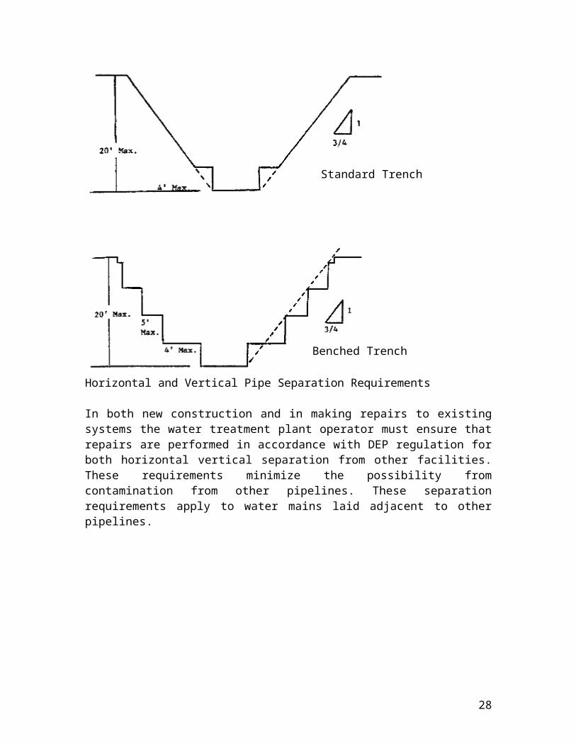
The following trench schematics illustrate how trench widths are determined.
Horizontal and Vertical Pipe Separation Requirements
In both new construction and in making repairs to existing systems the water treatment plant operator must ensure that repairs are performed in accordance with DEP regulation for both horizontal vertical separation from other facilities. These requirements minimize the possibility from contamination from other pipelines. These separation requirements apply to water mains laid adjacent to other pipelines.
17
Standard Trench
Benched Trench

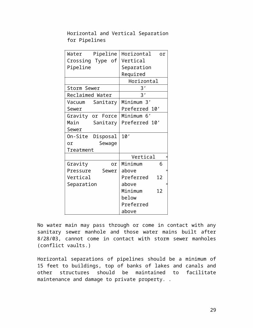
Horizontal and Vertical Separation for Pipelines
Water Pipeline Crossing Type of Pipeline
Horizontal or Vertical Separation Required
HorizontalStorm Sewer 3’Reclaimed Water 3’Vacuum Sanitary Sewer Minimum 3’
Preferred 10’Gravity or Force Main Sanitary Sewer
Minimum 6’Preferred 10’
On-Site Disposal or Sewage Treatment
10’
VerticalGravity or Pressure Sewer Vertical Separation
Minimum 6” abovePreferred 12” aboveMinimum 12” belowPreferred above
No water main may pass through or come in contact with any sanitary sewer manhole and those water mains built after 8/28/03, cannot come in contact with storm sewer manholes (conflict vaults.)
Horizontal separations of pipelines should be a minimum of 15 feet to buildings, top of banks of lakes and canals and other structures should be maintained to facilitate maintenance and damage to private property. .
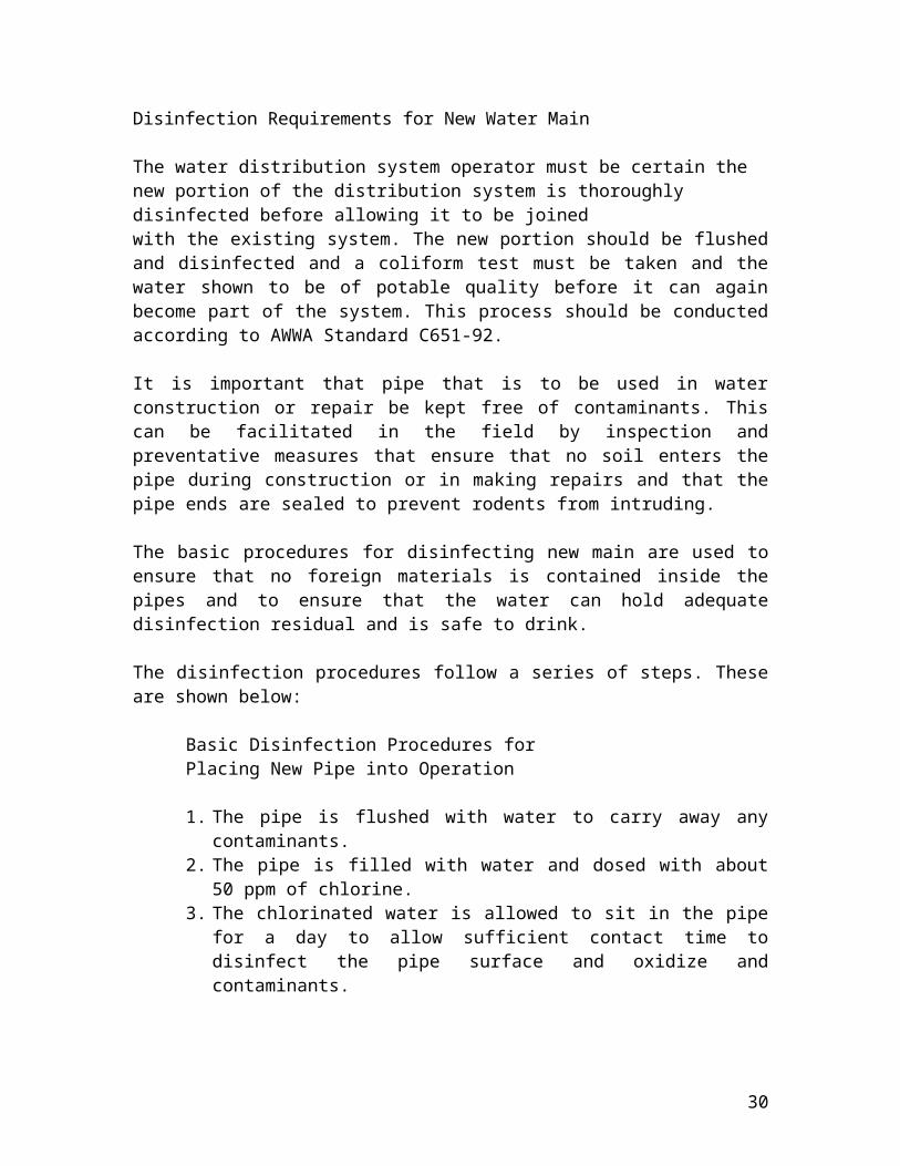
Disinfection Requirements for New Water Main
The water distribution system operator must be certain the new portion of the distribution system is thoroughly disinfected before allowing it to be joinedwith the existing system. The new portion should be flushed and disinfected and a coliform test must be taken and the water shown to be of potable quality before it can again become part of the system. This process should be conducted according to AWWA Standard C651-92.
It is important that pipe that is to be used in water construction or repair be kept free of contaminants. This can be facilitated in the field by inspection and preventative measures that ensure that no soil enters the pipe during construction or in making repairs and that the pipe ends are sealed to prevent rodents from intruding.
The basic procedures for disinfecting new main are used to ensure that no foreign materials is contained inside the pipes and to ensure that the water can hold adequate disinfection residual and is safe to drink.
18

The disinfection procedures follow a series of steps. These are shown below:
Basic Disinfection Procedures for Placing New Pipe into Operation
1. The pipe is flushed with water to carry away any contaminants. 2. The pipe is filled with water and dosed with about 50 ppm of chlorine.3. The chlorinated water is allowed to sit in the pipe for a day to allow sufficient
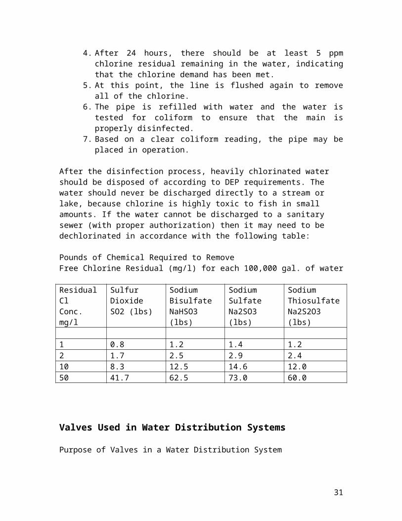
contact time to disinfect the pipe surface and oxidize and contaminants. 4. After 24 hours, there should be at least 5 ppm chlorine residual remaining in
the water, indicating that the chlorine demand has been met. 5. At this point, the line is flushed again to remove all of the chlorine.6. The pipe is refilled with water and the water is tested for coliform to ensure
that the main is properly disinfected.7. Based on a clear coliform reading, the pipe may be placed in operation.
After the disinfection process, heavily chlorinated water should be disposed of according to DEP requirements. The water should never be discharged directly to a stream or lake, because chlorine is highly toxic to fish in small amounts. If the water cannot be discharged to a sanitary sewer (with proper authorization) then it may need to be dechlorinated in accordance with the following table:
Pounds of Chemical Required to RemoveFree Chlorine Residual (mg/l) for each 100,000 gal. of water
Residual ClConc. mg/l
Sulfur DioxideSO2 (lbs)
Sodium BisulfateNaHSO3 (lbs)
Sodium SulfateNa2SO3 (lbs)
Sodium ThiosulfateNa2S2O3 (lbs)
1 0.8 1.2 1.4 1.22 1.7 2.5 2.9 2.410 8.3 12.5 14.6 12.050 41.7 62.5 73.0 60.0
Valves Used in Water Distribution Systems
Purpose of Valves in a Water Distribution System
Valves are a very important part of the distribution system because they regulate the flow of water, reduce pressure, provide air and vacuum relief, blow off or drain water from parts of the system and prevent backflow.
19
Water System Mapping Requirement
Beginning on December 31, 2005, for water systems that have over 150 service connections or serve 350 customers, must maintain an up-to-date map of their drinking water distribution system. The map must show the location and size of water mains, the location of valves and fire hydrants and the location of any pressure zone boundaries, pumping facilities, storage tanks and interconnections with other public water systems.
Requirements to a Valve Exercising and Main Flushing Program
The water provider must have a plan for exercising valves and for flushing dead end lines at least quarterly. The valve exercising process should be coordinated with other routine maintenance, such as fire hydrant inspection and maintenance. Most valves will need to be exercised at minimum on an annual basis. If not, access to the valves may be compromised by covering during a street repair process or covered up during new construction.
When using a flush valve it is important to direct water to storm drains or retention areas so that the water flow does not result in flooding, environmental damage or erosion. The following table illustrates the minimum information that should be recorded in a valve maintenance program.
Information to be Collected in a Valve Exercising Program
1 Unique Valve identification number 2 Visibility and proper elevation 3 Accessibility 4 Location and GPS coordinates 5 Manufacturer6. Size and Style of Valve7. Number or turns and direction for opening8. Check for leakage with detection equipment9. Condition of valve10 Age of valve in system
Valve Operation and Water Hammer
Valves of any size need to be operated slowly. Water hammer is caused by closing the valve too quickly. When water is suddenly stopped, shock waves are generated, which cause large pressure increases throughout the system.These shock waves travel quickly and can cause extensive damage, sometimes splitting pipes or blowing fittings completely off the system. Frequently in the operation of valves, conditions cause a partial vacuum or void to occur on the
20
downstream side of a valve. These voids will fill with low-pressure vapors from the water. When these pockets implode or collapse, they create a mechanical shock causing pockets of metal to break away from the valve surface.
Another problem in water distribution systems is noisy or vibrating valves. This is usually an indication that cavitation is occurring. Cavitation will eventually render the valve unsuitable for service. The most common cause of cavitation is that the that the valve is partially closed.
Types of Valves and Their Application in Water Distribution Systems
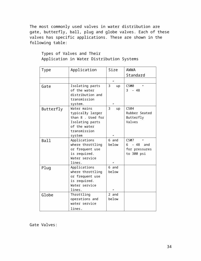
The most commonly used valves in water distribution are gate, butterfly, ball, plug and globe valves. Each of these valves has specific applications. These are shown in the following table:
Types of Valves and Their Application in Water Distribution Systems
Type Application Size AWWA Standard
Gate Isolating parts of the water distribution and transmission system.
3” up C500 3” – 48”
Butterfly Water mains typically larger than 8”. Used for Isolating parts of the water transmission system
3” up C504 Rubber SeatedButterfly Valves
Ball Applications where throttling or frequent use is required. Water service lines.
6”andbelow
C5076” – 48” and for pressuresto 300 psi
Plug Applications where throttling or frequent use is required. Water service lines.
6”andbelow
Globe Throttling operations and water service lines.
2”andbelow
Gate Valves:
Gate Valves are used to isolate sections of the distribution system to permit emergency repairs without interrupting service to large numbers of customers. In the gate valve, a sliding flat metal disc is moved at right angles to the direction of flow by a screw operated stem. In larger valves there are two discs. The discs can be taken completely out of the flow chamber therefore, the valve provides very little resistance to flow when it is opened. When these valves are left open for long periods of time debris will accumulate in the seats. For this reason the valves must be periodically operated.
21

Butterfly Valves:
The butterfly valve has a disc which rotates which filling the full diameter of the pipe. The disc rotates on a shaft to allow the flow of water under open conditions. Butterfly valves have the advantages of ease of operation, small space requirements, low cost, minimum maintenance and low head loss compared to other valves. They are frequently employed in lines 16” and above in diameter. Unlike gate valves, they can be used for throttling. The main disadvantage is that they block cleaning equipment used for removing deposits in pipes and pipe walls.
Ball Valves:
The movable part in a ball valve is a ball with a cylindrical hole bored through it. When the ball is in one position there is a straight passage through the valve, but when it is rotated 90 degrees the flow is blocked. Ball valves should be operated either closed or opened all the way. They can withstand high pressures and are very reliable.
Plug Valves:
Plug valves are most often used as corporation stops on service lines. They may have a tapered or cylindrical plug with an opening through the side which can be turned to open, restrict, or close the flow.
Globe Valves:
Globe valves are very efficient in either flow or pressure regulation. These are used in plumbing applications on lines 2” and less in diameter. This valve uses a disc that is raised or lowered onto a seat as in the common home faucet. The water flow is stopped when the disc contacts the seat.
Diaphragm Valves:
A diaphragm valve uses a flexible piece (usually rubber or leather) inside the valve’s body that can be adjusted up or down using an attached stem to block or regulate the flow of water. These valves are frequently employed to regulate pressure for filling water tank. When the valve is used to shut water off coming into a water tank it is called an altitude valve.
Check Valves:
A check valve uses a hinged disc which close flow openings when the flow is reversed. Check valves are often equipped with a weight and spring that assists the valve in closing rapidly under flow reversal. The operator must insure that the check valve is properly adjusted and not slamming closed which is a cause of water hammer.
22

Blow Off Valves:
Blow off valves must be provided at the end of any dead-end main to provide a flushing point. Debris will settle out in dead-end mains and cause a chlorine demand that will adversely affect chlorine residual. For this reason DEP requires each water system that serves 350 people or more to have a flushing program for dead-end mains.
Valves are typically located at water connections and at intersections in residential areas and on 1,000 foot minimum intervals with large water transmission runs. The purpose of isolation valves is to minimize the amount of the water system that has to be shut off to initiate repairs. Typically municipal agency will require valves at minimum 500’ intervals in areas with residential customers.
Fire Hydrants
Types of Fire Hydrants
If the water system is designed to provide fire protection, the water lines and the hydrant connections to the distribution system must be a minimum of six inches in diameter in order to supply required fire flow. Fire hydrants must be placed at least 3’ away from any sanitary or storm sewer.
Fire hydrants are of two types the wet and dry barrel. The wet type of hydrant is typically used for flushing purposes. Fire hydrants in water distribution applications are the wet barrel type which means the operating valve is located at the bottom of the hydrant allowing the hydrant body to fill when the valve is opened. A special fire hydrant wrench is used to turn on the hydrant. Pipe wrenches should never be used to operate a fire hydrant because they will damage the operating nut rendering them inoperable.
Fire hydrants have two nozzles, a 2 ½ inch hose nozzle and 4 ½ inch pumper nozzle. Nozzle ends are equipped with protective caps.
Operation and Maintenance of Fire Hydrants
Fire hydrants are typically provided at minimum intervals of 500’ to permit the use of standard fire hose in case of fire. Fire hydrants should also be located at every street intersection in residential areas. Besides fighting fires, fire hydrants can be used for flushing mains after main break repairs to prevent sediment from reaching customer’s homes. To accomplish this hydrants are flushed nearest the source of the problem first moving out into the system. Fire hydrants are also used as access points to determine the pressure and flows in distribution piping.
Hydrant inspection and maintenance is essential to insure that the hydrant is operational during a fire. Flushing must take place at least once per year to prevent sediment build up
23
and ensure operation. The table below provides the information that should be collected on a basic fire hydrant inspection program:
Information to be Collected in a Fire Hydrant Inspection Program
# Item
1 Pressure and Flow test2 Loose or missing caps and cap chains3 Lost or damaged gaskets4 Peeling or wearing paint5 Leakage inspection assisted by a listening device6. Lubrication of threads and operating nut7. Accessibility and adequate clearance from other
structures8. Visibility and proper elevation 9. On condition at isolation valve10 Unique FH identification number11. Location and GPS coordinate
Flow Testing Fire Hydrants
A flow test is conducted in accordance with AWWA recommendations that identifies the capacity of individual fire hydrants under normal demand conditions. Flow is determined by using two fire hydrants and reading the flow from a pitot tube at the test hydrant and the residual pressure residual at a reference hydrant connected to the same main. The flow rating is then determined based on a reference pressure of 20 psi.
Tops of fire hydrants are often painted by to designate their capacity. These are shown below:
Standards for Identifying Flow Capacities of Fire Hydrants
Class Color GPM
AA Blue > 1500A Green > 1000B Orange > 500C Red < 500
24

Fire hydrants must conform to the latest AWWA specifications C502. Typical fire hydrants will be the use a hydrant branch that is six inch in diameter and have a six-inch isolation gate valve on the branch as close as possible to the main.
Hydrants in traveled areas are usually furnished with a breakaway feature that will break cleanly upon impact. The valve stem will also break with impact in these types of hydrants.
In commercial/industrial areas hydrants must be installed on a minimum 8-inch main and hydrants in residential areas installed on a minimum 6 inch looped mains to provide adequate fire flow.
Each fire hydrant should be capable of delivering a flow of at least 500 gallons per minute with a residual pressure of not less than 20 psi.
Water Storage Systems
Hydropneumatic Tanks
Small water systems may have a small amount of storage in the form of ahydropneumatic tank. Either a standard pressure tank with an air/water interface, or a captive air tank with no air/water interface. Other systems might have ground level concrete or steel storage tanks or elevated steel tanks which serve the system by gravity.
Small hydropneumatic pressure tanks, are used to maintain pressure within thedistribution system and to prevent well pumps from cycling too frequently. Larger hydropneumatic tanks use on-site, permanent, air charging devices to maintainthe needed air pressure within the vessel. The tank should have a sight glass so the air/water ratio in the tank can be observed and adjustments made.
Storage Reservoirs
Concrete or steel storage tanks will provide a greater amount of storage capacity than a hydropneumatic tank and may provide sufficient fire flows. They also will continue to operate for a period of time during a power outage.
Many small water systems have elevated steel tanks or ground level concrete or steel tanks. These storage facilities may have openings which could allow contamination to enter, so it is vital to be certain these avenues are closed. All water distribution storage tanks should be covered to protect against contamination. All of these tanks should be equipped with vents, an access hatch, overflow outlets and drains. The vent(s) should be turned down and screened to prevent the entrance of dust, birds, insects and other vermin. The drain and the overflow pipe should also be screened and designed with a splash pad or other means to prevent erosion when overflow or drainage occurs. The access hatch should have an overlapping, gasketed, locking, shoe box-type lid.
25
Storage tanks should be drawn down at least once a year for a complete inspection, inside and out. Inspection should include ensuringthe access hatch lock is operable and the lid is of shoe-box style to prevent contaminant entry. Inspection of the vent is also necessary to ensure the screen is in good condition and prevents rodent or reptile entry to the tank.Many small systems contract with professional tank maintenance and repairfirms to have their tanks inspected every few years. The inspection would cover interior and exterior tank coating condition. After the inspection the tank should be thoroughly disinfected using an AWWA standard procedure, before being placed back on line.
If a new interior coating is needed, an ANSI/NSF approved substance must be used. Interior paint must be properly applied and cured, so no tastes, odors or toxic materials are leached into the water. Procedures must also be implemented to maintain system pressure and service while the tank is off-line.
Tank Maintenance and Inspection Requirements
Bacterial Growth Mechanisms in Water Storage Tanks
Substances essential for bacteriological growth such as nitrogen, phosphorus, trace metals and carbon are found in source water in various degrees and will pass through in small amounts into the water distribution system. Storage reservoirs and dead end lines provide sites for the accumulation of sediment that concentrates this material and encourages microbial habitation. This condition is exacerbated in water storage tanks because the water is seldom drawn completely down. Since water tanks are located in remote areas away from the water treatment plant and water sits for long periods in storage in contact with the air, residual chlorine tend to drop in these tanks. For this reason, removal of the sediment and movement of water in storage are the best methods for minimizing these problems.
High ambient temperatures intensify the growth of bacteria when sediments in the tank are present. In addition, the concentration of sediment and resultant slime growth helps to protect organisms from the action of residual chlorine. In these instances loss of chlorine residual and regrowth of bacteria is possible. For these reasons, DEP requires that sediment be removed at minimum, one time per year.
Chloramines and Nitrification
Nitrification is a common problem faced by utilities using chloramines for distribution system residual maintenance. Nitrification involves the growth of ammonia-oxidizing bacteria and the resulting production of nitrite, which exerts a chloramine demand. This can lead to a loss of chloramine protection. Once the conditions that favor nitrification have been established it will be difficult to bring the situation under control. For this reason, if chloramines are being used, tank residuals should be measured frequently and a drop in residual is a signal to initiate corrective actions.
26

Nitrification Cycle in a Water Storage Tank
Nitrification control measures include using higher chloramines residuals, yearly conversion to free chlorine under stressed conditions and aggressive flushing and movement of water in the water distribution system. Higher levels of chlorine will result in noticeable chlorinous odors and taste in the water as shown in the following chart. Aggressive flushing may result in complaints about water wastage and can move sediment into customer’s plumbing generating complaints. For this reason nitrification prevention is always preferable over nitrification corrective actions.
Sensory Threshold Concentration for Chlorine Residuals (mg/l)
Compound Odor Flavor Reqd. Residual
Hypochlorous Acid 0.28 0.24 0.20Hypochlorite Ion 0.36 0.30Monochloramine 0.65 0.48 0.60Dichloramine 0.15 0.13Trichloramine 0.02 ND
Krasner and Barret, 1985
Booster Pumps and Water Pumping Stations
A booster pump is used to increase the pressure in the mains, pump water from ground storage tanks into the water system or to supply water to an elevated or higher level storage tank. Booster pumps are centrifugal pumps and care should be used in their operation. An operator should be concerned about three critical points: installation, alignment and protection for operators from moving parts. If the initial installation and the alignment are properly done, the pump should give few problems and require little maintenance other than routine checking of the packing and lubrication of bearings. Manufacture’s instructions must be followed for packing and lubrication requirements. Protection from moving parts is critical as unprotected and rapidly rotating shafts can capture loose clothing and cause severe injury. As for all pumps, frequent inspection of the pump for heat, unusual vibration and noise are important parts of a maintenance program.
1 Sediment and Deposits2 High Temperature3 Long Detention Time4 Low Chloramine Residual5 High Nitrite Levels6 High Bacterial Counts7 Coliform Regrowth
27
Requirements for Repairing Broken Water Mains
Minimum Precautions to Prevent Contamination During Repairs
In making pipeline repairs it is always important to maintain a positive pressure in the distribution system until the repairs are initiated. A positive pressure ensures that no contamination is entering the distribution system. Precautionary measures during the repair should be taken to ensure that contamination does not enter the water system and that all repair parts and equipment that comes in contact with the water is disinfected. Extreme care must be taken when making repairs to avoid contamination.
Customers in the area which will be without water must be notified as quickly as possible that repairs are to be initiated and requested to not open their taps until notified by the system operator. Notification before the water is shut off is best so the customers can make sufficient preparations and not to expose the customer to possible backflow conditions.
Repair trenches should remove the contaminated water to below the broken pipeline to prevent water intrusion into the public water system. It is important to dig out the trench from under the pipe so the pipe is exposed and the repair clamp can be installed freely. This will also allow for clean replacement pieces to be installed. Trenching and trench safety practices should be in conformance with OSHA and State requirements.
The repair clamp and the piece of pipe to be inserted should be disinfected prior to use. This is especially important if these pieces of equipment have been sitting around in a storage yard, exposed to the elements. Before the repair is made, calcium hypochlorite granules should be placed into the pipe in sufficient quantities to disinfect the portion being repaired. This should result in a chlorine concentration of 100 to 300 mg/l in the pipe. In wet excavations, large quantities of hypochlorite should be applied to open trench area to lessen the danger of contamination. The interior of all pipes and fittings used in making the repair must be swabbed or sprayed with a one percent hypochlorite solution before they are installed.
Once the repair has been completed, water should be held in the line as long as possible to give the opportunity for the chlorine to kill the bacteria. In most cases, the operator will be asked to get the system back into service as quickly as possible. Before placing the line in operations, the system must be flushed to remove any sediment and high chlorine residual that may be present. Nearby customers should be notified and asked to flush their lines. It is recommended that the operator assist them with this activity. Coliform samples should be taken on both sides of the main break after pipe repair. If positive results are found, the system should again be flushed and samples taken until no further contamination is apparent.
28
General Water Distribution Conditions for Boil Water Notices
In instances where water can be contaminated, DEP requires that the public be notified and that “boil water notices” be issued. The Florida Department of Health (DOH) is responsible for conducting an environmental health program that protect the public from exposure to contaminants in water. DOH identifies the various conditions found in distribution systems that dictate boil water notices. These are listed below:
Fecal Contamination
A precautionary boil water notice shall always be issued in cases where confirmatory water samples indicate the presence of fecal coliform bacteria, E. coli, or other waterborne pathogens. The presence of such indicates an acute threat to the public's health and warrants immediate action by the public water system and public health officials to alert consumers. Zero or Negative Pressure in Distribution System
A precautionary boil water notice shall always be issued in cases where pressure in the water distribution system has been reduced to zero, or a negative pressure has resulted. Examples of such system wide events include water treatment plant or pump station shut downs due to equipment failure, power outages, emptying of storage tanks, or draining of the system during major fire events.
Drop in Water Pressure Below 20 psi with Aggravating Factors Present
A drop in water pressure in a water distribution system is a signal of the existence of conditions which could allow contamination to enter the public water system through backflow by back-pressure or back-siphonage. Precautionary boil water notices may be issued in cases when there is a historical record of inadequate disinfectant maintenance in the water distribution system, or analytical records indicate persistent microbiological or turbidity problems or an inadequate backflow prevention program exists. Water pressure falling below the regulated service level of 20 psi does not, in the absence of other aggravating factors, necessarily constitute an imminent health hazard. Such factors include the presence of tall buildings not adequately protected against backflow where the static head exceeds the residual main pressure. The decision to issue the precautionary boil water notice would be made on a case by case basis and based upon professional judgment of all available data that may indicate the extent of the problem such as type of facilities affected, duration of the low pressure condition, and possibility of infiltration into the potable water system. Microbiological samples shall be collected immediately within the area affected, and measures taken expeditiously to restore the integrity of the water system.
29
Water Main Breaks that Affect Bacteriological Water Quality
Precautionary boil water notices must be issued in cases of water main breaks, or planned distribution system interruptions, which are deemed an imminent public health threat by the state health office or local county health department or will affect the bacteriological quality of the drinking water unless the public water system can demonstrate, by sound engineering judgment, that the integrity of the water system has been maintained. Assurance from the public water system that an outflow of water has been continuously maintained and no nonpotable water, soil or other potentially contaminated material has entered, or may enter, the broken water main during the event, will serve to demonstrate that the integrity of the system has been maintained. In cases of brief interruption in service, the affected water main should be immediately repaired, flushed, disinfected, sampled, and monitored for chlorine residual according to ANSI/AWWA Standard C651-92. If these measures are taken, advisories (not boil water notices) should be issued if temporary changes in water quality are expected to occur.
Requirements for the Notification of Regulatory Agencies and the Public
Under emergency conditions, or following confirmation of the presence of microbiological pathogens within a public water supply, the public water system, as required within s. 403.857, F.S. the water provider must notify the local county health department, the DEP, and the affected public as soon as possible, but not later than 24 hours of the occurrence. In response, the DOH will coordinate with DEP, other state and local governmental agencies, and the public water system, immediate actions which are to be taken (including the issuance of a precautionary boil water notice) to minimize danger to the public. Adequate communication between DEP, the DOH, and the public water system is essential to ensure that all agencies are fully informed prior to the issuance of a precautionary boil water notice. Whichever department issues the notice will also be responsible for rescinding it.
Service Lines and Water Meters
Service Lines
Service lines carry water from a main (at the street) to the customer's house. Since the customer only requires a relatively small amount of water, service lines are typically much smaller than mains. Again in contrast to mains, service lines require a relatively extensive network of equipment to control and monitor the flow of water to the customer. We will briefly discuss this equipment below.
30
A typical service line will involve at least three valves (known as stops.) A corporation stop is used to connect the service line to the main but is not accessible after construction since it is typically buried under the pavement of the street. A curb stop, located further along the line, is typically used by the operator to turn the water in the service line on and off. The meter stop, located beside the meter, is used to isolate the meter for installation or maintenance. In many cases a fourth valve is added on the house side of the meter which will be used by the homeowner to turn off water during plumbing operations. More information about valves is given in the next section.
Water Meters
Water meters provide a method for measuring flow and allocating charges for water based on the amount and type of use of water. Water meters are used to measure flow from wells, finished water and from storage facilities. Water meters are also used to measure water used by customers. When used in this manner the water meters are the utility’s cash register and the successful financial management of a water system depends on how accurately these meters measure the water consumption. Meters are typically read every month, either by the customer or by a water provider representative.
There are a wide variety of types of meters and their proper application is the most critical step in ensuring accurate measurement of water flow. Meter guides are provided by meter manufactures for their product. The following table is representative of meters used for residential and commercial installation and illustrates the proper application of water meters.
31

Types of Water Meters and Their Application
Type of Meter
Typical Application
Sizes Flow Type Flow RangeGPM
AccuracyAll ranges
Displacement Meters
Residential and Small Commercial
5/8” ¾ ”1”1.5”2”
Intermittent Flow
1 – 202 – 303 – 505 – 1008 - 160
+ 1.5%(continuous flow at max. rate is 50% of rated value)
Multi Jet Meters
Residential and Commercial Irrigation
5/8” ¾ ”1”1.5”2”
Intermittent Flow
1 – 202 – 303 – 505 – 1008 - 160
+ 1.5%(continuous flow at max. rate is 50% of rated value)
Propeller Raw (dirty) Water Measurement
3” to36”
10:1Flow Range
Varies + 2.0%
Turbine Meter
CommercialAnd Industrial
1.5”2”3”
100:1Flow Range
4 - 1204 -1605 - 350
+ 1.5%(intermittent flows at 25% above max.)
Compound WholesaleCustomers
varies 1000:1Flow Range
Varies + 1.5%
Courtesy Sensus Metering Systems
Use of a meter under sustained high flow will result in premature wear and inaccuracy in registration. Meters should be installed in accordance with the manufacture’s recommendations to prevent inaccurate registration.
Water System Metering
Meters used to measure flows in a distribution system are the magnetic meter type and the venturi type. These meters provide the operator with a measure to compare water provided to the system to that used by the customer. Proper maintenance and calibration is essential and at minimum the meters should be calibrated one time per year regardless of age.
Service Life of Water Meters
The service life of standard residential and commercial water meters in the 5/8’ to 1” class is generally in the range of 7 to 15 years. Larger meters or meters that see higher
32

flows will approach the 10 year lifecycle. For this reason meter testing and change-out is very cost effective since meters loose accuracy as rotating parts wear and allow unregistered water to pass by. Meters with age beyond 15 years may register less than 90% and older meters will register even less. The cost of a typical water meter is in the range of $25 and will register water worth 5 times that amount in a single year for a typical water system. If wastewater charges are based on the water reading, a 10% water loss would pay for a new meter in a matter of months. Based on the entire system and with a potential for more severe meter misregistration, revenue losses can be significant!
Meter repair and replacement is often the single most cost-effective action that a utility can take to reduce the volume of unaccounted-for-water and therefore increase revenues to the water system. If the average service age of meters is over seven years, spot checks of five percent of residential meters should be done regularly (yearly, randomly choosing meters each year) to ensure meter accuracy. If meters are incorrect, meters should be recalibrated or replaced.
Meters should also be monitored for malfunction by checking for unusually high or low water use by categories of water customers.
Water Meter Testing
Meters must be tested to ensure proper registration. There are two methods of testing meters. Testing meters on a test bench using a rotameter (calibrated measuring device for measuring the rate of flow) and a calibrated tank for measuring volume. Meters are tested over several flow rates according to AWWA specifications. Typically, smaller domestic meters are tested using the volume method. For the larger turbine meters, a calibrated meter is used in the field under various conditions of flow to determine meter accuracy.
Because replacement of inaccurate meters is going to generate controversy with customers who will experience more accurate and higher billings after the meter is replaced, meter replacement programs should be accompanied by written notices that explain the purpose of the program.
System Pressure and Basic Hydraulics
Introduction to Hydraulics
The very minimum pressure under all conditions of flow, including when water isbeing drawn off to fight a fire, is 20 psi. Any pressures less than that are unacceptable because they create conditions for potential back-siphonage and contamination of the public water supply system. Pressures above 100 psi should be avoided to minimize leakage, reduce water consumption, and prevent excessive wear on water-using appliances. When the pressures are this high in a residential setting, pressure reducing valves should be installed on individual homes or on an isolated portion of the distribution system to limit the pressure to less than 100 psi.
33
To better understand what is happening to the water in a distribution system, it is helpful to review some of the fundamental principles of hydraulics. Hydraulics is the study of liquid in motion and under pressure.
Hydraulics The quantity of flow (Q) is the volume of water flowing in a pipeline passing a specific point in a specific unit of time. In water distribution the pipeline is under pressure and therefore fills the entire pipe.
Flow can be expressed in several ways: cubic feet per second (cfs), cubic meters per second (m3/sec), gallons per minute (gpm), or million gallons per day (mgd).Since units to calculate volume are in feet the volume of water is calculated in feet and converted to gallons by multiplying the number of cubic feet by 7.48 the number of gallons in a container with one cubic foot of water.
The basic flow equation is:
Q = A x V The “A” stands for the cross sectional area of the flowing stream of water in the pipeline. The cross sectional area is found by using a formula of the area of a circle.
The “V” in the formula stands for the velocity of flow (speed at which the water is moving) and is usually expressed in feet per second (fps).
The basic flow equation simply states the bigger the pipe through which water is flowing and the faster it is flowing and the more water that will be delivered per unit of time.
“Q” is the volume of water delivered over time and is expressed as cubic feet per second (ft3 or cfs).
Cubic feet per second may be converted into the more common term of gallons per minute (gpm) by multiplying cfs by 7.48, number of gallons in a cubic foot and then by 60, the number of seconds in each minute to convert the units to GPM.
One cubic foot per second (1 cfs) equals about 450 gallons per minute (gpm), ( 7.48 X 60 = 450.)
Measuring the Flow of Water
The flow of small diameter pipes can also be measured from a spigot or fire hydrant with just a bucket and a stop watch. For example, if a 5-gallon bucket is filled in 30 seconds the flow rate is 10 gpm as calculated below:
34

Convert 30 seconds to minutes so it can be used to compute gpm:
(30 sec)(1 min./60 sec) = 0.5 minutes
Calculate Q as gpm: Q = 5 gallons 0.5 minutes = 10 gpm
Determining Water Level and System Pressure in an Elevated Tank
In a tank of water, the weight of water exerts a pressure on the bottom of the tank which we call pressure head. The deeper the water, the greater the pressure on the tank at that point. This pressure not only exerts itself downward, but also in equal amounts against the sides of the tank. The pressure is dependent only on the height of the water and not on the volume of the tank. Pressure head will commonly be expressed either as head (feet of water), or as pressure (pounds per square inch or psi).
A column of water 2.31 feet high provides a pressure of 1 psi at the bottom of the column. An example calculation is shown below:
What will be the height of the water in a tank with a pressure reading of 40 psi on a gauge connected to a water main at the bottom of the tank?
(40 psi) X (2.31 feet/psi) = 92.4 feet
Because pressure heads in water tanks can be easily calculated, tank levels are frequently used to start and stop high service pumps at treatment plants to meet changing water demand conditions.
Frictional Loss in Pipelines
The water operator needs to have a good understanding of the relationship between head loss and pipe diameter. Simply stated, larger diameter pipes will create less head loss per foot of pipe than small diameter pipe. Pipe friction also increases as the velocity in a pipeline increases. Aging of metal pipes and subsequent corrosion cause the frictional losses to increase. After 20 years of age, iron pipes will have double the frictional value than new pipe.
Friction is also caused by bends, fittings and valves in pipeline systems. Each of these type of appurtenances reduce the energy available to move the water as it is dissipated by heat. Friction loss tables are provided by pipe manufactures for calculating these reductions. This information is critical when attempting to supply water from a water main to a customer that is a long distance away or is located at a much higher elevation. Energy must be available to provide sufficient water pressure to overcome both friction and water elevation. An example is provided below on how to use a head loss table:
35
Head Loss for 100’ of Service Pipelineat a Flow Rate of 15 gpm for new pipe
Pipe Size ¾ “ 1” 1.5” 2”Velocity fps 9.0 5.6 2.4 1.5Head Loss ft. 80.0 25.0 3.0 1.1
A customer is experiencing low water pressure. The distance to the house 300’.The house is located about 10’ higher than a fire hydrant with a static pressure of 40 psi. The customer has a 1” service line.
Available Pressure is 40 psi X 2.31 = 92 ft.
For the 1” line shown in the table, a 300’ run would consume 75 ft and another 10’ of head would be needed to account for the elevation or 75’ +10’ = 85’ of head! Under this condition the velocity of flow would be greatly reduced and the 1” line could not support the 15 gpm flow of water.
Using the 2” line, the frictional loss would be only be 3 X 1.1 = 3.3 feet of loss.The additional 10 feet of head would mean a 10 + 3.3 = 13.3 or 6 psi drop in pressure. The pressure at the meter would be increased 31 psi with the larger pipe under this condition! Because the velocity of flow must also be considered, it is best to use the 1.5” size and give up a little headloss for the additional velocity which would tend to prevent sediment from forming inside the pipe under these conditions. Use of head loss charts can be very helpful in determining the cause of service problems relating to low water pressure.
The use of head loss tables are also helpful in troubleshooting water capacity problems. If the water demand in an area or district is known, the ability of the water system to supply the needed volumes of water at desired pressures can be calculated. Looping of water systems reduces friction losses because the water velocity is also reduced reducing the energy needed to overcome friction. Water storage tanks aid in reducing friction because they are located nearer to the water demand and pumps from the treatment plant located farther away do not have to provide additional energy to overcome the longer runs of pipe.
Preventive Maintenance Program and Record Keeping
Even though much of the distribution system cannot be seen, regularly scheduled maintenance and good record keeping must be part of an operator’s annual activities. The operator should keep a file with a distribution system map showing the location of all valves and valve boxes, hydrants, and pipewith pipe diameter indicated. The map and related files should include notations of repair work.
36
In many distribution systems, one-half or more of the breaks and resulting leaks occur in as little as 10 percent of the system. To identify these problem areas, standard repair and maintenance reports are extremely important. The components where the leak or break occurs should be identified (i.e., main line valve, hydrant branch, main line, service pipe, tap and curb stop, corporation stop, etc.), and the type of pipe material should be specified. Consistent records of leaks and line breaks will allow the utility to determine what kinds of materials and which areas of the distribution system are losing most of the water. From these reports, a yearly compilation of all leaks and breaks can bemade by geographic location, pipe material and type of component.
Piping needing frequent repair may be due for replacement. Additional records should be kept to provide information on equipment, complaints, monitoring and maintenance. Monitoring records must be kept a minimum of ten years.
Minimum Records to Maintainfor a Water Distribution System
1. Water taste and odor complaint locations2. Repair and leak locations3. Valve and hydrant locations and condition4. Ccoliform sample locations and sites of any unsatisfactory results5. Meter totalizer readings6. Amount of water used 7. Tank inspection dates and findings8. Tank maintenance dates and details9. Pump maintenance and repair dates and details10. Water quality monitoring dates, locations and results11. Water treatment records and chlorine residuals maintained, if applicable12. spare parts inventory13. Operations and Maintenance Manual for all equipment.
This information is essential for tracking performance and problem areas of the water system. It is also needed to document water quality provided to customers and to indicate the need for improvement projects.
37


