Distribution of this document is unlimited. A HEAD RESTRAINT DEVICE FOR VESTIBULAR STUDIES W. Carroll Hixson, Jorma 1. Niven, and Charles A. Lowery Approved Ashton Graybiel, M. D. Director of Research Bureau of Medicine and Surgery MR005.04-002 1 . 1 42 NASA Order R-93, Re I eased Captain H. C. Hunley, MC USN Commanding Officer 20 January 1967 * This researchwas conducted under the sponsorship of the Office of Advanced Research and Technology, National Aeronautics and Space Administration. NAVAL AEROSPACE MEDICAL INSTITUTE NAVAL AEROSPACE MEDICAL CENTER PENSACOLA, FLORIDA 32512 https://ntrs.nasa.gov/search.jsp?R=19670016639 2018-08-28T09:10:25+00:00Z
Transcript
Distribution of this document i s unlimited.
A HEAD RESTRAINT DEVICE FOR VESTIBULAR STUDIES
W. Carroll Hixson, Jorma 1. Niven, and Charles A. Lowery
Approved
Ashton Graybiel, M. D. Director of Research
Bureau of Medicine and Surgery MR005.04-002 1 . 1 42
NASA Order R-93,
Re I eased
Captain H. C. Hunley, MC USN Commanding Officer
20 January 1967
* This researchwas conducted under the sponsorship of the Office of Advanced Research and Technology, National Aeronautics and Space Administration.
NAVAL AEROSPACE MEDICAL INSTITUTE NAVAL AEROSPACE MEDICAL CENTER
To develop a head restraint system which would provide custom-fitted restraint of individual subjects with minimal preparation time.
ii
FINDINGS
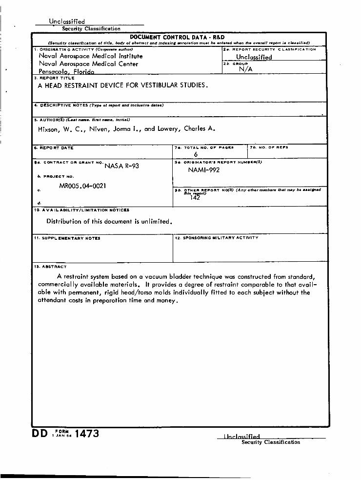
A restraint system based on a vacuum bladder technique was constructed from standard, commercially available materials. It provides a degree o f restraint comparable to that avail- able with permanent, rigid head/torso molds individually fitted to each subject without the attendant cost in preparation time and money.
INTRODUCTION
I -
t '
Of various methods used in vestibular experimentation to hold the head in some fixed orientation, the bite-bar for human subjects and tooth-clamp assembly for animal subjects have probably provided the highest degree of rigid constraint for the head. These methods are, however, unusable, or at least undesirable, in a variety of experimental situations, e.g., those in which continuous voice communications are essential, those in which severe motion sickness and the aspiration of vomitus may occur, and in linear oscillation in which device mal- function may produce impact. The bite-bar has additional disadvantages in that its efficacy i s dependent upon the cooperation of the subiect; inadequate pressure may permit head movement and excessive pressure may p d u c e f i d e x i s e 3r srtifscts to contaminate the recoding of corneo-retinal potentials or similar electrophysiological indices.
When such considerations have forbidden the use of the bite-bar method with our human subjects, we have sometimes resorted to standard U. S. Navy aviation helmets with adjustable head liners and chin straps or to individually fitted head and torso molds fabricated from plaster- of-paris or polyester impregnated glass cloth. The latter technique provides excellent restraint, but i t s usefulness i s limited by the time and cost required for the development of a separate mold for each subject; it i s not at a l l practical for single, brief tests and, even in long or repeated applications, restricted by the number of subjects which can be conveniently handled.
It i s for such reasons as these, probably, that we have received numerous requests from vestibular investigators for a brief technical description of a simple vacuum bag restraint system developed for use with our rotating devices. The basic principle involves the use of atmospheric pressure to force a flexible, airtight bladder f i l l ed with solid particles to become rigid when evacuated. The flexibility permits the bladder to be molded to the configuration of any object, such as the head, which i s to be secured in one position. The rigidity i s maintained as long as the vacuum i s intact. The principle i s not original with us, however. Indeed, it i s our under- standing that similar procedures have had long-time industrial application in vacuum molding, although we are unable to cite any specific instance of such use. A brief description of the materials and methods used in the application of the system in our laboratory follows.
MATERIALS
The primary elements of the vacuum bag restraint system are two rubber bladders, an inflating needle and tubing, a vacuum pump, and 6 pounds of plostic granules (see l i s t of mate- rials). The bladders are standard ones of the type used in boxers' striking bags and are available in any sporting goods store. Their chief advantages are availability, low cost, and adequate flexibil i ty for molding to shape, coupled with sturdiness to resist wear and handling.
The inflating needle i s likewise available in any sporting goods store. The tubing i s standard, 3/8-inch, gum-rubber laboratory tubing; actually the ohly requirement i s that i t be able to resist evacuation without collapsing. The vacuum pump i s of the standard diaphragm type available in most laboratories.
The plastic granules are used to create a buffer to fil l the bladders to facilitate molding and to increase rigidity. They are of the type called "cooking crystals," used by hobbyists for molding plastic objects and are readily available in most hobby supply stores. They appear to be made from a roughly formed plastic rod of about 1/16-inch average diameter and are broken into irregular 1/2O-to-1/IO-inch segments. Their small size lends itself to ready shaping of the bladder, and the irregularities in shape promote interlocking for rigidity when the bladder i s evacuated.
1
METHOD
In the actual preparation of the restraint assembly, each bladder i s f i l led with 3 pounds (approximately 1-1/2 quarts) of granules through a small, circular hole made in one side. After the fi l l ing i s completed, the hole i s sealed with an ordinary, automobile inner-tube cold patch. The bladder i s then evacuated far about 30 seconds by means of the inflating. needle connected by the tubing to a vacuum pump. With the inflating needle removed, the evacuated bladder i s quite rigid and usually maintains its shape well for at least twelve hours. In this respect, leak- age at the bladder valve may occur i f a small granule becomes lodged within the valve mecha- nism. This problem can usually be corrected by applying a small positive pressure to the bladder, resulting in i t s partial inflation.
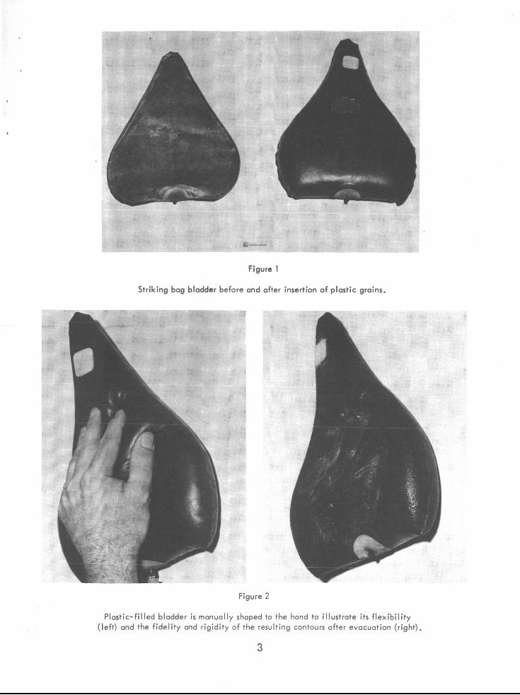
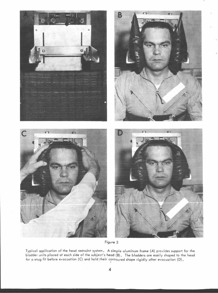
A photograph of a bladder before and after insertion o f the plastic grains i s shown in Figure 1. In Figure 2 a photograph of a bladder being manually shaped to the contours of a hand i s shown at the left; the resulting contours being rigidly held after evacuation are shown at the right. The specific application o f the method in one device i s shown in the photographs presented in Figure 3. An angle-iron support for the bladder assembly was attached to the chair as shown at the upper left. The bladder assembly i s then placed between this bracket and the head as shown at the upper right. The experimenter manually compresses and forms the bladder assembly between the head and the bracket as shown at the lower left and then evacuates the bladder by means o f a foot-operated switch controlling the vacuum pump. After approximately sixty seconds, the bladders are rigid and the head restraint i s complete as shown at the lower right.
The vacuum bag restraint system i s adaptable to fixing the orientation of the head, torso, and/or limbs of any human or animal subject. Obviously improvements could be made in materi- als, e.g., more flexible casing and technique, e.g., precision cutting and assembly of patterns to improve the basic f i t of the bladder or to leave access openings where desired. The above description i s meant only to show how commercially available materials of low cost and simple modification procedures can be used to provide a restraint system equal to or better than most of the methods currently in use.
LIST OF MATERIALS
1. Striking bag bladder, two Kantleek Model SR 1545-R (Seamless Rubber Company, New Haven, Connecticut)
2. Plastic Cooking Crystals, 6 pounds (available in hobby supply stores or from Southwest Hobbies Inc., Wichita Falls, Texas)
3. Air Pump, pressure-vacuum, motor driven, 0-30 inches of mercury (Model 1-093-5V1 , Fisher Scientific Co., U. S. A.)
2
Figure 1
Striking bag bladder before and after insertion of plastic grains.
Figure 2
Plastic-filled bladder i s manually shaped to the hand to illustrate its flexibility (left) and the fidelity and rigidity of the resulting contours after evacuation (right).
3
" - 1
?
,-T . - i
- --e- ----- - -. I
Figure 3
Typical application of the head restraint system. A simple aluminum frame (A) provides support for the bladder units placed at each side of the subject's head (B). The bladders are easily shaped to the head for a snug fit before evacuation (C) and hold .their contoured shape rigidly after evacuation (D).
4
Unc I ossified Securitv Classification
ORIGINATIN G A C T I V I T Y (Corporete author)
Naval Aerospace Medical Institute
Pensacola. Florida Naval Aerospace Medical Center
2a REPORT S E C U R I T Y C L A S S I F I C A T I O N
Unc I ass i f ied 2 b G R O U P
N/A
I. DESCRIPTIVE NOTES (Type of report a d lncluaive date.)
~~~
I. REP0 RT DATE 7 9 . T O T A L N O . O F P A G E S
6
I. AUTHOR(S) (Laat n m e . f l n t name. ini t ia l )
76. N O . O F R E P S
Hixson, W. C., Niven, Jorma I., and Lowery, Charles A.
1. SUPPLEMENTARY NOTES 12. SPONSORING MIL ITARY ACTIVITY
MR005.04-002 1 C. Ob. O T H E R R E P O R T NO(S) ( A n y other number. that may bo aaaldnad
hi. N It) 1 4!?
d.
0. A V A ILABILlTY/LIMITATION NOTICES I
Distribution of this document i s unlimited.
1
3. ABSTRACT
A restraint system based on a vacuum bladder technique was constructed from standard, commercially available materials. It provides a degree of restraint comparable to that avail- able with permanent, rigid head/torso molds individually fitted to each subject without the attendant costs in preparation time and money.
Llnr.lnPzrfld .. Security Classification
Security Classification 14
K E Y WORDS
Restraint systems I Vestibular studies I
INSTRUCTIONS 1. ORIGINATING ACTIVITY Enter the name and address of the contractor, subcontractor, grantee, Department of De. fense activity or other organization (corporate author) issuing the report. 2.2. REPORT SECUWTY CLASSIFICATION Enter the o v e r all security classification of the report. Indicate whether “Restricted Data” i s included Marking is to be in acco rd ance with appropriate security regulations. 26. GROUP Automatic downgrading i s specified in DoD Di- rective 5200.10 and Armed Forces Industrial Manual. Enter the group number. Also, w k n applicable. show that optional markings have been used for Group 3 and Group 4 as author- ized. 3. REPORT T I T L E Enter the complete report t i t le i n all capital letters. T i t l e s in all cases should be unclassified. If a meaningful t i t le CaMOt be selected without classifica- tion, show title classification in all capi ta ls in parenthesis immediately following the title. 4. DESCRIPTIVE NOTES If appropriate, enter the type of report, e.g., interim, progress, summary, annual, or final. Give the inclusive dates when a specific reporting period i s covered. 5. AUTHOR@): Enter the name(s) of author(s) as shown on or in the report. If military, show rank and branch of service. The name of the principal author is an ahsolute minimum requirement. 6. REPORT DATE Enter the date of the report a s day. month, year; or month, year. If more than one date appears on the report, u se date of publication. 7a. TOTAL NUMBER O F PAGES The total page count should follow normal pagination procedures, Le., enter the number of pages containing information. 7b. NUMBER O F REFERENCES: Enter the total number of references cited in the report. 8e. CONTRACT OR GRANT NUMBER: If appropriate, enter the applicable number of the contract or grant under which the report was written. ab, %, & 8d. PROJECT NUMBER. Enter the appropriate military department identification, such as project number, subproject number, system numbers, task number, etc. 9s. ORIGINATOR’S REPORT NUMBER(S): Enter the offi- cial report number by which the document will b e identified and controlled by the originating activity. This number must b e unlque to thls report. 96. OTHER REPORT NUMBER(S): If t he report has been assigned any other report numbers (either by the originator o r by the sponsor), a lso enter this number(8). 10. AVAILABILITY/LIMITATION NOTICES Enter any l i m itations on further disseminstion of the report, other than thou,
Entei l a s t name, first name, middle initial.
imposed by security classification, using standard statements such as:
(1) “Qualified requesters may obtain copies of t h i s report from D D C ”
( 2 ) “Foreign announcement and dissemination of this report by DDC is not authorized”
(3) “U. S. Government agencies may obtain copies of this report directly from DDC. users shal l request through
Other qualified DDC
(4) “U. S. military agencies may obtain copies of this report directly from DDC Other qualified use r s shall request through
(5) “All distribution of this report i s controlled Qual- ified DDC users shall request through
If the report has been furnished to the Office of Technical Services, Department of Commerce, for s a l e to the public, indi- c a t e this fact and enter the price, i f known. It SUPPLEMENTARY NOTES: Use for additional e x p l a n e tory notes. 12. SPONSORING MILITARY ACTIVITY Enter the name of the departmental project office or laboratory sponsoring ( P a r ing for) t he research and development Include address. 13. ABSTRACT: Enter an abstract giving a brief and factual summary of the document indicative of the report, even though i t may a l so appear elsewhere in the body of the technical re- port. If additional space is required, a continuation shee t she be attached.
It is highly desirable that the abstract of c lass i f ied repod be unclassified. Each paragraph of the abstract shal l end wit1 an indication of the military security c lassi f icat ion of the in- formation in the paragraph, represented as (Ts). (s), (C) . o r (U
There i s no limitation on the length of the abstract . How- ever, the suggested length is from 1 5 0 to 2 2 5 words.
14. KEY WORDS: Key words s r e technically meaningful term! or short phrases that characterize a report and may be used a s index e n t d e s for cataloging the report. se lected SO that no security classification is requied. Identi. f iers. such a s equipment model designation, trade name, milits project code name. geographic location, may be used a s key words but will b e followed by an indication of technical con- text. The assignment of l inks, d e s . and weights is optional.