16
— DISTRIBUTOR MIGRATION GUIDE Spectra ™ to SACE ® Tmax ® XT molded case circuit breakers

—DISTRIBUTOR MIGR ATION GUIDE
Spectra™ to SACE® Tmax® XT molded case circuit breakers

B1 copy starts here
B2 copy starts here
B3 copy starts here
Save money by selecting only what you need for your application:• Thermomagnetic trip units up to 800 A• Advanced features and protections• Embedded functionalities and accessories that help reduce
the number of external components• 10+ native communications protocols• Connectivity to ABB Ability™ Energy and Asset Manager
With seven frame sizes and a comprehensive trip unit offering, SACE Tmax XT MCCBs are designed for flexibility, integration and connectivity. Select and order the right products for your application with this quick reference table.
2 S PEC TR A™ TO S ACE ® TM A X® X T M O LD E D C A S E CI RCU IT B R E A K E R S
—SACE® Tmax® XT overviewBreak new ground
Help make your business more competitive with an innovative MCCB that allows you and your customer to save costs and time, from stocking to execution.
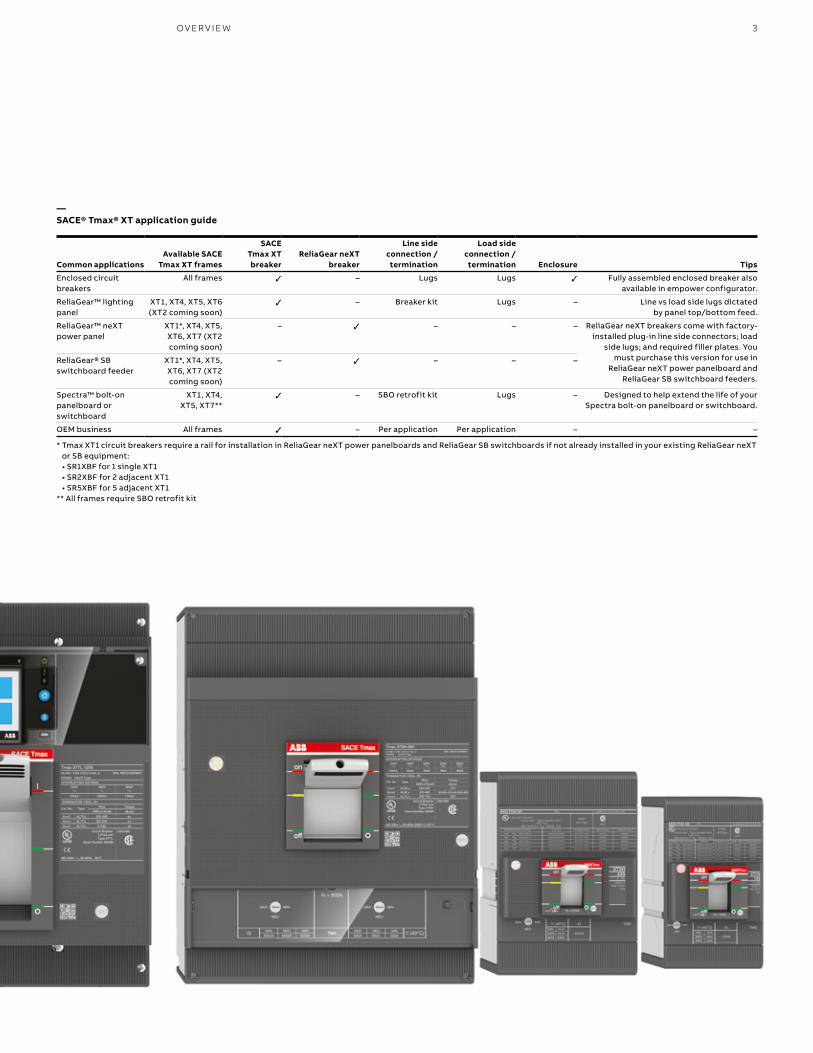
—SACE® Tmax® XT application guide
Common applicationsAvailable SACE
Tmax XT frames
SACE Tmax XT breaker
ReliaGear neXT breaker
Line side connection / termination
Load side connection / termination Enclosure Tips
Enclosed circuit breakers
All frames ✓ – Lugs Lugs ✓ Fully assembled enclosed breaker also available in empower configurator.
ReliaGear™ lighting panel
XT1, XT4, XT5, XT6 (XT2 coming soon)
✓ – Breaker kit Lugs – Line vs load side lugs dictated by panel top/bottom feed.
ReliaGear™ neXT power panel
XT1*, XT4, XT5, XT6, XT7 (XT2 coming soon)
– ✓ – – – ReliaGear neXT breakers come with factory- installed plug-in line side connectors; load
side lugs; and required filler plates. You must purchase this version for use in
ReliaGear neXT power panelboard and ReliaGear SB switchboard feeders.
ReliaGear® SB switchboard feeder
XT1*, XT4, XT5, XT6, XT7 (XT2 coming soon)
– ✓ – – –
Spectra™ bolt-on panelboard or switchboard
XT1, XT4, XT5, XT7**
✓ – SBO retrofit kit Lugs – Designed to help extend the life of your Spectra bolt-on panelboard or switchboard.
OEM business All frames ✓ – Per application Per application – –
* Tmax XT1 circuit breakers require a rail for installation in ReliaGear neXT power panelboards and ReliaGear SB switchboards if not already installed in your existing ReliaGear neXT or SB equipment: • SR1XBF for 1 single XT1 • SR2XBF for 2 adjacent XT1 • SR5XBF for 5 adjacent XT1
** All frames require SBO retrofit kit
3OV ER V I E W
B1 copy starts here
B2 copy starts here
B3 copy starts here
4 S PEC TR A™ TO S ACE ® TM A X® X T M O LD E D C A S E CI RCU IT B R E A K E R S
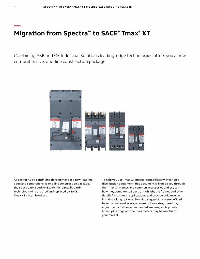
—Migration from Spectra™ to SACE® Tmax® XT
Combining ABB and GE Industrial Solutions leading-edge technologies offers you a new, comprehensive, one-line construction package.
As part of ABB's continuing development of a new, leading-edge and comprehensive one-line construction package, the Spectra RMS and RMS with microEntelliGuard® technology will be retired and replaced by SACE Tmax XT circuit breakers.
To help you use Tmax XT breaker capabilities within ABB's distribution equipment, this document will guide you through the Tmax XT frames and common accessories and explain how they compare to Spectra; highlight the frames and other details for common applications; and provide guidance on initial stocking options. Stocking suggestions were defined based on national average consumption rates; therefore, adjustments to the recommended amperages, trip units, interrupt ratings or other parameters may be needed for your market.

5M I G R ATI O N PATH
—Selecting the right SACE® Tmax® XT frame based on your Spectra™ frameSelect what you need, skip what you don't
Most economical path(Thermomagnetic trip units
and dedicated 480 V AC frames XT1 and XT3)
Notes: Always consider which rating plug you would use with Spectra in your application. There may be opportunities to reduce a frame size with SACE Tmax XT.
SE 150 (125 A and below)
SF 250 A
SG 600 A
XT1125 A
XT3225 A
XT4250 A
XT2125 A
XT5600 A
XT6800 A
XT71200 A
SK 1200 A
High-end features and adjustability path
(Basic and advanced electronic trip units on 600 V AC frames
with increased interrupt rating capabilities)
XT5600 A
SE 150 (above 125 A)

B1 copy starts here
B2 copy starts here
B3 copy starts here
6 S PEC TR A™ TO S ACE ® TM A X® X T M O LD E D C A S E CI RCU IT B R E A K E R S
—SACE® Tmax® XT circuit breakersStocking strategiesThe electrical distribution market can be very competitive. It takes the right balance of value, inventory cost and customer service to be successful. To help you succeed in the market you serve, following are different paths for stocking strategies from which to choose.
Competitive price-focused stocking strategyPros: Most competitive price to market circuit breakers. Overall reduction in the number of stocking part numbers (SKUs) compared to Spectra breakers and rating plugs. Cons: Increased number of full breaker frames means slightly more shelf space than Spectra breakers and rating plugs.
—Suggested SACE Tmax XT stock to support ReliaGear™ lighting panelboards, enclosed circuit breakers, enclosed starters and control products along with OEM business, Spectra™ bolt-on power panelboards and switchboards
Catalog number1
Int. rating2 (kA) at 480 V AC Rated current (A) Trip unit3
Overload (L) adjustability3
Inventory carrying cost reference
XT1HU3015AFF000XXX 65 15 TMF Non-adjustable $
XT1HU3020AFF000XXX 65 20 TMF Non-adjustable $
XT1HU3025AFF000XXX 65 25 TMF Non-adjustable $
XT1HU3030AFF000XXX 65 30 TMF Non-adjustable $
XT1HU3035AFF000XXX 65 35 TMF Non-adjustable $
XT1HU3040AFF000XXX 65 40 TMF Non-adjustable $
XT1HU3045AFF000XXX 65 45 TMF Non-adjustable $
XT1HU3050AFF000XXX 65 50 TMF Non-adjustable $
XT1HU3060AFF000XXX 65 60 TMF Non-adjustable $
XT1HU3070AFF000XXX 65 70 TMF Non-adjustable $
XT1HU3080AFF000XXX 65 80 TMF Non-adjustable $
XT1HU3090AFF000XXX 65 90 TMF Non-adjustable $
XT1HU3100AFF000XXX 65 100 TMF Non-adjustable $
XT1HU3125AFF000XXX 65 125 TMF Non-adjustable $
XT4HU3150AFF000XXX 65 150 TMF Non-adjustable $
XT4HU3175AFF000XXX 65 175 TMF Non-adjustable $
XT4HU3200AFF000XXX 65 200 TMF Non-adjustable $
XT4HU3225AFF000XXX 65 225 TMF Non-adjustable $
XT4HU3250AFF000XXX 65 250 TMF Non-adjustable $
XT5HU340ABFF000XXX 65 400 TMA 280…400 A / via rotary switches $
XT5HU360BBFF000XXX 65 600 TMA 420…600 A / via rotary switches $
XT6HU3800BFF000XXX 65 800 TMA 560…800 A / via rotary switches $
XT7HU312EQFF940XXX4 65 1200 Ekip Touch LSIG 480…1200 A / via touch screen $$$
1 Breakers do not include line/load connections. Please see table on page 3 outlining suggested connections per application 2 65 kA at 480 V AC has been selected to align with the most commonly ordered Spectra across the USA. If your specific needs require a higher or lower interrupt rating, please update
the fourth digit from "H" to reflect the desired level, as explained in Table 4 on page 143 For more details on trip unit features and adjustability, please refer to “SACE Tmax XT range trip unit capabilities” table on page 12 or SACE Tmax XT Technical Catalog4 RELT module and 24–48 V DC power supply already included. 110–240 V AC/DC power supply also available; please refer to empower configurator

7S TO CK IN G S TR ATEG IE S
—Suggested ReliaGear neXT breaker stock to support ReliaGear neXT power panelboards and ReliaGear SB switchboards
Catalog numberInt. rating1 (kA)
at 480 V AC Rated current (A) Trip unit2
Overload (L) adjustability2
Inventory carrying cost reference
XT1HU3015AYD000XXX 65 15 TMF Non-adjustable $
XT1HU3020AYD000XXX 65 20 TMF Non-adjustable $
XT1HU3025AYD000XXX 65 25 TMF Non-adjustable $
XT1HU3030AYD000XXX 65 30 TMF Non-adjustable $
XT1HU3035AYD000XXX 65 35 TMF Non-adjustable $
XT1HU3040AYD000XXX 65 40 TMF Non-adjustable $
XT1HU3045AYD000XXX 65 45 TMF Non-adjustable $
XT1HU3050AYD000XXX 65 50 TMF Non-adjustable $
XT1HU3060AYD000XXX 65 60 TMF Non-adjustable $
XT1HU3070AYD000XXX 65 70 TMF Non-adjustable $
XT1HU3080AYD000XXX 65 80 TMF Non-adjustable $
XT1HU3090AYD000XXX 65 90 TMF Non-adjustable $
XT1HU3100AYD000XXX 65 100 TMF Non-adjustable $
XT4HU3150BYJ000XXX 65 150 TMA 105…150 A / via rotary switches $$
XT4HU3250BYL000XXX 65 250 TMA 175…250 A / via rotary switches $$
XT5HU340ABYN000XXX 65 400 TMA 280…400 A / via rotary switches $
XT5HU360BBYN000XXX 65 600 TMA 420…600 A / via rotary switches $
XT7HU380CFYX000XXX 65 800 Ekip DIP LSI 320…800 A / via DIP switches $$
XT7HU312EPYX940XXX3 65 1200 Ekip Touch LSI 480…1200 A / via touch screen $$$
1 65 kA at 480 V AC has been selected to align with the most commonly ordered Spectra across the USA. If your specific needs require a higher or lower interrupt rating, please update the fourth digit from "H" to reflect the desired level, as explained in Table 4 on page 14
2 For more details on trip unit features and adjustability, please refer to “SACE Tmax XT range trip unit capabilities” table on page 12 or SACE Tmax XT Technical Catalog3 RELT module and 24–48 V DC power supply already included. 110–240 V AC/DC power supply also available; please refer to empower configurator
—ReliaGear neXT breaker
—SACE Tmax XT breaker
B1 copy starts here
B2 copy starts here
B3 copy starts here
8 S PEC TR A™ TO S ACE ® TM A X® X T M O LD E D C A S E CI RCU IT B R E A K E R S
—SACE® Tmax® XT circuit breakersStocking strategies
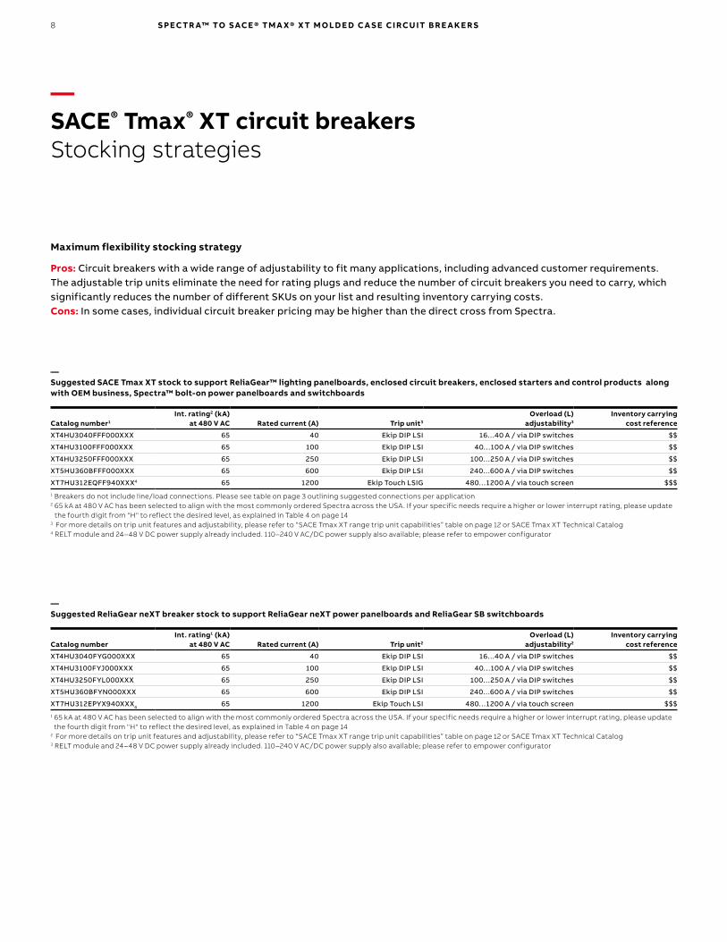
Maximum flexibility stocking strategy
Pros: Circuit breakers with a wide range of adjustability to fit many applications, including advanced customer requirements. The adjustable trip units eliminate the need for rating plugs and reduce the number of circuit breakers you need to carry, which significantly reduces the number of different SKUs on your list and resulting inventory carrying costs.Cons: In some cases, individual circuit breaker pricing may be higher than the direct cross from Spectra.
—Suggested SACE Tmax XT stock to support ReliaGear™ lighting panelboards, enclosed circuit breakers, enclosed starters and control products along with OEM business, Spectra™ bolt-on power panelboards and switchboards
Catalog number1
Int. rating2 (kA) at 480 V AC Rated current (A) Trip unit3
Overload (L) adjustability3
Inventory carrying cost reference
XT4HU3040FFF000XXX 65 40 Ekip DIP LSI 16…40 A / via DIP switches $$
XT4HU3100FFF000XXX 65 100 Ekip DIP LSI 40…100 A / via DIP switches $$
XT4HU3250FFF000XXX 65 250 Ekip DIP LSI 100…250 A / via DIP switches $$
XT5HU360BFFF000XXX 65 600 Ekip DIP LSI 240…600 A / via DIP switches $$
XT7HU312EQFF940XXX4 65 1200 Ekip Touch LSIG 480…1200 A / via touch screen $$$
1 Breakers do not include line/load connections. Please see table on page 3 outlining suggested connections per application 2 65 kA at 480 V AC has been selected to align with the most commonly ordered Spectra across the USA. If your specific needs require a higher or lower interrupt rating, please update
the fourth digit from "H" to reflect the desired level, as explained in Table 4 on page 143 For more details on trip unit features and adjustability, please refer to “SACE Tmax XT range trip unit capabilities” table on page 12 or SACE Tmax XT Technical Catalog4 RELT module and 24–48 V DC power supply already included. 110–240 V AC/DC power supply also available; please refer to empower configurator
—Suggested ReliaGear neXT breaker stock to support ReliaGear neXT power panelboards and ReliaGear SB switchboards
Catalog numberInt. rating1 (kA)
at 480 V AC Rated current (A) Trip unit2
Overload (L) adjustability2
Inventory carrying cost reference
XT4HU3040FYG000XXX 65 40 Ekip DIP LSI 16…40 A / via DIP switches $$
XT4HU3100FYJ000XXX 65 100 Ekip DIP LSI 40…100 A / via DIP switches $$
XT4HU3250FYL000XXX 65 250 Ekip DIP LSI 100…250 A / via DIP switches $$
XT5HU360BFYN000XXX 65 600 Ekip DIP LSI 240…600 A / via DIP switches $$
XT7HU312EPYX940XXX4 65 1200 Ekip Touch LSI 480…1200 A / via touch screen $$$
1 65 kA at 480 V AC has been selected to align with the most commonly ordered Spectra across the USA. If your specific needs require a higher or lower interrupt rating, please update the fourth digit from "H" to reflect the desired level, as explained in Table 4 on page 14
2 For more details on trip unit features and adjustability, please refer to “SACE Tmax XT range trip unit capabilities” table on page 12 or SACE Tmax XT Technical Catalog3 RELT module and 24–48 V DC power supply already included. 110–240 V AC/DC power supply also available; please refer to empower configurator
9S TO CK IN G S TR ATEG IE S
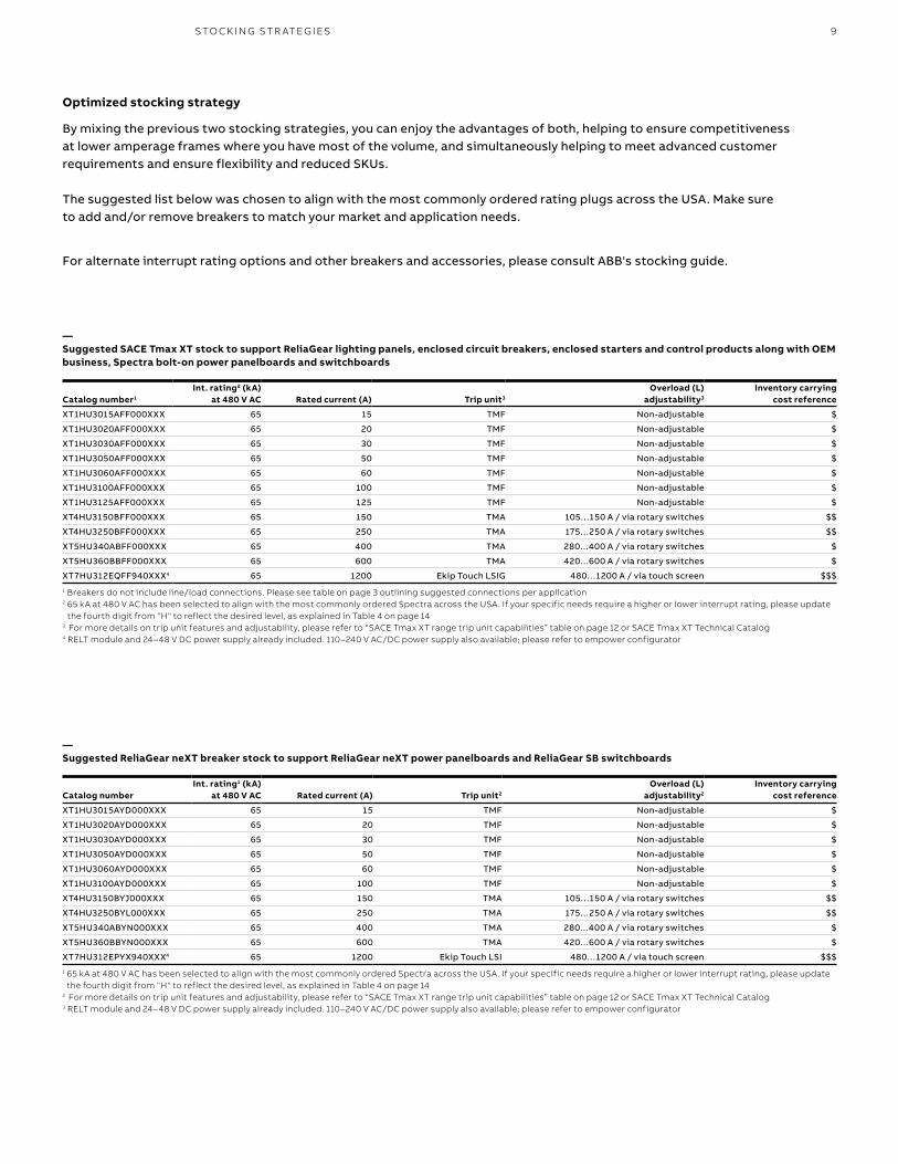
Optimized stocking strategy
By mixing the previous two stocking strategies, you can enjoy the advantages of both, helping to ensure competitiveness at lower amperage frames where you have most of the volume, and simultaneously helping to meet advanced customer requirements and ensure flexibility and reduced SKUs.
The suggested list below was chosen to align with the most commonly ordered rating plugs across the USA. Make sure to add and/or remove breakers to match your market and application needs.
For alternate interrupt rating options and other breakers and accessories, please consult ABB's stocking guide.
—Suggested SACE Tmax XT stock to support ReliaGear lighting panels, enclosed circuit breakers, enclosed starters and control products along with OEM business, Spectra bolt-on power panelboards and switchboards
Catalog number1
Int. rating2 (kA) at 480 V AC Rated current (A) Trip unit3
Overload (L) adjustability3
Inventory carrying cost reference
XT1HU3015AFF000XXX 65 15 TMF Non-adjustable $
XT1HU3020AFF000XXX 65 20 TMF Non-adjustable $
XT1HU3030AFF000XXX 65 30 TMF Non-adjustable $
XT1HU3050AFF000XXX 65 50 TMF Non-adjustable $
XT1HU3060AFF000XXX 65 60 TMF Non-adjustable $
XT1HU3100AFF000XXX 65 100 TMF Non-adjustable $
XT1HU3125AFF000XXX 65 125 TMF Non-adjustable $
XT4HU3150BFF000XXX 65 150 TMA 105…150 A / via rotary switches $$
XT4HU3250BFF000XXX 65 250 TMA 175…250 A / via rotary switches $$
XT5HU340ABFF000XXX 65 400 TMA 280…400 A / via rotary switches $
XT5HU360BBFF000XXX 65 600 TMA 420…600 A / via rotary switches $
XT7HU312EQFF940XXX4 65 1200 Ekip Touch LSIG 480…1200 A / via touch screen $$$
1 Breakers do not include line/load connections. Please see table on page 3 outlining suggested connections per application 2 65 kA at 480 V AC has been selected to align with the most commonly ordered Spectra across the USA. If your specific needs require a higher or lower interrupt rating, please update
the fourth digit from "H" to reflect the desired level, as explained in Table 4 on page 143 For more details on trip unit features and adjustability, please refer to “SACE Tmax XT range trip unit capabilities” table on page 12 or SACE Tmax XT Technical Catalog4 RELT module and 24–48 V DC power supply already included. 110–240 V AC/DC power supply also available; please refer to empower configurator
—Suggested ReliaGear neXT breaker stock to support ReliaGear neXT power panelboards and ReliaGear SB switchboards
Catalog numberInt. rating1 (kA)
at 480 V AC Rated current (A) Trip unit2
Overload (L) adjustability2
Inventory carrying cost reference
XT1HU3015AYD000XXX 65 15 TMF Non-adjustable $
XT1HU3020AYD000XXX 65 20 TMF Non-adjustable $
XT1HU3030AYD000XXX 65 30 TMF Non-adjustable $
XT1HU3050AYD000XXX 65 50 TMF Non-adjustable $
XT1HU3060AYD000XXX 65 60 TMF Non-adjustable $
XT1HU3100AYD000XXX 65 100 TMF Non-adjustable $
XT4HU3150BYJ000XXX 65 150 TMA 105…150 A / via rotary switches $$
XT4HU3250BYL000XXX 65 250 TMA 175…250 A / via rotary switches $$
XT5HU340ABYN000XXX 65 400 TMA 280…400 A / via rotary switches $
XT5HU360BBYN000XXX 65 600 TMA 420…600 A / via rotary switches $
XT7HU312EPYX940XXX4 65 1200 Ekip Touch LSI 480…1200 A / via touch screen $$$
1 65 kA at 480 V AC has been selected to align with the most commonly ordered Spectra across the USA. If your specific needs require a higher or lower interrupt rating, please update the fourth digit from "H" to reflect the desired level, as explained in Table 4 on page 14
2 For more details on trip unit features and adjustability, please refer to “SACE Tmax XT range trip unit capabilities” table on page 12 or SACE Tmax XT Technical Catalog3 RELT module and 24–48 V DC power supply already included. 110–240 V AC/DC power supply also available; please refer to empower configurator
B1 copy starts here
B2 copy starts here
B3 copy starts here
10 S PEC TR A™ TO S ACE ® TM A X® X T M O LD E D C A S E CI RCU IT B R E A K E R S
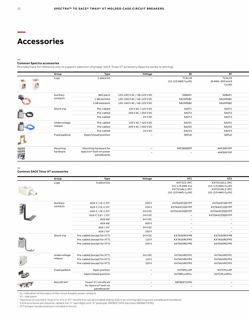
—Accessories
—Common Spectra accessories Provided here for reference only to support selection of proper SACE Tmax XT accessory (Spectra series is retiring).
Group Type Voltage SE SF SG SK
Lugs 1-piece kit – TCAL18 (12–3/0 AWG Cu/Al)
TCAL29 (8 AWG–350 kcmil
Cu/Al)
TCLK365 (2/0 AWG–500 kcmil
Cu/Al) 3-piece kit
TCAL81 (3x 3/0 AWG–500 kcmil Cu/Al)
TCAL125 (4x 250–500 kcmil Cu/Al)
Auxiliary contacts
Bell alarm 120–240 V AC / 48–125 V DC SABAP1 SABAP1 SABAP1 SABAP1
1 AB element 120–240 V AC / 48–125 V DC SAUXPAB1 SAUXPAB1 SAUXPAB1 SAUXPAB1
2 AB elements 120–240 V AC / 48–125 V DC SAUXPAB2 SAUXPAB2 SAUXPAB2 SAUXPAB2
Shunt trip Pre-cabled 120 V AC / 125 V DC SAST1 SAST1 SAST1 SAST1
Pre-cabled 240 V AC / 250 V DC SAST2 SAST2 SAST2 SAST2
Pre-cabled 24 V DC SAST3 SAST3 SAST3 SAST3
Undervoltage release
Pre-cabled 120 V AC / 125 V DC SAUV1 SAUV1 SAUV1 SAUV1
Pre-cabled 240 V AC / 250 V DC SAUV2 SAUV2 SAUV2 SAUV2
Pre-cabled 24 V DC SAUV3 SAUV3 SAUV3 SAUV3
Fixed padlock Open/closed position – SEPLD SEPLD SGPLD SKPLD
Mounting hardware
Mounting hardware for Spectra™ bolt-on power
panelboards
– AMCB6EBFP AMCB6FJFP AMCB6GBFP AMCB3KMFP
– – AMCB3FJFP AMCB3GMFP –
—Common SACE Tmax XT accessories
Group Type Voltage XT1 XT2 XT3 XT4 XT5 XT6 XT7
Lugs 3-piece kits - KXT1CU-3PC (14–1/0 AWG Cu) KXT1CUAL1-3PC
(10–2/0 AWG Cu/Al)
KXT2CUAL1-3PC (14–1/0 AWG Cu/Al)
KXT2CUAL2-3PC (10–2/0 AWG Cu/Al)
KXT3CUAL1-3PC (14–1/0 AWG Cu/Al)
KXT3CUAL2-3PC (4 AWG–300 kcmil Cu/Al)
KXT4CUAL1-3PC (14–1/0 AWG Cu/Al)
KXT4CUAL2-3PC (4 AWG–300 kcmil Cu/Al)
KXT4CUAL3-3PC (3/0 AWG–350 kcmil Cu/Al)
KXT5CUAL350K-3PC (6 AWG–350 kcmil Cu/Al)
KXT5CUAL500K-3PC (250–500 kcmil Cu/Al)
KXT5CUAL2X500K-3PC (2x 2/0 AWG–500 kcmil Cu/Al)
KXT6CUAL2X500K-3PC (2x 250–500 kcmil Cu/Al)
KXT6CUAL3X400K-3PC (3x 2/0 AWG–400 kcmil Cu/Al)
KXT7CUAL4X500K-3PC (4x 4/0 AWG–500 kcmil Cu/Al)
KXT7CUAL3X750KC-3 (3x 500–750 kcmil Cu/Al)
Auxiliary contacts
AUX-C 1 Q +1 SY1 250 V KXTAAXCQSYFP KXTAAXCQSYFP KXTAAXCQSYFP KXTAAXCQSYFP KXTAAXCQSYFP KXTAAXCQSYFP –
AUX-C 2 Q +1 SY1 250 V KXTAAXC2QSYFP KXTAAXC2QSYFP KXTAAXC2QSYFP KXTAAXC2QSYFP KXTAAXC2QSYFP KXTAAXC2QSYFP –
AUX-C 1 Q +1 SY1 24 V DC KXTAAXCDQSYFP KXTAAXCDQSYFP KXTAAXCDQSYFP KXTAAXCDQSYFP KXTAAXCDQSYFP KXTAAXCDQSYFP –
AUX-C 3 Q + 1 SY1 24 V DC – KXTDAXCD3QSYFP – KXTDAXCD3QSYFP KXTDAXCD3QSYFP KXTDAXCD3QSYFP –
AUX 4Q1 24 V DC – – – – – – ZE1AUX4D
AUX 4Q1 400 V – – – – – – ZE1AUX4
AUX 1 SY1 24 V DC – – – – – – ZE1BAD
AUX 1 SY1 250 V – – – – – – ZE1BA
Shunt trip Pre-cabled (except for XT7) 24 V DC KXTASORCFPB KXTASORCFPB KXTASORCFPB KXTASORCFPB KXTASORCFPB KXTASORCFPB ZEASA
Pre-cabled (except for XT7) 110 V KXTASORCFPD KXTASORCFPD KXTASORCFPD KXTASORCFPD KXTFYOCFPD KXTFYOCFPD ZEASE
Pre-cabled (except for XT7) 220 V KXTASORCFPE KXTASORCFPE KXTASORCFPE KXTASORCFPE ZEASG
Undervoltage release
Pre-cabled (except for XT7) 24 V DC KXTAUVRCFP1 KXTAUVRCFP1 KXTAUVRCFP1 KXTAUVRCFP1 KXTFYUC1 KXTFYUC1 ZEAUA
Pre-cabled (except for XT7) 110 V KXTAUVRCFP4 KXTAUVRCFP4 KXTAUVRCFP4 KXTAUVRCFP4 KXTFYUC4 KXTFYUC4 ZEAUE
Pre-cabled (except for XT7) 220 V KXTAUVRCFP5 KXTAUVRCFP5 KXTAUVRCFP5 KXTAUVRCFP5 KXTFYUC5 KXTFYUC5 ZEAUG
Fixed padlock Open position – KXTBPLLOP KXTCPLLOP KXTBPLLOP KXTCPLLOP KXT5PLLOP KXT6PLLOP KXT7PLLOP
Open/closed position – KXTBPLLOPCL KXTCPLLOPCL KXTBPLLOPCL KXTCPLLOPCL KXT5PLLOPLC KXT6PLLOPLC –
Retrofit kit2 Tmax® XT retrofit kit for Spectra™ bolt-on
panelboards3
– SRFB6XT1FPX – – SRFB6XT4FPX SRFB6XT5BFPX – SRFB3XT7MFPX04
– – – – SRFB3XT4FPX SRFB3XT5MFPX – –
1 Q = indication of the status of the circuit-breaker power contacts SY = bell alarm2 Maximum of two SACE Tmax XT4, XT5 or XT7 retrofit kits can be installed side by side in an existing Spectra power panelboard installation3 If Kirk provisions are required, replace the "X" (last digit) with "K" (example: SRFB6XT1FPX becomes SRFB6XT1FPK)4 XT7 breaker handle extension included in this kit
11
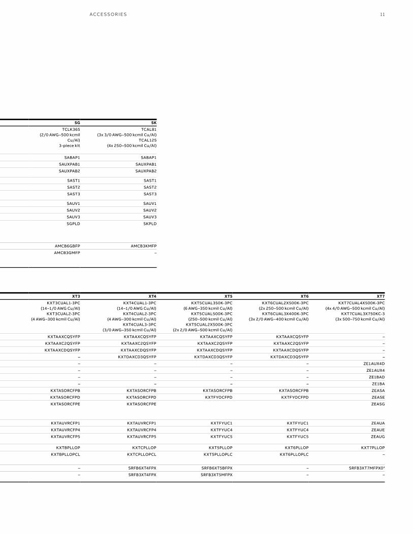
—Common Spectra accessories Provided here for reference only to support selection of proper SACE Tmax XT accessory (Spectra series is retiring).
Group Type Voltage SE SF SG SK
Lugs 1-piece kit – TCAL18 (12–3/0 AWG Cu/Al)
TCAL29 (8 AWG–350 kcmil
Cu/Al)
TCLK365 (2/0 AWG–500 kcmil
Cu/Al) 3-piece kit
TCAL81 (3x 3/0 AWG–500 kcmil Cu/Al)
TCAL125 (4x 250–500 kcmil Cu/Al)
Auxiliary contacts
Bell alarm 120–240 V AC / 48–125 V DC SABAP1 SABAP1 SABAP1 SABAP1
1 AB element 120–240 V AC / 48–125 V DC SAUXPAB1 SAUXPAB1 SAUXPAB1 SAUXPAB1
2 AB elements 120–240 V AC / 48–125 V DC SAUXPAB2 SAUXPAB2 SAUXPAB2 SAUXPAB2
Shunt trip Pre-cabled 120 V AC / 125 V DC SAST1 SAST1 SAST1 SAST1
Pre-cabled 240 V AC / 250 V DC SAST2 SAST2 SAST2 SAST2
Pre-cabled 24 V DC SAST3 SAST3 SAST3 SAST3
Undervoltage release
Pre-cabled 120 V AC / 125 V DC SAUV1 SAUV1 SAUV1 SAUV1
Pre-cabled 240 V AC / 250 V DC SAUV2 SAUV2 SAUV2 SAUV2
Pre-cabled 24 V DC SAUV3 SAUV3 SAUV3 SAUV3
Fixed padlock Open/closed position – SEPLD SEPLD SGPLD SKPLD
Mounting hardware
Mounting hardware for Spectra™ bolt-on power
panelboards
– AMCB6EBFP AMCB6FJFP AMCB6GBFP AMCB3KMFP
– – AMCB3FJFP AMCB3GMFP –
—Common SACE Tmax XT accessories
Group Type Voltage XT1 XT2 XT3 XT4 XT5 XT6 XT7
Lugs 3-piece kits - KXT1CU-3PC (14–1/0 AWG Cu) KXT1CUAL1-3PC
(10–2/0 AWG Cu/Al)
KXT2CUAL1-3PC (14–1/0 AWG Cu/Al)
KXT2CUAL2-3PC (10–2/0 AWG Cu/Al)
KXT3CUAL1-3PC (14–1/0 AWG Cu/Al)
KXT3CUAL2-3PC (4 AWG–300 kcmil Cu/Al)
KXT4CUAL1-3PC (14–1/0 AWG Cu/Al)
KXT4CUAL2-3PC (4 AWG–300 kcmil Cu/Al)
KXT4CUAL3-3PC (3/0 AWG–350 kcmil Cu/Al)
KXT5CUAL350K-3PC (6 AWG–350 kcmil Cu/Al)
KXT5CUAL500K-3PC (250–500 kcmil Cu/Al)
KXT5CUAL2X500K-3PC (2x 2/0 AWG–500 kcmil Cu/Al)
KXT6CUAL2X500K-3PC (2x 250–500 kcmil Cu/Al)
KXT6CUAL3X400K-3PC (3x 2/0 AWG–400 kcmil Cu/Al)
KXT7CUAL4X500K-3PC (4x 4/0 AWG–500 kcmil Cu/Al)
KXT7CUAL3X750KC-3 (3x 500–750 kcmil Cu/Al)
Auxiliary contacts
AUX-C 1 Q +1 SY1 250 V KXTAAXCQSYFP KXTAAXCQSYFP KXTAAXCQSYFP KXTAAXCQSYFP KXTAAXCQSYFP KXTAAXCQSYFP –
AUX-C 2 Q +1 SY1 250 V KXTAAXC2QSYFP KXTAAXC2QSYFP KXTAAXC2QSYFP KXTAAXC2QSYFP KXTAAXC2QSYFP KXTAAXC2QSYFP –
AUX-C 1 Q +1 SY1 24 V DC KXTAAXCDQSYFP KXTAAXCDQSYFP KXTAAXCDQSYFP KXTAAXCDQSYFP KXTAAXCDQSYFP KXTAAXCDQSYFP –
AUX-C 3 Q + 1 SY1 24 V DC – KXTDAXCD3QSYFP – KXTDAXCD3QSYFP KXTDAXCD3QSYFP KXTDAXCD3QSYFP –
AUX 4Q1 24 V DC – – – – – – ZE1AUX4D
AUX 4Q1 400 V – – – – – – ZE1AUX4
AUX 1 SY1 24 V DC – – – – – – ZE1BAD
AUX 1 SY1 250 V – – – – – – ZE1BA
Shunt trip Pre-cabled (except for XT7) 24 V DC KXTASORCFPB KXTASORCFPB KXTASORCFPB KXTASORCFPB KXTASORCFPB KXTASORCFPB ZEASA
Pre-cabled (except for XT7) 110 V KXTASORCFPD KXTASORCFPD KXTASORCFPD KXTASORCFPD KXTFYOCFPD KXTFYOCFPD ZEASE
Pre-cabled (except for XT7) 220 V KXTASORCFPE KXTASORCFPE KXTASORCFPE KXTASORCFPE ZEASG
Undervoltage release
Pre-cabled (except for XT7) 24 V DC KXTAUVRCFP1 KXTAUVRCFP1 KXTAUVRCFP1 KXTAUVRCFP1 KXTFYUC1 KXTFYUC1 ZEAUA
Pre-cabled (except for XT7) 110 V KXTAUVRCFP4 KXTAUVRCFP4 KXTAUVRCFP4 KXTAUVRCFP4 KXTFYUC4 KXTFYUC4 ZEAUE
Pre-cabled (except for XT7) 220 V KXTAUVRCFP5 KXTAUVRCFP5 KXTAUVRCFP5 KXTAUVRCFP5 KXTFYUC5 KXTFYUC5 ZEAUG
Fixed padlock Open position – KXTBPLLOP KXTCPLLOP KXTBPLLOP KXTCPLLOP KXT5PLLOP KXT6PLLOP KXT7PLLOP
Open/closed position – KXTBPLLOPCL KXTCPLLOPCL KXTBPLLOPCL KXTCPLLOPCL KXT5PLLOPLC KXT6PLLOPLC –
Retrofit kit2 Tmax® XT retrofit kit for Spectra™ bolt-on
panelboards3
– SRFB6XT1FPX – – SRFB6XT4FPX SRFB6XT5BFPX – SRFB3XT7MFPX04
– – – – SRFB3XT4FPX SRFB3XT5MFPX – –
1 Q = indication of the status of the circuit-breaker power contacts SY = bell alarm2 Maximum of two SACE Tmax XT4, XT5 or XT7 retrofit kits can be installed side by side in an existing Spectra power panelboard installation3 If Kirk provisions are required, replace the "X" (last digit) with "K" (example: SRFB6XT1FPX becomes SRFB6XT1FPK)4 XT7 breaker handle extension included in this kit
ACCE SSO R IE S

B1 copy starts here
B2 copy starts here
B3 copy starts here—SACE Tmax XT range performance
XT1 XT2 XT3 XT4 XT5 XT6 XT7 SE frame SF frame SG frame SK frameFrame size (A) 125 125 225 250 600 800 1200 Frame size (A) 150 250 600 1200Poles 3, 4 3, 4 3, 4 3, 4 3, 4 3, 4 3, 4 Poles 2, 3 2, 3 2, 3 2, 3Interruptrating (kA)
240 V AC 50, 65, 100 65, 100, 150, 200 50, 65 65, 100, 150, 200 65, 100, 150, 200 65, 100, 200 65, 100, 200 Interrupt ratings (kA) 240 V AC 18, 65, 100, 200 65, 100, 200 65, 100, 200 65, 100, 200480 V AC 25, 35, 65 25, 35, 65, 100, 150,
20025, 35 25, 35, 65, 100, 150,
20035, 50, 65, 100, 150,
20035, 50, 65 50, 65, 100 480 V AC 18, 25, 65, 100 35, 65, 100 35, 65, 100 50, 65, 100
600 V AC – 18, 22, 25, 35, 42 – 18, 22, 25, 50, 65, 100 18, 25, 35, 65, 100 20, 25, 35 25, 50, 65 600 V AC 14, 18, 25 22, 25, 25 25, 65 25, 42, 65Dimensions (in.) (W x D x H)
3-poles breaker
3 x 2.75 x 5.12 3.54 x 3.25 x 5.12 4.13 x 2.75 x 5.90 4.13 x 3.25 x 6.3 5.51 x 4.07 x 8.07 8.27 x 4.07 x 10.55 8.27 x 6.57 x 10.55 Dimensions (in.) (W x D x H)
3-pole breaker 4.12 x 3.38 x 6.31 4.12 x 3.81 x 10.12 5.5 x 3.81 x 10.09 8.25 x 5.5 x 15.5
Packaging 5.04 x 5.63 x 5.31 5.12 x 5.71 x 8.19 6.10 x 7.48 x 7.48 5.71 x 6.61 x 8.27 9.76 x 11.22 x 9.45 12.01 x 14.57 x 11.22 11.02 x 14.17 x 13.78 Packaging Spectra™ RMS 6.63 x 6.19 x 7.13 7.06 x 7.38 x 10.63 9.5 x 8.13 x 11.13 11.19 x 9 x 17Packaging Spectra™ MET – – 9.5 x 8.13 x 15.31 11.19 x 9 x 23.88
Trip units TMF ✓ ✓ ✓ ✓ – – – Trip units RMS ✓ ✓ ✓ ✓
TMA – ✓ – ✓ ✓ ✓ – microEntelliGuard® – – ✓ ✓
Ekip DIP – ✓ – ✓ ✓ ✓ ✓
Ekip Touch
– ✓ – ✓ ✓ – ✓
—SACE Tmax XT range trip units capabilities
Features
Thermomagnetic trip units Electronic trip units
TMF TMAEkip DIP
(LS/I, LIG, LSI and LSIG)Ekip Touch, Touch measuring
and Hi-Touch (LSI and LSIG) Features RMS microEntelliguard®Overload (L) and Instantaneous (I) protection ✓ ✓ ✓ ✓ Overload (L) and Instantaneous (I) protection ✓ ✓
Ground fault protection (G) – – X (with LSIG) X (with LSIG) Ground fault protection (G) – OSelective short circuit protection (S) – – X (with LS/I 1 , LSI or LSIG) ✓ Selective short circuit protection (S) ✓ ✓
L protection adjustability (I1) Fixed 0.7–1 x In* 0.4…1.0 x In 0.4…1.0 x In L protection adjustability (C) As per available rating plugs (RP) 0.5…1.0 x RPSteps of 0.04 (LS/I) or 0.02 (LSI/LSIG) Steps of 0.001 x In Steps of 0.05 x RP
S protection adjustability (I2) 2 – – Off, 1…10 x In Off, 0.6…10 x In S protection adjustability Tracking short-time proportional to I, starting at around 60% x I
Off, 1.5…9.0 x CSteps of 0.5 x In 3 Steps of 0.1 x In Steps of 0.5 x C
I protection adjustability (I3) 2 Fixed 5–10 x In 1…10 x In 1.5…10 x In (15 x In for XT7) I protection adjustability SE: 2.9, 3.7, 4.7, 5.9, 7.7, 9.9 or 12.5 x RP 1 SG: 2.0…10.0 x breaker sensorSteps of 0.5 x In 3 Steps of 0.1 x In SF: 3.0, 3.8, 4.8, 6.0, 7.8 or 10 x RP 1 SK: 2.0…17.0 x breaker sensor
SG: 3.0, 3.8, 4.8, 6.0, 7.8 or 10.1 x RP 1 Steps of 0.5 x breaker sensorSK: 3.1, 3.8, 4.8, 6.1, 8.0 or 10.1 x RP 1
G protection adjustability (I4) 2 – – Off, 0.2, 0.25, 0.45, 0.55, 0.75, 0.80 and 1 x In) Off, 0.1…1 x In G protection adjustability – 0.4…1.0 x breaker sensor0.001 x In Steps of 0.01 x breaker sensor
Communication – – O O Communication – O (Modbus RTU only)Cloud connectivity – – – O Cloud connectivity – –Bluetooth 4
connectivity– – – ✓ Bluetooth 3
connectivity– –
Current measurements – – – ✓ Current measurements – ✓
Voltage, power and energy measurements – – – X (with Ekip Touch measuring) Voltage, power and energy measurements – O 2
Voltage, power and energy measurements and protections
– – – X (with Ekip Hi-Touch) Voltage, power and energy measurements and protections
– –
Embedded functions – – – O Embedded functions – –RELT (reduced energy let-through feature) – – – O RELT (reduced energy let-through feature) – OEvent recorder, contact wear information and self-diagnosis
– – – ✓ Event recorder, contact wear information and self-diagnosis
– –
Legend – Not a possible feature ✓ IncludedO Optional* In = Trip unit sensor1 Either S or I must be selected during comissioning2 Valid for Tmax XT1-6. For Tmax XT7, please refer to Tech Catalog3 4, 5, 6 and 9.5 x In not available4 Bluetooth is a trademark of Bluetooth SIG, Inc.
12 S PEC TR A™ TO S ACE ® TM A X® X T M O LD E D C A S E CI RCU IT B R E A K E R S
—SACE® Tmax® XT MCCBs main characteristics

—Spectra range performance
—SACE Tmax XT range performance
XT1 XT2 XT3 XT4 XT5 XT6 XT7 SE frame SF frame SG frame SK frameFrame size (A) 125 125 225 250 600 800 1200 Frame size (A) 150 250 600 1200Poles 3, 4 3, 4 3, 4 3, 4 3, 4 3, 4 3, 4 Poles 2, 3 2, 3 2, 3 2, 3Interruptrating (kA)
240 V AC 50, 65, 100 65, 100, 150, 200 50, 65 65, 100, 150, 200 65, 100, 150, 200 65, 100, 200 65, 100, 200 Interrupt ratings (kA) 240 V AC 18, 65, 100, 200 65, 100, 200 65, 100, 200 65, 100, 200480 V AC 25, 35, 65 25, 35, 65, 100, 150,
20025, 35 25, 35, 65, 100, 150,
20035, 50, 65, 100, 150,
20035, 50, 65 50, 65, 100 480 V AC 18, 25, 65, 100 35, 65, 100 35, 65, 100 50, 65, 100
600 V AC – 18, 22, 25, 35, 42 – 18, 22, 25, 50, 65, 100 18, 25, 35, 65, 100 20, 25, 35 25, 50, 65 600 V AC 14, 18, 25 22, 25, 25 25, 65 25, 42, 65Dimensions (in.) (W x D x H)
3-poles breaker
3 x 2.75 x 5.12 3.54 x 3.25 x 5.12 4.13 x 2.75 x 5.90 4.13 x 3.25 x 6.3 5.51 x 4.07 x 8.07 8.27 x 4.07 x 10.55 8.27 x 6.57 x 10.55 Dimensions (in.) (W x D x H)
3-pole breaker 4.12 x 3.38 x 6.31 4.12 x 3.81 x 10.12 5.5 x 3.81 x 10.09 8.25 x 5.5 x 15.5
Packaging 5.04 x 5.63 x 5.31 5.12 x 5.71 x 8.19 6.10 x 7.48 x 7.48 5.71 x 6.61 x 8.27 9.76 x 11.22 x 9.45 12.01 x 14.57 x 11.22 11.02 x 14.17 x 13.78 Packaging Spectra™ RMS 6.63 x 6.19 x 7.13 7.06 x 7.38 x 10.63 9.5 x 8.13 x 11.13 11.19 x 9 x 17Packaging Spectra™ MET – – 9.5 x 8.13 x 15.31 11.19 x 9 x 23.88
Trip units TMF ✓ ✓ ✓ ✓ – – – Trip units RMS ✓ ✓ ✓ ✓
TMA – ✓ – ✓ ✓ ✓ – microEntelliGuard® – – ✓ ✓
Ekip DIP – ✓ – ✓ ✓ ✓ ✓
Ekip Touch
– ✓ – ✓ ✓ – ✓
—SACE Tmax XT range trip units capabilities
Features
Thermomagnetic trip units Electronic trip units
TMF TMAEkip DIP
(LS/I, LIG, LSI and LSIG)Ekip Touch, Touch measuring
and Hi-Touch (LSI and LSIG) Features RMS microEntelliguard®Overload (L) and Instantaneous (I) protection ✓ ✓ ✓ ✓ Overload (L) and Instantaneous (I) protection ✓ ✓
Ground fault protection (G) – – X (with LSIG) X (with LSIG) Ground fault protection (G) – OSelective short circuit protection (S) – – X (with LS/I 1 , LSI or LSIG) ✓ Selective short circuit protection (S) ✓ ✓
L protection adjustability (I1) Fixed 0.7–1 x In* 0.4…1.0 x In 0.4…1.0 x In L protection adjustability (C) As per available rating plugs (RP) 0.5…1.0 x RPSteps of 0.04 (LS/I) or 0.02 (LSI/LSIG) Steps of 0.001 x In Steps of 0.05 x RP
S protection adjustability (I2) 2 – – Off, 1…10 x In Off, 0.6…10 x In S protection adjustability Tracking short-time proportional to I, starting at around 60% x I
Off, 1.5…9.0 x CSteps of 0.5 x In 3 Steps of 0.1 x In Steps of 0.5 x C
I protection adjustability (I3) 2 Fixed 5–10 x In 1…10 x In 1.5…10 x In (15 x In for XT7) I protection adjustability SE: 2.9, 3.7, 4.7, 5.9, 7.7, 9.9 or 12.5 x RP 1 SG: 2.0…10.0 x breaker sensorSteps of 0.5 x In 3 Steps of 0.1 x In SF: 3.0, 3.8, 4.8, 6.0, 7.8 or 10 x RP 1 SK: 2.0…17.0 x breaker sensor
SG: 3.0, 3.8, 4.8, 6.0, 7.8 or 10.1 x RP 1 Steps of 0.5 x breaker sensorSK: 3.1, 3.8, 4.8, 6.1, 8.0 or 10.1 x RP 1
G protection adjustability (I4) 2 – – Off, 0.2, 0.25, 0.45, 0.55, 0.75, 0.80 and 1 x In) Off, 0.1…1 x In G protection adjustability – 0.4…1.0 x breaker sensor0.001 x In Steps of 0.01 x breaker sensor
Communication – – O O Communication – O (Modbus RTU only)Cloud connectivity – – – O Cloud connectivity – –Bluetooth 4
connectivity– – – ✓ Bluetooth 3
connectivity– –
Current measurements – – – ✓ Current measurements – ✓
Voltage, power and energy measurements – – – X (with Ekip Touch measuring) Voltage, power and energy measurements – O 2
Voltage, power and energy measurements and protections
– – – X (with Ekip Hi-Touch) Voltage, power and energy measurements and protections
– –
Embedded functions – – – O Embedded functions – –RELT (reduced energy let-through feature) – – – O RELT (reduced energy let-through feature) – OEvent recorder, contact wear information and self-diagnosis
– – – ✓ Event recorder, contact wear information and self-diagnosis
– –
Legend – Not a possible feature ✓ IncludedO Optional* In = Trip unit sensor1 Either S or I must be selected during comissioning2 Valid for Tmax XT1-6. For Tmax XT7, please refer to Tech Catalog3 4, 5, 6 and 9.5 x In not available4 Bluetooth is a trademark of Bluetooth SIG, Inc.
Legend – Not a possible feature✓ IncludedO Optional1 Values may vary depending on rating plug and frame rating2 Proper operation of the advanced metering function requires multiple system accessories including power supplies, voltage conditioners, junction boxes and interconnect cables3 Bluetooth is a trademark of Bluetooth SIG, Inc.
—Spectra trip unit capabilities
13 M A I N CH A R AC TER IS TI C S
—Spectra™ MCCBs main characteristicsFor reference (Spectra is retiring)

B1 copy starts here
B2 copy starts here
B3 copy starts here
14 S PEC TR A™ TO S ACE ® TM A X® X T M O LD E D C A S E CI RCU IT B R E A K E R S
—SACE® Tmax® XT molded case circuit breakersProduct ordering number structure
1 2 3 4 5 6 7 8 9 10 11 12 13 14 15 16 17 18
1 & 2 Version
DigitX T
4 Interrupting ratings – 480 V AC*
Digits XT1 XT2 XT3 XT4 XT5 XT6 XT7
N 25 25 25 25 35 35 –S 35 35 35 35 50 50 50H 65 65 – 65 65 65 65L – 100 – 100 100 – 100V – 150 – 150 150 – –X – 200 – 200 200 – –
5 Standard UL and IEC
Digit
U UL 80%
Q UL 100%
C UL 80% + CCC
D UL 100% + CCC
E IEC only
S IEC 50 °C
3 Frame
Digit1 2 3 4 5 6 7
6 Number of poles
Digit
2 2 Poles
3 3 Poles
4 4 Poles 100%
N 4 Poles 50% (IEC only)
7, 8, 9 Frame amps
XT1–4 XT5–7
Digits Amps Digits Amps
0 1 0 10 2 5 A 250 (XT5)
0 1 5 15 3 0 A 300 (XT5)
0 2 0 20 3 2 A 320 (XT5 IEC1)
0 2 5 25 4 0 A 400 (XT5)
0 3 0 30 5 0 B 500 (XT5)
0 3 5 35 6 0 B 600 (XT5)
0 4 0 40 6 0 0 600 (XT6)
0 4 5 45 6 0 C 600 (XT7)
0 5 0 50 6 3 B 630 (XT5 IEC1)
0 6 0 60 6 3 0 630 (XT6 IEC1)
0 7 0 70 8 0 0 800 (XT6)
0 8 0 80 8 0 C 800 (XT7)
0 9 0 90 1 K 0 1000 (XT6 IEC1)
1 0 0 100 1 0 D 1000 (XT7)
1 1 0 110 1 2 E 1200/1250 (XT7)
1 2 5 125 1 6 F 1600 (XT7 IEC1)
1 5 0 150
1 7 5 175
2 0 0 200
2 2 5 225
2 5 0 250
10 Trip unit
Digit
A TMF/TMD
B TMA
C Ekip DIP LIG
D MCS
E Ekip DIP LS/I
F Ekip DIP LSI
G Ekip DIP LSIG
J Ekip DIP I
K Ekip DIP M-I
L Ekip DIP M-LIU
M MA (MCP)
N TMG
P Ekip Touch LSI
Q Ekip Touch LSIG
R Ekip Touch Measuring LSI
S Ekip Touch Measuring LSIG
T Ekip Hi-Touch LSI
U Ekip Hi-Touch LSIG
W Ekip M Touch LRIU
X Ekip G DIP LS/I
Y Ekip G Touch LSIG
Z Ekip G Hi-Touch LSIG
Accessories digits. For accessorized Tmax XT, please use our empower configurator
X T **
** Must be “Y” for ReliaGear neXT breakers, used in ReliaGear neXT power panelboards and ReliaGear SB switchboards.* For 240 V AC and 600 V AC ratings, refer to Tmax XT UL Technical Catalog.1 IEC only.This ordering code structure is meant for field identification of a SACE Tmax XT. For a breaker selection, please refer to Buylog, Technical Catalog or empower configurator.
15PR O D U C T N U M B ER S TR U C T U R E
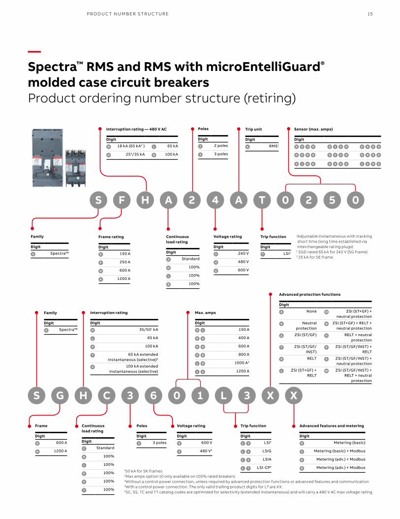
—Spectra™ RMS and RMS with microEntelliGuard®
molded case circuit breakersProduct ordering number structure (retiring)
Family
Digit
S Spectra™
Frame rating
Digit
E 150 A
F 250 A
G 600 A
K 1200 A
Interruption rating — 480 V AC
Digit
D 18 kA (65 kA2 ) L 65 kA
H 253/35 kA R 100 kA
S F 4 TA 2H 2A 5 00
Continuous load rating
Digit
A Standard
H 100%
L 100%
R 100%
Poles
Digit
2 2 poles
3 3 poles
Voltage rating
Digit
2 240 V
4 480 V
6 600 V
Trip unit
Digit
A RMS1
Trip function Digit
T LSI1
Sensor (max. amps) Digit
0 0 3 0 0 1 5 0 0 6 0 0
0 0 6 0 0 2 5 0 0 8 0 0
0 1 0 0 0 4 0 0 1 2 0 0
1 Adjustable instantaneous with tracking short time (long time established via interchangeable rating plugs)
2 SGD rated 65 kA for 240 V (SG frame)3 25 kA for SE frame
S G 6 1C 3H 30 X XL
Family
Digit
S Spectra™
Frame
Digit
G 600 A
K 1200 A
Interruption rating
Digit
H 35/501 kA
L 65 kA
P 100 kA
T 65 kA extended instantaneous (selective)5
S 100 kA extended instantaneous (selective)
Continuous load rating
Digit
C Standard
H 100%
L 100%
P 100%
S 100%
T 100%
Poles
Digit
3 3 poles
Voltage rating
Digit
6 600 V
4 480 V5
Max. amps
Digit
0 1 150 A
0 4 400 A
0 6 600 A
0 8 800 A
1 0 1000 A2
1 2 1200 A
Trip function
Digit
L 3 LSI3
L 4 LSIG
L 5 LSIA
L 7 LSI-CP4
Advanced protection functions
Digit
X None M ZSI (ST+GF) + neutral protection
K Neutral protection
N ZSI (ST+GF) + RELT + neutral protection
Z ZSI (ST/GF) V RELT + neutral protection
T ZSI (ST/GF/INST)
P ZSI (ST/GF/INST) + RELT
R RELT S ZSI (ST/GF/INST) + neutral protection
L ZSI (ST+GF) + RELT
W ZSI (ST/GF/INST) + RELT + neutral
protection
Advanced features and metering
Digit
X Metering (basic)
2 Metering (basic) + Modbus
6 Metering (adv.) + Modbus
8 Metering (adv.) + Modbus150 kA for SK frames2Max amps option 10 only available on 100% rated breakers3Without a control power connection, unless required by advanced protection functions or advanced features and communication4With a control power connection. The only valid trailing product digits for L7 are XX.5SC, SS, TC and TT catalog codes are optimized for selectivity (extended instantaneous) and will carry a 480 V AC max voltage rating

1SX
U21
026
2B0
201
3.2
021
—ABB Inc. 305 Gregson Drive Cary, NC 27511
electrification.us.abb.com
Customer Service: 888-862-3290 [email protected] Monday–Friday, 7am–5:30pm, Central Time
Technical Support: 888-437-3765 Monday–Friday, 7am–5pm, Central Time
—We reserve all rights in this document and in the subject matter and illustrations contained therein. Any reproduction or utilization of its contents – in whole or in parts – is forbidden without prior written consent of ABB Inc. © 2021 ABB Inc. All rights reserved
We reserve the right to make technical changes or modify the contents of this document without prior notice. With regard to purchase orders, the agreed particulars shall prevail. ABB Inc. does not accept any responsibility whatsoever for potential errors or possible lack of information in this document.


