HAL Id: hal-02867784 https://hal.archives-ouvertes.fr/hal-02867784 Submitted on 15 Jun 2020 HAL is a multi-disciplinary open access archive for the deposit and dissemination of sci- entific research documents, whether they are pub- lished or not. The documents may come from teaching and research institutions in France or abroad, or from public or private research centers. L’archive ouverte pluridisciplinaire HAL, est destinée au dépôt et à la diffusion de documents scientifiques de niveau recherche, publiés ou non, émanant des établissements d’enseignement et de recherche français ou étrangers, des laboratoires publics ou privés. Disturbance Rejection Control Strategy of Hybrid Battery/Super Capacitors Power System Based on a Single Converter Yue Zhou, Hussein Obeid, Salah Laghrouche, Mickaël Hilairet, Abdesslem Djerdir To cite this version: Yue Zhou, Hussein Obeid, Salah Laghrouche, Mickaël Hilairet, Abdesslem Djerdir. Disturbance Rejec- tion Control Strategy of Hybrid Battery/Super Capacitors Power System Based on a Single Converter. International Conference on Renewable Energy Research and Application, Nov 2019, Brasov, Roma- nia. hal-02867784
Transcript
HAL Id: hal-02867784https://hal.archives-ouvertes.fr/hal-02867784
Submitted on 15 Jun 2020
HAL is a multi-disciplinary open accessarchive for the deposit and dissemination of sci-entific research documents, whether they are pub-lished or not. The documents may come fromteaching and research institutions in France orabroad, or from public or private research centers.
L’archive ouverte pluridisciplinaire HAL, estdestinée au dépôt et à la diffusion de documentsscientifiques de niveau recherche, publiés ou non,émanant des établissements d’enseignement et derecherche français ou étrangers, des laboratoirespublics ou privés.
Disturbance Rejection Control Strategy of HybridBattery/Super Capacitors Power System Based on a
Single ConverterYue Zhou, Hussein Obeid, Salah Laghrouche, Mickaël Hilairet, Abdesslem
Djerdir
To cite this version:Yue Zhou, Hussein Obeid, Salah Laghrouche, Mickaël Hilairet, Abdesslem Djerdir. Disturbance Rejec-tion Control Strategy of Hybrid Battery/Super Capacitors Power System Based on a Single Converter.International Conference on Renewable Energy Research and Application, Nov 2019, Brasov, Roma-nia. �hal-02867784�
Abstract— This paper proposes a robust control strategy for a
hybrid battery/super capacitors power system with a single
converter. In such systems, it is required to smooth the battery
current considering the load power transient and the current
oscillations of the DC bus delivered by the load in the context of a
hybrid electric vehicle. Furthermore, constraints of all the system
components, i.e. maximum current of the battery and super
capacitors, state of the charge of the super capacitors and battery
temperature should be taken into account. To deal with these
demands, a novel cascaded voltage control loop is proposed. For
the outer voltage loop, an anti-windup proportional integral
controller is used to regulate the super capacitor voltage at its
nominal value. On the other hand, for the inner voltage loop, an
anti-windup super twisting controller is proposed to ensure the
convergence of the DC bus voltage to its reference value while
attenuating the external perturbation. Indeed, the specific feature
of such controller is that it works like a low-pass filter which
leads to attenuate the current oscillations in the DC bus.
Keywords—hybrid power system; anti-windup super twisting
controller; battery; super capacitors; disturbance rejection
I. INTRODUCTION
Over the last decade, environmental pollution and energy shortages have become an increasing concern for the people and the government in many countries. In order to deal with these urgent issues, the adoption of hybrid electric vehicles (HEV) is considered as one of the most hopeful strategies nowadays [1-5]. The research on renewable energy storage system plays a crucial role in hybrid electric vehicles, especially the study on renewable energy sources, such as battery (Bat), super capacitors (SCs), fuel cells, fly wheel and so on [6-8]. Due to the high energy density of Bat and the high power density of SCs, it is significant to integrate both of them into a hybrid electrical system. The main energy source is provided by the Bat while the SCs deal with the load transient disturbance and power peak in sudden operations [9- 11].
Generally, the topologies of hybrid power system are various and the main topologies can be divided into following three categories: fully-active, semi-active and passive [12]. For fully-active topology, there are two DC/DC converters and each converter is connected to a power source. It results in flexible control performance but it costs a lot for expenses. For passive topology, no DC/DC converter is utilized so that it
costs least while it has the lowest controllability. Therefore, in order to obtain an approving balance between the control performance and economy, semi-active topology based on a single converter is adopted in this paper. Moreover, several control strategies have been adopted in hybrid power system previously [13-17]. However, the solution of the disturbance rejection is not considered for a single converter based Bat/ SCs system. Hence, developing a suitable control strategy for rejecting the transient disturbance from the load current and reducing oscillations of the Bat current is vital. As one of popular non-linear controllers, sliding mode controller is a robust controller in the presence of perturbation and uncertainty conditions. Due to this reason, sliding mode controller is an appropriate choice in our case. As one type of sliding mode controllers, super twisting (ST) controller has the feature like a low-pass filter to attenuate the oscillations in the DC bus, so as to be adopted in this paper [18-24].
This paper is organized as following sections: First, in section II, the topology of the hybrid system based on the main sources of Bat and SCs with a single converter is described. Then, the control strategy based on anti-windup ST controller and anti-windup proportional integral (PI) controller, and the current limitation constraints of Bat and SCs are illustrated in section III. Next, in section IV, the simulation results and comparison discussions are presented to validate the effectiveness of the proposed control strategy. Finally, conclusions are presented in section V.
II. HYBRID SYSTEM TOPOLOGY
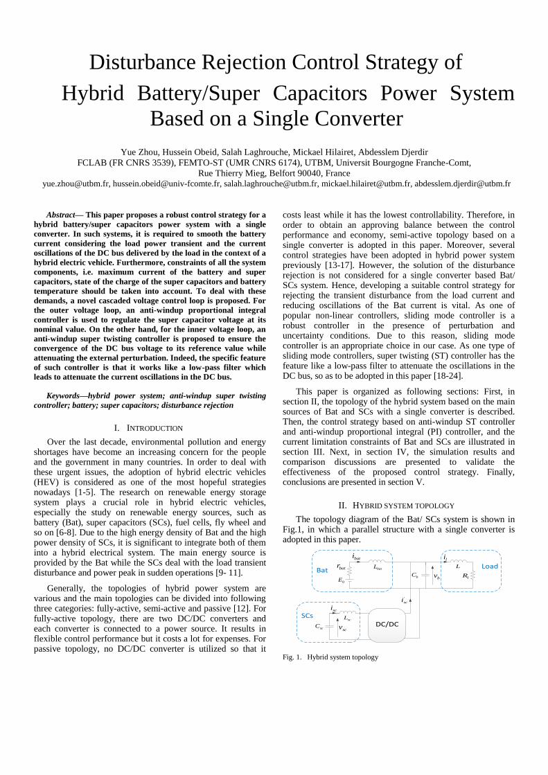
The topology diagram of the Bat/ SCs system is shown in Fig.1, in which a parallel structure with a single converter is adopted in this paper.
As shown in Fig.1, the power sources of this hybrid electrical system consist of the Bat modeled by a voltage source and SCs modeled by a voltage source connected to a pure inductor.
III. CONTROL STRATEGY
A. Description of the Control Structure
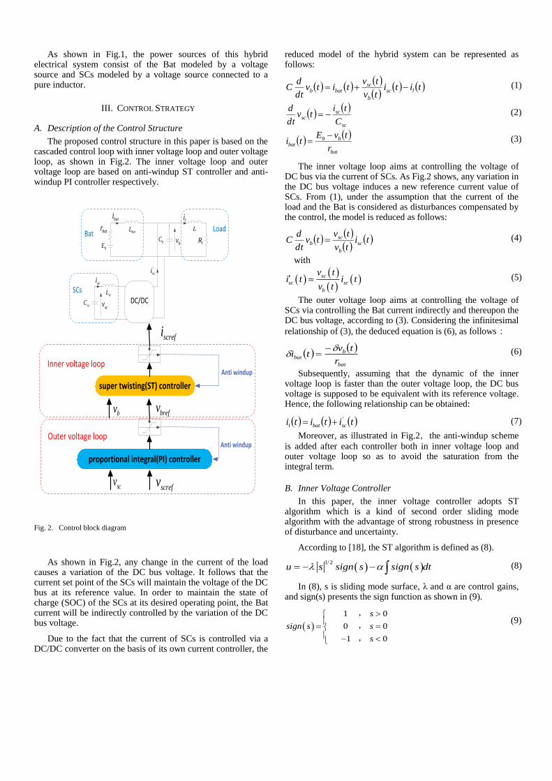
The proposed control structure in this paper is based on the cascaded control loop with inner voltage loop and outer voltage loop, as shown in Fig.2. The inner voltage loop and outer voltage loop are based on anti-windup ST controller and anti-windup PI controller respectively.
proportional integral(PI) controller
super twisting(ST) controller
Anti windup
Anti windup
bv
scv
Inner voltage loop
Outer voltage loop
screfi
brefv
screfv
DC/DC
0E
scC
scL
sci
SCs
BatbC
bv
L
lR
Loadli
'
sci
scv
bati
batrbatL
Fig. 2. Control block diagram
As shown in Fig.2, any change in the current of the load causes a variation of the DC bus voltage. It follows that the current set point of the SCs will maintain the voltage of the DC bus at its reference value. In order to maintain the state of charge (SOC) of the SCs at its desired operating point, the Bat current will be indirectly controlled by the variation of the DC bus voltage.
Due to the fact that the current of SCs is controlled via a DC/DC converter on the basis of its own current controller, the
reduced model of the hybrid system can be represented as follows:
tititv
tvtitv
dt
dC lsc
b
scbatb (1)
sc
scsc
C
titv
dt
d (2)
bat
bbat
r
tvEti
0 (3)
The inner voltage loop aims at controlling the voltage of DC bus via the current of SCs. As Fig.2 shows, any variation in the DC bus voltage induces a new reference current value of SCs. From (1), under the assumption that the current of the load and the Bat is considered as disturbances compensated by the control, the model is reduced as follows:
titv
tvtv
dt
dC sc
b
scb (4)
with
sc
sc sc
b
v ti t i t
v t (5)
The outer voltage loop aims at controlling the voltage of SCs via controlling the Bat current indirectly and thereupon the DC bus voltage, according to (3). Considering the infinitesimal
relationship of (3), the deduced equation is (6), as follows:
bat
bbat
r
tvti
(6)
Subsequently, assuming that the dynamic of the inner voltage loop is faster than the outer voltage loop, the DC bus voltage is supposed to be equivalent with its reference voltage. Hence, the following relationship can be obtained:
tititi scbatl
' (7)
Moreover, as illustrated in Fig.2,the anti-windup scheme
is added after each controller both in inner voltage loop and outer voltage loop so as to avoid the saturation from the integral term.
B. Inner Voltage Controller
In this paper, the inner voltage controller adopts ST algorithm which is a kind of second order sliding mode algorithm with the advantage of strong robustness in presence of disturbance and uncertainty.
According to [18], the ST algorithm is defined as (8).
1/2
u s sign s sign s dt (8)
In (8), s is sliding mode surface, λ and α are control gains, and sign(s) presents the sign function as shown in (9).
1 0
0 0
1 0
s
sign s s
s
,
,
,
(9)
In addition, u is defined as the reference current of SCs in (8), and the sliding mode surface is defined as below:
bref bs v v (10)
Thus, (8) can be represented as follows:
1/2
scref bref b bref b bref bi v v sign v v sign v v dt (11)
C. Outer Voltage Controller
As illustrated in Fig.2, the outer voltage loop is based on PI controller, which is designed as follows:
dtvvkvvkv scscrefiscscrefpbref (12)
In (12), pk and ik are the gains of the proportional and
integral terms respectively.
D. Constraints of Battery and Super Capacitors Pack
1) Limitation of Battery Current: The limitation of Bat
current cannot be implemented directly by the command owing
to the fact that the load is linked to the Bat directly. In order to
limit the Bat current in the security range, the voltage of DC
bus needs to be regulated. Otherwise, the Bat pack may suffer
irreversible damage. The voltage of DC bus is in a bounded range, as shown
below:
_ min _ max,b b bv v v (13)
Within the above fixed interval, in order to limit the current of the Bat in charge and discharge modes, the dynamic thresholds of DC bus reference voltage calculated by the outer voltage loop are defined as follows:
_ min_ _ max_,bref b dyn b dynv v v (14)
During charge mode, if the Bat current reaches its
threshold _ max_bat chai , the maximum dynamic voltage
threshold _ max_b dynv will decrease so as to reduce the absolute
value of Bat current. Similarly, during discharge mode, if the
Bat current reaches the threshold _ max_bat disi , the minimum
dynamic voltage threshold _ min_b dynv will increase
correspondingly.
The above constraints of Bat current can be summarized as (15) and (16), which are integrated in the anti-windup scheme of the outer voltage loop, in order to prevent the saturation of the integral term.
_ max_ _ max_b dyn bref ibat bat bat chav v K i t i (15)
_ min_ _ max_b dyn bref ibat bat bat disv v K i t i (16)
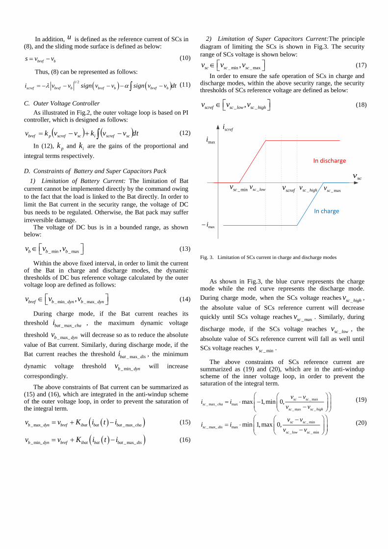
2) Limitation of Super Capacitors Current:The principle
diagram of limiting the SCs is shown in Fig.3. The security
range of SCs voltage is shown below:
_ min _ max,sc sc scv v v (17)
In order to ensure the safe operation of SCs in charge and discharge modes, within the above security range, the security thresholds of SCs reference voltage are defined as below:
_ _,scref sc low sc highv v v (18)
scv
_sc highv_sc lowv_ maxscv_ minscv
maxi
In discharge
In charge
maxi
screfi
screfv
Fig. 3. Limitation of SCs current in charge and discharge modes
As shown in Fig.3, the blue curve represents the charge mode while the red curve represents the discharge mode.
During charge mode, when the SCs voltage reaches _sc highv ,
the absolute value of SCs reference current will decrease
quickly until SCs voltage reaches _ maxscv . Similarly, during
discharge mode, if the SCs voltage reaches _sc lowv , the
absolute value of SCs reference current will fall as well until
SCs voltage reaches _ minscv .
The above constraints of SCs reference current are summarized as (19) and (20), which are in the anti-windup scheme of the inner voltage loop, in order to prevent the saturation of the integral term.
_ max
_ max_ max
_ max _
max 1,min 0,sc sc
sc cha
sc sc high
v vi i
v v
(19)
_ min
_ max_ max
_ _ min
min 1,max 0,sc sc
sc dis
sc low sc
v vi i
v v
(20)
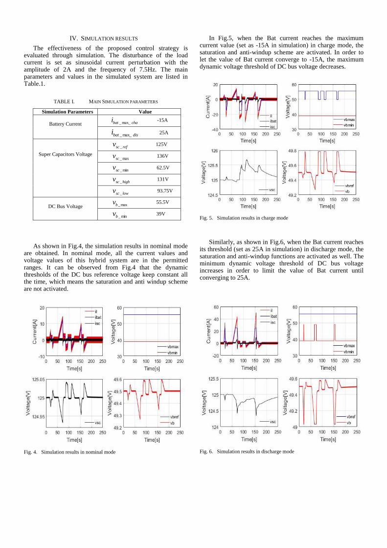
IV. SIMULATION RESULTS
The effectiveness of the proposed control strategy is evaluated through simulation. The disturbance of the load current is set as sinusoidal current perturbation with the amplitude of 2A and the frequency of 7.5Hz. The main parameters and values in the simulated system are listed in Table.1.
TABLE I. MAIN SIMULATION PARAMETERS
Simulation Parameters Value
Battery Current
chabati max__ -15A
disbati max__
25A
Super Capacitors Voltage
refscv _
125V
max_scv 136V
min_scv 62.5V
highscv _
131V
lowscv _
93.75V
DC Bus Voltage max_bv 55.5V
min_bv 39V
As shown in Fig.4, the simulation results in nominal mode are obtained. In nominal mode, all the current values and voltage values of this hybrid system are in the permitted ranges. It can be observed from Fig.4 that the dynamic thresholds of the DC bus reference voltage keep constant all the time, which means the saturation and anti windup scheme are not activated.
Fig. 4. Simulation results in nominal mode
In Fig.5, when the Bat current reaches the maximum current value (set as -15A in simulation) in charge mode, the saturation and anti-windup scheme are activated. In order to let the value of Bat current converge to -15A, the maximum dynamic voltage threshold of DC bus voltage decreases.
Fig. 5. Simulation results in charge mode
Similarly, as shown in Fig.6, when the Bat current reaches its threshold (set as 25A in simulation) in discharge mode, the saturation and anti-windup functions are activated as well. The minimum dynamic voltage threshold of DC bus voltage increases in order to limit the value of Bat current until converging to 25A.
Fig. 6. Simulation results in discharge mode
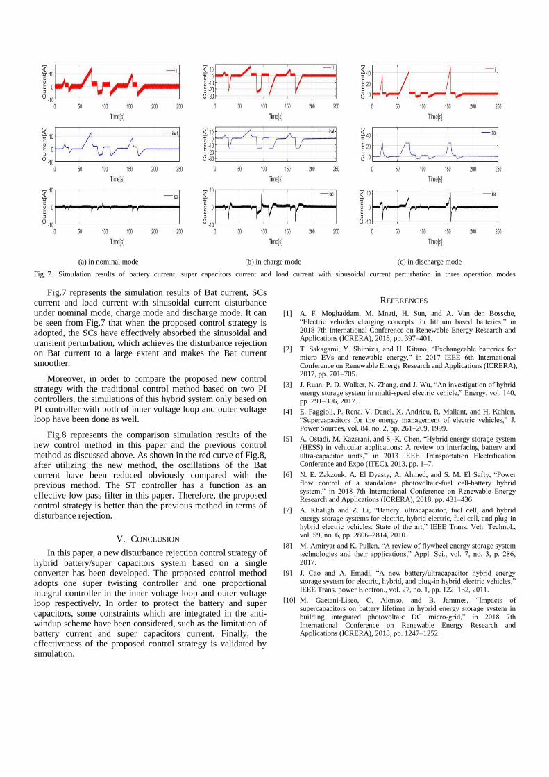
(a) in nominal mode (b) in charge mode (c) in discharge mode
Fig. 7. Simulation results of battery current, super capacitors current and load current with sinusoidal current perturbation in three operation modes
Fig.7 represents the simulation results of Bat current, SCs current and load current with sinusoidal current disturbance under nominal mode, charge mode and discharge mode. It can be seen from Fig.7 that when the proposed control strategy is adopted, the SCs have effectively absorbed the sinusoidal and transient perturbation, which achieves the disturbance rejection on Bat current to a large extent and makes the Bat current smoother.
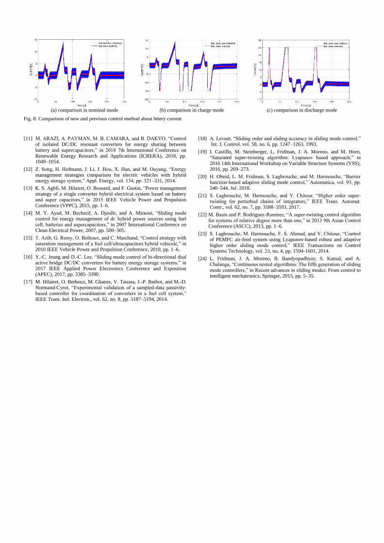
Moreover, in order to compare the proposed new control strategy with the traditional control method based on two PI controllers, the simulations of this hybrid system only based on PI controller with both of inner voltage loop and outer voltage loop have been done as well.
Fig.8 represents the comparison simulation results of the new control method in this paper and the previous control method as discussed above. As shown in the red curve of Fig.8, after utilizing the new method, the oscillations of the Bat current have been reduced obviously compared with the previous method. The ST controller has a function as an effective low pass filter in this paper. Therefore, the proposed control strategy is better than the previous method in terms of disturbance rejection.
V. CONCLUSION
In this paper, a new disturbance rejection control strategy of hybrid battery/super capacitors system based on a single converter has been developed. The proposed control method adopts one super twisting controller and one proportional integral controller in the inner voltage loop and outer voltage loop respectively. In order to protect the battery and super capacitors, some constraints which are integrated in the anti-windup scheme have been considered, such as the limitation of battery current and super capacitors current. Finally, the effectiveness of the proposed control strategy is validated by simulation.
REFERENCES
[1] A. F. Moghaddam, M. Mnati, H. Sun, and A. Van den Bossche, “Electric vehicles charging concepts for lithium based batteries,” in 2018 7th International Conference on Renewable Energy Research and Applications (ICRERA), 2018, pp. 397–401.
[2] T. Sakagami, Y. Shimizu, and H. Kitano, “Exchangeable batteries for micro EVs and renewable energy,” in 2017 IEEE 6th International Conference on Renewable Energy Research and Applications (ICRERA), 2017, pp. 701–705.
[3] J. Ruan, P. D. Walker, N. Zhang, and J. Wu, “An investigation of hybrid energy storage system in multi-speed electric vehicle,” Energy, vol. 140, pp. 291–306, 2017.
[4] E. Faggioli, P. Rena, V. Danel, X. Andrieu, R. Mallant, and H. Kahlen, “Supercapacitors for the energy management of electric vehicles,” J. Power Sources, vol. 84, no. 2, pp. 261–269, 1999.
[5] A. Ostadi, M. Kazerani, and S.-K. Chen, “Hybrid energy storage system (HESS) in vehicular applications: A review on interfacing battery and ultra-capacitor units,” in 2013 IEEE Transportation Electrification Conference and Expo (ITEC), 2013, pp. 1–7.
[6] N. E. Zakzouk, A. El Dyasty, A. Ahmed, and S. M. El Safty, “Power flow control of a standalone photovoltaic-fuel cell-battery hybrid system,” in 2018 7th International Conference on Renewable Energy Research and Applications (ICRERA), 2018, pp. 431–436.
[7] A. Khaligh and Z. Li, “Battery, ultracapacitor, fuel cell, and hybrid energy storage systems for electric, hybrid electric, fuel cell, and plug-in hybrid electric vehicles: State of the art,” IEEE Trans. Veh. Technol., vol. 59, no. 6, pp. 2806–2814, 2010.
[8] M. Amiryar and K. Pullen, “A review of flywheel energy storage system technologies and their applications,” Appl. Sci., vol. 7, no. 3, p. 286, 2017.
[9] J. Cao and A. Emadi, “A new battery/ultracapacitor hybrid energy storage system for electric, hybrid, and plug-in hybrid electric vehicles,” IEEE Trans. power Electron., vol. 27, no. 1, pp. 122–132, 2011.
[10] M. Gaetani-Liseo, C. Alonso, and B. Jammes, “Impacts of supercapacitors on battery lifetime in hybrid energy storage system in building integrated photovoltaic DC micro-grid,” in 2018 7th International Conference on Renewable Energy Research and Applications (ICRERA), 2018, pp. 1247–1252.
(a) comparison in nominal mode (b) comparison in charge mode (c) comparison in discharge mode
Fig. 8. Comparison of new and previous control method about bttery current
[11] M. ARAZI, A. PAYMAN, M. B. CAMARA, and B. DAKYO, “Control of isolated DC/DC resonant converters for energy sharing between battery and supercapacitors,” in 2018 7th International Conference on Renewable Energy Research and Applications (ICRERA), 2018, pp. 1049–1054.
[12] Z. Song, H. Hofmann, J. Li, J. Hou, X. Han, and M. Ouyang, “Energy management strategies comparison for electric vehicles with hybrid energy storage system,” Appl. Energy, vol. 134, pp. 321–331, 2014.
[13] K. S. Agbli, M. Hilairet, O. Bossard, and F. Gustin, “Power management strategy of a single converter hybrid electrical system based on battery and super capacitors,” in 2015 IEEE Vehicle Power and Propulsion Conference (VPPC), 2015, pp. 1–6.
[14] M. Y. Ayad, M. Becherif, A. Djerdir, and A. Miraoui, “Sliding mode control for energy management of dc hybrid power sources using fuel cell, batteries and supercapacitors,” in 2007 International Conference on Clean Electrical Power, 2007, pp. 500–505.
[15] T. Azib, G. Remy, O. Bethoux, and C. Marchand, “Control strategy with saturation management of a fuel cell/ultracapacitors hybrid vehicule,” in 2010 IEEE Vehicle Power and Propulsion Conference, 2010, pp. 1–6.
[16] Y.-C. Jeung and D.-C. Lee, “Sliding mode control of bi-directional dual active bridge DC/DC converters for battery energy storage systems,” in 2017 IEEE Applied Power Electronics Conference and Exposition (APEC), 2017, pp. 3385–3390.
[17] M. Hilairet, O. Bethoux, M. Ghanes, V. Tanasa, J.-P. Barbot, and M.-D. Normand-Cyrot, “Experimental validation of a sampled-data passivity-based controller for coordination of converters in a fuel cell system,” IEEE Trans. Ind. Electron., vol. 62, no. 8, pp. 5187–5194, 2014.
[18] A. Levant, “Sliding order and sliding accuracy in sliding mode control,” Int. J. Control, vol. 58, no. 6, pp. 1247–1263, 1993.
[19] I. Castillo, M. Steinberger, L. Fridman, J. A. Moreno, and M. Horn, “Saturated super-twisting algorithm: Lyapunov based approach,” in 2016 14th International Workshop on Variable Structure Systems (VSS), 2016, pp. 269–273.
[20] H. Obeid, L. M. Fridman, S. Laghrouche, and M. Harmouche, “Barrier function-based adaptive sliding mode control,” Automatica, vol. 93, pp. 540–544, Jul. 2018.
[21] S. Laghrouche, M. Harmouche, and Y. Chitour, “Higher order super-twisting for perturbed chains of integrators,” IEEE Trans. Automat. Contr., vol. 62, no. 7, pp. 3588–3593, 2017.
[22] M. Basin and P. Rodriguez-Ramirez, “A super-twisting control algorithm for systems of relative degree more than one,” in 2013 9th Asian Control Conference (ASCC), 2013, pp. 1–6.
[23] S. Laghrouche, M. Harmouche, F. S. Ahmed, and Y. Chitour, “Control of PEMFC air-feed system using Lyapunov-based robust and adaptive higher order sliding mode control,” IEEE Transactions on Control Systems Technology, vol. 23, no. 4, pp. 1594-1601, 2014.
[24] L. Fridman, J. A. Moreno, B. Bandyopadhyay, S. Kamal, and A. Chalanga, “Continuous nested algorithms: The fifth generation of sliding mode controllers,” in Recent advances in sliding modes: From control to intelligent mechatronics, Springer, 2015, pp. 5–35.