105
DIVAR 2000 / DIVAR 3000 / DIVAR 5000 Network/Hybrid Video Recorder en Operation Manual
DIVAR 2000 / DIVAR 3000 / DIVAR 5000Network/Hybrid Video Recorder
en Operation Manual

DIVAR 2000 / DIVAR 3000 / DIVAR 5000 Table of contents | en 3
Bosch Security Systems Operation Manual 2018.10 | V2.0 | AM18-Q0717
Table of contents1 Safety 71.1 Important safety instructions 71.2 FCC and UL 92 Short information 103 System overview 114 Planning information 124.1 Unpacking 124.2 Package contents 125 Installation 135.1 Unpacking 135.1.1 Package contents 135.2 Make connections 145.2.1 Back panel connectors DIVAR network 2000/3000 (no PoE) 155.2.2 Back panel connectors DIVAR network 2000 (8 PoE) 165.2.3 Back panel connectors DIVAR network 2000/3000 (16 PoE) 175.2.4 Back panel connectors DIVAR network 5000 (no PoE) 185.2.5 Back panel connectors DIVAR network 5000 (16 PoE) 195.2.6 Back panel connectors DIVAR hybrid 3000 205.2.7 Back panel connectors DIVAR hybrid 5000 215.2.8 Browser setup 215.3 Powering up 225.4 Startup wizard 225.5 Login 235.6 Logout/Shutdown 236 First time operation 246.1 Live viewing mode 246.2 Quick menu 256.3 Main menu 257 Hardware setup 277.1 Keyboard connection (only DIVAR 5000 models) 277.1.1 Connect using RJ11 adapter 287.1.2 Connect wires directly 297.2 RS485 port connection (only hybrid models) 297.3 RS232 port connections 307.4 Alarm I/O connections 318 Settings 328.1 System 328.1.1 General 328.1.2 Playback 338.1.3 Display 338.1.4 Serial port 358.1.5 Text/Pos (only on hybrid recorders) 368.1.6 Account 368.1.7 Service 378.2 Network 398.2.1 Connection 398.2.2 DDNS 418.2.3 Mobile 42
4 en | Table of contents DIVAR 2000 / DIVAR 3000 / DIVAR 5000
2018.10 | V2.0 | AM18-Q0717 Operation Manual Bosch Security Systems
8.2.4 Bandwidth 428.2.5 UPnP 438.2.6 PPPoE 438.2.7 SNMP 438.2.8 Email 448.2.9 Storage 448.2.10 IP filter 458.2.11 Certificates 458.3 Camera 468.3.1 Detection 468.3.2 Configuration 468.3.3 Recording 478.3.4 Installer 508.3.5 Maintenance 518.3.6 Channel type 528.4 Alarm 538.4.1 Motion detect 538.4.2 Video loss 548.4.3 Input alarm 548.4.4 System alarm 548.4.5 Alarm Out 558.5 Schedule 568.5.1 Weekdays and Holidays 568.6 Storage 578.6.1 HDD manage 578.6.2 Recording 579 Operation 599.1 User controls and menus 599.1.1 Mouse Controls 599.1.2 Front panel controls 609.1.3 Remote control 629.1.4 Quick menu 659.1.5 Main menu 659.2 Live screen 659.2.1 Live mode 669.2.2 Pan/Tilt/Zoom 679.2.3 Sequence 679.2.4 Monitor A 689.2.5 Monitor B (only for DIVAR 5000 models) 689.3 Playback 699.3.1 Export 759.3.2 Export snapshot 759.4 Info 759.4.1 System Alarm 759.4.2 System Health 759.4.3 System Version 769.4.4 Network Online users 769.4.5 PoE usage 769.4.6 Network Load 76
DIVAR 2000 / DIVAR 3000 / DIVAR 5000 Table of contents | en 5
Bosch Security Systems Operation Manual 2018.10 | V2.0 | AM18-Q0717
9.4.7 Network Test 769.4.8 HDD General 779.4.9 HDD Health 779.4.10 Log 789.5 Export 789.6 Event search 7910 Archive Player operation 8010.1 Getting started 8010.1.1 System requirements 8010.1.2 Installation 8010.1.3 Starting the Player 8010.2 Authentication (checking watermark) 8310.3 Export file 8310.4 Configuration 8411 Web Client Software 8511.1 Getting started 8511.2 How to log on 8611.3 Web client live window 8611.3.1 Live 8611.3.2 Playback mode 8711.3.3 Event search 8711.3.4 Export 8711.3.5 Setting 8811.3.6 Info 8811.3.7 Logout 8812 DIVAR Mobile Viewer 8912.1 Getting started 8912.2 Live Preview 8912.3 Playback 9012.4 Device Manager 9012.5 Local Files 9112.6 Favorites 9112.7 Alarms and Push notifications 9112.8 More 9113 Troubleshooting 9314 Maintenance 9714.1 Insert DIVAR 5000 in rack 9714.2 Replace internal battery 9714.3 Install HDD 9714.4 Install DVD 9715 Decommissioning 9815.1 Transfer 9815.2 Disposal 9816 Technical data 9917 Appendices 10117.1 Software licenses 10117.1.1 Bosch software 10117.1.2 Other licenses — copyright notices 10117.1.3 Warranties and disclaimer of warranties 102
6 en | Table of contents DIVAR 2000 / DIVAR 3000 / DIVAR 5000
2018.10 | V2.0 | AM18-Q0717 Operation Manual Bosch Security Systems
17.2 DVD Compatibility 10217.3 HDD Compatibility 103
DIVAR 2000 / DIVAR 3000 / DIVAR 5000 Safety | en 7
Bosch Security Systems Operation Manual 2018.10 | V2.0 | AM18-Q0717
1 Safety
!
Warning!Indicates a hazardous situation which, if not avoided, could result in death or serious injury.
!
Caution!Indicates a hazardous situation which, if not avoided, could result in minor or moderateinjury.
Notice!Indicates a situation which, if not avoided, could result in damage to the equipment orenvironment, or data loss.
1.1 Important safety instructions
Video loss - Video loss is inherent to digital video recording; therefore, Bosch SecuritySystems cannot be held liable for any damage that results from missing video information.To minimize the risk of losing information, we recommend multiple, redundant recordingsystems, and a procedure to back up all analog and digital information.
Accessories - Do not place this unit on an unstable stand, tripod, bracket,or mount. The unit may fall, causing serious injury and/or serious damage tothe unit. Use only with the cart, stand, tripod, bracket, or table specified bythe manufacturer. When a cart is used, use caution and care when movingthe cart/apparatus combination to avoid injury from tip-over. Quick stops,excessive force, or uneven surfaces may cause the cart/unit combination tooverturn. Mount the unit per the manufacturer's instructions.
Read, follow, and retain for future reference all of the following safety instructions. Heed allwarnings on the unit and in the operating instructions before operating the unit.1. Cleaning - Unplug the unit from the outlet before cleaning. Follow any instructions
provided with the unit. Generally, using a dry cloth for cleaning is sufficient but a moist,fluff-free cloth or leather shammy may also be used. Do not use liquid cleaners or aerosolcleaners.
2. Heat Sources - Do not install the unit near any heat sources such as radiators, heaters,stoves, or other equipment (including amplifiers) that produce heat.
3. Ventilation - Any openings in the unit enclosure are provided for ventilation to preventoverheating and ensure reliable operation. Do not block or cover these openings. Do notplace the unit in an enclosure unless proper ventilation is provided, or the manufacturer'sinstructions have been adhered to.
4. Water - Do not use this unit near water, for example near a bathtub, washbowl, sink,laundry basket, in a damp or wet basement, near a swimming pool, in an outdoorinstallation, or in any area classified as a wet location. To reduce the risk of fire orelectrical shock, do not expose this unit to rain or moisture.
8 en | Safety DIVAR 2000 / DIVAR 3000 / DIVAR 5000
2018.10 | V2.0 | AM18-Q0717 Operation Manual Bosch Security Systems
5. Object and liquid entry - Never push objects of any kind into this unit through openingsas they may touch dangerous voltage points or short-out parts that could result in a fireor electrical shock. Never spill liquid of any kind on the unit. Do not place objects filledwith liquids, such as vases or cups, on the unit.
6. Lightning - For added protection during a lightning storm, or when leaving this unitunattended and unused for long periods, unplug the unit from the wall outlet anddisconnect the cable system. This will prevent damage to the unit from lightning andpower line surges.
7. Controls adjustment - Adjust only those controls specified in the operating instructions.Improper adjustment of other controls may cause damage to the unit. Use of controls oradjustments, or performance of procedures other than those specified, may result inhazardous radiation exposure.
8. Overloading - Do not overload outlets and extension cords. This can cause fire orelectrical shock.
9. Power supply cord and plug protection - Power supply cords should be routed so thatthey are not likely to be walked on or pinched by items placed upon or against them,playing particular attention to cords and plugs, convenience receptacles, and the pointwhere they exit from the appliance.
10. Power disconnect - Units have power supplied to the unit whenever the power cord isinserted into the power source. The power cord plug is the main power disconnect devicefor switching off the voltage for the unit.
11. Power sources - Operate the unit only from the type of power source indicated on thelabel. Before proceeding, be sure to disconnect the power from the cable to be installedinto the unit.
12. Servicing - Do not attempt to service this unit yourself. Opening or removing covers mayexpose you to dangerous voltage or other hazards. Refer all servicing to qualified servicepersonnel.
13. Damage requiring service - Unplug the power unit from the main AC power source andrefer servicing to qualified service personnel when any damage to the equipment hasoccurred, such as:– the power supply cord or plug is damaged;– exposure to moisture, water, and/or inclement weather (rain, snow, etc.);– liquid has been spilled in or on the equipment;– an object has fallen into the unit;– unit has been dropped or the unit cabinet is damaged;– unit exhibits a distinct change in performance;– unit does not operate normally when the user correctly follows the operating
instructions.14. Replacement parts - Be sure the service technician uses replacement parts specified by
the manufacturer, or that have the same characteristics as the original parts.Unauthorized substitutions could void the warranty and cause fire, electrical shock, orother hazards.
15. Safety check - Safety checks should be performed upon completion of service or repairsto the unit to ensure proper operating condition.
16. Installation - Install in accordance with the manufacturer's instructions and in accordancewith applicable local codes.
DIVAR 2000 / DIVAR 3000 / DIVAR 5000 Safety | en 9
Bosch Security Systems Operation Manual 2018.10 | V2.0 | AM18-Q0717
17. Attachments, changes or modifications - Only use attachments/accessories specified bythe manufacturer. Any change or modification of the equipment, not expressly approvedby Bosch, could void the warranty or, in the case of an authorization agreement, authorityto operate the equipment.
1.2 FCC and ULFCC & ICES InformationThis equipment has been tested and found to comply with the limits for a Class B digitaldevice, pursuant to part 15 of the FCC Rules. These limits are designed to provide reasonableprotection against harmful interference in a residential installation. This equipmentgenerates, uses, and can radiate radio frequency energy and, if not installed and used inaccordance with the instructions, may cause harmful interference to radio communications.However, there is no guarantee that interference will not occur in a particular installation. Ifthis equipment does cause harmful interference to radio or television reception, which can bedetermined by turning the equipment off and on, the user is encouraged to try to correct theinterference by one or more of the following measures:– reorient or relocate the receiving antenna;– increase the separation between the equipment and receiver;– connect the equipment into an outlet on a circuit different from that to which the receiver
is connected;– consult the dealer or an experienced radio/TV technician for help.Intentional or unintentional modifications, not expressly approved by the party responsible forcompliance, shall not be made. Any such modifications could void the user's authority tooperate the equipment. If necessary, the user should consult the dealer or an experiencedradio/television technician for corrective action.The user may find the following booklet, prepared by the Federal CommunicationsCommission, helpful: How to Identify and Resolve Radio-TV Interference Problems. Thisbooklet is available from the U.S. Government Printing Office, Washington, DC 20402, StockNo. 004-000-00345-4.
UL DisclaimerUnderwriter Laboratories Inc. ("UL") has not tested the performance or reliability of thesecurity or signaling aspects of this product. UL has only tested fire, shock and/or casualtyhazards as outlined in Standard(s) for Safety for Information Technology Equipment, UL60950-1 . UL Certification does not cover the performance or reliability of the security orsignaling aspects of this product.UL MAKES NO REPRESENTATIONS, WARRANTIES, OR CERTIFICATIONS WHATSOEVERREGARDING THE PERFORMANCE OR RELIABILITY OF ANY SECURITY OR SIGNALING-RELATEDFUNCTIONS OF THIS PRODUCT.
10 en | Short information DIVAR 2000 / DIVAR 3000 / DIVAR 5000
2018.10 | V2.0 | AM18-Q0717 Operation Manual Bosch Security Systems
2 Short informationThis manual has been compiled with great care and the information it contains has beenthoroughly verified. The text was correct at the time of printing, however, the content canchange without notice. Bosch Security Systems accepts no liability for damage resultingdirectly or indirectly from faults, incompleteness or discrepancies between this manual andthe product described.
TrademarksAll hardware and software product names used in this document are likely to be registeredtrademarks and must be treated accordingly.
More informationFor more information please contact the nearest Bosch Security Systems location or visitwww.boschsecurity.com
http://www.boschsecurity.com/catalog_overview.htm
DIVAR 2000 / DIVAR 3000 / DIVAR 5000 System overview | en 11
Bosch Security Systems Operation Manual 2018.10 | V2.0 | AM18-Q0717
3 System overviewThe recorder can be connected to cameras that use the latest H.264/H.265 high-resolutionvideo technology and state-of-the-art compression techniques. These advanced technologies,coupled with efficient network data transmission, deliver the high security and reliabilityrequired for modern surveillance systems.Simultaneous remote or local monitoring, recording, archiving and playback are guided bysimple menu selections and operator commands. The recorders can be installed with optionalHDDs for video storage; plus a DVD burner for video export.
Notice!Bosch strongly recommends upgrading to the latest firmware for the best possiblefunctionality, compatibility, performance and security.Check http://downloadstore.boschsecurity.com/ regularly to see if there is a new firmwareversion available.
Notice!Bosch strongly recommends to use https (instead of http) for secure communication.
12 en | Planning information DIVAR 2000 / DIVAR 3000 / DIVAR 5000
2018.10 | V2.0 | AM18-Q0717 Operation Manual Bosch Security Systems
4 Planning information4.1 Unpacking
This equipment should be unpacked and handled with care. If an item appears to have beendamaged in shipment, notify the shipper immediately.Verify that all parts are included. If any items are missing, notify your Bosch Security SystemsSales or Customer Service Representative.The original packaging is the safest container in which to transport the unit and can be used ifreturning the unit for service.
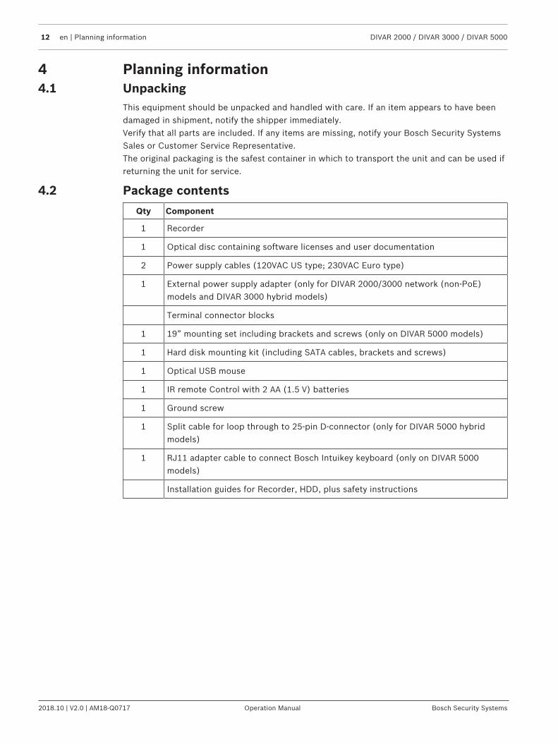
4.2 Package contents
Qty Component
1 Recorder
1 Optical disc containing software licenses and user documentation
2 Power supply cables (120VAC US type; 230VAC Euro type)
1 External power supply adapter (only for DIVAR 2000/3000 network (non-PoE)models and DIVAR 3000 hybrid models)
Terminal connector blocks
1 19” mounting set including brackets and screws (only on DIVAR 5000 models)
1 Hard disk mounting kit (including SATA cables, brackets and screws)
1 Optical USB mouse
1 IR remote Control with 2 AA (1.5 V) batteries
1 Ground screw
1 Split cable for loop through to 25-pin D-connector (only for DIVAR 5000 hybridmodels)
1 RJ11 adapter cable to connect Bosch Intuikey keyboard (only on DIVAR 5000models)
Installation guides for Recorder, HDD, plus safety instructions
DIVAR 2000 / DIVAR 3000 / DIVAR 5000 Installation | en 13
Bosch Security Systems Operation Manual 2018.10 | V2.0 | AM18-Q0717
5 InstallationNotice!Use proper surge suppression on cables that are routed outdoors, or close to large inductiveloads or electrical mains supply cables.
!
Caution!Installation should only be performed by qualified service personnel in accordance with theNational Electrical Code (NEC 800 CEC Section 60) or applicable local codes.
To get the unit operational, perform the following quick install steps:1. Carefully unpack the recorder from its shipping packaging – see Unpacking.2. Make all required hardware connections – see ‘Make Connections’.3. Power up the system – see Powering Up.4. Log in – see Login.5. Correctly configure your system software with the Startup wizard (this appears the first
time the unit is started) – see Startup Wizard.After completing this initial setup, the system is ready to run and will show a live view of thecamera image(s). If required, you can alter the settings later using the menus and/or factorydefaults, or you can run the Startup wizard again.
5.1 UnpackingThis equipment should be unpacked and handled with care. If an item appears to have beendamaged in shipment, notify the shipper immediately.Verify that all parts are included. If any items are missing, notify your Bosch Security SystemsSales or Customer Service Representative.The original packaging is the safest container in which to transport the unit and can be used ifreturning the unit for service.
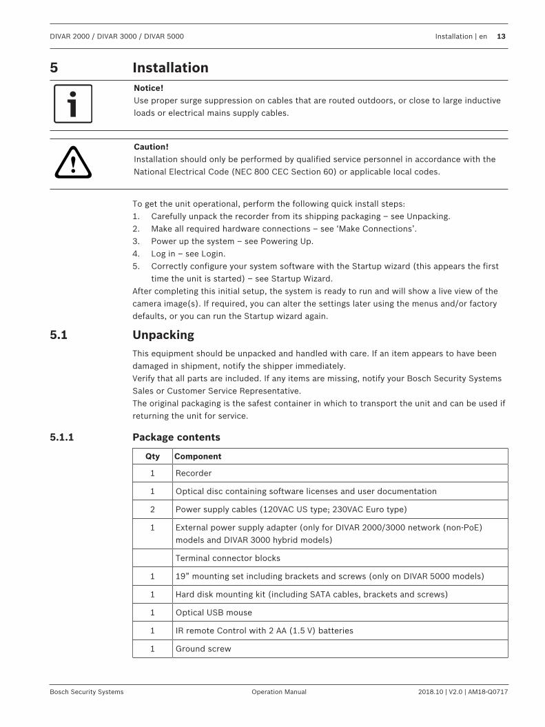
5.1.1 Package contents
Qty Component
1 Recorder
1 Optical disc containing software licenses and user documentation
2 Power supply cables (120VAC US type; 230VAC Euro type)
1 External power supply adapter (only for DIVAR 2000/3000 network (non-PoE)models and DIVAR 3000 hybrid models)
Terminal connector blocks
1 19” mounting set including brackets and screws (only on DIVAR 5000 models)
1 Hard disk mounting kit (including SATA cables, brackets and screws)
1 Optical USB mouse
1 IR remote Control with 2 AA (1.5 V) batteries
1 Ground screw
14 en | Installation DIVAR 2000 / DIVAR 3000 / DIVAR 5000
2018.10 | V2.0 | AM18-Q0717 Operation Manual Bosch Security Systems
Qty Component
1 Split cable for loop through to 25-pin D-connector (only for DIVAR 5000 hybridmodels)
1 RJ11 adapter cable to connect Bosch Intuikey keyboard (only on DIVAR 5000models)
Installation guides for Recorder, HDD, plus safety instructions
5.2 Make connections
Notice!Use only PoE approved devices.
1. Connect the cameras to the or connectors.– If using PoE connector, power is supplied to the camera via the Ethernet cable
compliant with the Power-over-Ethernet standard.– Use an external switch to connect more cameras to a single RJ45 port.
2. Connect monitor A to the output, or the output.3. Connect the USB mouse to a USB port (back or front panel).
Optional connections (depending on model)1. On DIVAR 5000 models, connect a second dual monitor to the HDMI MON.B (hybrid
models) or HDMI MON.A2 (network models) connector.2. Connect up to 4 audio signals to the RCA (CINCH) inputs.3. Connect 1 microphone to the RCA (CINCH) input.4. Connect 1 RCA (CINCH) output from to the monitor or an audio amplifier.5. Connect up to 16 alarm inputs to the connector (via the supplied terminal
blocks) – see description in Hardware setup.6. Connect up to 6 alarm outputs to the connector (via the supplied terminal
blocks) – see description in Hardware setup.7. Connect a pan/tilt/zoom control unit to the (only for hybrid models) – see
description in Hardware setup.
8. Connect to your network via the RJ45 ETHERNET connector (use Shielded TwistedPair Category 5e cable).
9. Connect extra video out cables to the ports if loop through is required to otherdevices (only for DIVAR 5000 hybrid).
10. Connect a Bosch Intuikey keyboard cable to the connector using the suppliedadaptor (only for DIVAR 5000) – see description in Hardware setup.
11. Connect an eSATA storage device to the connector (only for DIVAR 5000).12. Connect the DIVAR to an approved ground point. Use the ground screw (supplied in the
accessory bag) to attach a ground cable to the DIVARback panel ground point .
DIVAR 2000 / DIVAR 3000 / DIVAR 5000 Installation | en 15
Bosch Security Systems Operation Manual 2018.10 | V2.0 | AM18-Q0717
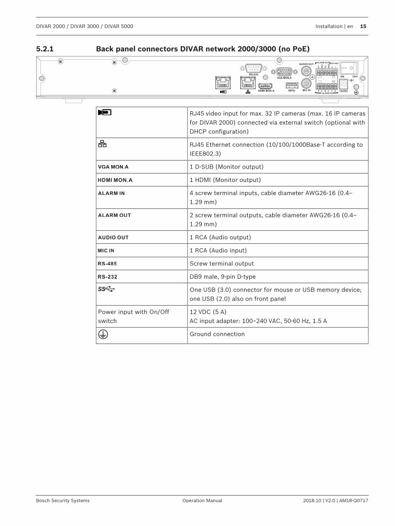
5.2.1 Back panel connectors DIVAR network 2000/3000 (no PoE)
RJ45 video input for max. 32 IP cameras (max. 16 IP camerasfor DIVAR 2000) connected via external switch (optional withDHCP configuration)
RJ45 Ethernet connection (10/100/1000Base-T according toIEEE802.3)
1 D-SUB (Monitor output)
1 HDMI (Monitor output)
4 screw terminal inputs, cable diameter AWG26‑16 (0.4–1.29 mm)
2 screw terminal outputs, cable diameter AWG26‑16 (0.4–1.29 mm)
1 RCA (Audio output)
1 RCA (Audio input)
Screw terminal output
DB9 male, 9-pin D-type
One USB (3.0) connector for mouse or USB memory device;one USB (2.0) also on front panel
Power input with On/Offswitch
12 VDC (5 A)AC input adapter: 100~240 VAC, 50-60 Hz, 1.5 A
Ground connection
16 en | Installation DIVAR 2000 / DIVAR 3000 / DIVAR 5000
2018.10 | V2.0 | AM18-Q0717 Operation Manual Bosch Security Systems
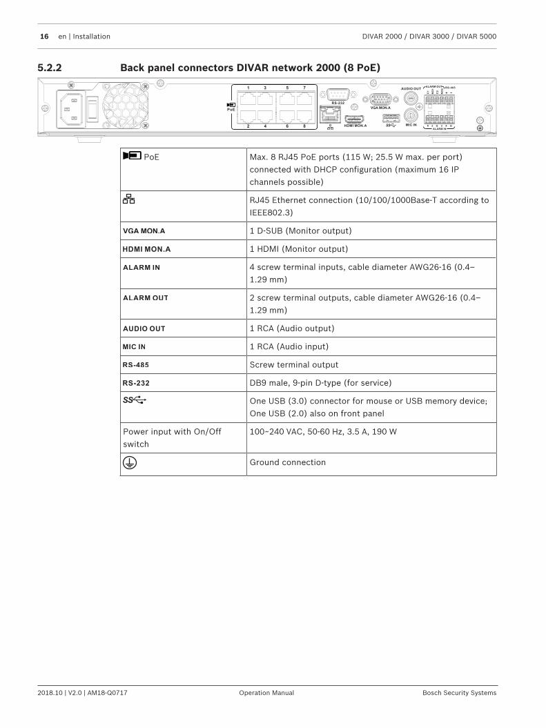
5.2.2 Back panel connectors DIVAR network 2000 (8 PoE)
PoE Max. 8 RJ45 PoE ports (115 W; 25.5 W max. per port)connected with DHCP configuration (maximum 16 IPchannels possible)
RJ45 Ethernet connection (10/100/1000Base-T according toIEEE802.3)
1 D-SUB (Monitor output)
1 HDMI (Monitor output)
4 screw terminal inputs, cable diameter AWG26‑16 (0.4–1.29 mm)
2 screw terminal outputs, cable diameter AWG26‑16 (0.4–1.29 mm)
1 RCA (Audio output)
1 RCA (Audio input)
Screw terminal output
DB9 male, 9-pin D-type (for service)
One USB (3.0) connector for mouse or USB memory device;One USB (2.0) also on front panel
Power input with On/Offswitch
100~240 VAC, 50-60 Hz, 3.5 A, 190 W
Ground connection
DIVAR 2000 / DIVAR 3000 / DIVAR 5000 Installation | en 17
Bosch Security Systems Operation Manual 2018.10 | V2.0 | AM18-Q0717
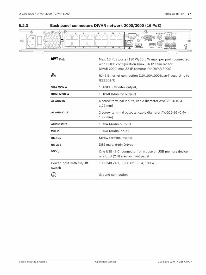
5.2.3 Back panel connectors DIVAR network 2000/3000 (16 PoE)
PoE Max. 16 PoE ports (130 W; 25.5 W max. per port) connectedwith DHCP configuration (max. 16 IP cameras forDIVAR 2000; max 32 IP cameras for DIVAR 3000)
RJ45 Ethernet connection (10/100/1000Base-T according toIEEE802.3)
1 D-SUB (Monitor output)
1 HDMI (Monitor output)
4 screw terminal inputs, cable diameter AWG26‑16 (0.4–1.29 mm)
2 screw terminal outputs, cable diameter AWG26‑16 (0.4–1.29 mm)
1 RCA (Audio output)
1 RCA (Audio input)
Screw terminal output
DB9 male, 9-pin D-type
One USB (3.0) connector for mouse or USB memory device;one USB (2.0) also on front panel
Power input with On/Offswitch
100~240 VAC, 50-60 Hz, 3.5 A, 190 W
Ground connection
18 en | Installation DIVAR 2000 / DIVAR 3000 / DIVAR 5000
2018.10 | V2.0 | AM18-Q0717 Operation Manual Bosch Security Systems
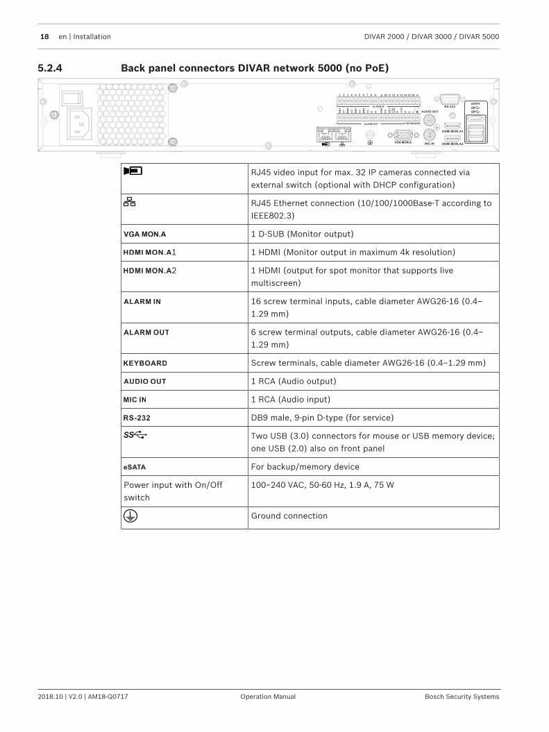
5.2.4 Back panel connectors DIVAR network 5000 (no PoE)
RJ45 video input for max. 32 IP cameras connected viaexternal switch (optional with DHCP configuration)
RJ45 Ethernet connection (10/100/1000Base-T according toIEEE802.3)
1 D-SUB (Monitor output)
1 1 HDMI (Monitor output in maximum 4k resolution)
2 1 HDMI (output for spot monitor that supports livemultiscreen)
16 screw terminal inputs, cable diameter AWG26‑16 (0.4–1.29 mm)
6 screw terminal outputs, cable diameter AWG26‑16 (0.4–1.29 mm)
Screw terminals, cable diameter AWG26‑16 (0.4–1.29 mm)
1 RCA (Audio output)
1 RCA (Audio input)
DB9 male, 9-pin D-type (for service)
Two USB (3.0) connectors for mouse or USB memory device;one USB (2.0) also on front panel
For backup/memory device
Power input with On/Offswitch
100~240 VAC, 50-60 Hz, 1.9 A, 75 W
Ground connection
DIVAR 2000 / DIVAR 3000 / DIVAR 5000 Installation | en 19
Bosch Security Systems Operation Manual 2018.10 | V2.0 | AM18-Q0717
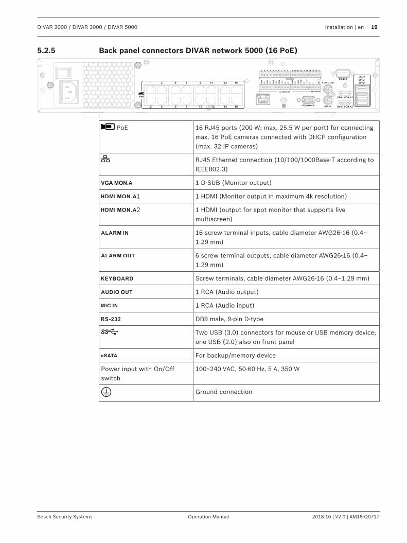
5.2.5 Back panel connectors DIVAR network 5000 (16 PoE)
PoE 16 RJ45 ports (200 W; max. 25.5 W per port) for connectingmax. 16 PoE cameras connected with DHCP configuration(max. 32 IP cameras)
RJ45 Ethernet connection (10/100/1000Base-T according toIEEE802.3)
1 D-SUB (Monitor output)
1 1 HDMI (Monitor output in maximum 4k resolution)
2 1 HDMI (output for spot monitor that supports livemultiscreen)
16 screw terminal inputs, cable diameter AWG26‑16 (0.4–1.29 mm)
6 screw terminal outputs, cable diameter AWG26‑16 (0.4–1.29 mm)
Screw terminals, cable diameter AWG26‑16 (0.4–1.29 mm)
1 RCA (Audio output)
1 RCA (Audio input)
DB9 male, 9-pin D-type
Two USB (3.0) connectors for mouse or USB memory device;one USB (2.0) also on front panel
For backup/memory device
Power input with On/Offswitch
100~240 VAC, 50-60 Hz, 5 A, 350 W
Ground connection
20 en | Installation DIVAR 2000 / DIVAR 3000 / DIVAR 5000
2018.10 | V2.0 | AM18-Q0717 Operation Manual Bosch Security Systems
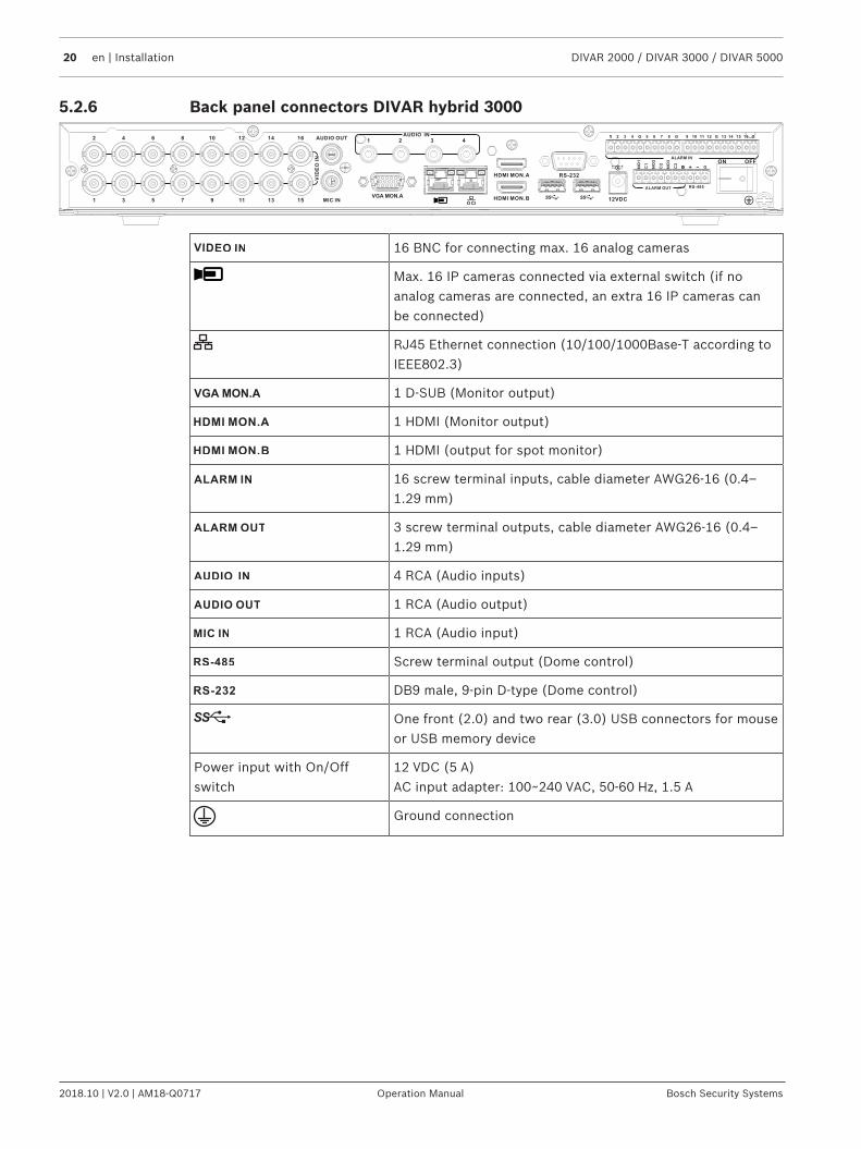
5.2.6 Back panel connectors DIVAR hybrid 3000
16 BNC for connecting max. 16 analog cameras
Max. 16 IP cameras connected via external switch (if noanalog cameras are connected, an extra 16 IP cameras canbe connected)
RJ45 Ethernet connection (10/100/1000Base-T according toIEEE802.3)
1 D-SUB (Monitor output)
1 HDMI (Monitor output)
1 HDMI (output for spot monitor)
16 screw terminal inputs, cable diameter AWG26‑16 (0.4–1.29 mm)
3 screw terminal outputs, cable diameter AWG26‑16 (0.4–1.29 mm)
4 RCA (Audio inputs)
1 RCA (Audio output)
1 RCA (Audio input)
Screw terminal output (Dome control)
DB9 male, 9-pin D-type (Dome control)
One front (2.0) and two rear (3.0) USB connectors for mouseor USB memory device
Power input with On/Offswitch
12 VDC (5 A)AC input adapter: 100~240 VAC, 50-60 Hz, 1.5 A
Ground connection
DIVAR 2000 / DIVAR 3000 / DIVAR 5000 Installation | en 21
Bosch Security Systems Operation Manual 2018.10 | V2.0 | AM18-Q0717
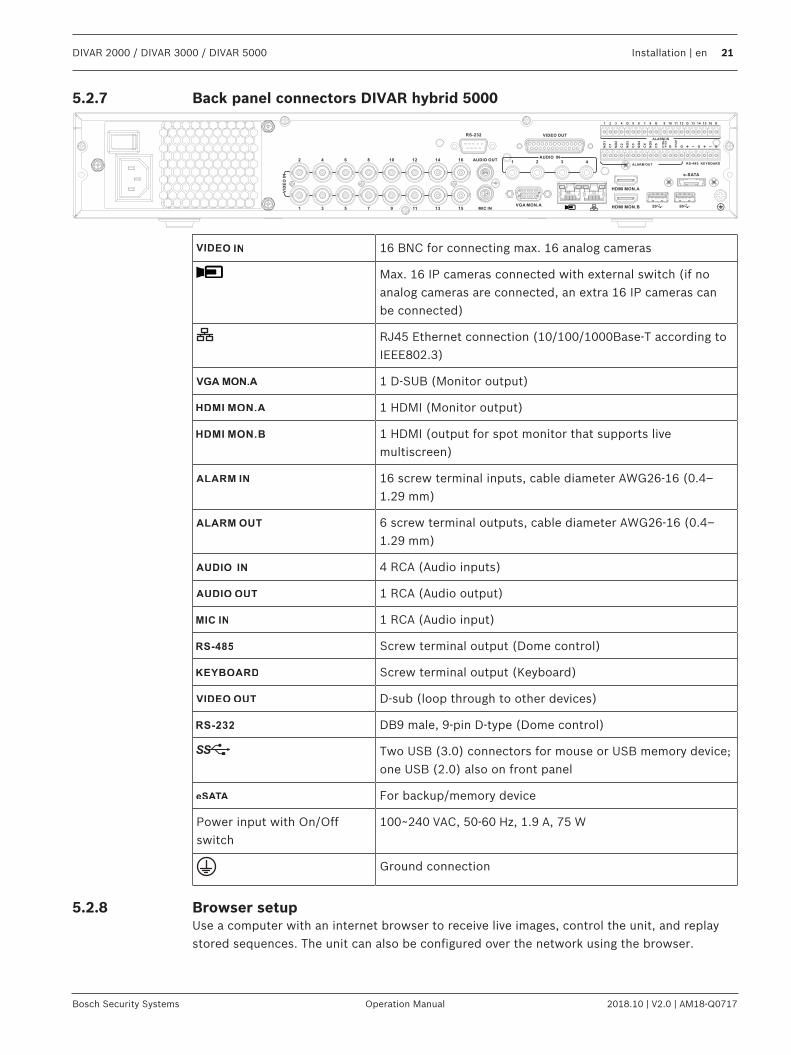
5.2.7 Back panel connectors DIVAR hybrid 5000
16 BNC for connecting max. 16 analog cameras
Max. 16 IP cameras connected with external switch (if noanalog cameras are connected, an extra 16 IP cameras canbe connected)
RJ45 Ethernet connection (10/100/1000Base-T according toIEEE802.3)
1 D-SUB (Monitor output)
1 HDMI (Monitor output)
1 HDMI (output for spot monitor that supports livemultiscreen)
16 screw terminal inputs, cable diameter AWG26‑16 (0.4–1.29 mm)
6 screw terminal outputs, cable diameter AWG26‑16 (0.4–1.29 mm)
4 RCA (Audio inputs)
1 RCA (Audio output)
1 RCA (Audio input)
Screw terminal output (Dome control)
Screw terminal output (Keyboard)
D-sub (loop through to other devices)
DB9 male, 9-pin D-type (Dome control)
Two USB (3.0) connectors for mouse or USB memory device;one USB (2.0) also on front panel
For backup/memory device
Power input with On/Offswitch
100~240 VAC, 50-60 Hz, 1.9 A, 75 W
Ground connection
5.2.8 Browser setupUse a computer with an internet browser to receive live images, control the unit, and replaystored sequences. The unit can also be configured over the network using the browser.
22 en | Installation DIVAR 2000 / DIVAR 3000 / DIVAR 5000
2018.10 | V2.0 | AM18-Q0717 Operation Manual Bosch Security Systems
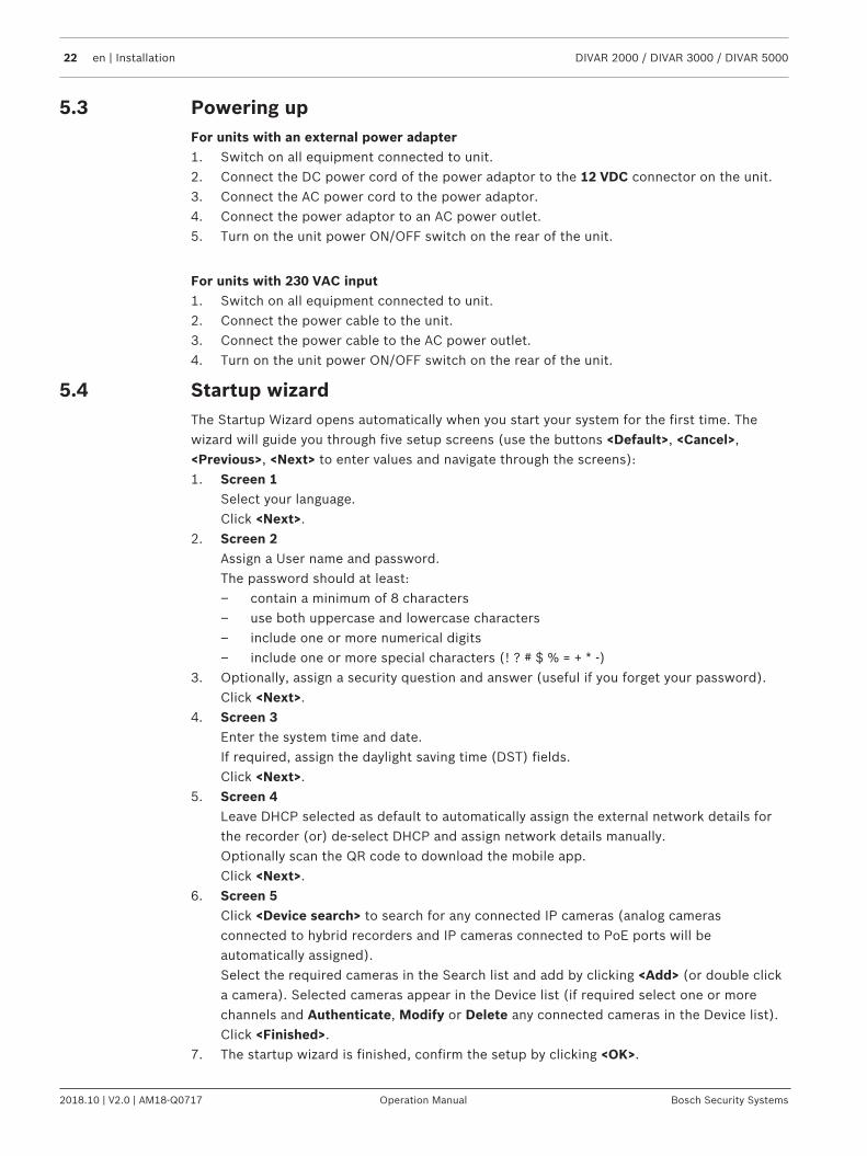
5.3 Powering upFor units with an external power adapter1. Switch on all equipment connected to unit.2. Connect the DC power cord of the power adaptor to the 12 VDC connector on the unit.3. Connect the AC power cord to the power adaptor.4. Connect the power adaptor to an AC power outlet.5. Turn on the unit power ON/OFF switch on the rear of the unit.
For units with 230 VAC input1. Switch on all equipment connected to unit.2. Connect the power cable to the unit.3. Connect the power cable to the AC power outlet.4. Turn on the unit power ON/OFF switch on the rear of the unit.
5.4 Startup wizardThe Startup Wizard opens automatically when you start your system for the first time. Thewizard will guide you through five setup screens (use the buttons <Default>, <Cancel>,<Previous>, <Next> to enter values and navigate through the screens):1. Screen 1
Select your language.Click <Next>.
2. Screen 2Assign a User name and password.The password should at least:– contain a minimum of 8 characters– use both uppercase and lowercase characters– include one or more numerical digits– include one or more special characters (! ? # $ % = + * -)
3. Optionally, assign a security question and answer (useful if you forget your password).Click <Next>.
4. Screen 3Enter the system time and date.If required, assign the daylight saving time (DST) fields.Click <Next>.
5. Screen 4Leave DHCP selected as default to automatically assign the external network details forthe recorder (or) de-select DHCP and assign network details manually.Optionally scan the QR code to download the mobile app.Click <Next>.
6. Screen 5Click <Device search> to search for any connected IP cameras (analog camerasconnected to hybrid recorders and IP cameras connected to PoE ports will beautomatically assigned).Select the required cameras in the Search list and add by clicking <Add> (or double clicka camera). Selected cameras appear in the Device list (if required select one or morechannels and Authenticate, Modify or Delete any connected cameras in the Device list).Click <Finished>.
7. The startup wizard is finished, confirm the setup by clicking <OK>.

DIVAR 2000 / DIVAR 3000 / DIVAR 5000 Installation | en 23
Bosch Security Systems Operation Manual 2018.10 | V2.0 | AM18-Q0717
Notice!Use <Cancel> to automatically install all factory defaults and exit the Startup wizard.
5.5 LoginLog in to your recorder by entering your user name and password, then click <OK>.Use the supplied USB mouse, front panel, remote control or keyboard to input data andcommands.
5.6 Logout/ShutdownQuick logoutRight-click the mouse to access the Quick menu; and choose the option Logout user.
Shutdown/Logout via Main menu1. Right-click the mouse to access the Quick menu; from here choose the option Main
menu.2. Select the Shutdown option on the Main menu.3. Use the menu to choose from the following options:
ShutdownLogout (logout user)Restart (Restart system)
4. Click <OK> to confirm the selection.
Shut down with power buttonAnother way to shut down the system is to press the power button on the front panel for atleast 3 seconds (the system will automatically backup video recordings and settings).Start up the system again (and access login screen) by briefly pressing the power button.
24 en | First time operation DIVAR 2000 / DIVAR 3000 / DIVAR 5000
2018.10 | V2.0 | AM18-Q0717 Operation Manual Bosch Security Systems
6 First time operation6.1 Live viewing mode
Once the Startup Wizard is completed, your monitor will show the live viewing mode with 1 to32 real-time images on the display (from a maximum 32 connected cameras). The system dateand time is displayed in the top right corner of the screen, and the channel ID is shown in thebottom left of each channel display.From here, use the mouse (or front panel buttons, or remote control) to control your systemvia on-screen icons and the Quick menu (accessible by right-clicking the mouse).Make any required configuration changes via the Main menu (last selection on Quick menu).– To change system date and time, use Main menu > Setting > System > Date & Time.– To modify the channel ID, see display settings (Main menu > Setting > Camera >
Configuration).– To change the camera view configuration, access the Quick menu and select View 1, 4, 8,
9, 16 or 32.If multiple channels are displayed, double-click on a particular channel to show this channel infull-screen (double-click on it again to return to multiple-channel view). The currently selectedchannel is shown with a green border.Each channel may also display one or more of the following icons:
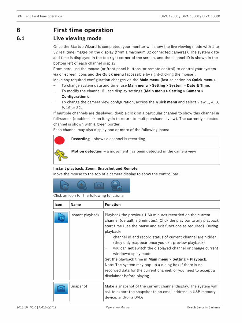
Recording – shows a channel is recording
Motion detection – a movement has been detected in the camera view
Instant playback, Zoom, Snapshot and RemoteMove the mouse to the top of a camera display to show the control bar:
Click an icon for the following functions:
Icon Name Function
Instant playback Playback the previous 1-60 minutes recorded on the currentchannel (default is 5 minutes). Click the play bar to any playbackstart time (use the pause and exit functions as required). Duringplayback:– channel id and record status of current channel are hidden
(they only reappear once you exit preview playback)– you can not switch the displayed channel or change current
window-display modeSet the playback time in Main menu > Setting > Playback.Note: The system may pop up a dialog box if there is norecorded data for the current channel, or you need to accept adisclaimer before playing.
Snapshot Make a snapshot of the current channel display. The system willask to export the snapshot to an email address, a USB memorydevice, and/or a DVD:
DIVAR 2000 / DIVAR 3000 / DIVAR 5000 First time operation | en 25
Bosch Security Systems Operation Manual 2018.10 | V2.0 | AM18-Q0717
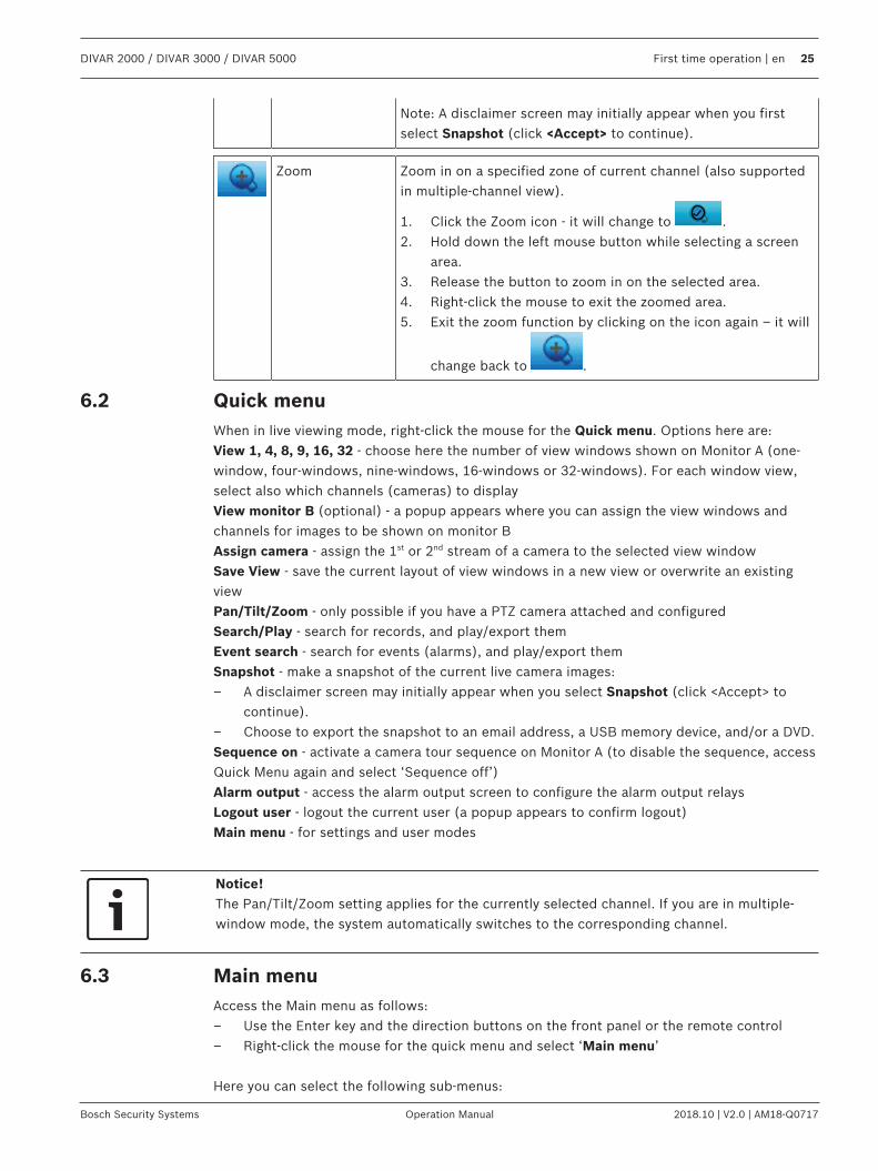
Note: A disclaimer screen may initially appear when you firstselect Snapshot (click <Accept> to continue).
Zoom Zoom in on a specified zone of current channel (also supportedin multiple-channel view).
1. Click the Zoom icon - it will change to .2. Hold down the left mouse button while selecting a screen
area.3. Release the button to zoom in on the selected area.4. Right-click the mouse to exit the zoomed area.5. Exit the zoom function by clicking on the icon again – it will
change back to .
6.2 Quick menuWhen in live viewing mode, right-click the mouse for the Quick menu. Options here are:View 1, 4, 8, 9, 16, 32 - choose here the number of view windows shown on Monitor A (one-window, four-windows, nine-windows, 16-windows or 32-windows). For each window view,select also which channels (cameras) to displayView monitor B (optional) - a popup appears where you can assign the view windows andchannels for images to be shown on monitor BAssign camera - assign the 1st or 2nd stream of a camera to the selected view windowSave View - save the current layout of view windows in a new view or overwrite an existingviewPan/Tilt/Zoom - only possible if you have a PTZ camera attached and configuredSearch/Play - search for records, and play/export themEvent search - search for events (alarms), and play/export themSnapshot - make a snapshot of the current live camera images:– A disclaimer screen may initially appear when you select Snapshot (click <Accept> to
continue).– Choose to export the snapshot to an email address, a USB memory device, and/or a DVD.Sequence on - activate a camera tour sequence on Monitor A (to disable the sequence, accessQuick Menu again and select ‘Sequence off’)Alarm output - access the alarm output screen to configure the alarm output relaysLogout user - logout the current user (a popup appears to confirm logout)Main menu - for settings and user modes
Notice!The Pan/Tilt/Zoom setting applies for the currently selected channel. If you are in multiple-window mode, the system automatically switches to the corresponding channel.
6.3 Main menuAccess the Main menu as follows:– Use the Enter key and the direction buttons on the front panel or the remote control– Right-click the mouse for the quick menu and select ‘Main menu’
Here you can select the following sub-menus:
26 en | First time operation DIVAR 2000 / DIVAR 3000 / DIVAR 5000
2018.10 | V2.0 | AM18-Q0717 Operation Manual Bosch Security Systems
– Playback to play recordings– Event search to search for events/alarms over a set period (all events can be previewed,
played and exported as required)– Export to export your recorded files to a memory device– Setting for system configuration– Info for relevant system status information– Shutdown - shutdown or restart your system, plus logout
DIVAR 2000 / DIVAR 3000 / DIVAR 5000 Hardware setup | en 27
Bosch Security Systems Operation Manual 2018.10 | V2.0 | AM18-Q0717
7 Hardware setupThis chapter contains detailed information about the hardware installation and connection ofexternal equipment to the unit. The connector types and their pin signals are described. Mostof the connectors are located at the rear panel of the unit. For convenience, one USB port islocated on the front of the unit to connect a mouse or memory device.All the input/output ports are Safety Extra Low Voltage (SELV) circuits. SELV circuits shouldonly be connected to other SELV circuits.
7.1 Keyboard connection (only DIVAR 5000 models)Use the keyboard connection on the back of the unit to connect a Bosch Intuikey keyboardusing one of the following methods:– use the supplied RJ11 adaptor – see Connect using RJ11 adapter– strip the keyboard cable (or equivalent cable) to connect leads directly – see Connect
wires directlyFor short distances (up to 30 m), standard 6-core telecom flat cable can be used to supplysignal connections for the keyboard (LTC 8558/00). Always use the Keyboard Extension Kit(LTC 8557) for distances over 30 m between the keyboard and the DVR; this kit providesjunction boxes and cables. Maximum cable length: 30 m (using standard 6-core telecom flatcable), or 1.5 km (using Belden 8760 or equivalent).The appropriate power supply (11 - 12.6 VDC, maximum 400 mA) to externally power thekeyboard must be purchased separately.
28 en | Hardware setup DIVAR 2000 / DIVAR 3000 / DIVAR 5000
2018.10 | V2.0 | AM18-Q0717 Operation Manual Bosch Security Systems
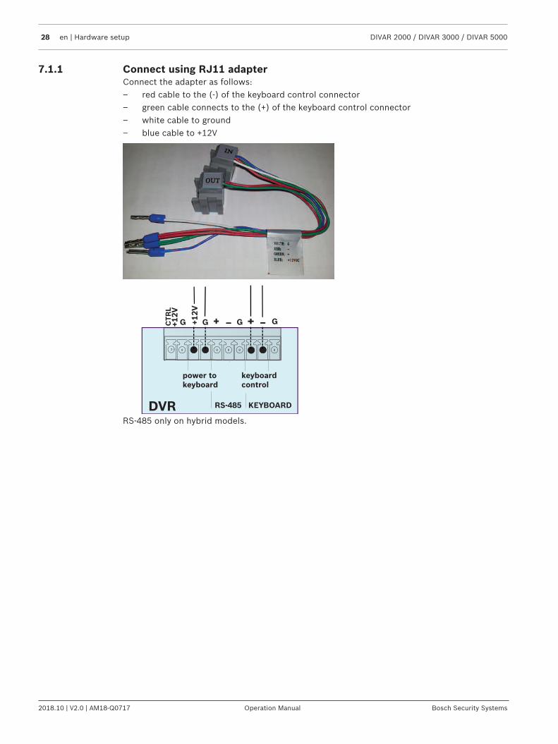
7.1.1 Connect using RJ11 adapterConnect the adapter as follows:– red cable to the (-) of the keyboard control connector– green cable connects to the (+) of the keyboard control connector– white cable to ground– blue cable to +12V
RS-485 KEYBOARD
power tokeyboard
keyboardcontrol
G + _G G+ _G+12V
CTR
L+12V
DVRRS-485 only on hybrid models.
DIVAR 2000 / DIVAR 3000 / DIVAR 5000 Hardware setup | en 29
Bosch Security Systems Operation Manual 2018.10 | V2.0 | AM18-Q0717
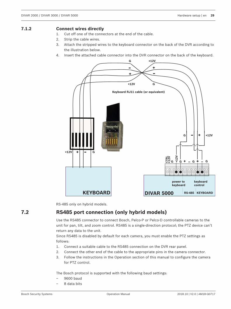
7.1.2 Connect wires directly1. Cut off one of the connectors at the end of the cable.2. Strip the cable wires.3. Attach the stripped wires to the keyboard connector on the back of the DVR according to
the illustration below.4. Insert the attached cable connector into the DVR connector on the back of the keyboard.
RS-485 KEYBOARD
power tokeyboard
keyboardcontrol
+12V
Keyboard RJ11 cable (or equivalent)
G
G + _G G+ _G+12V
CTR
L+12V
_+
DIVAR 5000KEYBOARD
+12V +_
G
+12V
G
G
+12V
_+
+
_
RS-485 only on hybrid models.
7.2 RS485 port connection (only hybrid models)Use the RS485 connector to connect Bosch, Pelco-P or Pelco-D controllable cameras to theunit for pan, tilt, and zoom control. RS485 is a single-direction protocol; the PTZ device can’treturn any data to the unit.Since RS485 is disabled by default for each camera, you must enable the PTZ settings asfollows:1. Connect a suitable cable to the RS485 connection on the DVR rear panel.2. Connect the other end of the cable to the appropriate pins in the camera connector.3. Follow the instructions in the Operation section of this manual to configure the camera
for PTZ control.
The Bosch protocol is supported with the following baud settings:– 9600 baud– 8 data bits
30 en | Hardware setup DIVAR 2000 / DIVAR 3000 / DIVAR 5000
2018.10 | V2.0 | AM18-Q0717 Operation Manual Bosch Security Systems
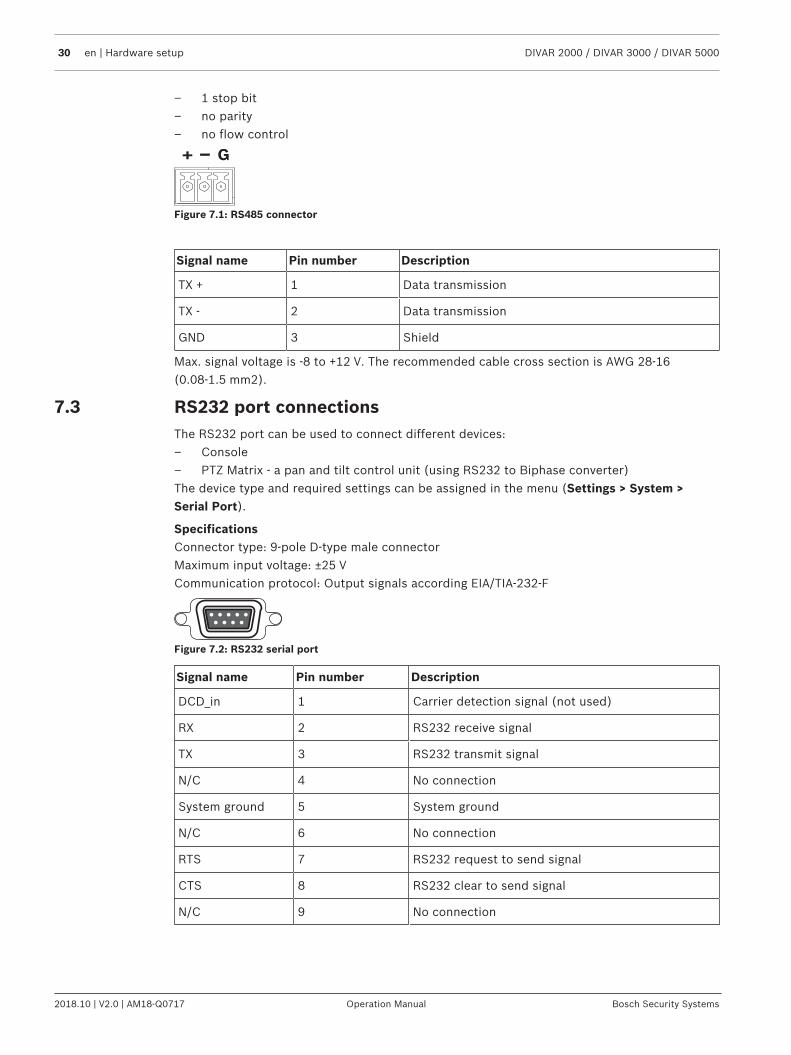
– 1 stop bit– no parity– no flow control
Figure 7.1: RS485 connector
Signal name Pin number Description
TX + 1 Data transmission
TX - 2 Data transmission
GND 3 Shield
Max. signal voltage is -8 to +12 V. The recommended cable cross section is AWG 28-16(0.08-1.5 mm2).
7.3 RS232 port connectionsThe RS232 port can be used to connect different devices:– Console– PTZ Matrix - a pan and tilt control unit (using RS232 to Biphase converter)The device type and required settings can be assigned in the menu (Settings > System >Serial Port).
SpecificationsConnector type: 9-pole D-type male connectorMaximum input voltage: ±25 VCommunication protocol: Output signals according EIA/TIA-232-F
Figure 7.2: RS232 serial port
Signal name Pin number Description
DCD_in 1 Carrier detection signal (not used)
RX 2 RS232 receive signal
TX 3 RS232 transmit signal
N/C 4 No connection
System ground 5 System ground
N/C 6 No connection
RTS 7 RS232 request to send signal
CTS 8 RS232 clear to send signal
N/C 9 No connection
DIVAR 2000 / DIVAR 3000 / DIVAR 5000 Hardware setup | en 31
Bosch Security Systems Operation Manual 2018.10 | V2.0 | AM18-Q0717
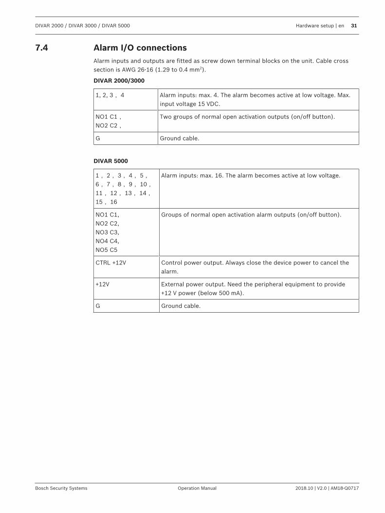
7.4 Alarm I/O connectionsAlarm inputs and outputs are fitted as screw down terminal blocks on the unit. Cable crosssection is AWG 26-16 (1.29 to 0.4 mm2).
DIVAR 2000/3000
1, 2, 3, 4 Alarm inputs: max. 4. The alarm becomes active at low voltage. Max.input voltage 15 VDC.
NO1 C1,NO2 C2,
Two groups of normal open activation outputs (on/off button).
G Ground cable.
DIVAR 5000
1, 2, 3, 4, 5,6, 7, 8, 9, 10,11, 12, 13, 14,15, 16
Alarm inputs: max. 16. The alarm becomes active at low voltage.
NO1 C1,NO2 C2,NO3 C3,NO4 C4,NO5 C5
Groups of normal open activation alarm outputs (on/off button).
CTRL +12V Control power output. Always close the device power to cancel thealarm.
+12V External power output. Need the peripheral equipment to provide+12 V power (below 500 mA).
G Ground cable.
32 en | Settings DIVAR 2000 / DIVAR 3000 / DIVAR 5000
2018.10 | V2.0 | AM18-Q0717 Operation Manual Bosch Security Systems
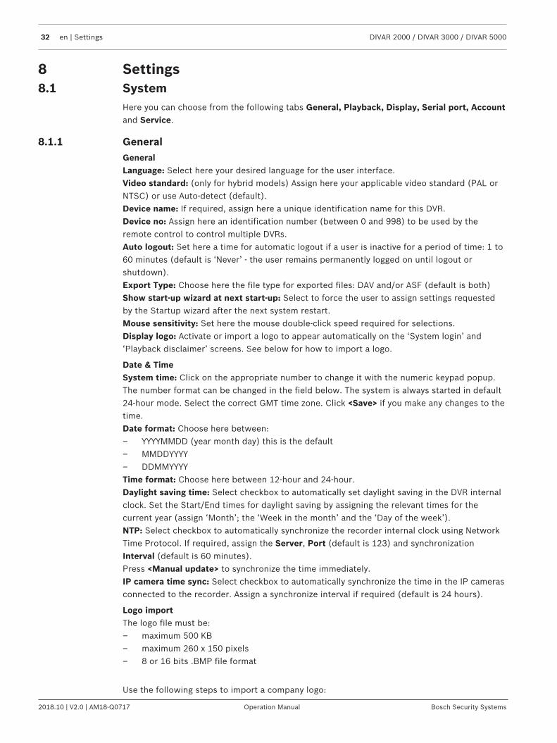
8 Settings8.1 System
Here you can choose from the following tabs General, Playback, Display, Serial port, Accountand Service.
8.1.1 GeneralGeneralLanguage: Select here your desired language for the user interface.Video standard: (only for hybrid models) Assign here your applicable video standard (PAL orNTSC) or use Auto-detect (default).Device name: If required, assign here a unique identification name for this DVR.Device no: Assign here an identification number (between 0 and 998) to be used by theremote control to control multiple DVRs.Auto logout: Set here a time for automatic logout if a user is inactive for a period of time: 1 to60 minutes (default is ‘Never’ - the user remains permanently logged on until logout orshutdown).Export Type: Choose here the file type for exported files: DAV and/or ASF (default is both)Show start-up wizard at next start-up: Select to force the user to assign settings requestedby the Startup wizard after the next system restart.Mouse sensitivity: Set here the mouse double-click speed required for selections.Display logo: Activate or import a logo to appear automatically on the ‘System login’ and‘Playback disclaimer’ screens. See below for how to import a logo.
Date & TimeSystem time: Click on the appropriate number to change it with the numeric keypad popup.The number format can be changed in the field below. The system is always started in default24-hour mode. Select the correct GMT time zone. Click <Save> if you make any changes to thetime.Date format: Choose here between:– YYYYMMDD (year month day) this is the default– MMDDYYYY– DDMMYYYYTime format: Choose here between 12-hour and 24-hour.Daylight saving time: Select checkbox to automatically set daylight saving in the DVR internalclock. Set the Start/End times for daylight saving by assigning the relevant times for thecurrent year (assign ‘Month’; the ‘Week in the month’ and the ‘Day of the week’).NTP: Select checkbox to automatically synchronize the recorder internal clock using NetworkTime Protocol. If required, assign the Server, Port (default is 123) and synchronizationInterval (default is 60 minutes).Press <Manual update> to synchronize the time immediately.IP camera time sync: Select checkbox to automatically synchronize the time in the IP camerasconnected to the recorder. Assign a synchronize interval if required (default is 24 hours).
Logo importThe logo file must be:– maximum 500 KB– maximum 260 x 150 pixels– 8 or 16 bits .BMP file format
Use the following steps to import a company logo:
DIVAR 2000 / DIVAR 3000 / DIVAR 5000 Settings | en 33
Bosch Security Systems Operation Manual 2018.10 | V2.0 | AM18-Q0717
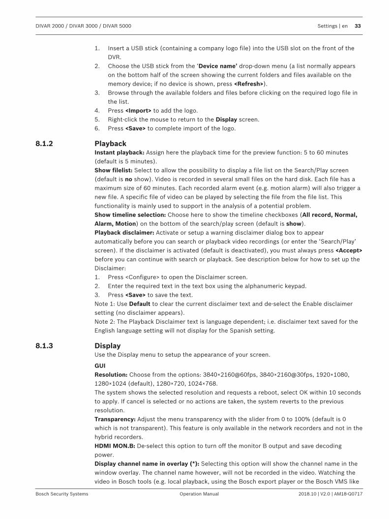
1. Insert a USB stick (containing a company logo file) into the USB slot on the front of theDVR.
2. Choose the USB stick from the ‘Device name’ drop-down menu (a list normally appearson the bottom half of the screen showing the current folders and files available on thememory device; if no device is shown, press <Refresh>).
3. Browse through the available folders and files before clicking on the required logo file inthe list.
4. Press <Import> to add the logo.5. Right-click the mouse to return to the Display screen.6. Press <Save> to complete import of the logo.
8.1.2 PlaybackInstant playback: Assign here the playback time for the preview function: 5 to 60 minutes(default is 5 minutes).Show filelist: Select to allow the possibility to display a file list on the Search/Play screen(default is no show). Video is recorded in several small files on the hard disk. Each file has amaximum size of 60 minutes. Each recorded alarm event (e.g. motion alarm) will also trigger anew file. A specific file of video can be played by selecting the file from the file list. Thisfunctionality is mainly used to support in the analysis of a potential problem.Show timeline selection: Choose here to show the timeline checkboxes (All record, Normal,Alarm, Motion) on the bottom of the search/play screen (default is show).Playback disclaimer: Activate or setup a warning disclaimer dialog box to appearautomatically before you can search or playback video recordings (or enter the ‘Search/Play’screen). If the disclaimer is activated (default is deactivated), you must always press <Accept>before you can continue with search or playback. See description below for how to set up theDisclaimer:1. Press <Configure> to open the Disclaimer screen.2. Enter the required text in the text box using the alphanumeric keypad.3. Press <Save> to save the text.Note 1: Use Default to clear the current disclaimer text and de-select the Enable disclaimersetting (no disclaimer appears).Note 2: The Playback Disclaimer text is language dependent; i.e. disclaimer text saved for theEnglish language setting will not display for the Spanish setting.
8.1.3 DisplayUse the Display menu to setup the appearance of your screen.
GUIResolution: Choose from the options: 3840×2160@60fps, 3840×2160@30fps, 1920×1080,1280×1024 (default), 1280×720, 1024×768.The system shows the selected resolution and requests a reboot, select OK within 10 secondsto apply. If cancel is selected or no actions are taken, the system reverts to the previousresolution.Transparency: Adjust the menu transparency with the slider from 0 to 100% (default is 0which is not transparent). This feature is only available in the network recorders and not in thehybrid recorders.HDMI MON.B: De-select this option to turn off the monitor B output and save decodingpower.Display channel name in overlay (*): Selecting this option will show the channel name in thewindow overlay. The channel name however, will not be recorded in the video. Watching thevideo in Bosch tools (e.g. local playback, using the Bosch export player or the Bosch VMS like

34 en | Settings DIVAR 2000 / DIVAR 3000 / DIVAR 5000
2018.10 | V2.0 | AM18-Q0717 Operation Manual Bosch Security Systems
BVC and BVMS) can still enable the overlay on the video. Exporting the video to a 3rd partyformat like AVI or MPEG however, will not show the channel overlay anymore. Use this optionif you want to be able to dynamically turn the channel name on and off. Please note that alldisplay options will always be applied to all cameras.Display and store channel name in video (*): Selecting this option will record the channelname inside the video. This channel name will always be there, also when exporting the videoto a 3rd party format like AVI or MPEG. It will not be possible to hide the channel name, alsonot in Bosch tooling. Use this option if you want the channel name to permanently becomepart of the video. Please note that all display options will always be applied to all cameras.Camera name stamping: Choose the location of the camera name stamp: Top, Bottom orCustom (set by entering the X/Y coordinates).Display time in overlay (*): Selecting this option will show the current time in the windowoverlay. This option is subject to the same conditions as "Display channel name in overlay".Display and store time in video (*): Selecting this option to store the time in the video. Thisoption is subject to the same conditions as "Display and store channel name in video".Time stamping: Choose the location of the time stamp: Top, Bottom or Custom (set byentering the X/Y coordinates).Display milliseconds (*): Select to show milliseconds on the time stamp.Display system time: Select to show the general system time in the top right of the monitor.Hide event and status indicator for covert cameras: Select to hide the indicators on covertcameras. Enabling this function hides the recording status icon as well as all potential alarmicons. Enabling this also means that it will not be possible in live mode to see if the camera isstill recording or if any events occurred. Use this option to ensure that the covert window iscompletely black so that no one knows this camera exists.
Notice!(*)This configuration option is only available for Bosch cameras and not for 3rd party ONVIFcameras.
ViewsThe views menu can be used to modify the default lay-outs and create your own favorite views.It’s possible to assign different cameras to views as well as to switch between the 1st and 2nd
stream of the camera.Using a system with a lot of cameras creates a high load on the performance of the system.Specifying the 2nd stream in multi-channel (such as 8CH/16CH) views may help reduce thestress on the system. In case the current camera set-up reaches its encoding limit (16 x1080p), the system may run into a situation where channels can’t display the video. Forexample, if there are eight 5MP cameras in the system, the system can’t show all of them atthe same time. Some windows will show an “out of decode” error message. Using the 2nd
stream, which generally streams at a lower resolution, still allows you to display video of alleight cameras at the same time in live mode, while still recording the high quality 5MPstreams.Please note that a view can also be modified and saved directly from the live view using thequick menu and its assign camera and save view option.View mode: The system has 6 different view modes (1, 4, 8, 9, 16 or 32 windows). For eachmode, there are standard lay-outs. These standard lay-outs can be modified and new lay-outscan be created and saved.
DIVAR 2000 / DIVAR 3000 / DIVAR 5000 Settings | en 35
Bosch Security Systems Operation Manual 2018.10 | V2.0 | AM18-Q0717
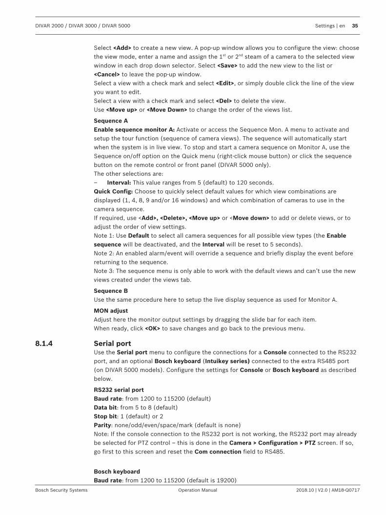
Select <Add> to create a new view. A pop-up window allows you to configure the view: choosethe view mode, enter a name and assign the 1st or 2nd steam of a camera to the selected viewwindow in each drop down selector. Select <Save> to add the new view to the list or<Cancel> to leave the pop-up window.Select a view with a check mark and select <Edit>, or simply double click the line of the viewyou want to edit.Select a view with a check mark and select <Del> to delete the view.Use <Move up> or <Move Down> to change the order of the views list.
Sequence AEnable sequence monitor A: Activate or access the Sequence Mon. A menu to activate andsetup the tour function (sequence of camera views). The sequence will automatically startwhen the system is in live view. To stop and start a camera sequence on Monitor A, use theSequence on/off option on the Quick menu (right-click mouse button) or click the sequencebutton on the remote control or front panel (DIVAR 5000 only).The other selections are:– Interval: This value ranges from 5 (default) to 120 seconds.Quick Config: Choose to quickly select default values for which view combinations aredisplayed (1, 4, 8, 9 and/or 16 windows) and which combination of cameras to use in thecamera sequence.If required, use <Add>, <Delete>, <Move up> or <Move down> to add or delete views, or toadjust the order of view settings.Note 1: Use Default to select all camera sequences for all possible view types (the Enablesequence will be deactivated, and the Interval will be reset to 5 seconds).Note 2: An enabled alarm/event will override a sequence and briefly display the event beforereturning to the sequence.Note 3: The sequence menu is only able to work with the default views and can’t use the newviews created under the views tab.
Sequence BUse the same procedure here to setup the live display sequence as used for Monitor A.
MON adjustAdjust here the monitor output settings by dragging the slide bar for each item.When ready, click <OK> to save changes and go back to the previous menu.
8.1.4 Serial portUse the Serial port menu to configure the connections for a Console connected to the RS232port, and an optional Bosch keyboard (Intuikey series) connected to the extra RS485 port(on DIVAR 5000 models). Configure the settings for Console or Bosch keyboard as describedbelow.
RS232 serial portBaud rate: from 1200 to 115200 (default)Data bit: from 5 to 8 (default)Stop bit: 1 (default) or 2Parity: none/odd/even/space/mark (default is none)Note: If the console connection to the RS232 port is not working, the RS232 port may alreadybe selected for PTZ control – this is done in the Camera > Configuration > PTZ screen. If so,go first to this screen and reset the Com connection field to RS485.
Bosch keyboardBaud rate: from 1200 to 115200 (default is 19200)
36 en | Settings DIVAR 2000 / DIVAR 3000 / DIVAR 5000
2018.10 | V2.0 | AM18-Q0717 Operation Manual Bosch Security Systems
Data bit: from 5 to 8 (default)Stop bit: 1/2 (default is 1)Parity: none/odd/even/space/mark (default is none)Keyboard address: (default is 1) One Intuikey keyboard can communicate with a maximum 16DIVARs. If assigning multiple DIVARs to a keyboard, Set the Keyboard address for everyDIVAR.First camera offset: (default is 1) Set this offset for every DIVAR. Camera 1 of the DIVAR willbe called on the keyboard by selecting the programmed ‘First camera offset’ number. Forexample, set the offset to 101 so when you select 101, camera 1 is displayed in full screen onmonitor A of that selected DIVAR. Press 112 to display camera 12 in full screen.Press <Save> to enter changes and go back to the previous menu.
8.1.5 Text/Pos (only on hybrid recorders)With Text/Pos you can add text and information to the image. It includes information analysisand title overlay function. The Sniffer mode can be either COM (RS232) or NET (IP network).
Sniffer mode COMFor RS232 port settings see Serial port, page 35.– Overlay position: Choose Top left, Bottom left, Top right, Bottom right.– Overlay mode: Choose from:
– Local – displays the overlay in the image in the local monitor video– Remote – stores/records the overlay in the recorded file
– Overlay channel: select the channel to add the overlay to.
Sniffer mode NET– Overlay position: Choose Top left, Bottom left, Top right, Bottom right.– Overlay mode: Choose from:
– Local – displays the overlay in the image in the local monitor video– Remote – stores/records the overlay in the recorded file
– Bridge id: Choose an ID from 1 to 16. Under each ID you make these selections:– Bridge ip: select the destination ports. If required, you can change the corresponding
Service port number– Host ip: select the destination ports. If required, you can change the corresponding
Recorder port number– ATM/POS import: select 1 of the 4 imports.– Overlay channel: select the channel to add the overlay to. You can use each channel
only once.
8.1.6 AccountThis screen lists all of the user accounts for this recorder. Each account level is set withindividual user rights and limited by a password. If you have ‘administrator’ rights, you canadd, delete and modify user account (except your own) - see descriptions below.Use <Move up> and <Move down> to change the order in which the users appear in the‘Accounts’ (this also determines the order of users in the Login menu).
Add userSelect <Add user>.1. Enter a User name up to 16 characters.2. Enter a Password and Confirm password by entering it again.
The password should at least:

DIVAR 2000 / DIVAR 3000 / DIVAR 5000 Settings | en 37
Bosch Security Systems Operation Manual 2018.10 | V2.0 | AM18-Q0717
– contain a minimum of 8 characters– use both uppercase and lowercase characters– include one or more numerical digits– include one or more special characters (! ? # $ % = + * -)
3. If required, enter a security question and answer to help prompt the password if youforget it later.
4. Manually select the authority fields required for the new user type for all tabs (System,Live, Playback).
5. Select <Save> when done.
DeleteDelete an Account as follows:1. Click <X> in the ‘Delete’ column for the Account to be deleted2. Confirm the delete by clicking <Yes>.
Modify an account password (or security question)1. Select the pencil icon beside the relevant Account name on the list (a new screen
appears with selection fields for changing password and user authorities).2. Select Modify password.3. Enter the Old password.4. Enter the New password.5. Enter the new password again in the Confirm password field.6. If required, enter a new Question and Answer for the password security field:
Choose a question from the pull-down list (or enter your own customized question).Enter the appropriate answer.
7. Click <Save> to save the new password settings.
Modify account authority1. Select the pencil icon beside the relevant Account name on the list (a new screen
appears with selection fields for changing password and user authorities).2. Change the user authority by (de)selecting the check boxes.3. Click <Save>.
8.1.7 ServiceUpgrade firmwareUpgrade the system firmware in 2 ways:
Via the Bosch download store (an open internet connection is required):1. View the current firmware version of your installed system2. Check the Bosch download store if new versions are available3. Upgrade to a new version if required.
Via the USB slot:1. Insert a USB stick with a preloaded update file (must be called xxx.bin).2. Click <Upgrade>.3. Select the update file.4. Click <Start>to begin the update.5. Wait until the update is complete and the system is restarted.
38 en | Settings DIVAR 2000 / DIVAR 3000 / DIVAR 5000
2018.10 | V2.0 | AM18-Q0717 Operation Manual Bosch Security Systems
Notice!Bosch strongly recommends upgrading to the latest firmware for the best possiblefunctionality, compatibility, performance and security.Check http://downloadstore.boschsecurity.com/ regularly to see if there is a new firmwareversion available.
ConfigHere you can import or export (backup) configuration settings:Import1. Choose a memory device from the drop-down menu (a list normally appears of previously
saved system settings available on the device).2. Select the required config files from the list.3. Click <Import> to load the files.Export1. Choose the device to export to.2. Check there is sufficient space on the device.3. Use the selection buttons (on the bottom of the screen) for your configuration backup:
– New folder will create a new folder on the selected memory device– Format will ask to confirm a format of the selected memory device.– Import configuration– Export configuration saves a copy of the system settings to a selected memory
device
Default
Notice!User settings and recordings will be lostThe system menu display, language, time display mode, video format, IP address andrecordings will all lose their user defined setup after the factory defaults are restored.
Reset menu defaultsUse this option to restore specific parts of the configuration to defaults. This option will onlyreset the corresponding settings for the selected menu to its default settings.1. Select the check boxes for the menus you wish to reset.2. Click <Save> or <Apply>.Reset complete system to factory defaults<Save>Use this option to reset the complete device to factory defaults. Please note that this will alsodelete all recordings and remove any loaded certificates from the system.1. Click <Reset> (you may need to enter a Password to confirm the restore).
DIVAR 2000 / DIVAR 3000 / DIVAR 5000 Settings | en 39
Bosch Security Systems Operation Manual 2018.10 | V2.0 | AM18-Q0717
8.2 Network
8.2.1 ConnectionFour extra tabs are available (External, Internal, Port, Streaming).In a typical installation the external and internal network are clearly divided. IP cameras areconnected to the internal network and/or PoE ports of the recorder which makes themisolated from the rest of the network/internet. The external network port is then used toconnect the recorder to the general network or public internet. Of course there may be goodreasons to differentiate in the network setup.In any network setup, it is important to note that the external and internal network of therecorder are not internally connected / looped-through. This means these are really twoseparate networks which can’t communicate directly with each other. It’s therefore mandatorythat the external and internal network must fall into a different IP range / subnet if both ofthem are used. Without this separation the recorder would not know to which networkconnection to send any incoming traffic.
ExternalInput here the following information for connecting the recorder to a public outside network:MTU: Maximum transmission unit in bytes unit for used ports (default is 1500).IP version: IPv4 (default) or IPv6. This is the IP address access format.DHCP (only for IPv4 option): Select this to automatically search for IP details. If this field isenabled, you cannot modify IP / Subnet mask / Gateway and these values are displayed aszero (if PPPoE is operating, you also cannot modify IP/Subnet mask /Gateway). To view thecurrent IP information, you first need to disable the DHCP function.Link address (only for IPv6 option): Network address that is valid only for communicationswithin the network segment (link) or the broadcast domain that the host is connected to.IP address: Enter here your IP address. (For the IPv6 version, default gateway, preferred DNSand alternate DNS, the default value shall be 64-digit).Subnet mask (only for IPv4 option): Enter here your subnet mask addressDefault gateway: If required, enter here the default gateway address.
Notice!Addresses and maximum connectionsThe system needs to check the validity of all IPv6 addresses. The IP address and the defaultgateway must be the same in each IP section (i.e. the specified length of the subnet prefixmust have the same string). The maximum number of connections is 64, however thebandwidth is limited. Bosch strongly advises not using more than 4 simultaneous connectionsstreaming video at the same time.
Preferred DNS: if required, enter here the preferred DNS server IP address.Alternate DNS: if required, enter here an alternative DNS server address.When ready, click <Save> to enter values and go back to the previous menu.
InternalChoose here the settings for connecting cameras to the recorder in a closed internal network(DHCP or as a DHCP switch).
40 en | Settings DIVAR 2000 / DIVAR 3000 / DIVAR 5000
2018.10 | V2.0 | AM18-Q0717 Operation Manual Bosch Security Systems
Using the DHCP option, the recorder will act as a normal network device. The IP can beconfigured manually or an IP address will be automatically assigned by a DHCP server if theDHCP checkbox is ticked. This option is normally used for devices where the recorder andcameras are in a separate internal network and the IP allocation is arranged outside of therecorder.With Use this device as a DHCP switch selected, the recorder will function as a DHCP server.This means the recorder will assign an IP address to any device that is connected to itsnetwork. This option is generally used when the cameras are connected to the PoE ports ofthe recorder or when the recorder is expected to manage the IP addresses in the internalnetwork.Both options have the same settings. Please note that for the DHCP server option, the IPaddresses will be assigned in the IP address range specified in this section.IP address: Enter here your IP address.Subnet mask: (only for IPv4 option): Enter here your subnet mask addressDefault gateway: If required, enter here the default gateway address.
PortGo to your router that connects your recorder to the internet and forward thesecommunication ports: HTTPS, RTSP and TCP. If you plan to connect through HTTP as well,forward the HTTP port in your router. Bosch advises to use only HTTPS connections for ahigher security. Read your router manual for instructions to forward ports to a device.TCP port: Default is 37777. This port is used by the Bosch DIVAR Mobile Viewer to connect tothe recorder with mobile phones.UDP port: Default is 37778.HTTP port: Default is 80. This port can be disabled to prevent any remote access to therecorder through HTTP traffic. Allowing only HTTPS connections to the recorder grants a muchstronger security and Bosch strongly recommends to only use HTTPS communication.However, if the network bandwidth is limited, the system has a very high load (e.g. 32connected cameras) or the remote workstations are not powerful enough, the HTTPconnection can be used to increase the systems performance and reduce network bandwidthstress.HTTPS port: Default is 443.RTSP port: (Default is 554). When setting up RTSP streaming, use the following URL format:rtsp://<username>:<password>@<ip>:<port>/cam/realmonitor?channel=<channelNo>&subtype=<typeNo> e.g.: rtsp://ADMINISTRATOR:[email protected]/cam/realmonitor?channel=1&subtype=0username = usernamepassword = passwordport = default is 554 (this is optional)channel = channel number 1..16subtype = 0 or 1 (1st or 2nd stream)
Notice!RebootThe system always needs to reboot if any of the above ports are changed. Make sure the portvalues here do not conflict.
StreamingChoose your preferred Live Video Stream Buffering:
DIVAR 2000 / DIVAR 3000 / DIVAR 5000 Settings | en 41
Bosch Security Systems Operation Manual 2018.10 | V2.0 | AM18-Q0717
– Realtime– Balanced– Network optimized– Custom - set here your preferred streaming buffer (minimum 200 ms, maximum 2000 ms,
default 500 ms)The buffer size increases from 'Realtime' to 'Balanced' to 'Network optimized'. 'Realtime' usesa minimum buffer to minimize latency. If your video stream has a high bit-rate, the video maynot run smooth in live mode. To get a smoother video, you can increase the buffer by selecting'Balanced' or 'Network optimized'. But this will increase the latency. In general, Boschrecommends to use the network optimized option to guarantee a fluent stream. However, ifPTZ cameras are installed and frequently operated, it’s better to use the 'Realtime' mode toensure a smooth control of the domes.Please note that these settings only apply to the recorders local live mode. The settings haveno impact on the recorded video or on remote live streaming. If there are issues with fluentremote live streams, consider using the 2nd stream with lower bandwidth requirements.
8.2.2 DDNSMake sure the recorder is connected to the open internet, before you configure the DDNSservice.Use these steps to configure DDNS:1. Select the ‘Enable’ box.2. Select DDNS provider(s) from the drop-down menu. More DDNS types can be used at the
same time; you only need to select the required type. These providers are supported:– Bosch remote portal (see Notice)– NO-IP DDNS– Dyndns DDNS
Notice!Bosch remote portalThe Bosch remote portal is a free DDNS service by Bosch. You can apply for an account if youselect "Bosch Remote Portal" in the DDNS menu on the recorder, and fill in the boxes asdescribed below this notice. Use a valid email address to apply for this. After this application,the email address is the account name for your DDNS service. You can use multiple recorderson the same account. Just fill in on each recorder your email address in the <Account> box,your password and use different domain names for each recorder.Your DDNS registration is activated immediately, but needs email confirmation. To confirmyour DDNS registration, click on the link in the email you receive. If you do not confirm theaccount, the DDNS registration is cancelled.
If you select Bosch remote portal:1. Fill in the details for the unique Domain name you want to use. Your domain name is a
subdomain below boschremoteconnect.com. If the device is correctly connected to theinternet, the dropdown box shows the available subdomain name (e.g.boschremoteconnect.com)
2. Fill in a valid email address in the <Account> box and a correct password. Your account isyour email address. See Notice above.– If you already have an account, use the information from this account.– If you create a new account, you must choose a new password. Use a strong
password! Confirm the password in the next field.
42 en | Settings DIVAR 2000 / DIVAR 3000 / DIVAR 5000
2018.10 | V2.0 | AM18-Q0717 Operation Manual Bosch Security Systems
3. Select the ‘I agree to … ‘ boxes after you read and approved the terms and conditions andprivacy statement.
4. Click <Apply> to register your domain name5. You can use your domain name immediately. If you created a new account, you must
confirm your DDNS registration by clicking the validation link in the email you receive.After registration, you can manage your DDNS accounts on https://remote.boschsecurity.com
If you select another DDNS provider:1. Fill in the details for the Domain as assigned by the provider.2. Fill in your user name and password.3. In the "Interval" box, fill in the interval time between the updates of your IP address to
the DDNS provider.
8.2.3 MobileUse this page to scan the relevant QR codes for downloading the IOS or Android apps foroperating your DIVAR. Once the app is downloaded, scan the relevant QR code to add thedevice through its Local IP (if connected to a WiFi network) or remote IP / DDNS name (ifconnected to the public internet).
8.2.4 BandwidthUse this option if the external connection of the recorder is connected to a limited networkbandwidth. A typical use case can be to restrict the bandwidth the recorder may use tocontrol the stress on the network and prevent the recorder absorbing all available networkbandwidth and preventing other systems from working.Apart from ensuring that the bandwidth will not exceed the configured value, the remoteclients will also behave differently. BVC for example will always request the 2nd stream bydefault in live mode and the playback will only stream I-Frames only (1 picture every second)on half speed to reduce the network stress. Setting the remote client in pause mode will loadall frames for watching the complete video. Of course exporting the video will always exportall frames as well.– Bandwidth limit speed: Default is No (there is no bandwidth limit active)
The bandwidth limits the traffic from the DVR to each client where each connectionindividually may not exceed the configured bandwidth. If bandwidth is set to a value, thedefault bandwidth limit only applies to network connections outside the subnet of theDVR (WAN). Bandwidth limit does NOT apply to network connection on the same subnetas the DVR (LAN). Note: IP addresses starting in the range of 10.0.0.0 to 10.255.255.255, and 172.16.0.0 to172.31.255.255, and 192.168.0.0 to 192.168.255.255 are always considered LANaddresses.
The default settings can be overruled by using the <Add> button to add IP address rangesin ‘Subnet never limited’ or in ‘Subnet always limited’ (it is not possible to enter thesame IP address in both fields). Select a checkbox in front of an IP address and press<Delete> to remove an IP range from the list; use <Default> to return all default settings.When ready, click <Save> to save settings and return to previous menu.DVR will check automatically if a BVC or Web Client network connection request is sentfrom a PC located in the field ‘Subnet never limited’ or in ‘Subnet always limited’.
This means that, when the bandwidth limitation is active, it will be limited to the selectedbandwidth setting. For example, if bandwidth limitation is set to 256 Kbps, then network
DIVAR 2000 / DIVAR 3000 / DIVAR 5000 Settings | en 43
Bosch Security Systems Operation Manual 2018.10 | V2.0 | AM18-Q0717
traffic to these limited IP connections will not exceed 256 Kbps. When the bandwidth limit is set to a value, the encoding settings for the 2nd stream willbe optimized to stream live video for the selected bandwidth value - see below.
– Bandwidth limit clients: Default is 1.Choose here the number of ‘bandwidth-limited’ clients (max. 4) that are allowed in thebandwidth limit configuration. Every ‘bandwidth-limited’ connection used is maximized tothe configured maximum. For example if max bandwidth usage is set to 256Kbps and the‘bandwidth-limited’ clients value is 4, then the total bandwidth consumption can be 1M.A maximum 64 ‘remote’ client connections are possible, however more than 4 remoteclients can lead to performance limitations. If the maximum available bandwidth forstreaming is used (60Mbit/s) - users can still login, but will not receive a video streamuntil bandwidth is available again
8.2.5 UPnPThis protocol enables a mapping relationship between the LAN and the WAN:– Enable or disable the UPnP function on this device– Status – Can be Disable, Success, Searching or Unknown (when the system is offline)– Router LAN IP– Router WAN IPThe bottom table shows the PAT (port mapping list) with a one-to-one relationship with therouter port mapping setting:1. Double-click a port to change a setting2. Click <OK> when ready.
8.2.6 PPPoEEnable or disable the PPPoE feature.Enter your PPPoE ‘User name’,‘Password’ and IP address supplied by your internet serviceprovider, and click <Apply>.You will need to restart your system to automatically connect to the internet (the IP addresswill be automatically assigned).
8.2.7 SNMPSNMP (Simple Network Management Protocol) provides the basic network management frameof the network management system, and can be used to retrieve basic system healthinformation. It can also be used to configure the system to send out traps for events such assystem reboot, video loss, hard disk errors, etc.The SNMP files can be retrieved/received on devices using common tools such as MG-SOFTMIB Browser. The Management Information Base (MIB) can be downloaded via the Web.
Use the following steps to configure SNMP:1. Select the ‘SNMP enable’ box.2. Use the defaults for ‘SNMP port’, ‘Read community’, ‘Write community’, or assign your
settings if required.3. To set up traps, press <Add> and enter IP addresses and ports of the devices that should
receive the trap notification. Press <Delete> to delete a device from the list.4. Use the defaults or assign settings for ‘Video loss’ events sent to the trap:
– Single mode (set a time limit for detecting a single video loss to generate the trap)
44 en | Settings DIVAR 2000 / DIVAR 3000 / DIVAR 5000
2018.10 | V2.0 | AM18-Q0717 Operation Manual Bosch Security Systems
– Multi mode (set the number of video losses which should occur within a set time togenerate the trap)
8.2.8 EmailUse this screen for the email settings (address, sender, etc.) if you have enabled the field‘Send email’ in the menus Alarm, Detect and System events.See the following descriptions for the field settings in this screen:
SMTP ServerSet to the mail server that processes outgoing e-mail for your network. This can be either an IPaddress or a Fully Qualified Domain Name (ex. 10.0.0.1 or smtp.example.com)
SMTP Port NumberThis is the port the mail server receives e-mail on. The internet standard for e-mail is port 25,but some servers use different ports to protect against being used to transmit bulk,unsolicited e-mail.
User name and PasswordIf authentication is required, regardless of encryption, enter the User name and Passwordprovided by your administrator in each field respectively.
AnonymousSelect this option to hide the sender details.
ReceiverEnter up to three e-mail addresses that outgoing e-mail should be sent to.
Fixed domainThis field restricts the email addresses that can be used in the receiver field to emailaddresses of the entered domain only.
SenderThis is the e-mail address that will appear as the sender of all e-mail originating from the unit.
SubjectThis is the subject that will appear in all e-mail sent by the unit.
Encrypt typeSome mail servers require encryption to transmit e-mail. If required, use SSL or TLSencryption when sending e-mail. If not required, select ‘NONE’.
AttachmentCheck this box to allow an attachment to email.
Health status updateCheck this box to command the system to send out a test email to check the connection isOK. This will be done at the regular interval set in the Hour field. A dialog box will appear todisplay if the connection is OK or not.Another option is to click <Test> to manually check the email connection.
8.2.9 StorageFirst boot up the corresponding FTP server before activating this menu.1. Select the File format and type of recording.2. Choose a location (FTP server, a SMB file server or an eSata disk). Use <Configure> to
setup the location.
DIVAR 2000 / DIVAR 3000 / DIVAR 5000 Settings | en 45
Bosch Security Systems Operation Manual 2018.10 | V2.0 | AM18-Q0717
3. Assign a schedule for the backup (weekday, start time, last number of days, time periodand which channels to backup). You can start the backup once a week or multiple timesper week.
4. Select <Apply> or <Save>.When a backup is running, the backup progress is displayed in a progress bar.
See also– Recording, page 47
8.2.10 IP filterThe system supports IPv4 and IPv6 address format.Choose for access to ‘Trusted’ or ‘Blocked’ sites IP addresses. If you disable this function, allIP addresses can access the current DVR.Enable or disable the feature and then use <Add> to select IP address, IP section and MACaddress. Press <OK> to confirm.
8.2.11 Certificates
46 en | Settings DIVAR 2000 / DIVAR 3000 / DIVAR 5000
2018.10 | V2.0 | AM18-Q0717 Operation Manual Bosch Security Systems
8.3 Camera
8.3.1 DetectionThis page is used to find cameras on the network and assign them to the recorder.
Device searchThis screen shows a list of IP cameras connected to the same network as the DIVAR. IPcameras connected to the PoE ports will not show up in the device search as they are alreadyautomatically added to the device list.1. Click <Device Search> to search for any newly connected cameras.2. Select the required cameras in the Search list and add to Device list by clicking <Add> (or
by double clicking on the camera).3. Selected cameras appear in the Device list.4. A camera can also be added with the <Manual add> button in case the camera can’t be
found in the device search.If a PoE camera is not automatically added to the device list, disable the check boxAutomatically assign PoE cameras. If a switch is connected to one of the PoE ports thesetting must be disabled. In this case, the cameras must be found and added through thedevice search.
Device listThe device list shows the list of channels with their assigned cameras.For each camera in the device list the status is shown with the following icons:– Green light ONLINE, red light OFFLINE– Green lock AUTHENTICATED, red lock LOCKEDSelect one or more channels to Authenticate, Modify or Delete the channel(s) by selectingthe appropriate function:Authenticate is used to login to one camera, or multiple cameras with the same username andpassword. For all Bosch cameras, a username and password is required to use the camera.Selecting Authenticate for this camera will request to specify the initial username (default:service) and password.Modify can be used after a camera is authenticated and is used for assigning the camera to adifferent channel or to change the cameras name. The Modify button can also be used tochange the network settings of the camera. The "Configure network addresses" screenappears where, if the DHCP checkbox is deselected, the IP address and other networksettings can be changed. After making changes selecting Modify opens a confirmationdialogue box. To confirm select Yes, this will cause the modified cameras to be rebooted.
Notice!Using modify on multiple cameras at the same timeThis provides the option to configure the IP address of all cameras to a specific networkrange. Use this option with care, as assigning the cameras to a network range which isdifferent than the internal or external network range will lead to a situation where thecameras will no longer be accessible by the recorder. A warning message is shown if thisaction is used to prevent accidentally using this feature.
Delete is used to delete one or multiple cameras from the device list.
8.3.2 ConfigurationGeneralAssign here for each channel the camera identification fields.
DIVAR 2000 / DIVAR 3000 / DIVAR 5000 Settings | en 47
Bosch Security Systems Operation Manual 2018.10 | V2.0 | AM18-Q0717
OverlayPrivacy masks (*): Select <Record privacy masks> if you want the overlay to be recorded or<Live display only> if the overlay should not be present in the recorded video.To set the mask area:1. Select the required mask <1>, <2>, <3> or <4> from the Configure mask pull-down menu.2. Select the Enabled checkbox.3. Use the mouse to drag a mask over the area to be concealed. Enlarge or shrink the mask
as required.4. Select and drag a new area as required (system supports max 4 masks per channel).
Notice!(*)This configuration option is only available for Bosch cameras and not for 3rd party ONVIFcameras.
PTZChoose a camera channel.PTZ type: For IP cameras: choose None or Remote. For analog cameras: choose None, RS232or RS485.
RS232 or RS485 selectionSelect:– Bilinx checkbox for PTZ cameras connected via a Bilinx convertor– Protocol: Bosch, Pelco-D or Pelco-P– Baud rate: from 1200 to 115200 (default is 9600)– Data bit: from 5 to 8 (default)– Stop bit: 1 (default) or 2– Parity: none/odd/even/space/mark (default is none)See description below for how to use the <Copy> function.After completing setup, click <Save> to store the PTZ setting and go back to the previousmenu.For a detailed description of how the PTZ is operated, see section Operation.
CopyThe Copy function allows you to quickly copy one PTZ channel setup to more channels (or allchannels). This obviously saves repeating common settings for each channel.For example:1. After setting values for channel 1, click <Copy> to go to the Copy screen.2. Check the currently copied channel name is highlighted (for example, channel 1).3. Now select the channel(s) to paste to, e.g. channel 5, 6 and 7. (If you want to save the
current setup of channel 1 to all channels, click the box All.)4. Click <OK> to save the copied setup.
8.3.3 RecordingUse the recording page to configure the settings of the camera stream that will be recorded.The higher the recording settings, the higher the quality of the recorded video stream. Thedownside of a high quality video stream is that the stream will use more storage capacity andthe disk will get full sooner. Another disadvantage is that high quality video streams use ahigher network bandwidth and therefore create a higher stress on the systems performanceand remote network.
48 en | Settings DIVAR 2000 / DIVAR 3000 / DIVAR 5000
2018.10 | V2.0 | AM18-Q0717 Operation Manual Bosch Security Systems
There are 3 different recording modes: Regular, Motion and Alarm. Regular recording is thedefault mode and IP cameras will follow the same settings in live mode as the regularrecording settings. (For example: if the regular recording is configured to 1 fps, then the livevideo will also only be at 1 fps).The motion and alarm events allow the option to use different recording settings when eventshappen. These are typically used to record at high quality settings when something happens,while the regular recording is at a lower quality setting to save storage capacity. There are alsodifferent options for the 1st and 2nd stream recording.For analog cameras:- Live video will always be 30 fps on full quality regardless of the recording settings.- In the recording settings it’s possible to configure the resolution, framerate, bitrate type,bitrate, record audio and audio encoding.For 3rd party IP cameras (ONVIF):- Live video will be the same as the recording settings of the regular settings.- In the recording settings it’s possible to configure the resolution, framerate, I-frame distanceand bitrate.For Bosch cameras:- Live video will be the same as the recording settings of the regular settings.- In the recording settings it’s possible to configure different settings through profiles,described here below.
ResolutionSelect here the resolution for Stream 1 and Stream 2 in the Regular tab only, the sameresolution is then used for Motion and Alarm.Selecting a resolution in Stream 1 may change the possible options in Stream 2, so whenStream 1 is changed Stream 2 must be re-aligned.
Profile (*)Bosch cameras have 8 different default streaming profiles which are tuned for different use-cases. The settings for each profile will differ per camera model. Switching between a profilewill load the new settings which belong to that profile (Frame rate, I-frame distance, Target bitrate, Maximum bit rate and Bit rate optimization) connected to that profile. The settings canbe changed and when saved these settings are stored within the selected profile.– Profile 1
Image optimized for the highest quality. This profile has its settings optimized for thehighest possible quality, ignoring any bandwidth limitations. Use this option if the imagequality is the most important and there are no storage requirements and networkbandwidth is no concern.
– Profile 2Balanced mode for a high quality stream. This profile has the best balance for a highquality stream while keeping the bandwidth and thus storage requirements at areasonable level.
– Profile 3Bit-rate optimized. This profile is optimized for the best possible bitrate and storagerequirement, while still keeping the stream at an acceptable quality level.
– Profile 4Standard resolution for high bandwidth connections. This profile is intended to be used ifthe camera is configured into standard resolution mode, where profile 4 is used tooptimize the image quality of the SD resolution.
– Profile 5Standard resolution with lower data rate. The same as profile 2 but for SD Resolutions.
DIVAR 2000 / DIVAR 3000 / DIVAR 5000 Settings | en 49
Bosch Security Systems Operation Manual 2018.10 | V2.0 | AM18-Q0717
– Profile 6Standard resolution for low bandwidth connections. The same as profile 3 but for SDresolutions.
– Profile 7Standard resolution for DSL connections. This profile really reduces the bitrate of thecamera streams to ensure the image can be transferred over limited networkconnections. Noticeable reduction of image quality can be observed in the picture. Thisprofile should be used on low bandwidth networks or on the 2nd stream for remotenetworks.
– Profile 8Low resolution for mobile phone connections. This profile is specifically created for verylow bandwidth connections. As a result, the image quality will be poor. This profile isnormally used for the 2nd stream if remote connections through the 3G/4G network iscommonly used through the mobile app.
Each recording mode has a 1st and 2nd stream option. The resolution can only be configured forthe regular recording and automatically applies to all recording modes. The profiles (and thusall settings belonging to a profile) can be different for each recording mode.Please note that all recording modes share the same set of profiles. (for example if you assignprofile 2 to both regular and motion recording - and you would then modify the settings ofprofile 2 under motion recording, this automatically also changes the settings for regularrecording). In a typical use case, the assigned profile and its settings are the same for allrecording modes to have a controlled storage and bandwidth usage. A different typical usecase, is that events will use different settings. In this case, a different profile for eachrecording mode should be used.The regular recording mode always defines the quality and framerate of the live video stream.
Notice!(*)This configuration option is only available for Bosch cameras and not for 3rd party ONVIFcameras.
Frame rateSelect the appropriate frame rate (in frames per second).
I-frame distanceSelect the I-frame distance by choosing the number of frames from 2 to 60 which indicatesafter how many images an I-frame is generated. The lower the number, the more I-frames,causing higher bandwidth and storage requirements, but also a higher image quality. For mostcases, this setting is best used at its default value.
Target bit rateTo optimize use of the bandwidth in the network, limit the data rate for the device. The targetdata rate should be set according to the desired picture quality for typical scenes with noexcessive motion.For complex images or frequent changes of image content due to frequent movements, thislimit can temporarily be exceeded up to the value entered in the Maximum bit rate field.If the entered value is too high or too low the nearest possible value is chosen.
Maximum bit rateThe encoder maintains the maximum bit rate over a number of GOPs (group-of-pictures),limiting image quality when necessary.
50 en | Settings DIVAR 2000 / DIVAR 3000 / DIVAR 5000
2018.10 | V2.0 | AM18-Q0717 Operation Manual Bosch Security Systems
The value entered in this field must be at least 10% higher than the value entered in the fieldTarget bit rate.
Bit rate optimizationUse this option instead of the target/maximum bitrate to use predefined configurations tooptimize the bit rate settings.Select the appropriate rate for bit rate optimization. Options are Off, Maximum quality, Highquality, Medium (default), Low bit rate, Minimum bit rate. If the camera does not support Bitrate optimization only Off is displayed.NOTE: The profile settings are stored locally in the recorder. In case the camera settings arechanged directly in the camera, these settings will later be overwritten by the recorder again.To configure the camera completely in the WEB interface, there are 2 options:– Finish the complete camera configuration before adding the camera to the recorder.– Press the retrieve button in the recording settings screen after the modifications in the
camera are complete to obtain the recent camera configurations and then save this to therecorders configuration.
8.3.4 InstallerGeneral (*)Application variant: if the camera supports different application variants this option will beshown. To change this setting select the required application variant in the drop down menu.Changing the application variant will reboot the camera in the new mode and default thecamera settings (except IP address, subnet mask and IP assignment setting) to factorydefault.Base frame rate: this option allows you to select the base frame rate that the camera uses totransmit video. Depending on the option selected the options in the Frame rate field in theCamera > Recording menu will change. Choosing between 25 or 30 frames per second forPAL/NTSC is a common selection here.Coding standard: if the camera supports different coding standards this option will be shown.Select the required encoding standard, H.264, H.265 or H.265 with no B-Frames.Image rotation: select the required angle to output the correct image orientation.Mirror Image: select On to output a mirror of the camera picture.Making changes to Base frame rate, Coding standard, Image rotation or Mirror image applyimmediately and do not require selecting the <Apply> or <Save> button.
Lens Wizard (*)This page enables you to focus the lens on a particular area. In the preview window, use themouse to change the size and position of the outline box that defines the focus area.For cameras with optical zoom: click Default to set the lens to its default position. Use theslider to adjust the optical zoom of the lens.For cameras with motorized back focus: click Center to set back focus to center position.To autofocus the lens click either Full or Local range. The motorized automatic back focusprocess runs through either the full range or the local range. The focus position, state andindicator are shown.The lens type is displayed; if required, select the Iris type.Check the IR-corrected lens box to have the same focus positions for day and night.To adjust the focus position separately for day and night uncheck the IR-corrected lens box.The relevant focus position slider is activated. During the day, a focus position for day can beconfigured. When it becomes dark and the camera switches to night (monochrome) mode, afocus position for night mode can be configured. To manually configure the day and night
DIVAR 2000 / DIVAR 3000 / DIVAR 5000 Settings | en 51
Bosch Security Systems Operation Manual 2018.10 | V2.0 | AM18-Q0717
focus position at any time of the day, the camera mode can be temporarily switched using theSwitch option. Both focus positions can be configured during Day and Night in this way. Afterleaving the menu, the recorder will automatically return the camera back to its original mode.
Notice!(*)This configuration option is only available for Bosch cameras and not for 3rd party ONVIFcameras.
8.3.5 Maintenance
Import/export configuration (*)Save configuration data for the device to a USB drive and load saved configuration data from aUSB drive to the device.To load configuration data from the USB drive to the device:1. Click Import; a dialog box appears.2. Fill in the configuration password.3. Locate and open the desired configuration file.
Make certain that the file to be loaded comes from the same device type as the device tobe reconfigured.The progress bar allows monitoring of the transfer.
To save the camera settings:1. Click Export; a dialog box appears.2. Provide a password to protect the configuration file and confirm it.3. Select a location on the USB drive, create a New folder if required.4. Click Export.
Update firmware (*)The camera functions and parameters can be updated by uploading new firmware. To do this,the latest firmware package is transferred to the device via the network. The firmware isinstalled there automatically. Thus, a camera can be serviced and updated remotely withoutrequiring a technician to make changes to the device on site. The latest firmware can beobtained from your customer service center or from the download area.
Notice!Before starting a firmware update, make sure to select the correct upload file.Do not interrupt the firmware installation. Even changing to another page can lead to aninterruption.Uploading the wrong files or interrupting the upload can result in the device no longer beingaddressable, requiring it to be replaced.
To update the firmware:1. First, store the firmware file on your USB drive.2. Enter the full path for the firmware file in the field or click Browse to locate and select
the file.3. Click Upload to begin transferring the file to the device. The progress bar allows
monitoring of the transfer.The new firmware is unpacked and the Flash memory is reprogrammed. When the upload iscompleted successfully, the device reboots automatically.
Restart camera(s) (*)To restart the camera:
52 en | Settings DIVAR 2000 / DIVAR 3000 / DIVAR 5000
2018.10 | V2.0 | AM18-Q0717 Operation Manual Bosch Security Systems
1. Select one or more cameras that require restart.2. Click Restart; a dialog box appears.3. To restart the camera click Yes, to cancel click No.
Restore factory defaults (*)To reset the camera to factory default:1. Select one or more cameras that require reset.2. Click Default; a dialog box appears.3. To reset the camera click Yes, to cancel click No.
Notice!(*)This configuration option is only available for Bosch cameras and not for 3rd party ONVIFcameras.
8.3.6 Channel typeChannel type (only for hybrid recorders)This recorder has 32 channels. For the first 16 channels you can choose between analog or IP.The first 16 channels are analog by default.To change from analog to IP: always start with channel 16, then channel 15, etcetera. Youcannot change a random channel. Always select the adjacent lower channel.
DIVAR 2000 / DIVAR 3000 / DIVAR 5000 Settings | en 53
Bosch Security Systems Operation Manual 2018.10 | V2.0 | AM18-Q0717
8.4 AlarmUse the Alarm menu to specify the desired behavior for a Motion detect, Video loss, Inputalarm, System alarm, or Alarm out; also define how alarms are acknowledged.
8.4.1 Motion detectHere you can set events that can be used to trigger motion detection alarms.Channel: Recording mode will be activated for the selected channels if the event occurs(make sure you have selected “Motion” for the corresponding cameras in Main Menu >Setting > Schedule to actually allow motion recording).Enable: Select to enable motion detection from the camera.Period: Click <Set> for a new interface screen where you can organize time periods for detectactivation as follows:1. Select the check box on the left for the day where you require detection (or ‘All’ for all
days).2. If you do not require motion detection for the whole day, hold down the left mouse
button and drag it over segments of the time bar to assign begin and end times fordeactivating motion detection (the default is a colored bar for 24-hour detection). Use the<Set> button to assign precise deactivate times if required.
3. When you have correctly assigned a day, continue with the next day. If the time periodsare the same as the first day, then a quick way to do this is:– click <Set> for the time bar to copy– Under the ‘Copy’ line, select each of the days that have a similar setup (checkbox is
ticked) and click <Save>. Use ‘All’ to select all days.– the same time periods for the first day now apply to all selected days
4. When ready, click <OK> to return to the Alarm or Detect screen. Do not forget to click<Save> here to save your settings.
De-bounce time: Set here a timer for how long the detect alert should stay active after it isfirst activated (default is 5 seconds). During this time, the system will activate the alarmdisplay, alarm output, tour, PTZ, snapshot, channel recording and buzzer (if they are allselected). An alarm upload and email will also be sent (if selected). If a new alarm is detectedwithin the De-bounce time, the timer will be reset for the alarm display, alarm output, tour,PTZ, snapshot, channel recording and buzzer (no new alarm upload or email are sent).Delay: Defines the minimum time the channel recording remains active after the event hasended. Set here an extra timer for channel recording to remain active (from 10 to 300 seconds- default is 10). This time starts after the ‘De-bounce time’ has elapsed.Latch: When the ‘De-bounce time’ is ended, the alarm output relay you selected in ‘Alarm out’will remain activated for this extra ‘latch’ period (from 1 to 300 seconds - default is 10). Thelatch is still valid even if you manually disable the alarm event.
PTZ activation: Here you can set PTZ movement when an alarm occurs. See below.Alarm out: If an alarm occurred, the system will enable a peripheral alarm device connected tothe selected outputs (default is 1).Display Mon. A: Here you can set which camera views are shown on Monitor A when an alarmoccurs. The system supports one- or multi-window views.Display Mon. B: Here you can set which camera views are shown on Monitor B when an alarmoccurs. The system supports one- or multi-window views.Send email: An alert email is sent if an alarm is detected.Show message: The system will pop up a message in the local host screen to alert you.
54 en | Settings DIVAR 2000 / DIVAR 3000 / DIVAR 5000
2018.10 | V2.0 | AM18-Q0717 Operation Manual Bosch Security Systems
Buzzer: Select here to activate the buzzer when an alarm occurs.If required, use the <Default> button to reset all detect fields to the factory default.After completing setup, click <Save> to save your settings and go back to the previous menu.NoteIn the Detect menu, the Copy function is only valid for the same event type, which means youcannot copy a channel setup in video loss mode to camera masking mode.
PTZ SetSetup the PTZ as follows for each camera associated with the input:1. Click on the drop-down menu to set the activation operation for:
– None (default)– Shot – this will swivel the channel camera to a preset PTZ position this is setup in
the Camera > Configuration > PTZ submenu– Tour – this will switch the channel views in a preset sequence– Pattern – this will swivel the camera in a pre-assigned pattern
2. Click on the next field to enter a pre-position number from 0 (default) to 255 to send thecamera to a specified pre-position.
3. Repeat these steps for each of the PTZ cameras that require a preset.If required, access the Pan/Tilt/Zoom menu (Main menu > Setting > Pan/Tilt/Zoom) to setupthe video channel, baud rate, dome protocol, etc.
8.4.2 Video lossThe recorder can process input alarms from the recorder alarm inputs and from IP cameraalarm inputs.See section Alarm > Motion detect for a description of applicable fields.One extra field not described is:Type: choose between Normal open (default) or Normal closed for the input alarm type.
8.4.3 Input alarmThe recorder can process input alarms from the recorder alarm inputs and from IP cameraalarm inputs.See section Alarm > Motion detect for a description of applicable fields.One extra field not described is:Type: choose between Normal open (default) or Normal closed for the input alarm type.
8.4.4 System alarmUse tabs in this menu to setup how the system reacts to different system alarms (HDD,Network, Temperature, Other).
HDD– Enable: select to enable the system event chosen in the following field.– Event type: choose from
– Disk full– No HDD– Disk error
– Alarm out: select the alarm activation output port(s) (maximum of 3 on DIVAR2000/3000; 6 on DIVAR 5000).
– Latch: set a delay time (from 10 seconds (default) to 300 seconds) before the systemautomatically turns off the alarm and the activated output after the external alarm iscancelled.
– Send email: system will send an email to alert you when an alarm occurs.
DIVAR 2000 / DIVAR 3000 / DIVAR 5000 Settings | en 55
Bosch Security Systems Operation Manual 2018.10 | V2.0 | AM18-Q0717
– Show message: system will pop up a message on the local screen to alert you when analarm occurs.
– Buzzer: the buzzer alerts you when an alarm occurs.– Alarm when disk is full for xx %: (this option is only shown for the event ‘Disk full’;
default is 80%).
Network– Enable: select to enable the system event chosen in the following field.– Event type: choose from
– Network lost (disconnected)– IP conflict
See above for a description of other fields.
TemperatureEnable: select to react to a temperature alarm.See above for a description of other fields.
OtherEnable: select to react to other alarms (e.g. battery error).See above for a description of other fields.
8.4.5 Alarm OutAssign here the settings for each of the available alarm outputs or use the ‘All’ checkbox toselect all outputs:– Automatic control: Set the alarm to react to an automatic input.– Activate manually: Turn on the alarms to react to a manual input.– Deactivate manually: Turn off the alarms.– Alarm status: displays the current status of the external alarm (a checked box means the
alarm is activated)– Deactivate alarms: Click this button to turn off the current alarm settings.
56 en | Settings DIVAR 2000 / DIVAR 3000 / DIVAR 5000
2018.10 | V2.0 | AM18-Q0717 Operation Manual Bosch Security Systems
8.5 ScheduleHere you can plan and set up schedules for efficient use of the channels while effectivelycovering most recording needs. You can also assign holiday intervals.
8.5.1 Weekdays and HolidaysWeekdaysRecording is scheduled in a weekly calendar, with the possibility to change the behavior ofeach day for a maximum six different time periods (this is useful for weekends or nights). Thiscalendar is then repeated for subsequent weeks.Different recording modes can be assigned– Regular– Motion (Motion Detection)– AlarmIf you choose combined options, the system will not separately record if an MD or an alarmoccurs simultaneouslyEach record mode changes the quality and frame rate settings according to their settings inthe menu Setting > Camera > Recorder. A mode is specified in intervals of 1 hour for each dayof the week.When scheduled times are assigned, the record modes are graphically shown as color bandson the bottom of the screen over the selected 24-hour period:– green for regular recording– yellow for Motion– red for alarm recording
Edit a schedule1. Select the required channel number under CAM (select “all” if you want to schedule all
the channels).2. If required, choose Pre record to start the video recording a few seconds before the
event occurred in the file (from 1 to 30 seconds depending on the bit stream).3. There are 2 methods to schedule a day and a time:
– use your mouse to drag different settings in the graphical interface for the variousdays
– Select <Configure> and type in the values in the relevant fields - see following steps4. Select the appropriate checkbox for weekday(s) Monday to Sunday, or All (if the same
period is required for each weekday).5. Enter the times required for different periods (maximum six) for the chosen weekday(s).6. Assign the mode for each different time period - choose Regular, MD, Alarm and/or MD &
alarm.After completing the setup, click <Save> to save the settings and return to the previous menu.If holiday(s) need to be added to the schedule, choose the Holiday tab - see below.
HolidaysUse this tab to add holiday periods to the schedules:1. Select the required channel number (select “all” if you want to schedule all the channels).2. If required, choose Pre record to start the video recording a few seconds before the
event occurred.3. Choose the record mode for the holiday period (Regular, Motion, Alarm).4. Click <Add> to open a calendar for holiday periods.5. Click on the required holiday periods (choose other months and years if required).6. Select each Repeat steps 5 and 6 to assign the holiday settings.
DIVAR 2000 / DIVAR 3000 / DIVAR 5000 Settings | en 57
Bosch Security Systems Operation Manual 2018.10 | V2.0 | AM18-Q0717
8.6 Storage
8.6.1 HDD manageHere you can view and manage the HDD(s) installed in your DVR:– SATA: shows the install Slot ID, Size and Mode (read/write) of installed hard disk(s)
where the system can continuously record (overwriting the oldest unprotected video onthe hard disk(s) with newer video).– To change the mode, or format a HDD, first select the field to the left of the slot
number and choose <Apply> or <Format>(you must enter your password to confirma format).
– E-SATA (only available on the DIVAR 5000): shows current selected e-Sata deviceswhere the system will continuously record. If required, press <Detect> to detect new e-SATA connections.
Notice!System reboot requiredYou must reboot the system to activate any modifications
Go to Info > HDD > General to see more information on the HDD(s).
RAIDThe system can be put into RAID-1 (with 2 disks) or RAID-5 (with 4 disks). Do this as follows:1. Select the appropriate raid option and press <Apply> to start building the raid system.2. During the build of the raid, a progress bar is displayed. If a disk is faulty and has been
replaced, select the appropriate Slot and press <Rebuild> to rebuild the raid system.Until the raid is repaired, a system alarm will be generated to indicate the RAID is nolonger safe.
When a system is in raid, the General tab will show the complete RAID as a single disk.
8.6.2 RecordingHere you can manage the storage of recordings:HDD full: assign here what to do when the HDD is full– Overwrite old recordings starting with the oldest (default)– Stop recordingAuto delete old files: assign what to do with old files on the storage device– Overwrite old recordings starting with the oldest (default)– Stop recordingMain stream recording: assign here how to record the main stream on each individualchannel– Schedule - record according to the scheduled times set in the tab Schedule– Forced on - record continuously (in this mode, motions are not recorded or affecting
video records)– Off - do not recordSub stream recording: assign here how to record the sub stream on each individual channel– Schedule - record according to the scheduled times set in the tab Schedule– Forced on - record continuously (in this mode, motions are not recorded or affecting
video records)– Off - do not record

58 en | Settings DIVAR 2000 / DIVAR 3000 / DIVAR 5000
2018.10 | V2.0 | AM18-Q0717 Operation Manual Bosch Security Systems
Notice!The recorded Sub stream is for remote playback only. Playback of the recorded Sub streamon the local unit is not possible.
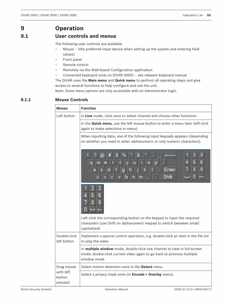
DIVAR 2000 / DIVAR 3000 / DIVAR 5000 Operation | en 59
Bosch Security Systems Operation Manual 2018.10 | V2.0 | AM18-Q0717
9 Operation9.1 User controls and menus
The following user controls are available:– Mouse – (the preferred input device when setting up the system and entering field
values)– Front panel– Remote control– Remotely via the Web-based Configuration application– Connected keyboard (only on DIVAR 5000) – see relevant keyboard manualThe DIVAR uses the Main menu and Quick menu to perform all operating steps and giveaccess to several functions to help configure and use the unit.Note: Some menu options are only accessible with an Administrator login.
9.1.1 Mouse Controls
Mouse Function
Left button In Live mode, click once to select channel and choose other functions
In the Quick menu, use the left mouse button to enter a menu item (left-clickagain to make selections in menu)
When inputting data, one of the following input keypads appears (dependingon whether you need to enter alphanumeric or only numeric characters):
Left click the corresponding button on the keypad to input the requiredcharacters (use Shift on alphanumeric keypad to switch between small/capitalized)
Double-clickleft button
Implement a special control operation, e.g. double-click an item in the file listto play the video
In multiple window mode, double-click one channel to view in full-screenmode; double-click current video again to go back to previous multiplewindow mode
Drag mousewith leftbuttonpressed
Select motion detection zone in the Detect menu
Select a privacy mask zone (in Encode > Overlay menu).
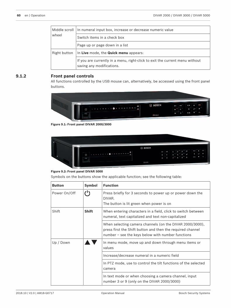
60 en | Operation DIVAR 2000 / DIVAR 3000 / DIVAR 5000
2018.10 | V2.0 | AM18-Q0717 Operation Manual Bosch Security Systems
Middle scrollwheel
In numeral input box, increase or decrease numeric value
Switch items in a check box
Page up or page down in a list
Right button In Live mode, the Quick menu appears:
If you are currently in a menu, right-click to exit the current menu withoutsaving any modifications.
9.1.2 Front panel controlsAll functions controlled by the USB mouse can, alternatively, be accessed using the front panelbuttons.
Figure 9.1: Front panel DIVAR 2000/3000
Figure 9.2: Front panel DIVAR 5000
Symbols on the buttons show the applicable function; see the following table:
Button Symbol Function
Power On/Off Press briefly for 3 seconds to power up or power down theDIVAR.The button is lit green when power is on
Shift Shift When entering characters in a field, click to switch betweennumeral, text capitalized and text non-capitalized
When selecting camera channels (on the DIVAR 2000/3000),press first the Shift button and then the required channelnumber – see the keys below with number functions
Up / Down In menu mode, move up and down through menu items orvalues
Increase/decrease numeral in a numeric field
In PTZ mode, use to control the tilt functions of the selectedcamera
In text mode or when choosing a camera channel, inputnumber 3 or 9 (only on the DIVAR 2000/3000)
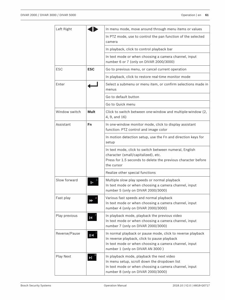
DIVAR 2000 / DIVAR 3000 / DIVAR 5000 Operation | en 61
Bosch Security Systems Operation Manual 2018.10 | V2.0 | AM18-Q0717
Left Right In menu mode, move around through menu items or values
In PTZ mode, use to control the pan function of the selectedcamera
In playback, click to control playback bar
In text mode or when choosing a camera channel, inputnumber 6 or 7 (only on DIVAR 2000/3000)
ESC ESC Go to previous menu, or cancel current operation
In playback, click to restore real-time monitor mode
Enter Select a submenu or menu item, or confirm selections made inmenus
Go to default button
Go to Quick menu
Window switch Mult Click to switch between one-window and multiple-window (2,4, 9, and 16)
Assistant Fn In one-window monitor mode, click to display assistantfunction: PTZ control and image color
In motion detection setup, use the Fn and direction keys forsetup
In text mode, click to switch between numeral, Englishcharacter (small/capitalized), etc.Press for 1.5 seconds to delete the previous character beforethe cursor
Realize other special functions
Slow forward Multiple slow play speeds or normal playbackIn text mode or when choosing a camera channel, inputnumber 5 (only on DIVAR 2000/3000)
Fast play Various fast speeds and normal playbackIn text mode or when choosing a camera channel, inputnumber 4 (only on DIVAR 2000/3000)
Play previous In playback mode, playback the previous videoIn text mode or when choosing a camera channel, inputnumber 7 (only on DIVAR 2000/3000)
Reverse/Pause In normal playback or pause mode, click to reverse playbackIn reverse playback, click to pause playbackIn text mode or when choosing a camera channel, inputnumber 1 (only on DIVAR AN 3000 )
Play Next In playback mode, playback the next videoIn menu setup, scroll down the dropdown listIn text mode or when choosing a camera channel, inputnumber 8 (only on DIVAR 2000/3000)
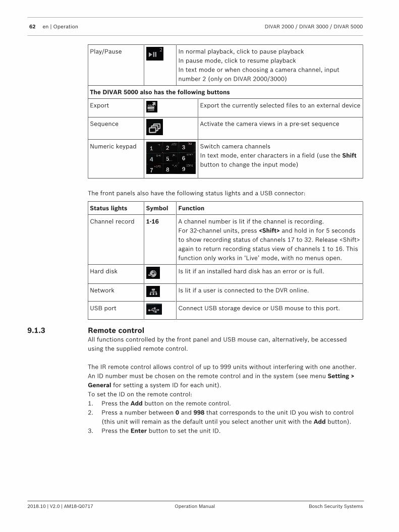
62 en | Operation DIVAR 2000 / DIVAR 3000 / DIVAR 5000
2018.10 | V2.0 | AM18-Q0717 Operation Manual Bosch Security Systems
Play/Pause In normal playback, click to pause playbackIn pause mode, click to resume playbackIn text mode or when choosing a camera channel, inputnumber 2 (only on DIVAR 2000/3000)
The DIVAR 5000 also has the following buttons
Export Export the currently selected files to an external device
Sequence Activate the camera views in a pre-set sequence
Numeric keypad Switch camera channelsIn text mode, enter characters in a field (use the Shiftbutton to change the input mode)
The front panels also have the following status lights and a USB connector:
Status lights Symbol Function
Channel record 1-16 A channel number is lit if the channel is recording. For 32-channel units, press <Shift> and hold in for 5 secondsto show recording status of channels 17 to 32. Release <Shift>again to return recording status view of channels 1 to 16. Thisfunction only works in ‘Live’ mode, with no menus open.
Hard disk Is lit if an installed hard disk has an error or is full.
Network Is lit if a user is connected to the DVR online.
USB port Connect USB storage device or USB mouse to this port.
9.1.3 Remote controlAll functions controlled by the front panel and USB mouse can, alternatively, be accessedusing the supplied remote control.
The IR remote control allows control of up to 999 units without interfering with one another.An ID number must be chosen on the remote control and in the system (see menu Setting >General for setting a system ID for each unit).To set the ID on the remote control:1. Press the Add button on the remote control.2. Press a number between 0 and 998 that corresponds to the unit ID you wish to control
(this unit will remain as the default until you select another unit with the Add button).3. Press the Enter button to set the unit ID.
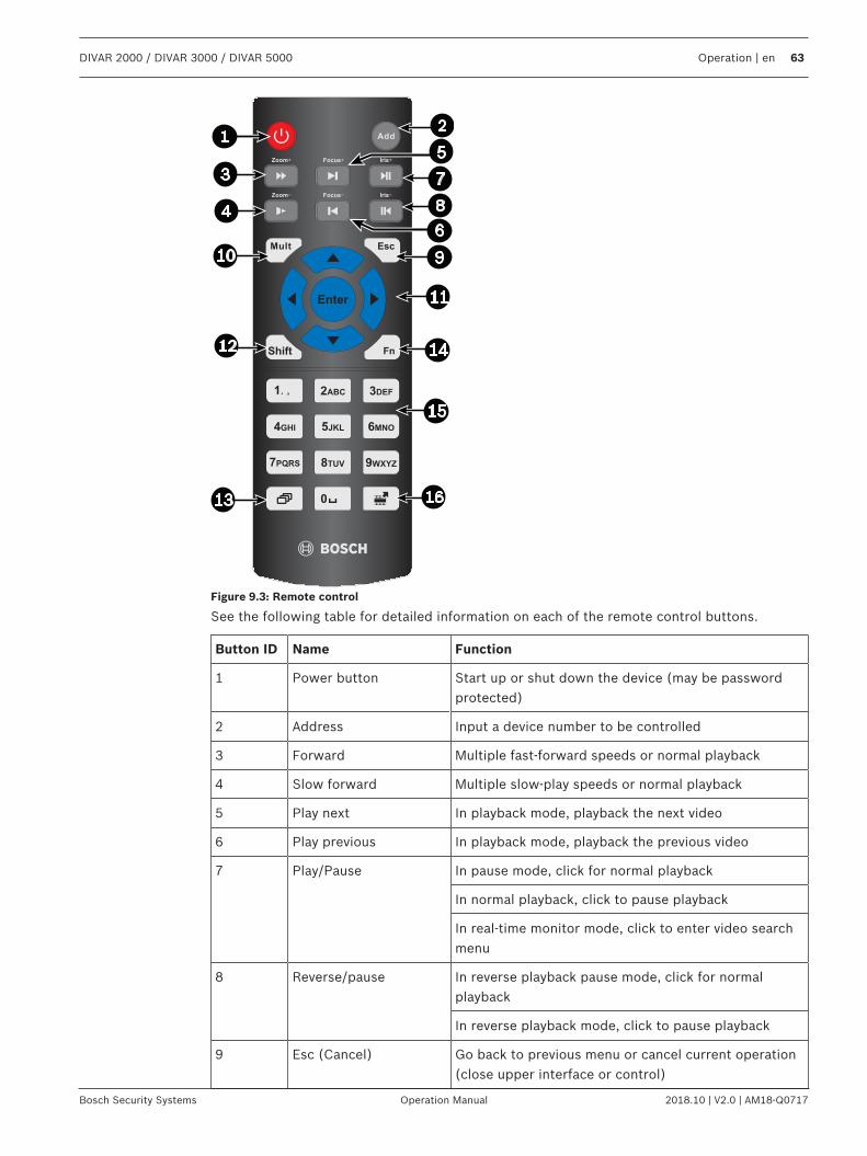
DIVAR 2000 / DIVAR 3000 / DIVAR 5000 Operation | en 63
Bosch Security Systems Operation Manual 2018.10 | V2.0 | AM18-Q0717
Figure 9.3: Remote control
See the following table for detailed information on each of the remote control buttons.
Button ID Name Function
1 Power button Start up or shut down the device (may be passwordprotected)
2 Address Input a device number to be controlled
3 Forward Multiple fast-forward speeds or normal playback
4 Slow forward Multiple slow-play speeds or normal playback
5 Play next In playback mode, playback the next video
6 Play previous In playback mode, playback the previous video
7 Play/Pause In pause mode, click for normal playback
In normal playback, click to pause playback
In real-time monitor mode, click to enter video searchmenu
8 Reverse/pause In reverse playback pause mode, click for normalplayback
In reverse playback mode, click to pause playback
9 Esc (Cancel) Go back to previous menu or cancel current operation(close upper interface or control)
64 en | Operation DIVAR 2000 / DIVAR 3000 / DIVAR 5000
2018.10 | V2.0 | AM18-Q0717 Operation Manual Bosch Security Systems
10 Mult Switch between multiple-windows and single-window
11 In menu mode, move up and down through menu itemsor valuesIncrease/decrease numeral in a numeric fieldIn PTZ mode, use to control the tilt functions of theselected camera
In menu mode, move around through menu items orvaluesIn PTZ mode, use to control the pan function of theselected cameraIn playback, click to control playback bar
Enter Go to defaultGo to the selected menu
12 Shift Switch the input of characters between numbers, textcapitalized and text non-capitalized
13 Sequence Activate the camera views in a pre-set sequence
14 Assistant (Fn) key In 1-ch monitor mode: pop up assistant function:PTZcontrol and image color
In PTZ control mode, switch the PTZ control menu
In motion detection mode, use together with thedirection keys to complete setup
15 0-9 number key Switch camera channels (for channels 10 to 16, press1 then second number within
In text mode, enter characters in a field (use the Shiftbutton to change the input mode)
16 Export Export the currently selected files to an external device
DIVAR 2000 / DIVAR 3000 / DIVAR 5000 Operation | en 65
Bosch Security Systems Operation Manual 2018.10 | V2.0 | AM18-Q0717
9.1.4 Quick menu
When in live viewing mode, right-click the mouse for the Quick menu. Options here are:View 1, 4, 8, 9, 16, 32 - choose here the number of view windows shown on Monitor A (one-window, four-windows, nine-windows, 16-windows or 32-windows). For each window view,select also which channels (cameras) to displayView monitor B (optional) - a popup appears where you can assign the view windows andchannels for images to be shown on monitor BAssign camera - assign the 1st or 2nd stream of a camera to the selected view windowSave View - save the current layout of view windows in a new view or overwrite an existingviewPan/Tilt/Zoom - only possible if you have a PTZ camera attached and configuredSearch/Play - search for records, and play/export themEvent search - search for events (alarms), and play/export themSnapshot - make a snapshot of the current live camera images:– A disclaimer screen may initially appear when you select Snapshot (click <Accept> to
continue).– Choose to export the snapshot to an email address, a USB memory device, and/or a DVD.Sequence on - activate a camera tour sequence on Monitor A (to disable the sequence, accessQuick Menu again and select ‘Sequence off’)Alarm output - access the alarm output screen to configure the alarm output relaysLogout user - logout the current user (a popup appears to confirm logout)Main menu - for settings and user modes
Notice!The Pan/Tilt/Zoom setting applies for the currently selected channel. If you are in multiple-window mode, the system automatically switches to the corresponding channel.
9.1.5 Main menuAccess the Main menu as follows:– Use the Enter key and the direction buttons on the front panel or the remote control– Right-click the mouse for the quick menu and select ‘Main menu’
Here you can select the following sub-menus:– Playback to play recordings– Event search to search for events/alarms over a set period (all events can be previewed,
played and exported as required)– Export to export your recorded files to a memory device– Setting for system configuration– Info for relevant system status information– Shutdown - shutdown or restart your system, plus logout
9.2 Live screenThe units have a maximum possibility for three monitor outputs (depending on availableconnectors on the rear of the unit):– two for monitor A– one for monitor B.
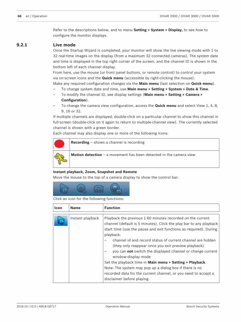
66 en | Operation DIVAR 2000 / DIVAR 3000 / DIVAR 5000
2018.10 | V2.0 | AM18-Q0717 Operation Manual Bosch Security Systems
Refer to the descriptions below, and to menu Setting > System > Display, to see how toconfigure the monitor displays.
9.2.1 Live modeOnce the Startup Wizard is completed, your monitor will show the live viewing mode with 1 to32 real-time images on the display (from a maximum 32 connected cameras). The system dateand time is displayed in the top right corner of the screen, and the channel ID is shown in thebottom left of each channel display.From here, use the mouse (or front panel buttons, or remote control) to control your systemvia on-screen icons and the Quick menu (accessible by right-clicking the mouse).Make any required configuration changes via the Main menu (last selection on Quick menu).– To change system date and time, use Main menu > Setting > System > Date & Time.– To modify the channel ID, see display settings (Main menu > Setting > Camera >
Configuration).– To change the camera view configuration, access the Quick menu and select View 1, 4, 8,
9, 16 or 32.If multiple channels are displayed, double-click on a particular channel to show this channel infull-screen (double-click on it again to return to multiple-channel view). The currently selectedchannel is shown with a green border.Each channel may also display one or more of the following icons:
Recording – shows a channel is recording
Motion detection – a movement has been detected in the camera view
Instant playback, Zoom, Snapshot and RemoteMove the mouse to the top of a camera display to show the control bar:
Click an icon for the following functions:
Icon Name Function
Instant playback Playback the previous 1-60 minutes recorded on the currentchannel (default is 5 minutes). Click the play bar to any playbackstart time (use the pause and exit functions as required). Duringplayback:– channel id and record status of current channel are hidden
(they only reappear once you exit preview playback)– you can not switch the displayed channel or change current
window-display modeSet the playback time in Main menu > Setting > Playback.Note: The system may pop up a dialog box if there is norecorded data for the current channel, or you need to accept adisclaimer before playing.
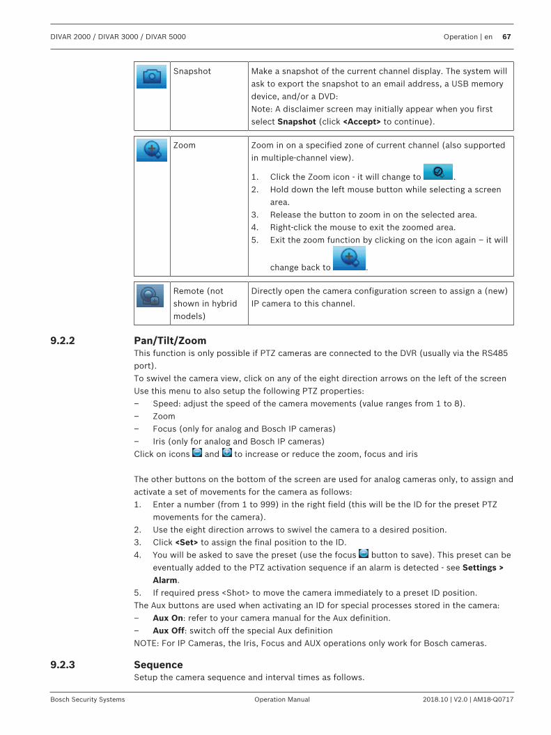
DIVAR 2000 / DIVAR 3000 / DIVAR 5000 Operation | en 67
Bosch Security Systems Operation Manual 2018.10 | V2.0 | AM18-Q0717
Snapshot Make a snapshot of the current channel display. The system willask to export the snapshot to an email address, a USB memorydevice, and/or a DVD:Note: A disclaimer screen may initially appear when you firstselect Snapshot (click <Accept> to continue).
Zoom Zoom in on a specified zone of current channel (also supportedin multiple-channel view).
1. Click the Zoom icon - it will change to .2. Hold down the left mouse button while selecting a screen
area.3. Release the button to zoom in on the selected area.4. Right-click the mouse to exit the zoomed area.5. Exit the zoom function by clicking on the icon again – it will
change back to .
Remote (notshown in hybridmodels)
Directly open the camera configuration screen to assign a (new)IP camera to this channel.
9.2.2 Pan/Tilt/ZoomThis function is only possible if PTZ cameras are connected to the DVR (usually via the RS485port).To swivel the camera view, click on any of the eight direction arrows on the left of the screenUse this menu to also setup the following PTZ properties:– Speed: adjust the speed of the camera movements (value ranges from 1 to 8).– Zoom– Focus (only for analog and Bosch IP cameras)– Iris (only for analog and Bosch IP cameras)Click on icons and to increase or reduce the zoom, focus and iris
The other buttons on the bottom of the screen are used for analog cameras only, to assign andactivate a set of movements for the camera as follows:1. Enter a number (from 1 to 999) in the right field (this will be the ID for the preset PTZ
movements for the camera).2. Use the eight direction arrows to swivel the camera to a desired position.3. Click <Set> to assign the final position to the ID.4. You will be asked to save the preset (use the focus button to save). This preset can be
eventually added to the PTZ activation sequence if an alarm is detected - see Settings >Alarm.
5. If required press <Shot> to move the camera immediately to a preset ID position.The Aux buttons are used when activating an ID for special processes stored in the camera:– Aux On: refer to your camera manual for the Aux definition.– Aux Off: switch off the special Aux definitionNOTE: For IP Cameras, the Iris, Focus and AUX operations only work for Bosch cameras.
9.2.3 SequenceSetup the camera sequence and interval times as follows.
68 en | Operation DIVAR 2000 / DIVAR 3000 / DIVAR 5000
2018.10 | V2.0 | AM18-Q0717 Operation Manual Bosch Security Systems
Activate sequence on monitor A (or B)1. To view a sequence of live camera pictures from several cameras:
– Right-click the mouse to access the Quick menu– Choose Sequence on
2. Check that a sequence of camera pictures appears,3. To stop sequencing, right-click the mouse to access the Quick menu, and choose
Sequence off
NOTE: The sequence can be paused by clicking inside the sequence icon. This allows the userto switch between cameo’s and view windows and control the PTZ of cameras. To resume thesequence mode, simply select the icon again. This applies to sequence modes started with thenormal sequence on/off option as well as for sequence mode started by alarm event display.
9.2.4 Monitor AMonitor A shows live pictures of connected cameras in full-screen or multiscreen, plus statusmessages and alarm events (e.g. motion and video loss warnings). When multiple eventsoccur, camera pictures can also be sequenced on monitor A to follow the events.The search/play function and all user menus are also activated on this monitor.
9.2.5 Monitor B (only for DIVAR 5000 models)Monitor B displays live pictures in full-screen or multiscreen (up to 16 channel can be shownat one time, with a choice of which channels to show e.g. channels 1 to 16, or channels 17 to32).If an alarm/detect event is signaled, the camera picture with the event can be displayed onmonitor B. When multiple events occur, camera pictures can also be sequenced on monitor Bto follow the events.
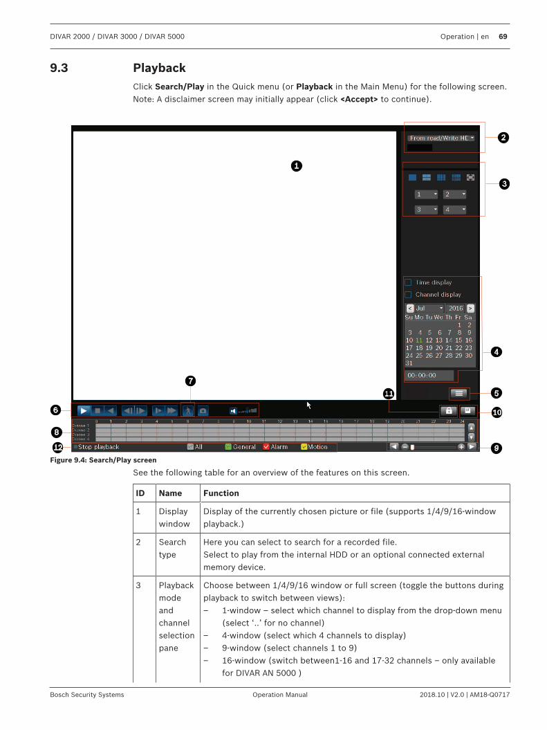
DIVAR 2000 / DIVAR 3000 / DIVAR 5000 Operation | en 69
Bosch Security Systems Operation Manual 2018.10 | V2.0 | AM18-Q0717
9.3 PlaybackClick Search/Play in the Quick menu (or Playback in the Main Menu) for the following screen.Note: A disclaimer screen may initially appear (click <Accept> to continue).
Figure 9.4: Search/Play screen
See the following table for an overview of the features on this screen.
ID Name Function
1 Displaywindow
Display of the currently chosen picture or file (supports 1/4/9/16-windowplayback.)
2 Searchtype
Here you can select to search for a recorded file.Select to play from the internal HDD or an optional connected externalmemory device.
3 Playbackmodeandchannelselectionpane
Choose between 1/4/9/16 window or full screen (toggle the buttons duringplayback to switch between views):– 1-window – select which channel to display from the drop-down menu
(select ‘..’ for no channel)– 4-window (select which 4 channels to display)– 9-window (select channels 1 to 9)– 16-window (switch between1-16 and 17-32 channels – only available
for DIVAR AN 5000 )
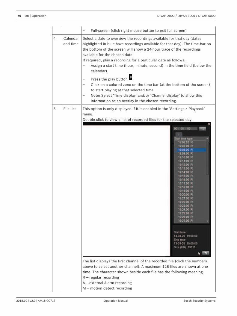
70 en | Operation DIVAR 2000 / DIVAR 3000 / DIVAR 5000
2018.10 | V2.0 | AM18-Q0717 Operation Manual Bosch Security Systems
– Full-screen (click right mouse button to exit full screen)
4 Calendarand time
Select a date to overview the recordings available for that day (dateshighlighted in blue have recordings available for that day). The time bar onthe bottom of the screen will show a 24-hour trace of the recordingsavailable for the chosen date.If required, play a recording for a particular date as follows:– Assign a start time (hour, minute, second) in the time field (below the
calendar)
– Press the play button – Click on a colored zone on the time bar (at the bottom of the screen)
to start playing at that selected time– Note: Select ‘Time display’ and/or ‘Channel display’ to show this
information as an overlay in the chosen recording.
5 File list This option is only displayed if it is enabled in the ‘Settings > Playback’menu.Double click to view a list of recorded files for the selected day.
The list displays the first channel of the recorded file (click the numbersabove to select another channel). A maximum 128 files are shown at onetime. The character shown beside each file has the following meaning:R — regular recordingA — external Alarm recordingM — motion detect recording
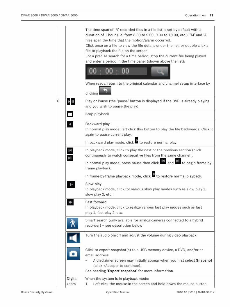
DIVAR 2000 / DIVAR 3000 / DIVAR 5000 Operation | en 71
Bosch Security Systems Operation Manual 2018.10 | V2.0 | AM18-Q0717
The time span of ‘R’ recorded files in a file list is set by default with aduration of 1 hour (i.e. from 8:00 to 9:00, 9:00 to 10:00, etc.). ‘M’ and ‘A’files span the time that the motion/alarm occurred.Click once on a file to view the file details under the list, or double click afile to playback the file on the screen.For a precise search for a time period, stop the current file being playedand enter a period in the time panel (shown above the list):
When ready, return to the original calendar and channel setup interface by
clicking
6
Play or Pause (the ‘pause’ button is displayed if the DVR is already playingand you wish to pause the play)
Stop playback
Backward playIn normal play mode, left click this button to play the file backwards. Click itagain to pause current play.
In backward play mode, click to restore normal play.
In playback mode, click to play the next or the previous section (clickcontinuously to watch consecutive files from the same channel).
In normal play mode, press pause then click and to begin frame-by-frame playback.
In frame-by-frame playback mode, click to restore normal playback.
Slow playIn playback mode, click for various slow play modes such as slow play 1,slow play 2, etc.
Fast forwardIn playback mode, click to realize various fast play modes such as fastplay 1, fast play 2, etc.
Smart search (only available for analog cameras connected to a hybridrecorder) – see description below
Turn the audio on/off and adjust the volume during video playback
Click to export snapshot(s) to a USB memory device, a DVD, and/or anemail address.– A disclaimer screen may initially appear when you first select Snapshot
(click <Accept> to continue).See heading ‘Export snapshot’ for more information.
Digitalzoom
When the system is in playback mode:1. Left-click the mouse in the screen and hold down the mouse button.
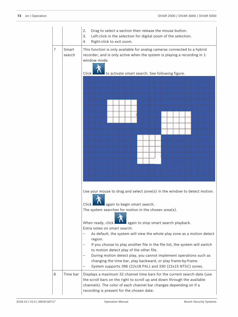
72 en | Operation DIVAR 2000 / DIVAR 3000 / DIVAR 5000
2018.10 | V2.0 | AM18-Q0717 Operation Manual Bosch Security Systems
2. Drag to select a section then release the mouse button.3. Left-click in the selection for digital zoom of the selection.4. Right-click to exit zoom.
7 Smartsearch
This function is only available for analog cameras connected to a hybridrecorder, and is only active when the system is playing a recording in 1-window mode.
Click to activate smart search. See following figure.
Use your mouse to drag and select zone(s) in the window to detect motion.
Click again to begin smart search.The system searches for motion in the chosen area(s).
When ready, click again to stop smart search playback.Extra notes on smart search:– As default, the system will view the whole play zone as a motion detect
region.– If you choose to play another file in the file list, the system will switch
to motion detect play of the other file.– During motion detect play, you cannot implement operations such as
changing the time bar, play backward, or play frame-by-frame.– System supports 396 (22x18 PAL) and 330 (22x15 NTSC) zones.
8 Time bar Displays a maximum 32 channel time bars for the current search date (usethe scroll bars on the right to scroll up and down through the availablechannels). The color of each channel bar changes depending on if arecording is present for the chosen date:
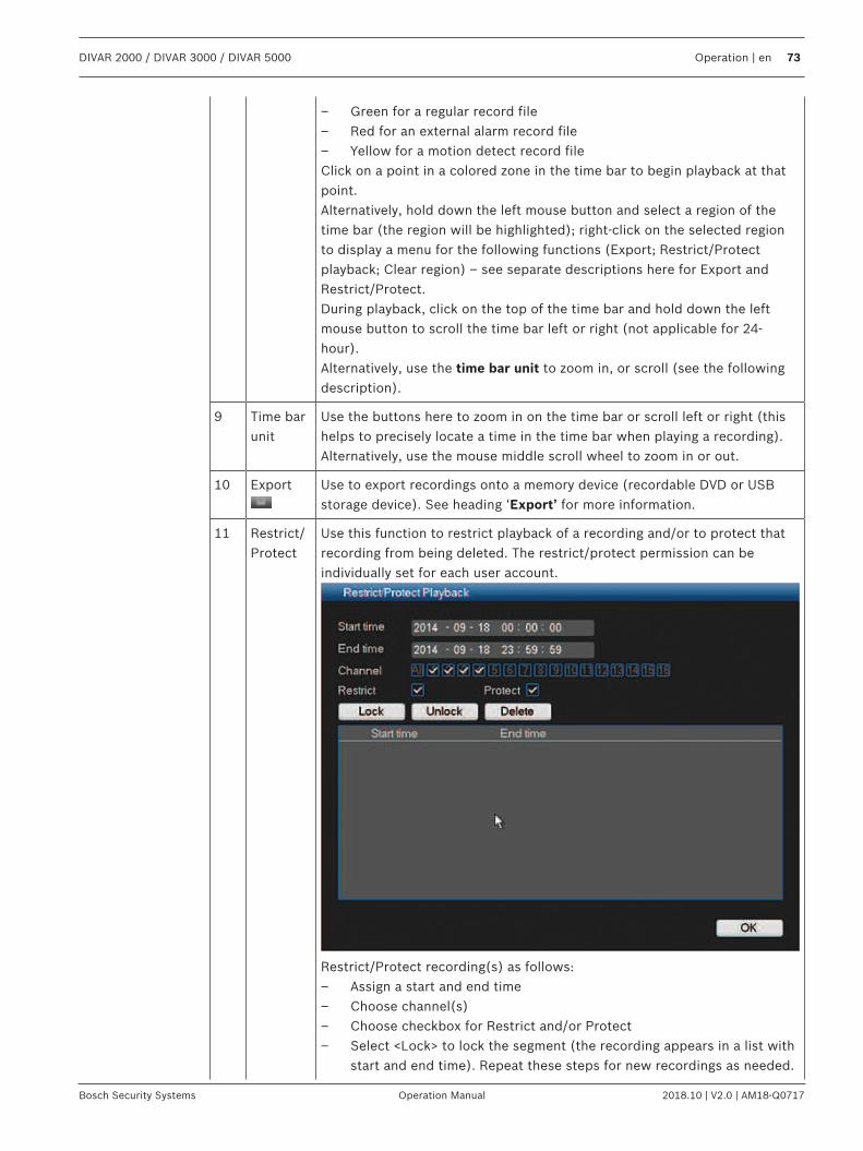
DIVAR 2000 / DIVAR 3000 / DIVAR 5000 Operation | en 73
Bosch Security Systems Operation Manual 2018.10 | V2.0 | AM18-Q0717
– Green for a regular record file– Red for an external alarm record file– Yellow for a motion detect record fileClick on a point in a colored zone in the time bar to begin playback at thatpoint.Alternatively, hold down the left mouse button and select a region of thetime bar (the region will be highlighted); right-click on the selected regionto display a menu for the following functions (Export; Restrict/Protectplayback; Clear region) – see separate descriptions here for Export andRestrict/Protect.During playback, click on the top of the time bar and hold down the leftmouse button to scroll the time bar left or right (not applicable for 24-hour).Alternatively, use the time bar unit to zoom in, or scroll (see the followingdescription).
9 Time barunit
Use the buttons here to zoom in on the time bar or scroll left or right (thishelps to precisely locate a time in the time bar when playing a recording).Alternatively, use the mouse middle scroll wheel to zoom in or out.
10 Export Use to export recordings onto a memory device (recordable DVD or USBstorage device). See heading ‘Export’ for more information.
11 Restrict/Protect
Use this function to restrict playback of a recording and/or to protect thatrecording from being deleted. The restrict/protect permission can beindividually set for each user account.
Restrict/Protect recording(s) as follows:– Assign a start and end time– Choose channel(s)– Choose checkbox for Restrict and/or Protect– Select <Lock> to lock the segment (the recording appears in a list with
start and end time). Repeat these steps for new recordings as needed.

74 en | Operation DIVAR 2000 / DIVAR 3000 / DIVAR 5000
2018.10 | V2.0 | AM18-Q0717 Operation Manual Bosch Security Systems
– If required, unlock a recording by selecting its checkbox and select<Unlock>. Delete a recording permanently with <Delete>
– Select <OK> to save the settings (depending on user access, allrestricted/protected recordings will show a blank screen with a locklogo when playing)
Important: When entering a start and end time for Restrict/Protectplayback, be aware that the selected time may include a portion of arecorded file. In this case the complete file will be Restricted/Protected. Forexample, if you set a start time of 9:30 and an end time of 10:30 then boththe recorded files 9:00 to 10:00 and 10:00 to 11:00 will be selected forrestrict/protect because they both include portions of the selected timespan. The same principle applies if you Delete a time period from 9:30 to10:30 then both the files 9:00 to 10:00 and 10:00 to 11:00 will be deleted.
12 Recordtype
Only displayed if ‘Show timeline selection’ is selected in Settings > System> Playback menu (selected by default)..This status line shows the current play mode (or Stop). The checked boxes show the recording type (All, General, Motion, Alarm).
DIVAR 2000 / DIVAR 3000 / DIVAR 5000 Operation | en 75
Bosch Security Systems Operation Manual 2018.10 | V2.0 | AM18-Q0717
9.3.1 ExportAccess the Export menu from the main menu or Search/Play screen (or by pressing the Exportkey on the Front Panel or on the remote control). Use this menu to write segments ofrecorded video to a USB storage device or recordable DVD.1. Choose from the Selected Device pull-down list to export recording(s) to either a USB
memory stick or CD/DVD. If required, <Refresh> the device selection, or <Format> theselected memory device.
2. Choose the save location on the memory device (<Browse> if necessary).3. Select the Type of file to export (All, Alarm, MD, Normal).4. Select the File format (DAV or ASF).5. Enter a Start time and End time for the video segments (files) to archive.6. Select the Channel to archive (All for all channels).7. Click <Add> to add the file to the export list.8. If required, repeat steps 3 to 7 for more recordings. (Remove a selected recording by
selecting its check box and pressing <Remove>.)The total size of the selected recordings (and available space on the memory device) areshown.
9. Click <Start> to export the selected recording(s).If the total size of the selected recordings is more than the free space on the memorydevice, then only the first recordings that fit are exported.
9.3.2 Export snapshotSelect the checkboxes to export snapshots to an email address, USB memory stick and/orDVD.If required, enter an email address or choose a specific DVD or USB stick (use <Configure> todefine a location on the USB).Use <Refresh> to refresh the selection if you insert a new USB stick or DVD.
Notice!Exporting snapshots to a DVD will first format the DVD (deleting all files currently on theDVD).
9.4 InfoRefer to the following sections for a description of these System information menus.
9.4.1 System AlarmView here the alarm status of your system:– System alarms (No disk, Disk error, No space on disk, Network lost, IP conflict,
Temperature too high, Other)– Event alarms (Motion detection, Video loss, Camera input, NVR input). Use the scroll
arrows to view all camera events.
9.4.2 System HealthView here the health status of your system:– Temperature– CPU load– Memory usage
76 en | Operation DIVAR 2000 / DIVAR 3000 / DIVAR 5000
2018.10 | V2.0 | AM18-Q0717 Operation Manual Bosch Security Systems
– Fan speed (only for DIVAR 3000 models) - values shown are Current, Average, Highest,Lowest)
9.4.3 System VersionView here the status of your installed system:– hardware features (device, channels, alarms in/out)– software features
– system version of your currently installed firmware– build date of the firmware– web id– serial number
Notice!Bosch strongly recommends upgrading to the latest firmware for the best possiblefunctionality, compatibility, performance and security.Check http://downloadstore.boschsecurity.com/ regularly to see if there is a new firmwareversion available.
9.4.4 Network Online usersManage here the online users:– Disconnect a user by selecting the user and press <Disconnect>.– Block a user for a max disconnection time:
– Select the user– Click Block time (default is 60 seconds) and select <Block >
The system displays a list of the blocked users, and refreshes every five seconds to detect anynewly added or deleted users. To unblock a user, select the user and choose <Unblock>.
9.4.5 PoE usageThis info page shows a list of all cameras connected to the PoE slots, and the total amount ofpower they are using. Use the Block checkbox for a camera to prevent the camera drawing aPoE supply from that slot.
9.4.6 Network LoadSee here a real time graphical display of the current load on the network for send and receivetraffic. There are two network connections and the load can be seen for each network byselecting the relevant network interface.
9.4.7 Network TestChoose here to do a network test as follows:1. Enter a Destination IP address.2. Click <Test>.3. Check the test result in the Test result field.
Or choose to do a Network sniffer packet export as follows:1. Enter a Device name (click <Refresh> if the device is not shown).2. Enter an Address (click <Browse> to search for the correct path).3. Select LAN.
4. When the correct sniffer packet is shown, click to start the export.
DIVAR 2000 / DIVAR 3000 / DIVAR 5000 Operation | en 77
Bosch Security Systems Operation Manual 2018.10 | V2.0 | AM18-Q0717
9.4.8 HDD GeneralThis screen provides information on the current status of each HDD. After a system start, thesystem will first check for any HDD error.Earliest recording: shows the date and time of the oldest recording still available on HDD.Latest recording: shows the date and time of the latest recording on HDD.Recording status: shows if HDD can record or not.Raid status: shows if HDD is used in a Raid array. Using RAID severely reduces systemperformance (to maintain fluent playback, it is recommended to limit the number of playbackchannels (e.g. 1x or 4x playback).Total protected size: shows the total size of all protected recordings stored on the HDD (youcan protect a recording using the Protect Playback function available on the Search/Playscreen).
The bottom half of the screen lists each HDD type, total size, and the free space remaining onthe disk. Use the Health menu for more (Smart) information.
9.4.9 HDD HealthScanStart a scan here to view the current status of all sectors on the HDD(s) installed in your unit.A graphical representation of the HDD segments is shown, plus a readout of the health statusof each HDD.Start the scan as follows:1. Choose Quick or Full detect.2. Choose the HDD to be scanned.3. Press <Start>.
ReportAfter a scan is run on your HDD, use the Report tab to display a quick overview of the result.Any detected errors will be shown in the Error column (O means current HDD is normal; Xmeans there is a disk error; – means there is no HDD; ? means disk is damaged).
Notice!If an error (X) is shownCheck the hard disk time and system time are the same (if necessary, modify system time inSetting > General, and reboot the system). If the error persists, check the S.M.A.R.T.information (see below) and, if necessary, format the HDD and reboot the system.
If more detailed information is needed, select the ‘report icon’ under the View column (hereyou can also select the S.M.A.R.T. tab - see below).To make a backup of the report:1. Insert a USB stick into an empty slot on the unit.2. Choose <Backup> to export the report to the USB stick.
S.M.A.R.T.Choose here to display all of the Self-Monitoring, Analysis and Reporting Technologyinformation that is automatically collected by the monitoring system included in hard diskdrives (HDDs) and solid-state drives (SSDs). This system reports on various indicators of drivereliability, with the intent of enabling the anticipation of hardware failures.
78 en | Operation DIVAR 2000 / DIVAR 3000 / DIVAR 5000
2018.10 | V2.0 | AM18-Q0717 Operation Manual Bosch Security Systems
9.4.10 LogView here (and export) the log files containing the following system events:– All– System– Config– Storage– Event– record– Account– Clear– Playback– ConnectionThe system can display a maximum 100 logs per page and a maximum 115 pages of log files(displayed in order of newest to oldest). Use the scroll bar or Page up/down or Previous/Next page to scroll through the events if there are more than ten events.
How to use log display1. Select which system events to show from the drop-down menu in the Type field (choose
All to display all events).2. Enter a Start time and End time in the relevant field3. Click <Search> to view the log for the event type.4. Use <Play> and <Preview> icons to view events.5. If required, double-click on a log entry (or select the entry and click <Details>) to view
more information on the event.6. To save the log file to a USB stick, click <Backup> and enter the required fields in the Log
backup dialog box.7. To delete all the log files, click <Clear> and confirm the delete action.
9.5 ExportAssign here a schedule for an automatic export (backup) of a recording to an FTP (Filetransfer Protocol), SMB (Server Message Block) server, or to an eSata disk (only available forthe DIVAR 5000)– Selected device: choose which device to save the backup– Path: choose where to save the backup– Type: Select the type of video for back-up (choose between alarm recording, motion
recording, alarm and motion recording, normal recording, or all)– File format: DAV (default) or ASF– Start time: Assign the date and start time of the backup (because a backup can drain
system performance, always schedule a start time during a quiet period where featuressuch as local playback/export are not required)
– End time: Assign the end date and time of the backup– Channel: Assign the channel(s) to be backed up (default is All)Press <Add> to add this export to the schedule list below; add more scheduled backups asrequired (to remove a scheduled backup, select it on the list and press <Remove>).Do not forget to press <Start> to start the backup.The bottom of the screen shows the progress of the backup.
DIVAR 2000 / DIVAR 3000 / DIVAR 5000 Operation | en 79
Bosch Security Systems Operation Manual 2018.10 | V2.0 | AM18-Q0717
9.6 Event searchClick Event search in the Quick menu (or Event search in the Main Menu) to activate thescreen for searching for events.Options in this screen are:– Type: Choose from All (default), Motion or Alarm– Channel: Choose All or specific channels– Start time: Choose start date and time for search– End time: Choose end date and time for searchPress <Search> to start the event search. If required, use <Go to> to access a particular pagein the list of events. Double-click an event to display more information; press the green arrowto playback the event.To export event file(s), use <Browse> to assign an export device, select the required files,then press <Export> (the progress of the export is shown on the status bar).
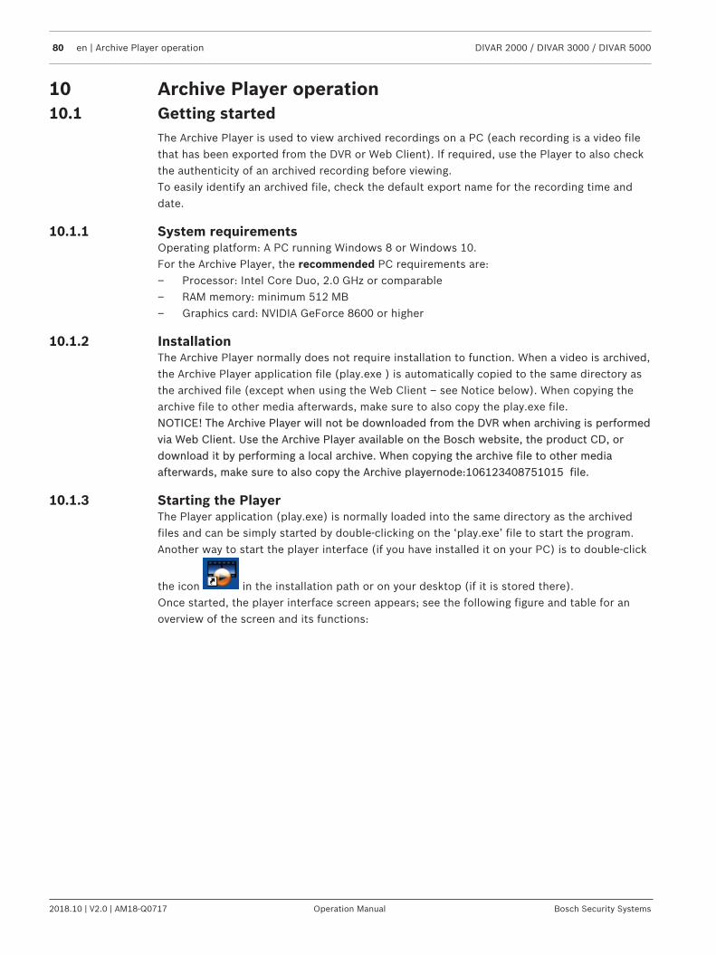
80 en | Archive Player operation DIVAR 2000 / DIVAR 3000 / DIVAR 5000
2018.10 | V2.0 | AM18-Q0717 Operation Manual Bosch Security Systems
10 Archive Player operation10.1 Getting started
The Archive Player is used to view archived recordings on a PC (each recording is a video filethat has been exported from the DVR or Web Client). If required, use the Player to also checkthe authenticity of an archived recording before viewing.To easily identify an archived file, check the default export name for the recording time anddate.
10.1.1 System requirementsOperating platform: A PC running Windows 8 or Windows 10.For the Archive Player, the recommended PC requirements are:– Processor: Intel Core Duo, 2.0 GHz or comparable– RAM memory: minimum 512 MB– Graphics card: NVIDIA GeForce 8600 or higher
10.1.2 InstallationThe Archive Player normally does not require installation to function. When a video is archived,the Archive Player application file (play.exe ) is automatically copied to the same directory asthe archived file (except when using the Web Client – see Notice below). When copying thearchive file to other media afterwards, make sure to also copy the play.exe file.NOTICE! The Archive Player will not be downloaded from the DVR when archiving is performedvia Web Client. Use the Archive Player available on the Bosch website, the product CD, ordownload it by performing a local archive. When copying the archive file to other mediaafterwards, make sure to also copy the Archive playernode:106123408751015 file.
10.1.3 Starting the PlayerThe Player application (play.exe) is normally loaded into the same directory as the archivedfiles and can be simply started by double-clicking on the ‘play.exe’ file to start the program.Another way to start the player interface (if you have installed it on your PC) is to double-click
the icon in the installation path or on your desktop (if it is stored there).Once started, the player interface screen appears; see the following figure and table for anoverview of the screen and its functions:
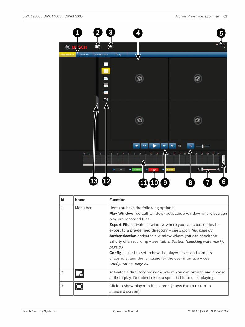
DIVAR 2000 / DIVAR 3000 / DIVAR 5000 Archive Player operation | en 81
Bosch Security Systems Operation Manual 2018.10 | V2.0 | AM18-Q0717
Id Name Function
1 Menu bar Here you have the following options:Play Window (default window) activates a window where you canplay pre-recorded files.Export File activates a window where you can choose files toexport to a pre-defined directory – see Export file, page 83Authentication activates a window where you can check thevalidity of a recording – see Authentication (checking watermark),page 83Config is used to setup how the player saves and formatssnapshots, and the language for the user interface – seeConfiguration, page 84
2 Activates a directory overview where you can browse and choosea file to play. Double-click on a specific file to start playing.
3 Click to show player in full screen (press Esc to return tostandard screen)
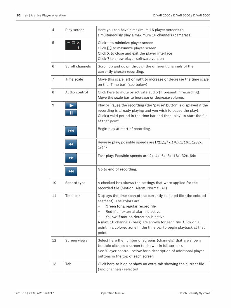
82 en | Archive Player operation DIVAR 2000 / DIVAR 3000 / DIVAR 5000
2018.10 | V2.0 | AM18-Q0717 Operation Manual Bosch Security Systems
4 Play screen Here you can have a maximum 16 player screens tosimultaneously play a maximum 16 channels (cameras).
5 Click — to minimize player screenClick [_] to maximize player screenClick X to close and exit the player interfaceClick ? to show player software version
6 Scroll channels Scroll up and down through the different channels of thecurrently chosen recording.
7 Time scale Move this scale left or right to increase or decrease the time scaleon the ‘Time bar’ (see below)
8 Audio control Click here to mute or activate audio (if present in recording).Move the scale bar to increase or decrease volume.
9 Play or Pause the recording (the ‘pause’ button is displayed if therecording is already playing and you wish to pause the play).Click a valid period in the time bar and then ‘play’ to start the fileat that point.
Begin play at start of recording.
Reverse play; possible speeds are1/2x,1/4x,1/8x,1/16x, 1/32x,1/64x
Fast play; Possible speeds are 2x, 4x, 6x, 8x. 16x, 32x, 64x
Go to end of recording.
10 Record type A checked box shows the settings that were applied for therecorded file (Motion, Alarm, Normal, All).
11 Time bar Displays the time span of the currently selected file (the coloredsegment). The colors are:– Green for a regular record file– Red if an external alarm is active– Yellow if motion detection is activeA max. 16 channels (bars) are shown for each file. Click on apoint in a colored zone in the time bar to begin playback at thatpoint.
12 Screen views Select here the number of screens (channels) that are shown(double click on a screen to show it in full screen).See ‘Player control’ below for a description of additional playerbuttons in the top of each screen
13 Tab Click here to hide or show an extra tab showing the current file(and channels) selected
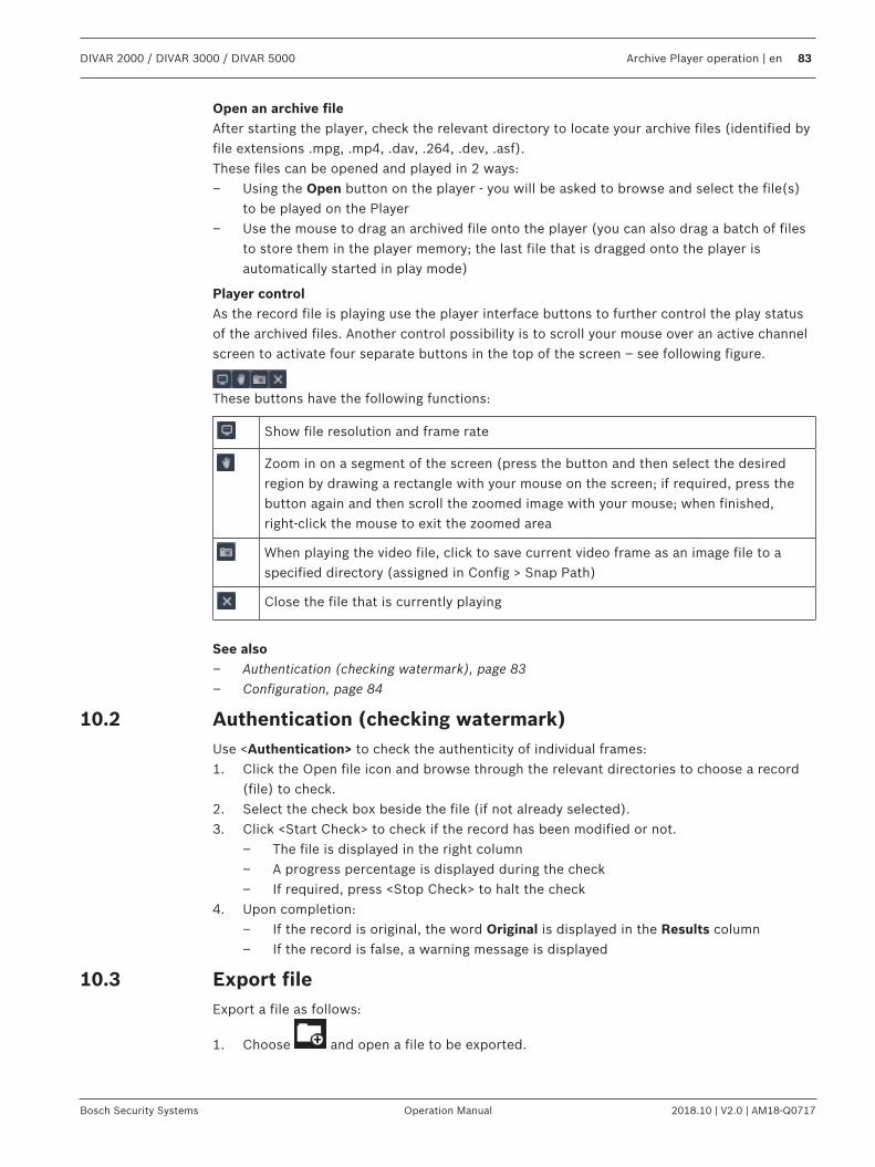
DIVAR 2000 / DIVAR 3000 / DIVAR 5000 Archive Player operation | en 83
Bosch Security Systems Operation Manual 2018.10 | V2.0 | AM18-Q0717
Open an archive fileAfter starting the player, check the relevant directory to locate your archive files (identified byfile extensions .mpg, .mp4, .dav, .264, .dev, .asf).These files can be opened and played in 2 ways:– Using the Open button on the player - you will be asked to browse and select the file(s)
to be played on the Player– Use the mouse to drag an archived file onto the player (you can also drag a batch of files
to store them in the player memory; the last file that is dragged onto the player isautomatically started in play mode)
Player controlAs the record file is playing use the player interface buttons to further control the play statusof the archived files. Another control possibility is to scroll your mouse over an active channelscreen to activate four separate buttons in the top of the screen – see following figure.
These buttons have the following functions:
Show file resolution and frame rate
Zoom in on a segment of the screen (press the button and then select the desiredregion by drawing a rectangle with your mouse on the screen; if required, press thebutton again and then scroll the zoomed image with your mouse; when finished,right-click the mouse to exit the zoomed area
When playing the video file, click to save current video frame as an image file to aspecified directory (assigned in Config > Snap Path)
Close the file that is currently playing
See also– Authentication (checking watermark), page 83– Configuration, page 84
10.2 Authentication (checking watermark)Use <Authentication> to check the authenticity of individual frames:1. Click the Open file icon and browse through the relevant directories to choose a record
(file) to check.2. Select the check box beside the file (if not already selected).3. Click <Start Check> to check if the record has been modified or not.
– The file is displayed in the right column– A progress percentage is displayed during the check– If required, press <Stop Check> to halt the check
4. Upon completion:– If the record is original, the word Original is displayed in the Results column– If the record is false, a warning message is displayed
10.3 Export fileExport a file as follows:
1. Choose and open a file to be exported.
84 en | Archive Player operation DIVAR 2000 / DIVAR 3000 / DIVAR 5000
2018.10 | V2.0 | AM18-Q0717 Operation Manual Bosch Security Systems
2. If required, preview the file on the left screen by selecting the check box for the chosenfile (if the file has multiple channels, select the check box for the required channel). Usethe play, pause, and fast forward/reverse buttons as required.
3. You can also overview the recording contents using the grid in the bottom of the screen.4. When you have decided on the recording segment that you wish to export, fill in the
setup fields (Export format, Start date, End date, Start time, End time, Interval) bymanually entering the field values. Or use the grid in the bottom of the screen to selectstart and end times.
5. Press <Start Export>.6. In the ‘Save as’ dialog box, choose a directory location and a file name for the export, and
press <Save>.A progress percentage is displayed during the exportIf required, press <Stop Export> to halt the export
7. When prompted, export the end of the file by pressing <OK>.
10.4 ConfigurationHere you can set:– Snap shot location - assign the path and directory to save a snapshot image (if necessary,
click on <Browse> and select a new path)– Snap format - select here the format (JPG or BMP) for the saved snapshot files– Language - choose here the language for the player user interface– Channel Display - select the checkbox to show the recorded channel information on the
video– Time Display - select the checkbox to show the recorded time information on the video
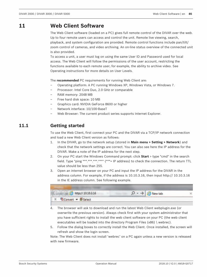
DIVAR 2000 / DIVAR 3000 / DIVAR 5000 Web Client Software | en 85
Bosch Security Systems Operation Manual 2018.10 | V2.0 | AM18-Q0717
11 Web Client SoftwareThe Web Client software (loaded on a PC) gives full remote control of the DIVAR over the web.Up to four remote users can access and control the unit. Remote live viewing, search,playback, and system configuration are provided. Remote control functions include pan/tilt/zoom control of cameras, and video archiving. An on-line status overview of the connected unitis also provided.To access a unit, a user must log on using the same User ID and Password used for localaccess. The Web Client will follow the permissions of the user account, restricting thefunctions available to each remote user; for example, the ability to archive video. SeeOperating instructions for more details on User Levels.
The recommended PC requirements for running Web Client are:– Operating platform: A PC running Windows XP, Windows Vista, or Windows 7.– Processor: Intel Core Duo, 2.0 GHz or comparable– RAM memory: 2048 MB– Free hard disk space: 10 MB– Graphics card: NVIDIA GeForce 8600 or higher– Network interface: 10/100-BaseT– Web Browser: The current product series supports Internet Explorer.
11.1 Getting startedTo use the Web Client, first connect your PC and the DIVAR via a TCP/IP network connectionand load a new Web Client version as follows:1. In the DIVAR, go to the network setup (stored in Main menu > Setting > Network) and
check that the network settings are correct. You can also see here the IP address for theDIVAR. Make a note of the IP address for the next step.
2. On your PC start the Windows Command prompt: click Start > type "cmd" in the searchfield. Type "ping ***.***.***.***" (***= IP address) to check the connection. The return TTLvalue should be less than 255.
3. Open an internet browser on your PC and input the IP address for the DIVAR in theaddress column. For example, if the address is 10.10.3.16, then input http:// 10.10.3.16in the IE address column. See following example.
4. The browser will ask to download and run the latest Web Client webplugin.exe (oroverwrite the previous version). Always check first with your system administrator thatyou have sufficient rights to install the web client software on your PC (the web clientexecutables will be loaded into the directory Program Files (x86) \ webrec).
5. Follow the dialog boxes to correctly install the Web Client. Once installed, the screen willrefresh and show the login screen.
Note: The Web Client does not install ‘webrec’ on a PC again unless a new version is releasedwith new firmware.
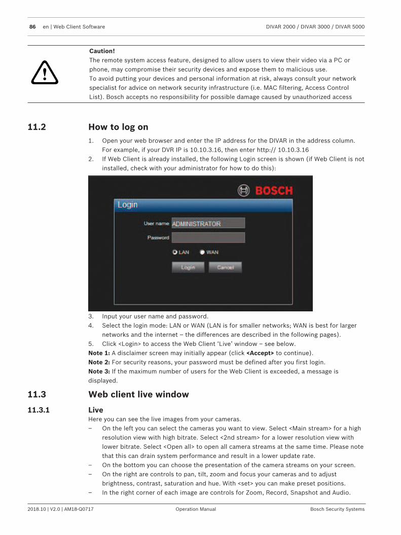
86 en | Web Client Software DIVAR 2000 / DIVAR 3000 / DIVAR 5000
2018.10 | V2.0 | AM18-Q0717 Operation Manual Bosch Security Systems
!
Caution!The remote system access feature, designed to allow users to view their video via a PC orphone, may compromise their security devices and expose them to malicious use.To avoid putting your devices and personal information at risk, always consult your networkspecialist for advice on network security infrastructure (i.e. MAC filtering, Access ControlList). Bosch accepts no responsibility for possible damage caused by unauthorized access
11.2 How to log on1. Open your web browser and enter the IP address for the DIVAR in the address column.
For example, if your DVR IP is 10.10.3.16, then enter http:// 10.10.3.162. If Web Client is already installed, the following Login screen is shown (if Web Client is not
installed, check with your administrator for how to do this):
3. Input your user name and password.4. Select the login mode: LAN or WAN (LAN is for smaller networks; WAN is best for larger
networks and the internet – the differences are described in the following pages).5. Click <Login> to access the Web Client ‘Live’ window – see below.Note 1: A disclaimer screen may initially appear (click <Accept> to continue).Note 2: For security reasons, your password must be defined after you first login.Note 3: If the maximum number of users for the Web Client is exceeded, a message isdisplayed.
11.3 Web client live window
11.3.1 LiveHere you can see the live images from your cameras.– On the left you can select the cameras you want to view. Select <Main stream> for a high
resolution view with high bitrate. Select <2nd stream> for a lower resolution view withlower bitrate. Select <Open all> to open all camera streams at the same time. Please notethat this can drain system performance and result in a lower update rate.
– On the bottom you can choose the presentation of the camera streams on your screen.– On the right are controls to pan, tilt, zoom and focus your cameras and to adjust
brightness, contrast, saturation and hue. With <set> you can make preset positions.– In the right corner of each image are controls for Zoom, Record, Snapshot and Audio.
DIVAR 2000 / DIVAR 3000 / DIVAR 5000 Web Client Software | en 87
Bosch Security Systems Operation Manual 2018.10 | V2.0 | AM18-Q0717
For more information see Live mode, page 66 and Pan/Tilt/Zoom, page 67 in the Operationchapter.
11.3.2 Playback modeClick the Playback button to search and playback your recordings. Here you can:– select different display modes (1 or 4 cameo displays, full screen)– assign cameras to cameos– press the user buttons to Play, Stop, Pause (with step-by-step forward and reverse play),
Reverse play, and adjust the play speed– turn audio off or on (and adjust volume)– jump to a specific date and time to view playback video– view a graphical timeline of the day for recording, input, or motion events– see unit status and alarm conditionsSee Playback, page 69 in the Operation chapter for a detailed description.
If your web connection has low bandwidth:– Only I-Frames are initially streamed to save bandwidth (in full screen, an I-Frame will be
streamed every second).– Playback starts at half-speed by default (the speed can be changed to single speed by
pressing FWD).– Exporting files may be slow.
11.3.3 Event searchClick Event search to search and playback a selected event.Choose here:– Type: Choose from All (default), Motion or Alarm– Channel: Choose All or specific channels– Start time: Choose start date and time for search– End time: Choose end date and time for searchPress <Search> to start the event search. The results are listed in the table. If required, scrollto a particular page in the list of events.To export the event file, press <Export>. A popup screen appears asking where to export thefile, and the file format. Fill in the fields and press <Export> again.The status bar shows the progress of the export.
11.3.4 ExportHere you can make a schedule for an automatic export (backup) of a recording.– Path: choose where to save the backup– Type: Select the type of video for back-up. Choose between: All, Regular, MD (motion
detection), Alarm– File format: DAV (default) or ASF– Bit stream type: Main stream (default) or 2nd stream– Start time: Fill in the date and start time of the backup. A backup can drain system
performance. Therefore, make your backups during a quiet period when features such aslocal playback/export are not required
– End time: Fill in the end date and time of the backup– Cam: Select the channel(s) to be backed up (default is All)Press <Add> to add this export to the schedule list below; add more scheduled backups asrequired. To remove a scheduled backup, select it on the list and press <Remove>. Press<Calculate> to calculate the expected size of the export.
88 en | Web Client Software DIVAR 2000 / DIVAR 3000 / DIVAR 5000
2018.10 | V2.0 | AM18-Q0717 Operation Manual Bosch Security Systems
Press <Start> to start the backup.The bottom of the screen shows the progress of the backup.
11.3.5 SettingClick <Setting> to enter the Setup menu where you can configure the settings for the unit.See Settings, page 32 for a description of options available here.Important: For safe HTTPS connections, you will require a trusted SSL Digital Certificate. Goto Setting > Network > HTTPS and follow the screen instructions to download and accept thecertificate (contact your system administrator if you have any questions).
11.3.6 InfoHere you can select various sub-menus to display important system information. See Info, page75 for more details.
11.3.7 LogoutClick <Logout> to log out of the system.
DIVAR 2000 / DIVAR 3000 / DIVAR 5000 DIVAR Mobile Viewer | en 89
Bosch Security Systems Operation Manual 2018.10 | V2.0 | AM18-Q0717
12 DIVAR Mobile ViewerThe DIVAR Mobile Viewer app gives the user remote access of the recorder with a wireless linkto their mobile device. Remote live viewing, search, playback, system configuration and alarmnotifications are provided. Remote control functions include pan/tilt/zoom control of cameras,and video archiving.To access a unit, a user must log on using the same User ID and Password used for localaccess. The DIVAR Mobile Viewer will follow the permissions of the user account, restrictingthe functions available to each remote user; for example, the ability to archive video.
12.1 Getting startedDownload the appIn order to use this device with the DIVAR Mobile Viewer app by Bosch, you must downloadthe app from Google Play, or from the Apple Store.You can access the app in several ways:– Scan the QR code from the DIVAR local viewer in Settings > Network > Mobile.– From Google Play Store (play.google.com), search for DIVAR Mobile Viewer. Select the
app from the list. Click the Install button.– From Apple Store (itunes.apple.com), search for DIVAR Mobile Viewer. Select the app
from the list. Click the appropriate button to download and install the app.
Add a recorderTo add a recorder to the mobile device:1. Open the DIVAR Mobile Viewer app.2. In the menu select Device Manager.3. Select the + button.4. Give the new device a name.5. Either:
– Select the scan QR code button and scan the QR code in the DIVAR local viewer inSettings > Network > Mobile
Or– Enter the IP address of the recorder.
6. If required change any other settings for the recorder. It is recommended to select thestream with the lowest bandwidth to reduce mobile data consumption. To do this, forLive Preview select Maininstead of Extra.
7. Enter the password and select the disk button to save.
12.2 Live PreviewHere you can see the live streams from your cameras. Pick a favorite view or a device viewfrom the top right menu button. Below the viewing windows the following controls can be set:– Choose the buttons to view 1, 4, 9 or 16 cameras at once. Swipe left or right to see the
next or previous view.– Select one of the delete buttons to delete one or more selected camera streams from the
view.– Switch on or off the speaker or microphone of a camera by selecting the speaker or
microphone button.– Take a snapshot or record video of the selected stream by selecting the snapshot or
record button.
On the bottom menu bar the following controls can be used:– Pan, tilt, zoom and focus controls for cameras that support these functions.
90 en | DIVAR Mobile Viewer DIVAR 2000 / DIVAR 3000 / DIVAR 5000
2018.10 | V2.0 | AM18-Q0717 Operation Manual Bosch Security Systems
– Select the favorites button to create new favorite views or choose already existingfavorites.
– Select the home button to return to the Live Preview.– Select the Playback button to go to the Playback page.– Select the Alarms button to configure the alarms for the selected camera.
For more information see Live mode, page 66 and Pan/Tilt/Zoom, page 67 in the Operationchapter.
12.3 PlaybackClick the Playback button to search and playback your recordings. Here you can:– Choose up to 4 views– press the user buttons to Play, Stop, Pause and reverse– turn audio off or on– jump to a specific date and time to view playback videoSee Playback, page 69 in the Operation chapter for a detailed description.
12.4 Device ManagerIn the Device Manager menu you can add a recorder or configure the settings of an existingrecorder.
Add a recorderTo add a recorder to the mobile device:1. Open the DIVAR Mobile Viewer app.2. In the menu select Device Manager.3. Select the + button.4. Give the new device a name.5. Either:
– Select the scan QR code button and scan the QR code in the DIVAR local viewer inSettings > Network > Mobile
Or– Enter the IP address of the recorder.
6. If required change any other settings for the recorder. It is recommended to select thestream with the lowest bandwidth to reduce mobile data consumption. To do this, forLive Preview select Maininstead of Extra.
7. Enter the password and select the disk button to save.
Configure the recorderWhen selecting a device in the device manager the following actions can be done:– Change the name and network settings of the device– Do a remote configuration of the device for the following settings:
– Video detect– Alarm setting– Camera setting (only for analog cameras)– Storage Manager– Notification
– Switch the alarm outputs of the device on or off.– View system information of the recorder such as the name, activity state, free and total
capacity.– Delete the recorder from your mobile device.
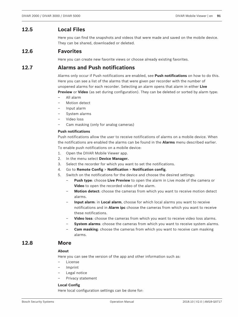
DIVAR 2000 / DIVAR 3000 / DIVAR 5000 DIVAR Mobile Viewer | en 91
Bosch Security Systems Operation Manual 2018.10 | V2.0 | AM18-Q0717
12.5 Local FilesHere you can find the snapshots and videos that were made and saved on the mobile device.They can be shared, downloaded or deleted.
12.6 FavoritesHere you can create new favorite views or choose already existing favorites.
12.7 Alarms and Push notificationsAlarms only occur if Push notifications are enabled, see Push notifications on how to do this.Here you can see a list of the alarms that were given per recorder with the number ofunopened alarms for each recorder. Selecting an alarm opens that alarm in either LivePreview or Video (as set during configuration). They can be deleted or sorted by alarm type:– All alarm– Motion detect– Input alarm– System alarms– Video loss– Cam masking (only for analog cameras)
Push notificationsPush notifications allow the user to receive notifications of alarms on a mobile device. Whenthe notifications are enabled the alarms can be found in the Alarms menu described earlier.To enable push notifications on a mobile device:1. Open the DIVAR Mobile Viewer app.2. In the menu select Device Manager.3. Select the recorder for which you want to set the notifications.4. Go to Remote Config > Notification > Notification config.5. Switch on the notifications for the device and choose the desired settings:
– Push type: choose Live Preview to open the alarm in Live mode of the camera orVideo to open the recorded video of the alarm.
– Motion detect: choose the cameras from which you want to receive motion detectalarms.
– Input alarm: in Local alarm, choose for which local alarms you want to receivenotifications and in Alarm ipc choose the cameras from which you want to receivethese notifications.
– Video loss: choose the cameras from which you want to receive video loss alarms.– System alarms: choose the cameras from which you want to receive system alarms.– Cam masking: choose the cameras from which you want to receive cam masking
alarms.
12.8 MoreAboutHere you can see the version of the app and other information such as:– License– Imprint– Legal notice– Privacy statement
Local ConfigHere local configuration settings can be done for:

92 en | DIVAR Mobile Viewer DIVAR 2000 / DIVAR 3000 / DIVAR 5000
2018.10 | V2.0 | AM18-Q0717 Operation Manual Bosch Security Systems
– PTZ step– Capture Mode– Real-time playback
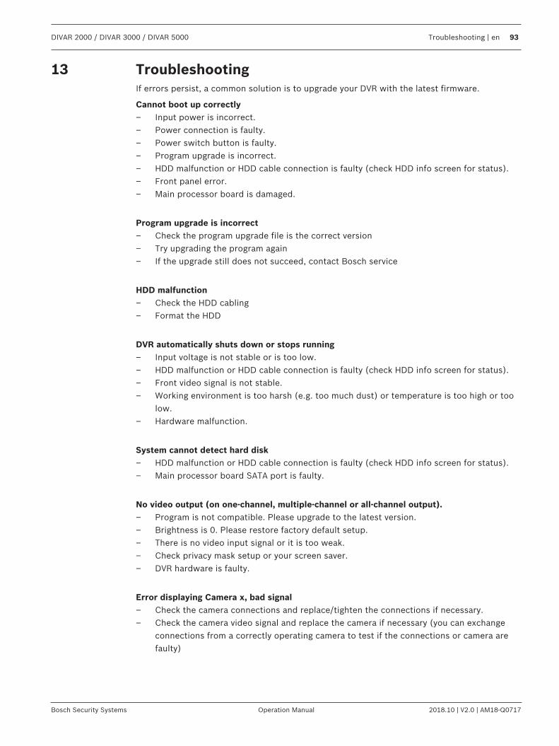
DIVAR 2000 / DIVAR 3000 / DIVAR 5000 Troubleshooting | en 93
Bosch Security Systems Operation Manual 2018.10 | V2.0 | AM18-Q0717
13 TroubleshootingIf errors persist, a common solution is to upgrade your DVR with the latest firmware.
Cannot boot up correctly– Input power is incorrect.– Power connection is faulty.– Power switch button is faulty.– Program upgrade is incorrect.– HDD malfunction or HDD cable connection is faulty (check HDD info screen for status).– Front panel error.– Main processor board is damaged.
Program upgrade is incorrect– Check the program upgrade file is the correct version– Try upgrading the program again– If the upgrade still does not succeed, contact Bosch service
HDD malfunction– Check the HDD cabling– Format the HDD
DVR automatically shuts down or stops running– Input voltage is not stable or is too low.– HDD malfunction or HDD cable connection is faulty (check HDD info screen for status).– Front video signal is not stable.– Working environment is too harsh (e.g. too much dust) or temperature is too high or too
low.– Hardware malfunction.
System cannot detect hard disk– HDD malfunction or HDD cable connection is faulty (check HDD info screen for status).– Main processor board SATA port is faulty.
No video output (on one-channel, multiple-channel or all-channel output).– Program is not compatible. Please upgrade to the latest version.– Brightness is 0. Please restore factory default setup.– There is no video input signal or it is too weak.– Check privacy mask setup or your screen saver.– DVR hardware is faulty.
Error displaying Camera x, bad signal– Check the camera connections and replace/tighten the connections if necessary.– Check the camera video signal and replace the camera if necessary (you can exchange
connections from a correctly operating camera to test if the connections or camera arefaulty)
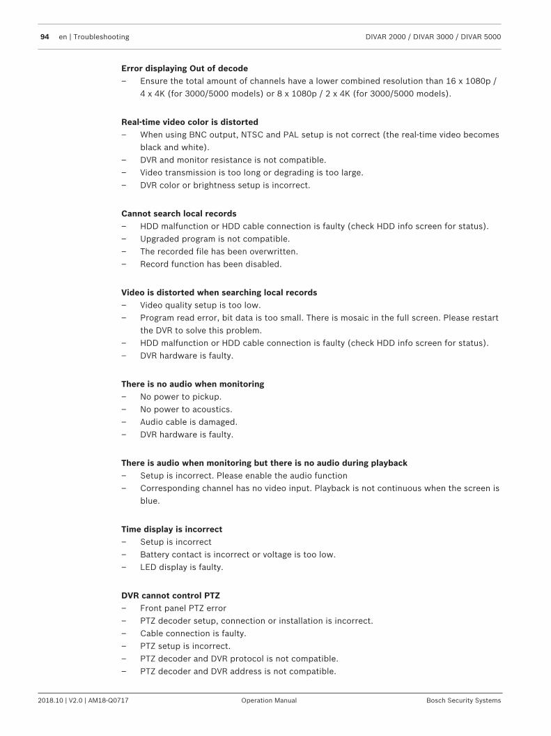
94 en | Troubleshooting DIVAR 2000 / DIVAR 3000 / DIVAR 5000
2018.10 | V2.0 | AM18-Q0717 Operation Manual Bosch Security Systems
Error displaying Out of decode– Ensure the total amount of channels have a lower combined resolution than 16 x 1080p /
4 x 4K (for 3000/5000 models) or 8 x 1080p / 2 x 4K (for 3000/5000 models).
Real-time video color is distorted– When using BNC output, NTSC and PAL setup is not correct (the real-time video becomes
black and white).– DVR and monitor resistance is not compatible.– Video transmission is too long or degrading is too large.– DVR color or brightness setup is incorrect.
Cannot search local records– HDD malfunction or HDD cable connection is faulty (check HDD info screen for status).– Upgraded program is not compatible.– The recorded file has been overwritten.– Record function has been disabled.
Video is distorted when searching local records– Video quality setup is too low.– Program read error, bit data is too small. There is mosaic in the full screen. Please restart
the DVR to solve this problem.– HDD malfunction or HDD cable connection is faulty (check HDD info screen for status).– DVR hardware is faulty.
There is no audio when monitoring– No power to pickup.– No power to acoustics.– Audio cable is damaged.– DVR hardware is faulty.
There is audio when monitoring but there is no audio during playback– Setup is incorrect. Please enable the audio function– Corresponding channel has no video input. Playback is not continuous when the screen is
blue.
Time display is incorrect– Setup is incorrect– Battery contact is incorrect or voltage is too low.– LED display is faulty.
DVR cannot control PTZ– Front panel PTZ error– PTZ decoder setup, connection or installation is incorrect.– Cable connection is faulty.– PTZ setup is incorrect.– PTZ decoder and DVR protocol is not compatible.– PTZ decoder and DVR address is not compatible.
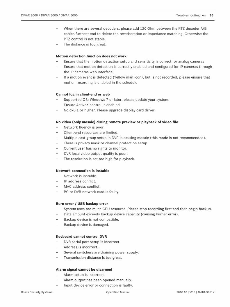
DIVAR 2000 / DIVAR 3000 / DIVAR 5000 Troubleshooting | en 95
Bosch Security Systems Operation Manual 2018.10 | V2.0 | AM18-Q0717
– When there are several decoders, please add 120 Ohm between the PTZ decoder A/Bcables furthest end to delete the reverberation or impedance matching. Otherwise thePTZ control is not stable.
– The distance is too great.
Motion detection function does not work– Ensure that the motion detection setup and sensitivity is correct for analog cameras– Ensure that motion detection is correctly enabled and configured for IP cameras through
the IP cameras web interface– If a motion event is detected (Yellow man icon), but is not recorded, please ensure that
motion recording is enabled in the schedule
Cannot log in client-end or web– Supported OS: Windows 7 or later, please update your system.– Ensure ActiveX control is enabled.– No dx8.1 or higher. Please upgrade display card driver.
No video (only mosaic) during remote preview or playback of video file– Network fluency is poor.– Client-end resources are limited.– Multiple-cast group setup in DVR is causing mosaic (this mode is not recommended).– There is privacy mask or channel protection setup.– Current user has no rights to monitor.– DVR local video output quality is poor.– The resolution is set too high for playback.
Network connection is instable– Network is instable.– IP address conflict.– MAC address conflict.– PC or DVR network card is faulty.
Burn error / USB backup error– System uses too much CPU resource. Please stop recording first and then begin backup.– Data amount exceeds backup device capacity (causing burner error).– Backup device is not compatible.– Backup device is damaged.
Keyboard cannot control DVR– DVR serial port setup is incorrect.– Address is incorrect.– Several switchers are draining power supply.– Transmission distance is too great.
Alarm signal cannot be disarmed– Alarm setup is incorrect.– Alarm output has been opened manually.– Input device error or connection is faulty.
96 en | Troubleshooting DIVAR 2000 / DIVAR 3000 / DIVAR 5000
2018.10 | V2.0 | AM18-Q0717 Operation Manual Bosch Security Systems
– Program version may be incorrect - please upgrade your system.
Alarm function is null– Alarm setup is incorrect.– Alarm cable connection is faulty.– Alarm input signal is incorrect.– Two loops connect to one alarm device.
Remote control does not work– Remote control address is incorrect.– Distance is too great or control angle is too small.– Remote control battery power is low.– Remote control or DVR front panel is damaged.
Record storage period is too short– Camera quality is too low.
– Lens is dirty– Camera is installed facing the light– Camera aperture setup is incorrect.
– HDD capacity is insufficient.– HDD is damaged.
Cannot playback the downloaded file– No media player.– No DXB8.1 (or higher) graphic acceleration software.– No DivX503Bundle.exe control when you play the file transformed to AVI via media player.– No DivX503Bundle.exe or ffdshow-2004 1012.exe in Windows XP OS.
Forgotten local menu operation password or network passwordPlease contact your local service engineer or Bosch sales group for help.
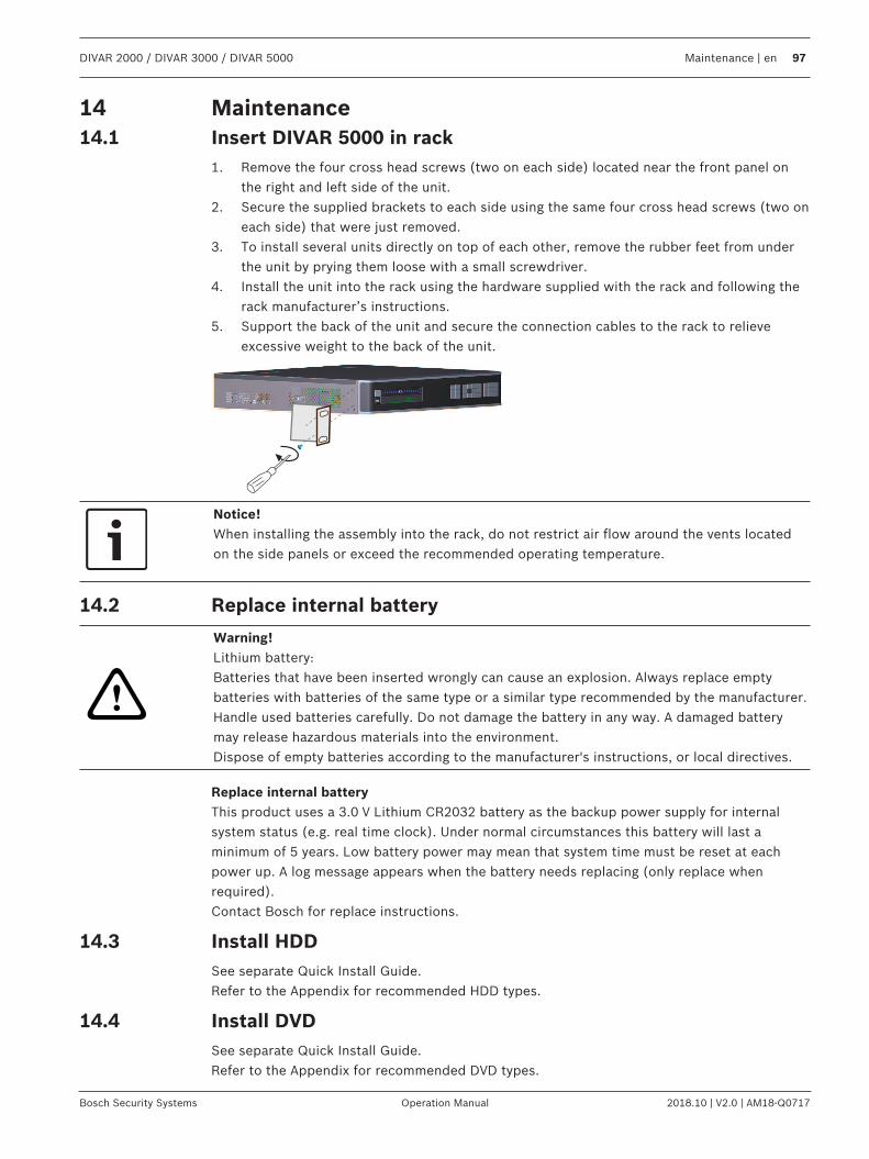
DIVAR 2000 / DIVAR 3000 / DIVAR 5000 Maintenance | en 97
Bosch Security Systems Operation Manual 2018.10 | V2.0 | AM18-Q0717
14 Maintenance14.1 Insert DIVAR 5000 in rack
1. Remove the four cross head screws (two on each side) located near the front panel onthe right and left side of the unit.
2. Secure the supplied brackets to each side using the same four cross head screws (two oneach side) that were just removed.
3. To install several units directly on top of each other, remove the rubber feet from underthe unit by prying them loose with a small screwdriver.
4. Install the unit into the rack using the hardware supplied with the rack and following therack manufacturer’s instructions.
5. Support the back of the unit and secure the connection cables to the rack to relieveexcessive weight to the back of the unit.
Notice!When installing the assembly into the rack, do not restrict air flow around the vents locatedon the side panels or exceed the recommended operating temperature.
14.2 Replace internal battery
!
Warning!Lithium battery:Batteries that have been inserted wrongly can cause an explosion. Always replace emptybatteries with batteries of the same type or a similar type recommended by the manufacturer.Handle used batteries carefully. Do not damage the battery in any way. A damaged batterymay release hazardous materials into the environment.Dispose of empty batteries according to the manufacturer's instructions, or local directives.
Replace internal batteryThis product uses a 3.0 V Lithium CR2032 battery as the backup power supply for internalsystem status (e.g. real time clock). Under normal circumstances this battery will last aminimum of 5 years. Low battery power may mean that system time must be reset at eachpower up. A log message appears when the battery needs replacing (only replace whenrequired).Contact Bosch for replace instructions.
14.3 Install HDDSee separate Quick Install Guide.Refer to the Appendix for recommended HDD types.
14.4 Install DVDSee separate Quick Install Guide.Refer to the Appendix for recommended DVD types.
98 en | Decommissioning DIVAR 2000 / DIVAR 3000 / DIVAR 5000
2018.10 | V2.0 | AM18-Q0717 Operation Manual Bosch Security Systems
15 Decommissioning15.1 Transfer
The unit should only be passed on together with this installation guide.
15.2 Disposal
Disposal - Your Bosch product was developed and manufactured with high-qualitymaterial and components that can be recycled and reused. This symbol means thatelectronic and electrical appliances, which have reached the end of their working life,must be collected and disposed of separately from household waste material.Separate collecting systems are usually in place for disused electronic and electricalproducts. Please dispose of these units at an environmentally compatible recyclingfacility, per European Directive 2012/19/EU.
DIVAR 2000 / DIVAR 3000 / DIVAR 5000 Technical data | en 99
Bosch Security Systems Operation Manual 2018.10 | V2.0 | AM18-Q0717
16 Technical dataEnvironmental
Operating temperature (incl.HDD(s) and DVD)
+0°C to +40°C (+32°F to +104°F)
Storage temperature -40°C to +70°C (-40°F to +158°F)
Operating humidity <93% non-condensing
Storage humidity <95% non-condensing
DIVAR 2000/3000
Mechanical
Dimensions (WxDxH) 375 x 323 x 53 mm (14.8 x 12.7 x 2.1 in)
Weight without PoE switch(excluding HDD(s) and DVD)
3.8 kg (8.4 lb) approx.
Weight with PoE switch(excluding HDD(s) and DVD)
4.2 kg (9.3 lb) approx.
Power
AC input (without PoE) 100-240 VAC; 50-60 Hz; 1.9 A
AC input (with PoE) 100-240 VAC; 50-60 Hz; 5 A
RTC battery on main PCB Lithium CR2032, 3 VDC
Power adapter DC output(without PoE)
12 VDC; 5 A
DVR Power input (withoutPoE)
12 VDC
Maximum main powerconsumption (no HDD)
8.7 W without PoE 15.2 W with PoE
Maximum power consumptionof PoE+ switch
185 W
Maximum power consumption(per PoE+ port)
25.5 W
DIVAR 5000
Mechanical
Dimensions (WxDxH) 440 x 408 x 76 mm (17.3 x 16.1 x 3.0 in)
Weight without PoE(excluding HDDs and DVD)
6.27 kg (13.8 lb) approx.
Weight with PoE switch(excluding HDDs and DVD)
6.37 kg (14.0 lb) approx.
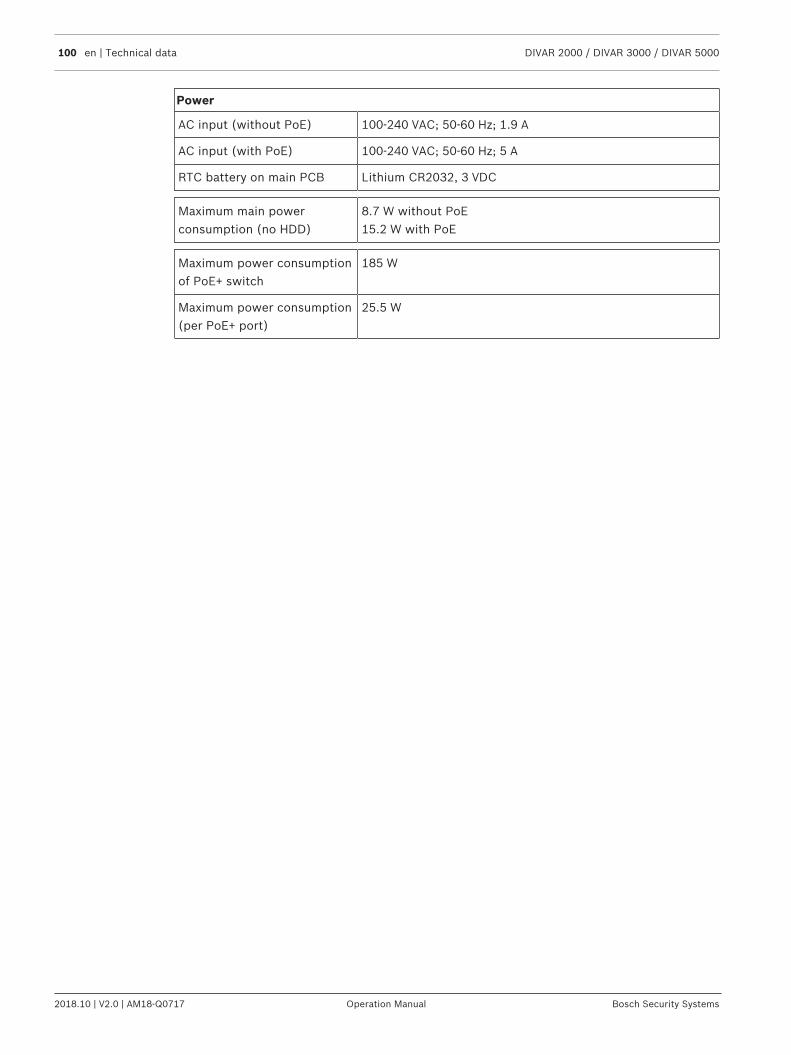
100 en | Technical data DIVAR 2000 / DIVAR 3000 / DIVAR 5000
2018.10 | V2.0 | AM18-Q0717 Operation Manual Bosch Security Systems
Power
AC input (without PoE) 100-240 VAC; 50-60 Hz; 1.9 A
AC input (with PoE) 100-240 VAC; 50-60 Hz; 5 A
RTC battery on main PCB Lithium CR2032, 3 VDC
Maximum main powerconsumption (no HDD)
8.7 W without PoE 15.2 W with PoE
Maximum power consumptionof PoE+ switch
185 W
Maximum power consumption(per PoE+ port)
25.5 W
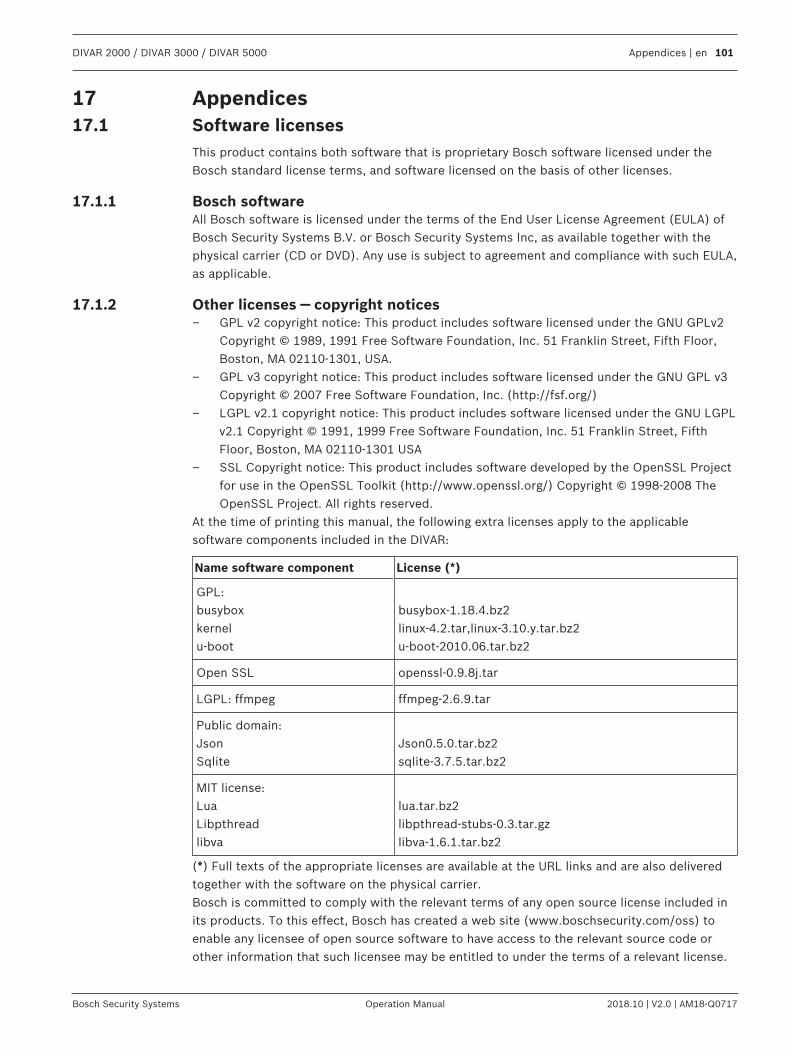
DIVAR 2000 / DIVAR 3000 / DIVAR 5000 Appendices | en 101
Bosch Security Systems Operation Manual 2018.10 | V2.0 | AM18-Q0717
17 Appendices17.1 Software licenses
This product contains both software that is proprietary Bosch software licensed under theBosch standard license terms, and software licensed on the basis of other licenses.
17.1.1 Bosch softwareAll Bosch software is licensed under the terms of the End User License Agreement (EULA) ofBosch Security Systems B.V. or Bosch Security Systems Inc, as available together with thephysical carrier (CD or DVD). Any use is subject to agreement and compliance with such EULA,as applicable.
17.1.2 Other licenses — copyright notices– GPL v2 copyright notice: This product includes software licensed under the GNU GPLv2
Copyright © 1989, 1991 Free Software Foundation, Inc. 51 Franklin Street, Fifth Floor,Boston, MA 02110-1301, USA.
– GPL v3 copyright notice: This product includes software licensed under the GNU GPL v3Copyright © 2007 Free Software Foundation, Inc. (http://fsf.org/)
– LGPL v2.1 copyright notice: This product includes software licensed under the GNU LGPLv2.1 Copyright © 1991, 1999 Free Software Foundation, Inc. 51 Franklin Street, FifthFloor, Boston, MA 02110-1301 USA
– SSL Copyright notice: This product includes software developed by the OpenSSL Projectfor use in the OpenSSL Toolkit (http://www.openssl.org/) Copyright © 1998-2008 TheOpenSSL Project. All rights reserved.
At the time of printing this manual, the following extra licenses apply to the applicablesoftware components included in the DIVAR:
Name software component License (*)
GPL:busyboxkernelu-boot
busybox-1.18.4.bz2linux-4.2.tar,linux-3.10.y.tar.bz2u-boot-2010.06.tar.bz2
Open SSL openssl-0.9.8j.tar
LGPL: ffmpeg ffmpeg-2.6.9.tar
Public domain:JsonSqlite
Json0.5.0.tar.bz2sqlite-3.7.5.tar.bz2
MIT license:LuaLibpthreadlibva
lua.tar.bz2libpthread-stubs-0.3.tar.gzlibva-1.6.1.tar.bz2
(*) Full texts of the appropriate licenses are available at the URL links and are also deliveredtogether with the software on the physical carrier.Bosch is committed to comply with the relevant terms of any open source license included inits products. To this effect, Bosch has created a web site (www.boschsecurity.com/oss) toenable any licensee of open source software to have access to the relevant source code orother information that such licensee may be entitled to under the terms of a relevant license.
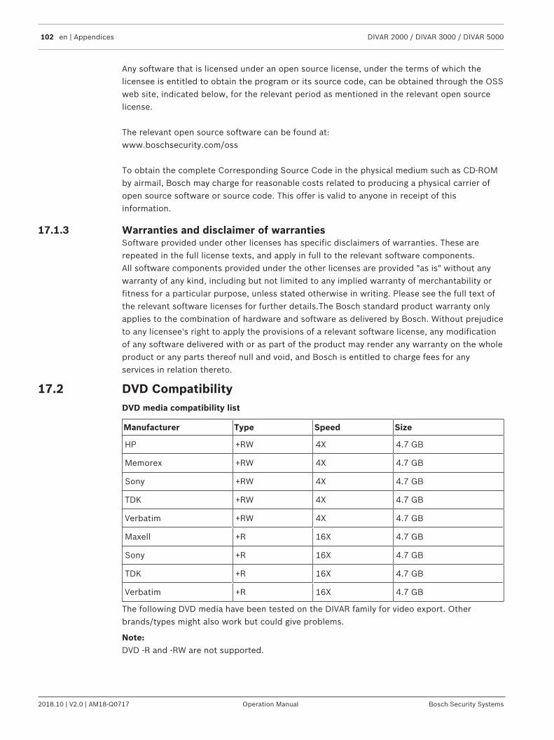
102 en | Appendices DIVAR 2000 / DIVAR 3000 / DIVAR 5000
2018.10 | V2.0 | AM18-Q0717 Operation Manual Bosch Security Systems
Any software that is licensed under an open source license, under the terms of which thelicensee is entitled to obtain the program or its source code, can be obtained through the OSSweb site, indicated below, for the relevant period as mentioned in the relevant open sourcelicense.
The relevant open source software can be found at:www.boschsecurity.com/oss
To obtain the complete Corresponding Source Code in the physical medium such as CD-ROMby airmail, Bosch may charge for reasonable costs related to producing a physical carrier ofopen source software or source code. This offer is valid to anyone in receipt of thisinformation.
17.1.3 Warranties and disclaimer of warrantiesSoftware provided under other licenses has specific disclaimers of warranties. These arerepeated in the full license texts, and apply in full to the relevant software components.All software components provided under the other licenses are provided "as is" without anywarranty of any kind, including but not limited to any implied warranty of merchantability orfitness for a particular purpose, unless stated otherwise in writing. Please see the full text ofthe relevant software licenses for further details.The Bosch standard product warranty onlyapplies to the combination of hardware and software as delivered by Bosch. Without prejudiceto any licensee's right to apply the provisions of a relevant software license, any modificationof any software delivered with or as part of the product may render any warranty on the wholeproduct or any parts thereof null and void, and Bosch is entitled to charge fees for anyservices in relation thereto.
17.2 DVD CompatibilityDVD media compatibility list
Manufacturer Type Speed Size
HP +RW 4X 4.7 GB
Memorex +RW 4X 4.7 GB
Sony +RW 4X 4.7 GB
TDK +RW 4X 4.7 GB
Verbatim +RW 4X 4.7 GB
Maxell +R 16X 4.7 GB
Sony +R 16X 4.7 GB
TDK +R 16X 4.7 GB
Verbatim +R 16X 4.7 GB
The following DVD media have been tested on the DIVAR family for video export. Otherbrands/types might also work but could give problems.
Note:DVD -R and -RW are not supported.
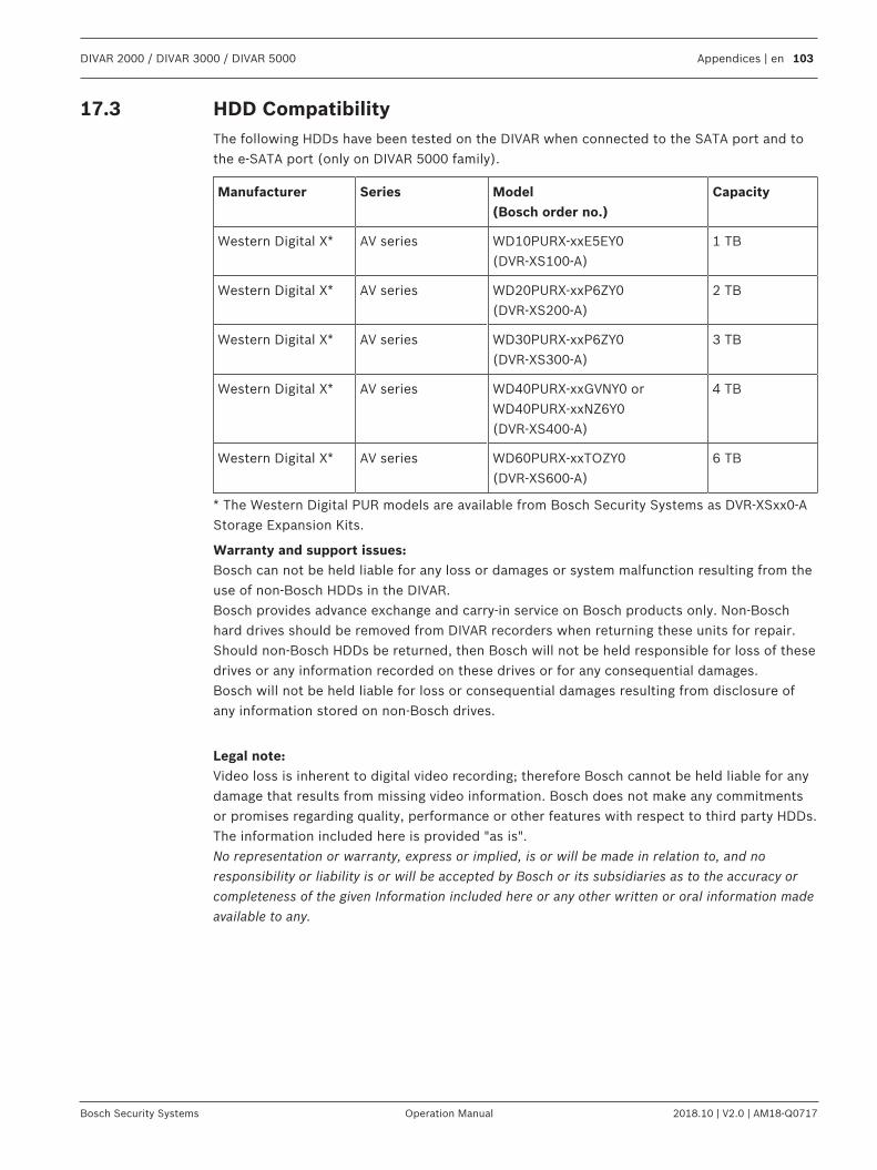
DIVAR 2000 / DIVAR 3000 / DIVAR 5000 Appendices | en 103
Bosch Security Systems Operation Manual 2018.10 | V2.0 | AM18-Q0717
17.3 HDD CompatibilityThe following HDDs have been tested on the DIVAR when connected to the SATA port and tothe e-SATA port (only on DIVAR 5000 family).
Manufacturer Series Model(Bosch order no.)
Capacity
Western Digital X* AV series WD10PURX-xxE5EY0(DVR-XS100-A)
1 TB
Western Digital X* AV series WD20PURX-xxP6ZY0(DVR-XS200-A)
2 TB
Western Digital X* AV series WD30PURX-xxP6ZY0(DVR-XS300-A)
3 TB
Western Digital X* AV series WD40PURX-xxGVNY0 orWD40PURX-xxNZ6Y0(DVR-XS400-A)
4 TB
Western Digital X* AV series WD60PURX-xxTOZY0(DVR-XS600-A)
6 TB
* The Western Digital PUR models are available from Bosch Security Systems as DVR-XSxx0-AStorage Expansion Kits.
Warranty and support issues:Bosch can not be held liable for any loss or damages or system malfunction resulting from theuse of non-Bosch HDDs in the DIVAR.Bosch provides advance exchange and carry-in service on Bosch products only. Non-Boschhard drives should be removed from DIVAR recorders when returning these units for repair.Should non-Bosch HDDs be returned, then Bosch will not be held responsible for loss of thesedrives or any information recorded on these drives or for any consequential damages.Bosch will not be held liable for loss or consequential damages resulting from disclosure ofany information stored on non-Bosch drives.
Legal note:Video loss is inherent to digital video recording; therefore Bosch cannot be held liable for anydamage that results from missing video information. Bosch does not make any commitmentsor promises regarding quality, performance or other features with respect to third party HDDs.The information included here is provided "as is".No representation or warranty, express or implied, is or will be made in relation to, and noresponsibility or liability is or will be accepted by Bosch or its subsidiaries as to the accuracy orcompleteness of the given Information included here or any other written or oral information madeavailable to any.


Bosch Security Systems B.V.Torenallee 495617 BA EindhovenNetherlandswww.boschsecurity.com© Bosch Security Systems B.V., 2018


