115
DL205 Installation and I/O Manual Manual Number: D2-INST-M

DL205 Installation and I/O Manual
Manual Number: D2-INST-M

~ WARNING ~Thank you for purchasing automation equipment from AutomationDirect.com®, doing business as, AutomationDirect. We want your new automation equipment to operate safely. Anyone who installs or uses this equipment should read this publication (and any other relevant publications) before installing or operating the equipment.
To minimize the risk of potential safety problems, you should follow all applicable local and national codes that regulate the installation and operation of your equipment. These codes vary from area to area and usually change with time. It is your responsibility to determine which codes should be followed, and to verify that the equipment, installation, and operation is in compliance with the latest revision of these codes.
At a minimum, you should follow all applicable sections of the National Fire Code, National Electrical Code, and the codes of the National Electrical Manufacturer’s Association (NEMA). There may be local regulatory or government offices that can also help determine which codes and standards are necessary for safe installation and operation.
Equipment damage or serious injury to personnel can result from the failure to follow all applicable codes and standards. We do not guarantee the products described in this publication are suitable for your particular application, nor do we assume any responsibility for your product design, installation, or operation.
Our products are not fault-tolerant and are not designed, manufactured or intended for use or resale as on-line control equipment in hazardous environments requiring fail-safe performance, such as in the operation of nuclear facilities, aircraft navigation or communication systems, air traffic control, direct life support machines, or weapons systems, in which the failure of the product could lead directly to death, personal injury, or severe physical or environmental damage (“High Risk Activities”). AutomationDirect specifically disclaims any expressed or implied warranty of fitness for High Risk Activities.
For additional warranty and safety information, see the Terms and Conditions section of our catalog. If you have any questions concerning the installation or operation of this equipment, or if you need additional information, please call us at 770-844-4200.
This publication is based on information that was available at the time it was printed. At AutomationDirect we constantly strive to improve our products and services, so we reserve the right to make changes to the products and/or publications at any time without notice and without any obligation. This publication may also discuss features that may not be available in certain revisions of the product.
TrademarksThis publication may contain references to products produced and/or offered by other companies. The product and company names may be trademarked and are the sole property of their respective owners. AutomationDirect disclaims any proprietary interest in the marks and names of others.
Copyright 2020 AutomationDirect.com Incorporated All Rights Reserved
No part of this manual shall be copied, reproduced, or transmitted in any way without the prior, written consent of AutomationDirect.com Incorporated. AutomationDirect retains the exclusive rights to all information included in this document.

~ ADVERTENCIA ~Gracias por comprar equipo de automatización de Automationdirect.com®. Deseamos que su nuevo equipo de automatización opere de manera segura. Cualquier persona que instale o use este equipo debe leer esta publicación (y cualquier otra publicación pertinente) antes de instalar u operar el equipo.
Para reducir al mínimo el riesgo debido a problemas de seguridad, debe seguir todos los códigos de seguridad locales o nacionales aplicables que regulan la instalación y operación de su equipo. Estos códigos varian de área en área y usualmente cambian con el tiempo. Es su responsabilidad determinar cuales códigos deben ser seguidos y verificar que el equipo, instalación y operación estén en cumplimiento con la revisión mas reciente de estos códigos.
Como mínimo, debe seguir las secciones aplicables del Código Nacional de Incendio, Código Nacional Eléctrico, y los códigos de (NEMA) la Asociación Nacional de Fabricantes Eléctricos de USA. Puede haber oficinas de normas locales o del gobierno que pueden ayudar a determinar cuales códigos y normas son necesarios para una instalación y operación segura.
Si no se siguen todos los códigos y normas aplicables, puede resultar en daños al equipo o lesiones serias a personas. No garantizamos los productos descritos en esta publicación para ser adecuados para su aplicación en particular, ni asumimos ninguna responsabilidad por el diseño de su producto, la instalación u operación.
Nuestros productos no son tolerantes a fallas y no han sido diseñados, fabricados o intencionados para uso o reventa como equipo de control en línea en ambientes peligrosos que requieren una ejecución sin fallas, tales como operación en instalaciones nucleares, sistemas de navegación aérea, o de comunicación, control de tráfico aéreo, máquinas de soporte de vida o sistemas de armamentos en las cuales la falla del producto puede resultar directamente en muerte, heridas personales, o daños físicos o ambientales severos (“Actividades de Alto Riesgo”). Automationdirect.com específicamente rechaza cualquier garantía ya sea expresada o implicada para actividades de alto riesgo. Para información adicional acerca de garantía e información de seguridad, vea la sección de Términos y Condiciones de nuestro catálogo. Si tiene alguna pregunta sobre instalación u operación de este equipo, o si necesita información adicional, por favor llámenos al número 770-844-4200 en Estados Unidos. Esta publicación está basada en la información disponible al momento de impresión. En Automationdirect.com nos esforzamos constantemente para mejorar nuestros productos y servicios, así que nos reservamos el derecho de hacer cambios al producto y/o a las publicaciones en cualquier momento sin notificación y sin ninguna obligación. Esta publicación también puede discutir características que no estén disponibles en ciertas revisiones del producto.
Marcas RegistradasEsta publicación puede contener referencias a productos producidos y/u ofrecidos por otras compañías. Los nombres de las compañías y productos pueden tener marcas registradas y son propiedad única de sus respectivos dueños. Automationdirect.com, renuncia cualquier interés propietario en las marcas y nombres de otros.
PROPIEDAD LITERARIA 2020, AUTOMATIONDIRECT.COM® INCORPORATEDTodos los derechos reservados
No se permite copiar, reproducir, o transmitir de ninguna forma ninguna parte de este manual sin previo consentimiento por escrito de Automationdirect.com® Incorprated. Automationdirect.com retiene los derechos exclusivos a toda la información incluida en este documento. Los usuarios de este equipo pueden copiar este documento solamente para instalar, configurar y mantener el equipo correspondiente. También las instituciones de enseñanza pueden usar este manual para propósitos educativos.

DL205 InstaLLatIon anD I/o MANUAL
Please include the Manual Number and the Manual Issue, both shown below, when communicating with Technical Support regarding this publication.
Manual Number: D2-INST-M
Issue: 2nd Edition, Revision A
Issue Date: 02/20
Publication HistoryIssue Date Description of Changes
1st Edition 10/98 Original editionRev. A 04/01 Added modulesRev. B 06/02 Added surge suppression information and modules; updated Appendix A
2nd Edition 11/10 Converted to new word processor format, added power budget, added analog wiring and specs.
Rev. A 02/20 Converted to InDesign format with general updates

Table of ConTenTs
Chapter 1: IntroductionIntroduction ...............................................................................................................1–2
The Purpose of this Manual ......................................................................................1–2Where to Begin ........................................................................................................1–2Supplemental Manuals .............................................................................................1–2Technical Support ....................................................................................................1–2
Conventions Used ......................................................................................................1–3Key Topics for Each Chapter .....................................................................................1–3
CPU-Slot Controllers ..................................................................................................1–4
DL205 System I/O Components ................................................................................1–5Bases ........................................................................................................................1–5I/O Configuration .....................................................................................................1–5I/O Modules .............................................................................................................1–5
Chapter 2: Installation and Power WiringSafety Guidelines .......................................................................................................2–2
Plan for Safety ..........................................................................................................2–2Three Levels of Protection ........................................................................................2–3Emergency Stops ......................................................................................................2–3Emergency Power Disconnect ..................................................................................2–4Orderly System Shutdown ........................................................................................2–4Class 1, Division 2, Approval ....................................................................................2–4
Mounting Guidelines .................................................................................................2–5Base Dimensions ......................................................................................................2–5Panel Mounting and Layout .....................................................................................2–6Enclosures ................................................................................................................2–7Environmental Specifications ....................................................................................2–8

DL205 Installation and I/O Manual, 2nd Ed., Rev. A
Table of Contents
ii
Power .......................................................................................................................2–8Marine Use ...............................................................................................................2–9Agency Approvals ....................................................................................................2–924VDC Power Bases .................................................................................................2–9
Installing DL205 Bases .............................................................................................2–10Choosing the Base Type .........................................................................................2–10Mounting the Base .................................................................................................2–10Using Mounting Rails .............................................................................................2–11
Installing Components in the Base .........................................................................2–12
Base Wiring Guidelines............................................................................................2–13Base Wiring ............................................................................................................2–13
Chapter 3: I/O Wiring and SpecificationI/O Wiring Strategies ................................................................................................3–2
PLC Isolation Boundaries ..........................................................................................3–2Powering I/O Circuits with the Auxiliary Supply .......................................................3–3Powering I/O Circuits Using Separate Supplies .........................................................3–4Sinking / Sourcing Concepts ....................................................................................3–5I/O “Common” Terminal Concepts ..........................................................................3–6Connecting DC I/O to “Solid State” Field Devices ....................................................3–7Solid State Input Sensors ..........................................................................................3–7Solid State Output Loads ..........................................................................................3–7Relay Output Guidelines ...........................................................................................3–9Surge Suppression For Inductive Loads .....................................................................3–9
I/O Modules Position, Wiring, and Specification ...................................................3–13Slot Numbering......................................................................................................3–13Module Placement Restrictions ...............................................................................3–13Special Placement Considerations for Analog Modules ..........................................3–14Discrete Input Module Status Indicators .................................................................3–14Color Coding of I/O Modules .................................................................................3–14Wiring the Different Module Connectors ................................................................3–15I/O Wiring Checklist ...............................................................................................3–16I/O Points Required for Each Module .....................................................................3–17
Calculating the Power Budget ................................................................................3–18Managing your Power Resource .............................................................................3–18
DL205 Installation and I/O Manual, 2nd Ed., Rev. A
Table of Contents
iii
CPU Power Specifications .......................................................................................3–18Module Power Requirements ..................................................................................3–18Power Budget Calculation Example ........................................................................3–20Power Budget Calculation Worksheet .....................................................................3–21
DL205 Digital Input Modules ..................................................................................3–22D2-16ND3-2, DC Input ..........................................................................................3–22D2-08ND3, DC Input .............................................................................................3–22D2–32ND3, DC Input ............................................................................................3–23D2–32ND3–2, DC Input .........................................................................................3–24D2-08NA-1, AC Input .............................................................................................3–25D2-08NA-2, AC Input .............................................................................................3–26F2-08SIM, Input Simulator ....................................................................................3–27D2-16NA, AC Input ................................................................................................3–27D2-04TD1, DC Output ...........................................................................................3–28
DL205 Digital Output Modules ...............................................................................3–28D2–08TD2, DC Output ..........................................................................................3–29D2–08TD1, DC Output ..........................................................................................3–29D2–16TD2–2, DC Output ......................................................................................3–30D2–16TD1–2, DC Output ......................................................................................3–30F2–16TD1(2)P, DC Output With Fault Protection ...................................................3–31F2–16TD1P, DC Output With Fault Protection ......................................................3–32F2–16TD2P, DC Output with Fault Protection ........................................................3–33D2–32TD2, DC Output ..........................................................................................3–34D2–32TD1, DC Output ..........................................................................................3–34D2–08TA, AC Output ............................................................................................3–35F2–08TA, AC Output ..............................................................................................3–35D2–12TA, AC Output .............................................................................................3–36D2–04TRS, Relay Output ........................................................................................3–37D2–08TR, Relay Output ..........................................................................................3–38F2–08TR, Relay Output...........................................................................................3–39F2–08TRS, Relay Output .........................................................................................3–40D2–12TR, Relay Output ..........................................................................................3–41D2–08CDR, 4 pt. DC Input / 4pt. Relay Output .....................................................3–42
DL205 Analog Input Modules .................................................................................3–44F2-04AD-1 4-Channel 4-20mA Analog Input Module ............................................3–44

DL205 Installation and I/O Manual, 2nd Ed., Rev. A
Table of Contents
iv
F2-08AD-1 8-Channel 4-20mA Analog Input Module ............................................3–46F2-04AD-2 4-Channel Voltage Analog Input Module ............................................3–48F2-08AD-2 8-Channel Voltage Analog Input Module ............................................3–50
DL205 RTD and Thermocouple Modules ................................................................3–52F2-04RTD 4-Channel RTD Input Module ...............................................................3–52F2-04THM 4-Channel Thermocouple Input Module ..............................................3–54
DL205 Analog Output Modules ..............................................................................3–56F2-02DA-1 2-Channel 4-20mA Analog Output Module .........................................3–56F2-02DA-1L 2-Channel 4-20mA Analog Output Module .......................................3–58F2-02DAS-1 2-Channel Isolated 4-20mA Analog Output Module ..........................3–60F2-08DA-1 8-Channel 4-20mA Analog Output Module........................................3–62F2-02DA-2 2-Channel Voltage Analog Output Module ........................................3–64F2-02DA-2L 2-Channel Voltage Analog Output Module .......................................3–66F2-02DAS-2 2-Channel 0-5V, 0-10V Isolated Analog Output Module ...................3–68F2-08DA-2 8-Channel Voltage Analog Output Module .........................................3–70
DL205 Combination Analog I/O Modules ..............................................................3–72F2-04AD2DA 4-Channel Analog Input / 2-Channel Analog Output Module ..........3–72F2-08AD4DA-1 8-Channel Analog Current Input / 4-Channel Analog Current ............. Output Module ......................................................................................................3–74F2-08AD4DA-2 8-Channel Analog Voltage Input / 4-Channel Analog Voltage ............. Output Module ......................................................................................................3–76
Glossary of Specification Terms .............................................................................3–78Inputs or Outputs Per Module ...............................................................................3–78Commons Per Module ...........................................................................................3–78Input Voltage Range ...............................................................................................3–78Output Voltage Range ............................................................................................3–78Peak Voltage ..........................................................................................................3–78AC Frequency .........................................................................................................3–78ON Voltage Level ...................................................................................................3–78OFF Voltage Level...................................................................................................3–78Input impedance ....................................................................................................3–78Input Current .........................................................................................................3–78Minimum ON Current ............................................................................................3–78Maximum OFF Current ..........................................................................................3–78Minimum Load.......................................................................................................3–78

DL205 Installation and I/O Manual, 2nd Ed., Rev. A
Table of Contents
v
External DC Required .............................................................................................3–78ON Voltage Drop ...................................................................................................3–78Maximum Leakage Current ....................................................................................3–79Maximum Inrush Current .......................................................................................3–79Base Power Required ..............................................................................................3–79OFF to ON Response ..............................................................................................3–79ON to OFF Response ..............................................................................................3–79Terminal Type ........................................................................................................3–79Status Indicators .....................................................................................................3–79Fuses ......................................................................................................................3–79
Appendix A: European Union (EU) DirectivesEuropean Union (EU) Directives ............................................................................... A-2
Member Countries ................................................................................................... A-2Applicable Directives ................................................................................................ A-2Compliance .............................................................................................................. A-2General Safety .......................................................................................................... A-3Special Installation Manual ....................................................................................... A-4Other Sources of Information ................................................................................... A-4
Basic EMC Installation Guidelines ............................................................................. A-4Enclosures ................................................................................................................ A-4AC Mains Filters ....................................................................................................... A-5Suppression and Fusing ............................................................................................ A-5Internal Enclosure Grounding ................................................................................... A-5Equi–potential Grounding ........................................................................................ A-6Communications and Shielded Cables ..................................................................... A-6Analog and RS232 Cables ........................................................................................ A-7Shielded Cables within Enclosures ............................................................................ A-7Analog Modules and RF Interference ........................................................................ A-8Network Isolation ..................................................................................................... A-8DC Powered Versions ............................................................................................... A-8Items Specific to the DL205 ..................................................................................... A-9

IntroductIon 111ChapterChapterChapter
In This Chapter...Introduction ...............................................................................................................1–2
Conventions Used ......................................................................................................1–3
CPU-Slot Controllers ..................................................................................................1–4
DL205 System I/O Components ................................................................................1–5

DL205 Installation and I/O Manual, 2nd Ed., Rev. A1–2
Chapter 1: Introduction
IntroductionThe Purpose of this Manual
Thank you for purchasing our DL205 family of products. This manual is written for the user of non-traditional CPU-slot controllers or I/O controllers who are also using AutomationDirect DL205 I/O products. This manual will show the user how to install and wire the equipment. It provides specifications for input and output modules. It also helps to understand how to interface these products to other devices in a control system.
Where to BeginIf you already understand PLCs please read Chapter 2, “Installation, Wiring, and Specifications”, and proceed on to other chapters as needed. Keep this manual handy for reference when you have questions. If you are a new DL205 customer, we suggest you read this manual completely to understand the wide variety of features in the DL205 family of products. We believe you will be pleasantly surprised with how much you can accomplish with our products.
Supplemental Manuals If you have purchased operator interfaces or DirectSOFT, you will need to supplement this manual with the manuals that are written for these products.
Technical SupportWe strive to make our manuals the best in the industry. We rely on your feedback to let us know if we are reaching our goal. If you cannot find the solution to your particular application, or, if for any reason you need technical assistance, please call us at:
770–844–4200
Our technical support group will work with you to answer your questions. They are available Monday through Friday from 9:00 A.M. to 6:00 P.M. Eastern Time. We also encourage you to visit our web site where you can find technical and non-technical information about our products and our company.
http://www.automationdirect.com
If you have a comment, question or suggestion about any of our products, services, or manuals, please fill out and return the ‘Suggestions’ card that was included with this manual.

DL205 Installation and I/O Manual, 2nd Ed., Rev. A 1–3
Chapter 1: Introduction
Conventions Used
When you see the “notepad” icon in the left–hand margin, the paragraph to its immediate right will be a special note. The word NOTE in boldface will mark the beginning of the text.
When you see the “exclamation mark” icon in the left–hand margin, the paragraph to its immediate right will be a warning. This information could prevent injury, loss of property, or even death (in extreme cases). The word WARNING in boldface will mark the beginning of the text.
Key Topics for Each ChapterThe beginning of each chapter will list the key topics that can be found in that chapter.
Getting Started CHAPTER
1In This Chapter...
.................................................................1-2...........................................................................1-4Specifications
General Information

DL205 Installation and I/O Manual, 2nd Ed., Rev. A1–4
Chapter 1: Introduction
CPU-Slot ControllersThere are currently six “base controllers” or “I/O controllers available for the DL205 hardware. Five of these are actually slave controllers and one is a stand-alone controller. These controllers allow the use of industry proven DL205 I/O for general purpose distributed applications.
The controller modules are plugged into the CPU slot of any size DL205 base. The slave controllers must be connected to a network master controller module or to a PC running PC-based control, HMI or SCADA software.
The four controllers currently available are:
• Ethernet Base Controller Module - H2-EBC(100)(-F)
• Profibus Slave Base Controller Module
- H2-PBC
• DeviceNet TM Slave Module - F2-DEVNETS-1
• Smart Distributed System TM Slave Module - F2-SDS-1
• WinPLC
- H2-WPLCx-xx
The WinPLC uses Windows CE, a real-time operating system combined with the advantages of open standard software such as OPC, ActiveX and other Microsoft communications tools. The WinPLC only supports certain DL205 modules (consult the WinPLC User Manual).
detratS gnitte
G
H2–EBC–F F2–DEVNETS–1 F2–SDS–1 H2–WPLCx–xxH2–PBCH2–EBC(100)

DL205 Installation and I/O Manual, 2nd Ed., Rev. A 1–5
Chapter 1: Introduction
DL205 System I/O ComponentsBases
Four base sizes are available: 3 slot, 4 slot, 6 slot and 9 slot. One slot is for the DL205 Controller/Slave module, the remaining slots are for I/O modules. All bases include a built-in power supply.
I/O ConfigurationThe number of I/O points that can be supported is CPU-slot controller dependent.
I/O ModulesThe DL205 has some of the most powerful modules in the industry. A complete range of discrete modules which support 24VDC, 110/220 VAC and up to 10A relay outputs are offered. The analog modules provide 12 and 16 bit resolution and several selections of input and output signal ranges (including bipolar).
The F2-SDS-1 and F2-DEVNETS-1 do not support specialty modules. Specialty module H2-CTRIO is supported by the other slave controllers and the H2-WPLCx-xx controller.

InstallatIon, WIrIng and specIfIcatIons 122
ChapterChapterChapter
In This Chapter...Safety Guidelines .......................................................................................................2–1
Mounting Guidelines .................................................................................................2–4
Installing DL205 Bases ...............................................................................................2–9
Installing Components in the Base .........................................................................2–11
Base Wiring Guidelines ............................................................................................2–12
DL205 Installation and I/O Manual, 2nd Ed., Rev. A 2–7
Chapter 2: Installation and Wiring
Safety GuidelinesNOTE: Products with CE marks perform their required functions safely and adhere to relevant standards as specified by CE directives, provided they are used according to their intended purpose and that the instructions in this manual are adhered to. The protection provided by the equipment may be impaired if this equipment is used in a manner not specified in this manual. A listing of our international affiliates is available on our Web site: http://www.automationdirect.com
WARNING: Providing a safe operating environment for personnel and equipment is your responsibility and should be your primary goal during system planning and installation. Automation systems can fail and may result in situations that can cause serious injury to personnel and/or damage equipment. Do not rely on the automation system alone to provide a safe operating environment. Sufficient emergency circuits should be provided to stop either partially or totally the operation of the PLC or the controlled machine or process. These circuits should be routed outside the PLC in the event of controller failure, so that independent and rapid shutdown are available. Devices, such as “mushroom” switches or end of travel limit switches, should operate motor starter, solenoids, or other devices without being processed by the PLC. These emergency circuits should be designed using simple logic with a minimum number of highly reliable electromechanical components. Every automation application is different, so there may be special requirements for your particular application. Make sure all national, state, and local government requirements are followed for the proper installation and use of your equipment.
Plan for SafetyThe best way to provide a safe operating environment is to make personnel and equipment safety part of the planning process. You should examine every aspect of the system to determine which areas are critical to operator or machine safety.
If you are not familiar with PLC system installation practices, or your company does not have established installation guidelines, you should obtain additional information from the following sources.
• NEMA — The National Electrical Manufacturers Association, located in Washington, D.C., publishes many different documents that discuss standards for industrial control systems. You can order these publications directly from NEMA. Some of these include:
ICS 1, General Standards for Industrial Control and Systems
ICS 3, Industrial Systems
ICS 6, Enclosures for Industrial Control Systems
• NEC — The National Electrical Code provides regulations concerning the installation and use of various types of electrical equipment. Copies of the NEC Handbook can often be obtained from your local electrical equipment distributor or your local library.
• Local and State Agencies — many local governments and state governments have additional requirements above and beyond those described in the NEC Handbook. Check with your local Electrical Inspector or Fire Marshall office for information.

DL205 Installation and I/O Manual, 2nd Ed., Rev. A 2–8
Chapter 2: Installation and Wiring
Three Levels of ProtectionThe publications mentioned provide many ideas and requirements for system safety. At a minimum, you should follow these regulations. Also, you should use the following techniques, which provide three levels of system control:
• Emergency stop switch for disconnecting system power
• Mechanical disconnect for output module power
• Orderly system shutdown sequence in the PLC control program
Emergency StopsIt is recommended that emergency stop circuits be incorporated into the system for every machine controlled by a PLC. For maximum safety in a PLC system, these circuits must not be wired into the controller, but should be hardwired external to the PLC. The emergency stop switches should be easily accessed by the operator and are generally wired into a master control relay (MCR) or a safety control relay (SCR) that will remove power from the PLC I/O system in an emergency.
MCRs and SCRs provide a convenient means for removing power from the I/O system during an emergency situation. By de-energizing an MCR (or SCR) coil, power to the input (optional) and output devices is removed. This event occurs when any emergency stop switch opens. However, the PLC continues to receive power and operate even though all its inputs and outputs are disabled.
The MCR circuit could be extended by placing a PLC fault relay (closed during normal PLC operation) in series with any other emergency stop conditions. This would cause the MCR circuit to drop the PLC I/O power in case of a PLC failure (memory error, I/O communications error, etc.).
OutputModule Saw
Arbor
E STOPMasterRelay
EmergencyStop
Power On
Master Relay Contacts
To disconnect outputmodule power
Use E-Stop and Master Relay
GuardLimitGuard Limit Switch
MasterRelay
Contacts

DL205 Installation and I/O Manual, 2nd Ed., Rev. A 2–9
Chapter 2: Installation and Wiring
Emergency Power DisconnectA properly rated emergency power disconnect should be used to power the PLC controlled system as a means of removing the power from the entire control system. It may be necessary to install a capacitor across the disconnect to protect against a condition known as “outrush”. This condition occurs when the output Triacs are turned off by powering off the disconnect, thus causing the energy stored in the inductive loads to seek the shortest distance to ground, which is often through the Triacs.
After an emergency shutdown or any other type of power interruption, there may be requirements that must be met before the PLC control program can be restarted. For example, there may be specific register values that must be established (or maintained from the state prior to the shutdown) before operations can resume. In this case, you may want to use retentive memory locations, or include constants in the control program to insure a known starting point.
Orderly System ShutdownIdeally, the first level of fault detection is the PLC control program, which can identify machine problems. Certain shutdown sequences should be performed. The types of problems are usually things such as jammed parts, etc., that do not pose a risk of personal injury or equipment damage.
WARNING: The control program must not be the only form of protection for any problems that may result in a risk of personal injury or equipment damage.
Class 1, Division 2, ApprovalThis equipment is suitable for use in Class 1, Division 2, Zone 2, groups A, B, C and D or non-hazardous locations only.
WARNING: Explosion Hazard! Substitution of components may impair suitability for Class 1, Division 2, Zone 2.
WARNING: Explosion Hazard - Do not disconnect equipment unless power has been switched off or the area is known to be non-hazardous.
WARNING: All DL205 products used with connector accessories must use R/C (ECBT2) mating plugs. All mating plugs must have suitable ratings for the devices.
Turn offSawJam
DetectRST
RST
RetractArm

DL205 Installation and I/O Manual, 2nd Ed., Rev. A 2–10
Chapter 2: Installation and Wiring
Mounting GuidelinesBefore installing the PLC system you will need to know the dimensions of the components considered. The diagrams on the following pages provide the component dimensions to use in defining your enclosure specifications. Remember to leave room for potential expansion.
NOTE: If you are using other components in your system, refer to the appropriate manual to determine how those units can affect mounting dimensions.
Base DimensionsThe following information shows the proper mounting dimensions. The height dimension is the same for all bases. The depth varies depending on your choice of I/O module. The length varies as the number of slots increase. Make sure you have followed the installation guidelines for proper spacing.
BaseA
(Base Total Width) B
(Mounting Hole) C
(Component Width) D
(Width with Exp. Unit)Inches Millimeters Inches Millimeters Inches Millimeters Inches Millimeters
3-slot 6.77” 172mm 6.41” 163mm 5.8” 148mm 7.24” 184mm4-slot 7.99” 203mm 7.63” 194mm 7.04” 179mm 8.46” 215mm6-slot 10.43” 265mm 10.07” 256mm 9.48” 241mm 10.90” 277mm9-slot 14.09” 358mm 13.74” 349mm 13.14” 334mm 14.56” 370mm
B
A
C
2.99”(76mm)
3.54”(90mm)
DIN Rail slot. Use rail conforming toDIN EN 50022.
2.95”(75mm)
3.62”(92mm)12 or 16pt I/O
4 or 8pt. I/O
D
with D2–EM Expansion Unit
4.45”(113mm)
32pt. ZIPLink cable orbase exp. unit cable
5.85”(148mm)
D2–DSCBL–1on port 2
Mounting depths with:
DL205 Installation and I/O Manual, 2nd Ed., Rev. A 2–11
Chapter 2: Installation and Wiring
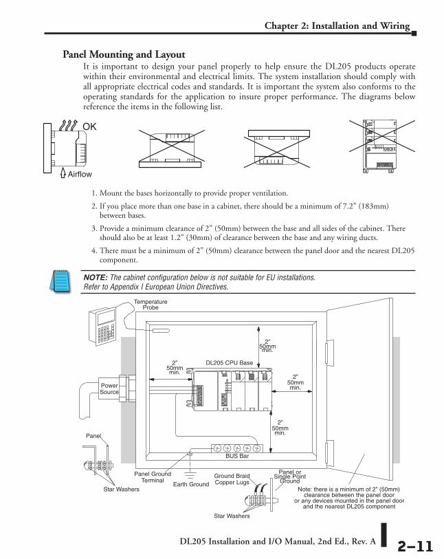
Panel Mounting and LayoutIt is important to design your panel properly to help ensure the DL205 products operate within their environmental and electrical limits. The system installation should comply with all appropriate electrical codes and standards. It is important the system also conforms to the operating standards for the application to insure proper performance. The diagrams below reference the items in the following list.
1. Mount the bases horizontally to provide proper ventilation.
2. If you place more than one base in a cabinet, there should be a minimum of 7.2” (183mm) between bases.
3. Provide a minimum clearance of 2” (50mm) between the base and all sides of the cabinet. There should also be at least 1.2” (30mm) of clearance between the base and any wiring ducts.
4. There must be a minimum of 2” (50mm) clearance between the panel door and the nearest DL205 component.
NOTE: The cabinet configuration below is not suitable for EU installations. Refer to Appendix I European Union Directives.
OK
Airflow
Safety G
uidelines
Earth Ground
Panel GroundTerminal
DL205 CPU Base
PowerSource
TemperatureProbe
Star Washers
Panel
Ground BraidCopper Lugs
Panel orSingle Point
Ground
Star Washers
BUS Bar
Note: there is a minimum of 2” (50mm)clearance between the panel door
or any devices mounted in the panel door
2”50mmmin.
2”50mmmin.
and the nearest DL205 component
2”50mmmin.
2”50mmmin.

DL205 Installation and I/O Manual, 2nd Ed., Rev. A 2–12
Chapter 2: Installation and Wiring
5. The ground terminal on the DL205 base must be connected to a single point ground. Use copper stranded wire to achieve a low impedance. Copper eye lugs should be crimped and soldered to the ends of the stranded wire to ensure good surface contact. Remove anodized finishes and use copper lugs and star washers at termination points. A general rule is to achieve a 0.1 ohm of DC resistance between the DL205 base and the single point ground.
6. There must be a single point ground (i.e. copper bus bar) for all devices in the panel requiring an earth ground return. The single point of ground must be connected to the panel ground termination. The panel ground termination must be connected to earth ground. For this connection you should use #12 AWG stranded copper wire as a minimum. Minimum wire sizes, color coding, and general safety practices should comply with appropriate electrical codes and standards for your region. A good common ground reference (Earth ground) is essential for proper operation of the DL205. There are several methods of providing an adequate common ground reference, including:
a) Installing a ground rod as close to the panel as possible.
b) Connection to incoming power system ground.
7. Properly evaluate any installations where the ambient temperature may approach the lower or upper limits of the specifications. Place a temperature probe in the panel, close the door and operate the system until the ambient temperature has stabilized. If the ambient temperature is not within the operating specification for the DL205 system, measures such as installing a cooling/heating source must be taken to get the ambient temperature within the DL205 operating specifications.
8. Device mounting bolts and ground braid termination bolts should be #10 copper bolts or equivalent. Tapped holes instead of nut–bolt arrangements should be used whenever possible. To ensure good contact on termination areas impediments such as paint, coating or corrosion should be removed in the area of contact.
9. The DL205 system is designed to be powered by 110/220 VAC, 24VDC, or 125VDC normally available throughout an industrial environment. Electrical power in some areas where the PLCs are installed is not always stable and storms can cause power surges. Due to this, powerline filters are recommended for protecting the DL205 PLCs from power surges and EMI/RFI noise. The Automation Powerline Filter, for use with 120VAC and 240VAC, 1–5 Amps, is an excellent choice (can be located at www.automationdirect.com), however, you can use a filter of your choice. These units install easily between the power source and the PLC.
EnclosuresSelection of a proper enclosure is important to ensure safe and proper operation of your DL205 system. Applications of DL205 systems vary and may require additional features. The minimum considerations for enclosures include:
• Conformance to electrical standards
• Protection from the elements in an industrial environment
• Common ground reference
• Maintenance of specified ambient temperature
• Access to equipment
• Security or restricted access
• Sufficient space for proper installation and maintenance of equipment

DL205 Installation and I/O Manual, 2nd Ed., Rev. A 2–13
Chapter 2: Installation and Wiring
Environmental SpecificationsThe following table lists the environmental specifications that generally apply to the DL205 system (CPU, Bases, I/O Modules). The ranges that vary for the Handheld Programmer are noted at the bottom of this chart. I/O module operation may fluctuate depending on the ambient temperature and your application. Please refer to the appropriate I/O module specifications for the temperature derating curves applying to specific modules.
PowerThe power source must be capable of supplying voltage and current complying with the base power supply specifications.
Specification AC Powered Bases 24 VDC Powered Bases 125 VDC Powered Bases
Part Numbers D2–03B–1 D2–04B–1 D2–06B–1 D2–09B–1
D2–03BDC1–1 D2–04BDC1–1 D2–06BDC1–1 D2–09BDC1–1
D2–06BDC2–1 D2–09BDC2–1
Input Voltage Range 100–240 VAC (+10%/ –15%) 50/60 Hz
10.2 – 28.8 VDC (24VDC) with less than 10% ripple
104–240 VDC +10% –15%
Maximum Inrush Current 30A 10A 20A
Maximum Power 80VA 25W 30W
Voltage Withstand (dielectric) 1 minute @ 1500VAC between primary, secondary, and field ground
Insulation Resistance > 10 MΩ at 500VDC
Auxiliary 24 VDC Output 20–28 VDC, less than 1V p-p 300mA max. None 20–28 VDC, less than 1V p-p
300mA max.Fusing* (internal to base power supply)
non–replaceable 2A @ 250V slow blow fuse
non–replaceable 3.15 A @ 250V slow blow fuse
non–replaceable 2A @ 250V slow blow fuse
Specification RatingStorage temperature –4° F to 158° F (–20° C to 70° C)
Ambient operating temperature* 32° F to 131° F (0° C to 55° C)
Ambient humidity** 30% – 95% relative humidity (non–condensing)
Vibration resistance MIL STD 810C, Method 514.2
Shock resistance MIL STD 810C, Method 516.2
Noise immunity NEMA (ICS3–304)
Atmosphere No corrosive gases* Operating temperature for the Handheld Programmer and the DV-1000 is 32° to 122° F (0° to 50° C) Storage
temperature for the Handheld Programmer and the DV-1000 is - 4° to 158° F (- 20° to 70° C).** Equipment will operate below 30% humidity. However, static electricity problems occur much more frequently at
lower humidity levels. Make sure you take adequate precautions when you touch the equipment. Consider using ground straps, anti-static floor coverings, etc., if you use the equipment in low humidity environments.
* External fusing is not beneficial. The internal fuse does not protect the power supply from overload. It provides protection from fire in case the power supply fails, so if the internal fuse blows it means that the power supply has already failed.

DL205 Installation and I/O Manual, 2nd Ed., Rev. A 2–14
Chapter 2: Installation and Wiring
Marine UseAmerican Bureau of Shipping (ABS) certification requires flame-retarding insulation as per 4-8-3/5.3.6(a). ABS will accept Navy low smoke cables, cable qualified to NEC “Plenum rated” (fire resistant level 4), or other similar flammability resistant rated cables. Use cable specifications for your system that meet a recognized flame retardant standard (i.e. UL, IEEE, etc.), including evidence of cable test certification (i.e. tests certificate, UL file number, etc.).
NOTE: Wiring needs to be “low smoke” per the above paragraph. Teflon coated wire is also recommended.
Agency Approvals Some applications require agency approvals. Typical agency approvals which your application may require are:
• UL (Underwriters’ Laboratories, Inc.) • CSA (Canadian Standards Association) • FM (Factory Mutual Research Corporation) • CUL (Canadian Underwriters’ Laboratories, Inc.)
24VDC Power BasesFollow these additional installation guidelines when installing D2-03BDC1-1, D2-04BDC1-1, D2-06BDC1-1 and D2-09BDC1-1 bases:
• Install these bases in compliance with the enclosure, mounting, spacing, and segregation requirements of the ultimate application.
• These bases must be used within their marked ratings.
• These bases are intended to be installed within an enclosure rated at least IP54.
• provisions should be made to prevent the rated voltage being exceeded by transient disturbances of more than 40%.

DL205 Installation and I/O Manual, 2nd Ed., Rev. A 2–15
Chapter 2: Installation and Wiring
Installing DL205 BasesChoosing the Base Type
The DL205 system offers four different sizes of bases and three different power supply options.
The following diagram shows an example of a 6-slot base.
Your choice of base depends on three things:
• Number of I/O modules required
• Input power requirement (AC or DC power)
• Available power budget
Mounting the BaseAll I/O configurations of the DL205 may use any of the base configurations. The bases are secured to the equipment panel or mounting location using four M4 screws in the corner tabs of the base. The full mounting dimensions are given in the previous section on Mounting Guidelines.
WARNING: To minimize the risk of electrical shock, personal injury, or equipment damage, always disconnect the system power before installing or removing any system component.
Power WiringConnections
CPU Slot I/O Slots
Mounting Tabs

DL205 Installation and I/O Manual, 2nd Ed., Rev. A 2–16
Chapter 2: Installation and Wiring
Using Mounting RailsThe DL205 bases can also be secured to the cabinet by using mounting rails. You should use rails that conform to DIN EN standard 50 022. Refer to our catalog for a complete line of DIN rail, DINnectors and DIN rail mounted apparatus. These rails are approximately 35mm high, with a depth of 7.5mm. If you mount the base on a rail, you should also consider using end brackets on each end of the rail. The end brackets help keep the base from sliding horizontally along the rail. This helps minimize the possibility of accidentally pulling the wiring loose.
If you examine the bottom of the base, you’ll notice small retaining clips. To secure the base to a DIN rail, place the base onto the rail and gently push up on the retaining clips. The clips lock the base onto the rail.
To remove the base, pull down on the retaining clips, lift up on the base slightly, and pull it away from the rail.
35 mm
7.5mm
Retaining Clips
DIN Rail Dimensions

DL205 Installation and I/O Manual, 2nd Ed., Rev. A 2–17
Chapter 2: Installation and Wiring
Installing Components in the BaseTo insert components into the base: first slide the module retaining clips to the out position and align the PC board(s) of the module with the grooves on the top and bottom of the base. Push the module straight into the base until it is firmly seated in the backplane connector. Once the module is inserted into the base, push in the retaining clips to firmly secure the module to the base.
WARNING: Minimize the risk of electrical shock, personal injury, or equipment damage. Always disconnect the system power before installing or removing any system component.
Align module PC board toslots in base and slide in
Push the retainingclips in to secure the module
to the DL205 base
CPU must be positioned inthe first slot of the base

DL205 Installation and I/O Manual, 2nd Ed., Rev. A 2–18
Chapter 2: Installation and Wiring
Base Wiring GuidelinesBase Wiring
The diagrams show the terminal connections located on the power supply of the DL205 bases. The base terminals can accept up to 16 AWG. You may be able to use larger wiring depending on the type of wire used, but 16 AWG is the recommended size. Do not overtighten the connector screws; the recommended torque value is 7.81 lb-in (0.882 N•m).
NOTE: You can connect either a 115 VAC or 220 VAC supply to the AC terminals. Special wiring or jumpers are not required as with some of the other DirectLOGIC products.
WARNING: Once the power wiring is connected, install the plastic protective cover. When the cover is removed, there is a risk of electrical shock if you accidentally touch the wiring or wiring terminals.
125 VDC Base Terminal Strip12/24 VDC Base Terminal Strip
G
12 – 24 VDC+
–115 – 264 VDC
G
24 VDC OUT, 0.3A–
+
–
+
110/220 VAC Base Terminal Strip
85 – 264 VAC
G
24 VDC OUT, 0.3A
LG
+

I/O WIrIng and SpecIfIcatIOnS 333
ChapterChapterChapter
In This Chapter...I/O Wiring Strategies ................................................................................................3–2
I/O Modules Position, Wiring, and Specification ...................................................3–13
Calculating the Power Budget ................................................................................3–18
DL205 Digital Input Modules ..................................................................................3–22
DL205 Digital Output Modules ...............................................................................3–28
DL205 Analog Input Modules .................................................................................3–44
DL205 RTD and Thermocouple Modules ................................................................3–52
DL205 Analog Output Modules ..............................................................................3–56
DL205 Combination Analog I/O Modules ..............................................................3–72
Glossary of Specification Terms .............................................................................3–78

DL205 Installation and I/O Manual, 2nd Ed., Rev. A 3–2
Chapter 3: I/O Wiring and Specifications
I/O Wiring StrategiesThe DL205 PLC system is very flexible and will work in many different wiring configurations. By studying this section before actual installation, you can probably find the best wiring strategy for your application. This will help to lower system cost, wiring errors, and avoid safety problems.
PLC Isolation BoundariesPLC circuitry is divided into three main regions separated by isolation boundaries, shown in the drawing below. Electrical isolation provides safety, so that a fault in one area does not damage another. A powerline filter will provide isolation between the power source and the power supply. A transformer in the power supply provides magnetic isolation between the primary and secondary sides. Opto-couplers provide optical isolation in Input and Output circuits. This isolates logic circuitry from the field side, where factory machinery connects. Note the discrete inputs are isolated from the discrete outputs, because each is isolated from the logic side. Isolation boundaries protect the operator interface (and the operator) from power input faults or field wiring faults. When wiring a PLC, it is extremely important to avoid making external connections that connect logic side circuits to any other.
In addition to the basic circuits covered above, AC-powered and 125VDC bases include an auxiliary +24VDC power supply with its own isolation boundary. Since the supply output is isolated from the other three circuits, it can power input and/or output circuits!
Safety G
uidelines
Input Module
CPU
Comm.
MainPowerSupply
Auxiliary+24VDCSupply
To ProgrammingDevice, Operator
Inputs Commons CommonsOutputs
+24VDC Out
PLCDL205
Interface, Network
Output Module
InternalBackplane
Supply forOutput Circuit
Primary Side Secondary, orLogic side
Field Side
FilterPowerInput
CPU
InputModuleMain
PowerSupply
Inputs
Outputs
PowerInput
OutputModule
Primary Side Secondary, orLogic side
Field Side
PLC
Programming Device,Operator Interface, or Network
IsolationBoundary
IsolationBoundary
(backplane)
(backplane)Filter

DL205 Installation and I/O Manual, 2nd Ed., Rev. A 3–3
Chapter 3: I/O Wiring and Specifications
Powering I/O Circuits with the Auxiliary SupplyIn some cases, using the built-in auxiliary +24VDC supply can result in a cost savings for your control system. It can power combined loads up to 300mA. Be careful not to exceed the current rating of the supply. If you are the system designer for your application, you may be able to select and design in field devices which can use the +24VDC auxiliary supply.
All AC powered and 125VDC DL205 bases feature the internal auxiliary supply. If input devices AND output loads need +24VDC power, the auxiliary supply may be able to power both circuits as shown in the following diagram.
The 12/24VDC powered DL205 bases are designed for application environments in which low-voltage DC power is more readily available than AC. These include a wide range of battery–powered applications, such as remotely-located control, in vehicles, portable machines, etc. For this application type, all input devices and output loads typically use the same DC power source. Typical wiring for DC-powered applications is shown in the following diagram.
Input ModuleAuxiliary+24VDCSupply
Power Input DL205 PLC
Output Module
Loads
AC Power or 125VDC Bases
+ –
Inputs Com. Outputs Com.
Input ModulePower Input
DL205 PLC
Output Module
Loads
DC Power+
–
+
–
Inputs Com. Outputs Com.

DL205 Installation and I/O Manual, 2nd Ed., Rev. A 3–4
Chapter 3: I/O Wiring and Specifications
Powering I/O Circuits Using Separate SuppliesIn most applications it will be necessary to power the input devices from one power source, and to power output loads from another source. Loads often require high-energy AC power, while input sensors use low-energy DC. If a machine operator is likely to come in close contact with input wiring, then safety reasons also require isolation from high-energy output circuits. It is most convenient if the loads can use the same power source as the PLC, and the input sensors can use the auxiliary supply, as shown to the left in the figure below.
If the loads cannot be powered from the PLC supply, then a separate supply must be used as shown to the right in the figure below.
Some applications will use the PLC external power source to also power the input circuit. This typically occurs on DC-powered PLCs, as shown in the drawing below to the left. The inputs share the PLC power source supply, while the outputs have their own separate supply. A worst-case scenario, from a cost and complexity viewpoint, is an application which requires separate power sources for the PLC, input devices, and output loads. The wiring diagram example below on the right shows how this can work, but the auxiliary supply output is an unused resource. You will want to avoid this situation, if possible.
Input ModuleAuxiliary+24VDCSupply
Power Input DL205 PLC
Output Module
Loads
AC Power
+ –
Inputs Com. Outputs Com.
Input ModuleAuxiliary+24VDCSupply
Power Input DL205 PLC
Output Module
Loads
AC Power
+ –
Inputs Com. Outputs Com.
LoadSupply
Input ModulePower Input
DL205 PLC
Output Module
Loads
DC Power+
–
+
–
Inputs Com. Outputs Com.
LoadSupply
Input ModuleAuxiliary+24VDCSupply
Power Input DL205 PLC
Output Module
Loads
AC Power
+ –
Inputs Com. Outputs Com.
LoadSupply
InputSupply

DL205 Installation and I/O Manual, 2nd Ed., Rev. A 3–5
Chapter 3: I/O Wiring and Specifications
Sinking / Sourcing ConceptsBefore going further in the study of wiring strategies, you must have a solid understanding of “sinking” and “sourcing” concepts. Use of these terms occurs frequently in input or output circuit discussions. It is the goal of this section to make these concepts easy to understand, further ensuring your success in installation. First the following short definitions are provided, followed by practical applications.
Sinking = provides a path to supply ground (–)
Sourcing = provides a path to supply source (+)
First you will notice these are only associated with DC circuits and not AC, because of the reference to (+) and (–) polarities. Therefore, sinking and sourcing terminology only applies to DC input and output circuits. Input and output points that are sinking only or sourcing only can conduct current in only one direction. This means it is possible to connect the external supply and field device to the I/O point with current trying to flow in the wrong direction, and the circuit will not operate. However, you can successfully connect the supply and field device every time by understanding “sourcing” and “sinking”.
For example, the figure to the right depicts a “sinking” input. To properly connect the external supply, you will have to connect it so the input provides a path to ground (–). Start at the PLC input terminal, follow through the input sensing circuit, exit at the common terminal, and connect the supply (–) to the common terminal. By adding the switch, between the supply (+) and the input, the circuit has been completed . Current flows in the direction of the arrow when the switch is closed.
Apply the circuit principle above to the four possible combinations of input/output sinking/sourcing types as shown below. The I/O module specifications at the end of this chapter list the input or output type.
+
–
InputSensing
PLCInput
Common
(sinking)
+
–
InputSensing
Load
Sinking Input Sinking Output
Sourcing Input Sourcing Output
PLCInput
Common
+
–
OutputSwitch
PLCOutput
Common
+
–
InputSensing
Load
PLC
Input
Common
+
–
OutputSwitch
PLC
Output
Common

DL205 Installation and I/O Manual, 2nd Ed., Rev. A 3–6
Chapter 3: I/O Wiring and Specifications
I/O “Common” Terminal ConceptsIn order for a PLC I/O circuit to operate, current must enter at one terminal and exit at another. Therefore, at least two terminals are associated with every I/O point. In the figure to the right, the Input or Output terminal is the main path for the current. One additional terminal must provide the return path to the power supply.
If there was unlimited space and budget for I/O terminals, every I/O point could have two dedicated terminals as the figure above shows. However, providing this level of flexibility is not practical or even necessary for most applications. So, most Input or Output points on PLCs are in groups which share the return path (called commons). The figure to the right shows a group (or bank) of four input points which share a common return path. In this way, the four inputs require only five terminals instead of eight.
NOTE: In the circuit above, the current in the common path is 4 times any channel’s input current when all inputs are energized. This is especially important in output circuits, where heavier gauge wire is sometimes necessary on commons.
Most DL205 input and output modules group their I/O points into banks that share a common return path. The best indication of I/O common grouping is on the wiring label, such as the one shown to the right. There are two circuit banks with eight input points in each. The common terminal for each is labeled “CA” and “CB”, respectively.
In the wiring label example, the positive terminal of a DC supply connects to the common terminals. Some symbols you will see on the wiring labels, and their meanings are:
L
AC supply AC or DC supply
Input Switch Output Load
DC supply
+–
+
–
I/OCircuit
PLC
(I/O Point)
Return Path
FieldDevice
Main Path
+
–
InputSensing
PLC
Input 4
Common
Input 3
Input 2
Input 1
A
B
20-28VDC8mACLASS 2
D2-16ND3-2
IN 24
D2–16ND3–2
VDC 0 1 23
4 5 6 7
CA4567
CB456
3210
NC3210
7
DL205 Installation and I/O Manual, 2nd Ed., Rev. A 3–7
Chapter 3: I/O Wiring and Specifications
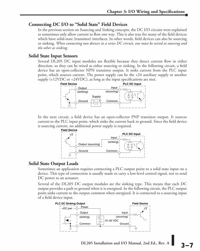
Connecting DC I/O to “Solid State” Field DevicesIn the previous section on Sourcing and Sinking concepts, the DC I/O circuits were explained to sometimes only allow current to flow one way. This is also true for many of the field devices which have solid-state (transistor) interfaces. In other words, field devices can also be sourcing or sinking. When connecting two devices in a series DC circuit, one must be wired as sourcing and the other as sinking.
Solid State Input SensorsSeveral DL205 DC input modules are flexible because they detect current flow in either direction, so they can be wired as either sourcing or sinking. In the following circuit, a field device has an open-collector NPN transistor output. It sinks current from the PLC input point, which sources current. The power supply can be the +24 auxiliary supply or another supply (+12VDC or +24VDC), as long as the input specifications are met.
In the next circuit, a field device has an open-collector PNP transistor output. It sources current to the PLC input point, which sinks the current back to ground. Since the field device is sourcing current, no additional power supply is required.
Solid State Output LoadsSometimes an application requires connecting a PLC output point to a solid state input on a device. This type of connection is usually made to carry a low-level control signal, not to send DC power to an actuator.
Several of the DL205 DC output modules are the sinking type. This means that each DC output provides a path to ground when it is energized. In the following circuit, the PLC output point sinks current to the output common when energized. It is connected to a sourcing input of a field device input.
Field Device
+–
PLC DC Input
Output
Ground
Input
Common
Supply
(sinking) (sourcing)
Field DevicePLC DC Input
Output (sourcing)
Ground
Input
Common
+V
(sinking)
Field Device
Output
Ground
Input
Common
+V
PLC DC Sinking Output
+DC pwr
+
–
(sourcing)(sinking)
Power
10–30 VDC
DL205 Installation and I/O Manual, 2nd Ed., Rev. A 3–8
Chapter 3: I/O Wiring and Specifications
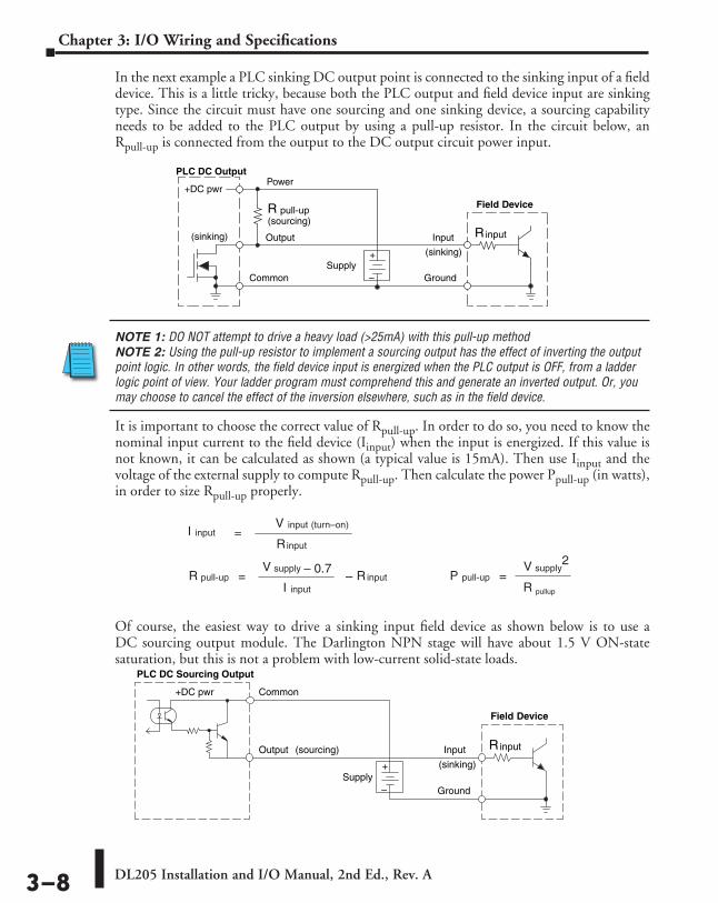
In the next example a PLC sinking DC output point is connected to the sinking input of a field device. This is a little tricky, because both the PLC output and field device input are sinking type. Since the circuit must have one sourcing and one sinking device, a sourcing capability needs to be added to the PLC output by using a pull-up resistor. In the circuit below, an Rpull-up is connected from the output to the DC output circuit power input.
NOTE 1: DO NOT attempt to drive a heavy load (>25mA) with this pull-up method NOTE 2: Using the pull-up resistor to implement a sourcing output has the effect of inverting the output point logic. In other words, the field device input is energized when the PLC output is OFF, from a ladder logic point of view. Your ladder program must comprehend this and generate an inverted output. Or, you may choose to cancel the effect of the inversion elsewhere, such as in the field device.
It is important to choose the correct value of Rpull-up. In order to do so, you need to know the nominal input current to the field device (Iinput) when the input is energized. If this value is not known, it can be calculated as shown (a typical value is 15mA). Then use Iinput and the voltage of the external supply to compute Rpull-up. Then calculate the power Ppull-up (in watts), in order to size Rpull-up properly.
Of course, the easiest way to drive a sinking input field device as shown below is to use a DC sourcing output module. The Darlington NPN stage will have about 1.5 V ON-state saturation, but this is not a problem with low-current solid-state loads.
Field Device
Output
Ground
Input
Common
PLC DC Sourcing Output
+DC pwr
+
–
(sourcing)
(sinking)Supply
inputR
Field Device
Output
Ground
Input
Common
PLC DC Output
+DC pwr
+
–
(sourcing)
(sinking)
Power
(sinking)
pull-up
Supply
R
inputR
pull-upR inputR=supplyV – 0.7
–inputI
inputI =input (turn–on)V
inputR
pull-upP =supplyV 2
pullupR

DL205 Installation and I/O Manual, 2nd Ed., Rev. A 3–9
Chapter 3: I/O Wiring and Specifications
Relay Output GuidelinesSeveral output modules in the DL205 I/O family feature relay outputs: D2–04TRS, D2–08TR, D2–12TR, D2–08CDR, F2–08TR and F2–08TRS. Relays are best for the following applications:
• Loads that require higher currents than the solid-state outputs can deliver
• Cost-sensitive applications
• Some output channels need isolation from other outputs (such as when some loads require different voltages than other loads)
Some applications in which NOT to use relays:
• Loads that require currents under 10mA
• Loads which must be switched at high speed or heavy duty cycle
Relay outputs in the DL205 output modules are available in two contact arrangements, shown to the right. The Form A type, or SPST (single pole, single throw) type is normally open and is the simplest to use. The Form C type, or SPDT (single pole, double throw) type has a center contact which moves and a stationary contact on either side. This provides a normally closed contact and a normally open contact.
Some relay output modules relays share common terminals, which connect to the wiper contact in each relay of the bank. Other relay modules have relays which are completely isolated from each other. In all cases, the module drives the relay coil when the corresponding output point is on.
Surge Suppression For Inductive Loads
NOTE: For updated information on surge suppression for inductive loads, refer to Application Note AN-MISC-032 located on the Technical Support area of our website. The url is: http://support.automationdirect.com/docs/an-misc-032.pdf
Inductive load devices (devices with a coil) generate transient voltages when de-energized with a relay contact. When a relay contact is closed it, “bounces”, which energizes and de-energizes the coil until the “bouncing” stops. The transient voltages generated are much larger in amplitude than the supply voltage, especially with a DC supply voltage.
When switching a DC-supplied inductive load, the full supply voltage is always present when the relay contact opens (or “bounces”). When switching an AC-supplied inductive load, there are two (2) points when the voltage is zero (0) in one complete cycle of a sine wave; therefore, there are two (2) chances in 60 (60Hz) or 50 (50Hz) to stop the current flow at a zero crossover point. If current flow isn’t stopped, the relay contact will open (or “bounce”). If the voltage is not zero when the relay contact opens, there is energy stored in the inductor that is released when the voltage to the inductor is suddenly removed. This release of energy is the cause of the transient voltages.
Relay with Form A contacts
Relay with Form C contacts
DL205 Installation and I/O Manual, 2nd Ed., Rev. A 3–10
Chapter 3: I/O Wiring and Specifications
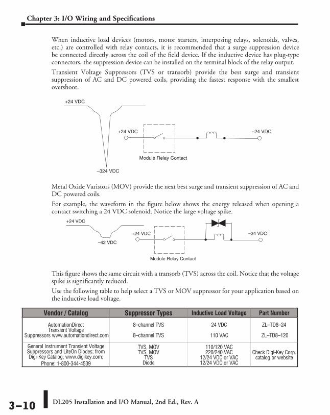
When inductive load devices (motors, motor starters, interposing relays, solenoids, valves, etc.) are controlled with relay contacts, it is recommended that a surge suppression device be connected directly across the coil of the field device. If the inductive device has plug-type connectors, the suppression device can be installed on the terminal block of the relay output.
Transient Voltage Suppressors (TVS or transorb) provide the best surge and transient suppression of AC and DC powered coils, providing the fastest response with the smallest overshoot.
Metal Oxide Varistors (MOV) provide the next best surge and transient suppression of AC and DC powered coils.
For example, the waveform in the figure below shows the energy released when opening a contact switching a 24 VDC solenoid. Notice the large voltage spike.
This figure shows the same circuit with a transorb (TVS) across the coil. Notice that the voltage spike is significantly reduced.
Use the following table to help select a TVS or MOV suppressor for your application based on the inductive load voltage.
+24 VDC –24 VDC
Module Relay Contact
–324 VDC
+24 VDC
+24 VDC –24 VDC
Module Relay Contact
–42 VDC
+24 VDC
Vendor / Catalog Suppressor Types Inductive Load Voltage Part Number
AutomationDirect Transient Voltage
Suppressors www.automationdirect.com
8–channel TVS
8–channel TVS
24 VDC
110 VAC
ZL–TD8–24
ZL–TD8–120
General Instrument Transient Voltage Suppressors and LiteOn Diodes; from Digi-Key Catalog; www.digikey.com;
Phone: 1-800-344-4539
TVS, MOV TVS, MOV
TVS Diode
110/120 VAC 220/240 VAC
12/24 VDC or VAC 12/24 VDC or VAC
Check Digi-Key Corp. catalog or website
DL205 Installation and I/O Manual, 2nd Ed., Rev. A 3–11
Chapter 3: I/O Wiring and Specifications
Relay contacts wear according to the amount of relay switching, amount of spark created at the time of open or closure, and presence of airborne contaminants.
However, there are some steps you can take to help prolong the life of relay contacts:
• Switch the relay on or off only when the application requires it.
• I f you have the option, switch the load on or off at a time when it will draw the least current.
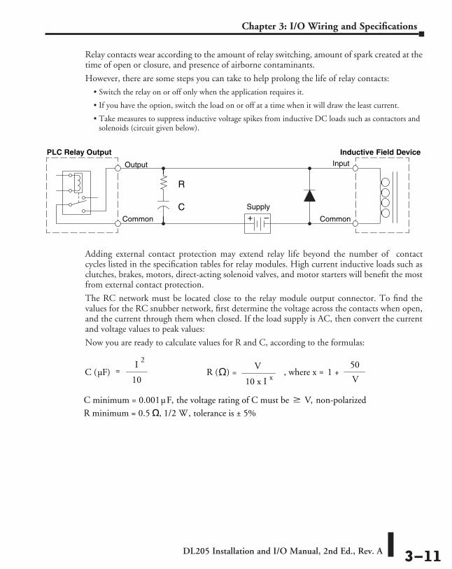
• Take measures to suppress inductive voltage spikes from inductive DC loads such as contactors and solenoids (circuit given below).
Adding external contact protection may extend relay life beyond the number of contact cycles listed in the specification tables for relay modules. High current inductive loads such as clutches, brakes, motors, direct-acting solenoid valves, and motor starters will benefit the most from external contact protection.
The RC network must be located close to the relay module output connector. To find the values for the RC snubber network, first determine the voltage across the contacts when open, and the current through them when closed. If the load supply is AC, then convert the current and voltage values to peak values:
Now you are ready to calculate values for R and C, according to the formulas:
R ( ) =C (µF) =10
I2
V
10 x I x, where x
50
V1 +
C minimum = 0.001 µF, the voltage rating of C must be V, non-polarizedR minimum = 0.5 , 1/2 W, tolerance is ± 5%
=
Inductive Field Device
+ –
PLC Relay Output
Output
Common
Input
Common
Supply
R
C

DL205 Installation and I/O Manual, 2nd Ed., Rev. A 3–12
Chapter 3: I/O Wiring and Specifications
For example, suppose a relay contact drives a load at 120VAC, 1/2 A. Since this example has an AC power source, first calculate the peak values:
Now, find the values of R and C:
If the contact is switching a DC inductive load, add a diode across the load as near to load coil as possible. When the load is energized, the diode is reverse-biased (high impedance). When the load is turned off, energy stored in its coil is released in the form of a negative-going voltage spike. At this moment, the diode is forward-biased (low impedance) and shunts the energy to ground. This protects the relay contacts from the high voltage arc that would occur as the contacts are opening.
For best results, follow these guidelines in using a noise suppression diode:
• DO NOT use this circuit with an AC power supply.
• Place the diode as close to the inductive field device as possible.
• Use a diode with a peak inverse voltage rating (PIV) at least 100 PIV, 3A forward current or larger. Use a fast-recovery type (such as Schottky type). DO NOT use a small-signal diode such as 1N914, 1N941, etc.
• Be sure the diode is in the circuit correctly before operation. If installed backwards, it short-circuits the supply when the relay energizes.
Ipeak = Irms x 1.414, = 0.5 x 1.414 = 0.707 Amperes
Vpeak = Vrms x 1.414 = 120 x 1.414 = 169.7 Volts
R () =
C (µ F) =10
I 2
V
10 x I x, where x=
50
V1 +
=10
0.707 2
= 0.05 µ F, voltage rating 170 Volts
x=50
169.71 + = 1.29 R ( ) =
169.7
10 x 0.707 1.29= 26 , 1/2 W, ± 5%

DL205 Installation and I/O Manual, 2nd Ed., Rev. A 3–13
Chapter 3: I/O Wiring and Specifications
I/O Modules Position, Wiring, and SpecificationSlot Numbering
The DL205 bases each provide different numbers of slots for use with the I/O modules. You may notice the bases refer to 3-slot, 4-slot, etc. One of the slots is dedicated to the CPU-slot controller, so you always have one less I/O slot. For example, there are five I/O slots with a 6-slot base. The I/O slots are numbered 0–4. The CPU slot always contains a PLC CPU or a CPU–slot controller and is not numbered.
Module Placement RestrictionsThe following table lists the valid locations for all types of modules in a DL205 system.
Module/Unit Local CPU Base Local Expansion Base Remote I/O Base
CPUs CPU Slot Only
DC Input Modules A A A
AC Input Modules A A A
DC Output Modules A A A
AC Output Modules A A A
Relay Output Modules A A A
Analog Input and Output Modules A A A
Local Expansion Base Expansion Module A A
Base Controller Module CPU Slot Only
Serial Remote I/O Remote Master A
Remote Slave Unit CPU Slot Only
Ethernet Remote Master A
CPU Interface Ethernet Base Controller Slot 0 Only Slot 0 Only*
WinPLC Slot 0 Only
DeviceNet Slot 0 Only
Profibus Slot 0 Only
SDS Slot 0 Only
Specialty Modules Counter Interface Slot 0 Only
Counter I/O A A* Data Communications A
Ethernet Communications A
BASIC CoProcessor A
Simulator A A A
Filler A A A
* When used with H2-ERM Ethernet Remote I/O system
CPU Slot I/O Slots
Slot 0 Slot 1 Slot 2 Slot 3 Slot 4
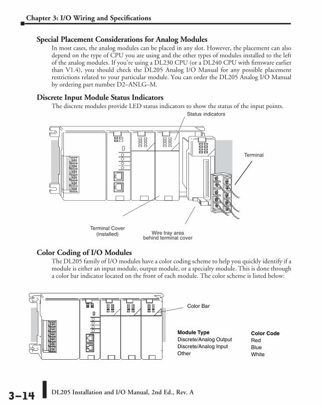
DL205 Installation and I/O Manual, 2nd Ed., Rev. A 3–14
Chapter 3: I/O Wiring and Specifications
Special Placement Considerations for Analog Modules In most cases, the analog modules can be placed in any slot. However, the placement can also depend on the type of CPU you are using and the other types of modules installed to the left of the analog modules. If you’re using a DL230 CPU (or a DL240 CPU with firmware earlier than V1.4), you should check the DL205 Analog I/O Manual for any possible placement restrictions related to your particular module. You can order the DL205 Analog I/O Manual by ordering part number D2–ANLG–M.
Discrete Input Module Status IndicatorsThe discrete modules provide LED status indicators to show the status of the input points.
Color Coding of I/O ModulesThe DL205 family of I/O modules have a color coding scheme to help you quickly identify if a module is either an input module, output module, or a specialty module. This is done through a color bar indicator located on the front of each module. The color scheme is listed below:
Wire tray area
Status indicators
Terminal Cover(installed)
behind terminal cover
Terminal
Module TypeDiscrete/Analog OutputDiscrete/Analog InputOther
Color CodeRedBlueWhite
Color Bar

DL205 Installation and I/O Manual, 2nd Ed., Rev. A 3–15
Chapter 3: I/O Wiring and Specifications
Wiring the Different Module ConnectorsThere are two types of module connectors for the DL205 I/O. Some modules have normal screw terminal connectors. Other modules have connectors with recessed screws. The recessed screws help minimize the risk of someone accidentally touching active wiring.
Both types of connectors can be easily removed. If you examine the connectors closely, you’ll notice there are squeeze tabs on the top and bottom. To remove the terminal block, press the squeeze tabs and pull the terminal block away from the module.
We also have DIN rail mounted terminal blocks, DINnectors (refer to our catalog for a complete listing of all available products). ZIPLinks come with special pre–assembled cables with the I/O connectors installed and wired.
WARNING: For some modules, field device power may still be present on the terminal block even though the PLC system is turned off. To minimize the risk of electrical shock, check all field device power before you remove the connector.

DL205 Installation and I/O Manual, 2nd Ed., Rev. A 3–16
Chapter 3: I/O Wiring and Specifications
I/O Wiring ChecklistUse the following guidelines when wiring the I/O modules in your system.
1. There is a limit to the size of wire the modules can accept. The table below lists the suggested AWG for each module type. When making terminal connections, follow the suggested torque values.
*NOTE: 16 AWG Type TFFN or Type MTW is recommended. Other types of 16 AWG may be acceptable, but it really depends on the thickness and stiffness of the wire insulation. If the insulation is too thick or stiff and a majority of the module’s I/O points are used, then the plastic terminal cover may not close properly or the connector may pull away from the module. This applies especially for high temperature thermoplastics such as THHN.
2. Always use a continuous length of wire; do not combine wires to attain a needed length.
3. Use the shortest possible wire length.
4. Use wire trays for routing where possible.
5. Avoid running wires near high energy wiring. Also, avoid running input wiring close to output wiring where possible.
6. To minimize voltage drops when wires must run a long distance, consider using multiple wires for the return line.
7. Avoid running DC wiring in close proximity to AC wiring where possible.
8. Avoid creating sharp bends in the wires.
9. To reduce the risk of having a module with a blown fuse, we suggest you add external fuses to your I/O wiring. A fast blow fuse, with a lower current rating than the I/O module fuse, can be added to each common or, a fuse with a rating of slightly less than the maximum current per output point can be added to each output. Refer to our catalog for a complete line of DINnectors, DIN rail mounted fuse blocks.
NOTE: For modules which have soldered or non-replaceable fuses, we recommend you return your module to us and let us replace your blown fuse(s) since disassembling the module will void your warranty.
Safety G
uidelines
DINnector External Fuses(DIN rail mounted Fuses)
Terminal type Suggested AWG Range Suggested Torque10-Terminal Fixed 14 – 24 AWG 3.5 lb-inch (0.4 N·m)10-Terminal Removable 16* – 24 AWG 7.81 lb-inch (0.88 N·m)20-Terminal Removable 16* – 24 AWG 2.65 lb-in (0.3 N·m)

DL205 Installation and I/O Manual, 2nd Ed., Rev. A 3–17
Chapter 3: I/O Wiring and Specifications
I/O Points Required for Each ModuleEach type of module requires a certain number of I/O points. This is also true for some specialty modules, such as analog, counter interface, etc..
NOTE 1: –12pt. modules consume 16 points. The first 6 points are assigned, two are skipped, and then the next 6 points are assigned. For example, a D2–12TA installed in slot 0 would use Y0–Y5, and Y-10-Y15. Y6–Y7 and Y16–Y17 would be unused.
DC Input Modules Number of I/O Pts. Required Specialty Modules, etc. Number of I/O Pts. RequiredD2–08ND3 8 Input H2–ECOM(–F) NoneD2–16ND3–2 16 Input D2–DCM NoneD2–32ND3(–2) 32 Input H2–ERM(–F) NoneAC Input Modules H2–EBC(–F) NoneD2–08NA–1 8 Input D2–RMSM NoneD2–08NA–2 8 Input D2–RSSS NoneD2–16NA 16 Input F2–CP128 NoneDC Output Modules H2–CTRIO None
D2–04TD1 8 Output (Only the first four points are used) D2–CTRINT 8 Input 8 Output
D2–08TD1 8 Output F2–DEVNETS–1 NoneD2–16TD1–2 (2-2) 16 Output H2–PBC NoneD2–16TD1(2)P 16 Output F2–SDS–1 NoneD2–32TD1(–2) 32 Output D2–08SIM 8 InputAC Output Modules D2-EM NoneD2–08TA 8 Output D2-CM NoneF2–08TA 8 Output H2-ECOM(100) NoneD2–12TA 16 Output (See note 1)Relay Output Modules
D2–04TRS 8 Output (Only the first four points are used)
D2–08TR 8 OutputF2–08TRS 8 OutputF2–08TR 8 OutputD2–12TR 16 Output (See note 1)Combination Modules
D2–08CDR 8 In, 8 Out (Only the first four points are used for each type)
Analog ModulesF2–04AD–1 & 1L 16 InputF2–04AD–2 & 2L 16 InputF2–08AD–1 16 InputF2–02DA–1 & 1L 16 OutputF2–02DA–2 & 2L 16 OutputF2–08DA–1 16 OutputF2–08DA–2 16 OutputF2–02DAS–1 32 OutputF2–02DAS–2 32 OutputF2–4AD2DA 16 Input & 16 OutputF2–8AD4DA-1 32 Input & 32 OutputF2–8AD4DA-2 32 Input & 32 OutputF2–04RTD 32 InputF2–04THM 32 Input

DL205 Installation and I/O Manual, 2nd Ed., Rev. A 3–18
Chapter 3: I/O Wiring and Specifications
Calculating the Power BudgetManaging your Power Resource
When you determine the types and quantity of I/O modules you will be using in the DL205 system it is important to remember there is a limited amount of power available from the power supply. We have provided a chart to help you easily see the amount of power available with each base. The following chart will help you calculate the amount of power you need with your I/O selections. At the end of this section you will also find an example of power budgeting and a worksheet for your own calculations.
If the I/O you choose exceeds the maximum power available from the power supply, you may need to use local expansion bases or remote I/O bases.
WARNING: It is extremely important to calculate the power budget. If you exceed the power budget, the system may operate in an unpredictable manner which may result in a risk of personal injury or equipment damage.
CPU Power SpecificationsThe following chart shows the amount of current available for the two voltages supplied from the DL205 base. Use these currents when calculating the power budget for your system. The Auxiliary 24V Power Source mentioned in the table is a connection at the base terminal strip allowing you to connect to devices or DL205 modules that require 24VDC.
Module Power RequirementsUse the power requirements shown on the next page to calculate the power budget for your system. If an External 24VDC power supply is required, the external 24VDC from the base power supply may be used as long as the power budget is not exceeded.
Bases 5V Current Supplied Auxiliary 24VDC Current Supplied D2–03B–1 2600 mA 300 mA D2–04B–1 2600 mA 300 mA D2–06B–1 2600 mA 300 mA D2–09B–1 2600 mA 300 mA D2–03BDC1–1 2600 mA None D2–04BDC1–1 2600 mA None D2–06BDC1–1 2600 mA None D2–09BDC1–1 2600 mA None D2–06BDC2–1 2600 mA 300 mA D2–09BDC2–1 2600 mA 300 mA

DL205 Installation and I/O Manual, 2nd Ed., Rev. A 3–19
Chapter 3: I/O Wiring and Specifications
Power Consumed Power Consumed
Device 5V (mA) 24V Auxilliary (mA) Device 5V (mA) 24V Auxilliary
(mA)CPUs Combination ModulesD2–230 120 0 D2–08CDR 200 0D2–240 120 0 Specialty ModulesD2–250–1 330 0 H2–PBC 530 0D2–260/262 330 0 H2–ECOM 450 0DC Input Modules H2–ECOM100 300 0D2–08ND3 50 0 H2–ECOM-F 640 0D2–16ND3–2 100 0 H2–ERM 320 0D2–32ND3(–2) 25 0 H2–ERM–F 450 0AC Input Modules H2–EBC 320 0D2–08NA–1 50 0 H2–EBC–F 450 0 D2–08NA–2 100 0 H2–CTRIO 400 0D2–16NA 100 0 D2–DCM 300 0DC Output Modules D2–RMSM 200 0D2–04TD1 60 20 D2–RSSS 150 0 D2–08TD1(–2) 100 0 D2–CTRINT 50* 0D2–16TD1–2 200 80 D2–08SIM 50 0D2–16TD2–2 200 0 D2–CM 100 0D2–32TD1(–2) 350 0 D2–EM 130 0AC Output Modules F2–CP128 235 0D2–08TA 250 0 F2–DEVNETS–1 160 0F2–08TA 250 0 F2–SDS–1 160 0D2–12TA 350 0Relay Output ModulesD2–04TRS 250 0D2–08TR 250 0F2–08TRS 670 0F2–08TR 670 0D2–12TR 450 0Analog ModulesF2–04AD–1 50 80 F2–02DAS–1 100 50mA per channelF2–04AD–1L 100 5mA @ 10-30V F2–02DAS–2 100 60mA per channelF2–04AD–2 110 5mA @ 10-30V F2–4AD2DA 90 80mA**F2–04AD–2L 60 90mA @ 12V** F2–8AD4DA-1 35 100F2–08AD–1 100 5mA @ 10-30V F2–8AD4DA-2 35 80F2–08AD–2 100 5mA @ 10-30V F2–04RTD 90 0F2–02DA–1 40 60** F2–04THM 110 60F2–02DA–1L 40 70mA @ 12V**F2–02DA–2 40 60F2–02DA–2L 40 70mA @ 12V**F2–08DA–1 30 50mA**F2–08DA–2 60 140*requires external 5VDC for outputs**add an additional 20mA per loop
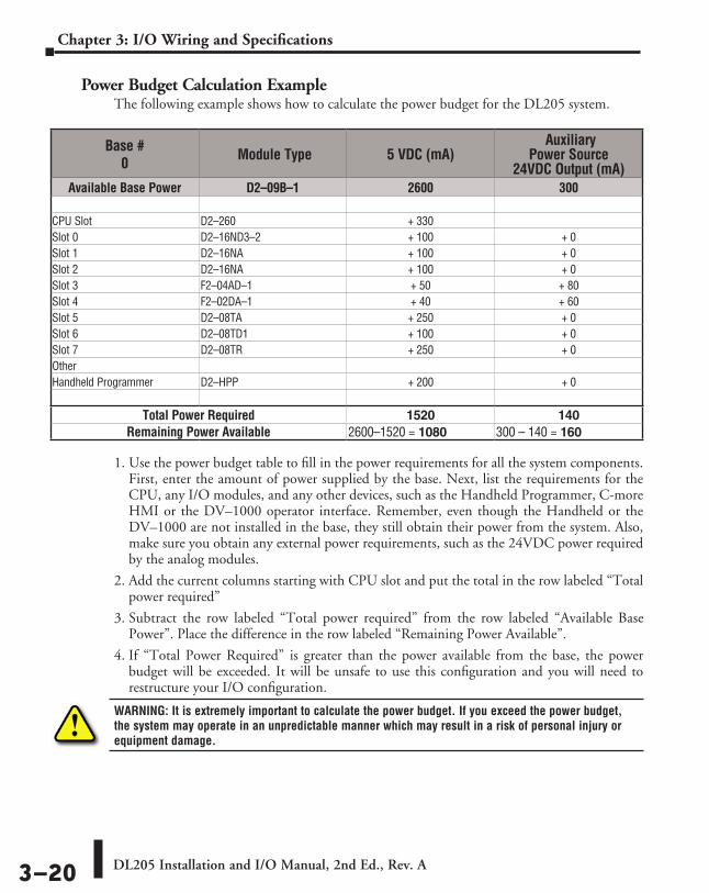
DL205 Installation and I/O Manual, 2nd Ed., Rev. A 3–20
Chapter 3: I/O Wiring and Specifications
Power Budget Calculation ExampleThe following example shows how to calculate the power budget for the DL205 system.
1. Use the power budget table to fill in the power requirements for all the system components. First, enter the amount of power supplied by the base. Next, list the requirements for the CPU, any I/O modules, and any other devices, such as the Handheld Programmer, C-more HMI or the DV–1000 operator interface. Remember, even though the Handheld or the DV–1000 are not installed in the base, they still obtain their power from the system. Also, make sure you obtain any external power requirements, such as the 24VDC power required by the analog modules.
2. Add the current columns starting with CPU slot and put the total in the row labeled “Total power required”
3. Subtract the row labeled “Total power required” from the row labeled “Available Base Power”. Place the difference in the row labeled “Remaining Power Available”.
4. If “Total Power Required” is greater than the power available from the base, the power budget will be exceeded. It will be unsafe to use this configuration and you will need to restructure your I/O configuration.
WARNING: It is extremely important to calculate the power budget. If you exceed the power budget, the system may operate in an unpredictable manner which may result in a risk of personal injury or equipment damage.
Base # 0 Module Type 5 VDC (mA)
Auxiliary Power Source
24VDC Output (mA)Available Base Power D2–09B–1 2600 300
CPU Slot D2–260 + 330Slot 0 D2–16ND3–2 + 100 + 0Slot 1 D2–16NA + 100 + 0Slot 2 D2–16NA + 100 + 0Slot 3 F2–04AD–1 + 50 + 80Slot 4 F2–02DA–1 + 40 + 60Slot 5 D2–08TA + 250 + 0Slot 6 D2–08TD1 + 100 + 0Slot 7 D2–08TR + 250 + 0OtherHandheld Programmer D2–HPP + 200 + 0
Total Power Required 1520 140Remaining Power Available 2600–1520 = 1080 300 – 140 = 160

DL205 Installation and I/O Manual, 2nd Ed., Rev. A 3–21
Chapter 3: I/O Wiring and Specifications
Power Budget Calculation WorksheetThis blank chart is provided for you to copy and use in your power budget calculations.
1. Use the power budget table to fill in the power requirements for all the system components. This includes the CPU, any I/O modules, and any other devices, such as the Handheld Programmer, C-more HMI or the DV–1000 operator interface. Also, make sure you obtain any external power requirements, such as the 24VDC power required by the analog modules.
2. Add the current columns starting with CPU slot and put the total in the row labeled “Total power required”.
3. Subtract the row labeled “Total power required” from the row labeled “Available Base Power”. Place the difference in the row labeled “Remaining Power Available”.
4. If “Total Power Required” is greater than the power available from the base, the power budget will be exceeded. It will be unsafe to use this configuration and you will need to restructure your I/O configuration.
WARNING: It is extremely important to calculate the power budget. If you exceed the power budget, the system may operate in an unpredictable manner which may result in a risk of personal injury or equipment damage.
Base # 0 Module Type 5VDC (mA)
Auxiliary Power Source
24VDC Output (mA)Available Base Power
CPU Slot Slot 0 Slot 1 Slot 2Slot 3 Slot 4 Slot 5 Slot 6 Slot 7Other
Total Power Required Remaining Power Available

DL205 Installation and I/O Manual, 2nd Ed., Rev. A 3–22
Chapter 3: I/O Wiring and Specifications
D2-08ND3, DC Input D2-16ND3-2, DC Input
OpticalCOM Isolator
INPUT
12--24VDC
V+
To LE D
Internal module circuitry
COM
CC
0
1
2
3
4
5
6
7
12--24VDC
Internallyconnected
0
2
4
6
8
0 10 20 30 40 50 55
Ambient Temperature (°C/°F )32 50 68 86 104 122131
C°F°
Derating ChartPoints
+
C
C
0
4
1
5
2
6
3
7
10.2--26.4VDC4--12mA
D2--08ND3
IN 12--24
D2--08ND3
VDC0123
4567
+
-
-
+ -
+-
Sink
Source
Sink
Source
A
B
20--28VDC8mA
IN 24
D2--16ND3--2
VDC0123
4567
CA
4
5
6
7
CB
4
5
63
2
1
0
NC
3
2
1
0
7
CLASS2
OpticalCOM Isolator
Derating Chart
INPUT
24 VDC
V+
To LE D
Internal module circuitry
0
1
2
3
5
6
7
NC
0
1
2
3
CB
4
5
6
7
CA
4
0
4
8
12
16Points
0 10 20 30 40 50 55
Ambient Temperature (°C/°F )32 50 68 86 104 122131
C°F°
+
+
+
+-
-
-
+-
+--Sink
Source24 VDC
Sink
Source
SinkSource24 VDC
Inputs per Module 8 (sink/source)
Commons per Module 1 (2 I/O terminal points)Input Voltage Range 10.2-26.4 VDCPeak Voltage 26.4 VDCON Voltage Level 9.5 VDC minimumOFF Voltage Level 3.5 VDC maximumAC Frequency N/A Input Impedance 2.7 kq
Input Current4.0 mA @ 12VDC8.5 mA @ 24VDC
Minimum ON Current 3.5 mAMaximum OFF Current 1.5 mABase Power Required 5VDC 50mA
OFF to ON Response 1 to 8 msON to OFF Response 1 to 8 msTerminal Type (included) Removable, D2-8IOCON
Status Indicator Logic side
Weight 2.3 oz. (65g)
Inputs per Module 16 (sink/source)
Commons per Module 2 isolated (8 I/O terminal points/com)
Input Voltage Range 20-28 VDCPeak Voltage 30VDC (10mA)ON Voltage Level 19VDC minimumOFF Voltage Level 7VDC maximumAC Frequency N/A Input Impedance 3.9 kq
Input Current 6mA @ 24VDCMinimum ON Current 3.5 mAMaximum OFF Current 1.5 mABase Power Required 5VDC 100mA
OFF to ON Response 3 to 9 msON to OFF Response 3 to 9 msTerminal Type (included) Removable, D2-16IOCON
Status Indicator Logic side
Weight 2.3 oz. (65g)
DL205 Digital Input Modules

DL205 Installation and I/O Manual, 2nd Ed., Rev. A 3–23
Chapter 3: I/O Wiring and Specifications
D2–32ND3, DC Input
OpticalCOM Isolator
INPUT
24 VDC
V+
To Logic
Internal module circuitry
+
IN 24
D2--32ND3
VDCACT
22--26VDC4--6mACLAS S 2
A0A1A2A3
A4A5A6A7
C0C1C2C3
C4C5C6C7
B0B1B2B3
B4B5
B7B6
D0D1D2D3
D4D5D6D7
CI CI
CII CII
CIII
CIV
CIII
CIV
A4A0
A5A1
A6A2
A7A3
COM I
B4B0
B5B1
B6B2
B7B3
COM II
C4C0
C5C1
C6C2
C7C3
COM III
D4D0
D5D1
D6D2
D7D3
COM IV
0
16
32Points
0 10 20 30 40 50 55
Ambient Temperature (°C/°F )32 50 68 86 104 122131
C°F°
Derating Chart
24VDC
+
-
+-
-
+
-
24VDC +
-
+
-
+
-
+
-
24VDC
+
-
+
-
24VDC
Sink
Source
Sink
Source
Sink
Source
Sink
Source
Sink
Source
Inputs per Module 32 (sink/source)
Commons per Module 4 isolated (8 I/O terminal points / com)Input Voltage Range 20-28 VDCPeak Voltage 30VDCON Voltage Level 19VDC minimumOFF Voltage Level 7VDC maximumAC Frequency N/A Input Impedance 4.8 kq
Input Current 8.0 mA @ 24 VDCMinimum ON Current 3.5 mAMaximum OFF Current 1.5 mABase Power Required 5VDC 25mA OFF to ON Response 3 to 9 msON to OFF Response 3 to 9 msTerminal Type (not included) Removable 40-pin Connector1
Status Indicator Module Activity LEDWeight 2.1 oz. (60g)1 Connector sold separately. See Terminal Blocks and Wiring for wiring options.

DL205 Installation and I/O Manual, 2nd Ed., Rev. A 3–24
Chapter 3: I/O Wiring and Specifications
D2–32ND3–2, DC Input
Inputs per Module 32 (Sink/Source)
Commons per Module 4 isolated (8 I/O terminal points / com)Input Voltage Range 4.50 to 15.6 VDC min. to max.Peak Voltage 16VDCON Voltage Level 4VDC minimumOFF Voltage Level 2VDC maximum AC Frequency N/A Input Impedance 1.0 kq @ 5-15 VDC
Input Current 4mA @ 5VDC 11mA @ 12VDC 14mA @ 15VDC
Maximum Input Current 16mA @ 15.6 VDCMinimum ON Current 3mAMaximum OFF Current 0.5 mABase Power Required 5VDC 25mAOFF to ON Response 3 to 9 msON to OFF Response 3 to 9 msTerminal Type (not included) Removable 40-pin connector1
Status Indicator Module activity LEDWeight 2.1 oz (60g)1 Connector sold separately. See Terminal Blocks and Wiring for wiring options.
Sink
Source
5-15VDC
Sink
Source
5-15VDC
Sink
Source
5-15VDC
Sink
Source
5-15VDC
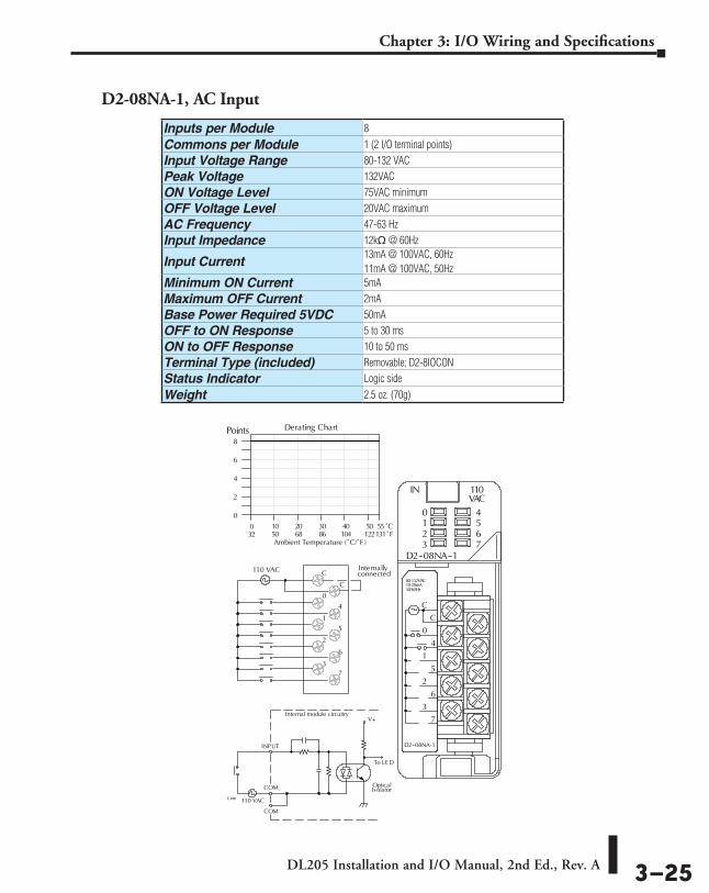
DL205 Installation and I/O Manual, 2nd Ed., Rev. A 3–25
Chapter 3: I/O Wiring and Specifications
D2-08NA-1, AC Input
Optical
COM
Isolator
INPUT
110 VAC
V+
To LE D
Internal module circuitry
COM
C
C
0
1
2
3
4
5
6
7
Internallyconnected110 VAC
0
2
4
6
8
0 10 20 30 40 50 55
Ambient Temperature (˚C/˚F )32 50 68 86 104 122131
C˚F˚
Points
C
C
0
4
1
5
2
6
3
7
80-132VAC10-20mA
D2--08NA-1
IN 110
D2--08NA--1
VAC0123
4567
50/60Hz
Line
Derating Chart
Inputs per Module 8
Commons per Module 1 (2 I/O terminal points)Input Voltage Range 80-132 VACPeak Voltage 132VACON Voltage Level 75VAC minimumOFF Voltage Level 20VAC maximumAC Frequency 47-63 HzInput Impedance 12kq @ 60Hz
Input Current13mA @ 100VAC, 60Hz 11mA @ 100VAC, 50Hz
Minimum ON Current 5mAMaximum OFF Current 2mABase Power Required 5VDC 50mAOFF to ON Response 5 to 30 msON to OFF Response 10 to 50 msTerminal Type (included) Removable; D2-8IOCONStatus Indicator Logic side
Weight 2.5 oz. (70g)

DL205 Installation and I/O Manual, 2nd Ed., Rev. A 3–26
Chapter 3: I/O Wiring and Specifications
D2-08NA-2, AC Input
Inputs per Module 8
Commons per Module 1 (2 I/O terminal points)Input Voltage Range 170-265 VACPeak Voltage 265VACON Voltage Level 150VAC minimumOFF Voltage Level 40VAC maximum AC Frequency 47-63 HzInput Impedance 18kq @ 60Hz
Input Current
9mA @ 220VAC, 50Hz11mA @ 265VAC, 50Hz 10mA @ 220VAC, 60Hz 12mA @ 265VAC, 60Hz
Minimum ON Current 10mAMaximum OFF Current 2mABase Power Required 5VDC 100mA
OFF to ON Response 5 to 30msON to OFF Response 10 to 50msTerminal Type (included) Removable; D2-8IOCON
Status Indicator Logic side
Weight 2.5 oz. (70g)
Operating Temperature 32ºF to 131ºF (0º to 55ºC)
Storage Temperature -4ºF to 158ºF (-20ºC to 70ºC)Humidity 35% to 95% (non-condensing)Atmosphere No corrosive gases permittedVibration MIL STD 810C 514.2Shock MIL STD 810C 516.2Insulation Withstand Voltage 1500VAC 1 minute (COM-GND)
10M Q @ 500VDC
Noise ImmunityNEMA 1500V 1 minuteSANKI 1000V 1 minute
RFI 150MHz, 430MHz
Optical
COM
Isolator
INPUT
220VAC
V+
To LE D
Internal module circuitry
COM
C
C
0
1
2
3
4
5
6
7
Internallyconnected
220VAC
0
2
4
6
8
0 10 20 30 40 50 55
Ambient Temperature (˚C/˚F )32 50 68 86 104 122131
C˚F˚
Points Derating Chart

DL205 Installation and I/O Manual, 2nd Ed., Rev. A 3–27
Chapter 3: I/O Wiring and Specifications
A
B
0 10 20 30 40 50 55
Ambient Temperature (˚C/˚F )32 50 68 86 104 122131
C˚F˚
OpticalIsolator
INPUT
110 VAC
V+
To LE D
Internal module circuitry
COM
0
1
2
3
5
6
7
NC
0
1
2
3
CB
4
5
6
7
CA
4
0
4
8
12
16Points
110 VAC
110 VAC
80--132VAC10--20mA
D2--16NA
IN 110
D2--16NA
VAC0123
4567
CA
4
5
6
7
CB
4
5
63
2
1
0
NC
3
2
1
0
7
50/60Hz
Derating Chart
IN SIM
F2--08SIM
0123
4567
ON>0
1
2
3
4
5
6
7
D2-16NA, AC Input F2-08SIM, Input Simulator
Inputs per Module 16
Commons per Module 2 (isolated)Input Voltage Range 80-132 VACPeak Voltage 132VACON Voltage Level 70VAC minimumOFF Voltage Level 20VAC maximumAC Frequency 47-63 HzInput Impedance 12kq @ 60Hz
Input Current11mA @ 100VAC, 50Hz13mA @ 100VAC, 60Hz15mA @ 132VAC, 60Hz
Minimum ON Current 5mAMaximum OFF Current 2mABase Power Required 5VDC 100mA
OFF to ON Response 5 to 30 msON to OFF Response 10 to 50 msTerminal Type (included) Removable; D2-16IOCON
Status Indicator Logic side
Weight 2.4 oz. (68g)
Inputs per Module 8Base Power Required 5VDC 50mA
Terminal Type NoneStatus Indicator Switch side
Weight 2.65 oz. (75g)
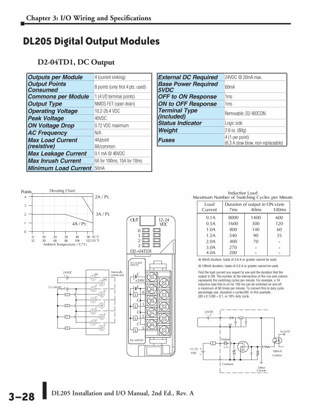
DL205 Installation and I/O Manual, 2nd Ed., Rev. A 3–28
Chapter 3: I/O Wiring and Specifications
DL205 Digital Output Modules
D2-04TD1, DC Output
Outputs per Module 4 (current sinking)Output Points Consumed 8 points (only first 4 pts. used)
Commons per Module 1 (4 I/O terminal points)Output Type NMOS FET (open drain)Operating Voltage 10.2-26.4 VDCPeak Voltage 40VDCON Voltage Drop 0.72 VDC maximumAC Frequency N/AMax Load Current (resistive)
4A/point8A/common
Max Leakage Current 0.1 mA @ 40VDCMax Inrush Current 6A for 100ms, 15A for 10ms
Minimum Load Current 50mA
External DC Required 24VDC @ 20mA max.Base Power Required 5VDC 60mA
OFF to ON Response 1msON to OFF Response 1msTerminal Type (included) Removable; D2-8IOCON
Status Indicator Logic sideWeight 2.8 oz. (80g)
Fuses 4 (1 per point)(6.3 A slow blow, non-replaceable)
0
1
2
3
4
0 10 20 30 40 50 55
Ambient Temperature (˚C/˚F )32 50 68 86 104 122131
C˚F˚
Points2A / Pt.
3A / Pt.
4A / Pt.
0V
24V
C
C
C
C
0
1
2
3
24VDC Internallyconnected
L
L
L
L
+
12--24VDC +
C
+24V
0
C1
C2
C3
10.2--26.4VDC50mA--4A
D2--04TD1
OUT 12--24
D2--04TD1
VDC0123
L
L
L
L
C
Common
L
12--24 +
--
+--24VDC
VDC
To LE D
Optical
Isolator
0V
Output
OtherCircuits
Reg
Inductive Load
0.1A 1400 6000.5A 300 1201.0A 140 601.5A 90 352.0A 70 --
Load
80001600
100ms
800540
3.0A400270 -- --
40ms7msCurrentDuration of output in ON state
4.0A 200 -- --
Maximum Number of Switching Cycles per Minute
6.3A
Derating Chart
At 40mS duration, loads of 3.0 A or greater cannot be used.
At 100mS duration, loads of 2.0 A or greater cannot be used.
Find the load current you expect to use and the duration that the output is ON. The number at the intersection of the row and column represents the switching cycles per minute. For example, a 1A inductive load that is on for 100 ms can be switched on and off a maximum of 60 times per minute. To convert this to duty cycle percentage use: (duration x cycles)/60. In this example, (60 x 0.1)/60 = 0.1, or 10% duty cycle.

DL205 Installation and I/O Manual, 2nd Ed., Rev. A 3–29
Chapter 3: I/O Wiring and Specifications
D2–08TD1, DC Output D2–08TD2, DC Output
OpticalIsolator
L
COM
COM
OUTPUT
12--24VDC
+
5A
Internal module circuitry
C
C
0
1
2
3
4
5
6
7
12--24VDC Internallyconnected
L
L
L
L
L
L
L
L
0
2
4
6
8
0 10 20 30 40 50 55
Ambient Temperature (˚C/˚F )32 50 68 86 104 122131
C˚F˚
Points
+
C
C
0
4
1
5
2
6
3
7
10.2--26.4VDC0.2mA-0.3A
D2--08TD1
OUT 12--24
D2--08TD1
VDC0123
4567
L
L
Derating Chart
Outputs per Module 8 (current sinking)
Commons per Module 1 (2 I/O terminal points)Output Type NPN open collectorOperating Voltage 10.2-26.4 VDCPeak Voltage 40VDCON Voltage Drop 1.5 VDC maximumAC Frequency N/AMinimum Load Current 0.5 mAMax Load Current 0.3 A/point; 2.4 A/commonMax Leakage Current 0.1 mA @ 40VDCMax Inrush Current 1A for 10msBase Power Required 5VDC 100mA
OFF to ON Response 1 msON to OFF Response 1 msTerminal Type (included) Removable; D2-8IOCONStatus Indicator Logic sideWeight 2.3 oz. (65g)
Fuses1 per common5A fast blow, non-replaceable
Outputs per Module 8 (current sourcing)
Commons per Module 1Output Type PNP open collectorOperating Voltage 12 to 24 VDCOutput Voltage 10.8 to 26.4 VDCPeak Voltage 40VDCON Voltage Drop 1.5 VDCAC Frequency N/AMinimum Load Current N/A
Max Load Current 0.3 A per point; 2.4 A per common
Max Leakage Current 1.0 mA @ 40VDCMax Inrush Current 1A for 10msBase Power Required 5VDC 100mA
OFF to ON Response 1msON to OFF Response 1msTerminal Type (included) Removable; D2-8IOCON
Status Indicator Logic sideWeight 2.1 oz. (60g)
Fuses1 per common5A fast blow, non-replaceable

DL205 Installation and I/O Manual, 2nd Ed., Rev. A 3–30
Chapter 3: I/O Wiring and Specifications
D2–16TD1–2, DC Output D2–16TD2–2, DC Output
OpticalIsolator
COM
OUTPUT
12--24+
Internal module circuitry
L
+V
+
24VDC
0 10 20 30 40 50 55
Ambient Temperature (˚C/˚F )32 50 68 86 104 122131
C˚F˚
0
4
8
12
16Points
0
1
2
3
5
6
7+V
0
1
2
3
C
4
5
6
7
C
4L
L
L
L
L
L
L
L
L
L
L
L
L
L
L
L
COM
Internallyconnected
12--24VDC
24VDC
A
B
10.2--26.4VDC 0.1A
OUT 12--24
D2--16TD1--2
VDC0123
4567
C
4
5
6
7
C
4
5
63
2
1
0
+V
3
2
1
0
7
CLASS2
A
B
+
+
VDC
*Can also be used with 5VDC supply
Derating Chart
Outputs per Module 16 (current sinking)
Commons per Module 1 (2 I/O terminal points)Output Type NPN open collectorExternal DC required 24VDC ±4V @ 80mA maxOperating Voltage 10.2-26.4 VDCPeak Voltage 30VDCON Voltage Drop 0.5 VDC maximumAC Frequency N/AMinimum Load Current 0.2 mA
Max Load Current0.1A/point1.6 A/common
Max Leakage Current 0.1 mA @ 30VDCMax Inrush Current 150mA for 10msBase Power Required 5VDC 200mA
OFF to ON Response 0.5 msON to OFF Response 0.5 msTerminal Type (included) Removable; D2-16IOCON
Status Indicator Logic sideWeight 2.3 oz. (65g)Fuses None
Outputs per Module 16 (current sourcing)
Commons per Module 2Output Type NPN open collectorOperating Voltage 10.2-26.4 VDCPeak Voltage 30 VDCON Voltage Drop 1.0 VDC maximumAC Frequency N/AMinimum Load Current 0.2 mA
Max Load Current0.1A/point1.6A/module
Max Leakage Current 0.1 mA @ 30 VDCMax Inrush Current 150 mA for 10 msBase Power Required 5VDC 200 mA
OFF to ON Response 0.5 msON to OFF Response 0.5 msTerminal Type (included) Removable; D2-16IOCON
Status Indicator Logic sideWeight 2.8 oz. (80g)
Fuses None
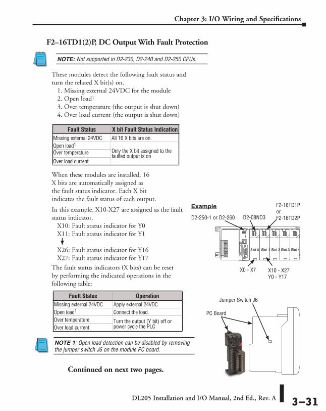
DL205 Installation and I/O Manual, 2nd Ed., Rev. A 3–31
Chapter 3: I/O Wiring and Specifications
F2–16TD1(2)P, DC Output With Fault Protection
When these modules are installed, 16 X bits are automatically assigned as the fault status indicator. Each X bit indicates the fault status of each output.
Fault Status X bit Fault Status IndicationMissing external 24VDC All 16 X bits are on.Open load1
Only the X bit assigned to the faulted output is on
Over temperature
Over load current
Fault Status OperationMissing external 24VDC Apply external 24VDCOpen load1 Connect the load.Over temperature Turn the output (Y bit) off or
power cycle the PLCOver load current
The fault status indicators (X bits) can be reset by performing the indicated operations in the following table:
NOTE 1: Open load detection can be disabled by removing the jumper switch J6 on the module PC board.
ExampleIn this example, X10-X27 are assigned as the fault status indicator. X10: Fault status indicator for Y0 X11: Fault status indicator for Y1 X26: Fault status indicator for Y16 X27: Fault status indicator for Y17
These modules detect the following fault status and turn the related X bit(s) on. 1. Missing external 24VDC for the module 2. Open load1 3. Over temperature (the output is shut down) 4. Over load current (the output is shut down)
NOTE: Not supported in D2-230, D2-240 and D2-250 CPUs.
Slot 0 Slot 1 Slot 2 Slot 3 Slot 4
D2-08ND3
F2-16TD1P or F2-16TD2P
X0 - X7 X10 - X27 Y0 - Y17
D2-250-1 or D2-260
Continued on next two pages.
PC Board
Jumper Switch J6

DL205 Installation and I/O Manual, 2nd Ed., Rev. A 3–32
Chapter 3: I/O Wiring and Specifications
Derating Chart
24VDC
Ambient Temperature (°C/°F)
0
4
8
12
16Points
0
1
2
3
5
6
724V
0
1
2
3
0V
4
5
6
7
4L
L
L
L
L
L
L
L
L
L
L
L
L
L
L
L
Internallyconnected
12–24VDC
A
B
10.2-26.4VDC 0.25ACLASS2
OUT 12-24
F2–16TD1P
VDC0123
4567
0V
4
5
6
7
0V
4
5
63
2
1
0
24V
3
2
1
0
7
A
B
+
+
When the A/B switch is in the A position,the LEDs display the output status of themodule’s first 8 output points. Positon Bdisplays the output status of the mod-ule’s second group of 8 output points.
0 10 20 30 40 50 55°C131°F32 50 68 86 104 122
0V
OpticalIsolator
0V
OUTPUT
12–24+
Internal module circuitry
L
24V
+24VDC
VDC0V
F2–16TD1P, DC Output With Fault Protection
NOTE 1: Not supported in D2-230, D2-240 and D2-250 CPUs. NOTE 2: Supporting Firmware: D2-250-1 must be V4.80 or later D2-260 must be V2.60 or later NOTE 3: This module does not currently support Think & Do 8.0. It does not support Think & Do Live! or Studio.
Inputs per module 16 (status indication)Outputs per module 16 (current sinking)Commons per module 1 (2 I/O terminal points)Output type NMOS FET (open drain)Operating voltage 10.2 -26.4 VDC, externalPeak voltage 40VDCAC frequency N/AON voltage drop 0.7 V (output current 0.5 A)Overcurrent trip 0.6 A min., 1.2 A max.
Maximum load current 0.25 A continuous, 0.5 A peak
Maximum OFF current Jumper J6 installed: 200eA; J6 removed: 30eA
Base power required 5V 70mAOFF to ON response 0.5 msON to OFF response 0.5 msTerminal type Removable (D2-16IOCON)Status indicators Logic SideWeight 2.0 oz. (25g)Fuses NoneExternal DC required 24VDC ±10% @ 50mA
External DC overvoltage shutdown
27V, outputs are restored when voltage is within limits

DL205 Installation and I/O Manual, 2nd Ed., Rev. A 3–33
Chapter 3: I/O Wiring and Specifications
Derating Chart
24VDC
Ambient T emperature ( ° C/ ° F)
0
4
8
12
16 Points
0
1
2
3
5
6
7 24V
0
1
2
3
0V
4
5
6
7
4 L
L
L
L
L
L
L
L
L
L
L
L
L
L
L
L
A
B
10.2-26.4 VDC 0.25A CLASS2
OUT 12-24
F2–16TD2P
VDC 0 1 2 3
4 5 6 7
0V
4
5
6
7 0V
4
5
6 3
2
1
0
24V
3
2
1
0
7
A
B
+
When the A/B switch is in the A position, the LEDs display the output status of themodule’ s first 8 output points. Positon B displays the output status of the mod- ule’ s second group of 8 output points.
0 10 20 30 40 50 55°C 131°F 32 50 68 86 104 122
0V12–24VDC+
24V
0V
L
+–24VDC
0V
OUTPUT
Reg
12–24VDC+
Optical Isolator
F2–16TD2P, DC Output with Fault Protection
Inputs per module 16 (status indication)Outputs per module 16 (current sourcing)Commons per module 1Output type NMOS FET (open source)Operating voltage 10.2 -26.4 VDC, externalPeak voltage 40 VDCAC frequency N/AON voltage drop 0.7 V (output current 0.5 A)Overcurrent trip 0.6 A min., 1.2 A max.
Maximum load current 0.25 A continuous, 0.5 A peak
Maximum OFF current Jumper J6 installed: 200eA; J6 removed: 30eA
Base power required 5V 70mAOFF to ON response 0.5 msON to OFF response 0.5 msTerminal type Removable (D2-16IOCON)Status indicators Logic SideWeight 2.0 oz. (25g)Fuses NoneExternal DC required
24 VDC R/S10% @ 50 mA
External DC overvoltage shutdown
27 V, outputs are restored when voltage is within limits
NOTE 1: Not supported in D2-230, D2-240 and D2-250 CPUs. NOTE 2: Supporting Firmware: D2-250-1 must be V4.80 or later D2-260 must be V2.60 or later NOTE 3: This module does not currently support Think & Do 8.0. It does not support Think & Do Live! or Studio.
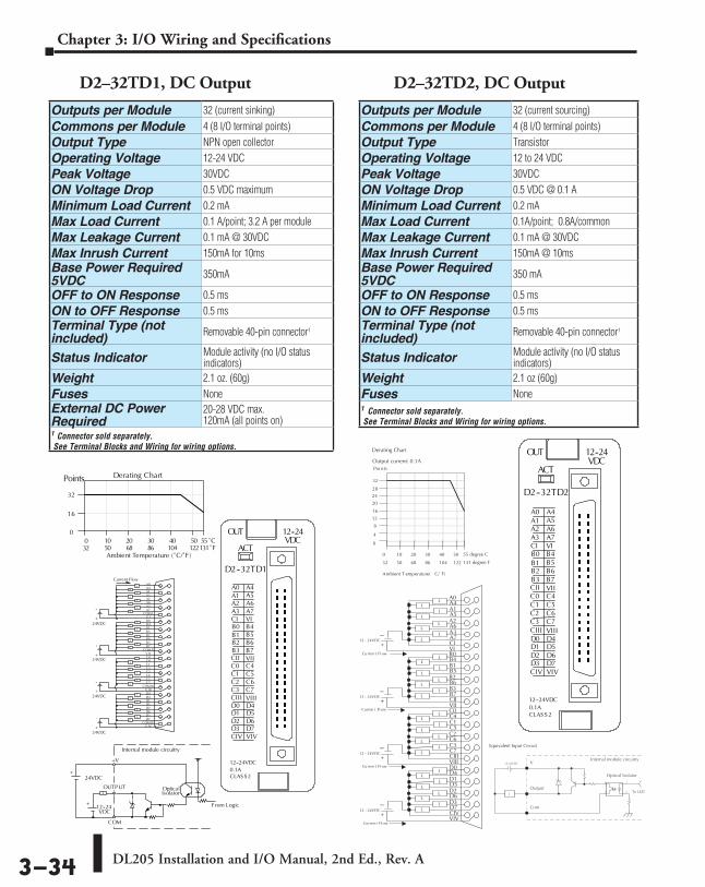
DL205 Installation and I/O Manual, 2nd Ed., Rev. A 3–34
Chapter 3: I/O Wiring and Specifications
D2–32TD1, DC Output D2–32TD2, DC Output
Outputs per Module 32 (current sinking)
Commons per Module 4 (8 I/O terminal points)Output Type NPN open collectorOperating Voltage 12-24 VDCPeak Voltage 30VDCON Voltage Drop 0.5 VDC maximumMinimum Load Current 0.2 mAMax Load Current 0.1 A/point; 3.2 A per moduleMax Leakage Current 0.1 mA @ 30VDCMax Inrush Current 150mA for 10msBase Power Required 5VDC 350mA
OFF to ON Response 0.5 msON to OFF Response 0.5 msTerminal Type (not included) Removable 40-pin connector1
Status Indicator Module activity (no I/O status indicators)
Weight 2.1 oz. (60g)Fuses NoneExternal DC Power Required
20-28 VDC max. 120mA (all points on)
1 Connector sold separately. See Terminal Blocks and Wiring for wiring options.
Outputs per Module 32 (current sourcing)
Commons per Module 4 (8 I/O terminal points)Output Type TransistorOperating Voltage 12 to 24 VDCPeak Voltage 30VDCON Voltage Drop 0.5 VDC @ 0.1 AMinimum Load Current 0.2 mAMax Load Current 0.1A/point; 0.8A/commonMax Leakage Current 0.1 mA @ 30VDCMax Inrush Current 150mA @ 10msBase Power Required 5VDC 350 mA
OFF to ON Response 0.5 msON to OFF Response 0.5 msTerminal Type (not included) Removable 40-pin connector1
Status Indicator Module activity (no I/O status indicators)
Weight 2.1 oz (60g)Fuses None 1 Connector sold separately. See Terminal Blocks and Wiring for wiring options.

DL205 Installation and I/O Manual, 2nd Ed., Rev. A 3–35
Chapter 3: I/O Wiring and Specifications
F2–08TA, AC Output D2–08TA, AC Output
Outputs per Module 8
Commons per Module 2 (Isolated)Output Type SSR (Triac with zero crossover)Operating Voltage 24-140 VACPeak Voltage 140VACON Voltage Drop 1.6 V(rms) @ 1.5 AAC Frequency 47 to 63 HzMinimum Load Current 50mA
Max Load Current1.5 A / pt @ 30ºC 1.0 A / pt @ 60ºC 4.0 A / common; 8.0 A / module @ 60ºC
Max Leakage Current 0.7 mA (rms)Peak One Cycle Surge Current 15A
Base Power Required 5VDC 250mA
OFF to ON Response 0.5 ms - 1/2 cycleON to OFF Response 0.5 ms - 1/2 cycleTerminal Type (included) Removable; D2-8IOCON
Status Indicator Logic sideWeight 3.5 oz.
Fuses None
Outputs per Module 8
Commons per Module 1 (2 I/O terminal points)Output Type SSR (Triac)Operating Voltage 15-264 VACPeak Voltage 264VAC
ON Voltage Drop< 1.5 VAC (>0.1A)< 3.0 VAC (<0.1A)
AC Frequency 47 to 63 HzMinimum Load Current 10mAMax Load Current 0.5 A/point; 4A/common
Max Leakage Current4mA (264VAC, 60Hz)1.2 mA (100VAC, 60Hz)0.9 mA (100VAC, 50Hz)
Max Inrush Current 10A for 10msBase Power Required 5VDC 250mA
OFF to ON Response 1ms ON to OFF Response 1ms + 1/2 cycleTerminal Type (included) Removable; D2-8IOCON
Status Indicator Logic sideWeight 2.8 oz. (80g)
Fuses 1 per common, 6.3 A slow blow, non-replaceable
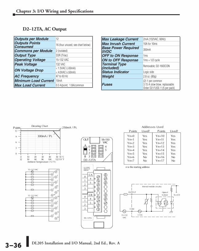
DL205 Installation and I/O Manual, 2nd Ed., Rev. A 3–36
Chapter 3: I/O Wiring and Specifications
D2–12TA, AC Output
Addresses Used
YesYesYesYesYes
Points
Yn+0Yn+1Yn+2Yn+3Yn+4Yn+5 Yes
Used?
NoYn+6Yn+7 No
n is the starting address
YesYesYesYesYes
Points
Yn+10Yn+11Yn+12Yn+13Yn+14Yn+15 Yes
Used?
NoYn+16Yn+17 No
Optical
COM
IsolatorOUTPUT
To LE D
Internal module circuitry
3.15A15--132
L
0
3
6
9
12Points
VAC
250mA / Pt.
300mA / Pt.
0
1
2
3
5
NC
NC
NC
0
1
2
3
CB
4
5
NC
NC
CA
4L
L
L
L
L
L
L
L
L
L
15--132 VAC
15--132 VAC
0 10 20 30 40 50 55
Ambient Temperature (˚C/˚F )32 50 68 86 104 122131
C˚F˚
A
B
15--132VAC10mA--0.3A
D2--12TA
OUT 18--110
D2--12TA
VAC0123
45
CA
4
5
CB
4
5
3
2
1
0
3
2
1
0
50/60 Hz
L
L
Derating Chart
Outputs per Module 12Outputs Points Consumed 16 (four unused, see chart below)
Commons per Module 2 (isolated)Output Type SSR (Triac)Operating Voltage 15-132 VACPeak Voltage 132 VAC
ON Voltage Drop< 1.5VAC (>50mA)< 4.0VAC (<50mA)
AC Frequency 47 to 63 HzMinimum Load Current 10mA
Max Load Current 0.3 A/point; 1.8A/common
Max Leakage Current 2mA (132VAC, 60Hz)
Max Inrush Current 10A for 10msBase Power Required 5VDC 350mA
OFF to ON Response 1msON to OFF Response 1ms + 1/2 cycleTerminal Type (included) Removable; D2-16IOCON
Status Indicator Logic sideWeight 2.8 oz. (80g)
Fuses(2) 1 per common3.15 A slow blow, replaceableOrder D2-FUSE-1 (5 per pack)

DL205 Installation and I/O Manual, 2nd Ed., Rev. A 3–37
Chapter 3: I/O Wiring and Specifications
NC
NC
C0
C1
C2
C3
0
1
2
3
L
L
L
L
5--30 VDCNC
NCC0
0
C1
1
C2
2
C3
3
5-240VAC4A50/60Hz
D2--04TRS
OUT RELAY
D2--04TRS
0123
L
5--30VDC10mA--4A
L
L
L
5--240 VAC
0
1
2
3
4
0 10 20 30 40 50 55
Ambient Temperature (˚C/˚F )32 50 68 86 104 122 131
C˚F˚
Points2A /Pt.
3A /Pt.
4A /Pt.
COM
OUTPUT
To LE D
Internal module circuitry
6.3A5--240 VAC
L
5--30 VDC
Derating Chart
D2–04TRS, Relay Output
Outputs per Module 4Outputs Points Consumed 8 (only 1st 4pts. are used)
Commons per Module 4 (isolated)Output Type Relay, form A (SPST)Operating Voltage 5-30 VDC / 5-240 VACPeak Voltage 30VDC, 264VACON Voltage Drop 0.72 VDC maximumAC Frequency 47 to 63 HzMinimum Load Current 10mAMax Load Current (resistive) 4A/point; 8A/module (resistive)
Max Leakage Current 0.1 mA @ 264VAC
Max Inrush Current 5A for < 10msBase Power Required 5VDC 250mA
OFF to ON Response 10msON to OFF Response 10msTerminal Type (included) Removable; D2-8IOCONStatus Indicator Logic sideWeight 2.8 oz. (80g)
Fuses1 per point6.3 A slow blow, replaceableOrder D2-FUSE-3 (5 per pack)
Typical Relay Life (Operations)Voltage & Load CurrentType of Load 1A 2A 3A 4A24 VDC Resistive 500k 200k 100k 50k24 VDC Solenoid 100k 40k –– –110 VAC Resistive 500k 250k 150k 100k110 VAC Solenoid 200k 100k 50k –220 VAC Resistive 350k 150k 100k 50k220 VAC Solenoid 100k 50k –– ––At 24 VDC, solenoid (inductive) loads over 2A cannot be used.
At 100 VAC, solenoid (inductive) loads over 3A cannot be used.
At 220 VAC, solenoid (inductive) loads over 2A cannot be used.

DL205 Installation and I/O Manual, 2nd Ed., Rev. A 3–38
Chapter 3: I/O Wiring and Specifications
D2–08TR, Relay Output
0
2
4
6
8
Points
0.5A / Pt.
COM
OUTPUT
To LE D
Internal module circuitry
6.3A5--240 VAC
L
5--30 VDC
1A / Pt.
C
C
0
1
2
3
4
5
6
7
Internallyconnected
L
L
L
L
L
L
L
L
5--240 VAC5--30 VDC 0 10 20 30 40 50 55
Ambient Temperature (°C/°F )32 50 68 86 104 122131
C°F°C
C
0
4
1
5
2
6
3
7
5-240VAC1A50/60Hz
D2--08TR
OUT RELAY
D2--08TR
0123
4567
L
L
5--30VDC5mA--1A
Derating Chart
Outputs per Module 8 Outputs Points Consumed 8
Commons per Module 1 (2 I/O terminals)Output Type Relay, form A (SPST)Operating Voltage 5-30 VDC; 5-240 VACPeak Voltage 30VDC, 264VACON Voltage Drop N/A AC Frequency 47 to 60 HzMinimum Load Current 5mA @ 5VDCMax Load Current (resistive) 1A/point; 4A/common
Max Leakage Current 0.1 mA @ 265VAC
Max Inrush Current Output: 3A for 10msCommon: 10A for 10ms
Base Power Required 5VDC 250mA
OFF to ON Response 12msON to OFF Response 10msTerminal Type (included) Removable; D2-8IOCONStatus Indicator Logic sideWeight 3.9 oz. (110g)
Fuses One 6.3 A slow blow, replaceableOrder D2-FUSE-3 (5 per pack)
Typical Relay Life (Operations)Voltage/Load Current Closures 24 VDC Resistive 1A 500k 24 VDC Solenoid 1A 100k110 VDC Resistive 1A 500k110 VDC Solenoid 1A 200k220 VAC Resistive 1A 350k220 VAC Solenoid 1A 100k

DL205 Installation and I/O Manual, 2nd Ed., Rev. A 3–39
Chapter 3: I/O Wiring and Specifications
OUT RELAY
F2--08TR
0123
45
12--250VAC10A50/60Hz12--28VDC10ma--10A
67
L
Common
NO
Typical Circuit
12--250VAC12--28VDC
Internal Circuitry
0
2
4
6
8
0 10 20 30 40 50 55
Ambient Temperature (°C/°F )32 50 68 86 104 122 131
C°F°
10 A/pt.
NumberPoints On
(100% dutycycle)
NO 4
NO 5
C4-7
NO 2
NO 3
NO 1
C0-3
NO 0
NO 6
NO 7
Derating Chart
L
L
L
L
L
L
L
L
3 A/pt.
2.5 A/pt.
5A/pt.
F2–08TR, Relay Output
Outputs per Module 8 Outputs Points Consumed 8
Commons per Module 2 (isolated), 4-pts. per commonOutput Type 8, Form A (SPST normally open)
Operating Voltage7A @ 12-28 VDC, 12-250 VAC;0.5 A @ 120VDC
Peak Voltage 150VDC, 265 VACON Voltage Drop N/A AC Frequency 47 to 63HzMinimum Load Current 10mA @ 12VDCMax Load Current (resistive)
10A/point 3 (subject to derating)Max of 10A/common
Max Leakage Current N/AMax Inrush Current 12A Base Power Required 5VDC 670mA
OFF to ON Response 15ms (typical)ON to OFF Response 5ms (typical)Terminal Type (included) Removable; D2-8IOCONStatus Indicator Logic sideWeight 5.5 oz. (156g)
Fuses None
Typical Relay Life1 (Operations) at Room Temperature
Voltage &Type of Load 2 Load Current 50mA 5A 7A
24 VDC Resistive 10M 600k 300k 24 VDC Solenoid - 150k 75k110 VDC Resistive – 600k 300k110 VDC Solenoid – 500k 200k220 VAC Resistive – 300k 150k220 VAC Solenoid – 250k 100k1) Contact life may be extended beyond those values shown with the use of arc suppression techniques described in the DL205 User Manual. Since these modules have no leakage current, they do not have built-in snubber. For example, if you place a diode across a 24 VDC inductive load, you can significantly increase the life of the relay.
2) At 120 VDC 0.5A resistive load, contact life cycle is 200k cycles.
3) Normally closed contacts have 1/2 the current handling capability of the normally open contacts.
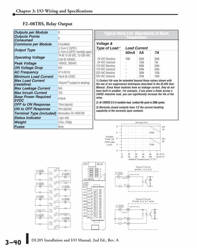
DL205 Installation and I/O Manual, 2nd Ed., Rev. A 3–40
Chapter 3: I/O Wiring and Specifications
F2–08TRS, Relay Output
12--250VAC7A50/60Hz
OUT RELAY
F2--08TRS
0123
45
NO 0
C0
NC 0
C3
NO 3
C5
NO 5
NC 7
C7NO 6
C6
NC 6
NO 4
C4
NO 2
C2
NO 1
C1
NO7
12--28VDC10ma--7A
67
L
Common
NO
Typical Circuit
L
Common
NO
NCL
12--250VAC12--28VDC
12--250VAC12--28VDC
Internal Circuitry
Internal Circuitry
Typical Circuit(Points 0, 6, & 7 only)
(points 1,2,3,4,5)
0
2
4
6
8
5A/pt.
0 10 20 30 40 50 55
Ambient Temperature (°C/°F )32 50 68 86 104 122131
C°F°
4A/pt.
7A/pt.
6A/pt.
NumberPoints On
(100% dutycycle)
C6
C7
NC 6
NC 7
NO 4
NO 5
C4
C5
NO 2
NO 3
C2
C3
NO 1
NC 0
C1
C0
NO 0
NO 6
NO 7
L
12--28VDC12--250VAC
L
12--28VDC12--250VAC
L
12--28VDC12--250VAC
L
12--28VDC12--250VAC
L
12--28VDC12--250VAC
Lnormally closed
L
12--28VDC12--250VAC
Lnormally closed
L
12--28VDC12--250VAC
L
12--28VDC12--250VAC
L
normally closed
Derating Chart
Outputs per Module 8Outputs Points Consumed 8
Commons per Module 8 (isolated)
Output Type 3, Form C (SPDT)5, Form A (SPST normally open)
Operating Voltage7A @ 12-28 VDC, 12-250 VAC0.5A @ 120VDC
Peak Voltage 150VDC, 265VACON Voltage Drop N/AAC Frequency 47 to 63 HzMinimum Load Current 10mA @ 12VDCMax Load Current (resistive) 7A/point 3 (subject to derating)
Max Leakage Current N/AMax Inrush Current 12ABase Power Required 5VDC 670mA
OFF to ON Response 15ms (typical)ON to OFF Response 5ms (typical)Terminal Type (included) Removable; D2-16IOCONStatus Indicator Logic sideWeight 5.5oz. (156g)
Fuses None
Typical Relay Life1 (Operations) at Room Temperature
Voltage &Type of Load 2 Load Current 50mA 5A 7A
24 VDC Resistive 10M 600k 300k 24 VDC Solenoid - 150k 75k110 VDC Resistive – 600k 300k110 VDC Solenoid – 500k 200k220 VAC Resistive – 300k 150k220 VAC Solenoid – 250k 100k1) Contact life may be extended beyond those values shown with the use of arc suppression techniques described in the DL205 User Manual. Since these modules have no leakage current, they do not have built-in snubber. For example, if you place a diode across a 24VDC inductive load, you can significantly increase the life of the relay.
2) At 120VDC 0.5 A resistive load, contact life cycle is 200k cycles.
3) Normally closed contacts have 1/2 the current handling capability of the normally open contacts.
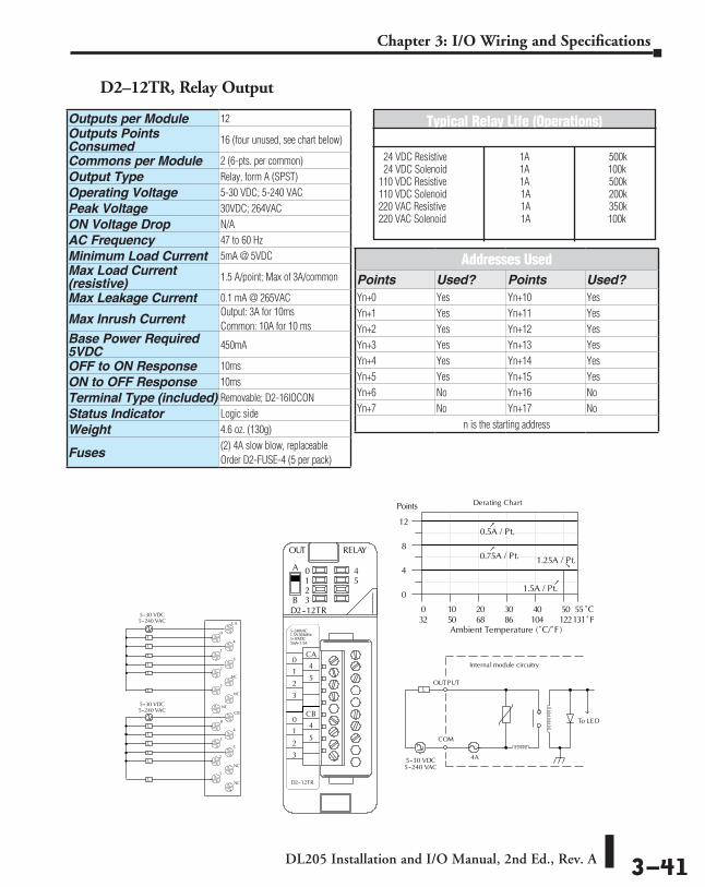
DL205 Installation and I/O Manual, 2nd Ed., Rev. A 3–41
Chapter 3: I/O Wiring and Specifications
D2–12TR, Relay Output
A
B
5--240VAC1.5A50/60Hz
D2--12TR
OUT RELAY
D2--12TR
0123
45
CA
4
5
CB
4
5
3
2
1
0
3
2
1
0
5--30VDC
0
4
8
12
Points
COM
OUTPUT
To LE D
Internal module circuitry
4A
5--240 VAC
L
5--30 VDC
0.5A / Pt.
0 10 20 30 40 50 55
Ambient Temperature (˚C/˚F )32 50 68 86 104 122131
C˚F˚
1.5A / Pt.
0.75A / Pt.
5mA--1.5A
0
1
2
3
5
NC
NC
NC
0
1
2
3
CB
4
5
NC
NC
CA
4L
L
L
L
L
L
L
L
L
L
L
L
5--240 VAC5--30 VDC
5--240 VAC5--30 VDC
1.25A / Pt.
Derating Chart
Outputs per Module 12Outputs Points Consumed 16 (four unused, see chart below)
Commons per Module 2 (6-pts. per common)Output Type Relay, form A (SPST)Operating Voltage 5-30 VDC; 5-240 VACPeak Voltage 30VDC; 264VACON Voltage Drop N/AAC Frequency 47 to 60 HzMinimum Load Current 5mA @ 5VDCMax Load Current (resistive) 1.5 A/point; Max of 3A/common
Max Leakage Current 0.1 mA @ 265VAC
Max Inrush CurrentOutput: 3A for 10msCommon: 10A for 10 ms
Base Power Required 5VDC 450mA
OFF to ON Response 10msON to OFF Response 10msTerminal Type (included) Removable; D2-16IOCONStatus Indicator Logic sideWeight 4.6 oz. (130g)
Fuses(2) 4A slow blow, replaceableOrder D2-FUSE-4 (5 per pack)
Addresses UsedPoints Used? Points Used?Yn+0 Yes Yn+10 YesYn+1 Yes Yn+11 YesYn+2 Yes Yn+12 YesYn+3 Yes Yn+13 YesYn+4 Yes Yn+14 YesYn+5 Yes Yn+15 YesYn+6 No Yn+16 NoYn+7 No Yn+17 No
n is the starting address
Typical Relay Life (Operations)Voltage/Load Current Closures 24 VDC Resistive 1A 500k 24 VDC Solenoid 1A 100k110 VDC Resistive 1A 500k110 VDC Solenoid 1A 200k220 VAC Resistive 1A 350k220 VAC Solenoid 1A 100k

DL205 Installation and I/O Manual, 2nd Ed., Rev. A 3–42
Chapter 3: I/O Wiring and Specifications
D2–08CDR, 4 pt. DC Input / 4pt. Relay Output
CA
0
0
1
1
2
2
3
3
CB
D2--08CDR20--28VDC
8mA
L
IN/ 24VDC
D2--08CDR
RELAY0123
0123
OUTA B
0
1
2
3
4Points
Out-puts
1A / Pt.
Derating Chart
COM
OUTPUT
To LE D
Internal module circuitry
6.3A
5--240 VAC
L
5--30 VDC
CA
O
0
1
2
3
1
2
3
CB
L
5--240 VAC5--30 VDC
0 10 20 30 40 50 55
Ambient Temperature (°C/°F )32 50 68 86 104 122131
C°F°
L
L
L
5--240VAC1A50/60Hz5--30VDC5mA--1A
Inputs5mA /
Pt.
OpticalCOM Isolator
INPUT
24VDC
V+
To LE D
Internal module circuitry
+
L
L
L
24VDC
+ --Sink
Source
Sink
Source
General SpecificationsBase Power Required 5VDC 200mA
Terminal Type (included) Removable; D2-8IOCON
Status Indicator Logic sideWeight 3.5 oz. (100g)Input SpecificationsInputs per Module 4 (sink/source)Input Points Consumed 8 (only first 4-pts. are used)Commons per Module 1Input Voltage Range 20-28 VDCPeak Voltage 30VDCON Voltage Level 19VDC minimumOFF Voltage Level 7VDC maximumAC Frequency N/AInput Impedance 4.7 kq
Input Current 5mA @ 24VDCMaximum Current 8mA @ 30VDCMinimum ON Current 4.5 mAMaximum OFF Current 1.5 mAOFF to ON Response 1 to 10 msON to OFF Response 1 to 10 ms
Fuses (input circuits) None
Output SpecificationsOutputs per Module 4Outputs Points Consumed 8 (only first 4-pts. are used)
Commons per Module 1Output Type Relay, form A (SPST)Operating Voltage 5-30 VDC; 5-240 VACPeak Voltage 30VDC; 264VACON Voltage Drop N/AAC Frequency 47 to 63 HzMinimum Load Current 5mA @ 5VDCMax Load Current (resistive) 1A/point ; 4A/module
Max Leakage Current 0.1 mA @ 264VAC
Max Inrush Current 3A for < 100ms 10A for < 10ms (common)
OFF to ON Response 12msON to OFF Response 10ms
Fuses (output circuits) 1 (6.3A slow blow, replaceable); Order D2-FUSE-3 (5 per pack)
Typical Relay Life (Operations)Voltage/Load Current Closures24 VDC Resistive 1A 500k24 VDC Solenoid 1A 100k110 VDC Resistive 1A 500k110 VDC Solenoid 1A 200k220 VAC Resistive 1A 350k220 VAC Solenoid 1A 100k

DL205 Installation and I/O Manual, 2nd Ed., Rev. A 3–43
Chapter 3: I/O Wiring and Specifications
NOTES:

DL205 Installation and I/O Manual, 2nd Ed., Rev. A 3–44
Chapter 3: I/O Wiring and Specifications
DL205 Analog Input Modules
F2-04AD-1 4-Channel 4-20mA Analog Input Module
This module can be powered by either a 12VDC or 24VDC power supply, and is a direct replacement for F2-04AD-1L modules.
Number of Channels 4, single ended (1 common)
Input Ranges 4 to 20 mA current
Resolution 12-bit (1 in 4096)
Active Low-pass Filtering-3 dB at 120 Hz,2 poles(-12 dB per octave)
Input Impedance 250q ±0.1%, 1/2W current input
Absolute Maximum Ratings -40mA to +40mA, current input
Converter Type Successive approximation
Conversion Time (PLC Update Rate)
1 channel per scan maximum (D230 CPU);4 channels per scan maximum (D2-240, D2-250(-1), D2-260, and D2-262 CPUs)
Linearity Error (End to End) ±1 count (0.025% of full scale) maximum
Input Stability ±1 count
Full Scale Calibration Error (offset error not included) ±12 counts max., @ 20 mA current input
Offset Calibration Error ±7 counts max.,@ 4mA current input
Step Response 4.9 ms to 95% of F.S. change
Maximum Inaccuracy ±.5% @ 77ºF (25ºC)±.65% 32º to 140ºF (0º to 60ºC)
Accuracy vs.Temperature ±50 ppm/ºC maximum full scale (including max. offset change)
Recommended Fuse 0.032 A, Series 217 fast-acting, current inputs
Digital Input Points Required 16 (X) input points (12 binary data bits, 2 channel ID bits, 2 diagnostic bits)
Base Power Required 5 VDC 100mA
External Power Supply 5mA maximum, +10 to +30 VDC
Operating Temperature 32º to 140ºF (0º to 60ºC)
Storage Temperature -4º to 158°F (-20º to 70ºC)
Relative Humidity 5 to 95% (non-condensing)
Environmental Air No corrosive gases permitted
Shock & Vibration MIL STD 810C 514.2
Noise Immunity NEMA ICS3-304
Terminal Type (included) Removable; D2-8IOCON
One count in the specification table is equal to one least significant bit of the analog data value (1 in 4096).
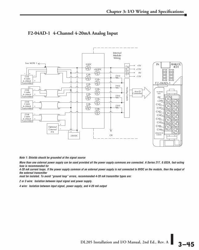
DL205 Installation and I/O Manual, 2nd Ed., Rev. A 3–45
Chapter 3: I/O Wiring and Specifications
F2-04AD-1 4-Channel 4-20mA Analog Input
Note 1: Shields should be grounded at the signal source
More than one external power supply can be used provided all the power supply commons are connected. A Series 217, 0.032A, fast-acting fuse is recommended for 4-20 mA current loops. If the power supply common of an external power supply is not connected to 0VDC on the module, then the output of the external transmitter must be isolated. To avoid “ground loop” errors, recommended 4-20 mA transmitter types are:
2 or 3 wire: Isolation between input signal and power supply.
4 wire: Isolation between input signal, power supply, and 4-20 mA output
CH14--wire
4--20mATransmitter
Optional
OV
A to DConverter
InternalModuleWiring
Analog
Sw
itch
+
--E xternalP/S
250
See NOTE 1
250
250
250
CH23--wire
4--20mATransmitter
CH32-wire
4--20mATransmitter
CH42-wire
4--20mATransmitter
+
--
+
--
+
--
+
---- +
+
0VDC
+24VDC
CH1--
CH2--
CH3--
CH4--
CH4+
CH3+
CH2+
CH1+
+ --
24VDC
+24VCH1--CH1+
CH2--CH2+
CH3--CH3+
CH4--CH4+
IN ANALOG
F2--04AD--1
4CH
0V
DC
toD
CC
onverter
+5V
+15V
0V
--15V
10-30VDC5mA
ANALOG IN4-20mA

DL205 Installation and I/O Manual, 2nd Ed., Rev. A 3–46
Chapter 3: I/O Wiring and Specifications
One count in the specification table is equal to one least significant bit of the analog data value (1 in 4096).
Number of Channels 8, single ended (1 common)
Input Ranges 4 to 20 mA current
Resolution 12-bit (1 in 4096)
Low-pass Filtering -3dB at 200Hz, (-6dB per octave)
Input Impedance 250q ±0.1%, 1/2W current input
Absolute Maximum Ratings -45mA to +45mA
Converter Type Successive approximation
Conversion Time (PLC Update Rate)
(D2-230 CPU) 1 channel per scan maximum(D2-240, D2-250(-1), D2-260, and D2-262 CPUs) 8 channels per scan maximum
Linearity Error (End to End) ±1 count (0.025% of full scale) maximum
Input Stability ±1 count
Full Scale Calibration Error (offset error not included) ±5 counts max., @ 20mA current input
Offset Calibration Error ±2 counts max., @ 4mA current input
Step Response 1 ms to 95% of F.S. change
Maximum Inaccuracy ±.1% @ 77ºF (25ºC)±.25% 32º to 140ºF (0º to 60ºC)
Accuracy vs.Temperature ±50 ppm/ºC maximum full scale (including max. offset change of two counts)
Recommended Fuse 0.032 A, Series 217 fast-acting, current inputs
Digital Input Points Required16 (X) input points(12 binary data bits, 3 channel ID bits, 1 broken transmitter bit)
Base Power Required 5VDC 100mA
External Power Supply 5mA maximum, +10 to +30 VDC
Operating Temperature 32º to 140ºF (0º to 60ºC)
Storage Temperature -4º to 158ºF (-20º to 70ºC)
Relative Humidity 5 to 95% (non-condensing)
Environmental Air No corrosive gases permitted
Shock & Vibration MIL STD 810C 514.2
Noise Immunity NEMA ICS3-304
Terminal Type (included) Removable; D2-8IOCON
F2-08AD-1 8-Channel 4-20mA Analog Input Module

DL205 Installation and I/O Manual, 2nd Ed., Rev. A 3–47
Chapter 3: I/O Wiring and Specifications
CH14--wire
4--20mATransmitter
Optional
OV
A to DConverter
InternalModuleWiring
Analog
Sw
itch
+
--E xternalP/S
250
See NOTE 1
250
250
250
CH43--wire
4--20mATransmitter
CH62-wire
4--20mATransmitter
CH82-wire
4--20mATransmitter
+
--
+
--
+
--
+
---- +
+
0VDC
+24VDC
CH1+
CH3+
CH5+
CH7+
CH8+
CH6+
CH4+
CH2+
+--
24VDC
+24VCH1+CH2+
CH3+CH4+
CH5+CH6+
CH7+CH8+
0V
DC
toD
CC
onverter
+5V
+15V
0V
--15V
ANALOG8CH
IN
F2-08AD-1
10-30VDC5mA
ANALOG IN4-20mA
Note 1: Shields should be grounded at the signal source.
More than one external power supply can be used provided all the power supply commons are connected. A Series 217, 0.032A, fast-acting fuse is recommended for 4-20 mA current loops. If the power supply common of an external power supply is not connected to 0 VDC on the module, then the output of the external transmitter must be isolated. To avoid “ground loop” errors, recommended 4-20 mA transmitter types are:
2 or 3 wire: Isolation between input signal and power supply. 4 wire: Isolation between input signal, power supply, and 4-20 mA output
F2-08AD-1 8-Channel 4-20mA Analog Input
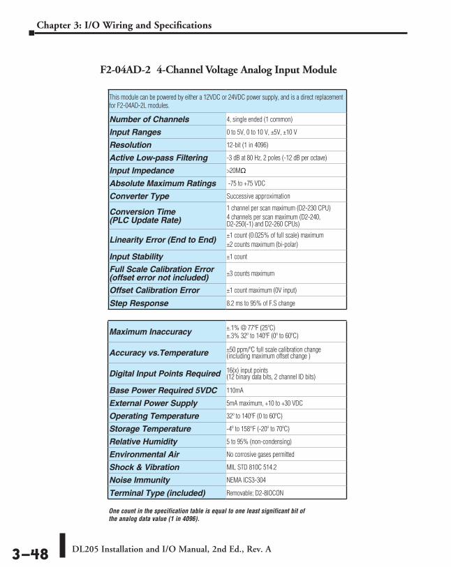
DL205 Installation and I/O Manual, 2nd Ed., Rev. A 3–48
Chapter 3: I/O Wiring and Specifications
This module can be powered by either a 12VDC or 24VDC power supply, and is a direct replacement for F2-04AD-2L modules.
Number of Channels 4, single ended (1 common)
Input Ranges 0 to 5V, 0 to 10 V, ±5V, ±10 V
Resolution 12-bit (1 in 4096)
Active Low-pass Filtering -3 dB at 80 Hz, 2 poles (-12 dB per octave)
Input Impedance >20Mq
Absolute Maximum Ratings -75 to +75 VDC
Converter Type Successive approximation
Conversion Time (PLC Update Rate)
1 channel per scan maximum (D2-230 CPU)4 channels per scan maximum (D2-240, D2-250(-1) and D2-260 CPUs)
Linearity Error (End to End)±1 count (0.025% of full scale) maximum±2 counts maximum (bi-polar)
Input Stability ±1 count
Full Scale Calibration Error (offset error not included) ±3 counts maximum
Offset Calibration Error ±1 count maximum (0V input)
Step Response 8.2 ms to 95% of F.S change
Maximum Inaccuracy ±.1% @ 77ºF (25ºC)±.3% 32º to 140ºF (0º to 60ºC)
Accuracy vs.Temperature ±50 ppm/ºC full scale calibration change (including maximum offset change )
Digital Input Points Required 16(x) input points (12 binary data bits, 2 channel ID bits)
Base Power Required 5VDC 110mA
External Power Supply 5mA maximum, +10 to +30 VDC
Operating Temperature 32º to 140ºF (0 to 60ºC)
Storage Temperature -4º to 158°F (-20º to 70ºC)
Relative Humidity 5 to 95% (non-condensing)
Environmental Air No corrosive gases permitted
Shock & Vibration MIL STD 810C 514.2
Noise Immunity NEMA ICS3-304
Terminal Type (included) Removable; D2-8IOCON
F2-04AD-2 4-Channel Voltage Analog Input Module
One count in the specification table is equal to one least significant bit of the analog data value (1 in 4096).

DL205 Installation and I/O Manual, 2nd Ed., Rev. A 3–49
Chapter 3: I/O Wiring and Specifications
CH1Voltage
Transmitter
OV
A to DConverter
InternalModuleWiring
Analog
Sw
itchS ee NOTE 1
+
--
+
---- +
+
0VDC
+24VDC
CH1--
CH2--
CH3--
CH4--
CH4+
CH3+
CH2+
CH1+
Typical User Wiring + --
18--26.4VDC
+24V
CH1--
CH1+
CH2--
CH2+
CH3--
CH3+
CH4--
CH4+
IN ANALOG
F2--04AD--2
4CH
0V
CH1
CH2
CH3
CH4
24V
0V
+
--+
+
--+
CH2Voltage
Transmitter
CH3Voltage
Transmitter
CH4Voltage
Transmitter
DC
toD
CC
onverter+5V
+15V
0V
--15V
10-30VDC5mA
ANALOG IN0-5,0-10VDC+/-5,+/-10VDC
Note 1: Shields should be grounded at the signal source.
F2-04AD-2 4-Channel Voltage Analog Input

DL205 Installation and I/O Manual, 2nd Ed., Rev. A 3–50
Chapter 3: I/O Wiring and Specifications
F2-08AD-2 8-Channel Voltage Analog Input Module
One count in the specification table is equal to one least significant bit of the analog data value (1 in 4096). Includes circuitry to automatically detect broken or open transmitters.
Number of Channels 8, single ended (1 common)
Input Ranges 0 to 5V, 0 to 10 V, ±5V, ±10 VDC
Resolution 12 bit (1 in 4095) uni-polar13 bit (-4095 to 4095) bi-polar
Active Low-pass Filtering-3dB at 200 Hz, (-6dB per octave)
Input Impedance >20Mq
Absolute Maximum Ratings -75 to +75 VDC
Converter Type Successive approximation
Conversion Time (PLC Update Rate)
1 channel per scan maximum (D2-230 CPU)8 channels per scan maximum (D2-240, D2-250(-1) and D2-260 CPUs)
Linearity Error (End to End) ±1 count (0.025% of full scale) maximum
Input Stability ±1 count
Full Scale Calibration Error (offset error not included) ±3 counts maximum
Offset Calibration Error ±1 count maximum (0V input)
Step Response 1ms to 95% of F.S. change
Maximum Inaccuracy ±.1% @ 77ºF (25ºC)±.3% 32º to 140ºF (0º to 60ºC)
Accuracy vs.Temperature ±50 ppm/ºC maximum full scale(including max. offset change of 2 counts)
Digital Input Points Required16 (X) input points, (12 binary data bits, 3 channel ID bits, 1 sign bit, 1 diagnostic bit)
Base Power Required 5VDC 100mA
External Power Supply 5mA maximum, +10 to +30 VDC
Operating Temperature 32º to 140ºF (0º to 60ºC)
Storage Temperature -4º to 158ºF (-20º to 70ºC)
Relative Humidity 5 to 95% (non-condensing)
Environmental Air No corrosive gases permitted
Shock & Vibration MIL STD 810C 514.2
Noise Immunity NEMA ICS3-304
Terminal Type (included) Removable; D2-8IOCON

DL205 Installation and I/O Manual, 2nd Ed., Rev. A 3–51
Chapter 3: I/O Wiring and Specifications
F2-08AD-2 8-Channel Voltage Analog Input
+24V
CH1+
CH2+
CH3+
CH4+
CH5+
CH6+
CH7+
CH8+
IN ANALOG
F2--08AD--2
0V
10-30VDC5mA
ANALOG IN0-5,0-10VDC+/-5,+/-10VDC
AD
C
VoltageTransmitter
VoltageTransmitter
VoltageTransmitter
VoltageTransmitter
CH1
CH3
+
CH5
+
CH7
+
0 VDC
24VDC
+ -
CH2
CH4
+
CH6
+
CH8
+
CH1
CH2
CH3
CH4
24VDC
Analog M
ultiplexer
+
+
0V
3-wire
2-wire
4-wire
3-wire
+
-
++
+
+
++
-
-
-
-
Note 1: Shields should be grounded at the signal source. Note 2: Connect all external power supply commons. Note 3: Connect unused channels (CH5+, CH6+, CH7+, CH8+ in this example) to 0VDC.

DL205 Installation and I/O Manual, 2nd Ed., Rev. A 3–52
Chapter 3: I/O Wiring and Specifications
DL205 RTD and Thermocouple Modules
F2-04RTD 4-Channel RTD Input Module
Number of Channels 4
Input Ranges
Type Pt100: -200.0/850.0ºC, -328/1562ºFType Pt1000: -200.0/595.0ºC, -328/1103ºFType jPt100: -38.0/450.0ºC, -36/842ºFType CU-10/25ž: -200.0/260.0ºC, -328/500ºF
Resolution 16 bit (1 in 65535)
Display Resolution ±0.1ºC, ±0.1ºF (±3276.7)
RTD Excitation Current 200µA
Input Type Differential
Notch Filter>100 db notches at 50/60 Hz -3db=13.1Hz
Maximum Setting Time 100ms (full-scale step input)
Common Mode Range 0-5 VDC
Absolute Maximum Ratings Fault protected inputs to ±50 VDC
Sampling Rate 160 ms per channel
Converter Type Charge Balancing
Linearity Error ±.05ºC maximum, ±.01ºC typical
Maximum Inaccuracy ±1ºC
PLC Update Rate 4 channel/scan max., 240/250(-1)/D2-260CPUs1 channel per scan max., 230 CPU
Digital Input Points Required 32 input points (16 binary data bits,2 channel ID bits, 4 fault bits)
Base Power Required 5VDC 90mA
Operating Temperature 32° to 140°F (0° to 60°C)
Storage Temperature -4º to 158ºF (-20º to 70ºC)
Temperature Drift None (self-calibrating)
Relative Humidity 5 to 95% (non-condensing)
Environmental Air No corrosive gases permitted
Shock & Vibration MIL STD 810C 514.2
Noise Immunity NEMA ICS3-304
Terminal Type (included) Removable; D2-8IOCON

DL205 Installation and I/O Manual, 2nd Ed., Rev. A 3–53
Chapter 3: I/O Wiring and Specifications
F2-04RTD 4-Channel RTD Input
A/D+-
Ch1
Ch2
Ch3 --
Ch4 --
Ch1+
Ch2 +
Ch3 +
Ch4 +
CC
200 ACurrentS ource
200 ACurrentS ource
Ref.Adj.
xNote 2
Note 1
CH1+
CH2--
CH2+
COM
COM
CH3--
CH3+
CH4--
CH4+
F2-04RTD
INTEMP
F2--04RTD
CH1--
RTD
RTDINPUT
-
-
0V
Analog M
ultiplexer
Notes:1. The three wires connecting the RTD to the module must be the same type and length. Do not use the shield or drain wire for the third connection.
2. If an RTD sensor has four wires, the plus sense wire should be left unconnected as shown.
3. This module is not compatible with the ZIPLink wiring systems.
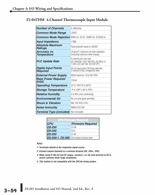
DL205 Installation and I/O Manual, 2nd Ed., Rev. A 3–54
Chapter 3: I/O Wiring and Specifications
F2-04THM 4-Channel Thermocouple Input Module
Notes:
1: Terminate shields at the respective signal source.
2: Connect unused channels to a common terminal (0V, CH4+, CH4).
3: When using 0-156 mV and 5V ranges, connect (-) or (0) volts terminal to 0V to ensure common mode range acceptance.
4. This module is not compatible with the ZIPLink wiring system.
Number of Channels 4, differential
Common Mode Range ±5VDC
Common Mode Rejection 90dB min. @ DC, 150dB min. @ 50/60 Hz.
Input Impedance 1 Mq
Absolute Maximum Ratings Fault-protected inputs to ±50VDC
Accuracy vs. Temperature
±5 ppm/ºC maximum full scale calibration (including maximum offset change)
PLC Update Rate4 channels per scan max.D2-240/250(-1)/D2-260 CPU, H2-EBC(-F); 1 chan. per scan max. D2-230 CPU
Digital Input Points Required
32 (X) input points (16 binary data bits, 2 channel ID bits, 4 diagnostic bits)
External Power Supply 60mA maximum, 18 to 26.4 VDC
Base Power Required 5VDC 110mA
Operating Temperature 32º to 140ºF (0º to 60ºC)
Storage Temperature -4º to 158ºF (-20º to 70ºC)
Relative Humidity 5 to 95% (non-condensing)
Environmental Air No corrosive gases permitted
Shock & Vibration MIL STD 810C 514.2
Noise Immunity NEMA ICS3-304
Terminal Type (included) Non-removable
CPU Firmware RequiredCPU Firmware RequiredD2-230 V1.06D2-240 V2.5D2-250 V1.06
D2-250-1, D2-260 All firmware versions work

DL205 Installation and I/O Manual, 2nd Ed., Rev. A 3–55
Chapter 3: I/O Wiring and Specifications
F2-04THM 4-Channel Thermocouple Input
VoltageTransmitter
Analog
Mux
AD
C
CH3+
CH4+
CH3
CH4
0V
Module S upply
24VDC +24VDC
CH1+
CH2+
CH1
CH2
IN TEMP
F2--04THM
VOLT
CH1CH2+CH2CH3+CH3CH4+CH4+24V
0V
CH1+Analog
Mux
AD
C
VoltageTransmitter
VoltageTransmitter
0V
TransmitterS upply
+--
24VDC
+24VDC
Module S upply
CH1+
CH2+
CH3+
CH4+
CH1
CH2
CH3
CH4
0V0V
Input Ranges
Type J -190 to 760ºC -310 to 1400ºFType E -210 to 1000ºC -346 to 1832ºFType K -150 to 1372ºC -238 to 2502ºFType R 65 to 1768ºC 149 to 3214ºFType S 65 to 1768ºC 149 to 3214ºFType T -230 to 400ºC -382 to 752ºFType B 529 to 1820ºC 984 to 3308ºFType N -70 to 1300ºC -94 to 2372ºFType C 65 to 2320ºC 149 to 4208ºF
Display Resolution ±0.1ºC or ±0.1ºF
Cold Junction Compensation Automatic
Conversion Time 100ms per channel
Warm-Up Time 30 minutes typically ± 1ºC repeatability
Linearity Error (End to End) ±.05ºC maximum, ±.01ºC typical
Maximum Inaccuracy ±3ºC (excluding thermocouple error)
Voltage Input Specifications
Voltage Ranges 0-5V, ±5V, 0-156.25 mV, ±156.25 mVDC
Resolution 16 bit (1 in 65535)
Full Scale Calibration Error (Offset Error Included) ±13 counts typical ±33 maximum
Offset Calibration Error ±1 count maximum, @ 0V input
Linearity Error (End to End) ±1 count maximum
Maximum Inaccuracy ±.02% @ 25ºC (77ºF)
Voltage input wiring diagram
See Notes 1 and 2 See Notes 2 and 3
Thermocouple input wiring diagram

DL205 Installation and I/O Manual, 2nd Ed., Rev. A 3–56
Chapter 3: I/O Wiring and Specifications
One count in the specification table is equal to one least significant bit of the analog data value (1 in 4096).
This module requires a 24VDC user power supply for operation. See the F2-02DA-1L on the next page if you want to use a 12VDC supply. All other specifications are the same.
Number of Channels 2
Output Ranges 4 to 20 mA
Resolution 12 bit (1 in 4096)
Output Type Single ended, one common
Digital Output Points Required 16 (Y) output points(12 binary data bits, 2 channel ID bits)
Maximum Loop Supply 30VDC
Peak Output Voltage 40VDC (clamped by transient voltage suppressor)
Load Impedance 0q minimum
Maximum Load/Power Supply 620q/18 V, 910q/24 V, 1200q/ 30V
PLC Update Rate1 channel per scan maximum D2-230 CPU2 channels per scan maximum (D2-240, D2-250(-1) and D2-260 CPUs)
Linearity Error (end to end) ±1 count (±0.025% of full scale) maximum
Conversion Settling Time 100µs maximum (full scale change)
Full Scale Calibration Error (offset error included) ± 5 counts max., 20mA @77ºF (25ºC)
Offset Calibration Error ± 3 counts max., 4mA @ 77ºF (25Cº)
Accuracy vs. Temperature ±50 ppm/ºC full scale calibration change (including maximum offset change of 2 counts)
Maximum Inaccuracy 0.1% @ 77ºF (25ºC)0.3% @ 32º to 140ºF (0º to 60ºC)
Base Power Required 5VDC 40mA
External Power Supply 18 to 30 VDC, 60mA. (add 20 mA for each current loop used)
Operating Temperature 32º to 140ºF (0º to 60ºC)
Storage Temperature -4 to 158ºF(-20 to 70ºC)
Relative Humidity 5% to 95% (non-condensing)
Environmental Air No corrosive gases permitted
Shock & Vibration MIL STD 810C 514.2
Noise Immunity NEMA ICS3-304
Terminal Type (included) Removable; D2-8IOCON
F2-02DA-1 2-Channel 4-20mA Analog Output Module
DL205 Analog Output Modules

DL205 Installation and I/O Manual, 2nd Ed., Rev. A 3–57
Chapter 3: I/O Wiring and Specifications
OV
+ --
24 VDC
See
0VDC
+24VDC
N/C
N/C
N/C
N/C
NOTE 1
60mA
+24VCH1--CH1+
CH2--CH2+NCNC
NCNC
18--30VDC60mA
F2--02DA--1
OUT ANALOG
F2--02DA--1
2CH
ANALOGOUT4--20mA
0V
CH1--
CH2--
CH1+
CH2+Current sinkingCh 1
Current sinkingCh 2
DC
toD
CC
onverter+5V
+15V
0V
--15V
D to AConverter
D to AConverter
Ch 1 load250Ω typical
Ch 2 load250Ω typical
InternalModuleWiring
Transient protectedprecision digital to analogconverter output circuits
Typical user wiring
NOTE 1: Shields should be connected to the 0V of the module or the OV of the R/S. NOTE 2: Unused current outputs should remain open (no connections) for minimum power consumption.
F2-02DA-1 2-Channel 4-20mA Analog Output

DL205 Installation and I/O Manual, 2nd Ed., Rev. A 3–58
Chapter 3: I/O Wiring and Specifications
F2-02DA-1L 2-Channel 4-20mA Analog Output Module
One count in the specification table is equal to one least significant bit of the analog data value (1 in 4096).
This module requires a 12 VDC user power supply for operation. See the F2-02DA-1 on the previous page if you want to use a 24 VDC supply. All other specifications are the same.
Number of Channels 2
Output Ranges 4 to 20 mA
Resolution 12 bit (1 in 4096)
Output Type Single ended, 1 common
Digital Output Points Required 16(Y) output points(12 binary data bits, 2 channel ID bits)
Maximum Loop Supply 30VDC
Peak Output Voltage 40VDC (clamped by transient voltage suppressor)
Load Impedance 0q minimum
Maximum Load/Power Supply 620q/18V, 910q/24V, 1200q/30V
PLC Update Rate1 channel per scan maximum (D2-230 CPU)2 channels per scan maximum (D2-240, D2-250(-1) and D2-260 CPUs)
Linearity Error (end to end) ±1 count (0.025% of full scale) maximum
Conversion Settling Time 100 µs maximum (full scale change)
Full Scale Calibration Error (offset error included) ±5 counts max., 20 mA @ 77ºF (25ºC)
Offset Calibration Error ±3 counts max., 4mA @ 77ºF (25ºC)
Accuracy vs. Temperature ±50 ppm/ºC full scale calibration change (including maximum offset change of 2 counts)
Maximum Inaccuracy +0.1% @ 77ºF (25ºC)±0.3% @ 32 to 140°F (0 to 60°C)
Base Power Required 5VDC 40mA
External Power Supply 10 to 15 VDC, 70 mA (add 20 mA for each current loop used)
Operating Temperature 32º to 140ºF (0º to 60ºC)
Storage Temperature -4º to 158ºF (-20º to 70ºC)
Relative Humidity 5 to 95% (non-condensing)
Environmental Air No corrosive gases permitted
Shock & Vibration MIL STD 810C 514.2
Noise Immunity NEMA ICS3-304
Terminal Type (included) Removable; D2-8IOCON

DL205 Installation and I/O Manual, 2nd Ed., Rev. A 3–59
Chapter 3: I/O Wiring and Specifications
F2-02DA-1L 2-Channel 4-20mA Analog Output
OV
+ --
12 VDC
See
0VDC
+12VDC
N/C
N/C
N/C
N/C
NOTE 1
70mA + 20mAfor each loop
+ V
CH1--
CH1+
CH2--
CH2+
NC
NC
NC
NC
10--15 VDC70mA
F2--02DA--1L
OUT ANALOG
F2--02DA--1L
2CH
ANALOGOUT4--20mA
0V
CH1--
CH2--
CH1+
CH2+
Current s inkingCh 1
Current s inkingCh 2
DC
toD
CC
onverter
+5V
+15V
0V
--15V
D to AConverter
D to AConverter
12
Ch 1 load250Ω typical
Ch 2 load250Ω typical
InternalModuleWiring
Transient protectedprecision digital to analogconverter output circuits
Typical User Wiring
Maximum user load is dependent upon loop power supply.
Loop power supply Load range (ohm)15 VDC 0 to 45012 VDC 0 to 30010 VDC 0 to 200
NOTE 1: Shields should be connected to the 0V of the module or the OV of the P/S.
NOTE 2: Unused current outputs should remain open (no connections) for minimum power consumption.

DL205 Installation and I/O Manual, 2nd Ed., Rev. A 3–60
Chapter 3: I/O Wiring and Specifications
F2-02DAS-1 2-Channel Isolated 4-20mA Analog Output Module
Number of Channels 2, isolated
Output Ranges 4 to 20 mA
Resolution 16 bit (1 in 65536)
Output Type Current sourcing
Digital Output Points Required32 (Y) output points(16 binary data bits, 2 channel ID bits, 1 output enable bit)
Isolation Voltage ±750 V continuous, channel to channel, channel to logic
Base Power Required 5VDC 100mA
Loop Supply 18-32 VDC
External Power Supply 18-32 VDC @ 50 mA per channel
Output Loop Compliance Vin - 2.5V
Load Impedance 0-1375 q (@ 32 V)
Maximum Load/ Power Supply 375 q/12 V, 975 q/24 V, 1375 q/32 V
PLC Update Rate1 channel per scan maximum (D2-230 CPU)2 channels per scan maximum (D2-240, D2-250(-1) and D2-260 CPUs)
Conversion Settling Time 3ms to 0.1% of full scale
Linearity Error (end to end) ±10 count (±0.015% of full scale) maximum
Gain Calibration Error ±32 counts (±0.05%)
Offset Calibration Error ±13 counts (±0.02%)
Output Drift 50 ppm/ºC
Maximum Inaccuracy 0.07% @ 25ºC (77ºF)0.18% 0 to 60ºC (32º to 140ºF)
Operating Temperature 0º to 60ºC (32º to 140ºF)
Storage Temperature -20º to 70ºC (-4º to 158ºF)
Relative Humidity 5 to 95% (non-condensing)
Environmental air No corrosive gases permitted
Shock & Vibration MIL STD 810C 514.2
Noise Immunity NEMA ICS3-304
Terminal Type (included) Removable; D2-8IOCON
One count in the specification table is equal to one least significant bit of the analog data value (1 in 65536).
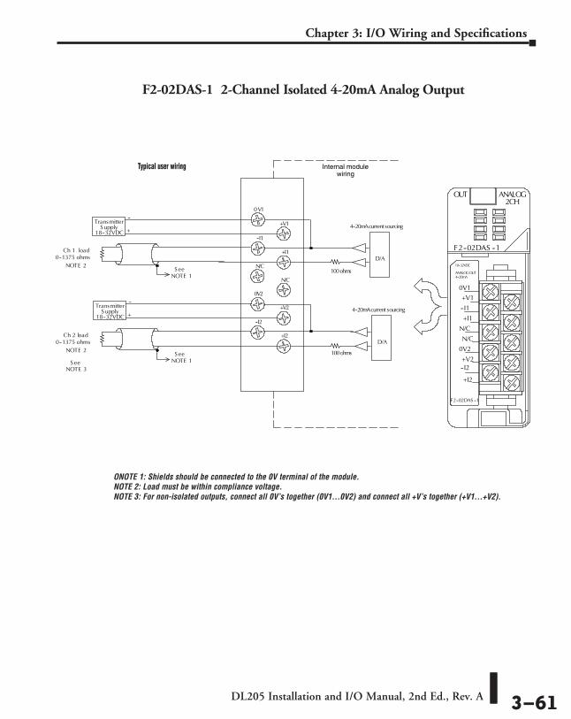
DL205 Installation and I/O Manual, 2nd Ed., Rev. A 3–61
Chapter 3: I/O Wiring and Specifications
F2-02DAS-1 2-Channel Isolated 4-20mA Analog Output
Internal modulewiring
+
--Transmitter
S ee
0V1
+V1
0V2
--I2
+I2
+V2
NOTE 1
+V1
--I1
+I1
N/C
N/C
0V2
+V2--I2
+I2
4--20mA
18--32VDC
F2--02DAS --1
OUT ANALOG
F2--02DAS --1
2CH
0V1
--I1
N/C
+I1
N/C
Ch 1 load0--1375 ohms
NOTE 2
S upply18--32VDC
S eeNOTE 1
Ch 2 load0--1375 ohms
NOTE 2
D/A
4--20mAcurrent sourcing
D/A
4--20mAcurrent sourcing
ANALOGOUT100ohms
100ohms
NOTE 3S ee
+
--Transmitter
S upply18--32VDC
Typical user wiring
ONOTE 1: Shields should be connected to the 0V terminal of the module. NOTE 2: Load must be within compliance voltage. NOTE 3: For non-isolated outputs, connect all 0V’s together (0V1…0V2) and connect all +V’s together (+V1…+V2).

DL205 Installation and I/O Manual, 2nd Ed., Rev. A 3–62
Chapter 3: I/O Wiring and Specifications
F2-08DA-1 8-Channel 4-20mA Analog Output Module
Linearity Error (end to end) ±2 count (±0.050% of full scale) maximum
Full Scale Calibration Error± 12 counts max. sinking @ any load ± 12 counts max. sourcing @ 125 q load ± 18 counts max. sourcing @ 250 q load ± 26 counts max. sourcing @ 400 q load
Offset Calibration Error± 9 counts max. sinking @ any load ± 9 counts max. sourcing @ 125 q load ± 11 counts max. sourcing @ 250 q load ± 13 counts max. sourcing @ 400 q load
Maximum Full Scale Inaccuracy @ 60ºC
0.5% sinking (any load) sinking & sourcing @ 125 q load 0.64% sourcing @ 250 q load 0.83% sourcing @ 400 q load
Maximum Full Scale Inaccuracy @ 25ºC (Incudes all errors and temp drift)
0.3% sinking (any load) sinking & sourcing @ 125 q load 0.44% sourcing @ 250 q load 0.63% sourcing @ 400 q load
Operating Temperature 32º to 140ºF (0º to 60ºC)
Storage Temperature -4 to 158ºF(-20 to 70ºC)
Relative Humidity 5% to 95% (non-condensing)
Environmental air No corrosive gases permitted
Shock & Vibration MIL STD 810C 514.2
Noise Immunity NEMA ICS3-304
Terminal Type (included) Removable; D2-16IOCON
Number of Channels 8, single-ended
Output Ranges 4 to 20 mA
Resolution 12 bit (1 in 4096)
Output Type Current sinking or current sourcing
Digital Output Points Required16 (Y) output points(12 binary data bits, 3 channel ID bits, 1 output enable bit)
Base Power Required 5VDC 30mA
Maximum Loop Voltage 30VDC
External Power Supply 18 to 30 VDC, 50 mA., class 2(add 20 mA for each current loop used)
Source Load 0-400 q @ 18-30 VDC
Sink Load 0-600 q/18V, 0-900 q/24 V, 0-1200 q/30 V
Total Load (sink + source) 600 q/18 V, 900 q/24 V, 1200 q/30 V
PLC Update Rate1 channel per scan maximum (D2-230 CPU)8 channels per scan maximum (D2-240, D2-250(-1) and D2-260 CPUs)
Conversion Settling Time 400µs maximum (full scale change)

DL205 Installation and I/O Manual, 2nd Ed., Rev. A 3–63
Chapter 3: I/O Wiring and Specifications
F2-08DA-1 8-Channel 4-20mA Analog Output
NOTE 1: Shields should be connected to the 0V of the module.
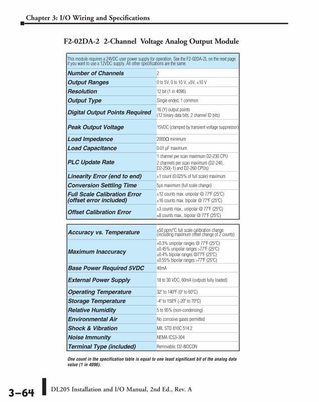
DL205 Installation and I/O Manual, 2nd Ed., Rev. A 3–64
Chapter 3: I/O Wiring and Specifications
This module requires a 24VDC user power supply for operation. See the F2-02DA-2L on the next page if you want to use a 12VDC supply. All other specifications are the same.
Number of Channels 2
Output Ranges 0 to 5V, 0 to 10 V, ±5V, ±10 V
Resolution 12 bit (1 in 4096)
Output Type Single ended, 1 common
Digital Output Points Required 16 (Y) output points(12 binary data bits, 2 channel ID bits)
Peak Output Voltage 15VDC (clamped by transient voltage suppressor)
Load Impedance 2000q minimum
Load Capacitance 0.01 µF maximum
PLC Update Rate1 channel per scan maximum D2-230 CPU2 channels per scan maximum (D2-240, D2-250(-1) and D2-260 CPUs)
Linearity Error (end to end) ±1 count (0.025% of full scale) maximum
Conversion Settling Time 5µs maximum (full scale change)
Full Scale Calibration Error (offset error included)
±12 counts max. unipolar @ 77ºF (25ºC)±16 counts max. bipolar @ 77ºF (25ºC)
Offset Calibration Error±3 counts max., unipolar @ 77ºF (25ºC) ±8 counts max., bipolar @ 77ºF (25ºC)
Accuracy vs. Temperature ±50 ppm/ºC full scale calibration change (including maximum offset change of 2 counts)
Maximum Inaccuracy+0.3% unipolar ranges @ 77ºF (25ºC)±0.45% unipolar ranges >77ºF (25ºC)±0.4% bipolar ranges @77ºF (25ºC)±0.55% bipolar ranges >77ºF (25ºC)
Base Power Required 5VDC 40mA
External Power Supply 18 to 30 VDC, 60mA (outputs fully loaded)
Operating Temperature 32º to 140ºF (0º to 60ºC)
Storage Temperature -4º to 158ºF (-20º to 70ºC)
Relative Humidity 5 to 95% (non-condensing)
Environmental Air No corrosive gases permitted
Shock & Vibration MIL STD 810C 514.2
Noise Immunity NEMA ICS3-304
Terminal Type (included) Removable; D2-8IOCON
F2-02DA-2 2-Channel Voltage Analog Output Module
One count in the specification table is equal to one least significant bit of the analog data value (1 in 4096).

DL205 Installation and I/O Manual, 2nd Ed., Rev. A 3–65
Chapter 3: I/O Wiring and Specifications
OV
InternalModuleWiring
+ --
24 VDC
Typical User Wiring
See
Ch 2 load2K
0VDC
+24VDC
N/C
N/C
N/C
N/C
NOTE 1
60mA
CH1--
CH2--
CH1+
CH2+
Voltage s ink/source
Trans ient protected precis iondigital to analog converter
output circuits
Ch 1
minimum
Ch 1 load2K
minimum
Voltage s ink/sourceCh 2
+24V
CH1--
CH1+
CH2--
CH2+
NC
NC
NC
NC
18--30VDC60mA
F2--02DA--2
OUT ANALOG
F2--02DA--2
2CH
ANALOGOUT0--5VDC
0V--5--+5VDC
0--10VDC--10--+10VDC
DC
toD
CC
onverter+5V
+15V
0V
--15V
D to AConverter
D to AConverter
Typical user wiring Internal module wiring
NOTE 1: Shields should be connected to the 0V of the module or the OV of the R/S.
NOTE 2: Unused voltage outputs should remain open (no connections) for minimum power consumption.
F2-02DA-2 2-Channel Voltage Analog Output

DL205 Installation and I/O Manual, 2nd Ed., Rev. A 3–66
Chapter 3: I/O Wiring and Specifications
This module requires a 12 VDC user power supply for operation. See the F2-02DA-2 on the previous page if you want to use a 24 VDC supply. All other specifications are the same.
Number of Channels 2
Output Ranges 0 to 5V, 0 to 10 V, ±5V, ±10 V
Resolution 12-bit (1 in 4096)
Output Type Single ended, 1 common
Digital Output Points Required 16 (Y) output points(12 binary data bits, 2 channel ID bits)
Peak Output Voltage 15VDC (clamped by transient voltage suppressor)
Load Impedance 2000 q minimum
Load Capacitance .01 µF maximum
PLC Update Rate1 channel per scan maximum (D2-230 CPU)2 channels per scan maximum (D2-240, D2-250(-1), D2-260, and D2-262 CPUs)
Linearity Error (end to end) ±1 count (0.025% of full scale) maximum
Conversion Settling Time 5µs maximum (full scale change)
Full Scale Calibration Error (offset error included)
±12 counts max. unipolar @ 77ºF (25ºC)±16 counts max. bipolar @ 77ºF (25ºC)
Offset Calibration Error±3 counts max., unipolar @ 77ºF (25ºC) ±8 counts max., bipolar @ 77ºF (25ºC)
Accuracy vs. Temperature ±50 ppm/ºC full scale calibration change (including maximum offset change of 2 counts)
Maximum Inaccuracy+0.3% unipolar ranges @ 77ºF (25ºC)±0.45% unipolar ranges >77ºF (25ºC)±0.4% bipolar ranges @77ºF (25ºC)±0.55% bipolar ranges >77ºF (25ºC)
Base Power Required 5VDC 40mA
External Power Supply 10 to 15 VDC, 70 mA (outputs fully loaded)
Operating Temperature 32º to 140ºF (0º to 60ºC)
Storage Temperature -4º to 158ºF (-20º to 70ºC)
Relative Humidity 5 to 95% (non-condensing)
Environmental Air No corrosive gases permitted
Shock & Vibration MIL STD 810C 514.2
Noise Immunity NEMA ICS3-304
Terminal Type (included) Removable; D2-8IOCON
F2-02DA-2L 2-Channel Voltage Analog Output Module
One count in the specification table is equal to one least significant bit of the analog data value (1 in 4096).
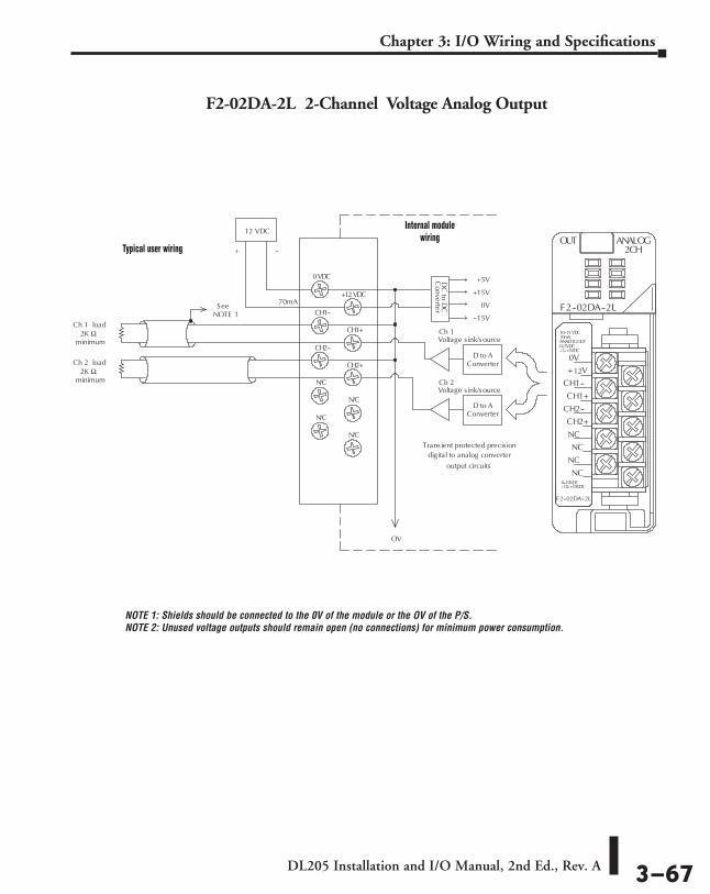
DL205 Installation and I/O Manual, 2nd Ed., Rev. A 3–67
Chapter 3: I/O Wiring and Specifications
NOTE 1: Shields should be connected to the 0V of the module or the OV of the P/S. NOTE 2: Unused voltage outputs should remain open (no connections) for minimum power consumption.
F2-02DA-2L 2-Channel Voltage Analog Output
OV
InternalModuleWiring
+ --
12 VDC
See
Ch 2 load2K
0VDC
+12VDC
N/C
N/C
N/C
N/C
NOTE 1
70mA
CH1--
CH2--
CH1+
CH2+
Voltage s ink/source
Trans ient protected precis iondigital to analog converter
output circuits
Ch 1
minimum
Ch 1 load2K
minimum
Voltage s ink/sourceCh 2
+ V
CH1--
CH1+
CH2--
CH2+
NC
NC
NC
NC
10--15 VDC70mA
F2--02DA--2L
OUT ANALOG
F2--02DA--2L
2CH
ANALOGOUT0--5VDC
0V--5--+5VDC
0--10VDC--10--+10VDC
DC
toD
CC
onverter+5V
+15V
0V
--15V
D to AConverter
D to AConverter
12
Typical user wiring
Internal module wiring

DL205 Installation and I/O Manual, 2nd Ed., Rev. A 3–68
Chapter 3: I/O Wiring and Specifications
F2-02DAS-2 2-Channel 0-5 V, 0-10 V Isolated Analog Output Module
Number of Channels 2, isolated
Output Ranges 0-5 V, 0-10 V
Resolution 16 bit (1 in 65536)
Output Type Sourced through external loop supply
Digital Output Points Required 32 (Y) output points (16 binary data bits, 2 channel ID bits)
Isolation Voltage ±750V continuous, channel to channel, channel to logic
Base Power Required 5VDC 60mA
External Power Supply 21.6-26.4 VDC @ 60 mA per channel
Load Impedance 2kq min
PLC Update Rate1 channel per scan maximum (D2-230 CPU)2 channels per scan maximum (D2-240, D2-250(-1), D2-260, and D2-262 CPUs)
Conversion Settling Time 3ms to 0.1% of full scale
Linearity Error (end to end) ±10 count (±0.015% of full scale) maximum
Gain Calibration Error ±32 counts (±0.05%)
Offset Calibration Error ±13 counts (±0.02%)
Output Drift 50 ppm/ºC
Maximum Inaccuracy 0.07% @ 25ºC (77ºF)0.18% 0 to 60ºC (32º to 140ºF)
Operating Temperature 0º to 60ºC (32º to 140ºF)
Storage Temperature -20º to 70ºC (-4º to 158ºF)
Relative Humidity 5 to 95% (non-condensing)
Environmental air No corrosive gases permitted
Shock & Vibration MIL STD 810C 514.2
Noise Immunity NEMA ICS3-304
Terminal Type (included) Removable; D2-8IOCON

DL205 Installation and I/O Manual, 2nd Ed., Rev. A 3–69
Chapter 3: I/O Wiring and Specifications
F2-02DAS-2 2-Channel 0-5V, 0-10V Isolated Analog Output
InternalModuleWiring
+
--Transmitter
S ee
0V1
+V1
0V2
+V2
NOTE 1
+V1
N/C
N/C
0V2
+V2
F2--02DAS --
OUT ANALOG2CH
0V1
N/C
N/C
Ch 1 load2kohms
NOTE 2
S upply24 VDC
Ch 2 load2kohms
NOTE 2
D/A
Voltage Source
D/A
+
--Transmitter
S upplyVDC24
Voltage Source
100ohms
100ohms
2
CH1-V
CH1+V
CH2-V
CH2+V
CH1-V
CH1+V
CH2+V
CH2-V
NOTE 1: Shields should be connected to the 0V of the module or the OV of the P/S. NOTE 2: Unused voltage outputs should remain open (no connections) for minimum power consumption.
Typical user wiring
Internal module wiring
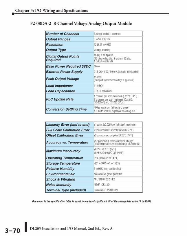
DL205 Installation and I/O Manual, 2nd Ed., Rev. A 3–70
Chapter 3: I/O Wiring and Specifications
F2-08DA-2 8-Channel Voltage Analog Output Module
Number of Channels 8, single-ended, 1 common
Output Ranges 0 to 5V, 0 to 10V
Resolution 12 bit (1 in 4096)
Output Type Voltage sourcing
Digital Output Points Required
16 (Y) output points(12 binary data bits, 3 channel ID bits, 1 output enable bit)
Base Power Required 5VDC 60mA
External Power Supply 21.6-26.4 VDC, 140 mA (outputs fully loaded)
Peak Output Voltage 15 VDC (clamped by transient voltage suppressor)
Load Impedance 1-10 kq
Load Capacitance 0.01 µF maximum
PLC Update Rate1 channel per scan maximum (D2-230 CPU)8 channels per scan maximum (D2-240, D2-250(-1) and D2-260 CPUs)
Conversion Settling Time 400µs maximum (full scale change)4.5 ms to 9ms for digital out to analog out
Linearity Error (end to end) ±1 count (±0.025% of full scale) maximum
Full Scale Calibration Error ±12 counts max. unipolar @ 25ºC (77ºF)
Offset Calibration Error ±3 counts max., unipolar @ 25ºC (77ºF)
Accuracy vs. Temperature ±57 ppm/ºC full scale calibration change (including maximum offset change of 2 counts)
Maximum Inaccuracy ±0.3% @ 25ºC (77ºF)±0.45% @ 0-60ºC (32-140ºF)
Operating Temperature 0º to 60ºC (32º to 140°F)
Storage Temperature -20º to 70ºC (-4º to 158ºF)
Relative Humidity 5 to 95% (non-condensing)
Environmental air No corrosive gases permitted
Shock & Vibration MIL STD 810C 514.2
Noise Immunity NEMA ICS3-304
Terminal Type (included) Removable; D2-8IOCON
One count in the specification table is equal to one least significant bit of the analog data value (1 in 4096).
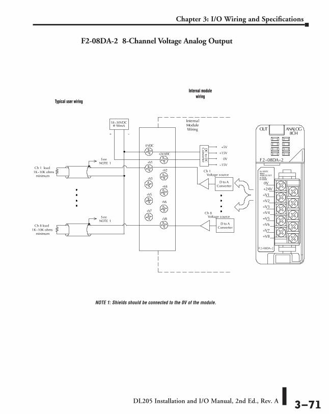
DL205 Installation and I/O Manual, 2nd Ed., Rev. A 3–71
Chapter 3: I/O Wiring and Specifications
F2-08DA-2 8-Channel Voltage Analog Output
InternalModuleWiring
+ --
18--30VDC
S ee
0VDC
+24VDC
+V5
+V7
+V8
NOTE 1 +V1
+V3
+V2
+V4
Voltage sourceCh 1
Ch 1 load1K--10K ohms
minimum
Voltage sourceCh 8
+24V
+V1
+V2
+V3
+V4
+V5
+V6
+V7
+V8
90mA
F2--08DA--2
OUT ANALOG
F2--08DA--2
8CH
ANALOGOUT0--5VDC
0V0--10VDC
DC
toD
CC
onverter
+5V
+15V
0V
--15V
D to AConverter
D to AConverter
+V6
S eeNOTE 1
Ch 8 load1K--10K ohms
minimum
18--30VDC
@ 90mA
Typical user wiring
Internal module wiring
NOTE 1: Shields should be connected to the 0V of the module.

DL205 Installation and I/O Manual, 2nd Ed., Rev. A 3–72
Chapter 3: I/O Wiring and Specifications
DL205 Combination Analog I/O ModulesF2-04AD2DA 4-Channel Analog Input / 2-Channel Analog Output Module
Number of Input Channels 4, single-ended (1 common)
Number of Output Channels 2, single-ended (1 common)
Ranges 4 to 20 mA current (current sinking)
Resolution 12 bit (1 in 4096)
Peak Withstanding Voltage 75VDC, current outputs
Max. Continuous Overload -40 to +40 mA, each current output
Input Impedance 250q, ±0.1%, 1/2 W, 25 ppm/ºC current input resistance
External Load Resistance 0q minimum, current outputs
Maximum Loop Supply 30VDC
Recommended Fuse 0.032 A, series 217 fast-acting, current inputs
Maximum Load/Power Supply910q /24V, current outputs620q /18V, 1200q /30V
Active Low-pass Filter -3 dB @ 20 Hz, 2 poles (-12 dB per octave)
Linearity Error (best fit) ±1 count (±0.025% of full scale) maximum
Output Settling Time 100 µs maximum (full scale change)
Accuracy vs. Temperature ±50 ppm/ºC full scale calibration change (including maximum offset change)
Maximum Inaccuracy ±0.1% @ 77ºF (25ºC)±0.3% @ 32 to 140ºF (0 to 60ºC)
Digital Input and Output Points Required
16 (X) input points (12 binary data bits, 2 channel ID bits, 2 diagnostic bits)16 (Y) output points (12 binary data bits, 2 channel enable bits)
PLC Update Rate
4 channels per scan maximum: (D2-240, D2-250(-1) and D2-260 CPUs)2 output channels per scan maximum: (D2-240, D2-250(-1) and D2-260 CPUs)1 input and 1 output channel per scan maximum: (D2-230 CPU)
Base Power Required 5VDC 90mA
External Power Supply Requirement
18-26.4 VDC @ 80mA 20mA per loop
Operating Temperature 32º to 140ºF (0º to 60ºC)
Storage Temperature -4º to 158ºF (-20º to 70ºC)
Relative Humidity 5 to 95% (non-condensing)
Environmental Air No corrosive gases permitted
Shock & Vibration MIL STD 810C 514.2
Noise Immunity NEMA ICS3-304
Terminal Type (included) Removable; D2-8IOCON
One count in the specification table is equal to one least significant bit of the analog data value (1 in 4096).
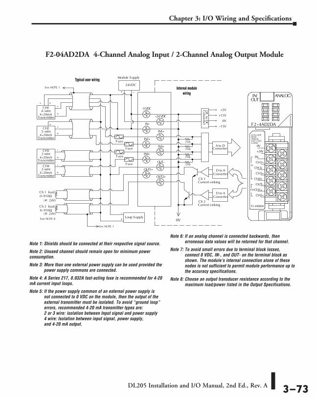
DL205 Installation and I/O Manual, 2nd Ed., Rev. A 3–73
Chapter 3: I/O Wiring and Specifications
F2-04AD2DA 4-Channel Analog Input / 2-Channel Analog Output Module
InternalModuleWiring
Ch 2 load0--910
0VDC
+24VDC
IN4+
OUT1+
OUT2+
OUT--
IN--
IN2+
IN1+
IN3+
Ch 1 load0--910
DC
toD
CC
onverter+5V
+15V
0V
--15V
CH14--wire
4--20mATransmitter
See NOTE 1
CH23--wire
4--20mATransmitter
CH32-wire
4--20mATransmitter
CH42-wire
4--20mATransmitter
+
--
+
--
+
--
+
---- +
+
+
--Loop S upply
0V
Current s inkingCh 1
Current s inkingCh 2
D to AConverter
D to AConverter
A to DConverter
250
250
250
250
0V
+24V
IN--
CH1+
CH 2+
CH3+
CH4+
OUT--
CH1+
CH2+
18 26.4 VDC80 mA
F2--4AD2DA
IN/ ANALOG
F2--4AD2DA
ANALOG4 IN/ 2 OUT
OUT
4--20mA
IN
OUT
24VDC
Module S upply
+ --
Fuse
Fuse
Fuse
Fuse
See NOTE 1
(@ 24V)
(@ 24V)
See NOTE 8
Typical user wiring
Internal module wiring
Note 1: Shields should be connected at their respective signal source.
Note 2: Unused channel should remain open for minimum power consumption.
Note 3: More than one external power supply can be used provided the power supply commons are connected.
Note 4: A Series 217, 0.032A fast-acting fuse is recommended for 4-20 mA current input loops.
Note 5: If the power supply common of an external power supply is not connected to 0 VDC on the module, then the output of the external transmitter must be isolated. To avoid “ground loop” errors, recommended 4-20 mA transmitter types are: 2 or 3 wire: isolation between Input signal and power supply 4 wire: Isolation between input signal, power supply, and 4-20 mA output.
Note 6: If an analog channel is connected backwards, then erroneous data values will be returned for that channel.
Note 7: To avoid small errors due to terminal block losses, connect 0 VDC, IN-, and OUT- on the terminal block as shown. The module’s internal connection alone of these nodes is not sufficient to permit module performance up to the accuracy specifications.
Note 8: Choose an output transducer resistance according to the maximum load/power listed in the Output Specifications.

DL205 Installation and I/O Manual, 2nd Ed., Rev. A 3–74
Chapter 3: I/O Wiring and Specifications
F2-08AD4DA-1 8-Channel Analog Current Input / 4-Channel Analog Current Output Module
Input Channels per Module 8, single ended (one common)
Input Range 0 to 20 mA
Resolution 12, 14, 16-bit selectable
External DC Power Required 100mA @ 18-26.4 VDC
Max. Continuous Overload ±45mA
Input Impedance 100 h 0.1% 1/4W
Filter Characteristics Active low pass, -3dB @ 80 Hz
Conversion Time12-bit = 1.5 ms per channel 14-bit = 6 ms per channel 16-bit = 25 ms per channel
Conversion Method Over sampling successive approximation
Accuracy vs. Temperature ±25 ppm / °C Max.
Maximum Inaccuracy 0.1% of range
Linearity Error (End to End)
12-bit = ±2 count max. (±0.06% of range) 14-bit = ±10 count max. (±0.06% of range) 16-bit = ±20 count max. (±0.06% of range) Monotonic with no missing codes
Full Scale Calibration Error (not including offset error) ±0.07% of range max.
Offset Calibration Error ±0.03% of range max.
Rec. Fuse (external) 0.032 A, Littelfuse Series 217 fast-acting
Base Power Required 5VDC 35mA
Output Channels per Module 4
Output Range 4 to 20 mA
Resolution 16-bit, 0.244 mA/bit
Output Type Current sourcing at 20 mA max.
Load Impedance 0-750 h
Max. Inaccuracy 0.25% of range
Max. Full Scale Calibration Error (not incl. offset error) ±0.075% of range max.
Max. Offset Calibration Error ±0.1% of range max.
Accuracy vs. Temperature ±25 ppm/ °C max. full scale calibration change (± 0.0025% of range / °C)
Max. Crosstalk at DC, 50/60Hz -70 dB, 1 LSB
NOT SUPPORTED BY D2-230 AND D2-240 CPUs.

DL205 Installation and I/O Manual, 2nd Ed., Rev. A 3–75
Chapter 3: I/O Wiring and Specifications
F2-08AD4DA-1 8-Channel Analog Current Input / 4-Channel Analog Current Output
shield, Channel 3
CH1 ADC
CH2 ADC
CH4 ADC
CH3 ADC
CH6 ADC
IN / ANALOG
F2-8AD4DA--1
0V
OUT2
OUT3
0V
IN2
IN3
0V
IN6
IN7
24V
OUT1
0V
OUT4
IN1
0V
IN4
IN5
IN8
0V
18--26.4VDC
8 IN 0--20mAANALOG@ 100 mA
4 OUT 4--20mA
OUT
AC or DC
4--20mA transmittershield, Channel 8transmitter
4--wire 4--20mA
See Note 2
CH8 ADC→ I8+ 100Ω
100Ω
CH7 ADC
COM
0.032A
4--20mA transmittershield, Channel 5transmitter
2--wire 4--20mA
→ I5+
Isolated analogcircuit common
4--20mA transmittertransmitter
3--wire 4--20mA
COM
+
100Ω
→ I3+100Ω
100Ω
100Ω
CH5 ADC
COM
Note 1: A Littlefuse Series 217, 0.032A fast--acting fuse is recommended for all 4--20mA current loop inputs.
Note 2: Connect shields to the 0V of the module; do not connect both ends of shield.
100Ω
100Ω
CH1 DAC
CH2 DAC
COMCH4 DAC
CH3 DAC
Isolated analogcircuit power
User 24VDCsupply
COM
24VDC+
0VDC--
← I1+
← I2+
← I3+← I4+
4--20mA outputChannel 2
--
4--20mA outputChannel 3
--
4--20mA outputChannel 4
--
4--20mA outputChannel 1--
See Note 2
Internal module wiring
Transmitter power
See Note 1
+
+
+
+
See Note 2
See Note 2
Linearity Error (End to End) ±1 count max. (±0.025% of full scale) Monotonic with no missing codes
Output Stability and Repeatability ±1 LSB after 10 min. warm-up typical
Output Ripple 0.005% of full scale
Output Settling Time 0.5 ms max., 5µs min. (full scale change)
Max. Continuous Overload Outputs open circuit protected
Type of Output Protection Electronically current limited to 20mA or less
Output Signal at Power-up and Power-down 4mA
Terminal Type (included) Removable; D2-16IOCON

DL205 Installation and I/O Manual, 2nd Ed., Rev. A 3–76
Chapter 3: I/O Wiring and Specifications
F2-08AD4DA-2 8-Channel Analog Voltage Input / 4-Channel Analog Voltage Output Module
Output Channels per Module 4
Output Range 0–5 V, 0–10 V
Resolution 0 to 5 V at 15-bit, 0 to10 V at 16-bit, 152µV /bit
Output Type Voltage sourcing/sinking at 10mA max.
Load Impedance >1000 h
Max. Inaccuracy 0.15% of range
Max. Full Scale Calibration Error (not incl. offset error)
±0.075% of range max.
Max. Offset Calibration Error ±0.025% of range max.
Accuracy vs. Temperature
±50 ppm/ °C max. full scale calibration change (± 0.005% of range / °C)
Max. Crosstalk @ DC, 50/60Hz -70 dB, 1 LSB
Input Channels per Module 8, single ended (one common)
Input Range 0 to 10 V
Resolution 12, 14, 16-bit selectable
External DC Power Required 80mA @ 18-26.4 VDC
Max. Continuous Overload ±100 V
Input Impedance >10Mh
Filter Characteristics Active low pass, -3 dB @ 80Hz
Conversion Time12-bit = 1.5 ms per channel 14-bit = 6 ms per channel 16-bit = 25 ms per channel
Conversion Method Over sampling successive approximation
Accuracy vs. Temperature ±50 ppm / °C Max.
Maximum Inaccuracy 0.1% of range
Linearity Error (End to End)
12-bit = ±1 count max. (±0.025% of range) 14-bit = ±4 count max. (±0.025% of range) 16-bit = ±16 count max. (±0.025% of range) Monotonic with no missing codes
Full Scale Calibration Error (not including offset error) ±0.075% of range max.
Offset Calibration Error ±0.025% of range max.
Base Power Required 5VDC 35mA

DL205 Installation and I/O Manual, 2nd Ed., Rev. A 3–77
Chapter 3: I/O Wiring and Specifications
F2-08AD4DA-2 8-Channel Analog Voltage Input / 4-Channel Analog Voltage Output
shield, Channel 3
CH1 ADC
CH2 ADC
CH4 ADC
CH3 ADC
CH6 ADC
IN / ANALOG
F2-8AD4DA--2
0V
OUT2
OUT3
0V
IN2
IN3
0V
IN6
IN7
24V
OUT1
0V
OUT4
IN1
0V
IN4
IN5
IN8
0V
18--26.4V
4 OUTPUTS0--10V8 INPUTS
0--5/0--10V
OUT
AC or DC
Voltage transmittershield, Channel 8transmitter
4--wire voltage
See Note 1
CH8 ADCV8+
CH7 ADC
COMVoltage transmittershield, Channel 5transmitter
2--wire voltage
V5+
Isolated analogcircuit common
Voltage transmittertransmitter
3--wire voltage
COM
+V3+
CH5 ADC
COM
Note 1: Connect shields to the 0V of the module; do not connect both ends of shield.
CH1 DAC
CH2 DAC
COMCH4 DAC
CH3 DAC
Isolated analogcircuit power
User 24VDCsupply
COM
24VDC+
0VDC--
V1+
V2+
V3+V4+
Voltage outputChannel 2
--
Voltage outputChannel 3--
Voltage outputChannel 4
--
Voltage outputChannel 1--
See Note 1
Internal module wiring
Transmitter power
+
+
+
+
See Note 1
See Note 1
80mA
Linearity Error (End to End)
±1 count max. (±0.025% of full scale) Monotonic with no missing codes
Output Stability and Repeatability ±1 LSB after 10 min. warm-up typical
Output Ripple 0.005% of full scale
Output Settling Time 0.5 ms max., 5µs min. (full scale change)
Max. Continuous Overload Outputs current limited to 15mA typical
Type of Output Protection
1VDC peak output voltage (clamped by transient voltage suppressor)
Output Signal at Power-up and Power-down
0V
Terminal Type (included) Removable; D2-16IOCON

DL205 Installation and I/O Manual, 2nd Ed., Rev. A 3–78
Chapter 3: I/O Wiring and Specifications
Glossary of Specification Terms Inputs or Outputs Per Module
Indicates number of input or output points per module and designates current sinking, current sourcing, or either.
Commons Per ModuleNumber of commons per module and their electrical characteristics.
Input Voltage RangeThe operating voltage range of the input circuit.
Output Voltage RangeThe operating voltage range of the output circuit.
Peak VoltageMaximum voltage allowed for the input circuit.
AC FrequencyAC modules are designed to operate within a specific frequency range.
ON Voltage LevelThe voltage level at which the input point will turn ON.
OFF Voltage LevelThe voltage level at which the input point will turn OFF.
Input impedanceInput impedance can be used to calculate input current for a particular operating voltage.
Input CurrentTypical operating current for an active (ON) input.
Minimum ON CurrentThe minimum current for the input circuit to operate reliably in the ON state.
Maximum OFF CurrentThe maximum current for the input circuit to operate reliably in the OFF state.
Minimum LoadThe minimum load current for the output circuit to operate properly.
External DC RequiredSome output modules require external power for the output circuitry.
ON Voltage DropSometimes called “saturation voltage”, it is the voltage measured from an output point to its common terminal when the output is ON at max. load.
DL205 Installation and I/O Manual, 2nd Ed., Rev. A 3–79
Chapter 3: I/O Wiring and Specifications
Maximum Leakage CurrentThe maximum current a connected maximum load will receive when the output point is OFF.
Maximum Inrush CurrentThe maximum current used by a load for a short duration upon an OFF to ON transition of a output point. It is greater than the normal ON state current and is characteristic of inductive loads in AC circuits.
Base Power RequiredPower from the base power supply is used by the DL205 input modules and varies between different modules. The guidelines for using module power is explained in the power budget configuration section in Chapter 4–7.
OFF to ON ResponseThe time the module requires to process an OFF to ON state transition.
ON to OFF ResponseThe time the module requires to process an ON to OFF state transition.
Terminal TypeIndicates whether the terminal type is a removable or non-removable connector or a terminal.
Status IndicatorsThe LEDs that indicate the ON/OFF status of an input point. These LEDs are electrically located on either the logic side or the field device side of the input circuit.
FusesProtective devices for an output circuit, which stop current flow when current exceeds the fuse rating. They may be replaceable or non–replaceable, or located externally or internally.

EuropEan union DirEctivEs (cE)
AppendixAppendixAppendix
AAIn This Appendix...
European Union (EU) Directives ............................................................................... A-2
Basic EMC Installation Guidelines ............................................................................. A-4

DL205 Installation and I/O Manual, 2nd Ed., Rev. A A-2
Appendix A: European Union Directives (CE)
European Union (EU) DirectivesNOTE: The information contained in this section is intended as a guideline and is based on our interpretation of the various standards and requirements. Since the actual standards are issued by other parties, and in some cases governmental agencies, the requirements can change over time without advance warning or notice. Changes or additions to the standards can possibly invalidate any part of the information provided in this section.
This area of certification and approval is absolutely vital to anyone who wants to do business in Europe. One of the key tasks that faced the EU member countries and the European Economic Area (EEA) was the requirement to bring several similar yet distinct standards together into one common standard for all members. The primary purpose of a single standard was to make it easier to sell and transport goods between the various countries and to maintain a safe working and living environment. The Directives that resulted from this merging of standards are now legal requirements for doing business in Europe. Products that meet these Directives are required to have a CE mark to signify compliance.
Member CountriesAs of January 1, 2007, the members of the EU are Austria, Belgium, Bulgaria, Cyprus, Czech Republic, Denmark, Estonia, Finland, France, Germany, Greece, Hungary, Ireland, Italy, Latvia, Lithonia, Luxembourg, Malta, Netherlands, Poland, Portugal, Romania, Slovakia, Slovenia, Spain, Sweden, and United Kingdom. Iceland, Liechtenstein, and Norway together with the EU members make up the European Economic Area (EEA) and all are covered by the Directives.
Applicable DirectivesThere are several Directives that apply to our products. Directives may be amended, or added, as required.
• Electromagnetic Compatibility Directive (EMC) — this Directive attempts to ensure that devices, equipment, and systems have the ability to function satisfactorily in an electromagnetic environment without introducing intolerable electromagnetic disturbance to anything in that environment.
• Machinery Safety Directive — this Directive covers the safety aspects of the equipment, installation, etc. There are several areas involved, including testing standards covering both electrical noise immunity and noise generation.
• Low Voltage Directive — this Directive is also safety related and covers electrical equipment that has voltage ranges of 50–1000VAC and/or 75–1500VDC.
• Battery Directive — this Directive covers the production, recycling, and disposal of batteries.
ComplianceCertain standards within each Directive already require mandatory compliance. The EMC Directive, which has gained the most attention, became mandatory as of January 1, 1996. The Low Voltage Directive became mandatory as of January 1, 1997.
Ultimately, we are all responsible for our various pieces of the puzzle. As manufacturers, we must test our products and document any test results and/or installation procedures that are necessary to comply with the Directives. As a machine builder, you are responsible for

DL205 Installation and I/O Manual, 2nd Ed., Rev. A A-3
Appendix A: European Union Directives (CE)
installing the products in a manner which will ensure compliance is maintained. You are also responsible for testing any combinations of products that may (or may not) comply with the Directives when used together. The end user of the products must comply with any Directives that may cover maintenance, disposal, etc. of equipment or various components. Although we strive to provide the best assistance available, it is impossible for us to test all possible configurations of our products with respect to any specific Directive. Because of this, it is ultimately your responsibility to ensure that your machinery (as a whole) complies with these Directives and to keep up with applicable Directives and/or practices that are required for compliance.
As of January 1, 1999, the DL05, DL06, DL205, DL305, and DL405 PLC systems manufactured by Koyo Electronics Industries, FACTS Engineering or HOST Engineering, when properly installed and used, conform to the Electromagnetic Compatibility (EMC), Low Voltage Directive, and Machinery Directive requirements of the following standards.
• EMC Directive Standards Relevant to PLCs EN50081–1 Generic emission standard for residential, commercial, and light industry EN50081–2 Generic emission standard for industrial environment. EN50082–1 Generic immunity standard for residential, commercial, and light industry EN50082–2 Generic immunity standard for industrial environment.
• Low Voltage Directive Standards Applicable to PLCs EN61010–1 Safety requirements for electrical equipment for measurement, control, and laboratory use.
• Product Specific Standard for PLCs EN61131–2 Programmable controllers, equipment requirements and tests. This standard replaces the above generic standards for immunity and safety. However, the generic emissions standards must still be used in conjunction with the following standards: -EN 61000-3-2 Harmonics -EN 61000-3-2 Fluctuations
• Warning on Electrostatic Discharge (ESD) We recommend that all personnel take necessary precautions to avoid the risk of transferring static charges to inside the control cabinet, and clear warnings and instructions should be provided on the cabinet exterior. Such precautions may include, the use of earth straps, similar devices or the powering off of the equipment inside the enclosure before the door is opened.
• Warning on Radio Interference (RFI) This is a class A product. In a domestic environment this product may cause radio interference in which case the user may be required to take adequate measures.
General Safety• External switches, circuit breaker or external fusing, are required for these devices.
• The switch or circuit breaker should be mounted near the PLC equipment.
AutomationDirect is currently in the process of changing their testing procedures from the generic standards to the product specific standards.

DL205 Installation and I/O Manual, 2nd Ed., Rev. A A-4
Appendix A: European Union Directives (CE)
Special Installation ManualThe installation requirements to comply with the requirements of the Machinery Directive, EMC Directive and Low Voltage Directive are slightly more complex than the normal installation requirements found in the United States. To help with this, we have published a special manual which you can order:
• DA–EU–M – EU Installation Manual that covers special installation requirements to meet the EU Directive requirements. Order this manual to obtain the most up-to-date information.
Other Sources of InformationAlthough the EMC Directive gets the most attention, other basic Directives, such as the Machinery Directive and the Low Voltage Directive, also place restrictions on the control panel builder. Because of these additional requirements it is recommended that the following publications be purchased and used as guidelines:
• BSI publication TH 42073: February 1996 – covers the safety and electrical aspects of the Machinery Directive
• EN 60204–1:1992 – General electrical requirements for machinery, including Low Voltage and EMC considerations
• IEC 1000–5–2: EMC earth grounding and cabling requirements
• IEC 1000–5–1: EMC general considerations
It may be possible for you to obtain this information locally; however, the official source of applicable Directives and related standards is:
The Office for Official Publications of the European Communities L–2985 Luxembourg; quickest contact is via the World Wide Web at http://publications.europa.eu/index_en.htm
Other sources are:
British Standards Institution – Sales Department Linford Wood Milton Keynes MK14 6LE United Kingdom; the quickest contact is via the World Wide Web at http://www.bsi.org.uk A commercial provider of Standards at www.ihs.com
Basic EMC Installation GuidelinesEnclosures
The simplest way to meet the safety requirements of the Machinery and Low Voltage Directives is to house all control equipment in an industry standard lockable steel enclosure. This normally has an added benefit because it will also help ensure that the EMC characteristics are well within the requirements of the EMC Directive. Although the RF emissions from the PLC equipment, when measured in the open air, are well below the EMC Directive limits, certain configurations can increase emission levels. Holes in the enclosure, for the passage of cables or to mount operator interfaces, will often increase emissions.

DL205 Installation and I/O Manual, 2nd Ed., Rev. A A-5
Appendix A: European Union Directives (CE)
AC Mains FiltersThe DL205 AC powered base power supplies require extra mains filtering to comply with the EMC Directive on conducted RF emissions. All PLC equipment has been tested with filters from Schaffner, which reduce emissions levels if the filters are properly grounded (earth ground). A filter with a current rating suitable to supply all PLC power supplies and AC input modules should be selected. We suggest the FN2010 for DL205 systems.
NOTE: Very few mains filters can reduce problem emissions to negligible levels. In some cases, filters may increase conducted emissions if not properly matched to the problem emissions.
Mains fused
isolation transformer
*Mains filter
Mains
disconnect switch
*Ferrite choke
on I/O wiring
I/O common
earthed
Earth
ground
*Ferrite choke on
communications cables
Metallic conduit for
communications
and I/O wiring
Communications
keyed lockout
switch
Star Washers
PanelGround BraidCopper Lugs
Panel orSingle Point
Ground
*may be required for CE compliance(see Declaration of Conformity forspecific product requirements).
Star Washers
Illustrations are not to scaleLock Nut
Lock Nut
Transient voltage
suppressor

DL205 Installation and I/O Manual, 2nd Ed., Rev. A A-6
Appendix A: European Union Directives (CE)
Suppression and FusingIn order to comply with the fire risk requirements of the Low Voltage and Machinery Directive electrical standards (EN 61010–1 and EN 60204–1), by limiting the power into “unlimited” mains circuits with power leads reversed, it is necessary to fuse both AC and DC supply inputs. You should also install a transient voltage suppressor across the power input connections of the PLC. Choose a suppressor such as a metal oxide varistor, with a rating of 275VAC working voltage for 230V nominal supplies (150VAC working voltage for 115V supplies) and high energy capacity (e.g., 140 joules).
Transient suppressors must be protected by fuses and the capacity of the transient suppressor must be greater than the blow characteristics of the fuses or circuit breakers to avoid a fire risk. A recommended AC supply input arrangement for Koyo PLCs is to use twin 3 amp TT fused terminals with fuse blown indication, such as DINnectors DN–F10L terminals, or twin circuit breakers, wired to a Schaffner FN2010 filter or equivalent, with high energy transient suppressor soldered directly across the output terminals of the filter. PLC system inputs should also be protected from voltage impulses by deriving their power from the same fused, filtered, and surge-suppressed supply.
Internal Enclosure GroundingA heavy-duty star earth terminal block should be provided in every cubicle for the connection of all earth ground straps, protective earth ground connections, mains filter earth ground wires, and mechanical assembly earth ground connections. This should be installed to comply with safety and EMC requirements, local standards, and the requirements found in IEC 1000–5–2.The Machinery Directive also requires that the common terminals of PLC input modules, and common supply side of loads driven from PLC output modules should be connected to the protective earth ground terminal.
Equipotential Grounding
Adequate site earth grounding must be provided for equipment containing modern electronic circuitry. The use of isolated earth electrodes for electronic systems is forbidden in some countries. Make sure you check any requirements for your particular destination. IEC 1000–5–2 covers equipotential bonding of earth grids adequately, but special attention should be given to apparatus and control cubicles that contain I/O devices, remote I/O racks, or have inter-system communications with the primary PLC system enclosure. An equipotential bond wire must be provided alongside all serial communications cables, and to any separate items of the plant which contain I/O devices connected to the PLC. The diagram shows an example of four physical locations connected by a communications cable.
Serial Communication CableEqui-potential BondKey

DL205 Installation and I/O Manual, 2nd Ed., Rev. A A-7
Appendix A: European Union Directives (CE)
Communications and Shielded CablesGood quality 24 AWG minimum twisted-pair shielded cables, with overall foil and braid shields are recommended for analog cabling and communications cabling outside of the PLC enclosure. To date it has been a common practice to only provide an earth ground for one end of the cable shield in order to minimize the risk of noise caused by earth ground loop currents between apparatus. The procedure of only grounding one end, which primarily originated as a result of trying to reduce hum in audio systems, is no longer applicable to the complex industrial environment. Shielded cables are also efficient emitters of RF noise from the PLC system, and can interact in a parasitic manner in networks and between multiple sources of interference.
The recommendation is to use shielded cables as electrostatic “pipes” between apparatus and systems, and to run heavy gauge equi-potential bond wires alongside all shielded cables. When a shielded cable runs through the metallic wall of an enclosure or machine, it is recommended in IEC 1000–5–2 that the shield should be connected over its full perimeter to the wall, preferably using a conducting adapter, and not via a pigtail wire connection to an earth ground bolt. Shields must be connected to every enclosure wall or machine cover that they pass through.
Analog and RS232 CablesProviding an earth ground for both ends of the shield for analog circuits provides the perfect electrical environment for the twisted pair cable as the loop consists of signal and return, in a perfectly balanced circuit arrangement, with connection to the common of the input circuitry made at the module terminals. RS232 cables are handled in the same way.
Multidrop CablesRS422 twin twisted pair, and RS485 single twisted pair cables also require a 0V link, which has often been provided in the past by the cable shield. It is now recommended that you use triple twisted pair cabling for RS422 links, and twin twisted pair cable for RS485 links. This is because the extra pair can be used as the 0V inter-system link. With loop DC power supplies earth grounded in both systems, earth loops are created in this manner via the inter-system 0V link. The installation guides encourage earth loops, which are maintained at a low impedance by using heavy equipotential bond wires. To account for non–European installations using single-end earth grounds, and sites with far
ScreenedCable
Equi-potentialBond
Control Cubicle
To EarthBlock
ConductiveAdapter
SerialI/O

DL205 Installation and I/O Manual, 2nd Ed., Rev. A A-8
Appendix A: European Union Directives (CE)
from ideal earth ground characteristics, we recommend the addition of 100 ohm resistors at each 0V link connection in network and communications cables.
Shielded Cables within EnclosuresWhen you run cables between PLC items within an enclosure which also contains susceptible electronic equipment from other manufacturers, remember that these cables may be a source of RF emissions. There are ways to minimize this risk. Standard data cables connecting PLCs and/or operator interfaces should be routed well away from other equipment and their associated cabling. You can make special serial cables where the cable shield is connected to the enclosure’s earth ground at both ends, the same way as external cables are connected.
Analog Modules and RF InterferenceAll Automationdirect products are tested to withstand field strength levels up to 10V/m, which is the maximum required by the relevant EU standards. While all products pass this test, analog modules will typically exhibit deviations of their readings. This is quite normal; however, systems designers should be aware of this and plan accordingly.
When assembling a control system using analog modules, these issues must be adhered to and should be integrated into the system design. This is the responsibility of the system builder/commissioner.
Network IsolationFor safety reasons, it is a specific requirement of the Machinery Directive that a keyswitch that isolates any network input signal during maintenance must be provided, so that remote commands cannot be received that could result in the operation of the machinery. The FA–ISOCON does not have a keyswitch! Use a keylock and switch on your enclosure, which, when open, removes power from the FA–ISOCON. To avoid the introduction of noise into the system, any keyswitch assembly should be housed in its own earth grounded steel box and the integrity of the shielded cable must be maintained.
Again, for further information on EU directives we recommend that you get a copy of our EU Installation Manual (DA–EU–M). Also, if you are connected to the World Wide Web, you can check the EU Commission’s official site at: http://ec.europa.eu/index_en.htm.
DC Powered VersionsDue to slightly higher emissions radiated by the DC powered versions of the DL205, and the differing emissions performance for different DC supply voltages, the following stipulations must be met:
• The PLC must be housed within a metallic enclosure with a minimum amount of orifices.
• I/O and communications cabling exiting the cabinet must be contained within metallic conduit/trunking.
RXDMaster
RXDTXD 0V+ – + –
Slave nTXD 0V
+ – + –
Last SlaveRXD TXD0V+ – + –
Termination
100 100
Termination
100
DL205 Installation and I/O Manual, 2nd Ed., Rev. A A-9
Appendix A: European Union Directives (CE)
Items Specific to the DL205• The rating between all circuits in this product are rated as basic insulation only, as appropriate for
single fault conditions.
• There is no isolation offered between the PLC and the analog inputs of this product.
• It is the responsibility of the system designer to earth one side of all control and power circuits, and to earth the braid of screened cables.
• This equipment must be properly installed while adhering to the guidelines of the installation manual DA–EU–M (available for download at AutomationDirect Technical Support Manuals), and the installation standards IEC 1000–5–1, IEC 1000–5–2 and IEC 1131–4.
• It is a requirement that all PLC equipment must be housed in a protective steel enclosure, which limits access to operators by a lock and power breaker. If access is required by operators or untrained personnel, the equipment must be installed inside an internal cover or secondary enclosure. A warning label must be used on the front door of the installation cabinet as follows: Warning: Exposed terminals and hazardous voltages inside.
• It should be noted that the safety requirements of the machinery directive standard EN60204–1 state that all equipment power circuits must be wired through isolation transformers or isolating power supplies, and that one side of all AC or DC control circuits must be earthed.
• Both power input connections to the PLC must be separately fused using 3 amp T-type anti–surge fuses, and a transient suppressor fitted to limit supply overvoltages.
• The user is made aware by notice in the documentation that, if the equipment is used in a manner not specified by the manufacturer, the protection provided by the equipment may be impaired.


