EECC551 - ShaabanEECC551 - Shaaban#1 Lec # 2 Winter 2001 12-5-2001
DLX Instruction FormatDLX Instruction Format16 bits6 bits 5 bits 5 bits
Immediaterdrs1Opcode
6 bits 5 bits 5 bits 5 bits 11 bits
Opcode rs1 rs2 rd func
6 bits 26 bits
Opcode Offset added to PC
Jump and jump and link. Trap and return from exception
Register-register ALU operations: rd ←← rs1 func rs2 Function encodes the data path operation: Add, Sub .. Read/write special registers and moves.
Encodes: Loads and stores of bytes, words, half words. All immediates (rd ← ← rs1 op immediate)Conditional branch instructions (rs1 is register, rd unused)Jump register, jump and link register (rd = 0, rs = destination, immediate = 0)
J - Type instruction
R - type instruction
I - type instruction
0 5 6 10 11 15 16 31
0 5 6 10 11 15 16 20 31
0 5 6 31
EECC551 - ShaabanEECC551 - Shaaban#2 Lec # 2 Winter 2001 12-5-2001
A Basic Multi-CycleA Basic Multi-CycleImplementation of DLXImplementation of DLX
• Every integer DLX instruction can be implemented in atmost five clock cycles:
1 Instruction fetch cycle (IF):
IR ← Mem[PC]NPC ← PC + 4
2 Instruction decode/register fetch cycle (ID):
A ← Regs[IR6..10];B ← Regs[IR 11..15];Imm ← ((IR16)16##IR 16..31)
Note: IR (instruction register), NPC (next sequential program counter register)
A, B, Imm are temporary registers
EECC551 - ShaabanEECC551 - Shaaban#3 Lec # 2 Winter 2001 12-5-2001
A Basic Implementation of DLX (continued)A Basic Implementation of DLX (continued)
3 Execution/Effective address cycle (EX):
– Memory reference:
ALUOutput ← A + Imm;
– Register-Register ALU instruction:
ALUOutput ← A func B;
– Register-Immediate ALU instruction:
ALUOutput ← A op Imm;
– Branch:
ALUOutput NPC + Imm;Cond ← (A op 0)
EECC551 - ShaabanEECC551 - Shaaban#4 Lec # 2 Winter 2001 12-5-2001
A Basic Implementation of DLX (continued)A Basic Implementation of DLX (continued)
4 Memory access/branch completion cycle (MEM):
– Memory reference:
LMD ← Mem[ALUOutput] orMem[ALUOutput] ← B;
– Branch:
if (cond) PC ← ALUOutput else PC ← NPC
Note: LMD (load memory data) register
EECC551 - ShaabanEECC551 - Shaaban#5 Lec # 2 Winter 2001 12-5-2001
A Basic Implementation of DLX (continued)A Basic Implementation of DLX (continued)
5 Write-back cycle (WB):
– Register-Register ALU instruction:
Regs[IR 16..20] ← ALUOutput;
– Register-Immediate ALU instruction:
Regs[IR 11..15] ← ALUOutput;
– Load instruction:
Regs[IR 11..15] ← LMD;
Note: LMD (load memory data) register
EECC551 - ShaabanEECC551 - Shaaban#6 Lec # 2 Winter 2001 12-5-2001
A Multi-Cycle A Multi-Cycle DLX DatapathDLX DatapathImplementationImplementation
EECC551 - ShaabanEECC551 - Shaaban#7 Lec # 2 Winter 2001 12-5-2001
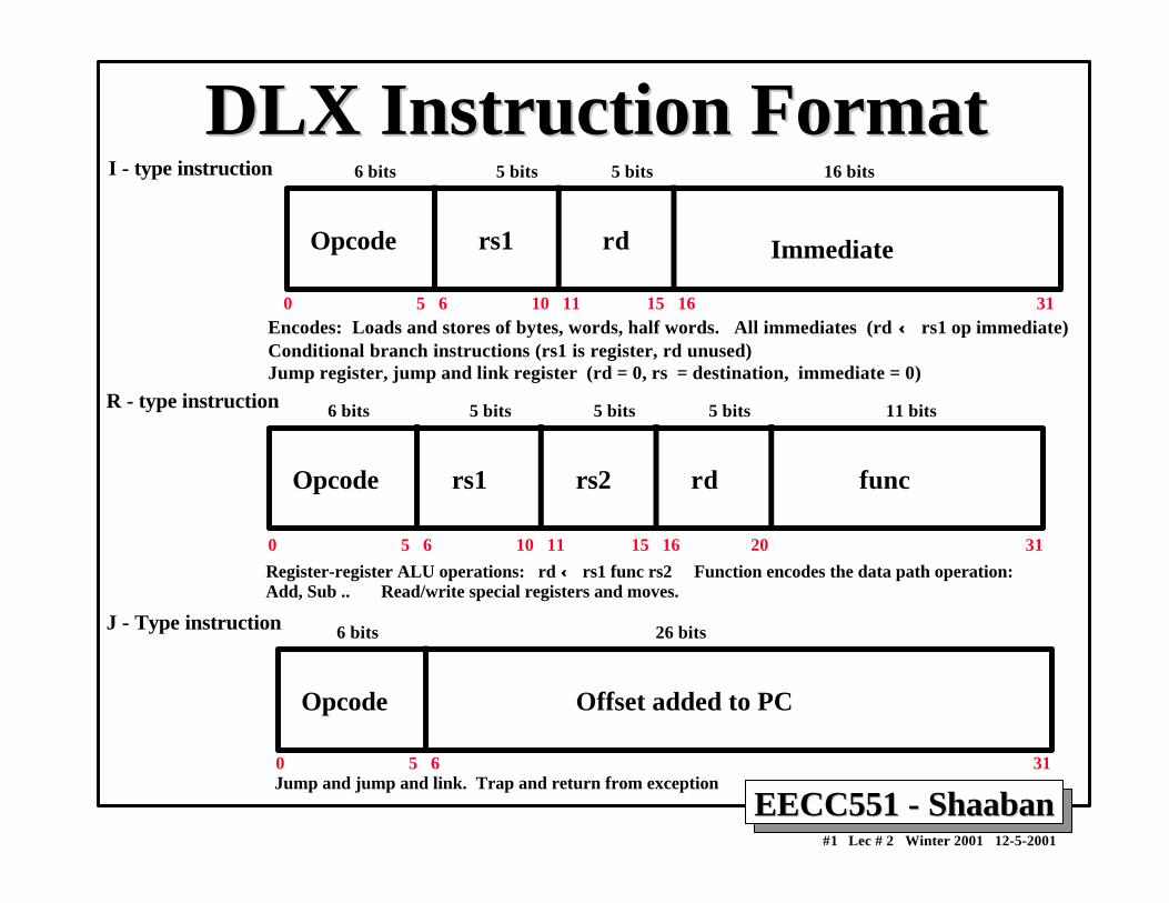
Pipelining: DefinitionsPipelining: Definitions• Pipelining is an implementation technique where multiple
operations on a number of instructions are overlapped inexecution.
• An instruction execution pipeline involves a number ofsteps, where each step completes a part of an instruction.
• Each step is called a pipe stage or a pipe segment.
• The stages or steps are connected one to the next to form apipe -- instructions enter at one end and progress throughthe stage and exit at the other end.
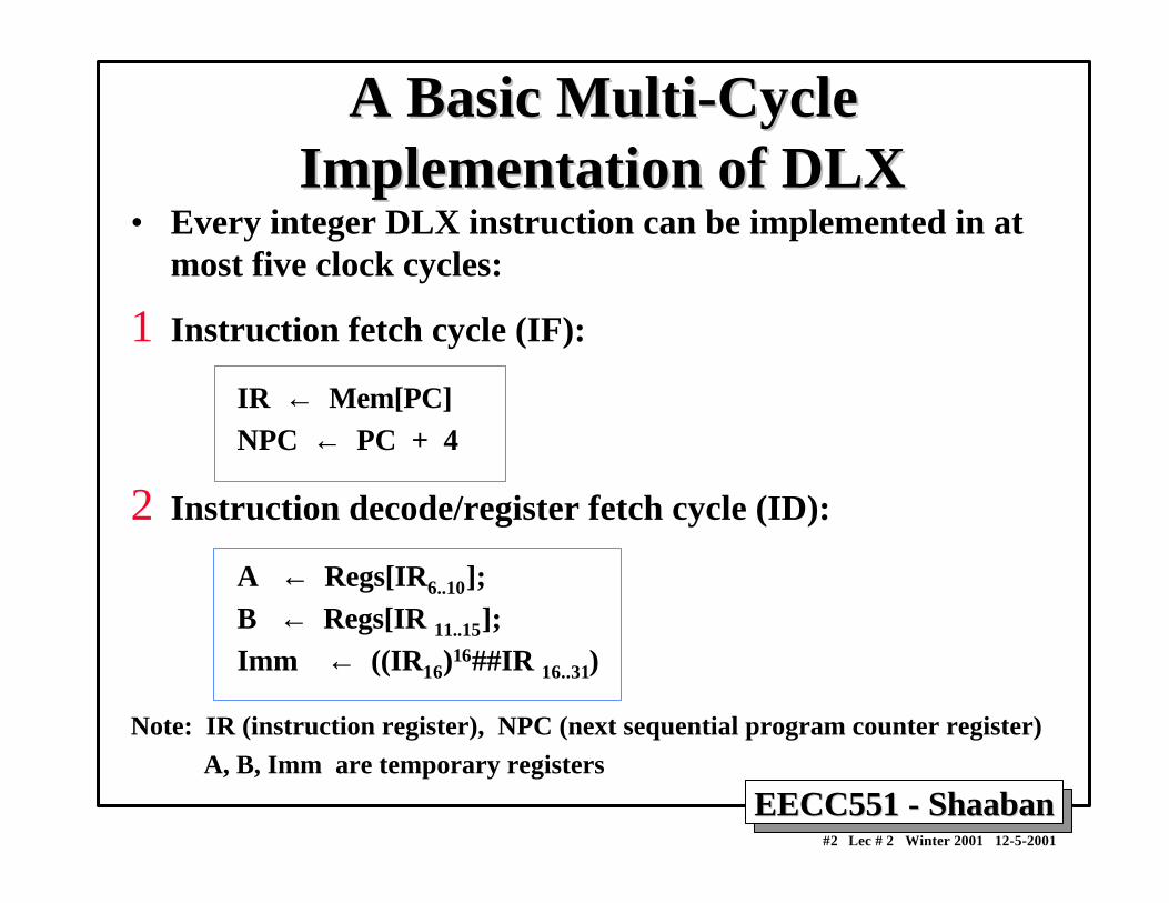
• Throughput of an instruction pipeline is determined byhow often an instruction exists the pipeline.
• The time to move an instruction one step down the line is isequal to the machine cycle and is determined by the stagewith the longest processing delay.
EECC551 - ShaabanEECC551 - Shaaban#8 Lec # 2 Winter 2001 12-5-2001
Pipelining: Design GoalsPipelining: Design Goals• The length of a machine clock cycle is determined by the
time required for the slowest pipe stage.
• An important pipeline design consideration is to balance thelength of each pipeline stage.
• If all stages are perfectly balanced, then the time perinstruction on a pipelined machine (assuming idealconditions with no stalls):
Time per instruction on unpipelined machine
Number of pipe stages
• Under these ideal conditions:
– Speedup from pipelining equals the number of pipeline stages: n,
– One instruction is completed every cycle, CPI = 1 .
EECC551 - ShaabanEECC551 - Shaaban#9 Lec # 2 Winter 2001 12-5-2001
Simple DLX PipelinedSimple DLX PipelinedInstruction ProcessingInstruction Processing
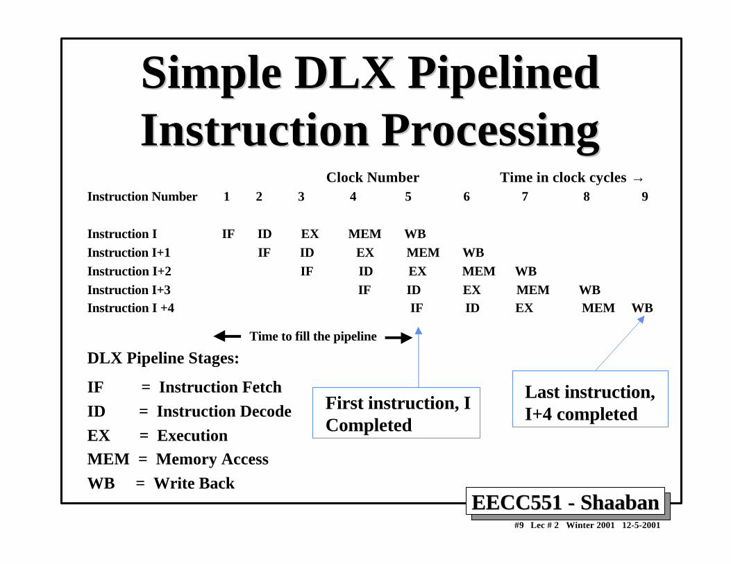
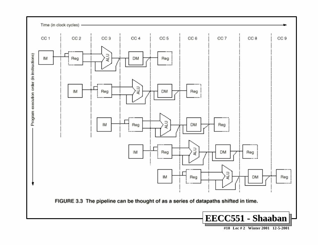
Clock Number Time in clock cycles →Instruction Number 1 2 3 4 5 6 7 8 9
Instruction I IF ID EX MEM WBInstruction I+1 IF ID EX MEM WBInstruction I+2 IF ID EX MEM WBInstruction I+3 IF ID EX MEM WBInstruction I +4 IF ID EX MEM WB
Time to fill the pipeline
DLX Pipeline Stages:
IF = Instruction Fetch
ID = Instruction Decode
EX = ExecutionMEM = Memory Access
WB = Write Back
First instruction, ICompleted
Last instruction, I+4 completed
EECC551 - ShaabanEECC551 - Shaaban#11 Lec # 2 Winter 2001 12-5-2001
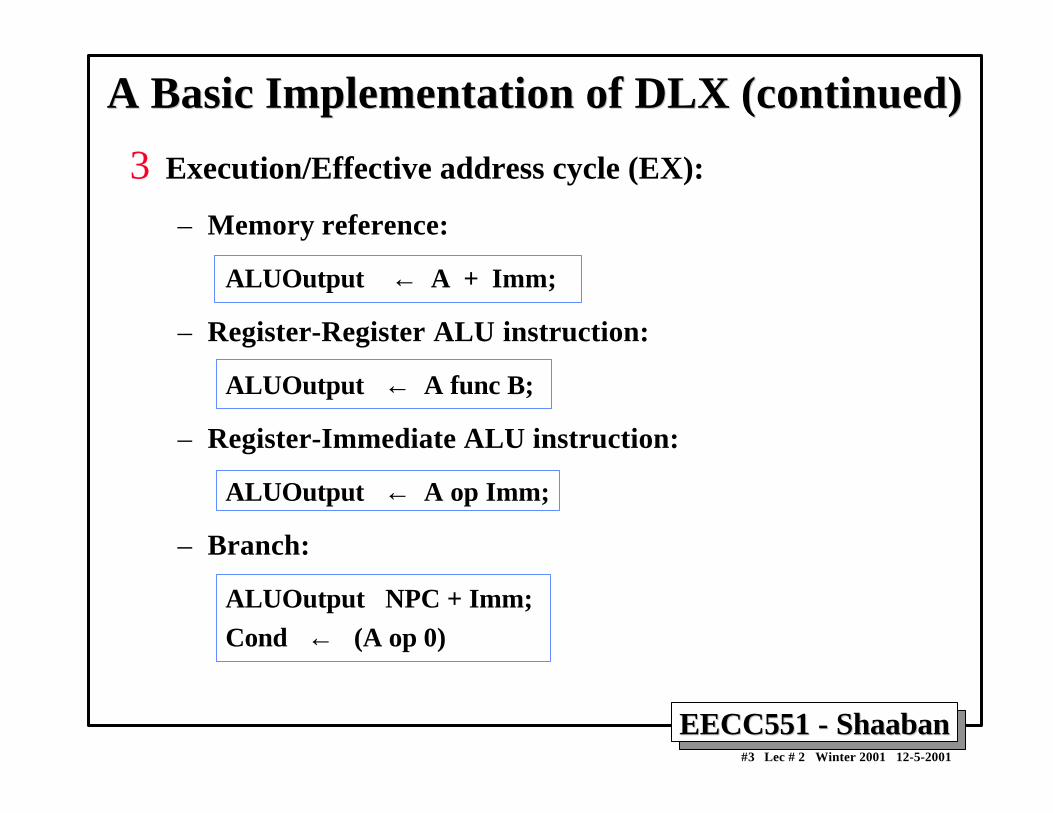
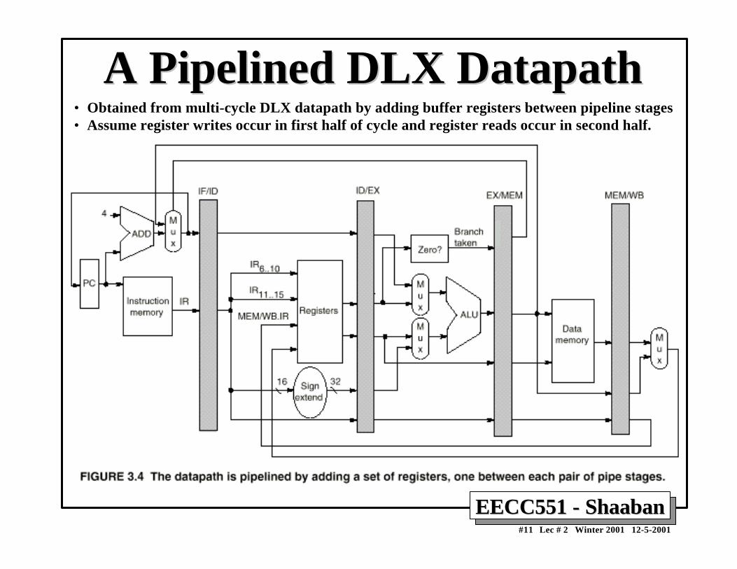
A Pipelined DLX DatapathA Pipelined DLX Datapath• Obtained from multi-cycle DLX datapath by adding buffer registers between pipeline stages• Assume register writes occur in first half of cycle and register reads occur in second half.
EECC551 - ShaabanEECC551 - Shaaban#13 Lec # 2 Winter 2001 12-5-2001
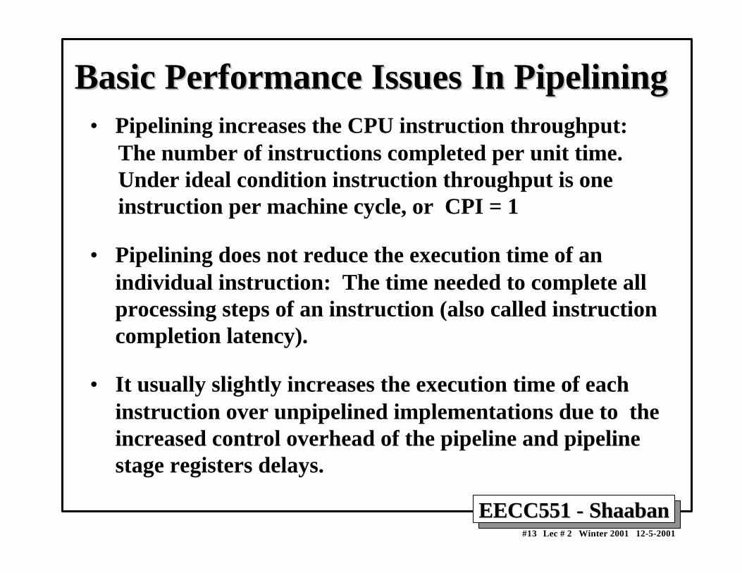
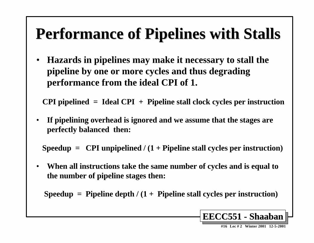
Basic Performance Issues In PipeliningBasic Performance Issues In Pipelining• Pipelining increases the CPU instruction throughput: The number of instructions completed per unit time. Under ideal condition instruction throughput is one instruction per machine cycle, or CPI = 1
• Pipelining does not reduce the execution time of anindividual instruction: The time needed to complete allprocessing steps of an instruction (also called instructioncompletion latency).
• It usually slightly increases the execution time of eachinstruction over unpipelined implementations due to theincreased control overhead of the pipeline and pipelinestage registers delays.
EECC551 - ShaabanEECC551 - Shaaban#14 Lec # 2 Winter 2001 12-5-2001
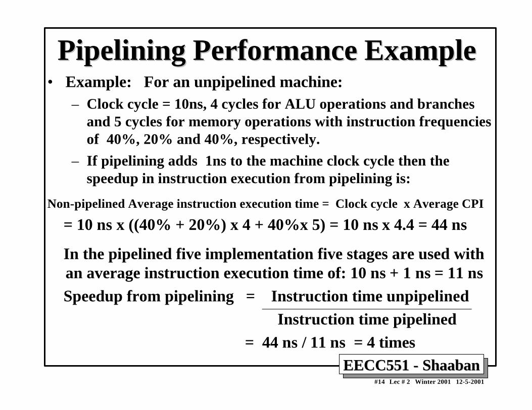
Pipelining Performance ExamplePipelining Performance Example• Example: For an unpipelined machine:
– Clock cycle = 10ns, 4 cycles for ALU operations and branchesand 5 cycles for memory operations with instruction frequenciesof 40%, 20% and 40%, respectively.
– If pipelining adds 1ns to the machine clock cycle then thespeedup in instruction execution from pipelining is:
Non-pipelined Average instruction execution time = Clock cycle x Average CPI
= 10 ns x ((40% + 20%) x 4 + 40%x 5) = 10 ns x 4.4 = 44 ns
In the pipelined five implementation five stages are used withan average instruction execution time of: 10 ns + 1 ns = 11 ns
Speedup from pipelining = Instruction time unpipelined Instruction time pipelined = 44 ns / 11 ns = 4 times
EECC551 - ShaabanEECC551 - Shaaban#15 Lec # 2 Winter 2001 12-5-2001
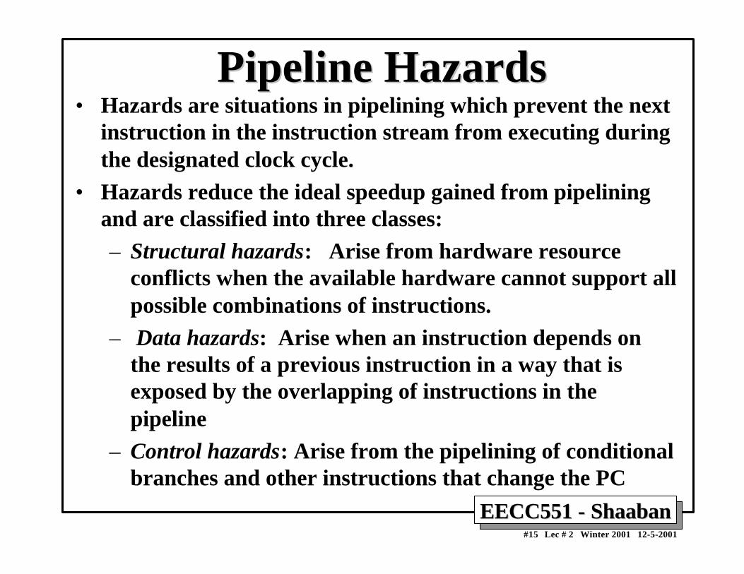
Pipeline HazardsPipeline Hazards• Hazards are situations in pipelining which prevent the next
instruction in the instruction stream from executing duringthe designated clock cycle.
• Hazards reduce the ideal speedup gained from pipeliningand are classified into three classes:– Structural hazards: Arise from hardware resource
conflicts when the available hardware cannot support allpossible combinations of instructions.
– Data hazards: Arise when an instruction depends onthe results of a previous instruction in a way that isexposed by the overlapping of instructions in thepipeline
– Control hazards: Arise from the pipelining of conditionalbranches and other instructions that change the PC
EECC551 - ShaabanEECC551 - Shaaban#16 Lec # 2 Winter 2001 12-5-2001
Performance of Pipelines with StallsPerformance of Pipelines with Stalls
• Hazards in pipelines may make it necessary to stall thepipeline by one or more cycles and thus degradingperformance from the ideal CPI of 1.
CPI pipelined = Ideal CPI + Pipeline stall clock cycles per instruction
• If pipelining overhead is ignored and we assume that the stages areperfectly balanced then:
Speedup = CPI unpipelined / (1 + Pipeline stall cycles per instruction)
• When all instructions take the same number of cycles and is equal tothe number of pipeline stages then:
Speedup = Pipeline depth / (1 + Pipeline stall cycles per instruction)
EECC551 - ShaabanEECC551 - Shaaban#17 Lec # 2 Winter 2001 12-5-2001
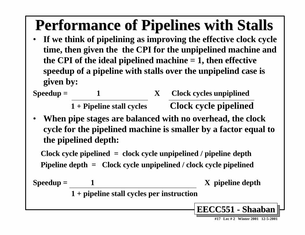
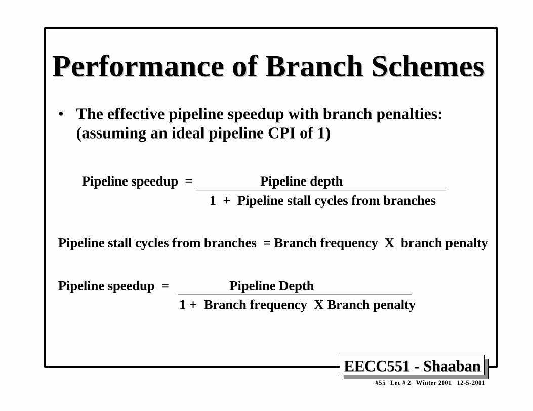
Performance of Pipelines with StallsPerformance of Pipelines with Stalls• If we think of pipelining as improving the effective clock cycle
time, then given the the CPI for the unpipelined machine andthe CPI of the ideal pipelined machine = 1, then effectivespeedup of a pipeline with stalls over the unpipelind case isgiven by:
Speedup = 1 X Clock cycles unpiplined
1 + Pipeline stall cycles Clock cycle pipelined• When pipe stages are balanced with no overhead, the clock
cycle for the pipelined machine is smaller by a factor equal tothe pipelined depth:
Clock cycle pipelined = clock cycle unpipelined / pipeline depth Pipeline depth = Clock cycle unpipelined / clock cycle pipelined
Speedup = 1 X pipeline depth 1 + pipeline stall cycles per instruction
EECC551 - ShaabanEECC551 - Shaaban#18 Lec # 2 Winter 2001 12-5-2001
Structural HazardsStructural Hazards• In pipelined machines overlapped instruction execution
requires pipelining of functional units and duplication ofresources to allow all possible combinations of instructionsin the pipeline.
• If a resource conflict arises due to a hardware resourcebeing required by more than one instruction in a singlecycle, and one or more such instructions cannot beaccommodated, then a structural hazard has occurred,for example:
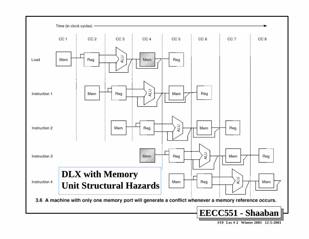
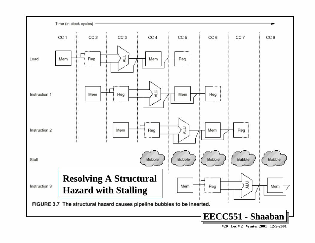
– when a machine has only one register file write port– or when a pipelined machine has a shared single-
memory pipeline for data and instructions.→ stall the pipeline for one cycle for register writes or
memory data access
EECC551 - ShaabanEECC551 - Shaaban#19 Lec # 2 Winter 2001 12-5-2001
DLX with MemoryDLX with MemoryUnit Structural HazardsUnit Structural Hazards
EECC551 - ShaabanEECC551 - Shaaban#20 Lec # 2 Winter 2001 12-5-2001
Resolving A StructuralResolving A StructuralHazard with StallingHazard with Stalling
EECC551 - ShaabanEECC551 - Shaaban#21 Lec # 2 Winter 2001 12-5-2001
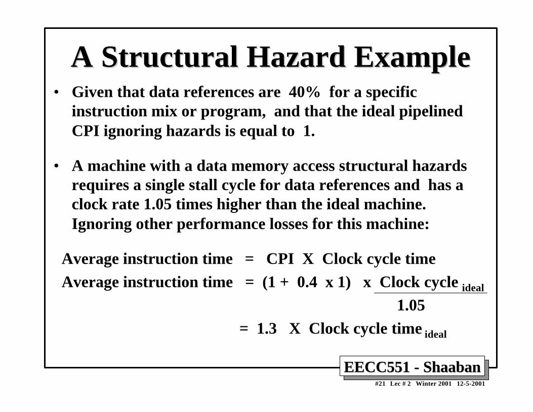
A Structural Hazard ExampleA Structural Hazard Example• Given that data references are 40% for a specific
instruction mix or program, and that the ideal pipelinedCPI ignoring hazards is equal to 1.
• A machine with a data memory access structural hazardsrequires a single stall cycle for data references and has aclock rate 1.05 times higher than the ideal machine.Ignoring other performance losses for this machine:
Average instruction time = CPI X Clock cycle time Average instruction time = (1 + 0.4 x 1) x Clock cycle ideal
1.05 = 1.3 X Clock cycle time ideal
EECC551 - ShaabanEECC551 - Shaaban#22 Lec # 2 Winter 2001 12-5-2001
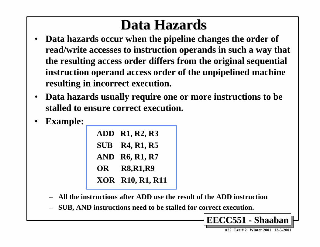
Data HazardsData Hazards• Data hazards occur when the pipeline changes the order of
read/write accesses to instruction operands in such a way thatthe resulting access order differs from the original sequentialinstruction operand access order of the unpipelined machineresulting in incorrect execution.
• Data hazards usually require one or more instructions to bestalled to ensure correct execution.
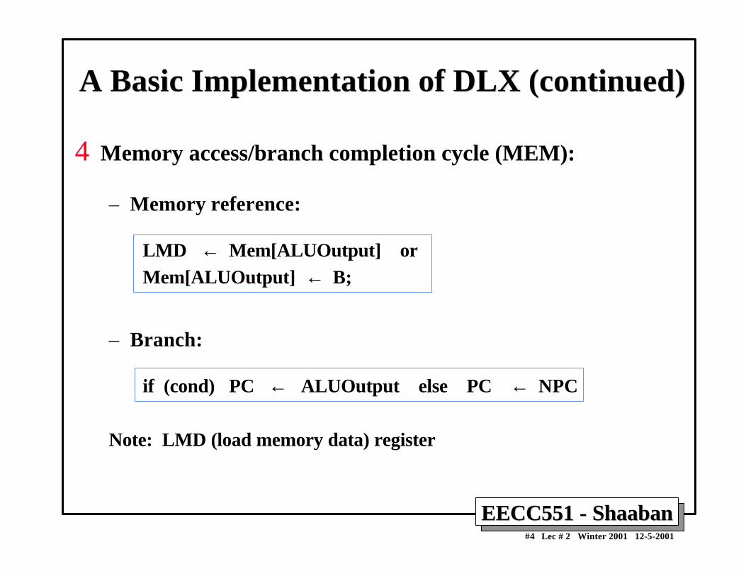
• Example: ADD R1, R2, R3 SUB R4, R1, R5 AND R6, R1, R7 OR R8,R1,R9 XOR R10, R1, R11
– All the instructions after ADD use the result of the ADD instruction
– SUB, AND instructions need to be stalled for correct execution.
EECC551 - ShaabanEECC551 - Shaaban#23 Lec # 2 Winter 2001 12-5-2001
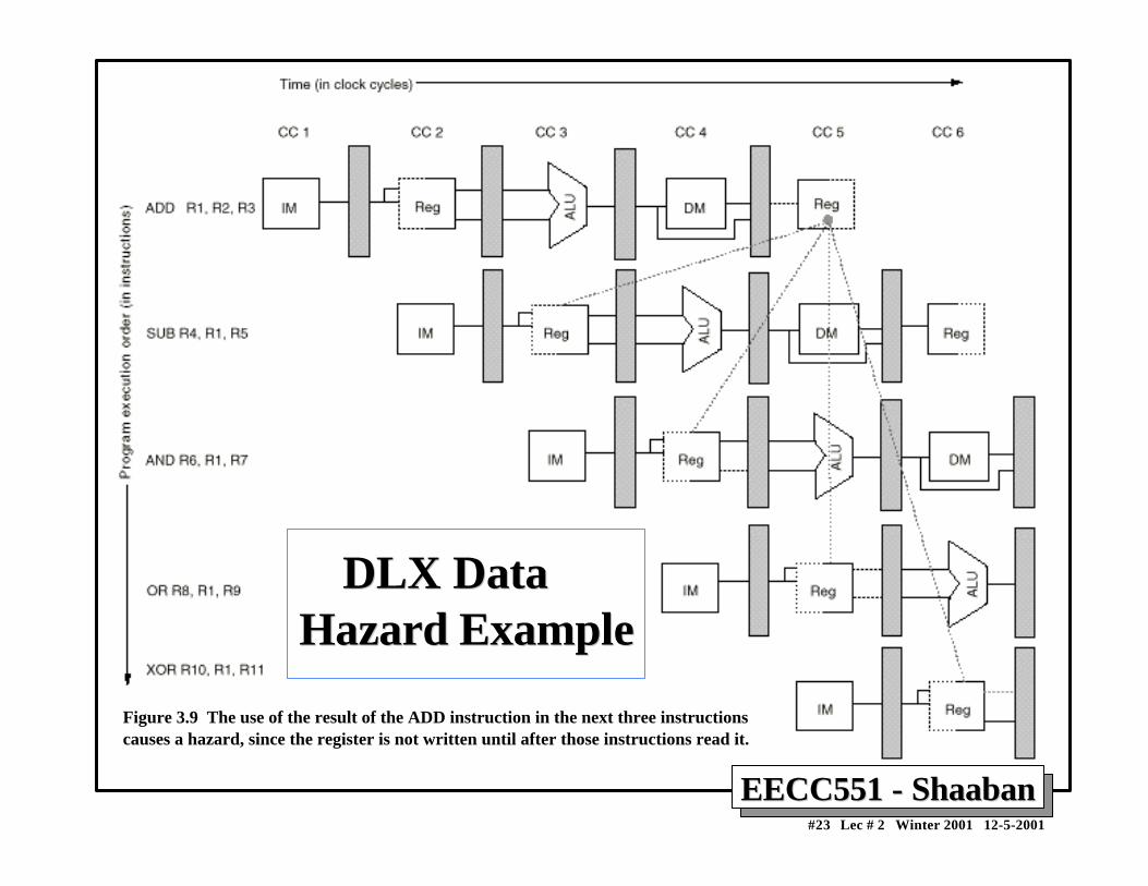
Figure 3.9 The use of the result of the ADD instruction in the next three instructionscauses a hazard, since the register is not written until after those instructions read it.
DLX Data DLX Data Hazard ExampleHazard Example
EECC551 - ShaabanEECC551 - Shaaban#24 Lec # 2 Winter 2001 12-5-2001
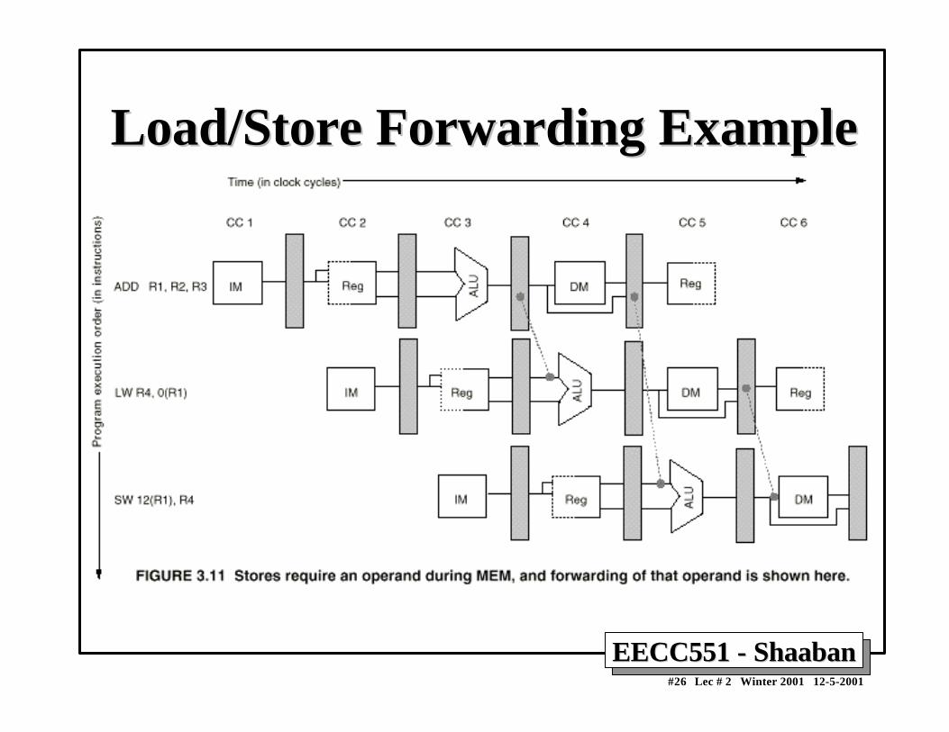
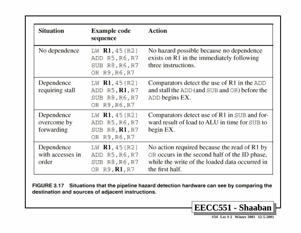
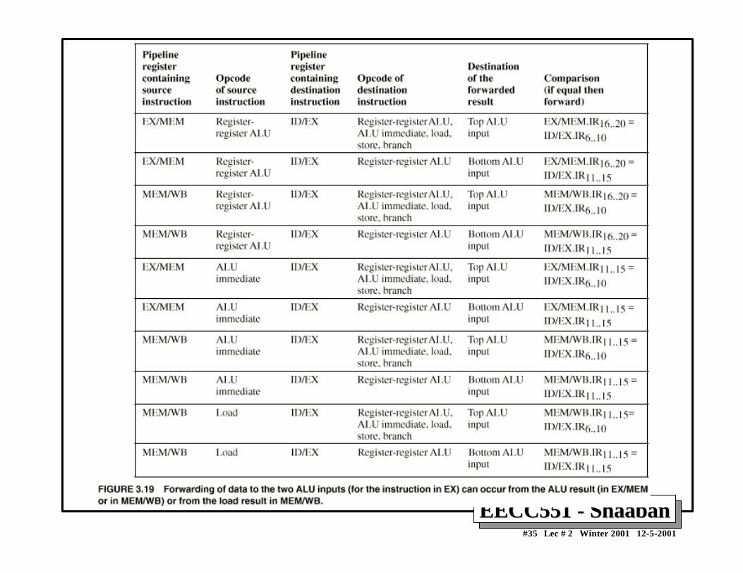
Minimizing Data hazard Stalls by ForwardingMinimizing Data hazard Stalls by Forwarding• Forwarding is a hardware-based technique (also called register
bypassing or short-circuiting) used to eliminate or minimizedata hazard stalls.
• Using forwarding hardware, the result of an instruction is copieddirectly from where it is produced (ALU, memory read portetc.), to where subsequent instructions need it (ALU inputregister, memory write port etc.)
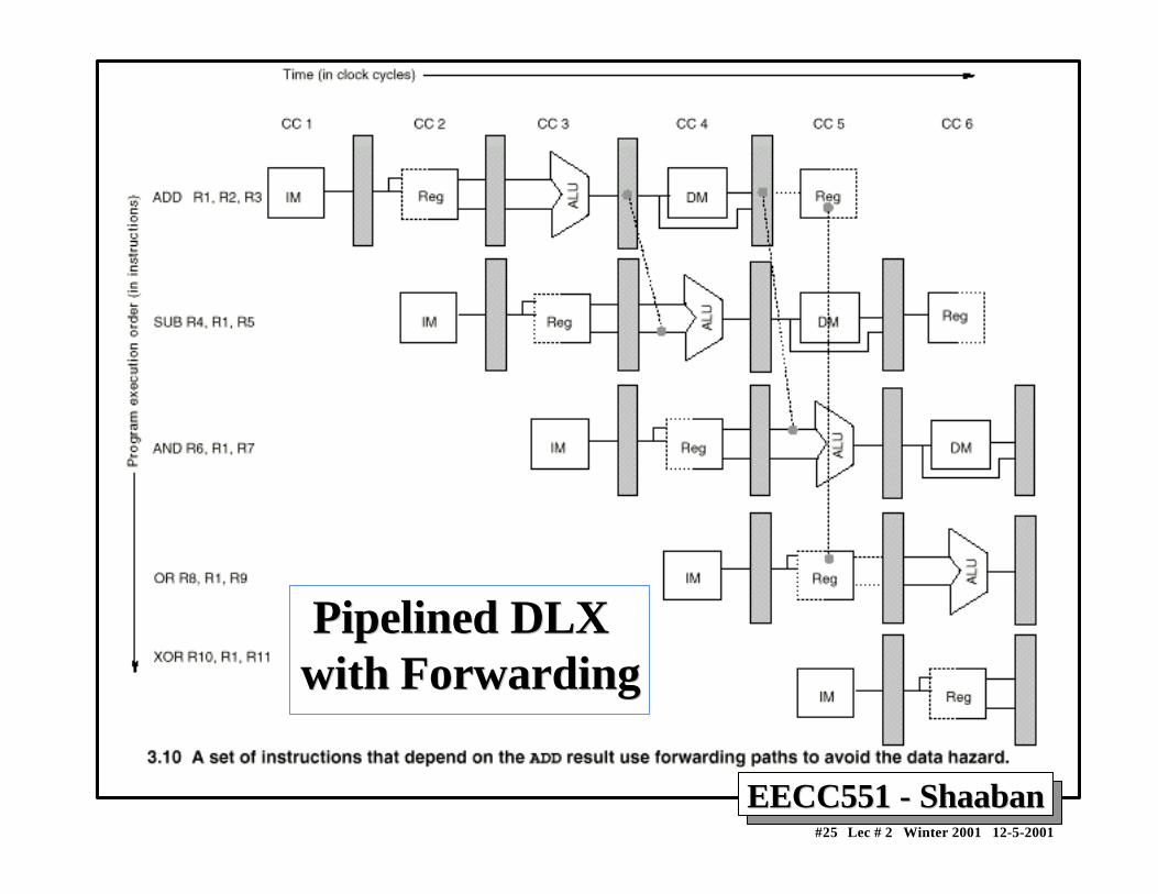
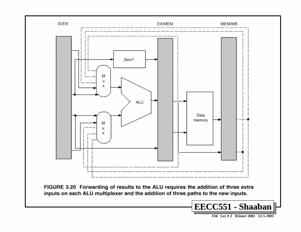
• For example, in the DLX pipeline with forwarding:– The ALU result from the EX/MEM register may be forwarded or fed
back to the ALU input latches as needed instead of the registeroperand value read in the ID stage.
– Similarly, the Data Memory Unit result from the MEM/WB registermay be fed back to the ALU input latches as needed .
– If the forwarding hardware detects that a previous ALU operation is towrite the register corresponding to a source for the current ALUoperation, control logic selects the forwarded result as the ALU inputrather than the value read from the register file.
EECC551 - ShaabanEECC551 - Shaaban#25 Lec # 2 Winter 2001 12-5-2001
Pipelined DLX Pipelined DLXwith Forwardingwith Forwarding
EECC551 - ShaabanEECC551 - Shaaban#26 Lec # 2 Winter 2001 12-5-2001
Load/Store Forwarding ExampleLoad/Store Forwarding Example
EECC551 - ShaabanEECC551 - Shaaban#27 Lec # 2 Winter 2001 12-5-2001
Data Hazard ClassificationData Hazard Classification Given two instructions I, J, with I occurring before J
in an instruction stream:
• RAW (read after write): A true data dependence
J tried to read a source before I writes to it, so J incorrectly gets the old value.
• WAW (write after write): A name dependence
J tries to write an operand before it is written by I The writes end up being performed in the wrong order.
• WAR (write after read): A name dependence
J tries to write to a destination before it is read by I, so I incorrectly gets the new value.
• RAR (read after read): Not a hazard.
EECC551 - ShaabanEECC551 - Shaaban#28 Lec # 2 Winter 2001 12-5-2001
Data Hazard ClassificationData Hazard ClassificationI (Write)
Shared Operand
J (Read)
Read after Write (RAW)
I (Read)
Shared Operand
J (Write)
Write after Read (WAR)
I (Write)
Shared Operand
J (Write)
Write after Write (WAW)
I (Read)
Shared Operand
J (Read)
Read after Read (RAR) not a hazard
EECC551 - ShaabanEECC551 - Shaaban#29 Lec # 2 Winter 2001 12-5-2001
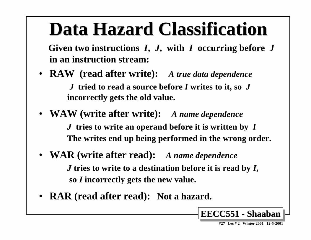
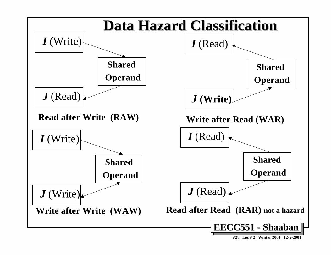
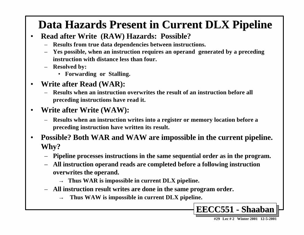
Data Hazards Present in Current DLX PipelineData Hazards Present in Current DLX Pipeline• Read after Write (RAW) Hazards: Possible?
– Results from true data dependencies between instructions.– Yes possible, when an instruction requires an operand generated by a preceding
instruction with distance less than four.– Resolved by:
• Forwarding or Stalling.
• Write after Read (WAR):– Results when an instruction overwrites the result of an instruction before all
preceding instructions have read it.
• Write after Write (WAW):– Results when an instruction writes into a register or memory location before a
preceding instruction have written its result.
• Possible? Both WAR and WAW are impossible in the current pipeline.Why?
– Pipeline processes instructions in the same sequential order as in the program.– All instruction operand reads are completed before a following instruction
overwrites the operand.→ Thus WAR is impossible in current DLX pipeline.
– All instruction result writes are done in the same program order.→ Thus WAW is impossible in current DLX pipeline.
EECC551 - ShaabanEECC551 - Shaaban#30 Lec # 2 Winter 2001 12-5-2001
Data Hazards Requiring Stall CyclesData Hazards Requiring Stall Cycles• In some code sequence cases, potential data hazards
cannot be handled by bypassing. For example:
LW R1, 0 (R2) SUB R4, R1, R5 AND R6, R1, R7 OR R8, R1, R9
• The LW (load word) instruction has the data in clockcycle 4 (MEM cycle).
• The SUB instruction needs the data of R1 in thebeginning of that cycle.
• Hazard prevented by hardware pipeline interlockcausing a stall cycle.
EECC551 - ShaabanEECC551 - Shaaban#32 Lec # 2 Winter 2001 12-5-2001
Hardware Pipeline InterlocksHardware Pipeline Interlocks• A hardware pipeline interlock detects a data hazard and
stalls the pipeline until the hazard is cleared.
• The CPI for the stalled instruction increases by thelength of the stall.
• For the Previous example, (no stall cycle):
LW R1, 0(R1) IF ID EX MEM WBSUB R4,R1,R5 IF ID EX MEM WBAND R6,R1,R7 IF ID EX MEM WBOR R8, R1, R9 IF ID EX MEM WB
With Stall Cycle:
LW R1, 0(R1) IF ID EX MEM WBSUB R4,R1,R5 IF ID STALL EX MEM WBAND R6,R1,R7 IF STALL ID EX MEM WBOR R8, R1, R9 STALL IF ID EX MEM WB
EECC551 - ShaabanEECC551 - Shaaban#37 Lec # 2 Winter 2001 12-5-2001
Compiler Instruction SchedulingCompiler Instruction Schedulingfor Data Hazard Stall Reductionfor Data Hazard Stall Reduction
• Many types of stalls resulting from data hazards are veryfrequent. For example:
A = B + C
produces a stall when loading the second data value (B).
• Rather than allow the pipeline to stall, the compiler couldsometimes schedule the pipeline to avoid stalls.
• Compiler pipeline or instruction scheduling involvesrearranging the code sequence (instruction reordering)to eliminate the hazard.
EECC551 - ShaabanEECC551 - Shaaban#38 Lec # 2 Winter 2001 12-5-2001
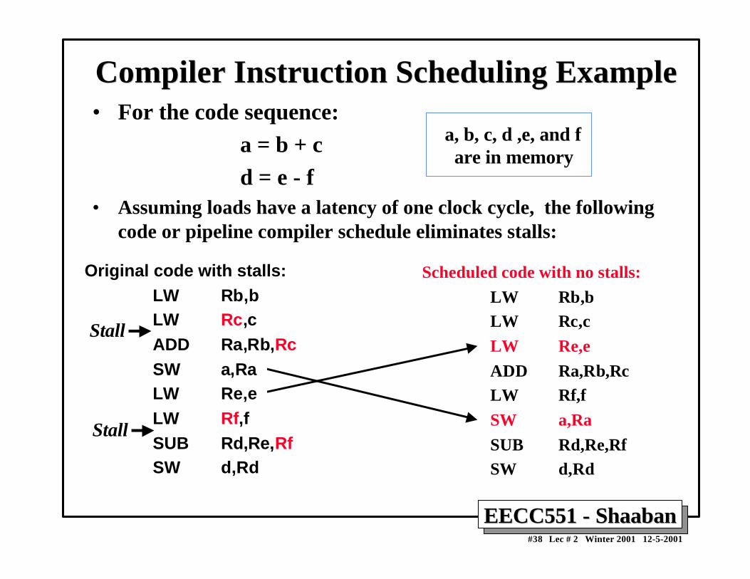
Compiler Instruction Scheduling ExampleCompiler Instruction Scheduling Example• For the code sequence: a = b + c d = e - f• Assuming loads have a latency of one clock cycle, the following
code or pipeline compiler schedule eliminates stalls:
a, b, c, d ,e, and f are in memory
Scheduled code with no stalls:
LW Rb,bLW Rc,c
LW Re,e
ADD Ra,Rb,RcLW Rf,f
SW a,Ra
SUB Rd,Re,RfSW d,Rd
Original code with stalls:LW Rb,bLW Rc,cADD Ra,Rb,RcSW a,Ra LW Re,e LW Rf,fSUB Rd,Re,RfSW d,Rd
Stall
Stall
EECC551 - ShaabanEECC551 - Shaaban#39 Lec # 2 Winter 2001 12-5-2001
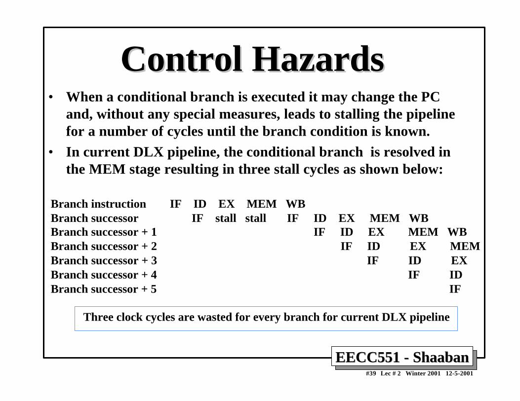
Control HazardsControl Hazards• When a conditional branch is executed it may change the PC
and, without any special measures, leads to stalling the pipelinefor a number of cycles until the branch condition is known.
• In current DLX pipeline, the conditional branch is resolved inthe MEM stage resulting in three stall cycles as shown below:
Branch instruction IF ID EX MEM WBBranch successor IF stall stall IF ID EX MEM WBBranch successor + 1 IF ID EX MEM WB Branch successor + 2 IF ID EX MEMBranch successor + 3 IF ID EXBranch successor + 4 IF IDBranch successor + 5 IF
Three clock cycles are wasted for every branch for current DLX pipeline
EECC551 - ShaabanEECC551 - Shaaban#40 Lec # 2 Winter 2001 12-5-2001
Reducing Branch Stall CyclesReducing Branch Stall CyclesPipeline hardware measures to reduce branch stall cycles:
1- Find out whether a branch is taken earlier in the pipeline. 2- Compute the taken PC earlier in the pipeline.
In DLX:
– In DLX branch instructions BEQZ, BNEZ, test a registerfor equality to zero.
– This can be completed in the ID cycle by moving the zerotest into that cycle.
– Both PCs (taken and not taken) must be computed early.
– Requires an additional adder because the current ALU isnot useable until EX cycle.
– This results in just a single cycle stall on branches.
EECC551 - ShaabanEECC551 - Shaaban#41 Lec # 2 Winter 2001 12-5-2001
Modified DLX Pipeline:Modified DLX Pipeline: Conditional Branches Conditional Branches Completed in ID Stage Completed in ID Stage
EECC551 - ShaabanEECC551 - Shaaban#42 Lec # 2 Winter 2001 12-5-2001
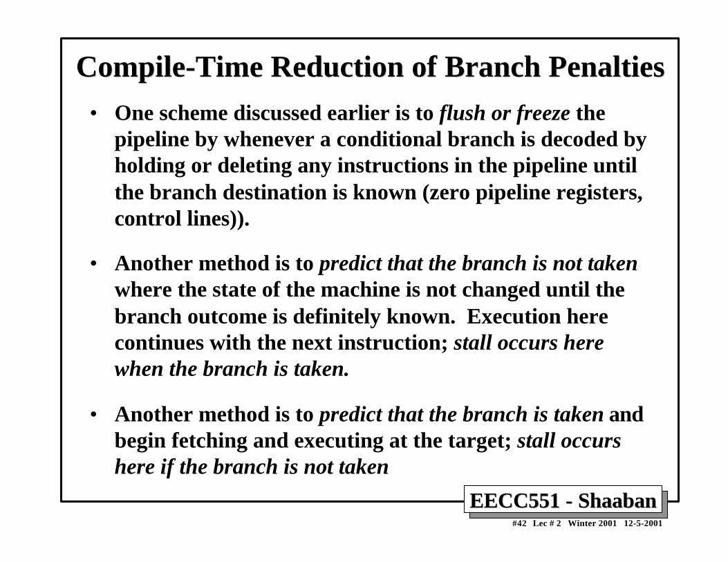
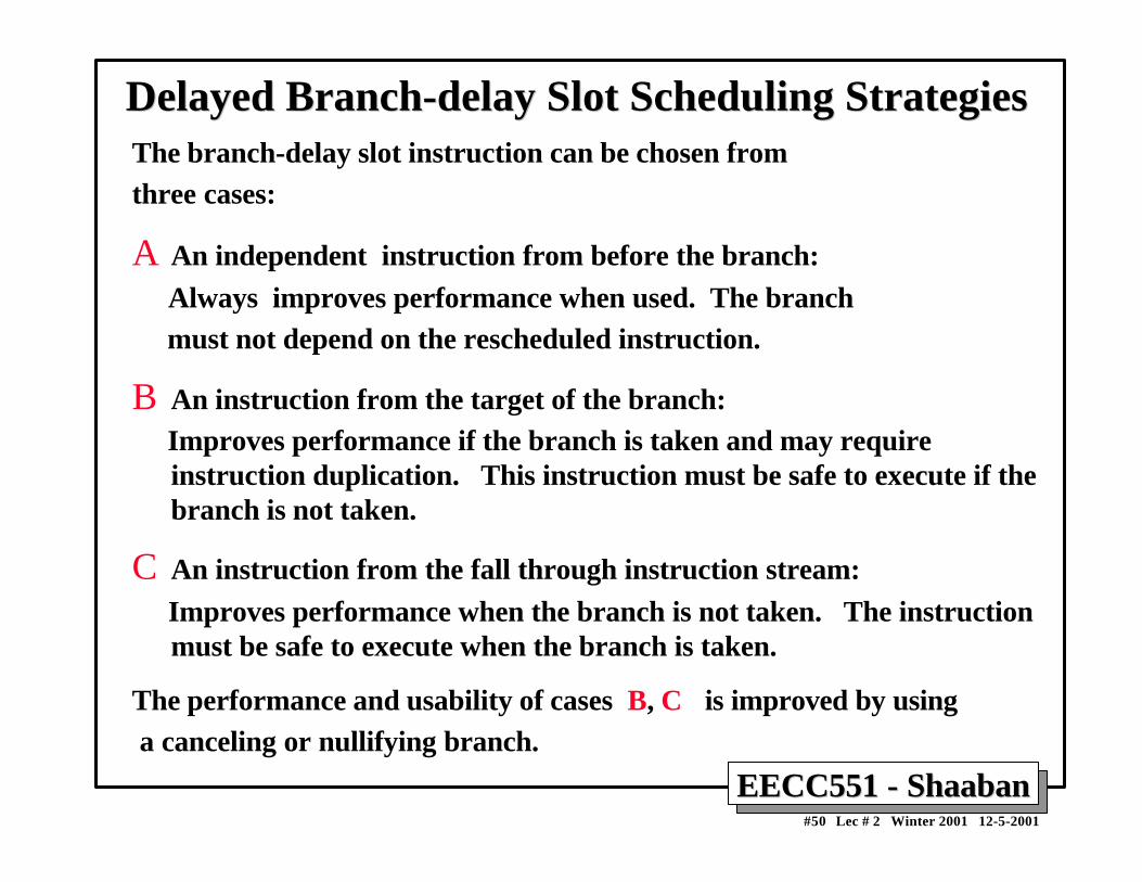
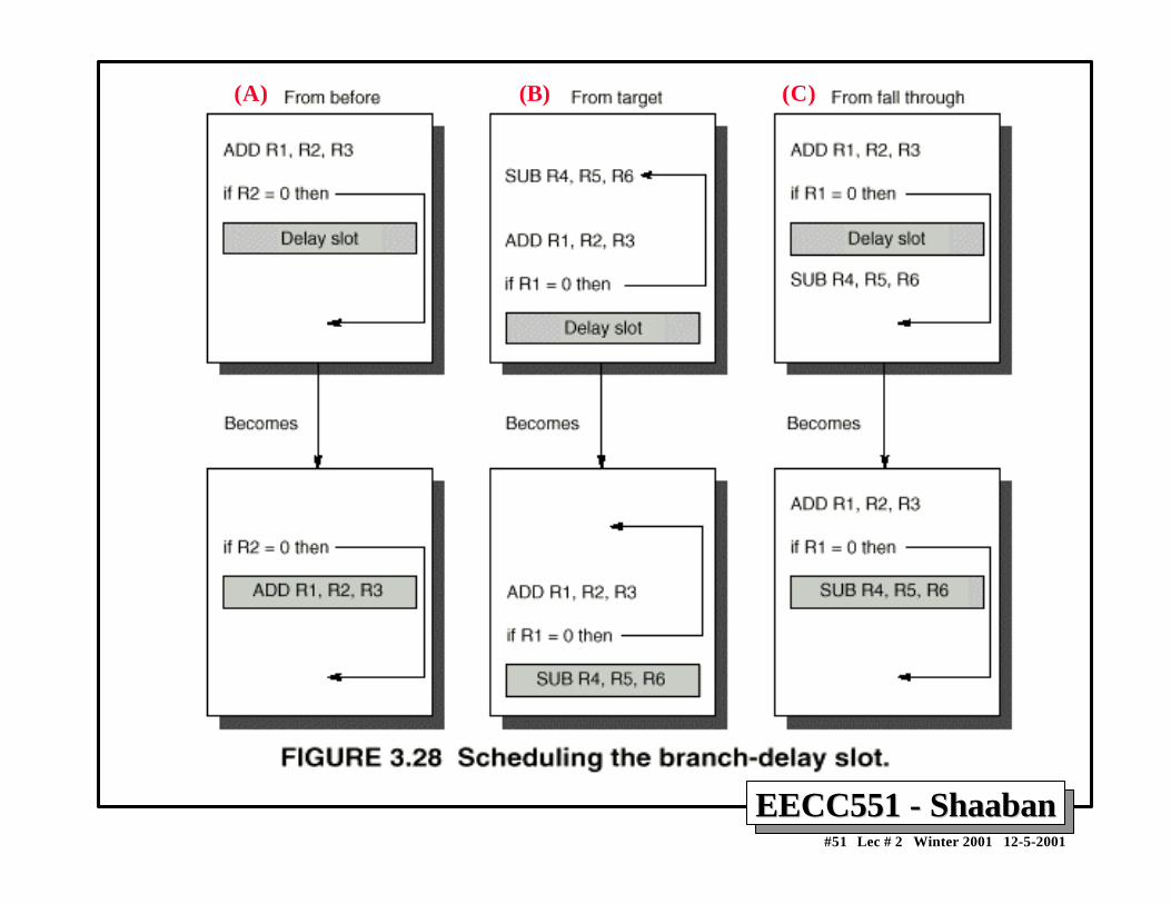
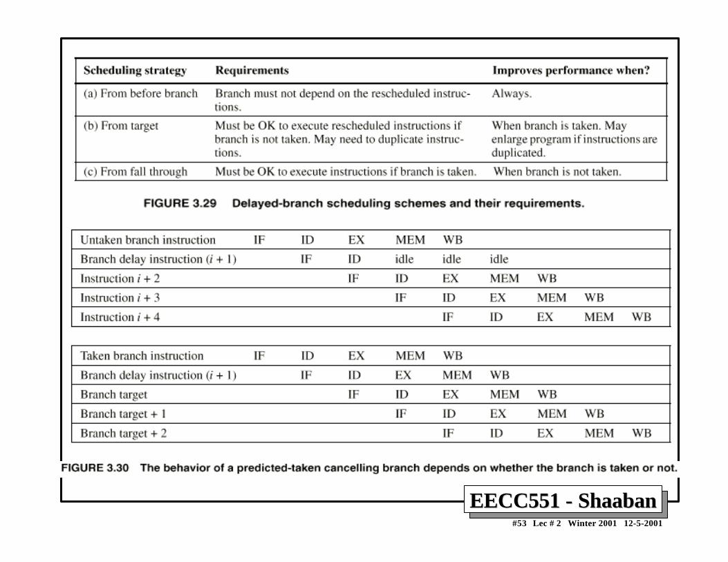
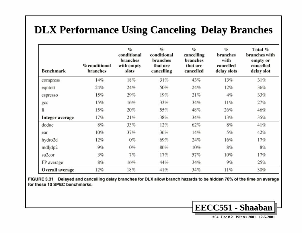
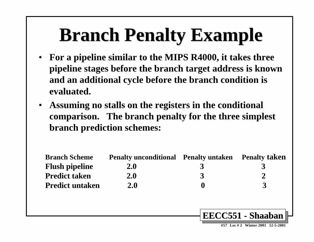
Compile-Time Reduction of Branch PenaltiesCompile-Time Reduction of Branch Penalties• One scheme discussed earlier is to flush or freeze the
pipeline by whenever a conditional branch is decoded byholding or deleting any instructions in the pipeline untilthe branch destination is known (zero pipeline registers,control lines)).
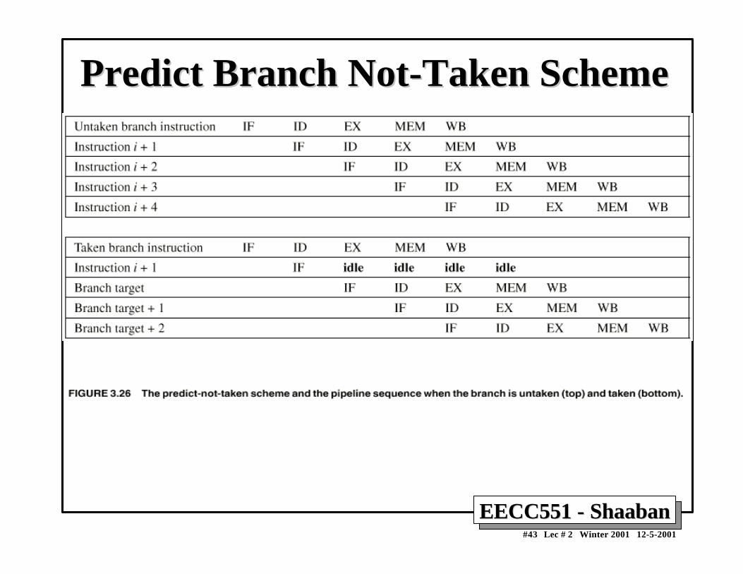
• Another method is to predict that the branch is not takenwhere the state of the machine is not changed until thebranch outcome is definitely known. Execution herecontinues with the next instruction; stall occurs herewhen the branch is taken.
• Another method is to predict that the branch is taken andbegin fetching and executing at the target; stall occurshere if the branch is not taken
EECC551 - ShaabanEECC551 - Shaaban#43 Lec # 2 Winter 2001 12-5-2001
Predict Branch Not-Taken SchemePredict Branch Not-Taken Scheme
EECC551 - ShaabanEECC551 - Shaaban#44 Lec # 2 Winter 2001 12-5-2001
Static Compiler Branch PredictionStatic Compiler Branch PredictionTwo basic methods exist to statically predict branchesat compile time:
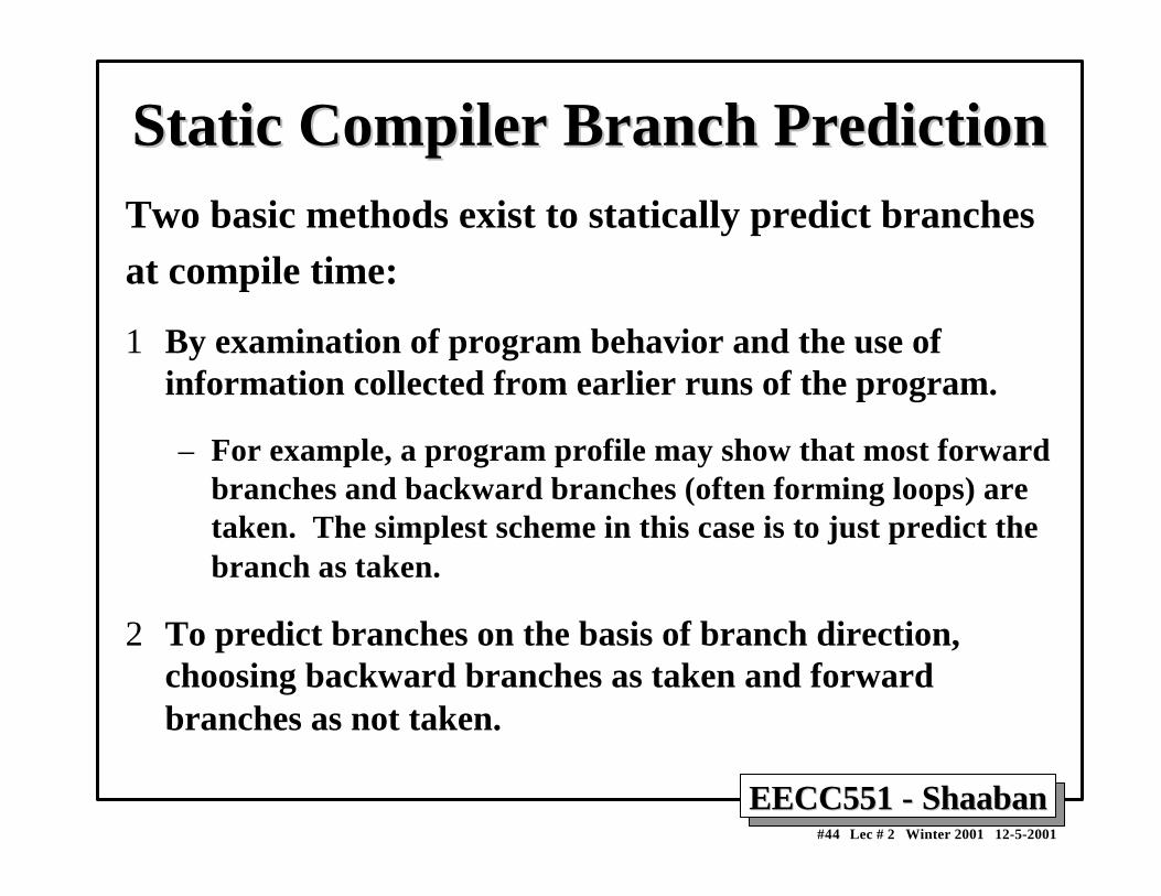
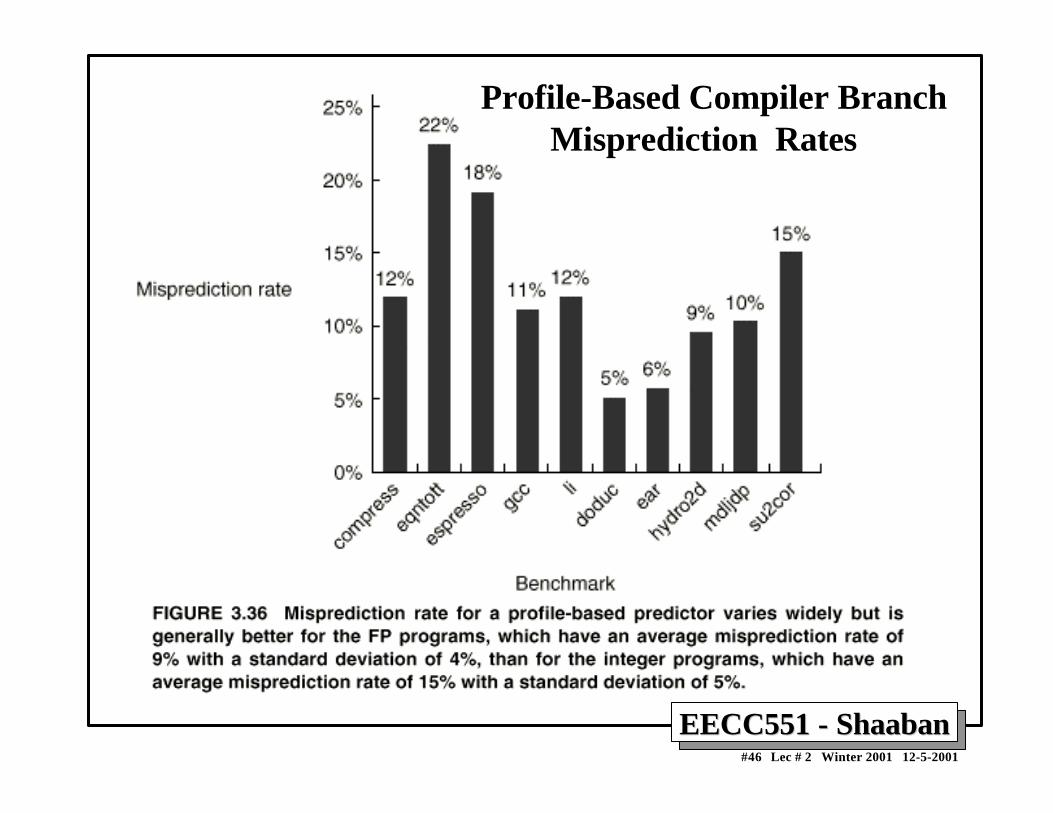
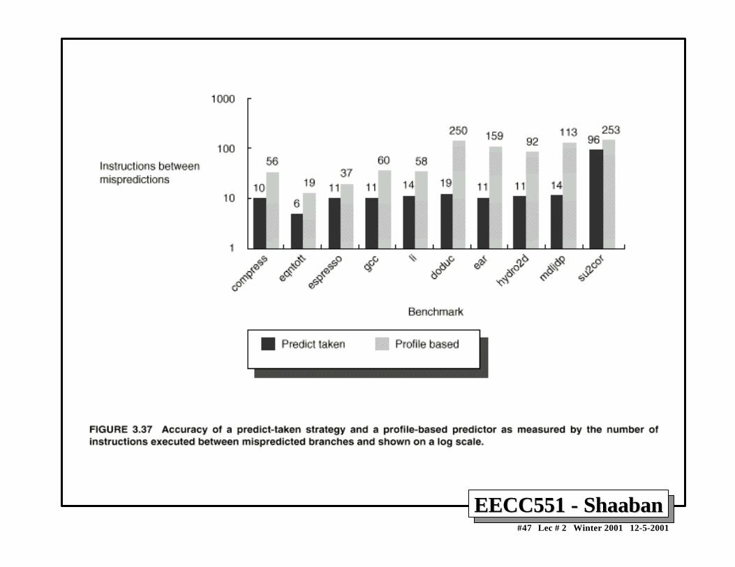
1 By examination of program behavior and the use ofinformation collected from earlier runs of the program.
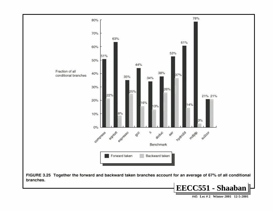
– For example, a program profile may show that most forwardbranches and backward branches (often forming loops) aretaken. The simplest scheme in this case is to just predict thebranch as taken.
2 To predict branches on the basis of branch direction,choosing backward branches as taken and forwardbranches as not taken.
EECC551 - ShaabanEECC551 - Shaaban#46 Lec # 2 Winter 2001 12-5-2001
Profile-Based Compiler Branch Misprediction Rates
EECC551 - ShaabanEECC551 - Shaaban#48 Lec # 2 Winter 2001 12-5-2001
Reduction of Branch Penalties:Reduction of Branch Penalties:Delayed BranchDelayed Branch
• When delayed branch is used, the branch is delayed by n cycles,following this execution pattern:
conditional branch instruction sequential successor1
sequential successor2
…….. sequential successorn
branch target if taken
• The sequential successor instruction are said to be in the branchdelay slots. These instructions are executed whether or not thebranch is taken.
• In Practice, all machines that utilize delayed branching have a single instruction delay slot.
• The job of the compiler is to make the successor instructions valid and useful instructions.
EECC551 - ShaabanEECC551 - Shaaban#49 Lec # 2 Winter 2001 12-5-2001
Delayed Branch ExampleDelayed Branch Example
EECC551 - ShaabanEECC551 - Shaaban#50 Lec # 2 Winter 2001 12-5-2001
Delayed Branch-delay Slot Scheduling StrategiesDelayed Branch-delay Slot Scheduling StrategiesThe branch-delay slot instruction can be chosen fromthree cases:
A An independent instruction from before the branch: Always improves performance when used. The branch must not depend on the rescheduled instruction.
B An instruction from the target of the branch: Improves performance if the branch is taken and may require
instruction duplication. This instruction must be safe to execute if thebranch is not taken.
C An instruction from the fall through instruction stream: Improves performance when the branch is not taken. The instruction
must be safe to execute when the branch is taken.
The performance and usability of cases B, C is improved by using a canceling or nullifying branch.
EECC551 - ShaabanEECC551 - Shaaban#52 Lec # 2 Winter 2001 12-5-2001
Branch-delay Slot: Canceling BranchesBranch-delay Slot: Canceling Branches• In a canceling branch, a static compiler branch direction
prediction is included with the branch-delay slotinstruction.
• When the branch goes as predicted, the instruction in thebranch delay slot is executed normally.
• When the branch does not go as predicted the instructionis turned into a no-op.
• Canceling branches eliminate the conditions oninstruction selection in delay instruction strategies B, C
• The effectiveness of this method depends on whether wepredict the branch correctly.
EECC551 - ShaabanEECC551 - Shaaban#54 Lec # 2 Winter 2001 12-5-2001
DLX Performance Using Canceling Delay BranchesDLX Performance Using Canceling Delay Branches
EECC551 - ShaabanEECC551 - Shaaban#55 Lec # 2 Winter 2001 12-5-2001
Performance of Branch SchemesPerformance of Branch Schemes• The effective pipeline speedup with branch penalties:
(assuming an ideal pipeline CPI of 1)
Pipeline speedup = Pipeline depth 1 + Pipeline stall cycles from branches
Pipeline stall cycles from branches = Branch frequency X branch penalty
Pipeline speedup = Pipeline Depth 1 + Branch frequency X Branch penalty
EECC551 - ShaabanEECC551 - Shaaban#56 Lec # 2 Winter 2001 12-5-2001
Pipeline Performance ExamplePipeline Performance Example• Assume the following DLX instruction mix:
• What is the resulting CPI for the pipelined DLX withforwarding and branch address calculation in ID stagewhen using a branch not-taken scheme?
• CPI = Ideal CPI + Pipeline stall clock cycles per instruction
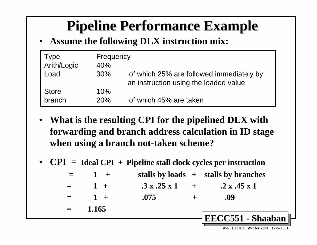
= 1 + stalls by loads + stalls by branches = 1 + .3 x .25 x 1 + .2 x .45 x 1 = 1 + .075 + .09 = 1.165
Type FrequencyArith/Logic 40%Load 30% of which 25% are followed immediately by an instruction using the loaded valueStore 10%branch 20% of which 45% are taken
EECC551 - ShaabanEECC551 - Shaaban#57 Lec # 2 Winter 2001 12-5-2001
Branch Penalty ExampleBranch Penalty Example• For a pipeline similar to the MIPS R4000, it takes three
pipeline stages before the branch target address is knownand an additional cycle before the branch condition isevaluated.
• Assuming no stalls on the registers in the conditionalcomparison. The branch penalty for the three simplestbranch prediction schemes:
Branch Scheme Penalty unconditional Penalty untaken Penalty takenFlush pipeline 2.0 3 3Predict taken 2.0 3 2Predict untaken 2.0 0 3
EECC551 - ShaabanEECC551 - Shaaban#58 Lec # 2 Winter 2001 12-5-2001
Pipelining and Handling of ExceptionsPipelining and Handling of Exceptions• Exceptions are events that usually occur in normal program execution
where the normal execution order of the instructions is changed (oftencalled: interrupts, faults).
• Types of exceptions include:
• I/O device request• Invoking an operating system service• Tracing instruction execution• Breakpoint (programmer-requested interrupt).• Integer overflow or underflow• FP anomaly• Page fault (not in main memory)• Misaligned memory access• Memory protection violation• Undefined instruction• Hardware malfunctions
EECC551 - ShaabanEECC551 - Shaaban#59 Lec # 2 Winter 2001 12-5-2001
Exception event IBM 360 VAX Motorola 680x0 Intel 80x86
I/O device request Input/output interruption
Device interrupt Exception (Level 0...7 autovector)
Vectored interrupt
Tracing instruction execution
Not applicable Exception (trace fault)
Exception (trace) Interrupt (single- step trap)
Invoking the operat- ing system service from a user program
Supervisor call interruption
Exception (change mode supervisor trap)
Exception (unimplemented instruction)--- on Macintosh
Interrupt (INT instruction)
Page fault (not in main memory)
Not applicable (only in 370)
Exception (transla- tion not valid fault)
Exception (memory- management unit errors)
Interrupt (page fault)
Misaligned memory accesses
Program interrup- tion (specification exception)
Not applicable Exception (address error)
Not applicable
Using undefined instructions
Program interrup- tion (operation exception)
Exception (opcode privileged/ reserved fault)
Exception (illegal instruction or break- point/unimplemented instruction)
Interrupt (invalid opcode)
Hardware malfunctions
Machine-check interruption
Exception (machine-check abort)
Exception (bus error)
Not applicable
Breakpoint Not applicable Exception (break- point fault)
Exception (illegal instruction or break- point)
Interrupt (break- point trap)
Integer arithmetic overflow or under- flow; FP trap
Program interrup- tion (overflow or underflow exception)
Exception (integer overflow trap or floating underflow fault)
Exception (floating-point coprocessor errors)
Interrupt (overflow trap or math unit exception)
Memory protection violations
Program interrup- tion (protection exception)
Exception (access control violation fault)
Exception (bus error)
Interrupt (protection exception)
Power failure Machine-check interruption
Urgent interrupt Not applicable Nonmaskable interrupt
The names of common exceptions vary across four different architectures.
EECC551 - ShaabanEECC551 - Shaaban#60 Lec # 2 Winter 2001 12-5-2001
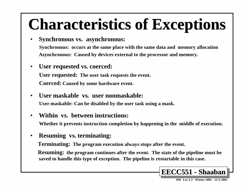
Characteristics of ExceptionsCharacteristics of Exceptions• Synchronous vs. asynchronous: Synchronous: occurs at the same place with the same data and memory allocation
Asynchronous: Caused by devices external to the processor and memory.
• User requested vs. coerced: User requested: The user task requests the event.
Coerced: Caused by some hardware event.
• User maskable vs. user nonmaskable: User maskable: Can be disabled by the user task using a mask.
• Within vs. between instructions: Whether it prevents instruction completion by happening in the middle of execution.
• Resuming vs. terminating: Terminating: The program execution always stops after the event.
Resuming: the program continues after the event. The state of the pipeline must besaved to handle this type of exception. The pipeline is restartable in this case.
EECC551 - ShaabanEECC551 - Shaaban#61 Lec # 2 Winter 2001 12-5-2001
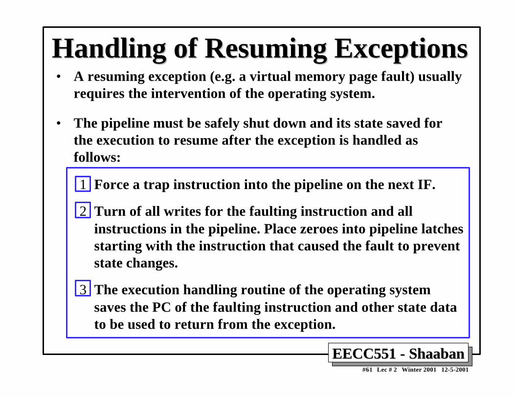
Handling of Resuming ExceptionsHandling of Resuming Exceptions• A resuming exception (e.g. a virtual memory page fault) usually
requires the intervention of the operating system.
• The pipeline must be safely shut down and its state saved forthe execution to resume after the exception is handled asfollows:
1 Force a trap instruction into the pipeline on the next IF.
2 Turn of all writes for the faulting instruction and allinstructions in the pipeline. Place zeroes into pipeline latchesstarting with the instruction that caused the fault to preventstate changes.
3 The execution handling routine of the operating systemsaves the PC of the faulting instruction and other state datato be used to return from the exception.
EECC551 - ShaabanEECC551 - Shaaban#62 Lec # 2 Winter 2001 12-5-2001
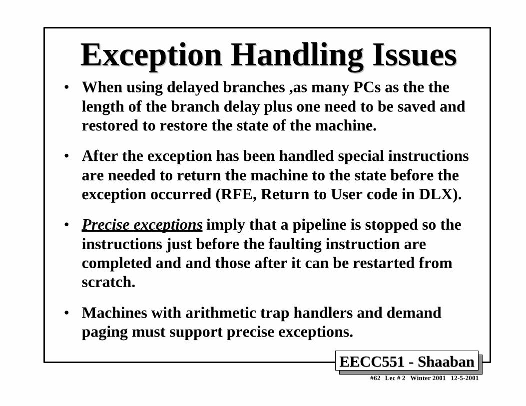
Exception Handling IssuesException Handling Issues• When using delayed branches ,as many PCs as the the
length of the branch delay plus one need to be saved andrestored to restore the state of the machine.
• After the exception has been handled special instructionsare needed to return the machine to the state before theexception occurred (RFE, Return to User code in DLX).
• Precise exceptions imply that a pipeline is stopped so theinstructions just before the faulting instruction arecompleted and and those after it can be restarted fromscratch.
• Machines with arithmetic trap handlers and demandpaging must support precise exceptions.
EECC551 - ShaabanEECC551 - Shaaban#63 Lec # 2 Winter 2001 12-5-2001
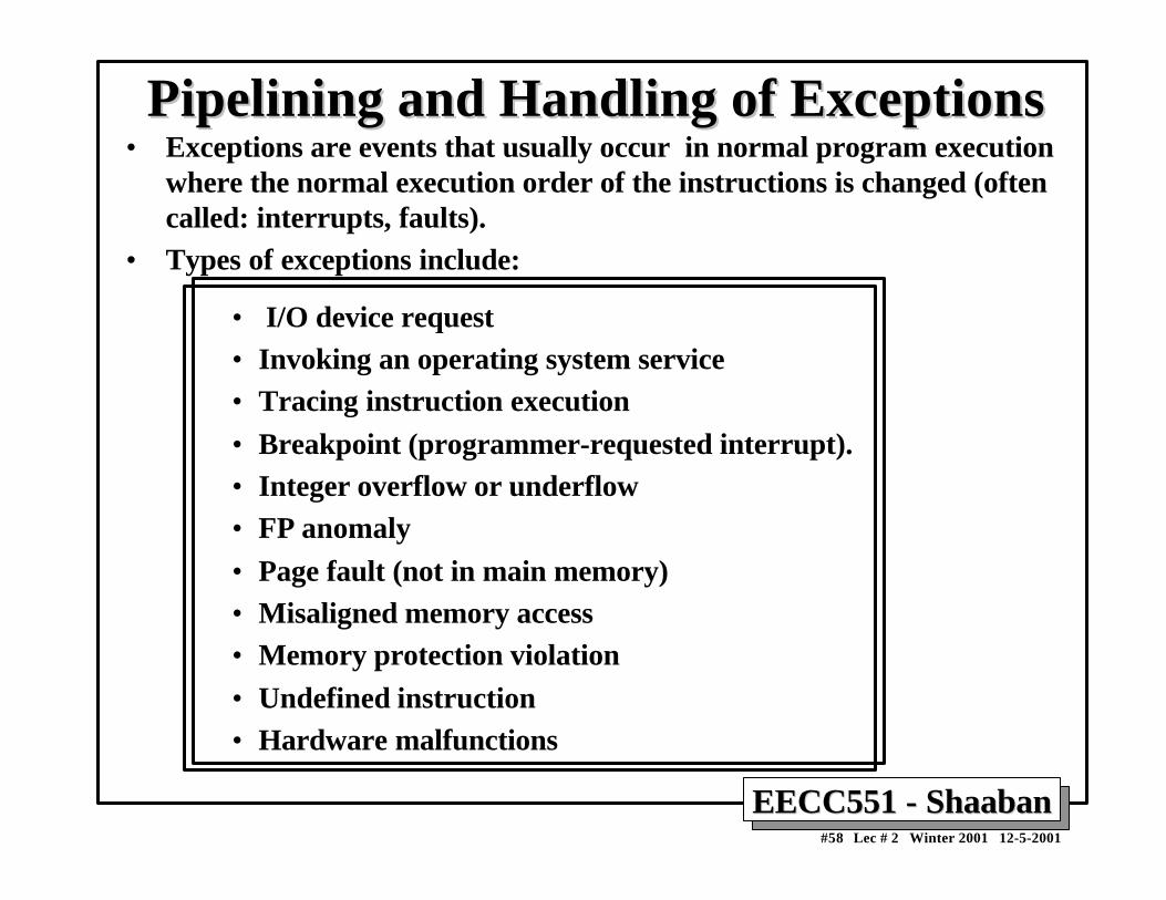
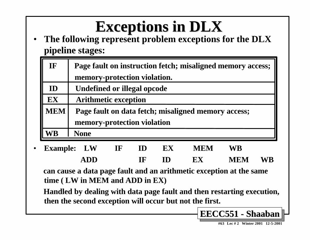
Exceptions in DLXExceptions in DLX• The following represent problem exceptions for the DLX
pipeline stages:
IF Page fault on instruction fetch; misaligned memory access; memory-protection violation. ID Undefined or illegal opcode EX Arithmetic exception MEM Page fault on data fetch; misaligned memory access; memory-protection violation WB None
• Example: LW IF ID EX MEM WB ADD IF ID EX MEM WB can cause a data page fault and an arithmetic exception at the same
time ( LW in MEM and ADD in EX) Handled by dealing with data page fault and then restarting execution,
then the second exception will occur but not the first.
EECC551 - ShaabanEECC551 - Shaaban#64 Lec # 2 Winter 2001 12-5-2001
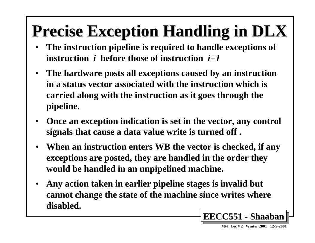
Precise Exception Handling in DLXPrecise Exception Handling in DLX• The instruction pipeline is required to handle exceptions of
instruction i before those of instruction i+1
• The hardware posts all exceptions caused by an instructionin a status vector associated with the instruction which iscarried along with the instruction as it goes through thepipeline.
• Once an exception indication is set in the vector, any controlsignals that cause a data value write is turned off .
• When an instruction enters WB the vector is checked, if anyexceptions are posted, they are handled in the order theywould be handled in an unpipelined machine.
• Any action taken in earlier pipeline stages is invalid butcannot change the state of the machine since writes wheredisabled.