Page 1
www.ffg-dmc.com
* Specifications in this catalog are subject to change without prior notice.
* Please contact us or visit our site for more product information.
FFG DMC CO.,LTD.631-821,86,Sandan 2-gil, Jinbuk-myeon, Masanhappo-gu, Changwon-si, Gyeongsangnam-do, KoreaPhone : +82-(0)55-340-8200Fax : +82-(0)55-340-8394E-mail : [email protected]
ⓀFFG DMC 2016.08.29
SINCE 1944
DM V/VC seriesVertical Machining Center (En)
DM V seriesDM 42V / DM 42VL / DM 52VL / DM 65V / DM 65V(#50) / FM 50V
DM VC series (Moving Column Type)DM 43VC / DM 43VCD
Page 2
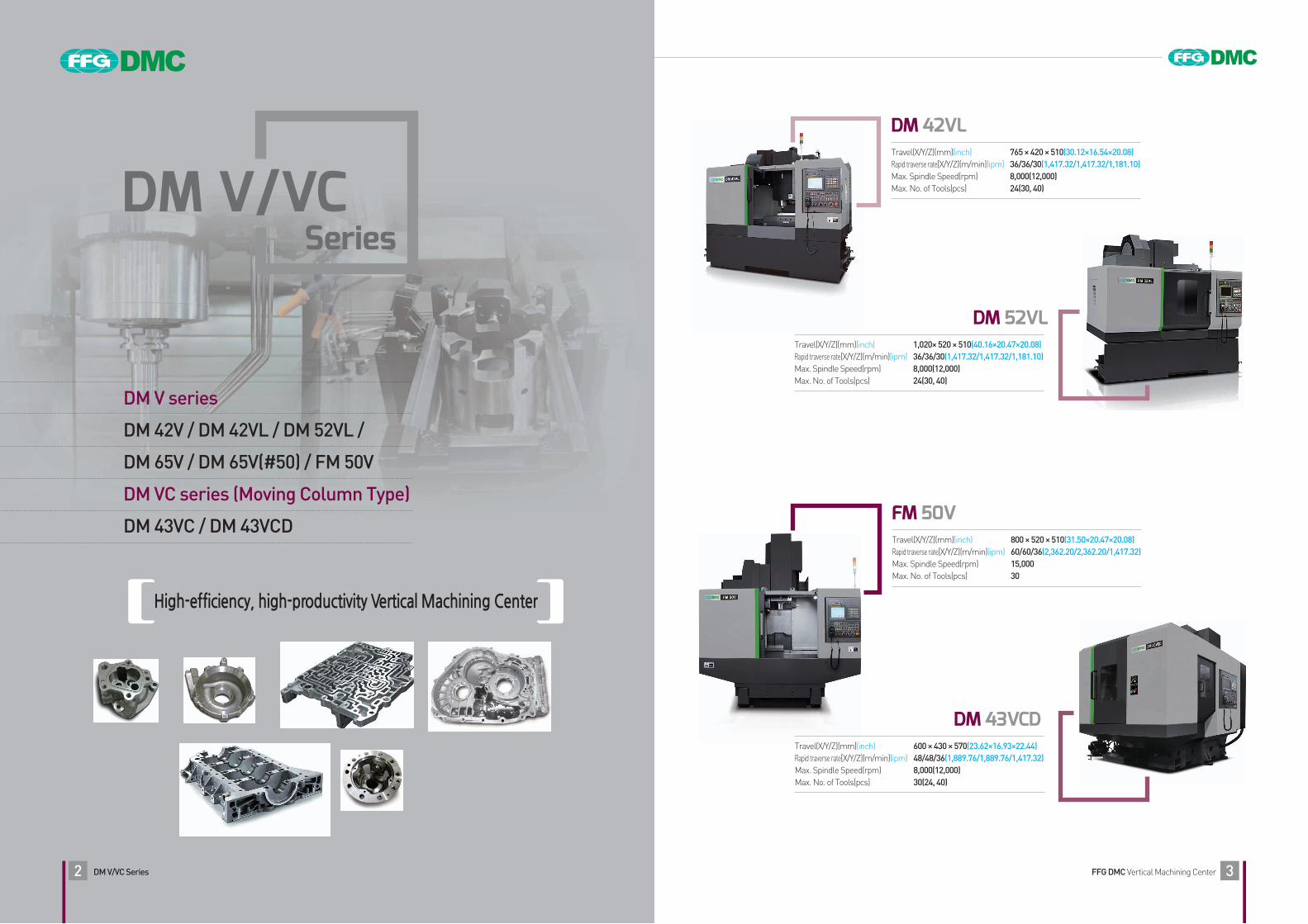
High-efficiency, high-productivity Vertical Machining Center
DM V/VCSeries
DM V series
DM 42V / DM 42VL / DM 52VL /
DM 65V / DM 65V(#50) / FM 50V
DM VC series (Moving Column Type)
DM 43VC / DM 43VCD
FFG DMC Vertical Machining CenterDM V/VC Series2 3
DM 42VLTravel(X/Y/Z)(mm)(inch) 765 × 420 × 510(30.12×16.54×20.08)Rapid traverse rate[X/Y/Z)(m/min)(ipm) 36/36/30(1,417.32/1,417.32/1,181.10)Max. Spindle Speed(rpm) 8,000(12,000)Max. No. of Tools(pcs) 24(30, 40)
Travel(X/Y/Z)(mm)(inch) 1,020× 520 × 510(40.16×20.47×20.08)Rapid traverse rate[X/Y/Z)(m/min)(ipm) 36/36/30(1,417.32/1,417.32/1,181.10)Max. Spindle Speed(rpm) 8,000(12,000)Max. No. of Tools(pcs) 24(30, 40)
FM 50VTravel(X/Y/Z)(mm)(inch) 800 × 520 × 510(31.50×20.47×20.08)Rapid traverse rate[X/Y/Z)(m/min)(ipm) 60/60/36(2,362.20/2,362.20/1,417.32)Max. Spindle Speed(rpm) 15,000Max. No. of Tools(pcs) 30
DM 43VCDTravel(X/Y/Z)(mm)(inch) 600 × 430 × 570(23.62×16.93×22.44)Rapid traverse rate[X/Y/Z)(m/min)(ipm) 48/48/36(1,889.76/1,889.76/1,417.32)Max. Spindle Speed(rpm) 8,000(12,000)Max. No. of Tools(pcs) 30(24, 40)
DM 52VL
Page 3
DM V/VC series
FFG DMC Vertical Machining CenterDM V/VC Series4 5
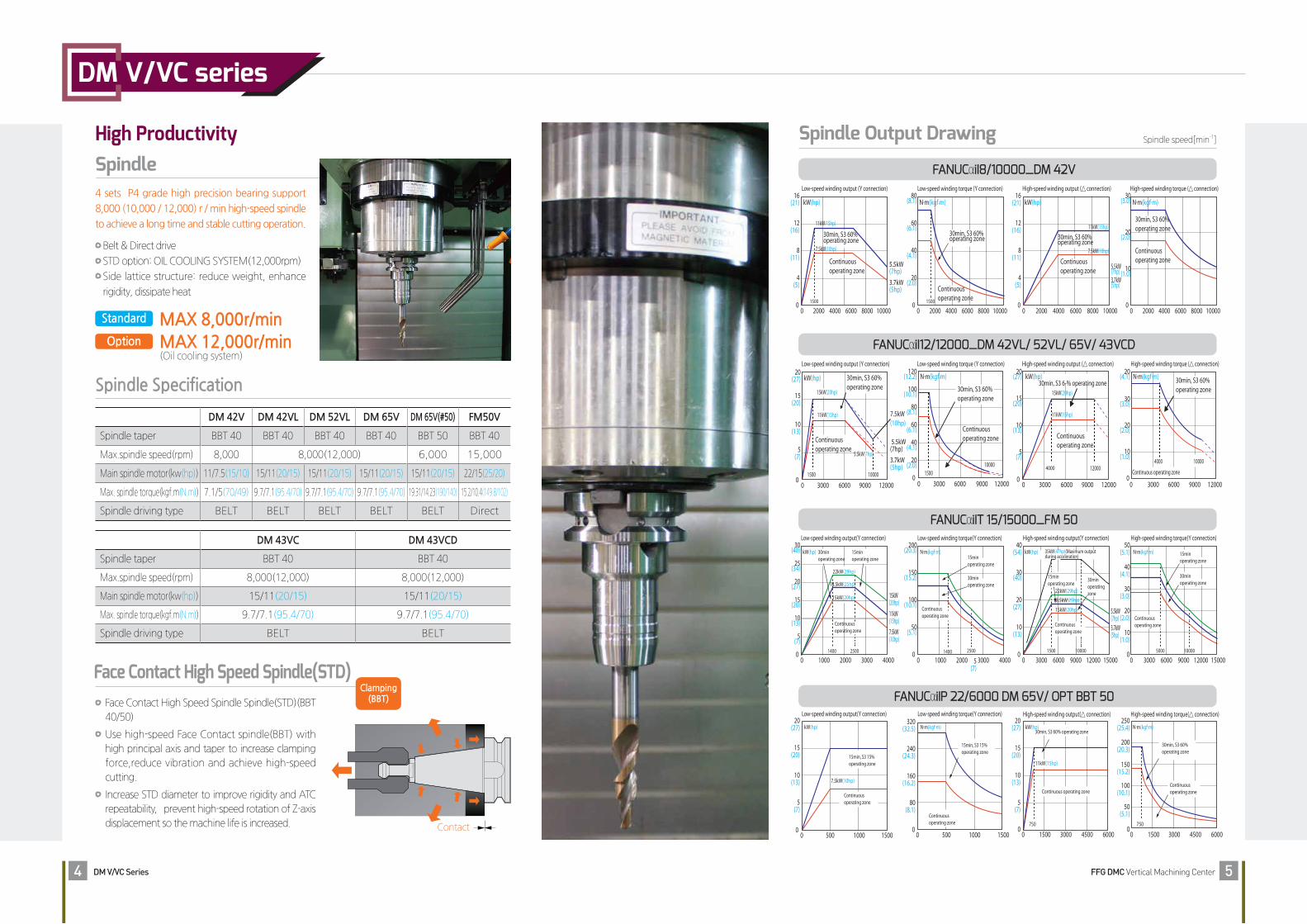
High ProductivitySpindle
Spindle Specification
Spindle Output Drawing
FANUCαiI8/10000_DM 42V
Face Contact High Speed Spindle(STD) Face Contact High Speed Spindle Spindle(STD)(BBT
40/50)
Use high-speed Face Contact spindle(BBT) with
high principal axis and taper to increase clamping
force,reduce vibration and achieve high-speed
cutting.
Increase STD diameter to improve rigidity and ATC
repeatability,prevent high-speed rotation of Z-axis
displacement so the machine life is increased. Contact
4 sets P4 grade high precision bearing support
8,000 (10,000 / 12,000) r / min high-speed spindle
to achieve a long time and stable cutting operation.
Belt & Direct drive
STD option: OIL COOLING SYSTEM(12,000rpm)
Side lattice structure: reduce weight, enhance
rigidity, dissipate heat
DM 42V DM 42VL DM 52VL DM 65V DM 65V(#50) FM50V
Spindle taper BBT 40 BBT 40 BBT 40 BBT 40 BBT 50 BBT 40
Max.spindle speed(rpm) 8,000 8,000(12,000) 6,000 15,000
Main spindle motor(kw(hp)) 11/7.5(15/10) 15/11(20/15) 15/11(20/15) 15/11(20/15) 15/11(20/15) 22/15(25/20)
Max. spindle torque(kgf.m(N.m)) 7.1/5(70/49) 9.7/7.1(95.4/70) 9.7/7.1(95.4/70) 9.7/7.1(95.4/70) 19.31/14.23(190/140) 15.2/10.4(149.8/102)
Spindle driving type BELT BELT BELT BELT BELT Direct
DM 43VC DM 43VCD
Spindle taper BBT 40 BBT 40
Max.spindle speed(rpm) 8,000(12,000) 8,000(12,000)
Main spindle motor(kw(hp)) 15/11(20/15) 15/11(20/15)
Max. spindle torque(kgf.m(N.m)) 9.7/7.1(95.4/70) 9.7/7.1(95.4/70)
Spindle driving type BELT BELT
MAX 8,000r/minMAX 12,000r/min(Oil cooling system)
Low-speed winding output (Y connection)
kW(hp)
15kW(20hp)
30min, S3 60%operating zone
11kW(15hp)
Continuousoperating zone
20(27)
15(20)
10(13)
5(7)
1500
3000 6000 9000 12000
3.7kW(5hp)
5.5kW(7hp)
7.5kW(10hp)
5.5kW(7hp)
10000
00
Low-speed winding torque (Y connection)
N.m(kgf.m)120
(12.2)
100(10.1)
30min, S3 60%operating zone
Continuousoperating zone
80(8.1)
60(6.1)
40(4.1)
20(2.0)
15000
0 3000 6000 9000 12000
10000
High-speed winding output (△ connection)
30min, S3 6-% operating zone
Continuousoperating zone
4000
kW(hp)20
(27)
15(20)
15kW(20hp)
11kW(15hp)
10(13)
5(7)
3000 6000 9000 12000
12000
00
High-speed winding output (△ connection)
11kW(15hp)
5.5kW(7hp)3.7kW(5hp)
7.5kW(10hp)
00 2000
Continuousoperating zone
30min, S3 60%operating zone
4000 6000 8000 10000
kW(hp)
Low-speed winding torque (Y connection)80
(8.1)
60(6.1)
40(4.1)
20(2.0)
00 2000
1500
Continuousoperating zone
30min, S3 60%operating zone
4000 6000 8000 10000
N.m(kgf.m)
Low-speed winding output (Y connection)16
(21)
12(16)
11kW(15hp)
5.5kW(7hp)3.7kW(5hp)
7.5kW(10hp)8(11)
4(5)
16(21)
12(16)
8(11)
4(5)
00 2000
1500
Continuousoperating zone
30min, S3 60%operating zone
4000 6000 8000 10000
kW(hp)
High-speed winding torque (△ connection)
Continuous operating zone
30min, S3 60%operating zone
N.m(kgf.m)20
(4.1)
30(3.0)
20(2.0)
10(1.0)
00 3000
4000 10000
6000 9000 12000
High-speed winding torque (△ connection)30
(3.0)
20(2.0)
10(1.0)
00 2000
Continuousoperating zone
30min, S3 60%operating zone
4000 6000 8000 10000
N.m(kgf.m)
20(27)
15(20)
10(13) 7.5kW(10hp)
5(7)
00 500 1000 1500
Low-speed winding output(Y connection)
Continuousoperating zone
15min, S3 15%operating zone
kW(hp)20
(27)
15(20)
10(13)
5(7)
00 1500
750
11kW(15hp)
3000 4500 6000
30min, S3 60% operating zone
Continuous operating zone
High-speed winding output(△ connection)
kW(hp)320
(32.5)
240(24.3)
160(16.2)
80(8.1)
00 500 1000 1500
Low-speed winding torque(Y connection)
Continuousoperating zone
15min, S3 15%operating zone
N.m(kgf.m)250
(25.4)
200(20.3)
150(15.2)
100(10.1)
50(5.1)
00 1500
750
3000 4500 6000
30min, S3 60% operating zone
Continuous operating zone
High-speed winding torque(△ connection)
N.m(kgf.m)
30(40)
10(13)
15(20)
20(27)
25(34) 22kW(29hp)
15kW(20hp)
Low-speed winding output(Y connection)
11kW(15hp)
15kW(20hp)
7.5kW(10hp)
18.5kW(25hp)
5(7)
00 1000
1400
Continuousoperating zone
30minoperating zone
15minoperating zone
2000 3000 40002500
kW(hp)40
(54)
30(40)
20(27)
10(13)
High-speed winding output(Y connection)
5.5kW(7hp)3.7kW(5hp)
18.5kW(25hp)22kW(29hp)
15kW(20hp)
00 3000
1500
Continuousoperating zone
6000 9000 12000 1500010000
30minoperatingzone
15minoperating zone
35kW(47hp)(Maximum output during acceleration)
kW(hp)15minoperating zone
30minoperating zone
200(20.3)
150(15.2)
Low-speed winding torque(Y connection)
100(10.1)
50(5.1)
00 1000 2000
1400
Continuousoperating zone
400030002500
N.m(kgf.m)50
(5.1)
40(4.1)
High-speed winding torque(Y connection)
30(3.0)
20(2.0)
10(1.0)
00 3000
5000
Continuousoperating zone
30minoperating zone
6000 9000 12000 1500010000
15minoperating zone
N.m(kgf.m)
5(7)
Spindle speed[min-1]
FANUCαiI12/12000_DM 42VL/ 52VL/ 65V/ 43VCD
FANUCαiIP 22/6000 DM 65V/ OPT BBT 50
FANUCαiIT 15/15000_FM 50
Clamping(BBT)
Standard
Option
Page 4
DM V/VC series
FFG DMC Vertical Machining CenterDM V/VC Series6 7
AXIS
Table moving TYPE
Column moving TYPE
High ProductivityTool Magazine
ATC Specification
Detachable magazine
Use frame for a separate
magazine,tremor from ATC
and magazine won't pass to
machine so the machine can
keep it's high accuracy.
(T-T) 1.8 seconds
Tool to Tool 1.8 seconds,
chip to Chip 3.9 seconds,
fast tool changing can
minimize non-cutting
time.
Use high-speed Twin arm type (CAM type) tool changer as STD OPT to
achieve high productivity.
DM 42V DM 42VL DM 52VL DM 65V DM 65V(#50) FM 50V
Tool storage capacity 24EA 24EA(30,40) 24EA(30,40) 30(40) 24 30
Max. tool diameter [without adjacent](mm(inch))
Ø85[Ø125](Ø3.35[Ø4.92])
Ø85[Ø125](Ø3.35[Ø4.92])
Ø85[Ø125](Ø3.35[Ø4.92])
Ø85[Ø125](Ø3.35[Ø4.92])
Ø127[Ø200](Ø5[Ø7.87])
Ø85[Ø125](Ø3.35[Ø4.92])
Max. tool length 300mm(11.81") 300mm(11.81") 300mm(11.81") 300mm(11.81") 300mm(11.81") 300mm(11.81")
Max. tool weight 7kgf(15.43lbf) 7kgf(15.43lbf) 7kgf(15.43lbf) 7kgf(15.43lbf) 15kgf(33.07lbf) 7kgf(15.43lbf)
Method of tool selction MEMORY RANDOM MEMORY RANDOM MEMORY RANDOM MEMORY RANDOM MEMORY RANDOM MEMORY RANDOM
Tool changing timeT-T 1.8sec 1.8sec 1.8sec 1.8sec 2.45sec 1.5sec
C-C 3.9sec 3.9sec 3.9sec 3.9sec 5.5sec 4.2sec
DM 43VC DM 430VCD
Tool storage capacity 30EA(24,40) 30EA(24,40)
Max. tool diameter [without adjacent](mm(inch))
Ø85[Ø125](Ø3.35[Ø4.92]) Ø85[Ø125](Ø3.35[Ø4.92])
Max. tool length 300mm(11.81") 300mm(11.81")
Max. tool weight 7kgf(15.43lbf) 7kgf(15.43lbf)
Method of tool selction MEMORY RANDOM MEMORY RANDOM
Tool changing timeT-T 1.8sec 1.8sec
C-C 3.9sec 3.9sec
TWIN ARM TYPE(CAM type)
ALL AXES :High precision& pretension double anchor system.
Best-in-class rapid traverse speeds and wide machining area!
Machine is equipped with high speed, high
accuracy, high productivity guide ROLLER,to
maintained a stable accuracy under all conditions.
Use the Roller guideways as a OPT to achieve
powerful,high speed heaving cutting.
Rapid traverse rateDM 42V DM 42VL DM 52VL DM 65V DM 65V(#50) FM50V
X 48(1,889.76) 36(1,417.32) 36(1,417.32) 36(1,417.32) 36(1,417.32) 60(2,362.20)
Y 48(1,889.76) 36(1,417.32) 36(1,417.32) 36(1,417.32) 36(1,417.32) 60(2,362.20)
Z 36(1,417.32) 30(1,181.10) 30(1,181.10) 30(1,181.10) 30(1,181.10) 36(1,417.32)
Unit : m/min(ipm)
DM 42V DM 42VL DM 52VL DM 65V DM 65V(#50) FM50V
X 600(23.62) 765(30.12) 1,020(40.16) 1,280(50.39) 1,280(50.39) 800(31.50)
Y 420(16.54) 420(16.54) 520(20.47) 670(26.38) 670(26.38) 520(20.47)
Z 510(20.08) 510(20.08) 510(20.08) 640(25.20) 640(25.20) 510(20.08)
Unit : mm(inch)X/Y/Z Travel
Rapid traverse rate
Spacious working area.
DM 43VC DM 43VCD
X 48(1,889.76) 48(1,889.76)
Y 48(1,889.76) 48(1,889.76)
Z 36(1,417.32) 36(1,417.32)
Unit : m/min(ipm)
DM 43VC DM 43VCD
X 600(23.62) 600(23.62)
Y 430(16.93) 430(16.93)
Z 570(22.44) 570(22.44)
X/Y/Z Travel Unit : mm(inch)
Page 5
DM V/VC series
FFG DMC Vertical Machining CenterDM V/VC Series8 9
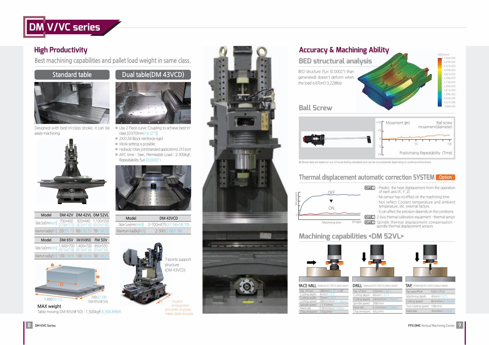
Accuracy & Machining AbilityBest machining capabilities and pallet load weight in same class. BED structural analysis
Ball Screw
Thermal displacement automatic correction SYSTEM
High Productivity
Designed with best-in-class stroke, it can be
easily machining.
Standard table
Model DM 42V DM 42VL DM 52VL
Table Size[mm(inch)]700×400
(27.56×15.75)920×440
(36.22×17.32)1,100×550(43.31×21.65)
Maximum load[kgf(lbf)] 250(551.15) 600(1,322.75) 700(1,543.21)
Model DM 65V DM 65V(#50) FM 50V
Table Size[mm(inch)]1,400×700(55.12×27.56)
1,400×700(55.12×27.56)
950×550(37.4×21.65)
Maximum load[kgf(lbf)] 1,500(3,306.89) 1,500(3,306.89) 700(1,543.21)
Use 2 Piece curvic Coupling to achieve best-in-
class [Ø370mm(14.57")]
2X3 LM Block reinforce rigid
Work setting is possible
Hydraulic rotary joint(standard applications) 2X3 port
APC time : 5sec, Permissible Load : 2-300kgf,
Repeatability 5㎛ (0.0002")
Dual table(DM 43VCD)
Model DM 43VCD
Table Size[mm(inch)] 2-700×475(27.56×18.70)
Maximum load[kgf(lbf)] 2-300(2-661.38)
MAX weightTable moving DM 65V(# 50) : 1,500kgf(3,306.89lbf)
Y
Z
X
1,400(55.12)700(27.56)
DM 65V(# 50) Same location
machining position
and center of gravity
makes stable structure
7-points support
structure
(DM 43VCD)
Machining capabilities <DM 52VL>
FACE MILL 〈Material〈JIS〉:S45C(Carbon steel)〉
Dia. of tool Ø80mm(3.15") x 6FCutting depth 3mm(0.12")Cutting width 70mm(2.76")Cutting speed 286mm/min(11.26ipm)Spindle speed 1,137r/minFeed rate 0.9mm/rev(0.036ipr)Chip emissions 210cc/min
DRILL 〈Material〈JIS〉:S45C(Carbon steel)〉
Dia. of tool Ø32mm(1.26")
Cutting depth 40mm(1.57")
Cutting speed 24mm/min(0.94ipm)
Spindle speed 268r/min
Feed rate 0.2mm/rev(0.008ipr)
Chip emissions 43cc/min
TAP. 〈Material〈JIS〉:S45C(Carbon steel)〉
Tap spec/Pitch M24 x P3.0
Machining depth 40mm(1.57")
Cutting speed 8mm/min(0.31ipm)
Tool rotating speed 106r/min
Feed rate 3mm/rev(0.12ipr)
BED structure (5㎛ (0.0002") than
generated) doesn't deform when
the load is 6Ton(13,228lbs)
OPT 1 - Predict the heat displacement from the operation of each axis (X, Y, Z).
- No sensor has no effect on the machining time.
- Not reflect Coolant temperature and ambient temperature, etc. external factors.
- It can affect the precision depends on the conditions.
OPT 2 Z-Axis thermal calibration equipment - thermal sensor
OPT 3 Spindle thermal displacement compensation - spindle thermal displacement sensors
Machining time (Image)
0
Mo
vem
ent OFF
ON
▼
URES(mm)
- 5,432e-003
- 4,979e-003
- 4,527e-003
- 4,074e-003
- 3,621e-003
- 3,169e-003
- 2,716e-003
- 2,263e-003
- 1,811e-003
- 1,358e-003
- 9,053e-004
- 4,527e-004
- 1,000e-030
Movement (μm) Ball screw movement(diameter)
Positionaing Repeatability (Time)
+10
+5
0
5
10
50 100
Above data are based on our in-house testing standards and can be circumstantial depending on working environment.
Option
Page 6
DM V/VC series
FFG DMC Vertical Machining CenterDM V/VC Series10 11
① 1st step : Mesh filter
② 2nd step : Bucket mesh
③ 3rd step : Mesh filter
④ 4th step : Motor suction filter
Coolant
Chip
Flow
3 steps filter coolant tankEasy Clean-up & Prevent Coolant over flow
①
②
③
Chip conveyor
Coolant Tank
Chip conveyor Bucket
Machine ④
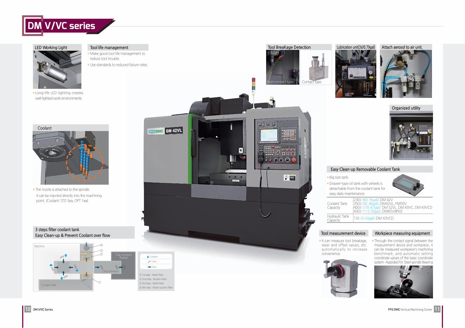
The nozzle is attached to the spindle.
It can be injected directly into the machining
point. (Coolant: STD 3ea, OPT 1ea)
Coolant
Long-life LED lighting creates
well-lighted work environments.
LED Working Light Tool life management Make good tool life management to
reduce tool trouble.
Use standards to reduced failure rates.
Lubrication unit(3ℓ/0.79gal)Tool BreaKage Detection
Non-contact type Contact type
Attach aerosol to air unit.
Workpiece measuring equipment
Through the contact signal between the measurement device and workpiece, it can be measured workpiece's machining benchmark, and automatic setting coordinate values of the basic coordinate system -Applided for Steel spindle Bearing
Tool measurement device
It can measure tool breakage, wear and offset values, etc. automatically to increase convenience.
Easy Clean-up Removable Coolant Tank
Big size tank
Drawer-type oil tank with wheels is
detachable from the coolant tank for
easy daily maintenance.
Coolant Tank Capacity
230ℓ (60.76gal): DM 42V350ℓ (92.46gal): DM42VL, FM50V400ℓ (105.67gal): DM 52VL, DM 43VC, DM 43VCD430ℓ (113.59gal): DM65V(#50)
Hydraulic Tank Capacity
13ℓ (3.43gal): DM 43VCD
Organized utility
Page 7
DM V/VC series
FFG DMC Vertical Machining CenterDM V/VC Series12 13
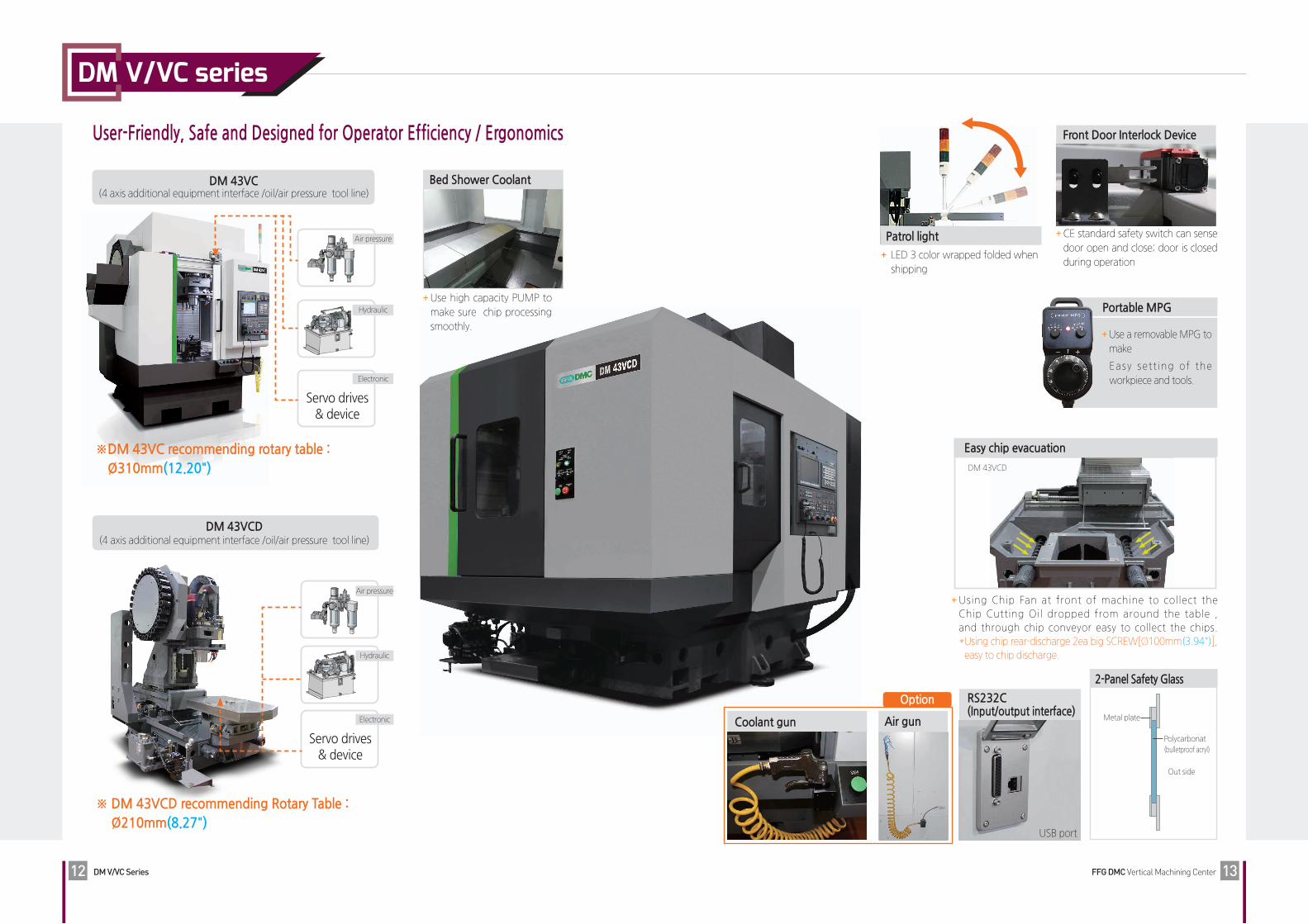
User-Friendly, Safe and Designed for Operator Efficiency / Ergonomics
Coolant gun Air gun
Use high capacity PUMP to
make sure chip processing
smoothly.
Bed Shower Coolant
Using Chip Fan at front of machine to collect the
Chip Cutting Oil dropped from around the table ,
and through chip conveyor easy to collect the chips.
* Using chip rear-discharge 2ea big SCREW[Ø100mm(3.94")],
easy to chip discharge.
Easy chip evacuation
DM 43VCD
DM 43VC(4 axis additional equipment interface /oil/air pressure tool line)
Electronic
Servo drives & device
Air pressure
Hydraulic
※ DM 43VC recommending rotary table : Ø310mm(12.20")
DM 43VCD(4 axis additional equipment interface /oil/air pressure tool line)
Air pressure
Hydraulic
Electronic
Servo drives & device
※ DM 43VCD recommending Rotary Table : Ø210mm(8.27")
CE standard safety switch can sense
door open and close; door is closed
during operation
Front Door Interlock Device
LED 3 color wrapped folded when
shipping
Patrol light
Use a removable MPG to
make
Easy set t ing of the
workpiece and tools.
Portable MPG
RS232C(Input/output interface)
USB port
2-Panel Safety Glass
Polycarbonat
(bulletproof acryl)
Out side
Metal plate
Option
Page 8
Robot systemGantry loader system
DM V/VC series
FFG DMC Vertical Machining CenterDM V/VC Series14 15
Various standard options and Specialized features for customers
Automatic power-off Fixture interface
StandardType
Variety of Jig Setup
Example
Other soft options selection
Tool box, Working light(LED), Hydraulic unit, Door interlock, Cutting oil supplying device, Work light, Leveling
bolt&place, Splash guard, 3-step patrol light, Auto Lubrication Unit, Portable MPG handle, RS232C+USB Port
Option Equipment
Index Jig Index Jig & Tailstock Jig Multi Jig Multi Jig
Wide table DM 65V(#50)
400(
15.7
5)
400(
15.7
5)
100
(3.9
4)
100
(3.9
4)
100
(3.9
4)
100
(3.9
4)
Unit : mm(inch)Standard
700(27.56)Wide
800(31.50)
Spindle
Coolant Tank
Line Filter(100 Mesh)
Spindle hollow Coolant
Air zero(Workpiece contact surface check equipment)
Auto front door(430C)
Coolant gun(with SOL/Without sensor)
Oil Mist Collector Oil Skimmer(Belt type)
Column[200mm(7.87”)]
Linear scale(High precision position control)
Oil Skimmer(Disk type)
Point Sensor(High precision position control)
FLOAT SWITCHDISK TYPEOIL SKIMMER
TOP cover
Multi counter
Automation & Variable Options
Chip bucket
230ℓ (60.76gal) (Swing)
300ℓ (79.25gal) (Swing)
300ℓ (79.25gal) (Fork lift)
380ℓ (100.38gal) (Fork lift)
440ℓ (116.23gal) (Fork lift)
Page 9
DM V/VC series
FFG DMC Vertical Machining CenterDM V/VC Series16 17
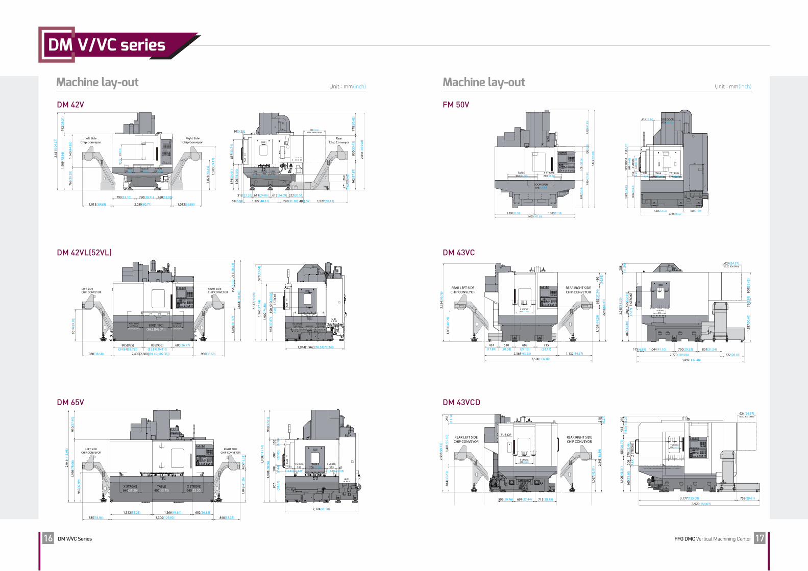
Machine lay-outMachine lay-out Unit : mm(inch)Unit : mm(inch)
2,53
7(99
.88)
1,96
2(77
.24)
575(
22.6
4)
1,90
2(74
.88)
962(
37.8
7)15
0(5.
91)
510(
20.0
8)Z
STRO
KE
1,944[1,962](76.54[77.24])
Y/Z STROKE210[260]
(8.27[10.24])
Y/Z STROKE210[260]
(8.27[10.24])440[550]
(17.32[21.65])
Right SideChip Conveyor
Left SideChip Conveyor
1,013(39.88) 1,013(39.88)2,050(80.71)
2,65
1(10
4.37
)
1,50
3(59
.17)
1,02
5(40
.35)1,
909(
75.1
6)74
2(29
.21)
1,14
0(44
.88)
769(
30.2
8)
90(3
.54)
510(
20.0
8)
X STROKE310(12.20)
TABLE SIZE700(27.56)
X STROKE310(12.20)
790(31.10) 780(30.71) 480(18.90)
857(
33.7
4)87
4(34
.41)
760(29.92)(ELEC, BOX OPEN)
890(
35.0
4)
10(0.39)
2,64
1(10
3.98
)
900(
35.4
3)96
2(37
.87)
269
(10.59
)27
1(10
.67)
778(
30.6
3)
68(2.68) 1,227(48.31) 40(1.57)790(31.10) 1,527(60.12)
522(20.55)612(24.09)611(24.06)312(12.28)
Y STROKE210
(8.27)
Y STROKE210
(8.27)
TABLE SIZE400
(15.75)
RearChip Conveyor
1,04
8(41
.26)
465(
18.3
1)
848(33.39)885(34.84) 3,300(129.92)
1,266(49.84) 682(26.85)1,352(53.23)
2,94
6(11
5.98
)
1,99
8(78
.66)
950(
37.4
0)
965(
37.9
9)
RIGHT SIDECHIP CONVEYOR
LEFT SIDECHIP CONVEYOR
TABLE400(15.75)
X STROKE640(25.20)
X STROKE640(25.20)
2,93
8(11
5.67
)
1,99
8(78
.66)
940(
37.0
1)
967
(38.
07)
687
(27.
05)
155
(6.1
0)18
9(7
.44)
2,324(91.50)
TABLE700(27.56)
Y STROKE335
(13.19)277
(10.91)65
(2.56)
Y STROKE335
(13.19)
2,61
8(10
3.07
)
717(
28.2
3)15
5(6.
10)
1,06
6(41
.97)
1014
(39.
92)
980(38.58) 980(38.58)2,400[2,600](94.49[102.36])
885[985](34.84[38.78])
835[935](32.87[36.81])
680(26.77)
920[1,100](36.22[43.31])
X/Z STROKE382.5[510]
(15.06[20.08])
X/Z STROKE382.5[510]
(15.06[20.08])
RIGHT SIDECHIP CONVEYOR
LEFT SIDECHIP CONVEYOR
DM 42V
DM 42VL(52VL)
DM 65V DM 43VCD
692(
27.2
4)1,
124(
44.2
5)43
0(1
6.93
)22
46(8
8.43
)
2,53
4(99
.76)
1,03
1(40
.59)
3,500(137.80)
2,368(93.23) 1,132(44.57)
715(28.15)
689(27.13)
510(20.08)
454(17.87)
X STROKE600(23.62)
REAR RIGHT SIDECHIP CONVEYOR
REAR LEFT SIDECHIP CONVEYOR
288
(11.
34)
2,24
5(88
.39)
570(
22.4
4)Z
STRO
KE20
0(7
.87)
860(
33.8
6)
900(
35.4
3)1,
287(
50.6
7)75
(2.9
5)
3,492(137.48)
722(28.43)2,770(109.06)
801(31.54)1,044(41.10)175(6.89) 750(29.53)
624(24.57)(ELEC. BOX OPEN)
Y STROKE417
210
(8.2
7)2,
245(
88.3
9)
1,06
7(42
.01)
288
(11.
34)
844(
33.2
3)1,
401(
55.1
6)
2,53
3(99
.72)
1132(44.57)1,914(75.35)454(17.87)966(38.03)
502(19.76)
SUB OP
697(27.44) 715(28.15)
REAR RIGHT SIDECHIP CONVEYOR
REAR LEFT SIDECHIP CONVEYOR
X STROKE600(23.62)
210
(8.2
7)46
5(1
8.31
)68
0(26
.77)
1,10
0(43
.31)
570(
22.4
4)Z
STRO
KE20
0(7
.87)
860(
33.8
6)
752(29.61)3,177(125.08)
3,929(154.69)
624(24.57)(ELEC. BOX OPEN)
Y STROKE430(16.93)
FM 50V
DM 43VC
415(16.34)
130(
5.12
)SI
DE
DO
OR
849(
33.4
3)1,
002(
39.4
5)
1032
(40.
63)
150
(5.9
1)Z
STRO
KE51
0(20
.08)
Y STROKE520(20.47)
260(10.24)
TABLE550(21.65)
1,385(54.53) 800(31.50)2,185(86.02)
SIDE DOOR870(34.25)
1,19
5(47
.05)
150(
5.91
)1,
824(
71.8
1)
1081
(42.
56)
899(
35.3
9)
DOOR OPEN 846(33.31)
1,300(51.18)1,300(51.18)2,600(102.36)
TABLE 950(37.40)
X STROKE 800(31.50)
3,17
5(12
5.00
)
Page 10
Ø15
19 0-0.35
60
25 35
16 28 7
3 3 4
4 5
C2
R 0.5
C1R2
M16x2 6
4
Ø23
Ø10
16.1
(0.6
3)
22.6(0.89) 0-0.2 22.6(0.89) 0
-0.2
(Ø25
.3(1
.00)
)
Ø17
(0.6
7)H
8
(Ø19
(0.7
5))
25(0.98)16.6(0.65)±0.1
2(0.08) 65.4(2.57)
M16
92.4(3.64)
21(0.83)
30(1.18)8(0.31)
3(0.12)
10(0.39)
60˚ 45̊
30̊Ø63
(2.4
8)Ø
53(2
.09)
7/24 TAPER
TOOL LENGTH(L)
R8.05
R 0.5
Ø4 HoldThru Coolant
Ø14
Ø44
.45
Ø13
Ø17
h7
R 0.08
19(0.75) 0-0.35
2(0.08)4(0.16)
23(0.91)
29(1.14)25(0.98)
M16x2M16x2
Ø23
(0.9
1)Ø
17(0
.67)
Ø7(
0.28
)
15˚
Ø17
(0.6
7)
Ø14
(0.5
5)
Ø19
(0.7
5)30˚
MACHINE SPECIFICATIONDM V/VC series
FFG DMC Vertical Machining CenterDM V/VC Series18 19
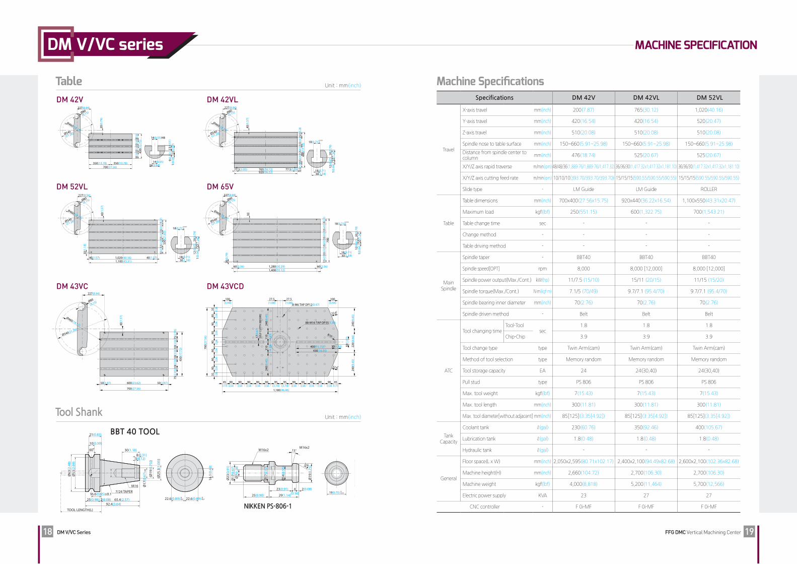
Machine SpecificationsTable Unit : mm(inch)
Tool ShankUnit : mm(inch)
D M V / V C series
NIKKEN PS-806-1
14(0.55)H8
24(0.94)14(0.55)
1(0.
04)
22(0
.87)
9(0.
35)
13(0
.51)
700(27.56)350(13.78) 350(13.78)
400(
15.7
5)100
(3.94)1
00(3.9
4)100(
3.94)1
00(3.9
4)
20(0
.79)
227(8.94)
Ø460(18.11)Ø540(21.26)
Ø80(3.15)
600(23.62)50(1.97) 50(1.97)
700(27.56)
450(
17.7
2)
40(1
.57)
227(8.94)
Ø460(18.11)
Ø540(21.26)
Ø80
(3.15)
75(2
.95)
75(2
.95)
100(
3.94)
100(
3.94)
100(
3.94)
700(
27.5
6)
35 (1.38
)35 (1.
38)
90 (3.54
)90 (3.
54)
90 (3.54
)90 (3.
54)
90 (3.54
)90 (3.
54)
90 (3.54
)
220(
8.66
)24
0(9.
45)22.6̊
22.6̊
240(
9.45
)
50(1
.97)17
(0.6
7)(S
ELF
CUTT
’H B
EFO
RE)
110
(4.3
3)11
0(4
.33)
240(
9.45
)24
0(9.
45)
R10
100(3.94)
88-M16 TAP DP35(1.38)
8-M6 TAP DP12(0.47)
27.5(1.08)
27.5(1.08)
30(1.18)400(15.75)430(16.93)
100(3.94)
90(3.54)
45(1.77)
45(1.77)
90(3.54)
90(3.54)
90(3.54)
90(3.54)
90(3.54)
90(3.54)
90(3.54)
90(3.54)
90(3.54)
95(3.74)
95(3.74)
1,180(46.46)
30(1.18)
18(0.71)+0.018 0
18(0.71)
32(1
.26)
1(0.
04)
20(0
.79)
12(0
.47)
440(
17.3
2)32
.5(1.2
8)32
.5(1.2
8)12
5(4.92
)12
5(4.92
)12
5(4.92
)
40(1
.57)
227(8.94)
Ø460(18.11)Ø540(21.26)
Ø80(3.15)
77.5(3.05) 765(30.12)920(36.22)
77.5(3.05)
1,020(40.16)40(1.57) 40(1.57)1,100(43.31)
550(
21.6
5)
40(1
.57)
227(8.94)
Ø460(18.11)Ø540(21.26)
Ø80(3.15)
73(2.8
7)102
(4.02)
125(4
.92)
125(4
.92)
125(4
.92)
125(4
.92)
115(4
.53)
125(4
.92)12
5(4.92
)125(4
.92)
30(1
.18)
700
30
227(8.94)
Ø460(18.11)Ø540(21.26)
Ø80(3.15)
1,400(55.12)1,280(50.39)60(2.36) 60(2.36)
20(0
.79)
85(3.
35)
30(1.18)
18(0.71)+0.018 0
18(0.71)
32(1
.26)
1(0.
04)
20(0
.79)
12(0
.47)
30(1.18)
18(0.71)+0.018 0
18(0.71)
32(1
.26)
1(0.
04)
20(0
.79)
12(0
.47)
DM 42V DM 42VL
14(0.55)H8
24(0.94)14(0.55)
1(0.
04)
22(0
.87)
9(0.
35)
13(0
.51)
700(27.56)350(13.78) 350(13.78)
400(
15.7
5)100
(3.94)1
00(3.9
4)100(
3.94)1
00(3.9
4)
20(0
.79)
227(8.94)
Ø460(18.11)Ø540(21.26)
Ø80(3.15)
600(23.62)50(1.97) 50(1.97)
700(27.56)
450(
17.7
2)
40(1
.57)
227(8.94)
Ø460(18.11)
Ø540(21.26)
Ø80
(3.15)
75(2
.95)
75(2
.95)
100(
3.94)
100(
3.94)
100(
3.94)
700(
27.5
6)
35 (1.38
)35 (1.
38)
90 (3.54
)90 (3.
54)
90 (3.54
)90 (3.
54)
90 (3.54
)90 (3.
54)
90 (3.54
)
220(
8.66
)24
0(9.
45)22.6̊
22.6̊
240(
9.45
)
50(1
.97)17
(0.6
7)(S
ELF
CUTT
’H B
EFO
RE)
110
(4.3
3)11
0(4
.33)
240(
9.45
)24
0(9.
45)
R10
100(3.94)
88-M16 TAP DP35(1.38)
8-M6 TAP DP12(0.47)
27.5(1.08)
27.5(1.08)
30(1.18)400(15.75)430(16.93)
100(3.94)
90(3.54)
45(1.77)
45(1.77)
90(3.54)
90(3.54)
90(3.54)
90(3.54)
90(3.54)
90(3.54)
90(3.54)
90(3.54)
90(3.54)
95(3.74)
95(3.74)
1,180(46.46)
30(1.18)
18(0.71)+0.018 0
18(0.71)
32(1
.26)
1(0.
04)
20(0
.79)
12(0
.47)
440(
17.3
2)32
.5(1.2
8)32
.5(1.2
8)12
5(4.92
)12
5(4.92
)12
5(4.92
)
40(1
.57)
227(8.94)
Ø460(18.11)Ø540(21.26)
Ø80(3.15)
77.5(3.05) 765(30.12)920(36.22)
77.5(3.05)
1,020(40.16)40(1.57) 40(1.57)1,100(43.31)
550(
21.6
5)
40(1
.57)
227(8.94)
Ø460(18.11)Ø540(21.26)
Ø80(3.15)
73(2.8
7)102
(4.02)
125(4
.92)
125(4
.92)
125(4
.92)
125(4
.92)
115(4
.53)
125(4
.92)12
5(4.92
)125(4
.92)
30(1
.18)
700
30
227(8.94)
Ø460(18.11)Ø540(21.26)
Ø80(3.15)
1,400(55.12)1,280(50.39)60(2.36) 60(2.36)
20(0
.79)
85(3.
35)
30(1.18)
18(0.71)+0.018 0
18(0.71)
32(1
.26)
1(0.
04)
20(0
.79)
12(0
.47)
30(1.18)
18(0.71)+0.018 0
18(0.71)
32(1
.26)
1(0.
04)
20(0
.79)
12(0
.47)
DM 52VL DM 65V
14(0.55)H8
24(0.94)14(0.55)
1(0.
04)
22(0
.87)
9(0.
35)
13(0
.51)
700(27.56)350(13.78) 350(13.78)
400(
15.7
5)100
(3.94)1
00(3.9
4)100(
3.94)1
00(3.9
4)
20(0
.79)
227(8.94)
Ø460(18.11)Ø540(21.26)
Ø80(3.15)
600(23.62)50(1.97) 50(1.97)
700(27.56)
450(
17.7
2)
40(1
.57)
227(8.94)
Ø460(18.11)
Ø540(21.26)
Ø80
(3.15)
75(2
.95)
75(2
.95)
100(
3.94)
100(
3.94)
100(
3.94)
700(
27.5
6)
35 (1.38
)35 (1.
38)
90 (3.54
)90 (3.
54)
90 (3.54
)90 (3.
54)
90 (3.54
)90 (3.
54)
90 (3.54
)
220(
8.66
)24
0(9.
45)22.6̊
22.6̊
240(
9.45
)
50(1
.97)17
(0.6
7)(S
ELF
CUTT
’H B
EFO
RE)
110
(4.3
3)11
0(4
.33)
240(
9.45
)24
0(9.
45)
R10
100(3.94)
88-M16 TAP DP35(1.38)
8-M6 TAP DP12(0.47)
27.5(1.08)
27.5(1.08)
30(1.18)400(15.75)430(16.93)
100(3.94)
90(3.54)
45(1.77)
45(1.77)
90(3.54)
90(3.54)
90(3.54)
90(3.54)
90(3.54)
90(3.54)
90(3.54)
90(3.54)
90(3.54)
95(3.74)
95(3.74)
1,180(46.46)
30(1.18)
18(0.71)+0.018 0
18(0.71)
32(1
.26)
1(0.
04)
20(0
.79)
12(0
.47)
440(
17.3
2)32
.5(1.2
8)32
.5(1.2
8)12
5(4.92
)12
5(4.92
)12
5(4.92
)
40(1
.57)
227(8.94)
Ø460(18.11)Ø540(21.26)
Ø80(3.15)
77.5(3.05) 765(30.12)920(36.22)
77.5(3.05)
1,020(40.16)40(1.57) 40(1.57)1,100(43.31)
550(
21.6
5)
40(1
.57)
227(8.94)
Ø460(18.11)Ø540(21.26)
Ø80(3.15)
73(2.8
7)102
(4.02)
125(4
.92)
125(4
.92)
125(4
.92)
125(4
.92)
115(4
.53)
125(4
.92)12
5(4.92
)125(4
.92)
30(1
.18)
700
30
227(8.94)
Ø460(18.11)Ø540(21.26)
Ø80(3.15)
1,400(55.12)1,280(50.39)60(2.36) 60(2.36)
20(0
.79)
85(3.
35)
30(1.18)
18(0.71)+0.018 0
18(0.71)
32(1
.26)
1(0.
04)
20(0
.79)
12(0
.47)
30(1.18)
18(0.71)+0.018 0
18(0.71)
32(1
.26)
1(0.
04)
20(0
.79)
12(0
.47)
DM 43VC DM 43VCD
BBT 40 TOOL
Specifications DM 42V DM 42VL DM 52VL
Travel
X-axis travel mm(inch) 200(7.87) 765(30.12) 1,020(40.16)
Y-axis travel mm(inch) 420(16.54) 420(16.54) 520(20.47)
Z-axis travel mm(inch) 510(20.08) 510(20.08) 510(20.08)
Spindle nose to table surface mm(inch) 150~660(5.91~25.98) 150~660(5.91~25.98) 150~660(5.91~25.98)
Distance from spindle center to column
mm(inch) 476(18.74) 525(20.67) 525(20.67)
X/Y/Z axis rapid traverse m/min(ipm) 48/48/36(1,889.76/1,889.76/1,417.32) 36/36/30(1,417.32x1,417.32x1,181.10) 36/36/30(1,417.32x1,417.32x1,181.10)
X/Y/Z axis cutting feed rate m/min(ipm) 10/10/10(393.70/393.70/393.70) 15/15/15(590.55/590.55/590.55) 15/15/15(590.55/590.55/590.55)
Slide type - LM Guide LM Guide ROLLER
Table
Table dimensions mm(inch) 700x400(27.56x15.75) 920x440(36.22x16.54) 1,100x550(43.31x20.47)
Maximum load kgf(lbf) 250(551.15) 600(1,322.75) 700(1,543.21)
Table change time sec - - -
Change method - - - -
Table driving method - - - -
Main Spindle
Spindle taper - BBT40 BBT40 BBT40
Spindle speed[OPT] rpm 8,000 8,000 [12,000] 8,000 [12,000]
Spindle power output(Max./Cont.) kW(hp) 11/7.5 (15/10) 15/11 (20/15) 11/15 (15/20)
Spindle torque(Max./Cont.) N.m(kgf·m) 7.1/5 (70/49) 9.7/7.1 (95.4/70) 9.7/7.1 (95.4/70)
Spindle bearing inner diameter mm(inch) 70(2.76) 70(2.76) 70(2.76)
Spindle driven method - Belt Belt Belt
ATC
Tool changing timeTool-Tool
sec1.8 1.8 1.8
Chip-Chip 3.9 3.9 3.9
Tool change type type Twin Arm(cam) Twin Arm(cam) Twin Arm(cam)
Method of tool selection type Memory random Memory random Memory random
Tool storage capacity EA 24 24(30,40) 24(30,40)
Pull stud type PS 806 PS 806 PS 806
Max. tool weight kgf(lbf) 7(15.43) 7(15.43) 7(15.43)
Max. tool length mm(inch) 300(11.81) 300(11.81) 300(11.81)
Max. tool diameter[without adjacent] mm(inch) 85[125](3.35[4.92]) 85[125](3.35[4.92]) 85[125](3.35[4.92])
Tank Capacity
Coolant tank ℓ(gal) 230(60.76) 350(92.46) 400(105.67)
Lubrication tank ℓ(gal) 1.8(0.48) 1.8(0.48) 1.8(0.48)
Hydraulic tank ℓ(gal) - - -
General
Floor space(L x W) mm(inch) 2,050x2,595(80.71x102.17) 2,400x2,100(94.49x82.68) 2,600x2,100(102.36x82.68)
Machine height(H) mm(inch) 2,660(104.72) 2,700(106.30) 2,700(106.30)
Machine weight kgf(lbf) 4,000(8,818) 5,200(11,464) 5,700(12,566)
Electric power supply KVA 23 27 27
CNC controller - F 0i-MF F 0i-MF F 0i-MF
Page 11
MACHINE SPECIFICATIONDM V/VC series
Machine Specifications Machine Specifications
FFG DMC Vertical Machining CenterDM V/VC Series20 21
Specifications DM 65V DM 65V(#50) FM 50V
Travel
X-axis travel mm(inch) 1,280(50.39) 1,280(50.39) 800(31.50)
Y-axis travel mm(inch) 670(26.38) 670(26.38) 520(20.47)
Z-axis travel mm(inch) 640(25.20) 640(25.20) 510(20.08)
Spindle nose to table surface mm(inch) 150~790(5.51~30.71) 150~790(5.51~30.71) 150~660(5.91~25.98)
Distance from spindle center to column
mm(inch) 707(27.83) 707(27.83) 560(22.05)
X/Y/Z axis rapid traverse m/min(ipm) 36/36/30(1,417.32x1,417.32x1,181.10) 36/36/30(1,417.32x1,417.32x1,181.10) 60/60/36(2,362.20/2,362.20/1,417.32)
X/Y/Z axis cutting feed rate m/min(ipm) 15/15/15(590.55/590.55/590.55) 15/15/15(590.55/590.55/590.55) 30/30/16(1,181.10/1,181.10/629.92)
Slide type - ROLLER ROLLER ROLLER
Table
Table dimensions mm(inch) 1,400x700(55.12x27.56) 1,400x700(55.12x27.56) 950x550(37.40x21.65)
Maximum load kgf(lbf) 1,500(3,306.89) 1,500(3,306.89) 700(1,543.21)
Table change time sec - - -
Change method - - - -
Table driving method - - - -
Main Spindle
Spindle taper - BBT40 BBT50 BBT40
Spindle speed[OPT] rpm 8,000 [12,000] 6,000 15,000
Spindle power output(Max./Cont.) kW(hp) 15/11 (20/15) 15/11 (20/15) 22/15 (30/20.1)
Spindle torque(Max./Cont.) N.m(kgf·m) 9.7/7.1 (95.4/70) 19.31/14.23(190/140) 15.2/10.4(149.8/102)
Spindle bearing inner diameter mm(inch) 70(2.76) 100(3.94) 70(2.76)(GREASE)
Spindle driven method - Belt BeltDirect
(Built-in)
ATC
Tool changing timeTool-Tool
sec1.8 2.45 1.5
Chip-Chip 3.9 5.5 4.2
Tool change type type Twin Arm(cam) Twin Arm(cam) Twin Arm(cam)
Method of tool selection type Memory random Memory random Memory random
Tool storage capacity EA 30(40) 24 30
Pull stud type PS 806 MAS403 P50T-1 PS 806
Max. tool weight kgf(lbf) 7(15.43) 15(33.07) 7(15.43)
Max. tool length mm(inch) 300(11.81) 300(11.81) 300(11.81)
Max. tool diameter[without adjacent] mm(inch) 85[125](3.35[4.92]) 127[200](5[7.87]) 85[125](3.35[4.92])
Tank Capacity
Coolant tank ℓ(gal) 430(113.59) 430(113.59) 350(92.46)
Lubrication tank ℓ(gal) 1.8(0.48) 1.8(0.48) 1.8(0.48)
Hydraulic tank ℓ(gal) - - -
General
Floor space(L x W) mm(inch) 3,300x2,350(129.92x92.52) 3,300x2,350(129.92x92.52) 2,600x2,200(102.36x86.61)
Machine height(H) mm(inch) 2,940(115.75) 2,940(115.75) 3,175(125.00)
Machine weight kgf(lbf) 7,500(16,534) 7,700(16,975) 7,500(16,534)
Electric power supply KVA 32 34 42
CNC controller - F 0i-MF F 0i-MF F 0i-MF
Specifications DM 43VC DM 43VCD
Travel
X-axis travel mm(inch) 600(23.62) 600(23.62)
Y-axis travel mm(inch) 430(16.93) 430(16.93)
Z-axis travel mm(inch) 570(22.44) 570(22.44)
Spindle nose to table surface mm(inch) 200~770(7.87~30.31) 200~770(7.87~30.31)
Distance from spindle center to column
mm(inch) 505(19.88) 505(19.88)
X/Y/Z axis rapid traverse m/min(ipm) 48/48/36(1,889.76/1,889.76/1,417.32) 48/48/36(1,889.76/1,889.76/1,417.32)
X/Y/Z axis cutting feed rate m/min(ipm) 15/15/15(590.55/590.55/590.55) 15/15/15(590.55/590.55/590.55)
Slide type - LM Guide LM Guide
Table
Table dimensions mm(inch) 700x450(27.55x17.71) 2-700x475(2-27.56x18.70)
Maximum load kgf(lbf) 1,000(2,204.59) 2-300(2-661.38)
Table change time sec - 5
Change method - - PACK & PINION
Table driving method - - HYD
Main Spindle
Spindle taper - BBT40 BBT40
Spindle speed[OPT] rpm 8,000 [12,000] 8,000 [12,000]
Spindle power output(Max./Cont.) kW(hp) 15/11(20.1/14.7) 15/11(20.1/14.7)
Spindle torque(Max./Cont.) kgf·m(N.m) 9.7/7.1(95.4/70) 9.7/7.1(95.4/70)
Spindle bearing inner diameter mm(inch) 70(2.76) 70(2.76)
Spindle driven method - Belt Belt
ATC
Tool changing timeTool-Tool
sec1.8 1.8
Chip-Chip 3.9 3.9
Tool change type type Twin Arm(cam) Twin Arm(cam)
Method of tool selection type Memory random Memory random
Tool storage capacity EA 30(24,40) 30
Pull stud type PS 806 PS 806
Max. tool weight kgf(lbf) 7(15.43) 7(15.43)
Max. tool length mm(inch) 300(11.81) 300(11.81)
Max. tool diameter[without adjacent] mm(inch) 85[125](3.35[4.92]) 85[125](3.35[4.92])
Tank Capacity
Coolant tank ℓ(gal) 400(105.67) 400(105.67)
Lubrication tank ℓ(gal) 3(0.79) 3(0.79)
Hydraulic tank ℓ(gal) - 13(3.43)
General
Floor space(L x W) mm(inch) 2,375x3,500(93.50x137.80) 2,500x3,940(98.43x155.12)
Machine height(H) mm(inch) 2,735(107.68) 2,735(107.68)
Machine weight kgf(lbf) 6,500(14,330) 7,000(15,432)
Electric power supply KVA 33 33
CNC controller - F 0i-MF F 0i-MF
Page 12
MACHINE SPECIFICATIONDM V/VC series
FFG DMC Vertical Machining CenterDM V/VC Series22 23
NC Specifications (FANUC F0i-MF) ○ : Standard, OPT. : Option, (!) : M type, (!!) : 2SO type
Item Specification 0iMF
AxesControl
Controlled axes 3(X,Y,Z)
Simultaneously controllable axes 4 axes
Positioning G00
Linear interpolation G01 3 axes
Circular interpolation G02, G03 2axes
Backlash compensation
Emergency stop / overtravel
Follow up
Least command increment 0.001mm / 0.0001"
Least input increment 0.001mm / 0.0001"
Machine lock All axes / Z axis
Mirror image
Position switch
Stored pitch error compensation
Pitch error offset compensation for each axis
Stored stroke check 1
Overtraval controlled by software
Interpolation & Feed Function
2nd reference point return G30
Circular interpolation G02, G03
Cylindrical interpolation G07.1
Dwell G04
Exact stop mode G09, G61 (mode)
Feed per minute mm/min
Feedrate override(10% increments) 0-200 %
Helical interpolation
Jog override (10% increments) 0-200 %
Linear interpolation G01
Manual handle feed (1 unit)
Manual handle feedrate 0.1 / 0.01 / 0.001 mm
Override cancle M48 / M49
Positioning G00
Rapid traverse override F0 (fine feed), 25 / 50 / 100 %
Reference position return G28
Reference position return check G27
Skip function G31
Spindle &M-code function
M-code function M 3 digits
Spindle orientation
Spindle serial output
Spindle speed command S5 digits
Spindle speed override (10% increments) 50-120%
Tool function
Cutter compensation G40, G41, G42
Number of tool offsets 400 ea
Tool length compensation G43, G44, G49
Tool life management
Tool number command T2 digits
Tool offset memory C Geometry / wear and length / Radius offset memory
Tool offset G45-G48
Programming & Editing function
Absolute / Incremental programming G90 / G91
Automatic coordinate system setting
Background editing
Canned cycle G73, G74, G76, G80-G89, G99
Circular interpolation by radius programming
Custom macro
Dcimal point input
Extemded part program editing
I/O interface RS-232C / LAN PORT
Extemded part program editing
Label skip
Item Specification 0iMF
Programming & Editing function
Local / Machine coordinate system G52 / G53
Maximum commandable value ± 99999.999mm/(± 9999.9999 inch)
No. of registered programs 400ea
Optional block skip
Optional stop M01
Part program storage length*1 512K byte
Playback
program number 04-digits
Program protect
Program stop / end M00 / M02, M30
Rigid tapping G84, G74
Sub program Up to 4 nesting
Tape code ISO / EIA Automatic discrimination
Thread cutting
Work coordinate system G54-G59
Others functions(Operation, setting
& display, etc)
3rd / 4th reference return
Additional work coordinate system G54.1 P1-48 (48 pairs)
AI APC(Advanced Preview Control) 20 block preview
Alarm display
Alarm history display
Automatic corner override G62
Clock function
Coordinate system rotation G68, G69
Cycle start / Feed hold
Display of PMC alarm message Message display when PMC alarm occurred
Dry run
Embedded Ethernet
Graphic display Tool path drawing
Help function
High speed skip function
Loadmeter display
Manual handle interruption
MDI / DISPLAY unit 8.4” or 10.4” Color LCD, keyboard for data input (small), soft-keys
Memory card interface
USB interface
Operation functions Tape / Memory / MDI / Manual
Operation history display
Optional angle chamfering / corner R
Polar coordinate command G15 / G16
Program restart
Programmable data input Tool offset and work offset are entered by G10, G11
Programmable mirror image G50.1 / G51.1
Run hour and part number display
Scaling G50, G51
Search function Sequence NO. / Program NO.
Self-diagnostic function
Servo setting screen
Single block
Single direction positioning G60
Stored stroke check 2,3
Optional ecifications
Additional controlled axes 5 axes in total
AICC(AI Contour Control) Ⅰ 40 block preview
Manual guide 200books preview
Dynamic graphic display (w/ 10.4” color LCD) Machining profile drawing
Fast data server
Fast ethernet
Manual guide


![[vc 1037 - listing.archiviolocation.com · [vc 1037] ARCHIVIOLOCATION.COM [vc 1037] ARCHIVIOLOCATION.COM [vc 1037] ARCHIVIOLOCATION.COM [vc 1037] ARCHIVIOLOCATION.COM. archivio location](https://static.documents.pub/doc/80x56/5fcd99d1df347e1ae154645c/vc-1037-vc-1037-archiviolocationcom-vc-1037-archiviolocationcom-vc-1037.jpg)


