ADJUSTING bERLinPro OPTICS TO COMMISSIONING NEEDS∗
B. Kuske† , M. McAteer, Helmholtz-Zentrum für Materialien und Energie, Berlin, Germany
AbstractbERLinPro is an Energy Recovery Linac (ERL) project
being set up at HZB, Berlin. During the turn of the project,many adaptations of the optics to changing hardware reali-ties and new challenges were necessary. Exemplary topicsare chosen for each of the three different machine parts: thediagnostics line, the Banana and the recirculator. In the di-agnostics line, the need to seek a quick understanding of themachine during commissioning and the low energy are thecentral concern. In the Banana, unwanted beam will dom-inate the performance. Commissioning of the recirculatorwill be realized with the super-conducting linac module fab-ricated for the Mainz ERL project MESA, as the bERLinProlinac is delayed. The Mainz linac will supply 60 % of theenergy planned. While the adopted optics shows similarparameters as the original 50 MeV optics, studies of longitu-dinal space charge and coherent synchrotron radiation showthat the lower energy leads to large emittance blow up dueto micro bunching and CSR effects.
INTRODUCTIONbERLinPro is an Energy Recovery Linac project close
to completion at HZB, Berlin, Germany, [1]. It is intendedas an experiment in accelerator physics, to pioneer the pro-duction of high current, low emittance beams in a fullysuper-conducting accelerator, including SRF gun, boosterand linac. The machine, with a length of roughly 80 m con-sists of three different independent sub-parts: the diagnosticsline, straight forward from the SRF gun and booster; the lowenergy part, including injector, merger, linac straight, splitterand dump line. This is called the Banana. In presence of alinac module, the beam would run through the recirculatorand be energy recovered before being led to the dump line,Fig. 1. Over the turn of the project different boundary con-ditions asked for optics adjustments and new challenges hadto be met. The paper describes examples of this work foreach machine part.
DIAGNOSTICS LINEThe diagnostics line consists of the 1.3 GHz, 1.4 cell, sin-
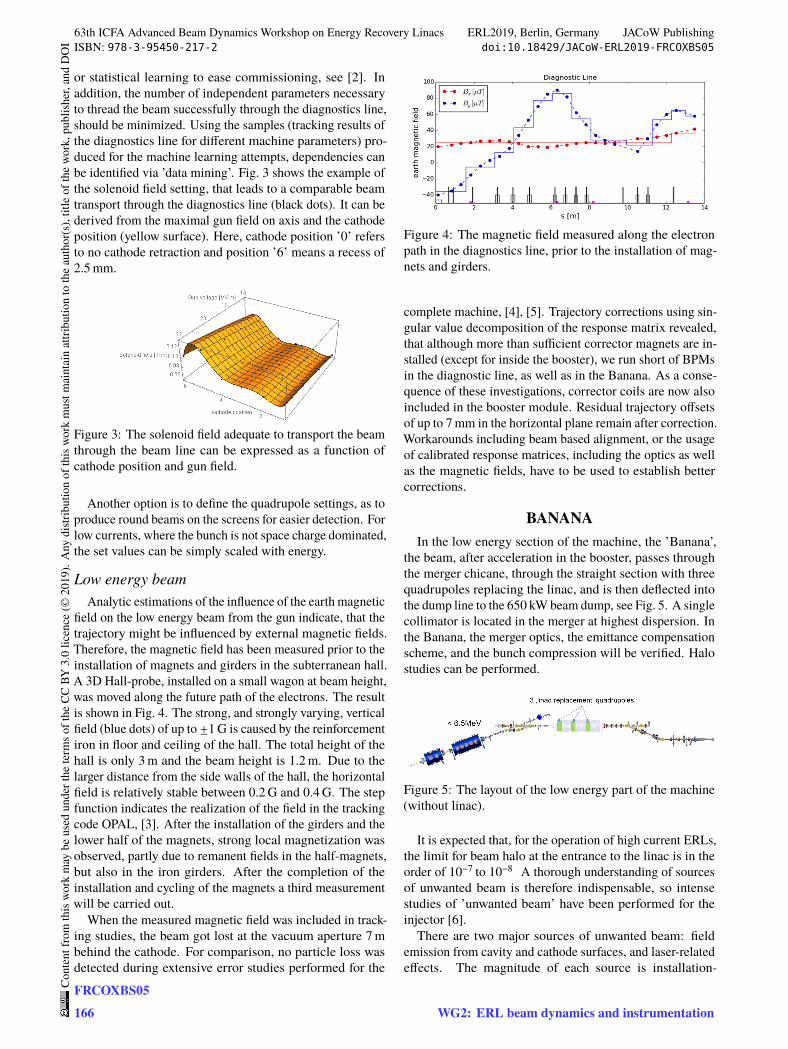
gle cavity SRF gun, providing up to 3 MeV electrons with adesign bunch charge of 77 pC. The gun module also hoststwo corrector coils (H/V) and a cold solenoid. The booster,hosting three two-cell cavities can boost the energy up to6.5 MeV. The first cavity imprints a chirp on the bunch for ve-locity bunching, while the other two cavities are run on crestfor acceleration. Further elements are 6 quadrupoles, a trans-verse deflecting cavity, a spectrometer followed by a 300 W
∗ Work supported by German Bundesministerium für Bildung undForschung, Land Berlin and grants of the Helmholtz Association
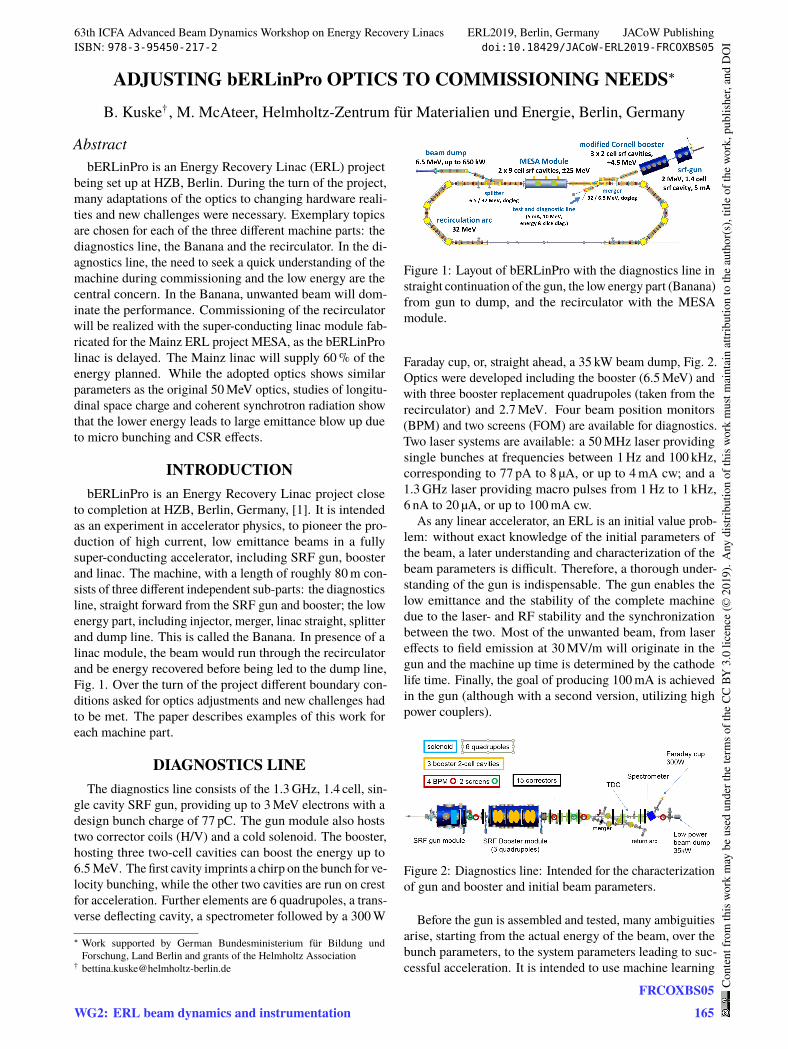
Figure 1: Layout of bERLinPro with the diagnostics line instraight continuation of the gun, the low energy part (Banana)from gun to dump, and the recirculator with the MESAmodule.
Faraday cup, or, straight ahead, a 35 kW beam dump, Fig. 2.Optics were developed including the booster (6.5 MeV) andwith three booster replacement quadrupoles (taken from therecirculator) and 2.7 MeV. Four beam position monitors(BPM) and two screens (FOM) are available for diagnostics.Two laser systems are available: a 50 MHz laser providingsingle bunches at frequencies between 1 Hz and 100 kHz,corresponding to 77 pA to 8 µA, or up to 4 mA cw; and a1.3 GHz laser providing macro pulses from 1 Hz to 1 kHz,6 nA to 20 µA, or up to 100 mA cw.
As any linear accelerator, an ERL is an initial value prob-lem: without exact knowledge of the initial parameters ofthe beam, a later understanding and characterization of thebeam parameters is difficult. Therefore, a thorough under-standing of the gun is indispensable. The gun enables thelow emittance and the stability of the complete machinedue to the laser- and RF stability and the synchronizationbetween the two. Most of the unwanted beam, from lasereffects to field emission at 30 MV/m will originate in thegun and the machine up time is determined by the cathodelife time. Finally, the goal of producing 100 mA is achievedin the gun (although with a second version, utilizing highpower couplers).
Figure 2: Diagnostics line: Intended for the characterizationof gun and booster and initial beam parameters.
Before the gun is assembled and tested, many ambiguitiesarise, starting from the actual energy of the beam, over thebunch parameters, to the system parameters leading to suc-cessful acceleration. It is intended to use machine learning
63th ICFA Advanced Beam Dynamics Workshop on Energy Recovery Linacs ERL2019, Berlin, Germany JACoW PublishingISBN: 978-3-95450-217-2 doi:10.18429/JACoW-ERL2019-FRCOXBS05
WG2: ERL beam dynamics and instrumentationFRCOXBS05
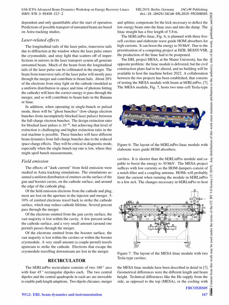
or statistical learning to ease commissioning, see [2]. Inaddition, the number of independent parameters necessaryto thread the beam successfully through the diagnostics line,should be minimized. Using the samples (tracking results ofthe diagnostics line for different machine parameters) pro-duced for the machine learning attempts, dependencies canbe identified via ’data mining’. Fig. 3 shows the example ofthe solenoid field setting, that leads to a comparable beamtransport through the diagnostics line (black dots). It can bederived from the maximal gun field on axis and the cathodeposition (yellow surface). Here, cathode position ’0’ refersto no cathode retraction and position ’6’ means a recess of2.5 mm.
Figure 3: The solenoid field adequate to transport the beamthrough the beam line can be expressed as a function ofcathode position and gun field.
Another option is to define the quadrupole settings, as toproduce round beams on the screens for easier detection. Forlow currents, where the bunch is not space charge dominated,the set values can be simply scaled with energy.
Low energy beamAnalytic estimations of the influence of the earth magnetic
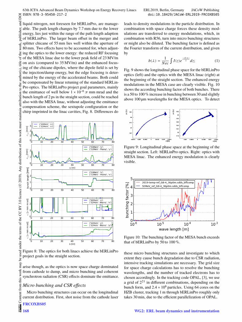
field on the low energy beam from the gun indicate, that thetrajectory might be influenced by external magnetic fields.Therefore, the magnetic field has been measured prior to theinstallation of magnets and girders in the subterranean hall.A 3D Hall-probe, installed on a small wagon at beam height,was moved along the future path of the electrons. The resultis shown in Fig. 4. The strong, and strongly varying, verticalfield (blue dots) of up to ±1 G is caused by the reinforcementiron in floor and ceiling of the hall. The total height of thehall is only 3 m and the beam height is 1.2 m. Due to thelarger distance from the side walls of the hall, the horizontalfield is relatively stable between 0.2 G and 0.4 G. The stepfunction indicates the realization of the field in the trackingcode OPAL, [3]. After the installation of the girders and thelower half of the magnets, strong local magnetization wasobserved, partly due to remanent fields in the half-magnets,but also in the iron girders. After the completion of theinstallation and cycling of the magnets a third measurementwill be carried out.
When the measured magnetic field was included in track-ing studies, the beam got lost at the vacuum aperture 7 mbehind the cathode. For comparison, no particle loss wasdetected during extensive error studies performed for the
Figure 4: The magnetic field measured along the electronpath in the diagnostics line, prior to the installation of mag-nets and girders.
complete machine, [4], [5]. Trajectory corrections using sin-gular value decomposition of the response matrix revealed,that although more than sufficient corrector magnets are in-stalled (except for inside the booster), we run short of BPMsin the diagnostic line, as well as in the Banana. As a conse-quence of these investigations, corrector coils are now alsoincluded in the booster module. Residual trajectory offsetsof up to 7 mm in the horizontal plane remain after correction.Workarounds including beam based alignment, or the usageof calibrated response matrices, including the optics as wellas the magnetic fields, have to be used to establish bettercorrections.
BANANAIn the low energy section of the machine, the ’Banana’,
the beam, after acceleration in the booster, passes throughthe merger chicane, through the straight section with threequadrupoles replacing the linac, and is then deflected intothe dump line to the 650 kW beam dump, see Fig. 5. A singlecollimator is located in the merger at highest dispersion. Inthe Banana, the merger optics, the emittance compensationscheme, and the bunch compression will be verified. Halostudies can be performed.
Figure 5: The layout of the low energy part of the machine(without linac).
It is expected that, for the operation of high current ERLs,the limit for beam halo at the entrance to the linac is in theorder of 10−7 to 10−8 A thorough understanding of sourcesof unwanted beam is therefore indispensable, so intensestudies of ’unwanted beam’ have been performed for theinjector [6].
There are two major sources of unwanted beam: fieldemission from cavity and cathode surfaces, and laser-relatedeffects. The magnitude of each source is installation-
63th ICFA Advanced Beam Dynamics Workshop on Energy Recovery Linacs ERL2019, Berlin, Germany JACoW PublishingISBN: 978-3-95450-217-2 doi:10.18429/JACoW-ERL2019-FRCOXBS05
dependent and only quantifiable after the start of operation.Predictions of possible transport of unwanted beam are basedon Astra tracking studies.
Laser-related effectsThe longitudinal tails of the laser pulse, transverse tails
due to diffraction at the window where the laser pulse entersthe cryomodule, and stray light that scatters off of imper-fections in mirrors in the laser transport system all generateunwanted beam. Much of the beam from the longitudinaltails of the laser pulse can be collimated in the merger. Thebeam from transverse tails of the laser pulse will mostly passthrough the merger and contribute to beam halo. About 20%of the electrons from stray light on the cathode (modeled asa uniform distribution in space and time of photons hittingthe cathode) will have the correct energy to pass through themerger, and so will contribute to beam halo in the Bananaor linac.
In addition, when operating in single-bunch or pulsedmode, there will be ”ghost bunches” (low-charge electronbunches from incompletely-blocked laser pulses) betweenthe full-charge electron bunches. The design extinction ratiofor blocked laser pulses is 10−8, but achieving that level ofextinction is challenging and higher extinction ratio in thereal machine is possible. These bunches will have differentbeam dynamics from full-charge bunches due to the reducedspace charge effects. They will be critical in diagnostic mode,especially when the single-bunch rep rate is low, where theymight spoil bunch measurements.
Field emissionThe effects of ”dark current” from field emission were
studied in Astra tracking simulations. The simulations as-sumed a uniform distribution of emitters on the surface of thegun and booster cavies, on the cathode surface, and aroundthe edge of the cathode plug.
Of the field emission electrons from the cathode and plug,most are lost on the aperture in the injector and merger. 5-10% of emitted electrons travel back to strike the cathodesurface, which may reduce cathode lifetime. Several percentpass through the merger.
Of the electrons emitted from the gun cavity surface, thevast majority is lost within the cavity. A few percent strikethe cathode surface, and a very small amount (around onepermil) passes through the merger.
Of the electrons emitted from the booster surface, thevast majority is lost within the cavities or within the boostercryomodule. A very small amount (a couple permil) travelsupstream to strike the cathode. Electrons that escape thecryomodule travelling downstream are lost in the merger.
RECIRCULATORThe bERLinPro recirculator consists of two 180 ° arcs
with four 45 ° rectangular dipoles each. The two centraldipoles and the central quadrupole in each arc are moveableto enable path length adaptions. Two dipole chicanes, merger
and splitter, compensate for the kick necessary to deflect thelow energy beam onto the linac axes and into the dump. Thelinac straight has a free length of 5.8 m.
The bERLinPro linac, Fig. 6, is planned with three five-cell cavities and elaborate wave guide HOM absorbers forhigh currents. It can boost the energy to 50 MeV. Due to theprioritization of a competing project at HZB, BESSY-VSR,the production of the linac had to be postponed.
The ERL project MESA, at the Mainz University, has theopposite problem: the linac module is delivered, but the civilconstruction plans had to be altered, and no building will beavailable to host the machine before 2022. A collaborationbetween the two projects has been established, that consistsof testing the MESA module with beam at bERLinPro, [7].The MESA module, Fig. 7, hosts two nine-cell Tesla-type
Figure 6: The layout of the bERLinPro linac module withelaborate wave guide HOM absorbers.
cavities. It is shorter than the bERLinPro module and ca-pable to boost the energy to 30 MeV. The MESA projectsuffices with low currents so the HOM dampers consist ofa notch-filter and a coupling antenna. HOMs will probablylimit the current when running the module in bERLinProto a few mA. The changes necessary in bERLinPro to host
Figure 7: The layout of the MESA linac module with twoTesla-type cavities.
the MESA linac module have been described in detail in [7].Geometrical differences were the different length and beamheight. Technical differences like the He-supply from theside, as opposed to the top (MESA), or the cooling with
63th ICFA Advanced Beam Dynamics Workshop on Energy Recovery Linacs ERL2019, Berlin, Germany JACoW PublishingISBN: 978-3-95450-217-2 doi:10.18429/JACoW-ERL2019-FRCOXBS05
WG2: ERL beam dynamics and instrumentationFRCOXBS05
liquid nitrogen, not foreseen for bERLinPro, are manage-able. The path length changes by 7.7 mm due to the lowerenergy, lies just within the range of the path length adaptionof bERLinPro. The larger beam offset in the merger andsplitter chicane of 55 mm lies well within the aperture of80 mm. Two effects have to be accounted for, when adjust-ing the optics to the lower energy: the reduced RF focusingof the MESA linac due to the lower peak field of 23 MV/mon axis (compared to 35 MV/m) and the enhanced focus-ing of the chicane dipoles, where the dipole field is set bythe injection/dump energy, but the edge focusing is deter-mined by the energy of the accelerated beams. Both couldbe compensated by linear retuning of the standard bERLin-Pro optics. The bERLinPro project goal parameters, mainlythe emittance of well below 1 × 10⁻⁶ 𝜋 mm mrad and thebunch length of 2 ps in the straight section, could be reachedalso with the MESA linac, without adjusting the emittancecompensation scheme, the sextupole configuration or thechirp imprinted in the linac cavities, Fig. 8. Differences do
Figure 8: The optics for both linacs achieve the bERLinProproject goals in the straight section.
arise though, as the optics is now space charge dominatedfrom cathode to dump, and micro bunching and coherentsynchrotron radiation (CSR) effects dominate the emittance.
Micro bunching and CSR effectsMicro bunching structures can occur on the longitudinal
current distribution. First, shot noise from the cathode laser
leads to density modulations in the particle distribution. Incombination with space charge forces these density mod-ulations are transferred to energy modulations, which, incombination with R56, turn into micro bunching structuresor might also be diluted. The bunching factor is defined asthe Fourier transform of the current distribution, and givenby
𝑏(𝜆) = 1𝑁𝑒𝑐 ∫ 𝐼(𝑧)𝑒
−𝑖2𝜋𝑧𝜆 𝑑𝑧; (1)
Fig. 9 shows the longitudinal phase space for the bERLinProoptics (left) and the optics with the MESA linac (right) atthe beginning of the straight section. The enhanced energymodulations in the MESA case are clearly visible. Fig. 10shows the according bunching factor of both bunches. Thereis a 50 to 100 % increase in bunching between 30 and slightlyabove 100 µm wavelengths for the MESA optics. To detect
Figure 9: Longitudinal phase space at the beginning of thestraight section. Left: bERLinPro optics. Right: optics withMESA linac. The enhanced energy modulation is clearlyvisible.
Figure 10: The bunching factor of the MESA bunch exceedsthat of bERLinPro by 50 to 100 %.
these micro bunching structures and investigate to whichextent they cause bunch degradation due to CSR radiation,intensive tracking simulations are necessary. The grid sizefor space charge calculations has to resolve the bunchingwavelengths, and the number of tracked electrons has tochosen accordingly. In the tracking code OPAL, [3], we usea grid of 221 in different combinations, depending on thebunch form, and 2.4 × 10⁶ particles. Using 64 cores on theHZB cluster, tracking 1 m through bERLinPro roughly onlytakes 30 min, due to the efficient parallelization of OPAL.
63th ICFA Advanced Beam Dynamics Workshop on Energy Recovery Linacs ERL2019, Berlin, Germany JACoW PublishingISBN: 978-3-95450-217-2 doi:10.18429/JACoW-ERL2019-FRCOXBS05
No enhancement of micro bunching due to CSR radiationcould be observed in either case. But CSR effects do cause aloss of energy of 10 keV in both cases. They also deterioratethe emittance in both cases, although much stronger for theoptics with the MESA linac. It should be noticed, that due tothe enhanced grid size and the vast amount of particles,the emittance already increases by 15 % for both optics,compared to the standard grid of 32³ and 105 particles. Theincrease due to space charge, and due to the combination ofspace charge and CSR is listed in Table 1. The emittance
Table 1: Increase of the Horizontal Emittance after First Arc
blow up due to space charge exceeds that due to CSR byalmost a factor of three. While for the bERLinPro case theemittance values stay within the project goals, at reducedenergy, the horizontal emittance is doubled. This could notbe seen in the standard tracking calculations with a decentnumber of grid cells and particles.
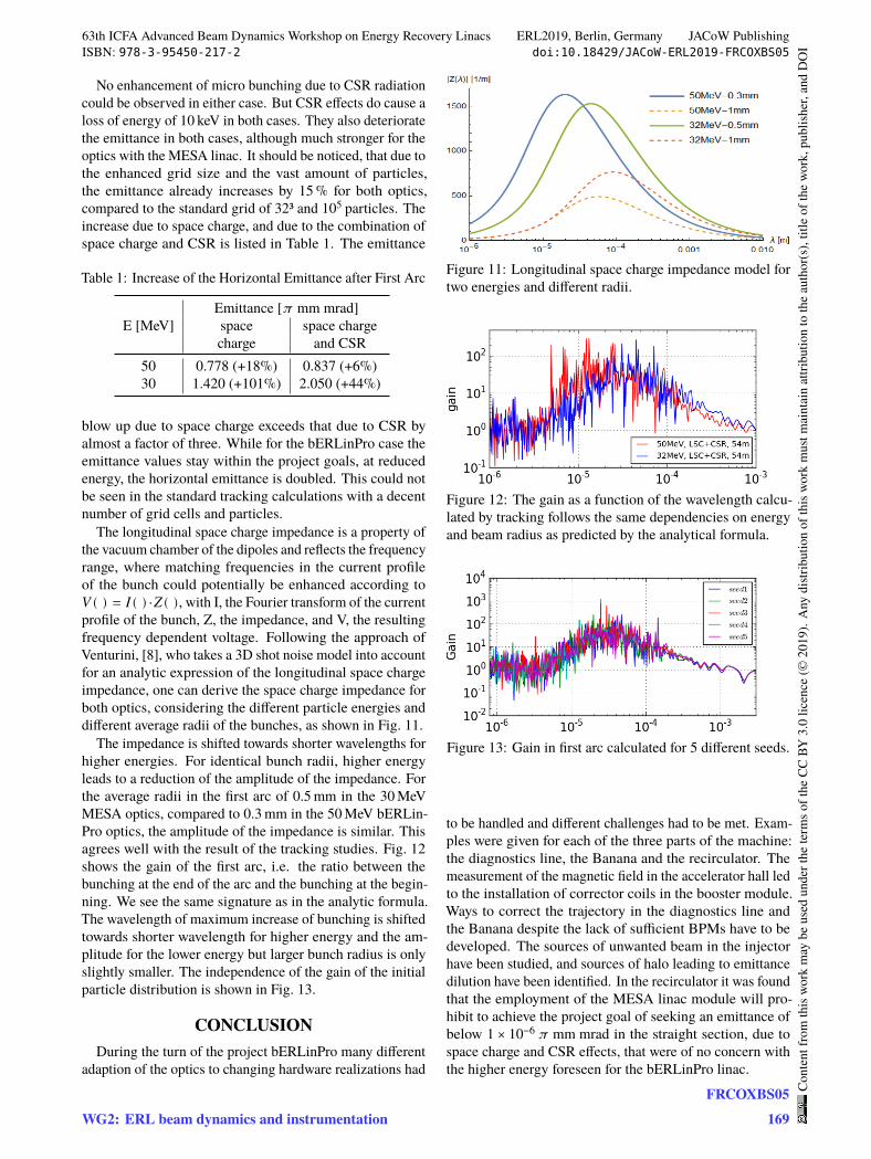
The longitudinal space charge impedance is a property ofthe vacuum chamber of the dipoles and reflects the frequencyrange, where matching frequencies in the current profileof the bunch could potentially be enhanced according to𝑉(�) = 𝐼(�)⋅𝑍(�), with I, the Fourier transform of the currentprofile of the bunch, Z, the impedance, and V, the resultingfrequency dependent voltage. Following the approach ofVenturini, [8], who takes a 3D shot noise model into accountfor an analytic expression of the longitudinal space chargeimpedance, one can derive the space charge impedance forboth optics, considering the different particle energies anddifferent average radii of the bunches, as shown in Fig. 11.
The impedance is shifted towards shorter wavelengths forhigher energies. For identical bunch radii, higher energyleads to a reduction of the amplitude of the impedance. Forthe average radii in the first arc of 0.5 mm in the 30 MeVMESA optics, compared to 0.3 mm in the 50 MeV bERLin-Pro optics, the amplitude of the impedance is similar. Thisagrees well with the result of the tracking studies. Fig. 12shows the gain of the first arc, i.e. the ratio between thebunching at the end of the arc and the bunching at the begin-ning. We see the same signature as in the analytic formula.The wavelength of maximum increase of bunching is shiftedtowards shorter wavelength for higher energy and the am-plitude for the lower energy but larger bunch radius is onlyslightly smaller. The independence of the gain of the initialparticle distribution is shown in Fig. 13.
CONCLUSIONDuring the turn of the project bERLinPro many different
adaption of the optics to changing hardware realizations had
Figure 11: Longitudinal space charge impedance model fortwo energies and different radii.
Figure 12: The gain as a function of the wavelength calcu-lated by tracking follows the same dependencies on energyand beam radius as predicted by the analytical formula.
Figure 13: Gain in first arc calculated for 5 different seeds.
to be handled and different challenges had to be met. Exam-ples were given for each of the three parts of the machine:the diagnostics line, the Banana and the recirculator. Themeasurement of the magnetic field in the accelerator hall ledto the installation of corrector coils in the booster module.Ways to correct the trajectory in the diagnostics line andthe Banana despite the lack of sufficient BPMs have to bedeveloped. The sources of unwanted beam in the injectorhave been studied, and sources of halo leading to emittancedilution have been identified. In the recirculator it was foundthat the employment of the MESA linac module will pro-hibit to achieve the project goal of seeking an emittance ofbelow 1 × 10⁻⁶ 𝜋 mm mrad in the straight section, due tospace charge and CSR effects, that were of no concern withthe higher energy foreseen for the bERLinPro linac.
63th ICFA Advanced Beam Dynamics Workshop on Energy Recovery Linacs ERL2019, Berlin, Germany JACoW PublishingISBN: 978-3-95450-217-2 doi:10.18429/JACoW-ERL2019-FRCOXBS05
WG2: ERL beam dynamics and instrumentationFRCOXBS05
REFERENCES[1] M. Abo-Bakr et al., “The Berlin Energy Recovery Linac
Project bERLinPro – Status, Plans and Future Opportuni-ties”, presented at ERL’19, Berlin, Germany, Sep. 2019, paper:MOCOXBS04, this conference.
[2] B. Kuske, A. Adelmann, “Commissioning of the bERLin-Pro Diagnostics Line using Machine Learning Techniques”,presented at ERL’19, Berlin, Germany, Sep. 2019, paper:WECOYBS05, this conference.
[4] B. Kuske, J. Rudolph, “Beam Positioning Concept andTolerance Considerations for bERLinPro”, TUPRO038, inProc. IPAC’14,Dresden, Germany, 2014. doi:10.18429/JACoW-IPAC2014-TUPRO038
[5] B. Kuske, Ch. Metzger-Kraus, “Start-to-end Cal-culations and Trajectory Correction for bERLin-
Pro”, in Proc. IPAC’16,Busan, Korea,2016. doi:10.18429/JACoW-IPAC2016-THOBA03.
[6] M. McAteer, “Dark current and halo tracking in ERLs”, pre-sented at ERL’17, Geneva, Switzerland, Jun 2017, paper THI-ACC002, unpublished.
[7] W. Anders, K. Aulenbacher, F. Hug, A. Jankowiak, B. Kuske,A. Neumann, T. Stengler, C.P. Stoll, “Incorporation of aMESA Linac Modules into bERLinPro”,in Proc. IPAC’19,Melbourne, Australia, May 2019, pp. 1449–1452, doi:10.18429/JACoW-IPAC2019-TUPGW023
[8] M. Venturini, “Models of longitudinal space - chargeimpedance for microbunching instability”, Phys. Rev. STAccel. Beams, vol. 11, p. 034401 (2008). doi=10.1103/PhysRevSTAB.11.034401
63th ICFA Advanced Beam Dynamics Workshop on Energy Recovery Linacs ERL2019, Berlin, Germany JACoW PublishingISBN: 978-3-95450-217-2 doi:10.18429/JACoW-ERL2019-FRCOXBS05