53
ME 010 701 Design of Machine Elements 2014 Lecture Notes ME010 701 Design of Machine Elements 1

ME 010 701 Design of Machine Elements 2014
Lecture Notes
ME010 701 Design of Machine Elements
1

ME 010 701 Design of Machine Elements 2014
SYLLABUS
Module I (15 Hrs)
System design cycle - Different phases in design process - design factors and considerations -
tolerances and fits - Hole basis & Shaft basis system - standardization - selection of materials -
stress concentration - Methods to reduce stress concentration - theoretical stress concentration
factor - theories of failure - Guest’s theory - Rankine’s theory - St. Venant’s theory - Haigh’s
theory - Von Mises & Hencky theory - shock and impact loads - fatigue loading - endurance
limit stress- Factors affecting endurance limit - Factor of safety - creep and thermal stresses.
Module II (15 Hrs)
Design of riveted joints- Failure of riveted joints and efficiency of joint -boiler and tank joints
structural joints, Cotter and Knuckle joints Threaded joints - thread standards- thread
nomenclature - stresses in screw threads- bolted joints preloading of bolts- eccentric loading-
fatigue loading of bolts - Power screws.
Module III (15 Hrs)
Design of welded joints- Representation of welds - stresses in fillet and butt welds- design for
static loads - bending and torsion in welded joints- eccentrically loaded welds - design of welds
for variable loads. Springs- stresses and deflection of helical springs with axial loading -
curvature effect - resilience - design of spring for static and fatigue loading- surging- critical
frequency- stress analysis and design of leaf springs..
Module IV (15 Hrs)
Shafts and axles design- stresses- causes of failure in shafts - design based on strength, rigidity
and critical speed- design for static and fatigue loads- repeated loading- reversed bending-
Design of couplings - Rigid and flexible couplings - design of keys and pins.
2
ME 010 701 Design of Machine Elements 2014
Module 1
Module I (15 Hrs)
System design cycle - Different phases in design process - design factors and considerations -
tolerances and fits - Hole basis & Shaft basis system - standardization - selection of materials -
stress concentration - Methods to reduce stress concentration - theoretical stress concentration
factor - theories of failure - Guest’s theory - Rankine’s theory - St. Venant’s theory - Haigh’s
theory - Von Mises & Hencky theory - shock and impact loads - fatigue loading - endurance limit
stress- Factors affecting endurance limit - Factor of safety - creep and thermal stresses.
Introduction
Design is essentially a decision-making process. If we have a problem, we need to design a
solution. In other words, to design is to formulate a plan to satisfy a particular need and to create
something with a physical reality.
The subject Machine Design is the creation of new and better machines and improving the
existing ones. A new or better machine is one which is more economical in the overall cost of
production and operation. From the study of existing ideas, a new idea has to be conceived. The
idea is then studied keeping in mind its commercial success and given shape and form in the
form of drawings. In designing a machine component, it is necessary to have a good knowledge
of many subjects such as Mathematics, Engineering Mechanics, Strength of Materials, Theory of
machines, Workshop Processes and Engineering Drawing.
System design cycleWhenever the new product or the machine is to be design there is a cycle of the steps that are
followed. The sequence of the events in the machine design or system design have been codified
Asimow, who is considered to be the father of system design or machine design. This sequence
of steps is called as system design cycle or machine design cycle. For solving any problem
related to engineering design and machine design or mechanical design the general procedure of
laid out by it can be followed.
3
ME 010 701 Design of Machine Elements 2014
Here are the steps of the sequence of system design cycle or machine design cycle:
1) Recognition of a need
2) Specifications and requirements
3) Feasibility study
4) Creative design synthesis
5) Preliminary design and development
6) Detailed design
7) Prototype building and testing
8) Design for production
4

ME 010 701 Design of Machine Elements 2014
9) Product release
Let us understand all these steps one-by-one in details. They have been shown in the figure for
clearer understanding of the individual steps and loops in the cycle. The first and most important
step of the system design or machine design is recognition of need.
1) Recognition of Need
Recognition of a need is the first and the most important step of the machine design or
system design cycle (see fig below), without this first step no further steps of the machine
design can be taken. It is the need that gives birth to various other steps of the design. If there
is no need there won’t be any reasons to start the detailed, time consuming and highly
complex problem of designing.
2) Specifications and Requirements
Stating the specifications and the requirements is the next important step of the system design
cycle or machine design cycle (see fig. below). In this step all the requirements and the
specifications of the need are studied in full details. Say for instance the new engine is to be
designed. Here the all the important requirements and specifications like the power engine
has to generate, the torque it has to produce, the speeds, the number of cylinders, type of fuel
to be used, the method of ignition etc, all such requirements and specifications have to be
considered.
3) Feasibility Study
The next important step of the system design or machine design cycle is feasibility study (see
fig below). Once the need or the problem has been identified and the specification have been
prepared, accepted and submitted for the approval, feasibility study is to be carried on the
proposal. The main purpose of the feasibility study is to check the possibility of the success
or failure of the proposed project both from technical as well as economic point of view.
Say for instance the specifications have been received by the company from military to
manufacture the truck. The company studies the specifications to find out if it is really
possible to manufacture this truck considering the technical aspects as well as the economic
aspects. If even one of these aspects fail to meet with the company’s expectations the whole
project will be abandoned. Thus the feasibility study will help to decide whether to move
5

ME 010 701 Design of Machine Elements 2014
ahead with the complex and time consuming design procedure or not. The feasibility study
helps avoid taking the fruitless steps if the project is not feasible technically or economically.
4) Creative Design Synthesis
The creative design synthesis is the first step of the actual design of the machine or product
and the most challenging and interesting part. With all the specifications in his/her hand the
designer has the most important task of creating the product as per the specifications and
requirements given by the host or the client company. Here the designer has to perform the
multiple roles of the engineer, the inventor and the artist so as to lay the foundation of the
creation of actual product.
5) Preliminary Design and Development
The next important step of the system design cycle or machine design cycle is making the
preliminary design and the development of the product (see the fig below). Remember this is
just the preliminary design and not the final design. After using his/her creativity the designer
designs one or more designs for the product or machine fulfilling all the given set of the
specifications and requirements for the product. From the multiple solutions available for the
product, the one with the best solution will be selected for the important stage of the
preliminary design and development. The basis for selecting the best design as the
preliminary design for development can be varied.
6) Detailed Design
After doing the preliminary design and development of the machine the next important step
is making the detailed design of the machine or product (see the fig below). This stage of the
machine design cycle should not be confused or mixed with the previous stage of making the
preliminary design. Many designers think that all the designing that has been done in the
preliminary stage is quite sufficient, but this is a wrong notion. At the preliminary design
stage certain changes can be made in the design, but once it has been finalized no further
changes can be made. The details of the finalized design are worked out in the detailed
design stage of the machine design cycle.
7) Prototype Building and Testing
In the previous step of the detailed design all the details of the product or the machine were
worked out. In the next stage of prototype building and testing (see fig below) all the details,
6
ME 010 701 Design of Machine Elements 2014
the subassemblies, and assembly drawings including the materials and part list, the
completed design is sent to the prototype or the model shop for fabrication. The prototype is
the model of the machine developed as per the detailed design.
8) Design for Production
Once the prototype testing is successful all the drawings, parts and material lists are sent to
the production engineering department where the drawings are modified are so that the
design for production is made for the completed project (see fig below). During the design
for production stage the consideration is given to the design changes to so as to make it
compatible with the most economical methods of production.
During design for production the manufacturing methods that will help manufacturing the
product in most economic way and in the shortest possible time are considered. Every
product requires multiple components and multiple phases of production. During the design
for production the shortest possible manufacturing cycle for the product is found.
9) Product Release
After making the complete drawings and production planning the drawings are sent the shop
floor for product release and actual manufacturing of the product (see fig below). Even here
the mass production is not done immediately; rather some prototypes are made and tested. If
any drawbacks are found in the final these, these are sent back for the feedback to the
preliminary or detailed design stage for making the necessary changes (see fig). Once the
product is found satisfactory its mass production is carried out as per the production
planning.
7
ME 010 701 Design of Machine Elements 2014
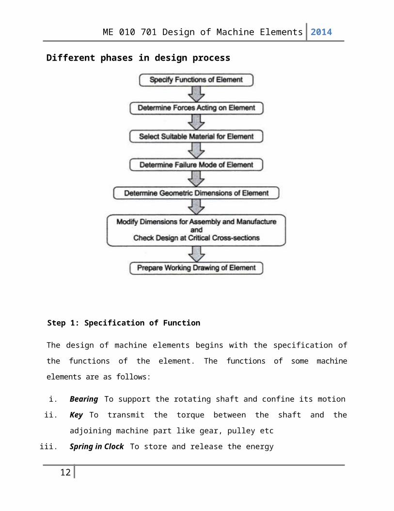
Different phases in design process
Step 1: Specification of Function
The design of machine elements begins with the specification of the functions of the element. The
functions of some machine elements are as follows:
i. Bearing To support the rotating shaft and confine its motion
ii. Key To transmit the torque between the shaft and the adjoining machine part like gear,
pulley etc
iii. Spring in Clock To store and release the energy
iv. Spring in Spring Balance To measure the force
v. Screw Fastening To hold two or more machine parts together
vi. Power Screw To produce uniform and slow motion and to transmit the force
8
ME 010 701 Design of Machine Elements 2014
Step 2: Determination of Forces
In many cases, a free-body diagram of forces is constructed to determine the forces acting on
different parts of the machine. The external and internal forces that act on a machine element are as
follows:
i. The external force due to energy, power or torque transmitted by the machine part, often
called 'useful' load
ii. Static force due to deadweight of the machine part
iii. Force due to frictional resistance
iv. Inertia force due to change in linear or angular velocity
v. Centrifugal force due to change in direction of velocity
vi. Force due to thermal gradient or variation in temperature
vii. Force set up during manufacturing the part resulting in residual stresses
viii. Force due to particular shape of the part such as stress concentration due to abrupt change in
cross-section
For every machine element, all forces in this list may not be applicable. They vary depending on
the application. There is one more important consideration. The force acting on the machine part
is either assumed to be concentrated at some point in the machine part or distributed over a
particular area. Experience is essential to make such assumptions in the analysis of forces.
Step 3: Selection of Material
Four basic factors, which are considered in selecting the material, are availability, cost, mechanical
properties and manufacturing considerations.
For example, flywheel, housing of gearbox or engine block have complex shapes. These
components are made of cast iron because the casting process produces complicated shapes without
involving machining operations. Transmission shafts are made of plain carbon steels, because they are
available in the form of rods, besides their higher strength.
Step 4: Failure Criterion
Before finding out the dimensions of the component, it is necessary to know the type of failure that the
component may fail when put into service. The machine component is said to have 'failed’ when it is
unable to perform its functions satisfactorily. The three basic types of failure are as follows:
9
ME 010 701 Design of Machine Elements 2014
i. failure by elastic deflection;
ii. failure by general yielding; and
iii. failure by fracture.
For example, In applications like transmission shaft, which is used to support gears, the
maximum force acting on the shaft is limited by the permissible deflection. When this deflection
exceeds a particular value (usually, 0.001 to 0.003 times of span length between two bearings), the
meshing between teeth of gears is affected and the shaft cannot perform its function properly, in this
case, the shaft is said to have 'failed’ due to elastic deflection.
Step 5: Determination of Dimensions
The shape of the machine element depends on two factors, viz., the operating conditions and the shape of
the adjoining machine element. For example, involute profile is used for gear teeth because it
satisfies the fundamental law of gearing. A V-belt has a trapezoidal cross-section because it results
in wedge action and increases the force of friction between the surfaces of the belt and the pulley. On the
other hand, the pulley of a V-belt should have a shape which will match with the adjoining belt. The
profile of the teeth of sprocket wheel should match the roller, bushing, inner and outer link plates of the
roller chain. Depending on the operating conditions and shape of the adjoining element, the shape of
the machine element is decided and a rough sketch is prepared. The geometric dimensions of the
component are determined on the basis of failure criterion. In simple cases, the dimensions are
determined on the basis of allowable stress or deflection.
Step 6: Design Modifications
The geometric dimensions of the machine element are modified from assembly and manufacturing
considerations. For example, the transmission shaft illustrated in Fig. 1.4 is provided with steps and
shoulders for proper mounting of gear and bearings. Revised calculations are carried out for operating
capacity, margin of safety at critical cross-sections and resultant stresses taking into consideration die
effect of stress concentration. When these values differ from desired values, the dimensions of the
component arc modified. The process is continued till the desired values of operating capacity, factor of
safety and stresses at critical cross-sections are obtained.
Step 7: Working Drawing
10
ME 010 701 Design of Machine Elements 2014
The last step in the design of machine elements is to prepare a working drawing of the machine
element showing dimensions, tolerances, surface finish grades, geometric tolerances and special
production requirements like heat treatment. The working drawing must be clear, concise and
complete. It must have enough views and cross-sections to show all details. The main view of the
machine element should show it in a position, it is required to occupy in service. Every
dimension must be given. There should not be scope for guesswork and a necessity for scaling
the drawing. All dimensions that are important for proper assembly and interchangeability must
be provided with tolerances.
Design factors and considerationsFollowing are the general considerations in designing a machine component:
1) Type of load and stresses caused by the load. The load, on a machine component, may act in
several ways due to which the internal stresses are set up. The various types of load and
stresses are discussed later.
2) Motion of the parts or kinematics of the machine. The successful operation of any machine
depends largely upon the simplest arrangement of the parts which will give the motion
required.
The motion of the parts may be:
(a) Rectilinear motion which includes unidirectional and reciprocating motions.
(b) Curvilinear motion which includes rotary, oscillatory and simple harmonic.
(c) Constant velocity.
(d) Constant or variable acceleration.
3) Selection of materials. It is essential that a designer should have a thorough knowledge of
the properties of the materials and their behaviour under working conditions. Some of the
important characteristics of materials are: strength, durability, flexibility, weight, resistance
to heat and corrosion, ability to cast, welded or hardened, machinability, electrical
conductivity, etc. The various types of engineering materials and their properties are
discussed later.
4) Form and size of the parts. The form and size are based on judgment. The smallest
practicable cross-section may be used, but it may be checked that the stresses induced in the
designed cross-section are reasonably safe. In order to design any machine part for form and
11
ME 010 701 Design of Machine Elements 2014
size, it is necessary to know the forces which the part must sustain. It is also important to
anticipate any suddenly applied or impact load which may cause failure.
5) Frictional resistance and lubrication. There is always a loss of power due to frictional
resistance and it should be noted that the friction of starting is higher than that of running
friction. It is, therefore, essential that a careful attention must be given to the matter of
lubrication of all surfaces which move in contact with others, whether in rotating, sliding, or
rolling bearings.
6) Convenient and economical features. In designing, the operating features of the machine
should be carefully studied. The starting, controlling and stopping levers should be located
on the basis of convenient handling. The adjustment for wear must be provided employing
the various take up devices and arranging them so that the alignment of parts is preserved. If
parts are to be changed for different products or replaced on account of wear or breakage,
easy access should be provided and the necessity of removing other parts to accomplish this
should be avoided if possible. The economical operation of a machine which is to be used for
production or for the processing of material should be studied, in order to learn whether it has
the maximum capacity consistent with the production of good work.
7) Use of standard parts. The use of standard parts is closely related to cost, because the cost of
standard or stock parts is only a fraction of the cost of similar parts made to order. The
standard or stock parts should be used whenever possible; parts for which patterns are
already in existence such as gears, pulleys and bearings and parts which may be selected
from regular shop stock such as screws, nuts and pins. Bolts and studs should be as few as
possible to avoid the delay caused by changing drills, reamers and taps and also to decrease
the number of wrenches required.
8) Safety of operation. Some machines are dangerous to operate, especially those which are
speeded up to insure production at a maximum rate. Therefore, any moving part of a machine
which is within the zone of a worker is considered an accident hazard and may be the cause
of an injury. It is, therefore, necessary that a designer should always provide safety devices
for the safety of the operator. The safety appliances should in no way interfere with operation
of the machine.
9) Workshop facilities. A design engineer should be familiar with the limitations of this
employer’s workshop, in order to avoid the necessity of having work done in some other
12

ME 010 701 Design of Machine Elements 2014
workshop. It is sometimes necessary to plan and supervise the workshop operations and to
draft methods for casting, handling and machining special parts.
10) Number of machines to be manufactured. The number of articles or machines to be
manufactured affects the design in a number of ways. The engineering and shop costs which
are called fixed charges or overhead expenses are distributed over the number of articles to
be manufactured. If only a few articles are to be made, extra expenses are not justified unless
the machine is large or of some special design. An order calling for small number of the
product will not permit any undue expense in the workshop processes, so that the designer
should restrict his specification to standard parts as much as possible.
11) Cost of construction. The cost of construction of an article is the most important
consideration involved in design. In some cases, it is quite possible that the high cost of an
article may immediately bar it from further considerations. If an article has been invented and
tests of handmade samples have shown that it has commercial value, it is then possible to
justify the expenditure of a considerable sum of money in the design and development of
automatic machines to produce the article, especially if it can be sold in large numbers. The
aim of design engineer under all conditions should be to reduce the manufacturing cost to the
minimum.
12) Assembling. Every machine or structure must be assembled as a unit before it can function.
Large units must often be assembled in the shop, tested and then taken to be transported to
their place of service. The final location of any machine is important and the design engineer
must anticipate the exact location and the local facilities for erection.
Tolerances and FitsThe term interchangeability is normally employed for the mass production of identical items
within the prescribed limits of sizes. A little consideration will show that in order to maintain the
sizes of the part within a close degree of accuracy, a lot of time is required. But even then there
will be small variations. If the variations are within certain limits, all parts of equivalent size will
be equally fit for operating in machines and mechanisms. Therefore, certain variations are
recognized and allowed in the sizes of the mating parts to give the required fitting. This
facilitates to select at random from a large number of parts for an assembly and results in a
considerable saving in the cost of production.
13
ME 010 701 Design of Machine Elements 2014
In order to control the size of finished part, with due allowance for error, for interchangeable
parts is called limit system It may be noted that when an assembly is made of two parts, the part
which enters into the other, is known as enveloped surface (or shaft for cylindrical part) and the
other in which one enters is called enveloping surface (or hole for cylindrical part). The term
shaft refers not only to the diameter of a circular shaft, but it is also used to designate any
external dimension of a part. The term hole refers not only to the diameter of a circular hole, but
it is also used to designate any internal dimension of a part.
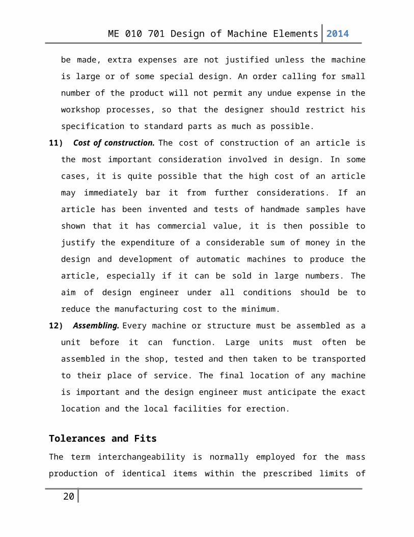
Interrelationship between tolerances and limits
Tolerance
Tolerance is the difference between maximum and minimum dimensions of a component, ie,
between upper limit and lower limit. Depending on the type of application, the permissible
variation of dimension is set as per available standard
grades.
Tolerance is of two types, bilateral and unilateral.
When tolerance is present on both sides of nominal
size, it is termed as bilateral; unilateral has tolerance
only on one side. The Figure shows the types of
tolerance. 50-y0, 500
+x and 50-y+x is a typical example
14

ME 010 701 Design of Machine Elements 2014
of specifying tolerance for a shaft of nominal
diameter of 50mm. First two values denote
unilateral tolerance and the third value denotes
bilateral tolerance. Values of the tolerance are given
as x and y respectively.
Allowance
It is the difference of dimension between two mating parts.
Upper deviation
It is the difference of dimension between the maximum possible size of the component and its
nominal size.
Lower deviation
Similarly, it is the difference of dimension between the minimum possible size of the component
and its nominal size.
Fundamental deviation
It defines the location of the tolerance zone with respect to the nominal size. For that matter,
either of the deviations may be considered.
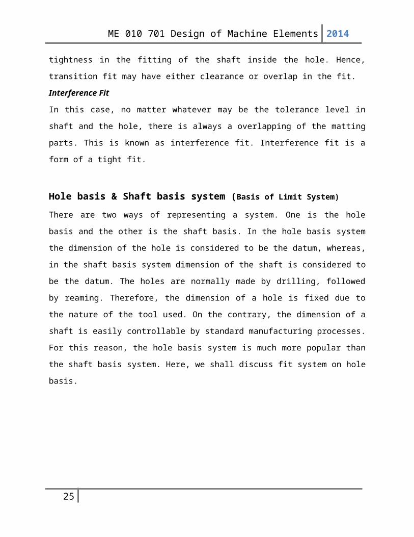
Fit SystemWe have learnt above that a machine part when manufactured has a specified tolerance.
Therefore, when two mating parts fit with each other, the nature of fit is dependent on the limits
of tolerances and fundamental deviations of the mating parts. The nature of assembly of two
mating parts is defined by three types of fit system, Clearance Fit, Transition Fit and Interference
Fit. The fit system is shown schematically in Figure below
Clearance Fit
In this type of fit, the shaft of largest possible diameter can also be fitted easily even in the hole
of smallest possible diameter.
15
ME 010 701 Design of Machine Elements 2014
Transition Fit
In this case, there will be a clearance between the minimum dimension of the shaft and the
minimum dimension of the hole. If we look at the figure carefully, then it is observed that if the
shaft dimension is maximum and the hole dimension is minimum then an overlap will result and
this creates a certain amount of tightness in the fitting of the shaft inside the hole. Hence,
transition fit may have either clearance or overlap in the fit.
Interference Fit
In this case, no matter whatever may be the tolerance level in shaft and the hole, there is always a
overlapping of the matting parts. This is known as interference fit. Interference fit is a form of a
tight fit.
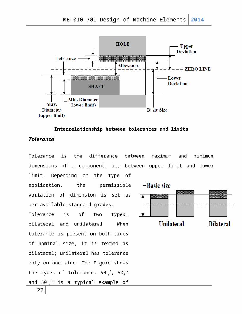
Hole basis & Shaft basis system (Basis of Limit System)There are two ways of representing a system. One is the hole basis and the other is the shaft
basis. In the hole basis system the dimension of the hole is considered to be the datum, whereas,
in the shaft basis system dimension of the shaft is considered to be the datum. The holes are
16
ME 010 701 Design of Machine Elements 2014
normally made by drilling, followed by reaming. Therefore, the dimension of a hole is fixed due
to the nature of the tool used. On the contrary, the dimension of a shaft is easily controllable by
standard manufacturing processes. For this reason, the hole basis system is much more popular
than the shaft basis system. Here, we shall discuss fit system on hole basis.
Problem-1:The dimensions of the mating parts, according to basic hole system, are given asHole : 25.00 mm Shaft : 24.97 mm
25.02 mm 24.95 mmFind the hole tolerance, shaft tolerance and allowance.
17

ME 010 701 Design of Machine Elements 2014
StandardizationStandardization is defined as obligatory norms, to which various characteristics of a product
should conform. The characteristics include materials, dimensions and shape of the component,
method of testing and method of marking, packing and storing of the product. The following
standards are used in mechanical engineering design:
1) Standards for Materials, their Chemical Compositions, Mechanical Properties and
Heat Treatment For example, Indian standard IS 210 specifies seven grades of grey cast
iron designated as FG 150, FG 200, FG 220, FG 260, FG 300, FG 350 and FG 400. The
number indicates ultimate tensile strength in N/mm2. IS 1570 (Part 4) specifies chemical
composition of various grades of alloy steel. For example, alloy steel designated by 55Cr3
has 0.5-0.6% carbon, 0.10-0.35% silicon, 0.6-0.8% manganese and 0.6-0.8% chromium.
2) Standards for Shapes and Dimensions of Commonly used Machine Elements The
machine elements include bolts, screws and nuts, rivets, belts and chains, ball and roller
bearings, wire ropes, keys and splines, etc. For example, IS 2494 (Part 1) specifies
dimensions and shape of the cross-section of endless V-bclts for power transmission. The
dimensions of the trapezoidal cross-section of the belt, viz. width, height and included angle
are specified in this standard. The dimensions of rotary shaft oil seal units are given in IS
5129 (Part I). These dimensions include inner and outer diameters and width of oil seal units.
3) Standards for Fits, Tolerances and Surface Finish of Component For example, selection
of the type of fit for different applications is illustrated in IS 2709 on 'Guide for selection of
fits'. The tolerances or upper and tower limits for various sizes of holes and shafts arc
specified in IS 919 on 'Recommendations for limits and fits for engineering'. IS 10719
explains method for indicating surface texture on technical drawings. The method of showing
geometrical tolerances is explained in IS 8000 on 'Geometrical tolerancingon technical
drawings'.
4) Standards for Testing of Products These standards, sometimes called 'codes', give
procedures to test the products such as pressure vessel, boiler, crane and wire rope, where
safety of the operator is an important consideration. For example, IS 807 is a code of practice
for design, manufacture, erection and testing of cranes and hoists. The method of testing of
pressure vessels is explained in IS 2825 on 'Code for unfired pressure vessels'.
18
ME 010 701 Design of Machine Elements 2014
5) Standards for Engineering Drawing of Components For example, there is a special
publication SP46 prepared by Bureau of Indian Standards on 'Engineering Drawing Practice
for Schools and Colleges' which covers all standards related to engineering drawing.
There are two words—standard and code— which arc often used in standards. A standard is
defined as a set of specifications for parts, materials or processes. The objective of a standard
is to reduce the variety and limit the number of items to a reasonable level. On the other
hand, a code is defined as a set of specifications for the analysis, design, manufacture, testing
and erection of the product- The purpose of a code is to achieve a specified level of safety.
There are three types of standards used in design office. They are as follows:
a. Company standards They are used in a particular company or a group of sister concerns.
b. National standards These are the IS (Bureau of Indian Standards), DIN (German), AISI
or SAE (USA) or BS (UK) standards.
c. International standards These are prepared by the International Standards Organization
(ISO).
Standardization offers the following advantages:
a. The reduction in types and dimensions of identical components to a rational number makes it
possible to manufacture the standard component on a mass scale in a centralised process. For
example, a specialised factory like Associated Bearing Company (SKF) manufactures ball
and roller bearings, which are required by all engineering industries. Manufacture of a
standard component on mass production basis reduces the cost.
b. Since the standard component is manufactured by a specialised factory, it relieves the
machine-building plant of the laborious work of manufacturing that part. Availability of
standard components like bearings, seals, knobs, wheels, roller chains, belts, hydraulic
cylinders and valves has considerably reduced the manufacturing facilities required by the
individual organisation.
c. Standard parts are easy to replace when worn out due to interchangeability. This facilitates
servicing and maintenance of machines. Availability of standard spare parts is always
assured. The work of servicing and maintenance can be carried out even at an ordinary
service station. These factors reduce the maintenance cost of machines.
19
ME 010 701 Design of Machine Elements 2014
d. The application of standard machine elements and especially the standard units (e.g.
couplings, cocks, pumps, pressure reducing valves and electric motors) reduce the time
and effort needed to design a new machine. It is no longer necessary to design, manufacture
and test these elements and units, and all that the designer has to do is to select them from
the manufacturer's catalogues. On the other hand, enormous amount of work would be
required to design a machine if all the screws, bolts, nuts, bearings, etc., had to be designed
anew each time. Standardization results in substantial saving in the designer's effort.
e. The standards of specifications and testing procedures of machine elements improve their
quality and reliability. Standard components like SKF bearings, Dunlop belts or
Diamond chains have a long-standing reputation for their reliability in engineering industries.
Use of standard components improves the quality and reliability of the machine to be
designed. In design, the aim is to use as many standard components as possible for a given
machine. The selection of standard parts in no way restricts the creative initiative of the
designer and does not prevent him from finding better and more rational solutions.
Selection of MaterialsThe selection of a proper material, for engineering purposes, is one of the most difficult
problems for the designer. The best material is one which serves the desired objective at the
minimum cost. The following factors should be considered while selecting the material:
1. Availability of the materials,
2. Suitability of the materials for the working conditions in service, and
3. The cost of the materials.
The important properties, which determine the utility of the material, are physical, chemical and
mechanical properties. We shall now discuss the physical and mechanical properties of the
material in the following articles.
Physical Properties of Metals
20

ME 010 701 Design of Machine Elements 2014
The physical properties of the metals include luster, colour, size and shape, density, electric and
thermal conductivity, and melting point. The following table shows the important physical
properties of some pure metals.
Mechanical Properties of Metals
The mechanical properties of the metals are those which are associated with the ability of the
material to resist mechanical forces and load. These mechanical properties of the metal include
strength, stiffness, elasticity, plasticity, ductility, brittleness, malleability, toughness, resilience,
creep and hardness. We shall now discuss these properties as follows:
1. Strength. It is the ability of a material to resist the externally applied forces without breaking or yielding. The internal resistance offered by a part to an externally applied force is called stress.
2. Stiffness. It is the ability of a material to resist deformation under stress. The modulus of elasticity is the measure of stiffness.
3. Elasticity. It is the property of a material to regain its original shape after deformation when the external forces are removed. This property is desirable for materials used in tools and machines. It may be noted that steel is more elastic than rubber.
4. Plasticity. It is property of a material which retains the deformation produced under load permanently. This property of the material is necessary for forgings, in stamping images on coins and in ornamental work.
5. Ductility. It is the property of a material enabling it to be drawn into wire with the application of a tensile force. A ductile material must be both strong and plastic. The ductility is usually measured by the terms, percentage elongation and percentage reduction in area. The ductile material commonly used in engineering practice (in order of diminishing ductility) are mild steel, copper, aluminium, nickel, zinc, tin and lead.
6. Brittleness. It is the property of a material opposite to ductility. It is the property of breaking of a material with little permanent distortion. Brittle materials when subjected to tensile loads snap off without giving any sensible elongation. Cast iron is a brittle material.
7. Malleability. It is a special case of ductility which permits materials to be rolled or hammered into thin sheets. A malleable material should be plastic but it is not essential to be so strong. The malleable materials commonly used in engineering practice (in order of diminishing malleability) are lead, soft steel, wrought iron, copper and aluminium.
21
ME 010 701 Design of Machine Elements 2014
8. Toughness. It is the property of a material to resist fracture due to high impact loads like hammer blows. The toughness of the material decreases when it is heated. It is measured by the amount of energy that a unit volume of the material has absorbed after being stressed upto the point of fracture. This property is desirable in parts subjected to shock and impact loads.
9. Machinability. It is the property of a material which refers to a relative case with which a material can be cut. The machinability of a material can be measured in a number of ways such as comparing the tool life for cutting different materials or thrust required to remove the material at some given rate or the energy required to remove a unit volume of the material. It may be noted that brass can be easily machined than steel.
10. Resilience. It is the property of a material to absorb energy and to resist shock and impact loads. It is measured by the amount of energy absorbed per unit volume within elastic limit. This property is essential for spring materials.
11. Creep. When a part is subjected to a constant stress at high temperature for a long period of time, it will undergo a slow and permanent deformation called creep. This property is considered in designing internal combustion engines, boilers and turbines.
12. Fatigue. When a material is subjected to repeated stresses, it fails at stresses below the yield point stresses. Such type of failure of a material is known as ‘fatigue’. The failure is caused by means of a progressive crack formation which are usually fine and of microscopic size. This property is considered in designing shafts, connecting rods, springs, gears, etc.
13. Hardness. It is a very important property of the metals and has a wide variety of meanings. It embraces many different properties such as resistance to wear, scratching, deformation and machinability etc. It also means the ability of a metal to cut another metal.
22

ME 010 701 Design of Machine Elements 2014
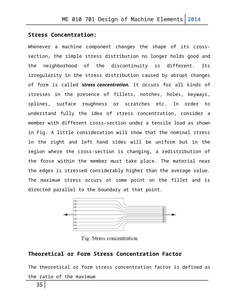
Stress Concentration:
Whenever a machine component changes the shape of its cross-section, the simple stress
distribution no longer holds good and the neighborhood of the discontinuity is different. Its
irregularity in the stress distribution caused by abrupt changes of form is called stress
concentration. It occurs for all kinds of stresses in the presence of fillets, notches, holes,
keyways, splines, surface roughness or scratches etc. In order to understand fully the idea of
stress concentration, consider a member with different cross-section under a tensile load as
shown in Fig. A little consideration will show that the nominal stress in the right and left hand
sides will be uniform but in the region where the cross-section is changing, a redistribution of the
force within the member must take place. The material near the edges is stressed considerably
higher than the average value. The maximum stress occurs at some point on the fillet and is
directed parallel to the boundary at that point.
Theoretical or Form Stress Concentration Factor
The theoretical or form stress concentration factor is defined as the ratio of the maximum
stress in a member (at a notch or a fillet) to the nominal stress at the same section based upon net
area. Mathematically, theoretical or form stress concentration factor,
Kt = Maximum stress/ Nominal stress
The value of Kt depends upon the material and geometry of the part. In static loading, stress
concentration in ductile materials is not so serious as in brittle materials, because in ductile
materials local deformation or yielding takes place which reduces the concentration. In brittle
materials, cracks may appear at these local concentrations of stress which will increase the stress
over the rest of the section. It is, therefore, necessary that in designing parts of brittle materials
23

ME 010 701 Design of Machine Elements 2014
such as castings, care should be taken. In order to avoid failure due to stress concentration, fillets
at the changes of section must be provided.
In cyclic loading, stress concentration in ductile materials is always serious because the ductility
of the material is not effective in relieving the concentration of stress caused by cracks, flaws,
surface roughness, or any sharp discontinuity in the geometrical form of the member. If the stress
at any point in a member is above the endurance limit of the material, a crack may develop under
the action of repeated load and the crack will lead to failure of the member.
Methods of Reducing Stress ConcentrationWhenever there is a change in cross-section, such as shoulders, holes, notches or keyways and
where there is an interference fit between a hub or bearing race and a shaft, then stress
concentration results. The presence of stress concentration cannot be totally eliminated but it
may be reduced to some extent. A device or concept that is useful in assisting a design engineer
to visualize the presence of stress concentration and how it may be mitigated is that of stress
flow lines, as shown in Fig.3. The mitigation of stress concentration means that the stress flow
lines shall maintain their spacing as far as possible.
In Fig. 3 (a) we see that stress lines tend to bunch up and cut very close to the sharp re –entrant
corner. In order to improve the situation, fillets may be provided, as shown in Fig. 3 (b) and (c)
to give more equally spaced flow lines.
24
ME 010 701 Design of Machine Elements 2014
25
ME 010 701 Design of Machine Elements 2014
Theories of FailureModern CADD systems allow the engineer to calculate stress levels in a component using finite
stress analysis linked to the model. The reasons why a given material fails however, is not
something a computer can predict without the results of research being added to its data bank. In
some cases it fails because the maximum tensile stress has been reached and in others because
the maximum shear stress has been reached. The exact combination of loads that makes a
component fail depends very much on the properties of the material such as ductility, grain
pattern and so on. This section is about some of the theories used to predict whether a complex
stress situation is safe or not. First we should consider what we regard as failure. Failure could be
regarded as when the material breaks or when the material yields. If a simple tensile test is
conducted on a ductile material, the stress strain curve may look like this.
The maximum allowable stress in a material is max. This might be regarded as the stress at
fracture (ultimate tensile stress), the stress at the yield point or the stress at the limit of
proportionality (often the same as the yield point). The Modulus of elasticity is defined as E =
stress/strain = / and this is only due up to the limit of proportionality. Note that some
materials do not have a proportional relationship at all. The maximum allowable stress may be
determined with a simple tensile test.
There is only one direct stress in a tensile test ( = F/A) so it follows that (max = 1 and it will
have a corresponding strain max=1. Complex stress theory tells us that there will be a shear
stress and strain that has a maximum value on a plane at 45° to the principal plane. It is of
26
ME 010 701 Design of Machine Elements 2014
interest to note that in a simple tensile test on a ductile material, at the point of failure, a cup and
cone is formed with the sides at 45° to the axis. Brittle materials often fail with no narrowing
(necking) but with a flat fail plane at 45° to the axis. This suggests that these materials fail due to
the maximum shear stress being reached.
Maximum Principal Stress Theory/Rankine Theory:
The theory states that the failure of the mechanical component subjected to bi-axial or tri-axial
stresses occurs when the maximum principal stress reaches the yield or ultimate strength of the
material.
If 1, 2 and 3 are the three principal stresses at a
point on the component and 1> 2 > 3 then according
to this theory, the failure occurs whenever
1=max or 1=ys
Whichever is applicable
The theory considers only the maximum of principal
stresses and disregards the influence of the other
principal stresses. The dimensions of the component
Maximum Shear Stress Theory/Guest Theory/ Tresca Theory :
This criterion of failure is accredited to CA Coulomb, H Tresca and JJ Guest.
27
ME 010 701 Design of Machine Elements 2014
The theory states that the failure of a mechanical component subjected to bi-axial or tri-axial
stresses occurs when the maximum shear stress at any point in the component becomes equal to
the maximum shear stress in the standard specimen of the tension test, when yielding starts.
In the tension test, the specimen is subjected
to uni-axial stress (1) and (2 = 0). The
stress in the specimen of tension test and the
corresponding Mohr's circle diagram are
shown in Figure above. From the figure,
❑max=12
When the specimen starts yielding (1 = ys),
the above equation is written as
❑max=❑ys
2
Therefore, the maximum shear stress theory predicts that the yield strength in shear is half of the
yield strength in tension.
Maximum principal strain theory/St. Venant’s Theory:
This theory is often called Saint Venant's theory because of the work of Barrc dc Saint Venant
(1767-1886), a great French mathematician and elastician. According to this theory, a ductile
material begins to yield when the maximum principal strain reaches the strain at which yielding
occurs in simple tension, or when the minimum principal strain (i.e. the compressive strain)
equals the yields point strain in simple compression.
28

ME 010 701 Design of Machine Elements 2014
Maximum Principal Strain Energy Theory/Haigh Theory:
This theory, originally put forward by Beltrami, is generally known as Haigh’s theory or
Beltrami-Haigh's theory. According to this theory, a body under complex stresses fails when the
total strain energy on the body is equal to the strain energy at elastic limit in simple tension.
According to this theory, if a body is brought to a particular state by various methods, then the
work done by passing from the initial to final state will be independent of the method applied.
Hence when a material is caused to take permanent set by stress which increase gradually from
zero, then the initial strain energy is independent of the nature of stresses and is almost constant
in value.
The theory states that inelastic action at any point in a body due to any state of stress begins only
when the energy per unit volume absorbed at the point is equal to the energy absorbed per unit
29
ME 010 701 Design of Machine Elements 2014
volume of the material when subjected to the elastic limit under a uniaxial state of stress, as
occurs in a simple tensile test.
Maximum Shear Strain Energy Theory/Von-Mises Theory:
This theory is frequently called the Huber-Henky-Von-Mises theory, as it was proposed by
M.T.Huber of Poland in 1904 and independently by R. Von Mises of Germany in 1913. This
theory differs from the maximum strain energy theory in that the portion of the strain energy,
producing volume change, is considered ineffective in causing failure by yielding. Supporting
evidence comes from the capacity of materials to withstand very high hydrostatic pressures. The
portion of strain energy producing change in shape of the element is assumed to be completely
responsible for the failure of the material by yielding.
The maximum shear strain energy theory, also known as energy of distortion theory states that
inelastic action at any point in a body under any combination of stresses begins when the strain
energy of distortion per unit volume absorbed at the point is equal to the strain energy of
distortion absorbed per unit volume at any point in a bar stressed to the elastic limit under the
state of uniaxial stress as occurs in a simple tension (or compression) test.
The energy of distortion can be obtained by subtracting the energy of volumetric change from
the total energy. Under a system of stresses acting externally on a body, the total external work
done causes (a) change in volume due to operation of direct stresses, and (b) distortion due to the
shearing stresses which does not affect the volumetric change.
30
ME 010 701 Design of Machine Elements 2014
Fatigue and Endurance Limit
31

ME 010 701 Design of Machine Elements 2014
32

ME 010 701 Design of Machine Elements 2014
33
ME 010 701 Design of Machine Elements 2014
34
ME 010 701 Design of Machine Elements 2014
35
ME 010 701 Design of Machine Elements 2014
36

ME 010 701 Design of Machine Elements 2014
37


