February 2006 DESIGN MANUAL FOR ROADS AND BRIDGES VOLUME 6 ROAD GEOMETRY SECTION 2 JUNCTIONS PART 1 TD 22/06 LAYOUT OF GRADE SEPARATED JUNCTIONS SUMMARY This standard sets out the design requirements and methodology for the geometric design and layout of grade separated junctions on trunk roads and motorways. It revises and combines the previous standard (TD 22/92) and advice note (TA 48/92). It takes into account the amendments included in the interim revision (TD 22/05). INSTRUCTIONS FOR USE 1. Remove Contents pages from Volume 6 and insert new Contents pages for Volume 6 dated February 2006. 2. Remove TD 22/05 from Volume 6, Section 2 which is superseded by this Standard and archive as appropriate. 3. Insert TD 22/06 into Volume 6, Section 2. 4. Please archive this sheet as appropriate. Note: A quarterly index with a full set of Volume Contents Pages is available separately from The Stationery Office Ltd.
Transcript
February 2006
DESIGN MANUAL FOR ROADS AND BRIDGES
VOLUME 6 ROAD GEOMETRYSECTION 2 JUNCTIONS
PART 1
TD 22/06
LAYOUT OF GRADE SEPARATEDJUNCTIONS
SUMMARY
This standard sets out the design requirements andmethodology for the geometric design and layout ofgrade separated junctions on trunk roads andmotorways. It revises and combines the previousstandard (TD 22/92) and advice note (TA 48/92). Ittakes into account the amendments included in theinterim revision (TD 22/05).
INSTRUCTIONS FOR USE
1. Remove Contents pages from Volume 6 andinsert new Contents pages for Volume 6 datedFebruary 2006.
2. Remove TD 22/05 from Volume 6, Section 2which is superseded by this Standard and archiveas appropriate.
3. Insert TD 22/06 into Volume 6, Section 2.
4. Please archive this sheet as appropriate.
Note: A quarterly index with a full set of VolumeContents Pages is available separately from TheStationery Office Ltd.
TD 22/06
Layout of GradeSeparated Junctions
Summary: This standard sets out the design requirements and methodology for thegeometric design and layout of grade separated junctions on trunk roads andmotorways. It revises and combines the previous standard (TD 22/92) andadvice note (TA 48/92). It takes into account the amendments included in theinterim revision (TD 22/05).
DESIGN MANUAL FOR ROADS AND BRIDGES
THE HIGHWAYS AGENCY
SCOTTISH EXECUTIVE
WELSH ASSEMBLY GOVERNMENTLLYWODRAETH CYNULLIAD CYMRU
THE DEPARTMENT FOR REGIONAL DEVELOPMENTNORTHERN IRELAND
Volume 6 Section 2Part 1 TD 22/06
February 2006
REGISTRATION OF AMENDMENTS
Amend Page No Signature & Date of Amend Page No Signature & Date ofNo incorporation of No incorporation of
amendments amendments
Registration of Amendments
Volume 6 Section 2Part 1 TD 22/06
February 2006
REGISTRATION OF AMENDMENTS
Amend Page No Signature & Date of Amend Page No Signature & Date ofNo incorporation of No incorporation of
amendments amendments
Registration of Amendments
VOLUME 6 ROAD GEOMETRYSECTION 2 JUNCTIONS
PART 1
TD 22/06
LAYOUT OF GRADE SEPARATEDJUNCTIONS
Contents
Chapter
1. Introduction
2. Design Procedure
3. Traffic Flows
4. Geometric Standards
5. Layout Options
6. Facilities for Non-Motorised Users
7. References
8. Enquiries
DESIGN MANUAL FOR ROADS AND BRIDGES
February 2006
Volume 6 Section 2Part 1 TD 22/06
Chapter 1Introduction
1. INTRODUCTION
General
1.1 This standard sets out the layout and sizerequirements for new and improved grade separatedjunctions and interchanges on rural and urban trunkroads and motorways. It sets out requirements for theprovision of weaving sections for traffic betweenjunctions. It gives guidance on access to and egressfrom service areas.
1.2 This standard does not cover the designrequirements and methodology for the geometric layoutof either major interchanges (including the expansionand improvement of existing interchanges andjunctions) or compact grade separated junctions(principally for use on rural and inter-urban roads).These are set out in TD 39 (DMRB 6.2.4) andTD 40 (DMRB 6.2.5).
1.3 Guidance on the structured process of choosingbetween junction types is given in advice noteTA 30 (DMRB 5.1).
1.4 The main changes from the previous standardand advice note are summarised as follows:
i This standard combines and supersedes theprevious standard TD 22/92 and the advice noteTA 48/92. It includes the revisions included inthe interim revision TD 22/05 (DMRB 6.2.1).
ii. Junctions onto connector roads are prohibited.
iii. New design requirements for diverge and mergeslip roads to ensure adequate length fordeceleration and acceleration.
iv. Existing two lane merges which are subject toimprovement must be altered to a one laneparallel merge or two lane ghost island merge asappropriate.
v. Introduction of the ghost island diverge layout(“tiger tail”).
vi. Principle of averaging for weaving lengths atghost island layouts.
vii. Comprehensive requirements for merge anddiverge layouts for Motorway Service Areas.
February 2006
viii. Revised requirements for determining hourlytraffic flows for design.
ix. Use of absolute maximum gradient on motorwayconnector roads of 6% is permitted.
x. Introduction of three types of loops.
xi. Clarification of the requirements for sightdistance for diverge and merge slip roads.
xii. Auxiliary lanes on climbing lane sections to beextended beyond crest to enable visibility of theend of the lane.
xiii. More guidance on facilities for non-motorisedusers.
Scope
1.5 This standard sets out the design requirementsand methodology for the geometric design of andchoice between different grade separated junctionlayouts on trunk roads and motorways. It draws on theexperience gained since the publication of the previousstandard (TD 22/92) and advice note (TA 48/92) andrevises and combines the two documents. It takes intoaccount the amendments included in the interimrevision (TD 22/05). It provides guidance on theprinciples for safety and traffic operation and on thechoice between different grade separated junctionlayouts. Recommendations are given on the siting ofgrade separated junctions in urban and rural areas,geometric design and the provision for non-motorisedusers. Some aspects of signs and road marking areincluded for completeness, although policy and detailedguidance on these matters are given in the Traffic SignsRegulations and General Directions (TSRGD), theTraffic Signs Manual, DMRB Volumes 8 and 9 andLocal Transport Note 1/94.
Implementation
1.6 This standard must be used forthwith for thedesign of all schemes for the construction andimprovement of all-purpose and motorway trunkroads currently being prepared, provided that in theopinion of the Overseeing Organisation, this wouldnot result in any significant additional expense or
1/1
Volume 6 Section 2Part 1 TD 22/06
Chapter 1Introduction
delay. The Design Organisation must confirm itsapplication to particular schemes with theOverseeing Organisation.
Definitions
1.7 The terminology used in this standard follows,where possible, the definitions contained in BS 6100:Subsection 2.4.1: 1992.
1.8 The following additional terms have beendefined for use in this Standard (see also Figure 1/1).
1.9 Auxiliary Lane: An additional lane at the side ofthe mainline carriageway to provide increased merge ordiverge opportunity or additional space for weavingtraffic. See Figure 2/4.1B and Figure 2/6.3D Option 2.
1.10 Connector Road: A collective term forinterchange links, link roads, slip roads and loops.
1.11 Design Organisation: The organisationcommissioned to undertake the various phases ofscheme preparation.
1.12 Downstream: That part of the carriageway(s)where the traffic is flowing away from the section inquestion.
1.13 Fork: An at-grade junction of two roads, usuallywithin an interchange, which diverge from the approachroad at similar angles. Usually both diverging roadshave equal status. (For a fork junction, as defined inBS 6100: Subsection 2.4.1, the minor road deviatesfrom the straight major road.) See Figure 4/6.
1.14 Ghost Island: An area of the carriagewaysuitably marked to separate lanes of traffic travelling inthe same direction on both merge and diverge layouts.The purpose of the ghost island at a merge is to separatethe points of entry of two slip road traffic lanes. At adiverge it is to separate the points of exit to a slip road.See Figures 2/4.4F, 2/6.1B Option 1 and 2/6.3DOption 1.
1.15 Interchange: A grade separated junction thatprovides free flow from one mainline to another.
1.16 Interchange Link: A connector road, one or twoway, carrying free flowing traffic within an interchangebetween one level and/or direction and another. SeeParagraphs 4.2 and 4.3.
1.1roacar
1.1uproa
1.1theton
1.2wamadircarsucadeclo
1.2is mFigranconlenor
1.2looDeas int
1.2flothe
1.2lesSu6.1
1.2shamefro
1.2autsch
1/2
7 Lane Gain: A layout where a merging connectord becomes a lane or lanes of the downstream mainriageway. See Figures 2/4.3E, 2/4.4F and 2/4.5G.
8 Lane Drop: A layout where a lane or lanes of thestream carriageway becomes the diverging connectord. See Figures 2/6.2C, 2/6.3D and 2/6.4E.
9 Large Goods Vehicle (LGV): A goods vehicle, permissible maximum weight of which exceeds 7.5nes.
0 Link Road: In the context of junctions, a oney connector road adjacent to but separate from theinline carriageway carrying traffic in the sameection, which is used to connect the mainlineriageway to the local highway network wherecessive direct connections cannot be provided to anquate standard because the junction spacing is toose. See Figure 5/6.
1 Loop: A connector road, one or two way, whichade up of the elements of the loops shown in
ure 4/1 and which passes through an angle in thege of approximately 180 to 270 degrees. The loop issidered to extend to the end of the near straightgth of road contiguous with the back of the divergemerge nose.
2 Low Radius: A radius between the minimump radius in Table 4/2 and the Two Steps belowsirable Minimum Radius with Superelevation of 7%required by TD 9 (DMRB 6.1.1) for the slip road orerchange link design speed.
3 Mainline: The carriageway carrying the mainw of traffic; generally traffic passing straight through junction or interchange.
4 Near Straight: A length of road with a radius nos than the Desirable Minimum Radius withperelevation of 5% as required by TD 9 (DMRB.1) for the mainline design speed.
5 Nose: A paved area, approximately triangular inpe, between a connector road and the mainline at arge or diverge, suitably marked to discourage driversm crossing it.
6 Overseeing Organisation: The highway or roadhority for the road construction or improvementeme.
February 2006
Volume 6 Section 2Part 1 TD 22/06
Chapter 1Introduction
1.27 Parallel Merge/Diverge: A layout where anauxiliary lane is provided alongside the mainlinecarriageway. See Figures 2/4.1B, 2/4.5H, 2/6.1BOption 2 and 2/6.3D Option 2.
1.28 Reserved Lane: A lane carrying traffic that issegregated from weaving traffic.
1.29 Rural Road: As defined in TA 46 (DMRB5.1.3), namely all-purpose roads and motorways that aregenerally not subject to a local speed limit.
1.30 Slip Road: A connector road within a junctionbetween a mainline carriageway and the local highwaynetwork, or vice versa, which meets the local highwaynetwork at-grade. Traffic using a slip road usually hasto give way to traffic already on the mainline or on thelocal highway network. See Paragraph 4.2.
1.31 Taper Merge/Diverge: A layout where mergingor diverging traffic joins or leaves the mainlinecarriageway through an area forming a funnel to or flarefrom the mainline carriageway. See Figures 2/4.1A and2/6.1A.
1.32 “Tiger Tail”: A ghost island layout at a divergeutilising TSRGD diagram 1042.1 to separate the pointsof exit to a slip road. So called because the vertical signused to inform drivers of the layout incorporates anillustration that resembles a tiger’s tail. SeeFigures 2/6.1B Option 1 and 2/6.3D Option 1.
1.33 Upstream: That part of the carriageway(s) wheretraffic is flowing towards the section in question.
1.34 Urban All-Purpose Road (UAP): An all-purpose road within a built up area, either a singlecarriageway with a speed limit of 40 mph or less or adual carriageway with a speed limit of 60 mph or less.
1.35 Urban Motorway: A motorway with a speedlimit of 60 mph or less within a built up area.
1.36 Weaving Section: The length of the carriagewaybetween a successive merge or lane gain and diverge orlane drop, where vehicles leaving the mainline at thediverge or lane drop have to cross the paths of vehiclesthat have joined the mainline at the merge or lane gain.See Figure 2/9 and Figures 4/9 to 4/14.
M
D
R
February 2006
andatory Sections
1.37 Mandatory sections of this document arecontained in boxes. The Design Organisation mustcomply with these sections or obtain agreement toa Departure from Standard from the OverseeingOrganisation. The remainder of the documentcontains advice and explanation, which iscommended to users for consideration.
epartures from Standards
1.38 In exceptional situations, the OverseeingOrganisation may be prepared to agree to aDeparture from Standard where the standard,including permitted Relaxations, is not realisticallyachievable. Design Organisations faced by suchsituations and wishing to consider pursuing thiscourse must discuss any such option at an earlystage in design with the Overseeing Organisation.Proposals to adopt Departures from Standard mustbe submitted by the Design Organisation to theOverseeing Organisation and formal approvalreceived before incorporation into a design layout.
elaxations
1.39 In difficult circumstances Relaxations maybe introduced at the discretion of the DesignOrganisation, having regard to all relevant localfactors, but only where specifically permitted bythis standard. Careful consideration must be givento layout options incorporating Relaxations, havingweighed the benefits and any potential disbenefits.Particular attention must be given to the safetyaspects (including operation, maintenance,construction and demolition) and theenvironmental and monetary benefits/disbenefitsthat would result from the use of Relaxations. Theconsideration process must be recorded. Thepreferred option must be compared against optionsthat would meet full standards.
1/3
Volume 6 Section 2Part 1 TD 22/06
1/4
Chapter 1Introduction
Taper Merge/Diverge and Parallel Merge/Diverge
Design details are given in Chapter 2 of this document.
Figure 1/1 Definition of Main Terms
February 2006
Volume 6 Section 2Part 1 TD 22/06
Chapter 2Design Procedure
2. DESIGN PROCEDURE
General Principles
2.1 Junction and Interchange design is an iterativeprocess which is a key part of the overall design processfor schemes. Figure 2/1 is a flowchart for junction andinterchange design. Figure 2/2 outlines the connectorroad design process.
2.2 The design of junctions is affected by decisionstaken on the degree of access to be provided on thescheme. It is important to consider from the outset howmuch access should be allowed. It may not be possibleto cater for the full predicted demand. The fact thatother roads are crossed, does not imply that a junctionshould be provided, or that if one is provided, it shouldbe omni-directional.
2.3 There may be occasions when the design shouldnot provide for certain movements to prevent use of thetrunk road by local commuters for the benefit of longerdistance traffic and for environmental reasons. Theprocess of choosing between options is covered morefully in TA 30 (DMRB 5.1).
2.4 A junction layout should give drivers and otherroad users a clear understanding of what is required ofthem. Poor layouts lead to driver confusion,indecisiveness and rash decisions that could contributeto accidents.
The design should provide:
• advance notification of the layout on theapproach to a junction;
• conspicuous junction locations and layouts;
• understanding of permitted changes to thedirection of travel;
• understanding of other traffic movements;
• avoidance of potential hazards.
Thus, in assembling the design components, designersshould ensure that as drivers approach a junction theyare able to easily perceive the junction form and layoutso that they can select their path through the junctionaccordingly. Ease of use should be checked for night-time conditions.
February 2006
2.5 It is important to ensure that adequate forwardvisibility is provided in accordance with TD 9 (DMRB6.1.1). The possible adverse effects on forwardvisibility of features such as mature vegetation, lightingcolumns, signs and vehicle restraint systems should beconsidered at an early stage in design. Drivers willmore readily understand the use of standard featuresthan unusual features and if it is necessary to useunusual features these should be well signed or bereadily understood.
2.6 Earthworks and landscaping should be an integralpart of junction design rather than an afterthought.
2.7 Design Organisations should consider thepotential for dazzle and silhouetting of signs when thesun is low in the sky. The designer should also attemptto avoid the need for drivers to approach a manoeuvreor a decision point looking into the rising or setting sun.
Urban/Rural
2.8 The design of grade separated junctions is basedon the design hourly flow which usually variesaccording to road type and according to whether theroad is motorway or all-purpose or rural or urban.Urban standards for most elements of road design are,however, lower than those applicable to rural design,since lower driver expectation accompanied by higherperception offset the increased risks caused byreductions in standards. For example, the presence ofkerbs, frequent lack of hardstrips, narrow centralreserve, lighting and speed limits would all indicate theurban nature of a road. The lower urban standards areshown within the hierarchy of geometric standards,ranging from rural motorways down to urban all-purpose roads, related to Design Speed (see Table 4/3and Table 4/4).
Location
2.9 The location of a grade separated junction canhave a significant effect on both its operationalperformance and environmental impact. Therefore,consideration of the major contributing issues should beundertaken at the initial design stage to produce theoptimum design for comparison with other junctiontypes. Some major contributing issues are listed inparagraph 5.4.
2/1
Volume 6 Section 2Part 1 TD 22/06
Chapter 2Design Procedure
Figure 2/1 Flow Chart Showing the Junction/Interchange Design Process
Determine Strategic Network and Design Year.
Decide whether urban or rural standards apply.
Decide initial strategy for network and junction.
Derive hourly traffic flows to be used for design, correcting for LGVs and gradients.
Confirm whether All-Purpose or Motorway using network strategy and TA46 or TA79 initialstandards.
Are lane requirements for mainline and connector roads achievable?
Are suitable merge/diverge and weaving layouts for the design flows achievable?
Is signing/motorway signalling possible?Are lane drop/gains satisfactory?Is junction spacing satisfactory?
Scheme preparation continues.
➤➤
➤➤
➤➤
➤➤
➤
➤
➤
➤
Yes
Yes
Yes
No
No
No
February 20062/2
Volume 6 Section 2Part 1 TD 22/06
Chapter 2Design Procedure
Safety
2.10 The main objective of grade separated junctiondesign is to provide a junction which is safe for theforecast traffic flows. Certain layouts are notrecommended for safety reasons and should be avoided.These are:
(i) grade separated junctions on single carriageways(see TD 9 (DMRB 6.1.1) and TD 40 (DMRB6.2.5));
(ii) grade separation on dual carriageways within0.5 km of a changeover to single carriagewaystandard, measured from the end of the mergetaper to the beginning of the right hand lanehatching that removes the offside lane or lanes(see The Traffic Signs Manual, Chapter 4 andTD 42 (DMRB 6.2.6));
(iii) offside merges and diverges;
(iv) major/minor junctions, particularly those withright turning movements, on an otherwise gradeseparated route.
Recommended Layouts
2.11 Recommended layouts for consideration in orderof increasing traffic flow level are:
i) diamond or half clover-leaf – simple priorityjunctions with the minor road;
ii) dumb-bell roundabout – junctions with the minorroad are provided by two normal roundaboutswhich are connected by a central link road eitherunder or over the mainline;
iii) two bridge roundabout – a single largeroundabout with the circulatory carriagewayeither under or over the mainline;
iv) 3 level roundabout – a junction usually betweentwo roads of similar flow. The two mainlines areon the upper and lower levels of the junction withthe roundabout on the central level;
v) interchange – a junction between major roadswith all movements catered for by free flowingconnector roads.
With the exception of the Interchange these junctionshave merge and diverge slip roads which may besignalised at their junction with the side road orroundabout.
2sS
TAa
To
To
ToR
TTR
Ac
T
2thsru1incju
2ppescPwp
2tomcthbneu
February 2006
.12 The design of an at-grade junction within a gradeeparated junction is subject to the appropriatetandards and Advice Notes as follows:
A 23 (DMRB 6.2) – (Advice Note – Junctions andccesses: Determination of the Size of Roundabouts
nd Major/Minor Junctions);
D 16 (DMRB 6.2.3) – (Standard – Geometric Designf Roundabouts);
D 50 (DMRB 6.2.3) – (Standard – Geometric Layoutf Signal-Controlled Junctions and Signalisedoundabouts);
D 51 (DMRB 6.3.5) – (Standard – Segregated Lefturn Lanes and Subsidiary Deflection Islands atoundabouts).
more detailed discussion of the layout options isontained in Chapter 5.
he Design Process
.13 Following through the flow-chart, (Figure 2/1)e first stages would be to determine a network
trategy, fix a design year, and decide whether urban orral standards apply (see paragraphs 1.29, 1.34 and
.35). The next stage would then be to decide on anitial network and junction strategy, including the
onnections to be made, for example whether thenction should be omni-directional.
.14 Having made those starting decisions, it isossible to derive hourly flows to be used in the designrocess following the guidance in Chapter 3. Anxamination of these flows, applied to the networktrategy adopted, will enable a decision to be taken (oronfirmed) that the route should be Motorway or All-urpose. Reference to TA 46 and TA 79 (DMRB 5.1.3),ill give a starting point on the level of carriagewayrovision for the links on the network assumed.
.15 The next stage, and the first step that could lead iteration, is to assess the likely lane provision on theainline and the connector roads. If the basic scheme
annot be tailored to cope with demands, includingose likely to arise when maintenance work needs to
e undertaken, then network and junction strategy willeed to be reviewed and alternatives investigated; forxample – reducing the number of junction accesses orsing link roads. Link roads reduce the frequency of
2/3
Volume 6 Section 2Part 1 TD 22/06
Chapter 2Design Procedure
direct access points along the mainline in order toeliminate sub-standard weaving lengths thus promotingfree flow to minimise the potential for accidents and topreserve the high capacity of the mainline. They canalso be used where it is unsafe or not possible to makedirect connections. Link roads can be useful formaintenance and diversions.
2.16 The following stage may also lead to iteration.This is to determine the merge and diverge facilities andto check that weaving sections at or above the desirableminimum length can be provided. If these cannot beachieved, then the junction strategy should be reviewed.
2.17 The next stage is to check that desirablegeometric standards can be achieved with the junctionspacing, and any lane gains or drops proposed, and thatan effective and economic signing system can beprovided. Again the strategy may have to be adjusted.Figure 2/2 is a flowchart showing the connector roaddesign process. It refers to the particular paragraphs,figures and tables of this standard applicable toconnector road design and to TD 27 (DMRB 6.1.2).
2.18 If the junction and interchange designs pass thesestages, the scheme can then be taken to the next stage inits preparation which is likely to be a cost/benefitassessment. Analysis may not be sufficiently fine toevaluate the performance of individual junctionelements. The best means of ensuring that a junction iseffective is to carry out the operational check outlinedabove and in Figure 2/1.
Junction and Interchange Design
General Principles
2.19 Where lane drops and lane gains occur, the laneconfigurations ahead should be made clear to drivers bythe consistent use of signs and road markings asoutlined in TSRGD and TA 58 (DMRB 8.2.1). Theseprinciples have been incorporated in the recommendedlayouts.
2.20 Where large traffic flows are joining the mainlinein an interchange or junction, turbulence can occur,with short headways and sudden braking. A length ofauxiliary lane may be necessary to provide increasedlocal capacity. This is covered more fully in paragraphs4.23 to 4.26.
2.21 The signing of junctions and interchanges shouldgive clear and timely information to drivers. This isparticularly important at lane gains and lane drops and
atvlopsT
2nyep
2aTba
M
2icnom
2tmefbt
2temeia
2gnpl
2/4
t other decision type locations or in situations wherehe driver’s view may be obstructed by high trafficolumes or large proportions of LGVs. At theseocations consideration should be given to the provisionf gantries to mount the signs. Where these areroposed the design of the junction or interchangehould take the siting of the gantries into account, (seeD 18 (DMRB 9.1)).
.22 It may also be that the predicted turning flows areot realised in the proportions expected in the designear and the consequences of being wrong should bexamined. Sensitivity testing of differing flowroportions should be undertaken.
.23 Correction factors to take account of gradientsnd proportion of large goods vehicles, as detailed inables 3/2 and 3/3, may need to be made to the flows toe entered in Tables 3/1a and 3/1b, and Figures 2/3, 2/5nd 4/14.
erges – General Principles
.24 It is important on safety grounds and to limitnterference to mainline traffic that joining traffic ishannelled into the merging area (i.e. from the tip of theose to the end of the taper(s)) and arrives there in anrderly fashion to perform a safe and comfortableerge with the mainline.
.25 If joining flows are greater than one lane capacityhen an additional lane should normally be added to theainline as a lane gain. The individual merging area for
ach joining lane within a merge should be separatedrom the previous one and there should be spaceetween them for mainline traffic to adjust to the newraffic flow.
.26 Where design flows are close to capacity on bothhe connector road and on the mainline it is important tonsure that there is adequate provision for thoseerging. If the availability of merging opportunities is
stimated to be low for long periods of the day,mproved merging opportunities could be provided byuxiliary lanes.
.27 There may be occasions when the merge flow isreater than the mainline flow. The junction shouldevertheless be set out so that mainline traffic hasriority over traffic entering from the left, except at aane gain.
February 2006
Volume 6 Section 2Part 1 TD 22/06
Chapter 2Design Procedure
Determine junction location
Determine junction option
Check proposed location for driver perception (Paragraph 2.4)
Check protection of scheme elements and allow adequate spacewithin scheme to preserve sightlines (Paragraph 2.5)
Determine flows (Chapter 3) having used adjustment factorsfor LGVs and gradient.
Determine cross sections for AP or MW(Tables 3/1a and 3/1b, TD 27 (DMRB 6.1.2)) and paragraph 3.5
Merge Diverge
Enter merge flow in Figure 2/3 on the Enter diverge flow in Figure 2/5 on thevertical axis and the upstream mainline flow vertical axis and the downstream mainline
on the horizontal axis and read off the flow on the horizontal axis and read off theappropriate layout at the intersection point appropriate layout at the intersection point
(see Figure 2/4) (see Figure 2/6)
Determine if there is a need for auxiliary lanes Determine if there is a need for auxiliary lanes
Check widths of any ghost islands Check widths of any ghost islands(see Paragraph 2.32) (see Paragraph 2.53)
Determine the lengths of slip roads Determine the lengths of slip roads(see Paragraph 2.34) (see Paragraph 2.46)
Determine design parameters of the elements Determine design parameters of the elementsof the design (see Table 4/3) of the design (see Tables 4/4, 4/5)
Figure 2/2 Flow Chart Showing the Connector Road Design Process
➤➤
➤➤
➤➤
➤ ➤➤
➤➤
➤➤
➤
➤➤
➤➤
➤
February 2006 2/5
Volume 6 Section 2Part 1 TD 22/06
Chapter 2Design Procedure
2.28 There are many sites throughout the networkthat have a two-lane taper merge layout; suchlayouts are not now recommended. When junctionsthat contain these features are to be improved, thelayout must be altered to a standard layout asappropriate for the merge and mainline flow levels.When urban two lane taper merge layouts are to beimproved, Figure 2/4.2, layout D must be used.Ghost island merge layouts must not be used onurban roads.
Designing Merges
2.29 Hourly flows, as determined from Chapter 3for the merge and the mainline upstream must beinserted in Figure 2/3 to select a merge layout asshown in Figures 2/4.1 to 2/4.5. Where designflows lie close to, or on, a boundary between theflow regions, the probability of the particular flowactually occurring should be carefully reviewed.The provision of a layout that differs from thatderived from the use of Figure 2/3 is a departurefrom standard, whether the proposed design is anunder or over provision.
2.30 Where, for reasons of route continuity, themainline capacity provided is in excess of the designflows and a merging design flow of over one lanecapacity is expected, then layout C of Figure 2/4.2 maybe substituted for layout F of Figure 2/4.4, butnormally, with such a large flow expected to merge, alane would be added to the mainline. For layout C themeaning of ‘where design flows on the mainline arelight’ (see Figure 2/4.2) is that there is sufficientcapacity on the mainline to accept the flow from theslip road. Layout H (see Figure 2/4.5) may beconsidered as a departure from standards where it is notpossible to use Layout F (see also paragraph 4.29). ForFigure 2/4.4 layout F, Option 1 is the preferred optiondue to the likely usage of Lane 1 of the connector roadby the majority of large and/or slow vehicles and Lane2 predominantly by light vehicles. Option 2 has beenretained for use in circumstances where it isappropriate.
2.31 Ghost island road markings should be designedin accordance with TSRGD diagram 1042.1.
2.322.0m aa chevghost be tooof ghocould prevenghost from tshouldrequirestandarequireprovid
2.33will nogiven layoutfor insserviceparagr
2.34trafficthe mastraighgiven Road Cof the mergin
2.35cannotprovidcombidepart
2.36 Plajunctions can have especiallymainline congestioprogram stheir impa
2/6
The minimum width of a ghost island ist its widest point and the minimum width ofron is 0.5m (TSRGD diagram 1042.1). If theisland marking is less than 1.2m wide it will narrow to mark with chevrons. The lengthst island that is unmarked with a chevronextend over a long distance. In order tot this problem, the minimum width of a
island must be 1.2m at a distance of 50mhe tip of the ghost island head or tail. It be noted that ghost island layouts can significant length to comply with the
rd and this may be reflected in the landment especially where the layout is beinged within an existing highway boundary.
The minimum length of a merge slip roadrmally be dictated by the requirements
at paragraph 2.29 and the topographical of a junction. Where this is not the case, astance at the merge slip road leading out of a area, then the requirements set out in
aph 2.34 must be followed.
Gap finding is assisted when the merging has the opportunity to match the speed ofinline traffic. For all connector roads, a neart at least equal in length to the nose lengthin Table 4/3 column (3) for the appropriate
lass must be provided upstream of the backmerge nose. This requirement will enableg traffic to achieve a matching speed.
Where the required length of near straight be achieved, it may be appropriate toe an auxiliary lane instead or innation. An application must be made for aure from standard.
toons of traffic can enter a merge slip road ifupstream are signal-controlled. This traffica significant effect on the mainline flow at peak times when available gaps in thetraffic flow are few. Turbulence andn are the result. Care should be taken touch traffic signals with a view to reducingct on the mainline flow.
February 2006
Volume 6 Section 2Part 1 TD 22/06
Chapter 2Design Procedure
Notes:
# Area of uncertainty – In this area the choice will depend on the downstream provision. If there is a lane gainthen use Layout E or F.
See paragraph 2.29 and the example above, for explanation of the usage of this diagram.
Figure 2/3 AP All-Purpose Road Merging Diagram
February 2006 2/7
Volume 6 Section 2Part 1 TD 22/06
Chapter 2Design Procedure
Notes:
* If Layout F Option 2 is used consider extended Auxiliary Lane (see paragraph 4.23).
# Area of uncertainty – In this area the choice will depend on the downstream provision. If there is a lane gainthen use Layout E or F.
See paragraph 2.29 and example above, for explanation of the usage of this diagram.
Figure 2/3 MW Motorway Merging Diagram
February 20062/8
Volume 6 Section 2
Part 1 TD
22/06
February 2006
N.B
. Figures in brackets refer to columns in Table 4/3
Figure 2/4.1 Merge L
ane Layouts for use w
ith Figure 2/3
2/9
Chapter 2
Design Procedure
Volume 6 Section 2
Part 1 TD
22/06
2/10
Chapter 2
Design Procedure
February 2006
N.B
. Figures in brackets refer to columns in Table 4/3
Figure 2/4.2 Merge L
ane Layouts for use w
ith Figure 2/3
Volume 6 Section 2
Part 1 TD
22/06
February 2006
N.B
. Figures in brackets refer to columns in Table 4/3
Figure 2/4.3 Merge L
ane Layouts for use w
ith Figure 2/3
2/11
Chapter 2
Design Procedure
Volume 6 Section 2
Part 1 TD
22/06
February 20062/12
Chapter 2
Design Procedure
N.B
. Figures in brackets refer to columns in Table 4/3
Figure 2/4.4 Merge L
ane Layouts for use w
ith Figure 2/3
Volume 6 Section 2
Part 1 TD
22/06
February 20062/13
Chapter 2
Design Procedure
N.B
. Figures in brackets refer to columns in Table 4/3
Figure 2/4.5 Merge L
ane Layouts for use w
ith Figure 2/3
Volume 6 Section 2Part 1 TD 22/06
Chapter 2Design Procedure
Ramp Metering
2.37 Ramp metering is a remedial measure to improvethe flow of traffic on a mainline by controlling trafficentering from the slip road. Currently it is only used onmotorways. Traffic signals installed on motorway entryslip roads control vehicle flow on to the maincarriageway at a ‘metered’ rate. The traffic signals arelinked to sensors which measure speed, flow and laneoccupancy rates of traffic using the motorway andidentify an appropriate metering rate for the trafficconditions.
2.38 The use of ramp metering is still being tested atselected sites in England and the initial signs are that itincreases the flow of traffic on the motorway byreducing congestion that results from merging traffic.
2.39 Guidance on the use of ramp metering onexisting slip roads is available from the OverseeingOrganisation.
Diverges – General Principles
2.40 Diverging traffic should be able to leave themainline easily and without impeding the progress ofthrough traffic.
2.41 There is potential for accidents on divergeconnector roads if the capacity of the connection tothe local road network is insufficient and causesqueuing on the connector road. Drivers leaving themainline should have sufficient time to react andbrake safely before the end of any queue. Thedesigner must therefore ensure that thedownstream cross-section (designed in accordancewith TD 27 (DMRB 6.1.2)) and junctions (seeDMRB 6.2) do not cause queues that approach theback of the diverge nose. This will allow drivers touse the diverge area and length of nose todecelerate in reasonable comfort, as intended.
2.42 For existing junctions, if even after improvementto the downstream connection to the local roadnetwork, there is a likelihood of queuing extendingback onto the mainline carriageway, then auxiliarylanes should be considered as an exceptional case sothat queues occur off the mainline. Motorway IncidentDetection and Automatic Signalling (MIDAS) shouldalso be considered in such circumstances. Whenauxiliary lanes are specified in this situation a departurefrom standards approval will be required.
Des
2/14
igning Diverges
2.43 Hourly flows, as determined from Chapter 3for the diverge and the mainline downstream mustbe inserted in Figure 2/5 to select a diverge layoutas shown in Figures 2/6.1 to 2/6.4. Where designflows lie close to, or on, a boundary between theflow regions, the probability of the particular flowactually occurring should be carefully reviewed.The provision of a layout that differs from thatderived from the use of Figure 2/5 is a departurefrom standard, whether the proposed design is anunder or over provision.
2.44 The provision of a Layout B parallel diverge(Option 2) on a 4-lane mainline would create a6-lane carriageway, contrary to the requirements ofTD 27 (DMRB 6.1.2). Any proposal for such alayout must be referred to the OverseeingOrganisation.
2.45 The minimum length of a diverge slip roadwill normally be dictated by the requirementsgiven at paragraphs 2.41 and 2.43 and thetopographical layout of a junction. Where this isnot the case, as for instance at the diverge slip roadleading into a service area, then the requirementsset out in paragraph 2.46 must be followed.
2.46 For all connector roads, a near straight atleast equal in length to the nose length given inTable 4/4 column (4) for the appropriate RoadClass must be provided downstream of the back ofthe diverge nose. This requirement will enabledrivers to comprehend the layout ahead and adjusttheir speed accordingly.
2.47 Where the required length of Near Straightcannot be achieved, it may be appropriate toprovide an auxiliary lane instead or incombination. An application must be made for adeparture from standard.
2.48 For diverges, the layout of the edge linemust incorporate the radii shown on Figure 2/6.
February 2006
Volume 6 Section 2Part 1 TD 22/06
Chapter 2Design Procedure
Ghost Island Diverges
2.49 Ghost Island diverge layouts are preferred to theequivalent auxiliary lane layouts and should be selectedin preference to the auxiliary lane layouts except wherethe Ghost Island layout may be unsuitable (seeparagraph 2.52).
2.50 Ghost Island diverge layouts are for use when thediverge flow is high and are designed to reduce thelikelihood of queues of slow moving traffic in Lane 1together with ‘swooping’ movements (late manoeuvresfrom Lane 2 or 3) to the slip road. By providing twoaccess points to a two-lane exit slip road, the capacityof the diverge is increased, congestion on the mainlineis reduced and swooping is discouraged.
2.51 A full sequence of gantry direction signingis essential for a Ghost Island diverge layout. TheOverseeing Organisation should be consulted forguidance on the provision and location of sign andsignal gantries. In addition, it is essential thatdrivers are informed of the behaviour expected at aGhost Island diverge. Two verge-mounted advancedirection signs, to the design illustrated in Figure2/7, must be provided. The first of these signs willbe between the 1 mile gantry and the ½ milegantry; the second sign will be between the ½ milegantry and the final gantry. The main objective ofthese signs is to highlight to drivers the existenceof the second exit point and encourage its use. Ithas been found that the installation of these verge-mounted signs improves the utilisation of thesecond exit with the effect of balancing the vehicleflows on the slip road lanes. Signs authorisationwill be required for the non-standard signsdesigned for a particular site.
2.52 There may be occasions when the Ghost Islanddiverge layout is not suitable, for instance if signing isdifficult to implement or if a high turning movement atthe junction downstream of the diverge may lead to sliproad queues in one or more lanes tailing back towardsthe mainline (see paragraphs 2.40, 2.41 and 2.42); insuch cases the auxiliary lane layouts may be usedinstead. Note that for a Lane Drop at Parallel Diverge(Figure 2/6.3 Layout D Option 2), a full sequence ofgantry direction signing should be provided in order toencourage utilisation of Lane 2 by diverging traffic. Todate, ghost island diverges have been used only on ruralmotorways. For the application of ghost island divergelayouts to other roads, guidance should be sought from
February 2006
the relevant Overseeing Organisation. The layouts havealso been developed for use at existing junctions andthere may be constraints at a particular site that preventthe dimensions of the recommended layouts from beingachieved. Designers may need to consider amendmentsto the lengths and widths of the various elements of thelayouts. Where there are land constraints, for example,encroaching on the hardshoulder may be considered anacceptable means of achieving the additional capacityand safety offered by a ghost island diverge layoutsubject to obtaining agreement to a departure fromstandard. Figures 2/8(i) and 2/8(ii) are examples of theconversion of existing layouts. Note that these layoutsalso require provision of a full sequence of gantrydirection signing plus two verge-mounted signs to thedesign illustrated in Figure 2/7.
2.53 The minimum width of a ghost island is2.0m at its widest point and the minimum width ofa chevron is 0.5m (TSRGD diagram 1042.1). If theghost island marking is less than 1.2m wide it willbe too narrow to mark with chevrons. The lengthof ghost island that is unmarked with a chevroncould extend over a long distance. In order toprevent this problem, the width of a ghost islandmust be not less than 1.2m at a distance of 50mfrom the tip of the ghost island head or tail. Itshould be noted that ghost island layouts canrequire significant length to comply with thestandard and this may be reflected in the landrequirement especially where the layout is beingprovided within an existing highway boundary.
2/15
Volume 6 Section 2Part 1 TD 22/06
Chapter 2Design Procedure
Notes:
See paragraph 2.43 and the example above, for explanation of the usage of this diagram.
Figure 2/5 AP All-Purpose Road Diverging Diagram
Example of use of Figure 2/5APGiven a downstream main line flow4000vph and diverge flow 2000vph.
1 strike a perpendicular from4000vph on the horizontal axis
2 strike a perpendicular from2000vph on the vertical axis
3 the intersection point giveslayout type D which alsorequires a lane drop (seeUpstream Mainline axis above)
February 20062/16
Volume 6 Section 2Part 1 TD 22/06
Chapter 2Design Procedure
Notes:
* If Layout D Option 2 is used consider extended Auxiliary Lane (see paragraph 4.24).
See paragraph 2.43 and the example above, for explanation of the usage of this diagram.
Figure 2/5 MW Motorway Diverging Diagram
Example of use of Figure 2/5MWGiven a downstream main line flow4000vph and diverge flow 2000vph.
1 strike a perpendicular from4000vph on the horizontal axis
2 strike a perpendicular from2000vph on the vertical axis
3 the intersection point giveslayout type D which alsorequires a lane drop (seeUpstream Mainline axis above)
February 2006 2/17
Volume 6 Section 2
Part 1 TD
22/06
2/18
Chapter 2
Design Procedure
February 2006
N.B
. Figures in brackets refer to columns in Table 4/4
Figure 2/6.1 Diverge L
ane Layouts for use w
ith Figure 2/5
Volume 6 Section 2
Part 1 TD
22/06
February 2006
Figure 2/6.2 Diverge L
ane Layouts for use w
ith Figure 2/5
2/19
Chapter 2
Design Procedure
N.B
. Figures in brackets refer to columns in Table 4/4
Volume 6 Section 2
Part 1 TD
22/06
February 20062/20
Chapter 2
Design Procedure
N.B
. Figures in brackets refer to columns in Table 4/4
Figure 2/6.3 Diverge L
ane Layouts for use w
ith Figure 2/5
Volume 6 Section 2
Part 1 TD
22/06
February 20062/21
Chapter 2
Design Procedure
N.B
. Figures in brackets refer to columns in Table 4/4
Figure 2/6.4 Diverge L
ane Layouts for use w
ith Figure 2/5
Volume 6 Section 2Part 1 TD 22/06
Chapter 2Design Procedure
Motorway Service Areas (MSAs)
2.54 The merge and diverge layout design andjunction spacing parameters in this standard applyto MSAs.
2.55 Generally all vehicle types are permitted to enteran MSA via a connector road directly from the mainlineor as an integral part of a grade separated junction.
2.56 Drivers wishing to make a stop at MSAs willhave made a choice about their immediate destinationand know that they will have to slow down. Theprovisions set out below should facilitate safe layoutsfor access to and egress from MSAs.
Figure 2/7 Typical Sign for Ghost Island Diverge Layout (“tiger-tail”)
February 20062/22
Volume 6 Section 2
Part 1 TD
22/06
February 20062/23
Chapter 2
Design Procedure
Figure 2/8 Exam
ples of Existing Parallel D
iverges Converted to G
host Island Diverges
Volume 6 Section 2Part 1 TD 22/06
Chapter 2Design Procedure
2.57 The following requirements must apply toMSAs accessed directly from motorways:
• The design speed of connector roads mustbe the same as a slip road in Table 4/1.
• For diverge slip roads for MSAs, stoppingsight distance and horizontal curvature maybe reduced by one design speed step as aRelaxation (see paragraph 1.39 and TD 9(DMRB 6.1.1)).
• Near straights must be provided on the sliproads as described in paragraph 2.34 formerges and paragraph 2.46 for diverges.
• Street Lighting (see also paragraphs 5.33,5.34 and 5.35):
– If the mainline is lit then the slip roadmust be lit
– If the mainline is not lit then:
~ for a merge, the lighting mustbe ended as soon as possibleafter the MSA boundary;
~ for a diverge, the lighting muststart before the point whereMSA lighting occurs but suchas not to cause light spillageonto the mainline.
• The layout must include a comprehensivetraffic sign and road marking scheme andconsideration should be given to theinclusion of ‘chevron’ warning signs,reflective road studs, edge of carriagewaymarkings, rumble strips and advisory speedlimit signs.
• High containment kerbs must not be used onslip roads as high speed impacts may lead tothe overturning of vehicles.
• Measures must be taken to reduce any ‘see-through’ effects when looking from adiverge slip to the merge slip or internalroad system of the MSA, e.g. suitablelandscaping.
2deasgeio
2smmp
2tgw
O
2pgpa
A
D
2awAcmd
2dc
2/24
.58 For online service areas, at the end of the MSAiverge slip road, it is recommended that a gateway berected. The object of the gateway is to draw thettention of the driver to the change to the lowertandards of the MSA. It will also highlight the need forreater care and emphasise the probability ofncountering slow vehicles and pedestrians using thenternal roads of the MSA. The gateway must be sitedn the MSA side of the ‘End of Motorway’ signs.
.59 The gateway should include speed restrictionigns, which may be emphasised by the use of calmingeasures such as dragon’s teeth and coloured roadarkings. Additional gateway features may also be used
rovided that they do not create a road safety hazard.
.60 A similar or simpler gateway may be provided athe start of a merge slip road on leaving the MSA. Theateway must be sited on the MSA side of the pointhere the motorway regulations start.
ther Service Areas
.61 The merge and diverge layout design of all-urpose road service areas should be based on theeometric parameters within this standard as set out inaragraph 2.57 above or TD 42 (DMRB 6.2.6), asppropriate for each site.
pplication to Maintenance Compounds
2.62 Where maintenance compounds areaccessed off the mainline, the standards set out inparagraph 2.57 for MSAs must be used.
esign for Maintenance
.63 Any area of pavement that can be driven over inn emergency or during maintenance or other roadorks should be designed to make it safe to do so.lthough it is illegal to drive over noses and other
hevron areas bounded by continuous edge lines, theyay be trafficked during road works if drivers are
irected to do so.
.64 Paragraph 4.32 gives advice relating to lanerops and lane gains and the intervening length ofarriageway through a junction.
February 2006
Volume 6 Section 2Part 1 TD 22/06
Chapter 2Design Procedure
Emergency and Maintenance Accesses
2.65 Where an emergency or maintenance accessis required, a suitable layout must be chosen fromTD 41 (DMRB 6.2.7). The preferred layout is thatshown as Layout 1 but the designer must checkthat this would be adequate for its likely use. Theaccess must be gated and locked to preventunauthorised use. The entrance gate or gates mustbe set back to accommodate, behind the hardstripor hardshoulder, one vehicle of the largest typeexpected to use the access. For a maintenanceaccess, provision must be made for two vehicles ofthe largest type expected to use the access to passin opposite directions in the vicinity of the access.The design of the emergency or maintenanceaccess must comply with the requirements ofTD 41 (DMRB 6.2.7) with respect to avoidingsteep gradients on the access road in the immediatevicinity of its connection to the trunk road.
Designing Weaving Sections
2.66 The principle of calculating weaving sections isthat the length is fixed using paragraphs 4.34 to 4.37and the width is calculated from the formula inparagraph 2.71. This determines the number of lanesand can indicate the addition of one or two auxiliarylanes. The formula shows that the minor weaving flowhas an impact on the traffic demand of up to 3 times itsnumerical value.
2.67 An actual weaving length less than thedesirable minimum must not be entered into theformula.
2.68 Weaving lengths for taper layouts must bemeasured between the end of the merge and startof the diverge tapers, see Figure 4/9A. Forauxiliary lane layouts, the auxiliary lane is ignoredand the length between the end of the notionalmerge and and the start of the notional divergemust be measured as illustrated in Figure 4/9B. Inthe case of lane gains and lane drops, the methodsset out in Figures 4/10, 4/11 and 4/12 must beused.
2cadlaLdptrin
February 2006
2.69 In the case of ghost island merges anddiverges, the examples in Figure 4/13 show thetwo points which must be used for the twoconnector road lanes to provide the averagedweaving lengths between junctions. Similartechniques must be applied for diverges.
.70 In the case of wide (5 lane or more)rriageways, there should be no reduction below the
esirable minimum weaving length. A vehicle on a 5-ne carriageway requires at least 1km to cross betweenanes 5 and 1 in safety to leave at a diverge and theriver will need advance warning. The formula inaragraph 2.71 should still be used, but non-weavingaffic may be excluded from the calculation if it travels a reserved lane.
2.71 For weaving sections on motorways anddual carriageway roads, design flows must becalculated as in Chapter 3. In measuring Lact, it willbe necessary to consider whether distance isavailable to adequately sign the second junctionand allow adequate visibility to the sign from alllanes. To calculate the number of traffic lanesrequired for weaving the following equation mustbe used (and see Figure 2/9):
N = 1 (Qnw+Qw1+Qw2 (2 Lmin/Lact + 1)) D
Where N = Number of traffic lanes
Qnw = Total non-weaving flow in vph
Qw1 = Major weaving flow in vph
Qw2 = Minor weaving flow in vph
D = Maximum mainline flow fromparagraph 3.3 in vph per lane
Lmin = Desirable Minimum weavinglength for the road class as inparagraphs 4.34 to 4.37
Lact = Actual weaving lengthavailable
(Lact must always be greater than orequal to Lmin)
2/25
Volume 6 Section 2Part 1 TD 22/06
Ter
Chapter 2Design Procedure
.s
a
g
e
Figure 2/9
2.72 In calculating the number of traffic lanesrequired (paragraph 2.71) a fractional part willinevitably require a decision to round up or downIf it is possible to vary the position of the junctionand thus increase or decrease the weaving length,the fractional part will converge approximately towhole number of lanes and the decision issimplified. However, if this is not possible thedecision becomes more difficult. Where thefractional part is small and is combined with a lowweaving flow rounding down is suggested,whereas a high fractional part with a high weavinvolume suggests rounding up. For example theaddition of a fourth lane would have operationaladvantages in releasing the two middle lanes forweaving traffic. Other factors which may influencthe decision are:
2/26
ms used in Weaving
i the number of lanes required for mergingand diverging (paragraphs 2.29 and 2.43);
ii when the fractional part is about 0.5 theuncertainty of the design flows (Chapter 3)suggests always rounding up from 2 to 3lanes;
iii on recreational routes there can be a highproportion of drivers who are not local andtherefore behave less efficiently thancommuters would at the same flow levels;
iv the consequences of under provision shouldbe borne in mind, as the acquisition of landat a later date could be costly or impossible;
v. relevant environmental factors should betaken into account.
Qnw (non-weaving flow)= Flow 1 + Flow 4
Qw1 (major weaving flow)= greater of
Flow 2 or Flow 3Qw2 (minor weaving flow)
= lesser ofFlow 2 or Flow 3
February 2006
Volume 6 Section 2Part 1 TD 22/06
Chapter 3Traffic Flows
3. TRAFFIC FLOWS
Introduction
3.1 At the time of publishing this standard, theprocedure for determining traffic flows for use indesign is undergoing change and development.
3.2 Until such time as guidance has beenpublished, designers must contact the OverseeingOrganisation for instructions on how to proceed forindividual schemes.
3.3 The Highway Code advises that a minimumtwo-second headway should be maintainedbetween vehicles on roads carrying fast traffic. Forthe purpose of designing grade separated junctionsand interchanges, the maximum flow per lane formotorways must be taken as 1,800 vehicles perhour (vph) and for all-purpose roads as 1,600 vph.These flows do not represent the maximum hourlythroughputs but flows greater than these willusually be associated with decreasing levels ofservice and safety. These values have been used inFigures 2/3 and 2/5 in this standard.
Design Flow Ranges and Connector Road CrossSections
3.4 Connector road cross sections are set out inTD 27 (DMRB 6.1.2) and the correspondingdesign traffic flow ranges are given in Tables 3/1aand 3/1b.
3.5 Designers should consider the possible benefitsof providing greater widths for connector roads thanthose derived solely from Tables 3/1a and 3/1b and thestandard cross-sections in TD 27 (DMRB 6.1.2). Thiswould be, for example, to provide for futuremaintenance activities.
0-900 MG1A MG1B DG1A DG1B IL1A IL1BSingle lane Single lane Single lane Single lane Single lane* Single lane*
with with with with with withhardshoulder hardshoulder hardshoulder hardshoulder hardshoulder hardshoulder
901-1350 MG1A MG1B DG2A DG2B IL1A IL1BSingle lane Single lane Two lanes Two lanes Single lane* Single lane*
with with with with with withhardshoulder hardshoulder hardstrip hardstrip hardshoulder hardshoulder
1351-2700 MG2C MG2D DG2A DG2B IL2A IL2BTwo lanes Two lanes Two lanes Two lanes Two lanes Two lanes
with with urban with with with with urbanhardshoulder hardshoulder hardstrip hardstrip hardshoulder hardshoulder
2701-3600 MG2C MG2D DG2C DG2D IL2A IL2BTwo lanes Two lanes Two lanes Two lanes Two lanes Two lanes
with with urban with with urban with with urbanhardshoulder hardshoulder hardshoulder hardshoulder hardshoulder hardshoulder
Table 3/1b Cross-Sections for Connector Roads To/From Mainline Motorways
Notes For Tables 3/1a and 3/1b* See paragraph 4.3 for restrictions on use of single lane interchange links+ Design flow (vehicles per hour) adjusted for gradients and LGVsRefer to TD 27 (DMRB 6.1.2) for actual dimensions of cross-section componentsThese tables can indicate, for low connector road flows, that a single lane connector road should be provided for aLayout C diverge, which has two connector road lanes. In such cases, two lanes should be provided.
February 20063/2
Volume 6 Section 2Part 1 TD 22/06
Chapter 3Traffic Flows
Flow Adjustments for Uphill Gradients and forLGVs
3.6 Before using Figures 2/3 and 2/5 for theselection of merge and diverge layoutsrespectively, the design flows must be adjusted foruphill gradients and the presence of LGVs byusing Tables 3/2 and 3/3. Note that adjustments aremade to flows on the mainline and on mergeconnector roads but not to flows on divergeconnector roads.
3.7 To establish the mainline gradient at mergesor diverges, a 1 kilometre section must be used,0.5 km either side of the merge or diverge nose tip,and the average gradient determined. The mergeconnector road gradient must be based on theaverage of the 0.5 km section before the nose tip.
3.8 Before using Figure 4/14 and the weavingformula in paragraph 2.71, the design flows mustbe adjusted for uphill gradients and the presence ofLGVs by using Table 3/2.
3.9 To establish the mainline gradient at aweaving section, the weaving length, Lact, must bedetermined and the average gradient calculatedover that length.
%LGVs Mainline Gradienton mainline
<2% ≥2%
5 – 1.10
10 – 1.15
15 – 1.20
20 1.05 1.25
Table 3/2 Adjustment Factors for UphillGradients and for the presence of Large
Goods VehiclesMainline
C
February 2006
% LGVs Merge Connector Gradienton Merge
onnector<2% 2% – 4% >4%
5 – 1.15 1.30
10 – 1.20 1.35
15 1.05 1.25 1.40
20 1.10 1.30 1.45
Table 3/3 Adjustment Factors for UphillGradients and for the presence of Large
Goods VehiclesMerge Connector
3/3
Volume 6 Section 2Part 1 TD 22/06
Chapter 4Geometric Standards
DS
4. GEOMETRIC STANDAR
Cross Sections
4.1 For the purpose of designing junctions andinterchanges, cross sections for the mainline and allconnector roads are given in TD 27 (DMRB 6.1.2). Thedesign flow ranges corresponding to these crosssections are shown in Table 3/1a and 3/1b.
Maximum Lengths of Slip Roads and InterchangeLinks
4.2 A Slip Road longer than 0.75 km must bedesigned as an Interchange Link.
4.3 Single Lane Interchange Links must only beprovided:
• when their length does not exceed 1 km andthey are on an average uphill grade of up to3%, are level or on a downhill grade; or
• where their length does not exceed 0.5 kmand they are on an average uphill grade of3% or steeper.
4.4 Where two lane interchange links are proposed,care will be needed to ensure that any subsequent mergecan be designed in accordance with this standard.Layout A and Layout B merges are not permitted for
Mainline UrbanDesign Speed 100 kph
Interchange 70Link
ConnectorRoad Slip Road 60
DesignSpeed Link Road 100 or 85(kph)
Dumb-bell 70Link Road
Table 4/1 Connecto
February 2006
two lane slip roads. One solution could be the reductionfrom two lanes to one lane near the end of theinterchange link in accordance with TA 58 (DMRB8.2.1). This may not be possible on loops where theaccident risk of a lane reduction on a tight bend shouldbe avoided, normally by providing a length of nearstraight at the end of the loop. Alternatively, on loops itmay be preferable to adopt a one-lane interchange linkthroughout (subject to the requirements of paragraph4.3) or remove one lane prior to the loop.
Design Speed
4.5 Design speeds for the mainline must bedetermined from TD 9 (DMRB 6.1.1). The designspeeds of connector roads must be as given inTable 4/1. The design speed for link roads shouldnormally be one design speed step below that ofthe mainline, as shown in Table 4/1 and thisreduced design speed will need to be made clear tothe vehicle driver. To help achieve this, link roadsshould be subject to an appropriate speed limit,either mandatory or advisory. Where the proposedlink road design speed is one design speed stepbelow that of the mainline and this cannot be madeobvious to the driver, the higher design speedshould be used. Where the link road is aconnection to a motorway, motorway mergeparameters apply, regardless of the design speed.
Urban Rural Rural85 kph 120 kph 100A kph
70 85 85
60 70 70
85 or 70 120 or 100A 100A or 85
70 70 70
r Road Design Speed
4/1
Volume 6 Section 2Part 1 TD 22/06
Chapter 4Geometric Standards
4.6 Any transition curves at locations where thedesign speed changes must be designed to thehigher design speed value.
Horizontal and Vertical Alignment
4.7 The geometric standards for horizontal andvertical alignment and stopping sight distance forthe mainline through a grade separated junctionand for the connector roads must be provided inaccordance with TD 9 (DMRB 6.1.1). TD 9specifies an absolute maximum gradient formotorways of 4%. For motorway connector roads,this may be increased to 6%.
4.8 Low radius connector roads must bewidened on curves in accordance withTD 9 (DMRB 6.1.1) and TD 42 (DMRB 6.2.6).
Loops
4.9 In the case of the horizontal curvature andsuperelevation for loops (as defined in paragraph1.21), there is evidence to suggest that the radii ofloops (Figure 4/1) can safely be much less than forcurves turning through lesser angles, provided thatadequate warning is given to drivers and clearsight lines are maintained. For loops the minimumradii may therefore be those given in Table 4/2.Within the loop, successive radii of the same handmust not reduce in radius. The standards forsuperelevation for loops are set out in TD 9(DMRB 6.1.1). Superelevation greater than 7%and up to 10% may be provided as shown in TD 9(DMRB 6.1.1) but superelevation greater than 7%should be used with caution where there is a risk ofprolonged icy conditions. Where loops leave orjoin the mainline, crossfall alongside the nose mustbe the minimum required for drainage design aslaid down in TD 9 (DMRB 6.1.1). Widening onloops must be as set out in TD 42 (DMRB 6.2.6).
Motorway All-Purpose
On/Off Mainline On to Mainline Off Mainline
75 30 50
Table 4/2 Minimum Loop Radii – (m)
41AwpgcauT
4wasF
B
B
D
D
H
H
4/2
.10 Research into loops carried out from 1985 to994 did not reveal any systemic safety problems.ccident levels at sites surveyed were generally lowith approximately a third of the sites having noersonal injury accidents over the study period. If theeneral decrease in accident rates over time isonsidered, then the overall accident rates in the studyre consistent with those found in the earlier study thatnderpinned the design advice in the now supersededD 22/92 and TA 48/92.
.11 The research looked at whether non-complianceith existing standards gave rise to safety problems and
variety of non-complying loops were examined. Thetudy examined the following loops which are shown inigure 4/1:
asic merge A loop that passes throughapproximately 270o where trafficmerges with the mainline flow. ThisBasic Merge, when combined withthe Hook Diverge, forms the layoutin Figure 4/2b.
asic diverge A loop that passes throughapproximately 270o where trafficdiverges from the mainline flow.This Basic Diverge, when combinedwith the Hook Merge, forms thelayout in Figure 4/2a.
merge The loop commences at a T-junctionor roundabout and merges with themainline flow. The angle turned istypically approximately 180o.
diverge The loop commences at a divergefrom the mainline flow and ends at aT-junction or roundabout. The angleturned is typically approximately180o.
ook merge This layout is classified as a loopand the notional total angle isbetween 180o and 270o. This Hookmerge, when combined with theBasic diverge, forms the layout inFigure 4/2a.
ook diverge This layout is classified as a loopand the notional total angle isbetween 180o and 270o. This Hookdiverge, when combined with theBasic merge, forms the layout inFigure 4/2b.
February 2006
Volume 6 Section 2Part 1 TD 22/06
Chapter 4Geometric Standards
Figure 4/1 Types of Loop
Note: A near straight is required beyond the back of each nose (see paragraphs 2.34 and 2.46)
February 2006 4/3
Volume 6 Section 2Part 1 TD 22/06
Chapter 4Geometric Standards
4.12 Motorway to motorway one-way loops andmotorway to all-purpose road two-way loops wereidentified as the loop types with the highest averageaccident rate. Rates on loops on all-purpose routes andbetween all-purpose routes and motorways tended to belower.
4.13 The findings give support to the argument thataverage speed of approach to a loop may have animpact on its safety record. It is possible that the higherspeeds on motorways on the approach to loops may be acontributory factor to accidents, particularly on divergeloops. Measures to maintain safety are necessary, andmeasures to consider include:
i. provision and maintenance of clear visibility overthe whole of the loop on the approaches,especially beyond an underbridge (see paragraph4.19);
ii. advisory speed limits and/or bend signs and“chevron” warning signs;
iii. widening of lanes on the loops as appropriate forlower radii in accordance with TD 42 (DMRB6.2.6);
iv. the provision of vehicle restraint systems on theoutside of the curve;
v. physical separation of opposing traffic streams(see paragraph 5.27 for mandatory requirements);
vi. lighting;
vii. high skid resistant surfacing.
4.14 The provisions for loops in this documentmust apply only to the layouts shown in Figure 4/1,which may be used in combination as shown inFigure 4/2.
4.15 The provisions of paragraphs 2.33 and 2.34for merges must be applied and will assist driversto adjust their speed and join the mainline traffic.Similarly, the provisions of paragraphs 2.45 and2.46 for diverges must be applied and will assistdrivers to adjust their speed and to comprehend thelayout of the loop in front of them.
4/4
Sight Distances
4.16 Desirable Minimum Stopping SightDistances must be provided on all connector roadsin accordance with the design speed selected andTD 9 (DMRB 6.1.1).
February 2006
Volume 6 Section 2Part 1 TD 22/06
Feb
Chapter 4Geometric Standards
a) Basic diverge plus hook merge
b) Basic merge plus hook diverge
Figure 4/2 Examples of Combinations of Different Types of Loop
Note: A near straight is required beyond the back of each nose (see paragraphs 2.34 and 2.46)
ruary 2006 4/5
Volume 6 Section 2Part 1 TD 22/06
Chapter 4Geometric Standards
4.17 For merges, the Stopping Sight Distance onthe connector road must be that related to thedesign speed selected for that road (see paragraph4.5 and Table 4/1). This will apply along the lengthof the connector road until the driver’s eye issquare with the back of the merge nose. From thatpoint forward, the Stopping Sight Distance must bethat for the mainline design speed. There must beno obstruction to sight lines between the connectorroad and the mainline and vice versa for the lengthof the merge nose. There is a minimum approachangle at which drivers can merge on direct sight,otherwise blind spots to the rear of the vehicle willbe troublesome. Below this minimum approachangle drivers will be moving nearly parallel to themainline carriageway and will have to merge usingmirrors. It follows that there is a minimum widthof merge nose and this can be derived fromgeometric parameters (paragraph 4.22). The widthof the back of the nose must be sufficient toaccommodate the mainline hardshoulder/hardstripand the connector road off side hardstrip.
4.18 For diverges, the Stopping Sight Distancerelated to the mainline design speed must bemaintained into the diverge until the drivers eye issquare with the back of the diverge nose. TheStopping Sight Distance can then be progressivelyreduced to that for the design speed selected forthe connector road in the manner illustrated inFigure 4/3A i.e. an object at a distance from theback of the nose equal to mainline SSD mustremain visible as the vehicle moves forward alongthe connector road. If the length of the connectorroad between the back of the nose and the giveway line of the at-grade junction at the end of theconnector road is less than the mainline StoppingSight Distance, then a 0.26m object at the give wayline must be visible from a distance equal to themainline Stopping Sight Distance. See Figure4/3B. Similarly, for a diverge leading into an MSA,a 0.26m object at the downstream end of the sliproad, the minimum length of which has beendetermined from paragraphs 2.46 and 2.57, mustbe visible from a distance equal to the mainlineStopping Sight Distance. Beyond that point driverswill expect a reduction of standards to that of theMSA.
4/6
4.19 For loops, in addition to the generalstopping sight distance requirements, there mustalso be no obstruction to sightlines across the fullextent of loops of low radius. This includes wherethe loops connect to the main carriageway asshown in Figure 4/2. This is to ensure that driversare able to perceive the whole of the loop layout ontheir approach from upstream and adjust theirspeed and conduct accordingly. The only availablerelaxation to these requirements is when thenecessary vehicle restraint systems obstruct theview to the 0.26m object height, in which case aclear sightline must be available above the vehiclerestraint system to the 1.05m object height.
4.20 For the connections to the local road system,guidance on sight distance standards at major/minorjunctions is given in TD 42 (DMRB 6.2.6) and forroundabouts in TD 16 (DMRB 6.2.3). Advice onsignal-controlled junctions is contained inTD 50 (DMRB 6.2.3).
Hardstrip and Hardshoulder
4.21 Where the hardshoulder has to taper into aslip road or interchange link hardstrip or viceversa, this must be done in accordance with TD 27(DMRB 6.1.2). The slip road or interchange linkhardstrip must terminate prior to an at-gradejunction in accordance with the requirements ofTD 16 (DMRB 6.2.3) for terminating edge stripson the approach to a roundabout.
February 2006
Volume 6 Section 2Part 1 TD 22/06
Chapter 4Geometric Standards
Figure 4/3A Illustration of Stopping Sight Distance on Slip Road
February 2006 4/7
Volume 6 Section 2Part 1 TD 22/06
Chapter 4Geometric Standards
4/
Figure 4/3B Illustration of Stopping Sight Distance on Slip Road
February 20068
Volume 6 Section 2Part 1 TD 22/06
Chapter 4Geometric Standards
Merges and Diverges
4.22 The geometric parameters applicable tomerges and diverges must be those in Tables 4/3and 4/4 respectively. Figures 2/4 and 2/6 illustratetheir use in typical layouts. Lengths are measuredalong the left edge of the carriageway. For merges,the layout of the edge line shown on Figure 2/4does not require the use of larger radii. Fordiverges, the layout of the edge line shouldincorporate the radii shown on Figure 2/6. Ghostisland merges are not permitted for urban roads(see Table 4/3).
Road Class Length Nose Ratio Nose Minimum Length of Length of Reductionof (See Note 1) Length Auxiliary Auxiliary Ghost Taper
Entry Lane Lane Island LengthTaper Length Taper Tail
50 mph or less 75 1:12 40 100 40 n/a see Note 2see Note 2
Note 1 Nose Ratio is the ratio of nose back width to nose length for minimum angle at nose. The maximumangle will be limited by the ability of vehicles to negotiate the change in direction.
Note 2 Ghost islands for merges on urban roads are not permitted (see paragraph 4.22) and the layout inFigure 2/4.2D should be used for all new or improvement work. For slip road reduction taper, (7) onFigure 2/4.2D, tapers are as given in Table 10-3 of Traffic Signs Manual Chapter 5. When the angle isless or the ratio is greater than the preferred minimum taper in Table 10-3, it is a departure fromstandards.
Table 4/3 Geometric Design Parameters for Merging Lanes (See also Figure 2/4)
February 2006 4/9
Volume 6 Section 2Part 1 TD 22/06
o Nose Minimum Length of Length of1) Length Auxiliary Auxiliary Ghost
Lane Lane IslandLength Taper Head
m m m m(4) (5) (6) (7)
80 200 75 18070 150 55 n/a
70 170 55 160
70 150 55 140
50 125 40 100
40 100 40 80
ose length for minimum angle at nose. The maximum to negotiate the change in direction.
Chapter 4Geometric Standards
Road Class Length of Nose RatiExit Taper (See Note
Note 1 Nose Ratio is the ratio of nose back width to nangle will be limited by the ability of vehicles
Table 4/4 Geometric Design Parameters
4.23 Where, in a merge on a rural motorway, it isanticipated that the connector road and mainline willfrequently be carrying traffic flows approaching theirdesign capacities, it is desirable to extend the minimumauxiliary lane length of 230 m (Table 4/3) to 370 m. Asa guide, this should be considered when connector roadand mainline flows reach 85% of capacity, as defined inparagraph 3.3, for more than 1,000 hours per year.Figure 4/4 shows an example for the layout of a ghostisland merge with lane gain. Within larger interchanges,the length may be increased to 500 m. The auxiliarylane should be extended to the next diverge if this isclose and the termination of the auxiliary lane isconsidered as a safety hazard.
4.24 Where, in a diverge on a rural motorway it isanticipated that the connector road and the mainlinewill frequently be carrying traffic flows approachingtheir design capacities, layouts which encourage orderlyuse of the diverge by the use of ghost islands should beused in preference to layouts which do not have thisfeature. Use of layouts 2/6.1B Option 2 and 2/6.3DOption 2 is restricted to locations where layout 2/6.1B
4/10
for Diverging Lanes (See also Figure 2/6)
Option 1, 2/6.3D Option 1, 2/8(i) and 2/8(ii) cannot befitted. For layout 2/6.1B Option 2 it is desirable toproject a single auxiliary lane upstream for 400m priorto the diverge (an example is shown in Figure 4/4),connected by a taper of length as shown in Table 4/4column 6 to the two lane section as shown in layout2/6.1B Option 2. The single auxiliary lane should alsocommence with such a taper. The same guidance as inparagraph 4.23 may be taken to indicate when anextended auxiliary lane should be considered.
4.25 In order to allow merging drivers using anauxiliary lane to match their speed with those onthe mainline where there is an uphill section ofroad, the auxiliary lane must be extended beyondthe crest sufficiently to enable the end of theauxiliary lane to be clearly visible to drivers when:
• the uphill section of road would besufficiently steep to require a climbing lane;or
February 2006
Volume 6 Section 2
Part 1 TD
22/06
February 2006
Chapter 4
Geom
etric Standards
4/11
Figure 4/4 Extended A
uxiliary Lanes for R
ural Motorw
ays
Volume 6 Section 2Part 1 TD 22/06
Chapter 4Geometric Standards
• the proportion of LGVs is greater than 10%and the uphill mainline gradient is in excessof 2% and within 0.5 km of the crest.
For advice on the signing of auxiliary lanes, seeparagraph 4.26.
4.26 For extended auxiliary lanes in merges, of lengthgreater than that given in column (4) of Table 4/3, asign to TSRGD diagram 872.1 (reversed in a mirrorimage) with a diagram 876 distance plate ‘200yds’,should be placed 200yds from the start of the taper. Forvery long auxiliary lanes in merges considerationshould be given to additional diagram 872.1 signs withthe appropriate distance plates.
4.27 Emergency telephones and other equipmentthat requires vehicles to stop for assistance orhighway maintenance must be sited a minimum of100m from the termination of merges wherevehicles may overrun onto the hard shoulder orhard strip.
4.28 The consequences of an incident can be severe ifhazards are present within the verge area immediatelydownstream of the diverge nose. It is therefore desirableto provide a clear zone at the back of diverge nosessuch that the physical nose is free from all hazards,including safety barriers, to minimise the risk to errantvehicles. Creating a clear zone will normally require thevertical alignment for the connector road to follow thatof the main carriageway for a short distance to allowthe cross-section to be reasonably level, although it isnormal practice to demarcate the paved area from theverge using kerbs. If creation of a clear zone is notachievable due to site constraints, the risk needs to bereduced to as low as is reasonably practical, forexample:
- by the use of passively safe sign posts andlighting columns, although following the advicein TA 89 (DMRB 8.2.2) this would requireapproval from the Overseeing Organisation;
- if a safety barrier is required to protect errantvehicles from any hazards, including heightdifferences between adjacent carriageways, theuse of P4 terminals or crash cushions isrecommended as end treatments to barriers.Sufficient space should be allowed for any safetybarriers and end treatments.
Afsram
4/12
t the time of publishing this standard, the standardsor safety barriers are under review and designershould consult the most recent publication for theecommended dimensions of clear zones, seekingdvice from the Overseeing Organisation in theeantime.
4.29 Parallel merges and diverges (Figure 2/4.1(Layout B) and Figure 2/6.1 (Layout B Option 2))must be used in preference to taper merges anddiverges (Figure 2/4.1 (Layout A) and Figure 2/6.1(Layout A)) if one or more of the following apply:
i) the mainline has a horizontal radius less thanthe Desirable Minimum (Table 3 of TD 9(DMRB 6.1.1)) for merges in the left handcurve direction and for diverges in the righthand curve direction;
ii) the mainline is on an upgrade of 3% orsteeper for longer than 1.5 km prior to thestart of the taper;
iii) the mainline is on a downgrade of 3% orsteeper for longer than 1.5 km prior to thestart of the taper;
iv) the connector road entering a merge is on anupgrade of 3% or steeper for longer than500 m before the merge.
Where a diverge connector road has a single lane,a single auxiliary lane is appropriate.
February 2006
Volume 6 Section 2Part 1 TD 22/06
Chapter 4Geometric Standards
Successive Merges or Diverges Within Interchanges
4.30 Where there are closely spaced successivemerges or diverges on mainlines and connectorroads within a junction or interchange (Figure 4/5),the minimum spacing between the tips of nosesmust be 3.75V m, where V is the design speed inkph, subject to the minimum requirements foreffective signing and motorway signalling. If themerges or diverges are on a connector road, thedesign speed must be that for the connector road.This paragraph applies to successive merges(merge followed by a merge) or successivediverges (diverge followed by a diverge). It alsoapplies to a diverge followed by a merge but not toa merge followed by a diverge (the latter is aweaving section).
4.31 At a fork within an interchange link, thetaper must be developed as shown in Table 4/5 andFigure 4/6. Problems may be encountered if abroken down vehicle were to be situated alongsidethe nose where a single lane fork passes to theright. The only additional width of carriagewayavailable is the hardstrip. Under suchcircumstances the offside verge should behardened (and marked using road markings toTSRGD diagram 1040.3) opposite the nose and fora length before and after, in order that vehicles canmake their way past the disabled vehicle (seeFigure 4/7). The maximum width of the hardenedverge should be that of the appropriatehardshoulder. Any vehicle restraint system willrequire setting back behind such a length ofhardened verge.
February 2006 4/13
Volume 6 Section 2Part 1 TD 22/06
Chapter 4Geometric Standards
Figure 4/5 Example of Successive Merges/Diverges
February 20064/14
Volume 6 Section 2
Part 1 TD
22/06
February 2006
Chapter 4
Geom
etric Standards
4/15
Figure 4/6 Developm
ent of Taper at Fork
Volume 6 Section 2
Part 1 TD
22/06
February 2006
Figure 4/7 Hardened Verge at Single L
ane Fork
Chapter 4
Geom
etric Standards
4/16
Volume 6 Section 2Part 1 TD 22/06
Nose Ratio Nose Length
(metres)
1:12 40
nimum angle at nose. The maximum angleection.
Within an Interchange Link
Chapter 4Geometric Standards
Interchange Link Length of Taper LDesign Speed
(metres)
1 lane 2 lane
70/85kph 75 90
Note Nose Ratio is the ratio of nose back width to nose length for miwill be limited by the ability of vehicles to negotiate the change in dir
Table 4/5 Geometric Design Parameters for a Fork
Lane Drop/Lane Gain and Through Carriageway
4.32 Where a 3-lane carriageway is reduced to2 lanes by means of a lane drop at a junction asshown in Figure 4/8, provision must be made onthe link between the lane drop and subsequent lanegain for maintenance activities, incidentmanagement and temporary traffic managementsystems. Therefore the pavement must beconstructed to a width of 3 lanes (plushardshoulder if a motorway) and the pavementadjacent to the 2 running lanes must be hatched outto leave a normal width of hardstrip (orhardshoulder if a motorway) adjacent to therunning lane as shown in Figure 4/8. The divergeand merge areas must be designed to providesufficient pavement to allow conversion of thejunction from a lane drop/lane gain to a 3-lane linkwith taper diverge and merge.
4.33 Advice on the signing of lane gains and lanedrops is given in TA 58 (DMRB 8.2.1).
February 2006 4/17
Volume 6 Section 2Part 1 TD 22/06
Chapter 4Geometric Standards
4/
Figure 4/8 Lane Drop to Two Lanes and Subsequent Lane Gain Showing Hatched Pavement forMaintenance and Traffic Management
- See Paragraph 4.32
February 200618
Volume 6 Section 2Part 1 TD 22/06
Chapter 4Geometric Standards
t
g
D
N.B. See Figure 4/13 for measuremen
Figure 4/9 Definition of Terms used in Weavin
Weaving Lengths
4.34 Weaving lengths must be measured asshown in Figures 4/9 – 4/13.
4.35 For Rural Motorways, the desirableminimum weaving length must be 2 kilometres.Above about 3 kilometres apart, merges anddiverges tend not to interact and can be consideredas separate entities, since weaving ceases to occur.The maximum possible weaving length can thus betaken as 3 kilometres. This would appear to be thecase up to and including weaving sections 5 laneswide. The weaving formula is not to be used forweaving lengths above 3 kilometres. Therequirements for weaving for MSAs on ruralmotorways are as for rural motorway junctions.
4.36 For Rural All-Purpose Roads the desirableminimum weaving length must be 1 kilometre. Oncarriageways up to 3 lanes wide, the maximumdistance over which successive merges anddiverges are likely to interact and cause weaving is
A - Merge, Weaving Length and Diverge
B - Parallel Merge/Diverge as for Taper Merge/
February 2006
Auxiliary
of weaving length for ghost island layouts.
and Measurement of Weaving Length for Taper andLane Layouts
around 2 kilometres and this should be taken as themaximum weaving length. The weaving formula isnot to be used for weaving lengths above 2km.
4.37 For Urban Roads as defined in Chapter 1,the design flows must be inserted in Figure 4/14 toobtain a minimum weaving length (Lmin). This mustthen be compared to the Design Speed relatedAbsolute Minimum weaving length in Figure 4/14and the greater of the two lengths taken as theminimum length of weaving section, provided thatsigning requirements can be met.
4.38 For All-Purpose Roads, the minimumlength between a grade separated junctiondesigned to this standard and an at-grade junction(including roundabouts), service area, lay-by ordirect access must be the desirable minimumweaving length as defined in paragraph 4.36 forrural roads or the minimum length of weavingsection as derived from paragraph 4.37 for urbanroads.
iverge by Notional Layout
4/19
Volume 6 Section 2Part 1 TD 22/06
Chapter 4Geometric Standards
February 20064/20
N.B. See Figure 4/13 for measurement of weaving length for ghost island layouts.
Figure 4/10 – 4/12 Definition of Terms used in Weaving and Measurement of Weaving Length for LaneGain and Lane Drop Layouts
Volume 6 Section 2Part 1 TD 22/06
Chapter 4Geometric Standards
1. * Total Weaving Length Lact is the distance to point 2 plus half the distance between 1 and 2.2. Figures in brackets refer to Table 4/3.3. For diverges, the mirror image shall apply.
Figure 4/13 Measurement of Weaving Length for Ghost Island Layouts
February 2006 4/21
Volume 6 Section 2Part 1 TD 22/06
Chapter 4Geometric Standards
Figure 4/14 Weaving Length Diagram for Urban Roads
February 20064/22
Volume 6 Section 2Part 1 TD 22/06
Chapter 5Layout Options
5. LAYOUT OPTIONS
INTRODUCTION
5.1 There are two forms of grade separation, namelgrade separated junctions and interchanges.
5.2 The most efficient form of grade separation isthat which presents the driver with the minimumnumber of clear unambiguous decision points as theydrive through the junction and in merging anddiverging. Additionally, on a motorway or an all-purpose road that is generally grade separated,consistency of design for successive junctions is animportant consideration involving the adoption of thesame Design Speed. This need for consistency alsoapplies to the signing and road markings to be adoptedparticularly at the boundary of responsibility betweendifferent highway authorities.
5.3 The siting of a grade separated junction on a hiltop should be avoided if possible as approach gradientcan cause operational problems in the diverge area,even when the percentage of LGVs is small. Hill toplocations could be environmentally damaging to theskyline and might present difficulty to drivers incomprehending road signs which are silhouetted againthe sky. There is also the risk of drivers being blindedwhen the sun is low in the sky.
5.4 Among the aspects of design which should betaken into account and included in a decisionframework are:
• efficiency;
• safety;
• consistency;
• location;
• maintenance;
• environmental effects;
February 2006
y,
ls
st
• land take;
• capital cost;
• economic assessment;
• provision for non-motorised users (this should beassessed using TA 91 (DMRB 5.2.4) andHD 42 (DMRB 5.2.5)).
5.5 The provision of vehicle restraint systems withina junction should be in accordance with the currentRequirements for Road Restraint Systems.
GRADE SEPARATED JUNCTIONS
5.6 A grade separated junction involves the use of anat-grade junction at the commencement or terminationof slip roads. The at-grade junction element, whether amajor/minor junction or roundabout and slip roads, canproduce 3 main types of grade separated junction:Diamond, Half-Cloverleaf and Roundabout; these arediscussed below.
5/1
Volume 6 Section 2Part 1 TD 22/06
Chapter 5Layout Options
Figure 5/1.1 Typical Layouts of Grade Separated Junctions
Note: See also Figure 5/2
February 20065/2
Volume 6 Section 2Part 1 TD 22/06
Fe
Chapter 5Layout Options
Figure 5/1.2 Typical Layouts of Grade Separated Junctions
Note: See also Figure 5/2
bruary 2006 5/3
Volume 6 Section 2Part 1 TD 22/06
Chapter 5Layout Options
Figure 5/1.3 Typical Layouts of G
Note: See also Fi
Diamond
5.7 A diamond is the simplest form of gradeseparated junction and the normal layout will provideturning movements to and from the slip roads by twostaggered junctions (see Figure 5/1.1a). The use ofnon-signalised crossroads is not recommended – seeTD 42 (DMRB 6.2.6). The diamond has the advantagethat land take is minimised and slip road design issimple. Costs are minimised as only one bridge isrequired, but consideration should be given to inclusionof a ghost island on the road which crosses the bridge,either at the outset or in the future, as bridge wideningat a later stage will be expensive. The disadvantage isthat all four quadrants are used to provide turning
moare
5.85/1moconthecon
Ha
5.9a ddiff
5/4
February 2006
rade Separated Junctions
gure 5/2
vements which for difficult sites, especially in urbanas, may create severe environmental problems.
A junction such as the half diamond (Figure.1b), can be designed for restricted trafficvements. However, if there is a possibility that futureversion to provide all movements will be required,n the original design should be capable ofversion without alteration to the built layout.
lf-Cloverleaf
A half-cloverleaf is used at similar flow levels toiamond, particularly where site conditions areicult and the use of all four quadrants is not possible
Volume 6 Section 2Part 1 TD 22/06
Chapter 5Layout Options
(see Figures 5/1.2c, 5/1.2d). The at-grade junctionelement normally utilises two ghost island junctions.Whereas the diamond utilises all four quadrants, whichcan be a problem in urban or environmentally difficultsituations, the half-cloverleaf overcomes this problemby requiring the use of only 2 quadrants, which ifpossible should be chosen so as to minimise the rightturn movements. This layout has similar advantages tothe diamond but similarly consideration of futureimprovement should be given.
Roundabout
5.10 The two most common forms of grade separatedjunction are the two bridge roundabout and dumb-bellroundabout types – see Figure 5/2 and TD 16(DMRB 6.2.3). The dumb-bell roundabout which is anintermediate layout between the diamond and the twobridge roundabout has the advantages of reduced cost(only one bridge) and less land take than the two bridgeroundabout. It can be adapted to fit either a diamond orhalf cloverleaf. It also has increased junction capacityand reduced land take compared with the diamond. Inurban locations where large flows have to beaccommodated, signalised gyratories can be considered.
5.11 For the dumb-bell layout, it is possible thatthe distance between the two roundabouts may beless than the desirable minimum SSD for thedesign speed of the connecting link road. In thatcase, a low (0.26m) object at the give way line ofthe next roundabout must be visible from a vehicleas it leaves the circulatory carriageway of theprevious roundabout. Attention must be given tothe needs of future maintenance of the connectinglink road to avoid the need for closure of the road.One lane dual carriageways should, therefore, beavoided and single carriageways would often bepreferable.
5.12 The most common type of grade separation is thetwo bridge roundabout. Observation has shown that ifthey are constructed too large, high circulating speedson the roundabout can be induced leading to difficultiesfor joining traffic. Therefore every effort should bemade to achieve a design with a small footprint(TD 16 (DMRB 6.2.3)).
February 2006 5/5
Volume 6 Section 2Part 1 TD 22/06
Chapter 5Layout Options
5/6
Figure 5/2 Typical layouts of Grade Separated Junctions
February 2006
Volume 6 Section 2Part 1 TD 22/06
Chapter 5Layout Options
5.13 Where two major roads cross, a 3 levelarrangement with a roundabout sandwiched betweenthe two major flows, should be considered as analternative to an interchange, see Figure 5/1.3e. Itsadvantages are that both the overall land take and thecarriageway area are greatly reduced. Thedisadvantages are that structure costs are high and if theturning movements become greater than predicted,operational problems such as queuing on theroundabout entries can result. If queuing does become aproblem, segregated left turn lanes and restrictedcirculatory carriageway width should be consideredbefore traffic signals are installed. The inclusion of aspecific link, as a remedial measure to remove a heavyright turn movement, is rarely a practical solution oneither cost or environmental grounds.
Variants
5.14 Variants on the three basic types of gradeseparated junctions (diamond, half cloverleaf androundabout) can be provided if:
a. the junction is 3 way i.e. a T junction;
b. not all movements need catering for e.g. a halfdiamond;
c. traffic signals, either full-time or part time, areincluded to remove congestion on an existinggrade separated junction. It is recommended thatthey should only normally be considered as analternative to a priority junction;
d. large flows are to be handled and a signalisedgyratory is used.
Compact Grade Separated Junctions
5.15 An alternative for low flow situations in rural andenvironmentally sensitive areas, is a Compact GradeSeparated Junction (TD 40 (DMRB 6.2.5). Thisprovides a junction to a standard intended to enforcelow traffic speeds and minimise land take.
At Grade Junction Design
5.16 Poor design of priority junctions at the end ofuphill diverge slip roads can create safety problems. Anexample is shown in Figure 5/3a where drivers,approaching the left turn splitter island with a mergingtaper, have misperceived the facing vehicle restraintsystems (required by the height of the embankment) asbeing on a dual carriageway central reserve and have
mbelefsitAllay(DprasspTDima dsig
IN
5.grmanofmbeefobfra
5.in
•
•
February 2006
oved into the path of oncoming traffic. This effect hasen most noticeable at junctions where drivers havet long lengths of fully grade separated road. In suchuations a dumb-bell roundabout is recommended.ternatively, a ghost island major/minor junctionout can be considered in accordance with TD 42MRB 6.2.6). If neither option is achievable, theiority junction should be made square to the side road shown in Figure 5/3b, with no merging lanes orlitter islands and with corner radii in accordance with
42 (DMRB 6.2.6) to emphasise to the driver thepression of a two way single carriageway, rather thanual carriageway. This needs to be reinforced by clearning.
TERCHANGES
17 An interchange does not involve the use of an at-ade junction and so provides uninterruptedovements for vehicles moving from one mainline toother, by the use of connector roads with a succession diverging and merging manoeuvres. Good designinimises conflict points and ensures that the pathtween them is easily understood by drivers, byfective signing and road marking. This designjective should be assessed within the overallmework of the points in paragraph 5.4.
18 Figure 5/4 shows three different 4 wayterchanges.
The 4 level interchange layout has the advantagesof reduced land take, absence of loops and lowstructural content, but is visually highly intrusive,has the greater number of conflict points and hastherefore been used infrequently. See Figure 5/4.1a.
The 3 level interchange introduces two loops andreduces conflict points but increases bothstructural content and cost, whilst still beingvisually intrusive. A disadvantage is that itrequires separate diverge points for left and rightmovements from one of the mainlines, which canbe difficult to sign. See Figure 5/4.1b.
A variant of Figure 5/4.1b is shown at Figure 5/5and is an example of how environmental impactand structural content can be substantiallyreduced without a great increase in land take, bytaking advantage of the skew of the intersectingmainlines.
5/7
Volume 6 Section 2Part 1 TD 22/06
Chapter 5Layout Options
5/8
raph 5.16
See Parag
Figure 5/3 Example of Poor Design Reducing Safety at Diamond Junction
February 2006
Volume 6 Section 2Part 1 TD 22/06
Chapter 5Layout Options
• A 2 level or ‘cyclic’ interchange is shown inFigure 5/4.2c. This utilises reverse curves and alow number of conflict points, the land take isextensive and there is a high structural content.However, since this form of interchange fitseasily into the topography it is a suitable solutionfor schemes where land is not at a premium. Adisadvantage is that it requires separate divergepoints for left and right movements from bothmainlines, which can be difficult to sign.
Figure 5/4.2c shows two successive diverges offand one merge on to the mainline. A variant ofthis uses one diverge and two merges but thedistance between the merges should be as greatas possible to avoid potential conflicts. Oneprincipal connection on the mainline for thediverge, and one for the merge, is actually to bepreferred with the final route selection occurringon the slip road. This reduces turbulence on themainline. It would need a suitable multiple lanelayout for the actual connection. Site constraintssometimes make it impossible to have the oneconnection.
5.19 The three way ‘trumpet’ interchange (Figure5/4.2d) should be designed to enable future conversionto a four way without alteration if this is considered apossibility. It has a 2 way slip road which requirescareful design for safety. Figure 5/4.2e shows a threeway interchange with restricted movement. Thisenables high vehicle speeds to be maintained with lowland take, but it requires a costly skew structure andprohibits any future conversion.
February 2006 5/9
Volume 6 Section 2Part 1 TD 22/06
Chapter 5Layout Options
5/10
(See Paragraph 5.18)
Figure 5/4.1 Typical Layouts of Interchanges
February 2006
Volume 6 Section 2Part 1 TD 22/06
Febr
Chapter 5Layout Options
(See Paragraph 5.19)
Figure 5/4.2 Typical Layouts of Interchanges
uary 2006 5/11
Volume 6 Section 2Part 1 TD 22/06
Chapter 5Layout Options
5
(See Paragraph 5.18)
Figure 5/5 Variant of Figure 5/4.1b Restricted in Height to Reduce Environmental Impact
February 2006/12
Volume 6 Section 2Part 1 TD 22/06
Chapter 5Layout Options
5.20 Merges with a flow imbalance, where themerging traffic flow is greater than the mainline trafficflow can occur within an interchange. Priority shouldstill be given to traffic on the mainline. If the mergingflow is over a lane capacity, there will need to be a lanegain. LGVs must be given an opportunity to join themainline safely. Operational problems have occurredwhere the left hand link has been on a long downhillsection and the right hand link uphill, withconsequential disparity in vehicle speeds at the merge,and this particular layout is not recommended.
5.21 Loops and certain links may require advisoryspeed limits (which should be discussed and agreedwith the Overseeing Organisation) to warn the driver ofthe safe negotiating speed for reasons of alignment andvisibility. This speed limit should be used inconjunction (where appropriate) with a bend warningsign and ‘chevron’ warning signs to reinforce thehazard warning. Only one level of speed limit should beused within an interchange as steps down in speedlimits may confuse the driver.
5.22 Single lane interchange links can haveadvantages in cost over 2 lane interchange links forinterchanges which contain structures of substantiallength. However, where the predicted flows are near thetop of the range (Tables 3/1a and 3/1b) the uncertaintyof the prediction should be recognised, as it may beprohibitively expensive to convert later to a two-laneinterchange link. A disadvantage is that single laneinterchange links may require closure during certainmaintenance activities. Consequently, a whole life costassessment (including costs during maintenance) shouldbe carried out to confirm the cost effectiveness ofproposed single lane links.
GENERAL
Link Roads
5.23 When two grade separated junctions with highflows are closely spaced, potential weaving problemscaused by the short length of carriageway available canbe removed by the inclusion of link roads. No linkshould be provided between carriageways other than atthe start and finish of the segregated lengths ofcarriageway. An example of such a junction is shown atFigure 5/6 where weaving is separated from themainline flow.
M
5faarbptrbcoDmshse
5laTopth
5plavthano
C
5teowbseh
February 2006
aintenance
.24 Designers should allow within their designs forcilities to maintain areas within interchanges whiche not readily accessible. Locations for access should
e chosen having regard to visibility to and from theroposed access location and the need to maintainaffic flow through the works. Any lay-by should note sited in an exposed position on the inside ofnnector roads on left hand curves with radii belowesirable Minimum, as vehicles have been observed toove into the hardshoulder on such sections. Theyould be located on straights or right hand curvections with at least desirable minimum radius.
.25 It may be necessary to provide access to isolatednd by means of an underpass linked to adjacent land.his is an expensive solution to this problem and thewnership of isolated land should be acquired torevent the need for regular access by an owner otheran the highway authority.
.26 Any lay-bys for maintenance vehicles should berovided clear of the hardshoulder or hardstrip. They-by should be adequate for the maximum number ofehicles expected to use it at one time. The surfacing ofe lay-by should not be attractive to other road usersd should be signed for its purpose. Its surfacing need
nly be adequate for its expected use.
onnector Roads
5.27 Two way slip roads must be dualcarriageway with opposing traffic separated by aphysical central reserve with vehicle restraintsystem. Two way single carriageway slip roads arenot permitted. Two way slip roads only occur athalf-cloverleaf and trumpet junctions. Studies intothe safety of tight loops for 2 way slip roads, ascompared to one way, indicated that a physicalbarrier will improve safety and reduce cross-overaccidents.
.28 For motorway interchanges emergencylephones should not be sited in an exposed positionn the inside of connector roads on left hand curvesith radii below Desirable Minimum, as vehicles haveeen observed to move into the hardshoulder on suchctions. They should be located on straights or right
and curve sections with at least desirable minimumradius. Advice on the provision of emergencytelephones on motorways is given in TA 73 (DMRB9.4.2). Note that there are separate Annexes forEngland, Scotland, Wales and Northern Ireland.
5/13
Volume 6 Section 2
Part 1 TD
22/06
February 2006
Chapter 5
Layout O
ptions
5/14
Figure 5/6 Exam
ple of Link R
oad Interchange
Volume 6 Section 2Part 1 TD 22/06
Chapter 5Layout Options
5o(Dca
5gV
5.29 The accident risk for slip roads is similar whetherthe mainline is carried over or under. However, thepreferred treatment is to design diverge slip roads uphilland merge slip roads downhill, with the side road overthe mainline. This assists vehicles on the slip roads inmatching their speeds to those of mainline vehicles onmerging and reducing their speeds at the approach tothe side road junction on diverging.
5.30 Private means of access and junctions onconnector roads are not permitted.
Merging and Diverging Lanes
5.31 Mainline lane drops within a junction on a 3-lanemainline (3 lanes prior to the diverge, 2 lanes betweendiverge and merge and then back to 3 lanes) are notgenerally recommended on operational and safetygrounds. They severely impair future maintenance,especially at interchanges where no reasonablediversion route is available. However, if such a layoutbecomes necessary the requirements of paragraph 4.32should be followed.
5.32 A lane drop at a junction diverge must beused when changing carriageway standards from 4lanes to 3 or 3 lanes to 2. Similarly, a lane gain at ajunction merge must be used when changingcarriageway standards from 2 lanes to 3 or 3 lanesto 4. The layout of the diverge or merge should beselected corresponding to the leaving or joiningflow but under light flow conditions could beFigure 2/6.2C and Figure 2/4.3E. Removal of alane (excluding climbing lanes) must not takeplace on the link between junctions.
Signing and Lighting
5.33 Signing and lighting should be considered at theearliest stage of design to ensure the satisfactoryoperation of a grade separated junction for all users,including cyclists and pedestrians and to ensure thatallowances are included for signing and lightingequipment such as columns, feeder pillars, buriedcables, cable ducts and draw pits.
February 2006
.34 The lighting of the main carriageway will dependn an appraisal carried out in accordance with TA 49
MRB 8.3). The design of the lighting will then berried out in accordance with TD 34 (DMRB 8.3).
5.35 It is normal practice to light grade separatedjunctions (i.e. the roundabout, the T-junction etc).The lighting of the grade separated junction wouldnormally extend 60m along each entry or exit sliproad without lighting the mainline carriageway.However, sometimes a decision may be taken toextend the slip road lighting to include the fulllength of the slip roads. When the full length of theslip road is lit, the mainline carriageway must be litall through the junction. Drivers approaching onthe mainline carriageway may otherwise think thatthey are coming to a lit area and drive up the sliproad thinking that it is the mainline carriageway.
5.36 The provision and layout of traffic signs androad markings is an integral part of the junctiondesign process and must be considered at an earlystage. Advance direction and warning signs mustbe provided. Positioning of signs within thejunction must be carefully considered so that theydo not interfere with drivers’ visibility. It isessential that there is no over-provision of signing.
5.37 For grade separated junctions two or threeadvance direction signs must be provided. Theseare to be located at the start of the diverging lane,½ mile ( 3
1 mile in difficult circumstances) fromthe junction and additionally for motorways andsome all-purpose roads 1 mile ( 3
2 mile in difficultcircumstances) from the junction. On motorwayseither a confirmatory gantry sign or a route numberconfirmatory sign (TSRGD diagram 2910), locatedat the back of the nose, must be provided.
5.38 Countdown markers (TSRGD diagram 823,824 and 825) must be provided on the approachesto all diverges. They must not be provided for lanedrops.
.39 Further requirements and advice for signing areiven in the TSRGD, The Traffic Signs Manual, DMRBolumes 8 and 9 and Local Transport Note 1/94.
5/15
Volume 6 Section 2Part 1 TD 22/06
TORISED USERS
Chapter 6Facilities for Non-Motorised Users
6. FACILITIES FOR NON-MO
Introduction
6.1 This chapter gives guidance on the provision fornon-motorised users (NMUs) crossing grade separatedjunctions. It considers the needs of pedestrians(including the disabled), cyclists and equestrians.
6.2 NMUs have a legal right to use the publichighway, unless specifically prohibited, as in the case ofSpecial Roads (including Motorways). All-purposetrunk roads typically carry high flows of fast movingtraffic, are designed primarily for such use and aregenerally unattractive to NMUs. A better standard ofprovision for NMUs may encourage modal shift frommotorised vehicles and may play a part in creating amore integrated and sustainable transport system alongtrunk road routes that often provide the most directroute between key destinations. Scheme designs shouldtake account of opportunities to provide safe andattractive provision.
6.3 The need for facilities for NMUs, will beidentified by the NMU Audits see HD 42 (DMRB5.2.5).
6.4 The design of facilities for NMUs is addressed inthe relevant sections of the DMRB and particularly inthe advice notes:
• The Geometric Design of Pedestrian, Cyclist andEquestrian Routes – TA 90 (DMRB 6.3.5); and
• Provision for Non-Motorised Users – TA 91(DMRB 5.2.4).
Provision for Cyclists
6.5 Grade separation at junctions is provided toallow vehicles to join or leave the main line withminimum disruption to through traffic. The speedof diverging and merging traffic is similar to thatof the mainline flow and at on-slips in particular,drivers are concentrating on the merge. It isessential therefore that NMU crossings of sliproads are only located where traffic is movingrelatively slowly, i.e. away from the main line.
6.7sepcycbrotra
6.8cycslipThforpoadeon(D
6.9maristraCyoncycthethito netroufroreawh
Ot
6.1can
–
February 2006
6.6 Where slip road traffic joins or leaves thelocal network in free flow conditions, uncontrolledNMU crossings must be avoided. NMUs must beprovided for separately and it may be necessary toprovide grade separation for these users.
For all-purpose trunk roads, where gradearated junctions are provided, the provision forlists will depend on whether cyclists are using aadly parallel off carriageway route (OCR) or are
velling on the trunk road carriageway.
Where an OCR is provided, it should allowlists to cross only at the downstream end of diverge roads or at the upstream end of merge slip roads.
ese will be at similar locations as the crossing points other NMUs and will avoid proliferation of crossingints. At the crossing locations there should bequate visibility for both drivers and NMUs. Advice
the design of such crossings is given in TA 90MRB 6.3.5).
At grade separated junctions, cyclists using thein line and crossing the mouths of slip roads are atk of coming into conflict with merging or divergingffic. Traffic Advisory Leaflet TAL 1/88 Provision forclists at Grade Separated Junctions contains advice how to take a cycle route through these junctions butlists should also be offered the alternative of leaving main line and being diverted around the junction. Ins case, a cycle by-pass route running broadly parallelboth slip roads should be linked by the local roadwork or some other dedicated provision. A cyclete running alongside an on-slip road but segregatedm it, should not rejoin the carriageway until itches a point beyond the end of the merge taperere it is safe to do so.
her Advice on Facilities for NMUs
0 Advice on the provision of facilities for NMUs be found in the following documents:
Local Transport Note 1/86 Cyclists at RoadCrossings and Junctions.
– Department of Transport Traffic Advisory UnitLeaflet 1/88 Provision for Cyclists at GradeSeparated Junctions.
6/1
Volume 6 Section 2Part 1 TD 22/06
February 2006
Chapter 7References
7/1
7. REFERENCES
HD 42 DMRB 5.2.5 Non-Motorised Users Audit
TA 23 DMRB 6.2 Junctions and Accesses: Determination of Size of Roundabouts and Major/MinorJunctions
TA 30 DMRB 5.1.4 Choice Between Options for Trunk Road Schemes
TA 46 DMRB 5.1.3 Traffic Flow Ranges for use in the Assessment of New Rural Roads
TA 48/92 DMRB 6.2.2 Layout of Grade Separated Junctions (SUPERSEDED)
TA 49 DMRB 8.3 Appraisal of New and Replacement Lighting on Trunk Roads and Trunk RoadMotorways
TA 58 DMRB 8.2.1 Traffic Signs and Road Markings for Lane Gains and Lane Drops on All-PurposeDual Carriageways and Motorway Trunk Roads
TA 73 DMRB 9.4.2 Motorway Emergency Telephones
TA 79 DMRB 5.1.3 Traffic Capacity of Urban Roads
TA 89 DMRB 8.2.2 Use of Passively Safe Signposts, Lighting Columns and Traffic Signal Posts toBS EN 12767
TA 90 DMRB 6.3.5 Geometric Design of Pedestrian, Cyclist and Equestrian Routes
TA 91 DMRB 5.2.4 Provision for Non-Motorised Users
TD 9 DMRB 6.1.1 Highway Link Design
TD 16 DMRB 6.2.3 Geometric Design of Roundabouts
TD 18 DMRB 9.1 Criteria for the Use of Gantries for Traffic Signs and Matrix Traffic Signals onTrunk Roads and Trunk Road Motorways
TD 22/92 DMRB 6.2.1 Layout of Grade Separated Junctions (SUPERSEDED)
TD 22/05 DMRB 6.2.1 Layout of Grade Separated Junctions (Interim Revision February 2005)(SUPERSEDED)
TD 27 DMRB 6.1.2 Cross-Sections and Headrooms
TD 34 DMRB 8.3 Design of Road Lighting for the Strategic Road Network (IN PREPARATION)
TD 39 DMRB 6.2.4 The Design of Major Interchanges
TD 40 DMRB 6.2.5 The Layout of Compact Grade Separated Junctions
TD 41 DMRB 6.2.7 Vehicular Access to All-Purpose Trunk Roads
TD 42 DMRB 6.2.6 Geometric Design of Major/Minor Priority Junctions
TD 50 DMRB 6.2.3 Geometric Layout of Signal Controlled Junctions and Signalised Roundabouts
Volume 6 Section 2Part 1 TD 22/06
February 20067/2
Chapter 7References
TD 51 DMRB 6.3.5 Segregated Left Turn Lanes and Subsidiary Deflection Islands at Roundabouts
Traffic Signs Manual; Chapters 1 to 8
The Traffic Signs Regulations and General Directions (TSRGD)
Local Transport Note 1/94: The Design and Use of Directional Informatory Signs
Local Transport Note 1/86: Cyclists at Road Crossings and Junctions
DfT Traffic Advisory Unit Leaflet: 1/88 Provision for Cyclists at Grade Separated Junctions
BS 6100 Subsection 2.4.1: 1992 Glossary of building and civil engineering terms. Civil engineering.Highway, railway and airport engineering. Highway engineering
The Highway Code
Volume 6 Section 2Part 1 TD 22/06
February 2006 8/1
8. ENQUIRIES
All technical enquiries or comments on this Standard should be sent in writing as appropriate to:
Chief Highway EngineerTransport WalesWelsh Assembly GovernmentCathays Parks M J A PARKERCardiff Chief Highway EngineerCF10 3NQ Transport Wales
Director of EngineeringThe Department for Regional DevelopmentRoads ServiceClarence Court10-18 Adelaide Street G W ALLISTERBelfast BT2 8GB Director of Engineering


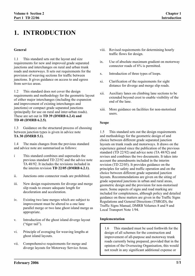

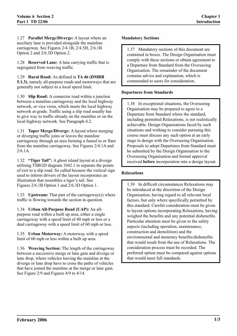


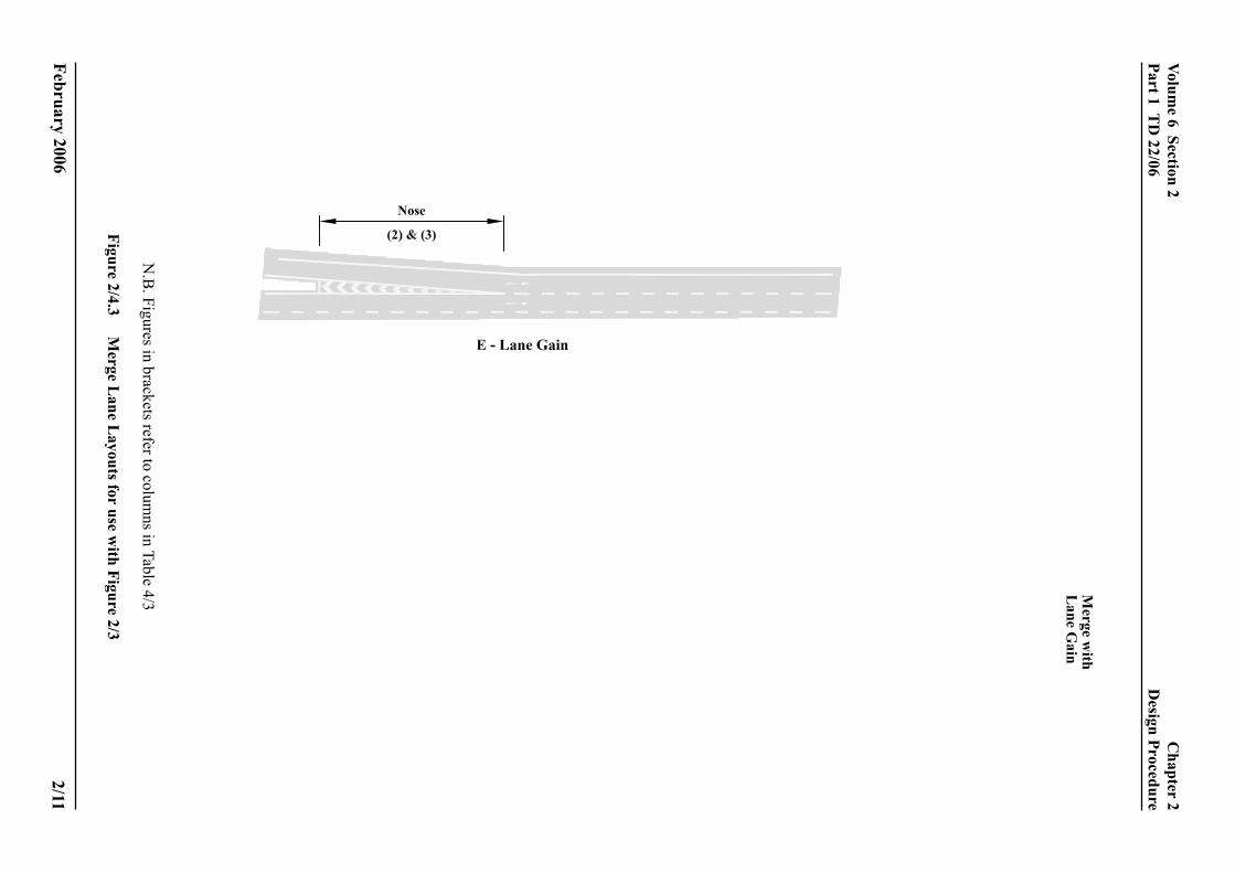


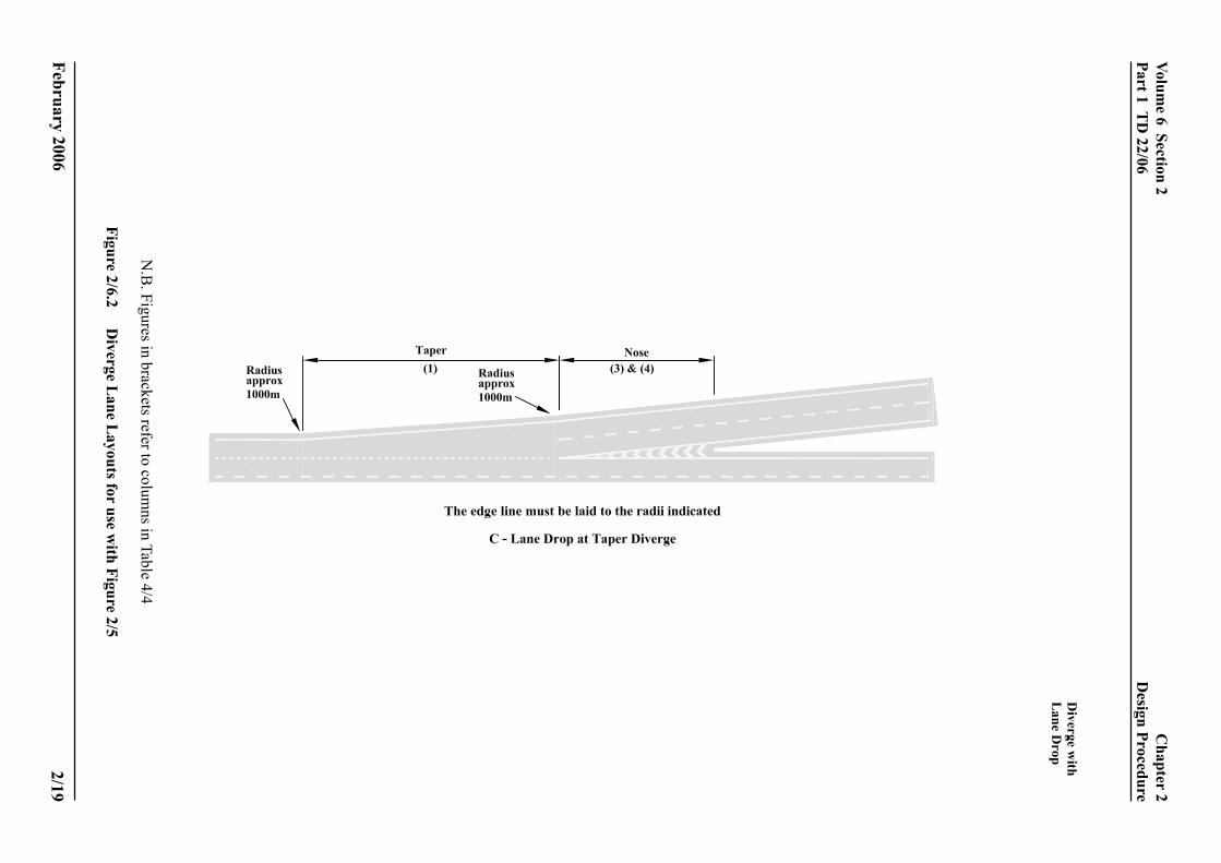

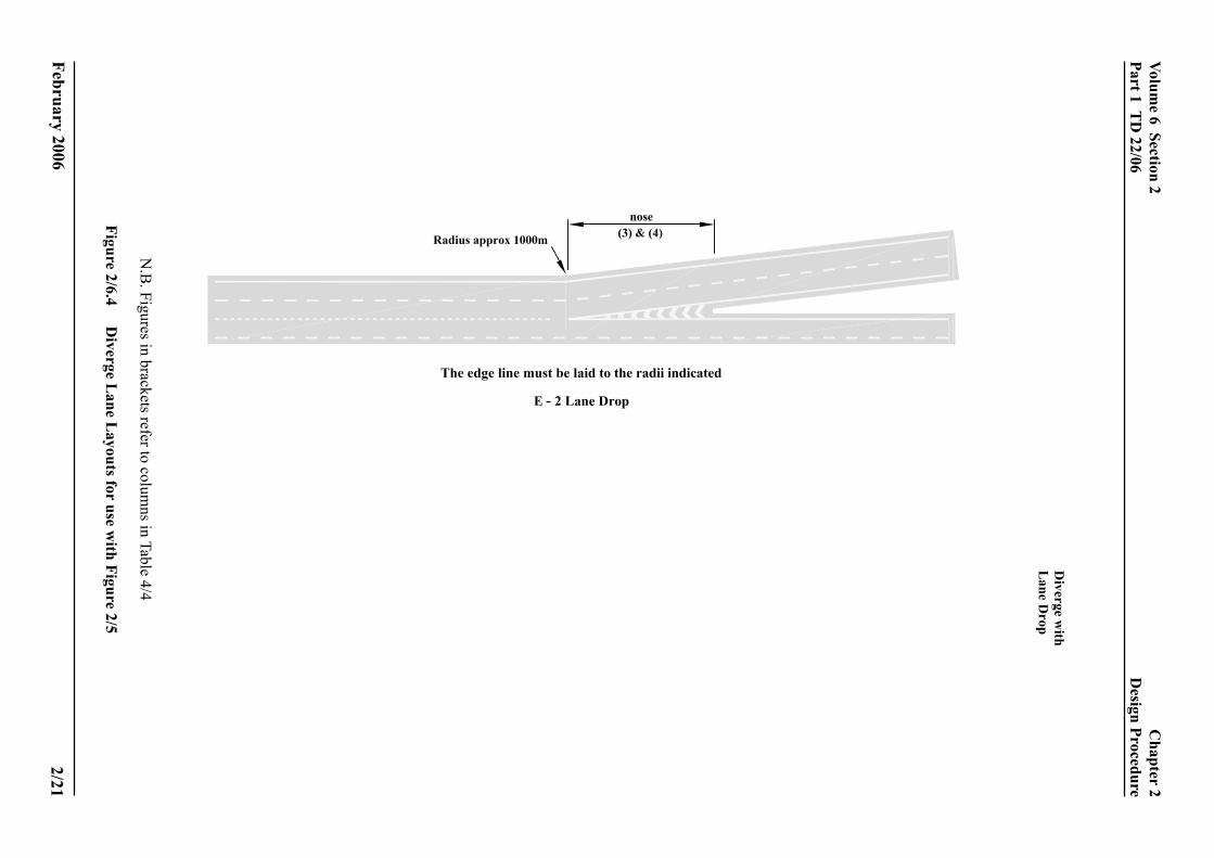


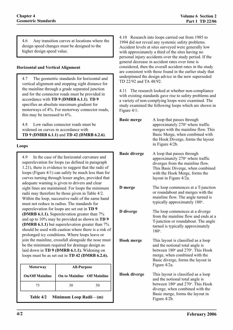


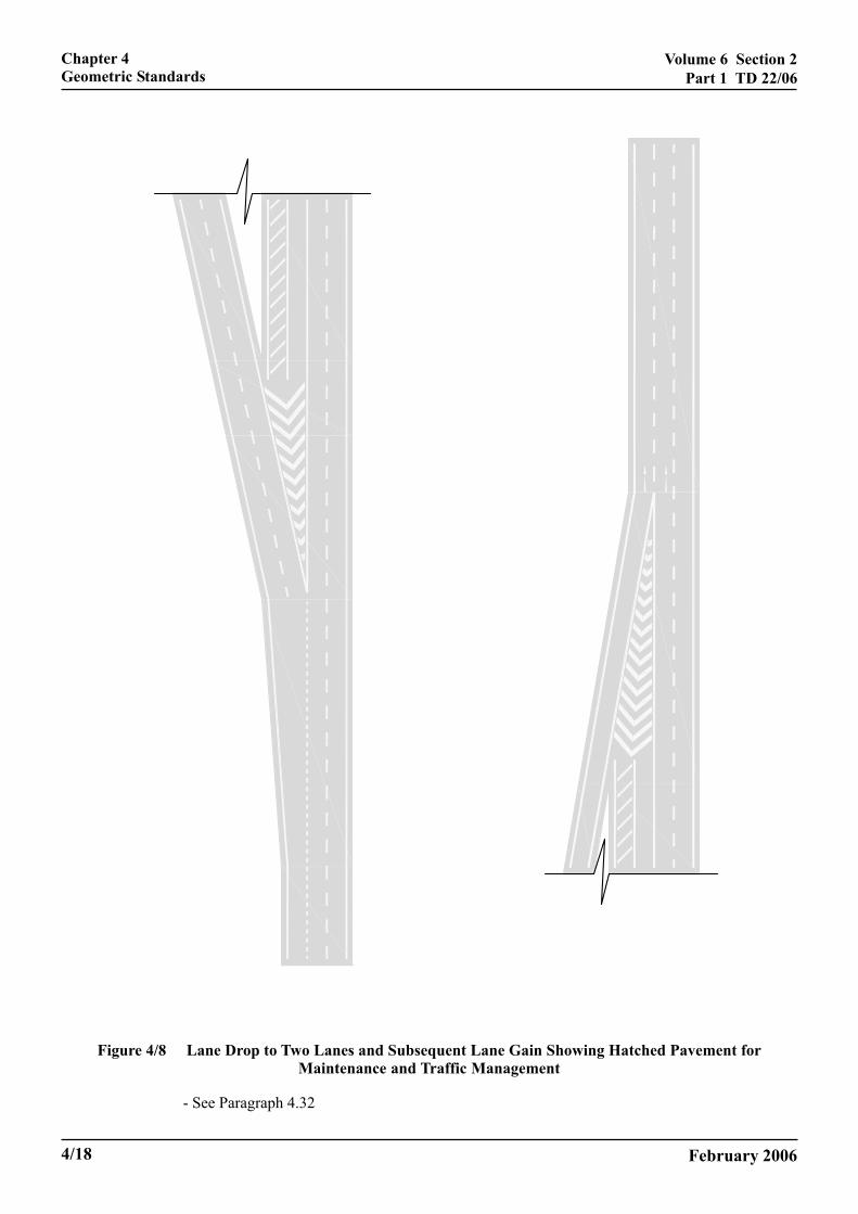


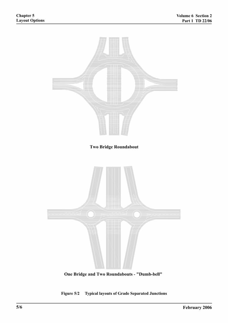


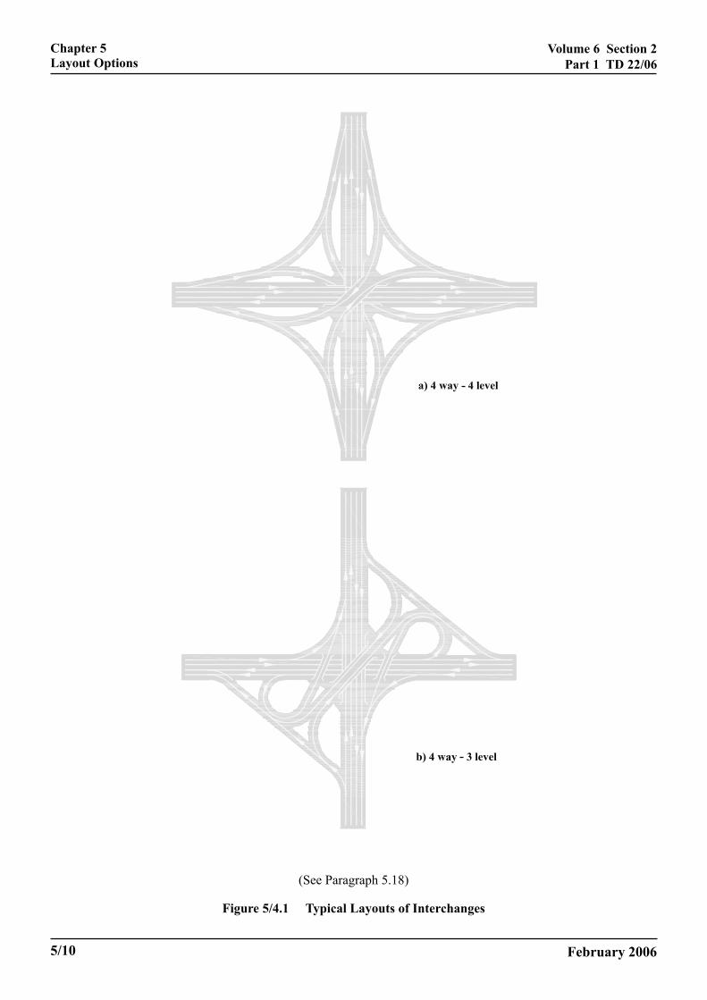


![Following Acute Encephalitis, Semliki Forest Virus is ... · specialized and regulated [1,2]; the resting CNS, is separated from the blood by the tight endothelial cell junctions](https://static.documents.pub/doc/80x56/5fc2e31a90e4ca5f24284858/following-acute-encephalitis-semliki-forest-virus-is-specialized-and-regulated.jpg)


