DMRC Electrical Standards & Design Wing DMES-T/0025 SPECIFICATIONS OF SUBSTATION AUTOMATION SYSTEM FOR RECEIVING SUBSTATION (RSS) Draft-1 Dated: 01 Feb 2018 DELHI METRO RAIL CORPORATION LIMITED DMRC ELECTRICAL STANDARDS & DESIGN WING (DESDW) SPECIFICATION NO. DMES- T0025/ DMRC-E-TR-SAS-01 SPECIFICATIONS OF SUBSTATION AUTOMATION SYSTEM FOR RECEIVING SUBSTATION (RSS) Issued on: Date Stage 01 ST Feb 2018 Draft - 1 DELHI METRO RAIL CORPORATION LTD. 7 th Floor, B-Wing, Metro Bhawan, Fire Brigade Lane,
SPECIFICATIONS OF SUBSTATION AUTOMATION SYSTEM FOR RECEIVING SUBSTATION (RSS)
Draft-1
Dated: 01 Feb 2018
1. DETAILED DESCRIPTION OF THE EQUIPMENT AND ITS APPLICATION
– SUBSTATION AUTOMATION SYSTEM FOR Receiving Sub Station (RSS) in DMRC
1.1. The Substation Automation System (SAS) shall be installed to control and monitor all the sub-station equipment from remote control centres (OCC) as well as from local control centre. The SAS shall contain the following main functional parts:
• Bay control Intelligence Electronic Devices (IED s) for control and monitoring.
• Bay Protection Intelligent Electronic device (IEDs) for Protection.
• Dedicated Bay Control Units and Bay Protection Units (BPU) shall be provided for each bay for Control and protection functionality on IEC-61850 standard. The Bay Control and Protection IEDs shall communicate on the IEC 61850 standard for Communication Networks and shall comply to the IEC61850-5 for communication data modeling, IEC61850-6 for Sub-Station Configuration, Description Language for communication and IEC61850-7-1 to 7-4 for Data Model and Services.
• Each of the IED/BCU/BPU provided shall be provided with its similar backup IED/BCU/BPU to ensure redundancy. This means for each IED/BCU/BPU the second hot standby IED/BCU/BPU should be provided which should automatically take over the system in the event of failure of main IED/BCU/BPU.
• Redundancy i.e Back up BCU/BPU/IED are to be quoted separately in BOQ as a separate item from main BCU/BPU/IED and provision to be kept for addition at a later stage, if required
• Station Human Machine Interface (HMI)
• Redundant managed switched Ethernet Local Area Network communication infrastructure with hot standby.
• Redundant Gateway for remote monitoring and control via industrial grade hardware (to OCC) compatible for IEC 60870-5-104 protocol or existing protocol. There will be at least 3 OCCs. Redundant Gateway for remote control and monitoring via industrial grade
hardware (to OCC and Backup Control Centre). The gateway should be able to communicate with OCC protocol. Each gateway shall have two communication ports for simultaneously reporting to two masters. The SAS system shall be connected to two control centers on a fiber optic network using two separate channels and will not be multidropped with other RTUs. The gateway shall have one spare port for connecting to a third master if required in future. The specific protocol to be implemented shall be advised to the successful bidder. It will be the bidder's responsibility to integrate his offered system with existing OCC system for exchange of desired data
• Redundant Gateway for remote monitoring and control via industrial grade hardware (to OCC), the gateway should be able to communicate with OCC on IEC 60870-5-101 and IEC 60870-5-104 protocol or existing protocol. It shall be the bidder’s responsibility to integrate his offered system with existing OCC system for exchange of desired data. The requirement of IO point shall be worked out by the bidder as per criterion enclosed as Appendix-II for data exchange with RLDCs.
• Remote HMI and work station along with necessary printers, if specified.
• Peripheral equipment like printers, display units, key boards, Mouse etc.
1.2. It shall enable local station control via a PC by means of human machine interface (HMI) and control software package, which shall contain an extensive range of supervisory control and data acquisition (SCADA) functions.
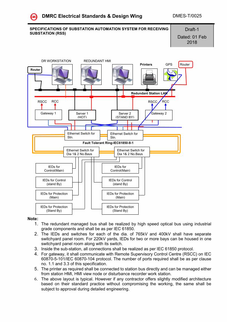
1.3. It shall include communication gateway, intelligent electronic devices (IED) for bay control and inter IED communication infrastructure. An architecture drawing for SAS is enclosed.
1.4. The communication gateway shall facilitate the information flow with remote control centres without looping Local Control Centre (LCC) I,e an independent gateway shall be available. The bay level intelligent electronic devices (IED) for protection and control shall provide the direct connection to the switchgear without the need of interposing components and perform control, protection, and monitoring functions.
SPECIFICATIONS OF SUBSTATION AUTOMATION SYSTEM FOR RECEIVING SUBSTATION (RSS)
Draft-1
Dated: 01 Feb 2018
1.5. The Sub-station Automation system being offered shall generally confirm to provision of IEC
62351, IEEE1686 and NERC CIP (all applicable part such as CIP 003, CIP-005, and CIP-007) for cyber security.
2. GOVERNING SPECIFICATIONS
2.1 STANDARDS The SAS shall satisfy the following requirements and shall also comply with standards in force when the inverters are manufactured, particularly as mentioned in the following table (Unless otherwise stipulated in the specifications, the latest version of the following Standards shall be applicable): -
Standard # Description
IEC 62351 Information Security for Power Control Systems
IEC 60870-5-104 Redundant Gateway for remote monitoring and control via
industrial grade hardware (to OCC)
2.2 ABBREVIATIONS
• IEC – International Electro technical Council
• HMI – Human Machine Interface
• RSS – Receiving Sub Station
• IED - Intelligent Electronic Devices
3. TECHNICAL REQUIREMENTS
3.1 GENERAL SYSTEM DESIGN
The Substation Automation System (SAS) shall be suitable for operation and monitoring of the complete substation including future extensions as given by the Employer.
The systems shall be of the state-of-the art suitable for operation under electrical environment present in Extra high voltage substations, follow the latest engineering practice, ensure long-term compatibility requirements and continuity of equipment supply and the safety of the operating staff.
The offered SAS shall support remote control and monitoring from Remote Control centers via gateways.
The system shall be designed such that personnel without any background knowledge in Microprocessor-based technology are able to operate the system. The operator interface shall be intuitive such that operating personnel shall be able to operate the system easily after having received some basic training.
The system shall incorporate the control, monitoring and protection functions specified, self-monitoring, signaling and testing facilities, measuring as well as memory functions, event recording and evaluation of disturbance records. It shall also have provisions for inhibiting control on any or all devices for purpose of maintenance. The devices under maintenance shall be provided with tags which shall include provision for entering text (256 characters).
SPECIFICATIONS OF SUBSTATION AUTOMATION SYSTEM FOR RECEIVING SUBSTATION (RSS)
Draft-1
Dated: 01 Feb 2018
Maintenance, modification or extension of components may not cause a shutdown of the whole substation automation system. Self-monitoring of components, modules and communication shall be incorporated to increase the availability and the reliability of the equipment and minimize maintenance.
IP addressing of the system shall be as per the IP plan prepared in consultation with by the Employer.
The system shall be remotely accessed for collection of disturbance records disturbance records and hence shall be provided with a firewall/router to comply at least with the requirements of CIP-005, CIP-007 (Critical infrastructure protection) standard as per NERC (North American Electric Reliability Council).
Bidder shall offer the Bay level unit (a bay comprises of one circuit breaker and associated disconnector, earth switches and instrument transformer), bay mimic along with relay and protection panels and PLCC panels (described in other sections of technical specifications) housed in air-conditioned Switchyard Panel Room suitably located in switchyard or any other air-conditioned relay room specified by the Employer and Station HMI in Control Room building for overall optimization in respect of cabling and control room building.
3.2 SYSTEM ARCHITECTURE
The SAS shall be based on a decentralized architecture and on a concept of bay-oriented, distributed intelligence.
Functions shall be decentralized, object-oriented and located as close as possible to the process.
The main process information of the station shall be stored in distributed databases. The typical SAS architecture shall be structured in two levels, i.e. in a station and a bay level.
At bay level, the IEDs shall provide all bay level functions regarding control, monitoring and protection, inputs for status indication and outputs for commands. The IEDs should be directly connected to the switchgear without any need for additional interposition or transducers.
All the numerical IEDs must be fully IEC 61850 compliant and must have the following features.
o Have peer-to-peer communication using GOOSE messages (IEC 61850) for interlocking.
o Should be interoperable with third party IEC 61850 compliant devices o Should generate XML file for integration/engineering with vendor independent
SCADA systems. o Should be directly connected to the inter bay bus on IEC 61850 without the use of
any gateways. Connections of bay protection IEDs to the IEC 61850 bus through the bay control units is not acceptable.
Each bay control IED shall be independent from each other and its functioning shall not be affected by any fault occurring in any of the other bay control units of the station.
The data exchange between the electronic devices on bay and station level shall take place via the communication infrastructure. This shall be realized using fiber-optic cables, thereby guaranteeing disturbance free communication. The fiber optic cables shall be run in GI conduit pipes. Data exchange is to be realized using IEC 61850 protocol with a redundant managed switched Ethernet communication infrastructure
SPECIFICATIONS OF SUBSTATION AUTOMATION SYSTEM FOR RECEIVING SUBSTATION (RSS)
Draft-1
Dated: 01 Feb 2018
The communication shall be made in fault tolerant ring, excluding the links between individual bay IEDs to switch wherein the redundant connections are not envisaged, such that failure of one set of fiber shall not affect the normal operation of the SAS. However failure of fiber shall be alarmed in SAS. Each fiber optic cable shall have four (4) spare fibers
At station level, the entire station shall be controlled and supervised from the station HMI. It shall also be possible to control and monitor the bay from the bay level equipment at all times.
Clear control priorities shall prevent operation of a single switch at the same time from more than one of the various control levels, i.e. OCC, station HMI, bay level or apparatus level. The priority shall always be on the lowest enabled control level.
The station level contains the station-oriented functions, which cannot be realized at bay level, e.g. alarm list or event list related to the entire substation, gateway for the communication with remote control centers.
The GPS time synchronizing signal (as specified in the section relay & protection) for the synchronization of the entire system shall be provided.
The SAS shall contain the functional parts as described in para 1.2 above.
3.3 FUNCTIONAL REQUIREMENTS
The high-voltage apparatus within the station shall be operated from different places:
➢ Remote / Operation control centers
➢ Station HMI.
➢ Local Bay controller IED (in the bays)
➢ Apparatus level
Operation shall be possible by only one operator at a time.
The operation shall depend on the conditions of other functions, such as interlocking, synchro-check, control-inhibit tags etc. (see description in ”Bay level control functions”).
3.3.1 SELECT-BEFORE-EXECUTE
For security reasons the command is always to be given in two stages: selection of the object and command for operation under all mode of operation except emergency operation. Final execution shall take place only when selection and command are actuated.
3.3.2 COMMAND SUPERVISION
Bay/station interlocking and blocking
Software Interlocking is to be provided to ensure that inadvertent incorrect operation of switchgear causing damage and accidents in case of false operation does not take place.
In addition to software interlocking hardwired interlocking are to be provided for:
(a) Bus Earth switch Interlocking
(b) Transfer Bus interlocking (if applicable)
(c) Any other interlocking decided in consultation with Employer.
It shall be a simple layout, easy to test and simple to handle when upgrading the station with future bays. For software interlocking the bidder shall describe the scenario while an IED of another bay is switched off or fails.
SPECIFICATIONS OF SUBSTATION AUTOMATION SYSTEM FOR RECEIVING SUBSTATION (RSS)
Draft-1
Dated: 01 Feb 2018
A software interlock override function shall be provided which can be enabled to bypass the interlocking function.
3.3.3 RUN TIME COMMAND CANCELLATION
Command execution timer (configurable) must be available for each control level connection. If the control action is not completed within a specified time, the command should get cancelled and an alarm shall be generated to indicate the failure of command.
3.3.4 SELF-SUPERVISION
Continuous self-supervision function with self-diagnostic feature shall be included. The redundant components such as servers, gateway shall monitor each other for availability and the active device shall takeover all the functions of the failed device. This failover shall happen within 30 seconds. The events occurring when a server is in failed state shall be synchronized from the active server.
3.3.5 USER CONFIGURATION
The monitoring, controlling and configuration of all input and output logical signals and binary inputs and relay outputs for all built-in functions and signals shall be possible both locally and remotely.
It shall also be possible to interconnect and derive input and output signals, logic functions, using built-In functions, complex voltage and currents, additional logics (AND-gates, OR gates and timers). (Multi-activation of these additional functions should be possible) with provision of activation of Disturbance record.
The Functional requirement shall be divided into following levels:
(a) Bay (a bay comprises of one circuit breaker and associated disconnector, earth switches and instrument transformer) level functions
(b) System level functions
3.4 Bay level functions
In a decentralized architecture the functionality shall be as close to the process as possible. In this respect, the following functions can be allocated at bay level:
• Bay control functions including data collection functionality in bay control/protection unit.
• Bay protection functions
Separate IEDs shall be provided for bay control function and bay protection function.
3.4.1 Bay control functions
3.4.1.1 Overview
Functions
▪ Control mode selection ▪ Select-before-execute principle ▪ Command supervision:
o Interlocking and blocking o Double command
▪ Synchro check, voltage selection ▪ Run Time Command cancellation
SPECIFICATIONS OF SUBSTATION AUTOMATION SYSTEM FOR RECEIVING SUBSTATION (RSS)
Draft-1
Dated: 01 Feb 2018
▪ Transformer tap changer control (Raise and lower of tap ) (for power transformer bays) ▪ Transformer Master/follower selection ▪ Operation counters for circuit breakers and pumps ▪ Hydraulic pump/ Air compressor runtime supervision ▪ Operating pressure supervision through digital contacts only ▪ Breaker position indication per phase ▪ Alarm annunciation ▪ Measurement display ▪ Local HMI (local guided, emergency mode) ▪ Interface to the station HMI. ▪ Data storage for at least 200 events ▪ Auto-reclose mode selection (Non-Auto/ 1phase) ▪ Extension possibilities with additional I/0's inside the unit or via fiber optic
communication and process bus.
3.4.1.2 Control mode selection
Bay level Operation:
As soon as the operator receives the operation access at bay level the operation is normally performed via bay control IED. During normal operation bay control unit allows the safe operation of all switching devices via the bay control IED. The IEDs shall be equipped with sufficient number of output contacts capable of making and breaking current for circuit breaker closing and breaking coil currents. The Nos of DI/Dos shall be sufficient to analyze sequence of al event in event list as well as Disturbance records as required for fault diagnosis. The Binary variables shall be minimum of 10 in numbers and the selection in event list and DR to be made in consultation of Employer.
EMERGENCY Operation
It shall be possible to close or open the selected Circuit Breaker with ON or OFF push buttons even during the outage of bay IED.
REMOTE mode
Control authority in this mode is given to a higher level (Remote Control Centre/Station HMI) and the installation can be controlled only remotely. Control operation from lower levels shall not be possible in this operating mode.
3.4.1.3 Synchronism and energizing check
The synchronism and energizing check functions shall be bay-oriented and distributed to the bay control and/or protection devices. These features are:
➢ Settable voltage, phase angle, and frequency difference.
➢ Energizing for dead line - live bus, live line - dead bus or dead line – dead bus with no synchro-check function.
➢ Synchronizing between live line and live bus with synchro-check function
Voltage selection
The voltages relevant for the Synchro check functions are dependent on the station topology, i.e. on the positions of the circuit breakers and/or the isolators. The correct voltage for synchronizing and energizing is derived from the auxiliary switches of the circuit breakers,
SPECIFICATIONS OF SUBSTATION AUTOMATION SYSTEM FOR RECEIVING SUBSTATION (RSS)
Draft-1
Dated: 01 Feb 2018
the isolator, and earthing switch and shall be selected automatically by the bay control and protection IEDs.
3.4.1.4 Transformer tap changer control
Raise and lower operation of OLTC taps of transformer shall be facilitated through Bay controller IED.
3.4.1.5 Transformer Master/Follower selection
In case of multiple transformer banks, Master/Follower selection shall be facilitated through bay controller IED. This selection shall be done through a DO contact from bay control unit.
3.4.1.6 Auto-reclose mode selection
Auto –reclose mode selection for each of the Circuit breaker shall be facilitated through bay controller IED.
3.4.1.7 Protection transfer switch control (As applicable)
Based on selection of isolator for double main and transfer switching scheme for the switchyard, the protection shall be transferred automatically with an alarm indication that protection is successfully transferred.
3.4.2 Bay protection functions
3.4.2.1 General
The protection functions are independent of bay control function. The protection shall be provided by separate protection IEDs (numerical relays) and other protection devices as per section Relay & Protection. The protection shall be in HOT-HOT configuration.
IEDs, shall be connected to the communication infrastructure for data sharing and meet the real-time communication requirements for automatic functions. The data presentation and the configuration of the various IEDs shall be compatible with the overall system communication and data exchange requirements.
Event and disturbance recording function
Each IED should contain an event recorder capable of storing at least 200 time-tagged events. The disturbance recorder function shall be as per detailed in section C&R
3.4.2.2 Bay Monitoring Function:
Analogue inputs for voltage and current measurements shall be connected directly to the voltage transformers (VT) and the current transformers (CT) without intermediate transducers. The values of active power (W), reactive power (VAR), frequency (Hz), and the rms values for voltage (U) and current (I) shall be calculated in the Bay control/protection unit.
3.5 System level functions
3.5.1 Status supervision
The position of each switchgear, e.g. circuit breaker, isolator, earthing switch, transformer tap changer etc., shall be supervised continuously. Every detected change of position shall be immediately displayed in the single-line diagram on the station HMI screen, recorded in the event list, and a hard copy printout shall be produced. Alarms shall be initiated in the case of spontaneous position changes.
SPECIFICATIONS OF SUBSTATION AUTOMATION SYSTEM FOR RECEIVING SUBSTATION (RSS)
Draft-1
Dated: 01 Feb 2018
The switchgear positions shall be indicated by two auxiliary switches, normally closed (NC) and normally open (NO), which shall give ambivalent signals. An alarm shall be initiated if these position indications are inconsistent or if the time required for operating mechanism to change position exceeds a predefined limit.
The SAS shall also monitor the status of sub-station auxiliaries. The status and control of auxiliaries shall be done through separate one or more IED and all alarm and analogue values shall be monitored and recoded through this IED.
3.5.2 Measurements
The analogue values acquired/calculated in bay control/protection unit shall be displayed locally on the station HMI and in the control centre. The abnormal values must be discarded. The analogue values shall be updated every 2 seconds and the same shall be demonstrated during FAT of the system.
Threshold limit values shall be selectable for alarm indications.
3.5.3 Event and alarm handling
Events and alarms are generated either by the switchgear, by the control IEDs, or by the station level unit. They shall be recorded in an event list in the station HMI. Alarms shall be recorded in a separate alarm list and appear on the screen. All, or a freely selectable group of events and alarms shall also be printed out on an event printer. The alarms and events shall be time-tagged with a time resolution of 1 ms. The tentative list for various feeders and systems are enclosed as Annexure-I
3.5.4 Station HMI
3.5.4.1 Substation HMI Operation:
On the HMI the object has to be selected first. In case of blocking or interlocking conditions are not met, the selection shall not be possible and an appropriate alarm annunciation with pop up of unfulfilled conditions shall occur. If a selection is valid the position indication will show the possible direction, and the appropriate control execution button shall be pressed in order to close or open the corresponding object.
Control operation from other places (e.g. OCCs) shall not be possible in this operating mode.
3.5.4.2 Presentation and dialogues
General
The operator station HMI shall be a redundant with hot standby and shall provide basic functions for supervision and control of the substation. The operator shall give commands to the switchgear on the screen via mouse clicks.
The HMI shall give the operator access to alarms and events displayed on the screen. Aside from these lists on the screen, there shall be a printout of alarms or events in an event log.
An acoustic alarm shall indicate abnormalities, and all unacknowledged alarms shall be accessible from any screen selected by the operator.
The following standard pictures shall be available from the HMI:
➢ Single-line diagram showing the switchgear status and measured values
➢ Control dialogues with interlocking or blocking information details. This control dialogue shall tell the operator whether the device operation is permitted or blocked and also show the Interlocking logic with status.
SPECIFICATIONS OF SUBSTATION AUTOMATION SYSTEM FOR RECEIVING SUBSTATION (RSS)
Draft-1
Dated: 01 Feb 2018
➢ Measurement dialogues
➢ Alarm list, station / bay-oriented
➢ Event list, station / bay-oriented
➢ System status
3.5.4.3 HMI design principles
Consistent design principles shall be adopted with the HMI concerning labels, colours, dialogues and fonts. Non-valid selections shall be dimmed out.
The object status shall be indicated using different status colours for:
➢ Selected object under command
➢ Selected on the screen
➢ Not updated, obsolete values, not in use or not sampled
➢ Alarm or faulty state
➢ Warning or blocked
➢ Update blocked or manually updated
➢ Control blocked
➢ Normal state
➢ Energized or deenergized state (based on substation topology)
3.5.4.4 Process status displays and command procedures
The process status of the substation in terms of actual values of currents, voltages, frequency, active and reactive powers as well as the positions of circuit breakers, isolators and transformer tap-changers shall be displayed in the station single-line diagram.
In order to ensure a high degree of security against undesired operation, a "select-before-execute" command procedure shall be provided. After the "selection" of a switch, the operator shall be able to recognize the selected device on the screen, and all other switchgear shall be blocked. As communication between control center and device to be controlled is established, the operator shall be prompted to confirm the control action and only then final execute command shall be accepted. After the “execution” of the command the operated switching symbol shall flash until the switch has reached its new position.
The operator shall be in a position to execute a command only, if the switch is not blocked and if no interlocking condition is going to be violated. The interlocking statements shall be checked by the interlocking scheme implemented at bay and station level. In case of Blocking, Execute Command shall not be Highlighted.
After command execution the operator shall receive a confirmation that the new switching position has been reached or an indication that the switching procedure was unsuccessful with the indication of the reason for non-functioning.
3.5.4.5 System supervision & display
The SAS system shall be comprehensively self-monitored such that faults are immediately indicated to the operator, possibly before they develop into serious situations. Such faults are recorded as a faulty status in a system supervision display. This display shall cover the
SPECIFICATIONS OF SUBSTATION AUTOMATION SYSTEM FOR RECEIVING SUBSTATION (RSS)
Draft-1
Dated: 01 Feb 2018
status of the entire substation including all switchgear, IEDs, communication infrastructure and remote communication links, and printers at the station level, etc.
3.5.4.6 Event list
The event list shall contain events that are important for the control and monitoring of the substation.
The event and associated time (with1 ms resolution) of its occurrence has to be displayed for each event.
The operator shall be able to call up the chronological event list on the monitor at any time for the whole substation or sections of it.
A printout of each display shall be possible on the hard copy printer.
The events shall be registered in a chronological event list in which the type of event and its time of occurrence are specified. It shall be possible to store all events in the computer for at least one month. The information shall be obtainable also from a printed event log.
The chronological event list shall contain:
➢ Position changes of circuit breakers, isolators and earthing devices
➢ Indication of protective relay operations
➢ Fault signals from the switchgear
➢ Indication when analogue measured values exceed upper and lower limits. Suitable provision shall be made in the system to define two level of alarm on either side of the value or which shall be user defined for each measurands.
➢ Loss of communication.
➢ User actions (control/Tag placement/manual update) with USER identity
➢ System messages (Operator logging info, System supervision and device monitoring, failure of supervisory control etc.)
Filters for selection of a certain type or group of events shall be available. The filters shall be designed to enable viewing of events grouped per:
➢ Date and time
➢ Bay / Multi Bay / Effected Bays only
➢ Device
➢ Function e.g. trips, protection operations etc.
➢ Alarm class
3.5.4.7 Alarm list
Faults and errors occurring in the substation shall be listed in an alarm list and must be displayed in a flashing state along with an audible alarm. After acknowledgement of the alarm, it should appear in a steady (i.e. not flashing) state and the audible alarm shall stop. The alarm should disappear only if the alarm condition has physically cleared and the operator has reset the alarm with a reset command. The state of the alarms shall be shown in the alarm list (Unacknowledged and persistent, Unacknowledged and cleared, Acknowledged and persistent).
Filters for selection of a certain type or group of alarms shall be available as for events.
SPECIFICATIONS OF SUBSTATION AUTOMATION SYSTEM FOR RECEIVING SUBSTATION (RSS)
Draft-1
Dated: 01 Feb 2018
3.5.4.8 Object picture
When selecting an object such as a circuit breaker or isolator in the single-line diagram, the associated bay picture shall be presented first. In the selected object picture, all attributes like
➢ Type of blocking/Control inhibit Tag
➢ Authority
➢ Local / remote control mode
➢ OCC / SAS control
➢ Errors
➢ etc.,
shall be displayed. Control inhibit tags shall also be displayed on the main picture.
3.5.4.9 Control dialogues
The operator shall give commands to the system by means of mouse click located on the single-line diagram. Data entry is performed with the keyboard. Dedicated control dialogues for controlling at least the following devices shall be available:
The BCU shall be configured to continuously monitor the CVT cores. The values from each of the phases shall be compared and any difference more than a specified value shall generate an alarm.
3.5.4.11 Station level monitoring All the feeder RMS values of MW/MVAR shall be summed up at the Station level. This sum shall normally be equal to zero and any difference greater than a specified value which shall be user programmable shall be alarmed. This alarm shall also be sent to the OCCs as an event.
3.5.5 User-authority levels
It shall be possible to restrict activation of the process pictures of each object (bays, apparatus...) within a certain user authorization group. Each user shall then be given access rights to each group of objects, e.g.:
➢ Display only
➢ Normal operation (e.g. open/close of switchgear)
SPECIFICATIONS OF SUBSTATION AUTOMATION SYSTEM FOR RECEIVING SUBSTATION (RSS)
Draft-1
Dated: 01 Feb 2018
➢ No engineering allowed
➢ Engineering/configuration allowed
➢ Entire system management allowed
The access rights shall be defined by passwords assigned during the log-in procedure. Only the system administrator shall be able to add/remove users and change access rights.
3.5.6 Reports
The reports shall provide time-related follow-ups of measured and calculated values. The data displayed shall comprise:
➢ Trend reports:
• Day (mean, peak)
• Month (mean, peak)
• Semi-annual (mean, peak)
• Year (mean, peak)
➢ Historical reports of selected analogue Values:
• Day (at 15 minutes interval)
• Week
• Month
• Year
It shall be possible to select stored values from the database in the process display on-line. Scrolling between e.g. days shall be possible. Unsure values shall be indicated. It shall be possible to select the time period for which the specific data are stored in the memory.
Following printouts shall be available from the printer and shall be printed on demand:
i. Daily voltage and frequency curves depicting time on X-axis and the appropriate parameters on the Y-axis. The time duration of the curve is 24 hours.
ii. Weekly trend curves for real and derived analogue values.
iii. Printouts of the maximum and minimum values and frequency of occurrence and duration
of maximum and minimum values for each analogue parameter for each circuit in 24 hr period.
iv. Provision shall be made for logging information about breaker status like number of
operation with date and time indications along with the current vale it interrupts (in both condition i.e. manual opening and fault tripping)
v. Equipment operation details shift wise and during 24 hours.
vi. Printout on adjustable time period as well as on demand for MW, MVAR, Current, Voltage
on each feeder and transformer as well as Tap Positions, temperature and status of pumps and fans for transformers.
vii. Printout on adjustable time period as well as on demand system frequency and average
SPECIFICATIONS OF SUBSTATION AUTOMATION SYSTEM FOR RECEIVING SUBSTATION (RSS)
Draft-1
Dated: 01 Feb 2018
frequency.
viii. Reports in specified formats which shall be handed over to successful bidder. The bidder has to develop these reports. The reports are limited to the formats for which data is available in the SAS database.
All the utilities/tools used for building a report shall be provided with the system so that the Employer is able to build new reports. The tools shall be user friendly with ‘drag & drop’ or ‘menu based selection’ features and shall not require any knowledge of programming.
The reports utility shall be configured such that reports requiring long duration data (yearly) shall not take more than 2 minutes and does not impact the other applications running in the system.
3.5.7 Trend display (historical data)
It shall be possible to illustrate all types of process data as trends - input and output data, binary and analogue data. The trends shall be displayed in graphical form as column or curve diagrams with a maximum of 10 trends per screen. Adjustable time span and scaling ranges must be provided.
It shall be possible to change the type of value logging (direct, mean, sum, or difference) on-line in the window. It shall also be possible to change the update intervals on-line in the picture as well as the selection of threshold values for alarming purposes.
3.5.8 Automatic disturbance file transfer
All recorded data from the IEDs with integrated disturbance recorder as well as dedicated disturbance recording systems shall be automatically uploaded (event triggered or once per day in case no event during the day) to a dedicated computer and be stored on the hard disc in specified folders.
3.5.9 Disturbance analysis
The PC-based work station shall have necessary software to evaluate all the required information for proper fault analysis.
3.5.10 IED parameter setting
It shall be possible to access all protection and control IEDs for reading the parameters (settings) from the station HMI or from a dedicated monitoring computer. The setting of parameters or the activation of parameter sets shall only be allowed after entering a password.
3.5.11 Automatic sequences
The available automatic sequences in the system should be listed and described, (e.g. sequences related to the bus transfer in a GIS). It must be possible to initiate pre-defined automatic sequences by the operator and also define new automatic sequences. The automatic sequencing is required to be developed at SCADA level.
3.6 Gateway
3.6.1 Communication Interface
The Substation Automation System shall have the capability to support simultaneous communications with multiple independent remote master stations,
The Substation Automation System shall have communication ports on each gateway as
SPECIFICATIONS OF SUBSTATION AUTOMATION SYSTEM FOR RECEIVING SUBSTATION (RSS)
Draft-1
Dated: 01 Feb 2018
(a) Three ports for Remote Control Centers on Secure IEC 60870-5-104 protocol
or Existing protocol.
The communication interface to the SAS shall allow scanning and control of defined points within the substation automation system independently for each control centre. The substation automation system shall simultaneously respond to independent scans and commands from employer's control centres (OCCs & RSCC). The substation automation system shall support the use of a different communication data exchange rate (bits per second), scanning cycle, and/or communication protocol to each remote control centre. Also, each control centre’s data scan and control commands may be different for different data points within the substation automation system's database. The Gateway shall identify the actions performed by the each of the remote masters individually and log it in its database. The logs for last 30 days shall be stored and accessible at the Station HMI.
3.6.2 Remote Control Centre Communication Interface
Employer will supply communication channels between the Substation Automation System and the remote control center. The communication channels provided by Employer will consist either of power line carrier, microwave, optical fibre, VSAT or leased line, the details of which shall be provided during detailed Engineering.
3.6.3 Interface equipment
The Contractor shall provide interface equipment for communicating between Substation Automation system and Remote-control centers and between Substation Automation system. However, the communication channels available for this purpose are specified in section project. The communication interface with the OCCs is an Ethernet interface. In case of PLCC communication any modem supplied shall not require manual equalization and shall include self-test features such as manual mark/space keying, analogue loop-back, and digital loop-back. The modems shall provide for convenient adjustment of output level and receive sensitivity. The modem should be standalone complete in all respects including power supply to interface the SAS with communication channel. The configuration of tones and speed shall be programmable and maintained in non-volatile memory in the modem. All necessary hardware and software shall also be in the scope of bidder except the communication link along with communication equipment between substation control room and Remote-Control Centre.
3.6.4 Communication Protocol
The communication protocol for gateway to control center must be open protocol and shall support IEC 60870-5-101 and IEC 60870-5-104 and IEC 61850 for all levels of communication for sub-station automation such as Bay to station HMI, bay to bay etc. based on requirement. The protocol shall support the features such as Report by exception; Periodic reporting so that the data update times at the OCC/RSCC can be optimized.
3.7 System hardware:
3.7.1 REDUNDANT STATION HMI, REMOTE HMI AND DISTURBANCE RECORDER WORK STATION:
SPECIFICATIONS OF SUBSTATION AUTOMATION SYSTEM FOR RECEIVING SUBSTATION (RSS)
Draft-1
Dated: 01 Feb 2018
The contractor shall provide redundant station HMI in hot standby mode. The servers used in these work stations shall be of industrial grade.
It shall be capable to perform all functions for entire substation including future requirements as indicated in the SLD. It shall use industrial grade components. Processor and RAM shall be selected in such a manner that during normal operation not more than 30% capacity of processing and memory are used. Supplier shall demonstrate these features. The capacity of hard disk shall be selected such that the following requirement should occupy less than 50% of disk space: 1. Storage of all analogue data (at 15 Minutes interval)and digital data including alarm ,
event for two years and trend data for thirty(30) days, 2. Storage of all necessary software, 3. 20GB space for EMPLOYER'S use.
Supplier shall demonstrate that the capacity of hard disk is sufficient to meet the above requirement.
3.7.2 HMI (HUMAN MACHINE INTERFACE)
The VDU shall show overview diagrams (Single Line Diagrams) and complete details of the switchgear with a colour display. All event and alarm annunciation shall be selectable in the form of lists. Operation shall be by a user friendly function keyboard and a cursor positioning device. The user interface shall be based on WINDOWS concepts with graphics & facility for panning, scrolling, zooming, decluttering etc.
3.7.3 VISUAL DISPLAY UNITS/TFT'S (THIN FILM TECHNOLOGY)
The display units shall have high resolution and reflection protected picture screen. High stability of the picture geometry shall be ensured. The screen shall be at least 21" diagonally in size and capable of colour graphic displays. The display shall accommodate resolution of 1280 x 1024 pixels. An Ergonomic study shall be done to decide the most suitable size of Screen , however the screen shall not be less than 21”.
3.7.4 PRINTER
It shall be robust & suitable for operation with a minimum of 132 characters per line. The printing operation shall be quiet with a noise level of less than 45 dB suitable for location in the control room. Printer shall accept and print all ASCII characters via master control computer unit interface.
The printer shall have in built testing facility. Failure of the printer shall be indicated in the Station HMI. The printer shall have an off-line mode selector switch to enable safe maintenance. The maintenance should be simple with provisions for ease of change of print head, ribbon changing, paper insertion etc.
All reports and graphics prints shall be printed on laser printer. One dot matrix printer shall be exclusively used for hourly log printing. All printers shall be continuously online.
3.7.5 MASS STORAGE UNIT
The mass storage unit shall be built-in to the Station HMI. All operational measured values, and indications shall be stored in a mass-storage unit in form of DVD RW. The unit should support at least Read (48X), Write(24X), and Re-Write (10X) operations, with Multi-Session
SPECIFICATIONS OF SUBSTATION AUTOMATION SYSTEM FOR RECEIVING SUBSTATION (RSS)
Draft-1
Dated: 01 Feb 2018
capability. It should support ISO9660, Rockridge and Joliet Filesystems. It should support formatting and use under the operating system provided for Station HMI. The monthly back up of data shall be taken on disc. The facility of back up of data shall be inherent in the software.
3.7.6 SWITCHED ETHERNET COMMUNICATION INFRASTRUCTURE:
The bidder shall provide the redundant switched optical Ethernet communication infrastructure for SAS. One switch shall be provided to connect all IEDs in one diameter of each 765 and 400kV yard and for two bays of 220kV yard to communication infrastructure. Each switch shall have at least two spare ports for connecting bay level IEDs and one spare port for connecting station bus. Auxiliary supply to Switch shall be HOT-HOT mode.
3.7.7 FIREWALL AND ROUTER
There shall be two sets of Firewall and Routers which shall be connected to a LAN. This LAN shall be different than the IEC 61850 LAN.The substation firewall and router shall be suitable for the substation environment and shall comply with the requirements for IEC 61850-3. The substation firewall shall have the following features:
• IP firewall features such as Address/port inspection and filtering
• Shall be stateful firewall
• 4 Ethernet switches 10/100 Mbps
• Shall support IPv4 and IPv6
• Shall have IP sec/VPN with 3DES/AES encryption
• Shall have NAT
• Shall have syslog capability
• Shall be NERC compliant
• Shall have hot- standby operation with similar router The substation routers shall have the following features
• Routing protocols such as OSPF and support for IPv4 and IPv6
• Ethernet interfaces of 10/100 Mbps
• 2 E1 interfaces
• Hot standby operation with a similar router
• Support IEEE 802.3u, 802.1p, 802.1Q, 802.1d, 802.1w,
• Traffic prioritization for routed IP flows/ports
The substation firewall and router can be a single device.
3.8 Bay level unit or Bay control unit (BCU)
3.8.1 GENERAL
• Bay Control Unit (BCU) shall be provided for each Bays (a bay comprises of one circuit breaker and associated disconnector, earth switches and instrument transformer, Number of bays shall be as per Section-Project) for control and monitoring of the bay equipments. Separate BCU (as per section-project) shall be provided for the monitoring of substation auxiliaries.
• BCU shall be capable of integration with the substation automation system based on IEC61850
SPECIFICATIONS OF SUBSTATION AUTOMATION SYSTEM FOR RECEIVING SUBSTATION (RSS)
Draft-1
Dated: 01 Feb 2018
• The BCUs shall be of modular in construction with adequate capacity for the estimated hardwired Inputs & Outputs plus 20% spare capacity. Requirement for external IO modules shall be avoided as far as possible.
• BCUs shall have redundant DC Power Supply or with automatic changeover scheme, to be fed from the two Station 110V DC systems. Each power supply shall be supervised separately and alarmed.
• Each BCU shall be equipped with Local HMI facilities, enabling control of each particular bay from BCU whenever required. The Local HMI facilities preferably shall be accomplished by means of Graphical LCD display embedded into the front panel of the BCU. Display will show simplify SLD diagram (with device identification number) showing status of bay switching equipment (such as circuit breaker, isolators, earth switches) and enabling issuance of switching controls. Other display type will be multiple displays of analog values readings / reports, displays for controls other than switching, Alarm panel displays, Diagnostic/ on-line configuration displays etc.
• In the event of switchgear apparatus controls, the software-interlocking scheme should be applied based on hardwired analog/digital inputs. In the event of closing control for circuit breakers requiring checking of synchronization conditions, software synchro-check scheme should be applied as well. Auto-reclose functions mentioned elsewhere in the specification, if required, can also be applied.
3.8.2 DESIGN
• The bay unit shall use industrial grade components. The bay level unit, based on microprocessor technology, shall use numerical techniques for the calculation and evaluation of externally input analogue signals. They shall incorporate select-before-operate control principles as safety measures for operation via the HMI.
• They shall perform all bay related functions, such as control commands, bay interlocking, data acquisition, data storage, event recording and shall provide inputs for status indication and outputs for commands. They shall be directly connected to the switchgear. The bay unit shall acquire and process all data for the bay (Equipment status, fault indications, measured values, alarms etc.) and transmit these to the other devices in sub-station automation system. In addition, this shall receive the operation commands from station HMI and control centre.
• One no. Bay Control unit shall be provided for supervision and control of each 765, 400 and 220 kV bay (a bay comprises of one circuit breaker and associated disconnector, earth switches and instrument transformer). The Bay level unit shall be equipped with analogue and binary inputs/outputs for handling the control, status monitoring and analogue measurement functions. All bay level interlocks are to be incorporated in the Bay level unit so as to permit control from the Bay level unit/ local bay mimic panel, with all bay interlocks in place, during maintenance and commissioning or in case of contingencies when the Station HMI is out of service.
• The bay control unit to be provided for the bays shall be preferably installed in the CB relay panel/feeder protection panel for respective bay. Further in case of one and half breaker schemes, the BCU for Tie CB shall be provided in Tie CB relay panel. The tie CB relay panel shall also house the Ethernet switch(es) to be provided for the diameter. The bay control unit for future bay (if required as per section project) shall be installed in a separate panel.
SPECIFICATIONS OF SUBSTATION AUTOMATION SYSTEM FOR RECEIVING SUBSTATION (RSS)
Draft-1
Dated: 01 Feb 2018
• The Bay level unit shall meet the requirements for withstanding electromagnetic interference according to relevant parts of IEC 61850. Failure of any single component within the equipment shall neither cause unwanted operation nor lead to a complete system breakdown.
3.8.3 INPUT/OUTPUT (I/O) MODULES
• The I/O modules shall form a part of the bay level unit / Bay control unit and shall provide coupling to the substation equipment. The I/O modules shall acquire all switchgear information (i.e. data coming directly from the switchgear or from switchgear interlocking devices) and transmit commands for operation of the switchgear.
• It shall be suitable for analog inputs from secondary of instrument transformers.
• The BCU/IED shall be able to integrate at least 10 analog input channels as a minimum and digital input / output channel to meet the control & monitoring scheme requirement.
• Plant alarms and indications will be derived as digital input from volt free contacts. Equipment with two normal states, e.g. circuit breakers, isolators and earth switches shall be represented by two source contacts to provide a positive indication of state. Plant contacts shall change state to register the specified status change or alarm, and each input shall be configurable to register a positive input from either a closed or open contact, i.e. input signals may be either a normally open or a normally closed contact. Alarm contacts may be either fleeting or sustained inputs. Digital filtering to suppress plant contact bounce shall be provided for each input. Time tagging to a resolution of 1 ms shall be provided.
• The pulse counting inputs shall be provided as per scheme requirement. These input shall acquire and count impulses produced by “volt free” contacts, which can be either, normally open or normally closed. Pulse counting inputs shall be provided as either a separate input module or using digital inputs. These inputs shall meet the same requirements specified for digital inputs; additionally they shall be able to cater for pulse rates up to 10 per second.
• Where DC analogue measurement inputs are provided as per the scheme requirement, they shall be capable of accepting unipolar and bipolar current of range 0-10/4-20mA and -10 to +10 mA selected on channel basis, with over/under range detection. The accuracy of the ADC conversion shall be +0.1% or better of full scale.
• The command outputs shall be designed to provide select and execute outputs. The period of the command pulse shall be configurable between 0.1 second and 15 seconds on point basis. The command pulses shall reset immediately after the command is executed. Controls transmitted between the operator workstation of SAS / SCADA and the BCU shall comprise a select, check back & execute sequence (or other means of providing high message security).
The BCU supplied for substation automation system shall further meet the requirements mentioned elsewhere in the specification
3.9 Extendibility in future
Offered substation automation system shall be suitable for extension in future for additional bays. During such requirement, all the drawings and configurations, alarm/event list etc. displayed shall be designed in such a manner that its extension shall be easily performed by
SPECIFICATIONS OF SUBSTATION AUTOMATION SYSTEM FOR RECEIVING SUBSTATION (RSS)
Draft-1
Dated: 01 Feb 2018
the employer. During such event, normal operation of the existing substation shall be unaffected and system shall not require a shutdown. The contractor shall provide all necessary software tools along with source codes to perform addition of bays in future and complete integration with SAS by the user. These software tools shall be able to configure IED, add additional analogue variable, alarm list, event list, modify interlocking logics etc. for additional bays/equipment which shall be added in future. Following is to be ensured during initial supply of system:
• All the licenses for various components such as SCADA, servers, Gateways etc. shall be for complete system i.e. system as per single line diagram including both present and future scope. All the servers shall be capable of handling total system (present and future).
3.10 Software structure
The software package shall be structured according to the SAS architecture and strictly divided in various levels. Necessary firewall shall be provided at suitable points in software to protect the system. An extension of the station shall be possible with lowest possible efforts. Maintenance, modification or an extension of components of any feeder may not force a shut-down of the parts of the system which are not affected by the system adaptation.
3.10.1 STATION LEVEL SOFTWARE
3.10.1.1 Human-machine interface (HMI)
The base HMI software package for the operator station shall include the main SAS functions and it shall be independent of project specific hardware version and operating system. It shall further include tools for picture editing, engineering and system configuration. The system shall be easy to use, to maintain, and to adapt according to specific user requirements. Systems shall contain a library with standard functions and applications.
3.10.2 BAY LEVEL SOFTWARE
3.10.2.1 System software
The system software shall be structured in various levels. This software shall be placed in a non-volatile memory. The lowest level shall assure system performance and contain basic functions, which shall not be accessible by the application and maintenance engineer for modifications. The system shall support the generation of typical control macros and a process database for user specific data storage. In case of restoration of links after failure, the software along with hardware shall be capable of automatically synchronising with the remaining system without any manual interface. This shall be demonstrated by contractor during integrated system test.
3.10.2.2 Application software
In order to ensure robust quality and reliable software functions, the main part of the application software shall consist of standard software modules built as functional block elements. The functional blocks shall be documented and thoroughly tested. They form part of a library. The application software within the control/protection devices shall be programmed in a functional block language.
3.10.3 NETWORK MANAGEMENT SYSTEM:
The contractor shall provide network management system software for following management functions:
SPECIFICATIONS OF SUBSTATION AUTOMATION SYSTEM FOR RECEIVING SUBSTATION (RSS)
Draft-1
Dated: 01 Feb 2018
a. Configuration Management b. Fault Management c. Performance Monitoring
This system shall be used for management of communication devices and other IEDs in the system. This NMS can be loaded in DR work-station and shall be easy to use, user friendly and menu based. The NMS shall monitor all the devices in the SAS and report if there is any communication fault/problem in the monitored devices. The NMS shall a. Maintain performance, resource usage, and error statistics for all managed links and
devices and present this information via displays, periodic reports and on demand reports.
b. Maintain a graphical display of SAS connectivity and device status. c. Issue alarms when error conditions occur d. Provide facility to add and delete addresses and links
3.10.4 OPERATING SYSTEM
The Operating system of the Servers, HMIs and Gateways shall be hardened as per the following guidelines to reduce its vulnerability to cyber-attacks.
1) Secure Build Strategy Packages unnecessary for system operation are not to be installed during the initial build of the servers and workstations, reducing the amount of post-build hardening required. Any package that must be installed but is not required to be actively running have to be disabled. The software to be removed and/or disabled includes, but is not limited to:
• Games
• Messaging services
• Servers or clients for unused Internet services
• Software compilers (except where required, i.e. development platform)
• Unused networking and communication protocols
• Unused operating system features
• free utilities delivered with OS
2) Generic and Default Accounts Disable or remove all unnecessary generic and default user accounts from the operating system and third-party applications. Application accounts (such as daemon) that exist strictly for identification and ownership are disabled from all interactive, network, or other access to prevent unauthorized access. Required accounts and their functions have to be documented.
3) Insecure Protocol Insecure protocols such as telnet, FTP, RSH, and RCP have to be disabled from operation.
4) Malicious Software Prevention Implementation of anti-virus and other malicious software prevention tools to detect, prevent, deter, and mitigate the introduction, exposure, and propagation of malware. Supplier shall verify that commercially available anti-malware products do not cause harm to the product. Provide procedures on how to update the signature database of the anti-malware software, if provided.
SPECIFICATIONS OF SUBSTATION AUTOMATION SYSTEM FOR RECEIVING SUBSTATION (RSS)
Draft-1
Dated: 01 Feb 2018
5) System Whitelisting
System whitelisting is to be done i.e. the software takes an inventory of the host in a known good state, and any applications not present at that time (such as viruses, malware, games, portable applications, etc.) are prevented from executing.
6) Ports and Services
The system shall be configured by the supplier to only use those ports and services required for normal and emergency operations. The ports and services required for operation are documented and supplied to the customer as part of the deliverable system documentation.
7) Host-Based Firewalls
The host-based firewalls shall be configured with a standardized set of rules as an additional layer of security if the network firewall to fail. The host-based firewalls are configured with a default deny rule that logs any traffic not explicitly allowed. In the case where a service cannot be disabled but does not require communication with hosts external to itself, this host-based firewall also serves to prevent any communication to the port(s) used by that service.
8) Removable Media
Removable media (CD and DVD, USB Drives, etc.) is not required for the operation of the SAS and may be inhibited from operation except in case of data back up on The contractor shall provide each software in two copies in CD to load into the system in case of any problem related with hardware/communication etc.
3.11 SYSTEM OPERATION
SUBSTATION OPERATION: NORMAL OPERATION
Operation of the system by the operator from the remote OCC or at the substation shall take place via industry standard HMI (Human Machine interface) subsystem consisting of graphic color VDU, a standard keyboard and a cursor positioning device (mouse). The colored screen shall be divided into 3 fields: i) Message field with display of present time and date ii) Display field for single line diagrams iii) Navigation bar with alarm/condition indication
For display of alarm annunciation, lists of events etc. a separate HMI View node shall be provided.
All operations shall be performed with mouse and/or a minimum number of function keys and cursor keys. The function keys shall have different meanings depending on the operation. The operator shall see the relevant meanings as function tests displayed in the command field (i.e. operator prompting). For control actions, the switchgear (i.e. circuit breaker etc.) requested shall be selectable on the display by means of the cursor keys. The switching element selected shall then appear on the background that shall be flashing in a different color. The operator prompting shall distinguish between:-
o prompting of indications e.g. fault indications in the switchgear, and
o prompting of operational sequences e.g. execution of switching operations
The summary information displayed in the message field shall give a rapid display of
SPECIFICATIONS OF SUBSTATION AUTOMATION SYSTEM FOR RECEIVING SUBSTATION (RSS)
Draft-1
Dated: 01 Feb 2018
alarm/message of the system in which a fault has occurred and alarm annunciation lists in which the fault is described more fully.
Each operational sequence shall be divided into single operation steps which are initiated by
means of the function keys/WINDOW command by mouse. Operator prompting shall be designed in such a manner that only the permissible keys are available in the command field related to the specific operation step. Only those switching elements shall be accessed for which control actions are possible. If the operation step is rejected by the system, the operator prompting shall be supported by additional comments in the message field. The operation status shall be reset to the corresponding preceding step in the operation sequence by pressing one of the function keys. All operations shall be verified. Incorrect operations shall be indicated by comments in the message field and must not be executed.
The offer shall include a comprehensive description of the system. The above operation shall also be possible via WINDOWS based system by mouse.
3.12 POWER SUPPLY
Power for the substation automation system shall be derived from substation 110V DC system. Inverter of suitable capacity shall be provided for station HMI disturbance recorder evaluation unit and its peripheral devices e.g. printer etc. In the event of Power failure, necessary safeguard software shall be built for proper shutdown. Separate Inverters powered from separate DC supplies shall be provided for Main & hot standby SAS system. Separate Inverter shall also be supplied for Remote HMI & Workstation. The dialog Box which appears after selection of equipment shall have a prompting option of Open, Close, Blocking, unblocking & simulation as per following operational flexibilities.
Condition/State Open Close Blocking Unblocking Simulation
Switch open in
normal mode but
unblocked
NO YES YES NO YES
Switch close in
normal mode
YES NO NO NO YES
Switch open for
maintenance but
blocked
NO NO NO YES NO
3.13 DOCUMENTATION
The following documents shall be submitted for employer’s approval during detailed engineering:
(a) System Architecture Drawing (b) Hardware Specification (c) Functional Design Document (d) Clear procedure describing how to add an IED/bay/diameter in future covering all major
supplier
The following documentation to be provided for the system in the course of the project shall be consistent, CAD supported, and of similar look/feel. All drawings to be provide in “dxf CAD”
• Complete documentation of implemented protocols between various elements
• Listing of software and loadable in CD ROM
• Other documents as may be required during detailed engineering
Two sets of hard copy and Four sets of CD ROM containing all the as built documents/drawings shall be provided.
3.14 TRAINING, SUPPORT SERVICES, MAINTENANCE AND SPARES
3.14.1 TRAINING
Contractor personnel who are experienced instructors and who speak understandable English shall conduct training. The contractor shall arrange on its own cost all hardware training platform required for successful training and understanding in India. The Contractor shall provide all necessary training material. Each trainee shall receive individual copies of all technical manuals and all other documents used for training. These materials shall be sent to Employer at least two months before the scheduled commencement of the particular training course. Class materials, including the documents sent before the training courses as well as class handouts, shall become the property of Employer. Employer reserves the right to copy such materials, but for in-house training and use only. Hands-on training shall utilize equipment identical to that being supplied to Employer.
For all training courses, the travel (e.g., airfare) and per-diem expenses will be borne by the participants. The Contractor shall quote training prices as indicated in BPS. The schedule, location, and detailed contents of each course will be finalized during Employer and Contractor discussions.
3.14.2 COMPUTER SYSTEM HARDWARE COURSE
A computer system hardware course shall be offered, but at the system level only. The training
SPECIFICATIONS OF SUBSTATION AUTOMATION SYSTEM FOR RECEIVING SUBSTATION (RSS)
Draft-1
Dated: 01 Feb 2018
course shall be designed to give Employer hardware personnel sufficient knowledge of the overall design and operation of the system so that they can correct obvious problems, configure the hardware, perform preventive maintenance, run diagnostic programs, and communicate with contract maintenance personnel. The following subjects shall be covered:
(a) System Hardware Overview: Configuration of the system hardware. (b) Equipment Maintenance: Basic theory of operation, maintenance techniques and
diagnostic procedures for each element of the computer system, e.g., processors, auxiliary memories, LANs, routers and printers. Configuration of all the hardware equipment’s.
(c) System Expansion: Techniques and procedures to expand and add equipment such as loggers, monitors, and communication channels.
(d) System Maintenance: Theory of operation and maintenance of the redundant hardware configuration, failover hardware, configuration control panels, and failover switches. Maintenance of protective devices and power supplies.
(e) Subsystem Maintenance: Theory of design and operation, maintenance techniques and practices, diagnostic procedures, and (where applicable) expansion techniques and procedures. Classes shall include hands-on training for the specific subsystems that are part of Employer's equipment or part of similarly designed and configured subsystems. All interfaces to the computing equipment shall be taught in detail.
(f) Operational Training: Practical training on preventive and corrective maintenance of all equipment, including use of special tools and instruments. This training shall be provided on Employer equipment, or on similarly configured systems.
3.14.3 COMPUTER SYSTEM SOFTWARE COURSE
The Contractor shall provide a computer system software course that covers the following subjects:
(a) System Programming: Including all applicable programming languages and all stand-
alone service and utility packages provided with the system. An introduction to software architecture, Effect of tuning parameters (OS software, Network software, database software etc.) on the performance of the system.
(b) Operating System: Including the user aspects of the operating system, such as program loading and integrating procedures; scheduling, management, service, and utility functions; and system expansion techniques and procedures
(c) System Initialization and Failover: Including design, theory of operation, and practice (d) Diagnostics: Including the execution of diagnostic procedures and the interpretation of
diagnostic outputs, (e) Software Documentation: Orientation in the organization and use of system software
documentation. (f) Hands-on Training: One week, with allocated computer time for trainee performance
of unstructured exercises and with the course instructor available for assistance as necessary.
3.14.4 APPLICATION SOFTWARE COURSE
The Contractor shall provide a comprehensive application software courses covering all applications including the database and display building course. The training shall include:
(a) Overview: Block diagrams of the application software and data flows. Programming
SPECIFICATIONS OF SUBSTATION AUTOMATION SYSTEM FOR RECEIVING SUBSTATION (RSS)
Draft-1
Dated: 01 Feb 2018
(b) Application Functions: Functional capabilities, design, and major algorithms.
Associated maintenance and expansion techniques. (c) Software Development: Techniques and conventions to be used for the preparation
and integration of new software functions. (d) Software Documentation: Orientation in the organization and use of functional and
detailed design documentation and of programmer and user manuals. (e) Hands-on Training: One week, with allocated computer time for trainee performance
of unstructured exercises and with the course instructor available for assistance as necessary.
3.14.5 REQUIREMENT OF TRAINING:
The contractor shall provide training for DMRC personnel comprehensively covering following courses.
S. No. Name of Course 1 Computer System Hardware 2 Computer System Software 3 Application Software
4. SPECIAL CONDITIONS
4.1 GUARANTEES REQUIRED
The availability for the complete SAS shall be guaranteed by the Contractor. Bidder shall include in their offer the detailed calculation for the availability. The contractor shall demonstrate their availability guaranteed by conducting the availability test on the total sub-station automation system as a whole after commissioning of total Sub-Station Automation system. The test shall verify the reliability and integrity of all sub-systems. Under these conditions the test shall establish an overall availability of 99.98%. After the lapse of 1000 Hours of cumulative test time, test records shall be examined to determine the conformance with availability criterion. In case of any outage during the availability test, the contractor shall rectify the problem and after rectification, the 1000 Hours period start after such rectification. If test object has not been met the test shall continue until the specified availability is achieved.
The contractor has to establish the availability in a maximum period of three months from the date of commencement of the availability test.
After the satisfactory conclusion of test both contractor and employer shall mutually agree to the test results and if these results satisfy the availability criterion, the test is considered to be completed successfully. After that the system shall be taken over by the employer and then the guarantee period shall start.
5. MAINTENANCE & LIFE
5.1 Maintenance responsibility during the guaranteed availability period.
During Guaranteed Availability Period, the Contractor shall take continual actions to ensure the guaranteed availability and shall make available all the necessary resources such as specialist personnel, spare parts, tools, test devices etc. for replacement or repair of all defective parts and shall have prime responsibility for keeping the system operational. During guarantee period as specified in tender document, contractor shall arrange bi-monthly visit of SAS manufacturer’s representative to site to review the performance of system and in case any defect/shortcoming etc. is observed during the period, the same shall be set right by the
SPECIFICATIONS OF SUBSTATION AUTOMATION SYSTEM FOR RECEIVING SUBSTATION (RSS)
Draft-1
Dated: 01 Feb 2018
contractor within 15 days.
5.2 RELIABILITY and Availability
The SAS shall be designed so that the failure of any single component, processor, or device shall not render the system unavailable. The SAS shall be designed to satisfy the very high demands for reliability and availability concerning:
• Mechanical and electrical design
• Security against electrical interference (EMI)
• High quality components and boards
• Modular, well-tested hardware
• Thoroughly developed and tested modular software
• Easy-to-understand programming language for application programming
• Detailed graphical documentation and application software
• Built-in supervision and diagnostic functions
• Security ➢ Experience of security requirements ➢ Process know-how ➢ Select before execute at operation ➢ Process status representation as double indications
• Distributed solution
• Independent units connected to the local area network
• Back-up functions
• Panel design appropriate to the harsh electrical environment and ambient conditions
• Panel grounding immune against transient ground potential rise
5.3 OUTAGE TERMS
a. Outage The state in which substation automation system or a unit of SAS is unavailable for Normal Operation as defined in the clause 7.1 due to an event directly related to the SAS or unit of SAS. In the event, the Employer has taken any equipment / system other than Sub-Station Automation System for schedule/forced maintenance, the consequent outage to SAS shall not be considered as outage for the purpose of availability.
b. Actual outage duration (AOD) The time elapsed in hours between the start and the end of an outage. The time shall be counted to the nearest 1/4th of an hour. Time less than 1/4th of an hour shall be counted as having duration of 1/4th of an hour.
c. Period Hours (PH) The number of hours in the reporting period. In a full year the period hour are 8760h (8784h for a leap year).
d. Actual Outage hours (AOH) The sum of actual outage duration within the reporting period
AOH = ∑ AOD e. Availability:
Each SAS shall have a total availability of 99.98 % i.e. the ratio of total time duration minus
the actual outage duration to total time duration.
SPECIFICATIONS OF SUBSTATION AUTOMATION SYSTEM FOR RECEIVING SUBSTATION (RSS)
Draft-1
Dated: 01 Feb 2018
5.4.1 CONSUMABLES:
All consumables such as paper, cartridges shall be supplied by the contractor till the SAS is taken over by the Employer.
5.4.2 AVAILABILITY SPARES:
In addition to mandatory spares as listed in section project for SAS, the bidder is required to list the spares, which may be required for ensuring the guaranteed availability during the guaranteed availability period. The final list of spares shall form part of scope of supply and accordingly the price thereof shall be quoted by the bidder and shall be considered in the evaluation of the bids. During the guaranteed availability period, the spare parts supplied by the Contractor shall be made available to the Contractor for usage subject to replenishment at the earliest. Thus, at the end of availability period the inventory of spares with the Employer shall be fully replenished by the Contractor. However, any additional spares required to meet the availability of the system (which are not a part of the above spares supplied by the Contractor) would have to be supplied immediately by the Contractor free of cost to the Employer.
5.5 LIST OF EQUIPMENTS Quantity of equipments shall be decided by bidder in order to achieve guaranteed reliability and availability as declared by bidder. i) Station HMI workstation
ii) Redundant Station HMI (in Hot-standby mode) workstation
iii) Bay level units along with bay mimic as detailed in section Project.
iv) Bay Level Unit for Auxiliary system (as per requirement)
v) Disturbance Recorder Work Station(Maintenance HMI)
vii) Dot matrix printers - (one each for Alarms and log sheets)
viii) All interface equipment for gateway to OCC and RSCC
ix) Communication infrastructure between Bay level units, Station HMI, Printers, gateways,
redundant LAN etc. as required
x) Remote disturbance recorder workstation including and remote HMI and along with one
colour laser A4 printer
xi) Modems as per requirement.
xii) Routers – 2 Nos.
xiii) Inverters as specified
Any other equipment as necessary
6. TEST SHEET
6.1 The substation automation system offered by the bidder shall be subjected to following tests to establish compliance with IEC 61850 for EHV sub-station equipment installed in sheltered area in the outdoor switchyard and specified ambient conditions: a. Power Input:
i. Auxiliary Voltage ii. Current Circuits iii. Voltage Circuits
SPECIFICATIONS OF SUBSTATION AUTOMATION SYSTEM FOR RECEIVING SUBSTATION (RSS)
Draft-1
Dated: 01 Feb 2018
iv. Indications
b. Accuracy Tests:
i. Operational Measurd Values ii. Currents iii. Voltages iv. Time resolution
c. Insulation Tests: i. Dielectric Tests ii. Impulse Voltage withstand Test
d. Influencing Quantities
i. Limits of operation ii. Permissible ripples iii. Interruption of input voltage
e. Electromagnetic Compatibility Test:
i. 1 MHZ. burst disturbance test ii. Electrostatic Discharge Test iii. Radiated Electromagnetic Field Disturbance Test iv. Electrical Fast transient Disturbance Test v. Conducted Disturbances Tests induced by Radio Frequency Field vi. Magnetic Field Test vii. Emission (Radio interference level) Test. viii. Conducted Interference Test
f. Function Tests:
i. Indication ii. Commands iii. Measured value Acquisition iv. Display Indications
g. Environmental tests:
i. Cold Temperature ii. Dry Heat iii. Wet heat iv. Humidity (Damp heat Cycle) v. Vibration vi. Bump vii. Shock
h. IEC 61850 conformance test (for Control IED / BCU)
6.2 Factory Acceptance Tests:
The supplier shall submit a test specification for factory acceptance test (fat) and commissioning tests of the station automation system for approval. For the individual bay level IED’s applicable type test certificates shall be submitted. The manufacturing and configuration phase of the SAS shall be concluded by the factory acceptance test (FAT). The purpose is to ensure that the Contractor has interpreted the specified requirements correctly and that the FAT includes checking to the degree required by the user.
SPECIFICATIONS OF SUBSTATION AUTOMATION SYSTEM FOR RECEIVING SUBSTATION (RSS)
Draft-1
Dated: 01 Feb 2018
The general philosophy shall be to deliver a system to site only after it has been thoroughly tested and its specified performance has been verified, as far as site conditions can be simulated in a test lab. During FAT the entire Sub-station Automation System including complete control and protection system to be supplied under present scope shall be tested for complete functionality and configuration in factory itself. The extensive testing shall be carried out during FAT. The purpose of Factory Acceptance Testing is to ensure trouble free installation at site. No major configuration setting of system is envisaged at site. If the complete system consists of parts from various suppliers or some parts are already installed on site, the FAT shall be limited to sub-system tests. In such a case, the complete system test shall be performed on site together with the site acceptance test (SAT).
6.2.1 HARDWARE INTEGRATION TESTS:
The hardware integration test shall be performed on the specified systems to be used for factory tests when the hardware has been installed in the factory. The operation of each item shall be verified as an integral part of system. Applicable hardware diagnostics shall be used to verify that each hardware component is completely operational and assembled into a configuration capable of supporting software integration and factory testing of the system. The equipment expansion capability shall also be verified during the hardware integration tests. The vendor specifically demonstrates how to add a device in future in SAS during fat. The device shall be from a different manufacturer than the SAS supplier.
6.2.2 INTEGRATED SYSTEM TESTS:
Integrated system tests shall verify the stability of the hardware and the software. During the tests all functions shall run concurrently and all equipment shall operate a continuous 100 Hours period. The integrated system test shall ensure the SAS is free of improper interactions between software and hardware while the system is operating as a whole.
6.2.3 SITE ACCEPTANCE TESTS:
The site acceptance tests (SAT) shall completely verify all the features of SAS hardware and software. The bidder shall submit the detailed SAT procedure and SAT procedure shall be read in conjunction with the specification.
7. DRAWINGS
7.1 Typical Architectural Drawing of Substation Automation System (Main & Stand By)
SPECIFICATIONS OF SUBSTATION AUTOMATION SYSTEM FOR RECEIVING SUBSTATION (RSS)
Draft-1
Dated: 01 Feb 2018
Note:
1. The redundant managed bus shall be realized by high speed optical bus using industrial grade components and shall be as per IEC 61850.
2. The IEDs and switches for each of the dia. of 765kV and 400kV shall have separate switchyard panel room. For 220kV yards, IEDs for two or more bays can be housed in one switchyard panel room along with its switch.
3. Inside the sub-station, all connections shall be realized as per IEC 61850 protocol.
4. For gateway, it shall communicate with Remote Supervisory Control Centre (RSCC) on IEC 60870-5-101/IEC 60870-104 protocol. The number of ports required shall be as per clause no. 1.1 and 3.3 of this specification.
5. The printer as required shall be connected to station bus directly and can be managed either from station HMI, HMI view node or disturbance recorder work station.
6. The above layout is typical. However if any contractor offers slightly modified architecture based on their standard practice without compromising the working, the same shall be