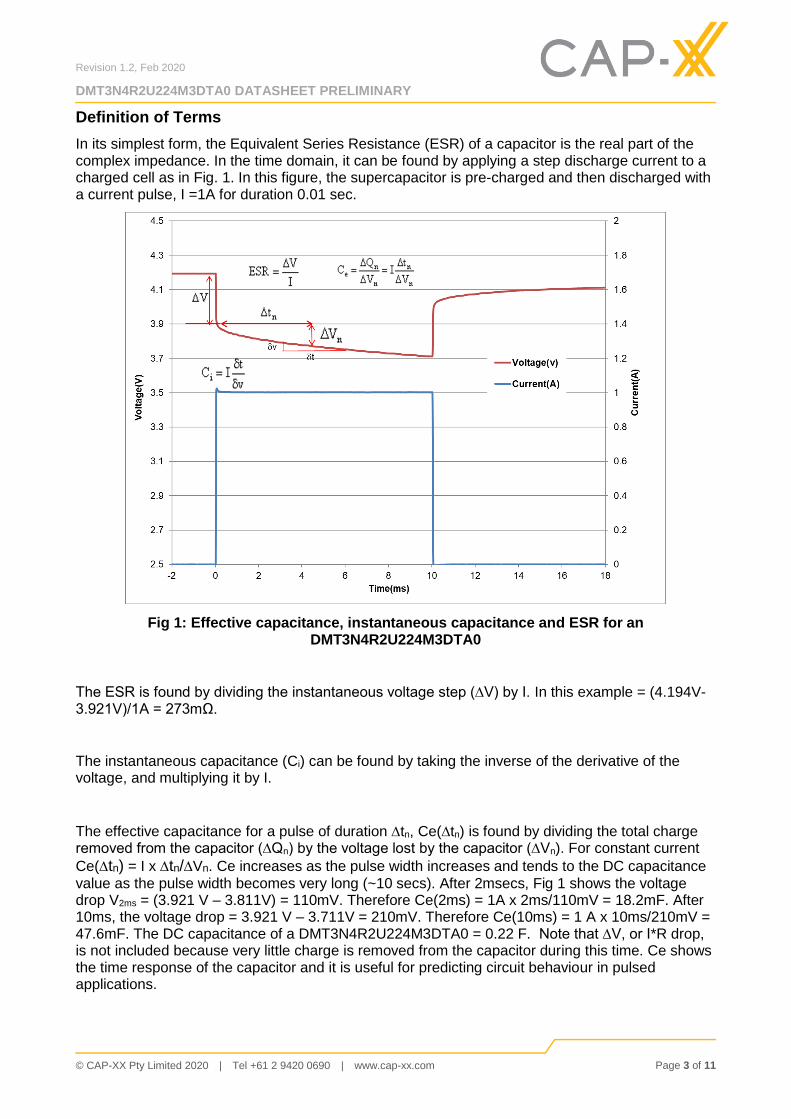
In its simplest form, the Equivalent Series Resistance (ESR) of a capacitor is the real part of the complex impedance. In the time domain, it can be found by applying a step discharge current to a charged cell as in Fig. 1. In this figure, the supercapacitor is pre-charged and then discharged with a current pulse, I =1A for duration 0.01 sec.
Fig 1: Effective capacitance, instantaneous capacitance and ESR for an DMT3N4R2U224M3DTA0
The ESR is found by dividing the instantaneous voltage step (∆V) by I. In this example = (4.194V-3.921V)/1A = 273mΩ.
The instantaneous capacitance (Ci) can be found by taking the inverse of the derivative of the voltage, and multiplying it by I.
The effective capacitance for a pulse of duration tn, Ce(tn) is found by dividing the total charge removed from the capacitor (∆Qn) by the voltage lost by the capacitor (∆Vn). For constant current
Ce(tn) = I x tn/Vn. Ce increases as the pulse width increases and tends to the DC capacitance
value as the pulse width becomes very long (~10 secs). After 2msecs, Fig 1 shows the voltage drop V2ms = (3.921 V – 3.811V) = 110mV. Therefore Ce(2ms) = 1A x 2ms/110mV = 18.2mF. After 10ms, the voltage drop = 3.921 V – 3.711V = 210mV. Therefore Ce(10ms) = 1 A x 10ms/210mV = 47.6mF. The DC capacitance of a DMT3N4R2U224M3DTA0 = 0.22 F. Note that ∆V, or I*R drop, is not included because very little charge is removed from the capacitor during this time. Ce shows the time response of the capacitor and it is useful for predicting circuit behaviour in pulsed applications.
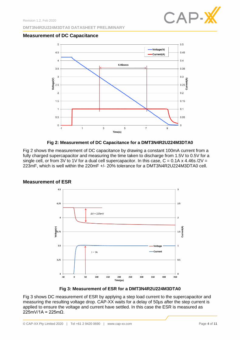
Fig 2: Measurement of DC Capacitance for a DMT3N4R2U224M3DTA0
Fig 2 shows the measurement of DC capacitance by drawing a constant 100mA current from a fully charged supercapacitor and measuring the time taken to discharge from 1.5V to 0.5V for a single cell, or from 3V to 1V for a dual cell supercapacitor. In this case, C = 0.1A x 4.46s /2V = 223mF, which is well within the 220mF +/- 20% tolerance for a DMT3N4R2U224M3DTA0 cell.
Measurement of ESR
Fig 3: Measurement of ESR for a DMT3N4R2U224M3DTA0
Fig 3 shows DC measurement of ESR by applying a step load current to the supercapacitor and measuring the resulting voltage drop. CAP-XX waits for a delay of 50µs after the step current is applied to ensure the voltage and current have settled. In this case the ESR is measured as 225mV/1A = 225mΩ.
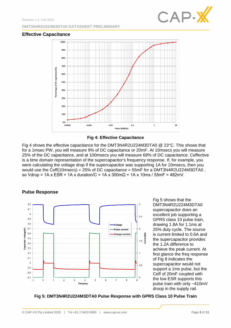
Fig 4 shows the effective capacitance for the DMT3N4R2U224M3DTA0 @ 23°C. This shows that for a 1msec PW, you will measure 9% of DC capacitance or 20mF. At 10msecs you will measure 25% of the DC capacitance, and at 100msecs you will measure 69% of DC capacitance. Ceffective is a time domain representation of the supercapacitor's frequency response. If, for example, you were calculating the voltage drop if the supercapacitor was supporting 1A for 10msecs, then you would use the Ceff(10msecs) = 25% of DC capacitance = 55mF for a DMT3N4R2U224M3DTA0 , so Vdrop = 1A x ESR + 1A x duration/C = 1A x 300mΩ + 1A x 10ms / 55mF = 482mV.
Pulse Response
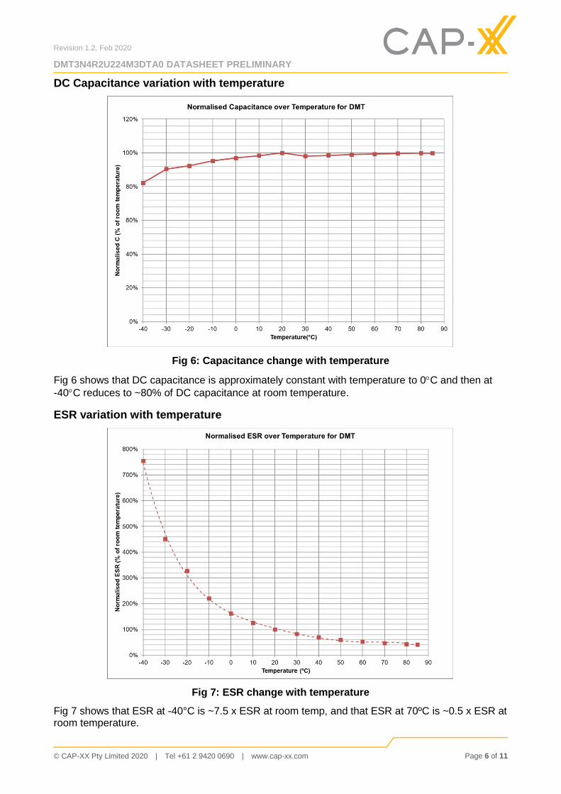
Fig 5 shows that the DMT3N4R2U224M3DTA0 supercapacitor does an excellent job supporting a GPRS class 10 pulse train, drawing 1.8A for 1.1ms at 25% duty cycle. The source is current limited to 0.6A and the supercapacitor provides the 1.2A difference to achieve the peak current. At first glance the freq response of Fig 8 indicates the supercapacitor would not support a 1ms pulse, but the Ceff of 20mF coupled with the low ESR supports this pulse train with only ~410mV droop in the supply rail.
Fig 5: DMT3N4R2U224M3DTA0 Pulse Response with GPRS Class 10 Pulse Train
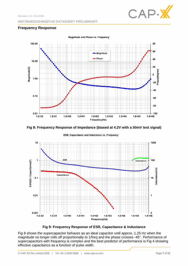
Fig 8: Frequency Response of Impedance (biased at 4.2V with a 50mV test signal)
Fig 9: Frequency Response of ESR, Capacitance & Inductance
Fig 8 shows the supercapacitor behaves as an ideal capacitor until approx. 1.25 Hz when the magnitude no longer rolls off proportionally to 1/freq and the phase crosses -45°. Performance of supercapacitors with frequency is complex and the best predictor of performance is Fig 4 showing effective capacitance as a function of pulse width.
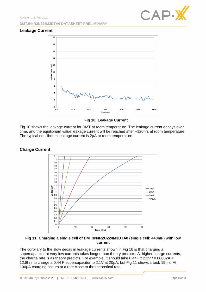
Fig 10 shows the leakage current for DMT at room temperature. The leakage current decays over time, and the equilibrium value leakage current will be reached after ~120hrs at room temperature. The typical equilibrium leakage current is 2µA at room temperature.
Charge Current
Fig 11: Charging a single cell of DMT3N4R2U224M3DTA0 (single cell: 440mF) with low current
The corollary to the slow decay in leakage currents shown in Fig 10 is that charging a supercapacitor at very low currents takes longer than theory predicts. At higher charge currents, the charge rate is as theory predicts. For example, it should take 0.44F x 2.1V / 0.00002A = 12.8hrs to charge a 0.44 F supercapacitor to 2.1V at 20µA, but Fig 11 shows it took 19hrs. At 100µA charging occurs at a rate close to the theoretical rate.
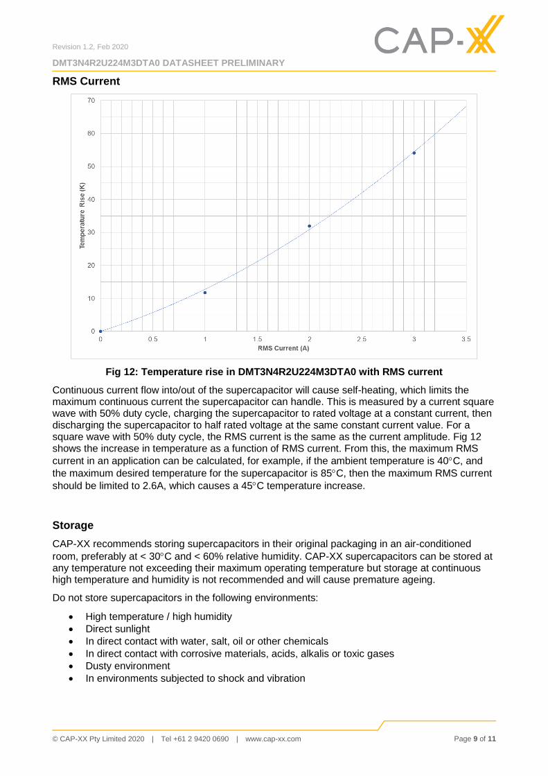
Fig 12: Temperature rise in DMT3N4R2U224M3DTA0 with RMS current
Continuous current flow into/out of the supercapacitor will cause self-heating, which limits the maximum continuous current the supercapacitor can handle. This is measured by a current square wave with 50% duty cycle, charging the supercapacitor to rated voltage at a constant current, then discharging the supercapacitor to half rated voltage at the same constant current value. For a square wave with 50% duty cycle, the RMS current is the same as the current amplitude. Fig 12 shows the increase in temperature as a function of RMS current. From this, the maximum RMS
current in an application can be calculated, for example, if the ambient temperature is 40C, and
the maximum desired temperature for the supercapacitor is 85C, then the maximum RMS current
should be limited to 2.6A, which causes a 45C temperature increase.
Storage
CAP-XX recommends storing supercapacitors in their original packaging in an air-conditioned
room, preferably at < 30C and < 60% relative humidity. CAP-XX supercapacitors can be stored at any temperature not exceeding their maximum operating temperature but storage at continuous high temperature and humidity is not recommended and will cause premature ageing.
Do not store supercapacitors in the following environments:
High temperature / high humidity
Direct sunlight
In direct contact with water, salt, oil or other chemicals
In direct contact with corrosive materials, acids, alkalis or toxic gases
CAP-XX supercapacitors are “burned in” during production, and have a defined polarity, as shown by the positive terminal marked on the face of the product. Reversing the polarity of the device will not damage the device but may cause a rise in the ESR and will void the warranty. Please verify the orientation of the supercapacitor in accordance with the product markings before assembly.
CAP-XX supercapacitors are heat-sensitive. Over-heating of the supercapacitor may result in a degradation of performance and useful life.
CAP-XX supercapacitors must only be used within their rated voltage range. Over-voltage may cause swelling and eventually, product failure.
CAP-XX supercapacitors are fully discharged when shipped. Devices should be handled and soldered in a discharged state.
Soldering and Assembling
CAP-XX supercapacitors are designed for direct soldering onto the PCB. Soldering the terminals to the PCB will ensure the highest contact reliability and lowest contact resistance. Do NOT solder directly to the device casing. This will cause permanent internal damage to the supercapacitor.
CAP-XX supercapacitors are NOT SUITABLE for infrared reflow soldering, hot-air reflow soldering, or wave soldering. They should be mounted as a secondary operation, using a manual soldering iron, a hot bar soldering jig, conductive adhesive, ultrasonic welding or laser welding.
CAP-XX recommends the use of a water-soluble flux, or a no-clean (low residue) flux, and low temperature solder compounds.
Shock CAP-XX has undertaken tests to determine the effects of repeated shocks on both the mechanical integrity and electrical performance of its supercapacitors:
Charge to rated voltage at 500mA for min. 30min
Type: Half-Sine
Amplitude: 500G
Duration: 1ms
No. of cycles: 3 in each direction (18 in total)
No. of axes: 3, orthogonal
Results: No electrical or mechanical degradation observed.
Note that this test was undertaken on the standard product with adhesive mounting tape (Nitto No.5000NS). To achieve the highest levels of resistance to shock, CAP-XX recommends the use of an adhesive mounting tape on the underside of the device.
Vibration CAP-XX has undertaken tests to determine the effects of sustained vibration on both the mechanical integrity and electrical performance of its supercapacitors:
Charge to rated voltage at 500mA for min. 30min
Type: Sinusoidal
Frequency: 10 ~ 500Hz/10G
Amplitude: 1.5mm
Sweep Rate: 1octave/min
No. of cycles: 10 in each direction
No. of axes: 3, orthogonal
Results: No electrical or mechanical degradation observed.
Note that this test was undertaken on the standard product with adhesive mounting tape (Nitto No.5000NS). To achieve the highest levels of resistance to shock, CAP-XX recommends the use of an adhesive mounting tape on the underside of the device.
Drop Test CAP-XX has undertaken tests to determine the effects of repeated drops on both the mechanical integrity and electrical performance of its supercapacitors:
Supercapacitor is discharged
Mount product to 150g box with adhesive mounting tape (Nitto No.5000NS)
Drop the box from 0.25m / 0.5m / 1.0m / 1.5m
Repeat 3 times for 6 sides (18 in total)
Results: No electrical or mechanical degradation observed.