Amarex N S 32-160 / 0 2 YL G-160 Type series Impeller type (S) Hydraulics size Motor designation Impeller diameter Number of poles Motor version (YLG only) Material variant G only Type series booklet 2563.51/3-10 Amarex ® N S 32 Submersible motor pumps DN 32 50 Hz Applications Amarex N S 32-160 submersible motor pumps are used for pumping waste water in intermittent operation, e.g. F Domestic waste water F Raw water F Waste water containing faeces Operating data Capacity Q up to 16 m 3 /h, 4.4 l/s Head H up to 29 m Motor rating P 2 1.5 kW Fluid temperature t up to 40 ¥ C Enclosure IP 68 to EN 60 529 / IEC 529 Design Wet-installed in stationary and transportable design. Submersible, single-stage, single-entry, non-self-priming close-coupled unit. Hydraulic system: with cutter (S). Designation Drive Asynchronous motor, 400 V, 50 Hz, direct starting, Max. switching frequency: 30 starts per hour YLG version in accordance with ATEX 100a, motor Ex d IIB T4, LCIE 07 ATEX 6016 X. Shaft seal -- motor end: 1 shaft seal ring -- pump end: 1 bi-rotational mechanical seal with oil reservoir filled with environmentally-friendly oil Bearings Grease-packed rolling element bearings sealed for life. Motor variants No variants available Please note: Variable-speed operation of this pump is not allowed. YL ⇒ motor only with explosion protection T4 (40 ¥ C) Operating mode S1 -- submerged (max. 25 m) Operating mode S3 – not submerged (see dimension table) -- EN 12 050 LGA approval No.: 7381257--01z
Transcript
Amarex N S 32-160 / 0 2 YL G-160Type seriesImpeller type (S)
Hydraulics size
Motor designation
Impeller diameter
Number of polesMotor version (YLG only)
Material variantG only
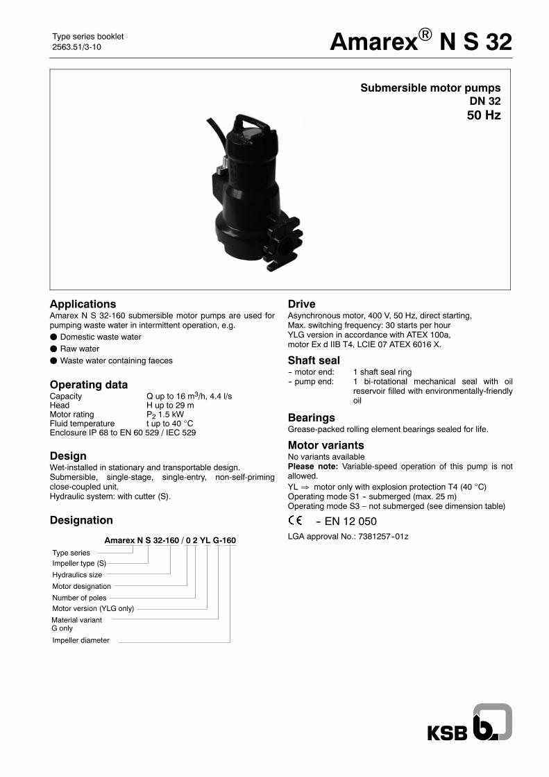
Type series booklet2563.51/3-10 Amarex® N S 32
Submersible motor pumpsDN 3250 Hz
ApplicationsAmarex N S 32-160 submersible motor pumps are used forpumping waste water in intermittent operation, e.g.F Domestic waste waterF Raw waterF Waste water containing faeces
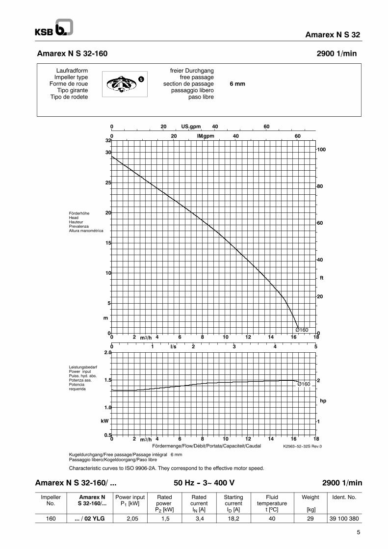
Operating dataCapacity Q up to 16 m3/h, 4.4 l/sHead H up to 29 mMotor rating P2 1.5 kWFluid temperature t up to 40 ¥CEnclosure IP 68 to EN 60 529 / IEC 529
DesignWet-installed in stationary and transportable design.Submersible, single-stage, single-entry, non-self-primingclose-coupled unit.Hydraulic system: with cutter (S).
Designation
DriveAsynchronous motor, 400 V, 50 Hz, direct starting,Max. switching frequency: 30 starts per hourYLG version in accordance with ATEX 100a,motor Ex d IIB T4, LCIE 07 ATEX 6016 X.
Shaft seal-- motor end: 1 shaft seal ring-- pump end: 1 bi-rotational mechanical seal with oil
reservoir filled with environmentally-friendlyoil
BearingsGrease-packed rolling element bearings sealed for life.
Motor variantsNo variants availablePlease note: Variable-speed operation of this pump is notallowed.YL ⇒ motor only with explosion protection T4 (40 ¥C)Operating mode S1 -- submerged (max. 25 m)Operating mode S3 – not submerged (see dimension table)
-- EN 12 050LGA approval No.: 7381257--01z
Double winding temperaturemonitoring enables automa-tic operation, even whereexplosion protection require-ments have to be met.
Product Advantages at the Example of
Amarex N S 32-160 YLGto Our Customers’ Benefit
Absolutely watertight cable entry.Multiple safety due to:
Individual conductors stripped, tinnedand sealed in resin.
New kind of cable entry
Your benefit:Easy-to-connect polarisedcable entry enables fastcable installation / removal
Shaft made ofcorrosion-resistantstainless steel
Your benefit:No corrosion pro-blems, thereforelong service lives.
Automatic, bolt-freeconnection for stationaryinstallation; leakageprevented by elastic sealing.
Your benefit:The most simple and at thesame time mostoperator-friendly solution:Easy installation andremoval of the pump.
Your benefit:The pump can be operated safelyeven in the event of damage to thecable sheath and core insulation.
Amarex N S 32
2
Amarex N S 32
3
Materials
Variant G
Pump casing JL 1040
Intermediate casing JL 1040
Impeller JL 1040
Cutter 1.2842 (90Mn V8G)
Shaft 1.4021
Shaft seal ring(motor-end) NBR
Mechanical seal(pump-end) SiC / SiC
Screws/bolts A2
Sealing elements NBR
Scope of supplyPump (Ident. No. 39 ... ...) and accessories in separatepackages, available ex stock.
D Pump unit (P1):-- Material variant: Grey cast iron-- Motor design: Explosion-proof (YL)-- Cable gland: Totally watertight, resin-mounted-- Complete pump, ready for installation, with 10m power sup-
ply cable 7 x 1.5 mm2
-- Standard finish: Surface treatmentSA2 1/2 SIS 055900
Layout No. 1 Layout No. 2Guide hoop arrangement Direct connection to discharge pipeSingle-pump station for 1.5 -- 1.8 m installation depth Single-pump stationDuckfoot bend Suspended installation
Layout No. 3 Layout No. 4Single-pump station for 4.5 m installation depth Duplex-pump station for 4.5 m installation depthOptionally with guide wire Optionally with guide wire
single guide rail single guide railor twin guide rails or twin guide rails
Duckfoot bend Duckfoot bend
Amarex N S 32
12
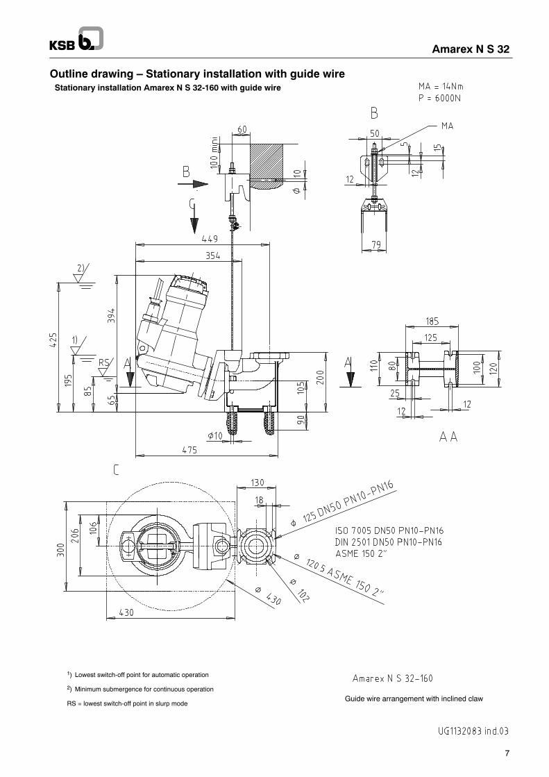
Suggested installation layouts Amarex N in stationary installation
Amarex N S 32 ø A B ø D E G K L M N O DN1
1 pump2 pumps
430--
165165
800800
--300
7575
150150
5757
--400
--600
--151
3232
The dimensions given are minimum dimensions in mm.Pump dimensions see dimensions table
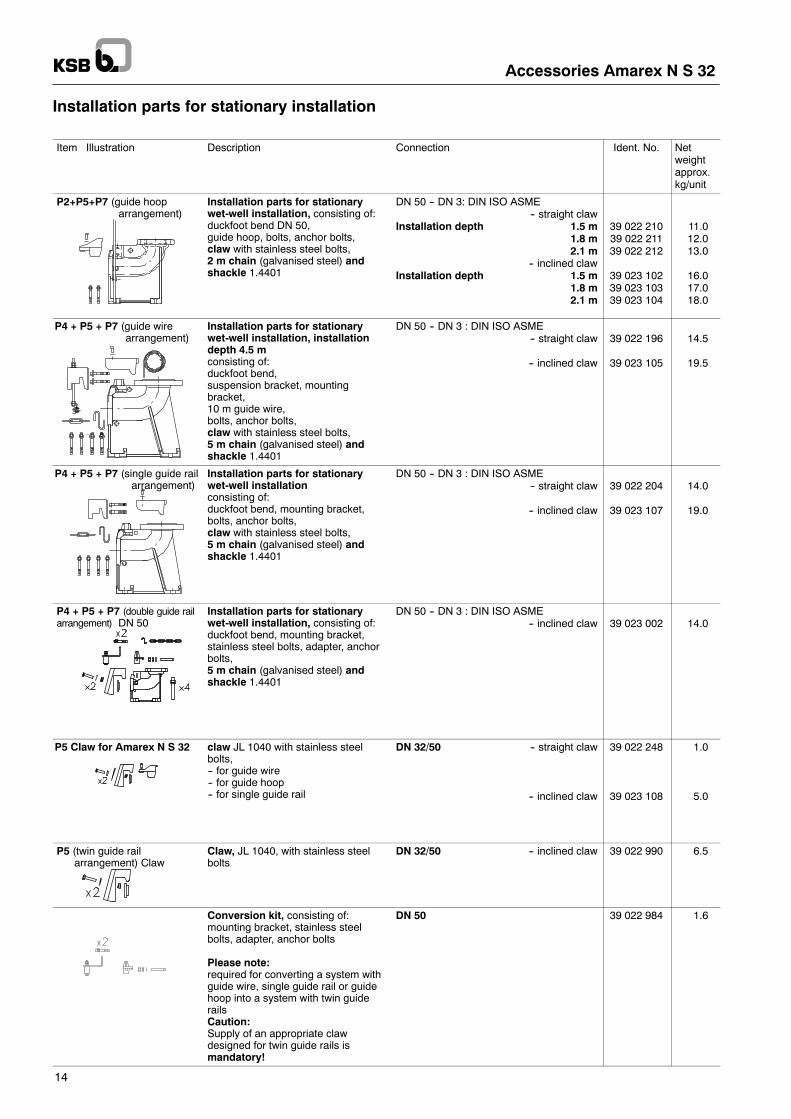
Installation parts for stationarywet-well installation, consisting of:duckfoot bend DN 50,guide hoop, bolts, anchor bolts,claw with stainless steel bolts,2 m chain (galvanised steel) andshackle 1.4401
DN 50 -- DN 3: DIN ISO ASME-- straight claw
Installation depth 1.5 m1.8 m2.1 m
-- inclined clawInstallation depth 1.5 m
1.8 m2.1 m
39 022 21039 022 21139 022 212
39 023 10239 023 10339 023 104
11.012.013.0
16.017.018.0
P4 + P5 + P7 (guide wirearrangement)
Installation parts for stationarywet-well installation, installationdepth 4.5 mconsisting of:duckfoot bend,suspension bracket, mountingbracket,10 m guide wire,bolts, anchor bolts,claw with stainless steel bolts,5 m chain (galvanised steel) andshackle 1.4401
DN 50 -- DN 3 : DIN ISO ASME-- straight claw
-- inclined claw
39 022 196
39 023 105
14.5
19.5
P4 + P5 + P7 (single guide railarrangement)
Installation parts for stationarywet-well installationconsisting of:duckfoot bend, mounting bracket,bolts, anchor bolts,claw with stainless steel bolts,5 m chain (galvanised steel) andshackle 1.4401
DN 50 -- DN 3 : DIN ISO ASME-- straight claw
-- inclined claw
39 022 204
39 023 107
14.0
19.0
P4 + P5 + P7 (double guide railarrangement) DN 50
Installation parts for stationarywet-well installation, consisting of:duckfoot bend, mounting bracket,stainless steel bolts, adapter, anchorbolts,5 m chain (galvanised steel) andshackle 1.4401
DN 50 -- DN 3 : DIN ISO ASME-- inclined claw 39 023 002 14.0
P5 Claw for Amarex N S 32 claw JL 1040 with stainless steelbolts,-- for guide wire-- for guide hoop-- for single guide rail
Please note:required for converting a system withguide wire, single guide rail or guidehoop into a system with twin guiderailsCaution:Supply of an appropriate clawdesigned for twin guide rails ismandatory!
DN 50 39 022 984 1.6
50
Accessories Amarex N S 32
15
Installation parts for transportable model
Item Illustration Description Connection Ident. No. Net weightapprox. kg/unit
P6 Feet (3) Amarex N DN 32 39 023 085 0.25
(for uneven mounting surfaces only)Pump foot padincluding screws(can be used in combination with feet only!)
Amarex N DN 32 to 100 39 022 262 0.6
Chain for stationary and transportable models
Item Illustration Description Sizes Safe working loadkg
Ident. No. Net weightapprox. kg/unit
P7 Chain (galvanised steel),shackle 1.4401 andhook 1.45712 m B5 x 35 160 19 141 819 1.5
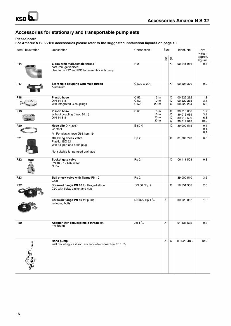
Accessories for stationary and transportable pump setsPlease note:For Amarex N S 32--160 accessories please refer to the suggested installation layouts on page 10.
P21 RK swing check valvePlastic, ISO 7/Iwith full port and drain plug
Not suitable for pumped drainage
Rp 2 X 01 009 773 0.6
P22 Socket gate valvePN 10 -- 12 DIN 3352CuZn
Rp 2 X 00 411 503 0.8
P23 Ball check valve with flange PN 10Cast
Rp 2 39 000 510 3.6
P27 Screwed flange PN 16 for flanged elbow DN 50 / Rp 2C50 with bolts, gasket and nuts
X 19 551 353 2.0
Screwed flange PN 40 for pump DN 32 / Rp 1 1/4including bolts
X 39 023 087 1.8
P30 Adapter with reduced male thread M4 2 x 1 1/4EN 1042K
X 01 135 663 0.3
Hand pump,wall mounting, cast iron, suction-side connection Rp 1 1/2
X X 00 520 485 12.0
CEE motor protection plug
E9
Accessories Amarex N S 32
17
Suggested Electrical Installation Layouts
Note! Amarex N S 32-160 is available in explosion-proof design only!
Accessories Amarex N S 32
18
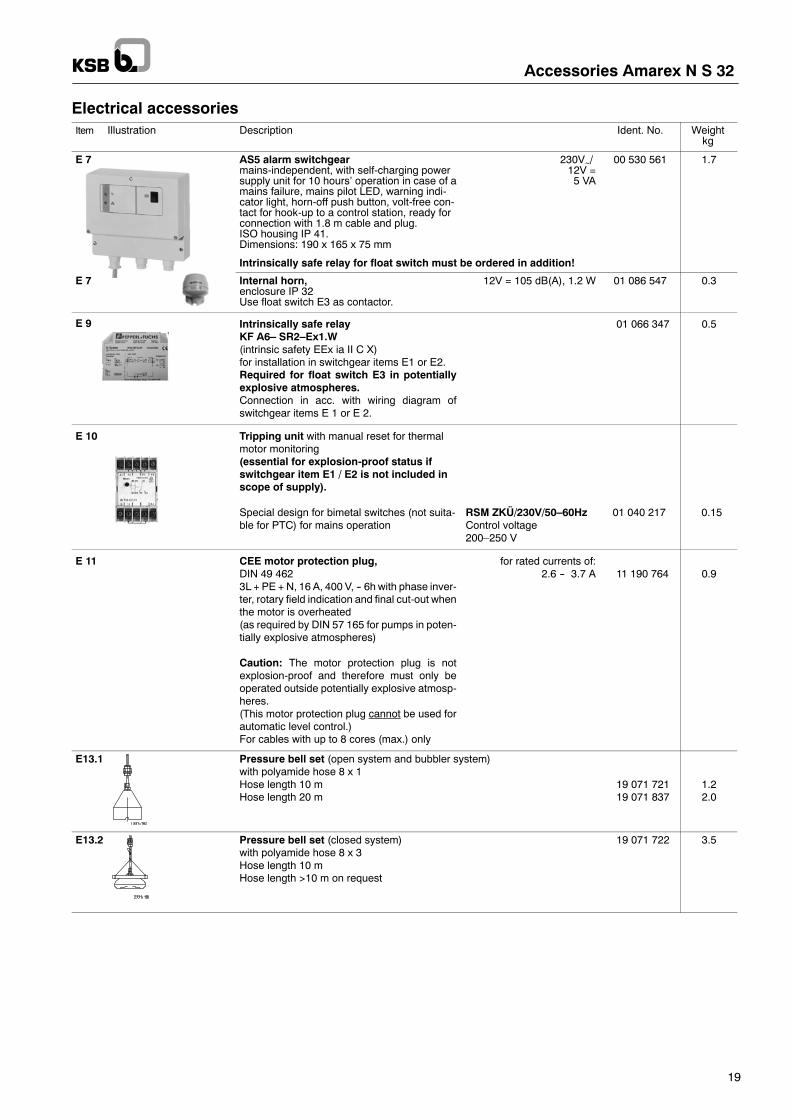
Electrical accessories
Selection table for switchgear(For further switchgear models for single / duplex pumps and Hyper motor protection switch please referto catalogue booklet).
Explosion-proofSwitchgear for: Rated current in Asingle pumpingstation (1 pump)
E1 Switchgear for single pumping stationwith motor protection switch,manual-0-automatic selector switch and motorcontactor (EDE) 1).
Indicator lamps and volt-free contacts foroperation and fault indication. Terminals forfloat switch. Thermal monitoring circuit 2 withkeys.
Rated voltage 400 V, 50 Hzenclosure IP 54
EDE 40.1 300 x 400 x 150 29 128 0159.3
E1 LevelControl AdvancedControl unit for single pump, IP 54Power range up to 10 A, 4 kW,3~400 V PE+N, direct starting
E13 H03 pneumatic sensor (hydrostatic pressuremeasurement without compressor):internal pressure sensor up to 3.5 m water co-lumn
CU-1 10 H03 255 x 216 x 100 01 118 726 3.0
H10 pneumatic sensor (hydrostatic pressuremeasurement without compressor):internal pressure sensor up to 10.5 m watercolumn
CU-1 10 H10 255 x 216 x 100 01 118 727 3.0
A02 bubbler system: internal pressure sensorwith compressor up to 2 m tank depth
SU-1 10 A02 300 x 400 x 155 01 119 203 10.0
A03 bubbler system: internal pressure sensorwith compressor up to 3 m tank depth
SU-1 10 A03 300 x 400 x 155 01 119 204 10.0
E2 Switchgear for duplex pumping stations 1)with automatic alternate, stand-by andpeak-load operation function, with one motorprotection switch each, manual-0-automaticselector switch and motor contactor (DDE),indicator lamps for manual operation, operationpump 1, operation pump 2 and fault indication.V l f f i d f l
DDE 40.1 400 x 600 x 200 29 128 060 18.0
pump 1, operation pump 2 and fault indication.Volt-free contacts for operation and fault.Connections for float switch on terminal strip.Thermal monitoring circuit 2 with keys.
Rated voltage 400 V, 50 Hzenclosure IP 54
E2 LevelControl AdvancedControl unit for two pumps, IP 54Power range up to 10 A, 4 kW,3~400 V PE+N, direct starting
E13 H03 pneumatic sensor (hydrostatic pressuremeasurement without compressor):internal pressure sensor up to 3.5 m water co-lumn
CU-2 10 H03 255 x 216 x 100 01 118 728 3.0
H10 pneumatic sensor (hydrostatic pressuremeasurement without compressor):internal pressure sensor up to 10.5 m watercolumn
CU-2 10 H10 255 x 216 x 100 01 118 729 3.0
A02 bubbler system: internal pressure sensorwith compressor up to 2 m tank depth
SU-2 10 A02 300 x 400 x 155 01 119 205 19.0
A03 bubbler system: internal pressure sensorwith compressor up to 3 m tank depth
SU-2 10 A03 300 x 400 x 155 01 119 206 19.0
1) Intrinsically safe relays for float switches must be ordered in addition (item E9)
E 7 AS5 alarm switchgearmains-independent, with self-charging powersupply unit for 10 hours’ operation in case of amains failure, mains pilot LED, warning indi-cator light, horn-off push button, volt-free con-tact for hook-up to a control station, ready forconnection with 1.8 m cable and plug.ISO housing IP 41.Dimensions: 190 x 165 x 75 mm
230V~/12V =5 VA
00 530 561 1.7
Intrinsically safe relay for float switch must be ordered in addition!
E 7 Internal horn,enclosure IP 32Use float switch E3 as contactor.
12V = 105 dB(A), 1.2 W 01 086 547 0.3
E 9 Intrinsically safe relayKF A6– SR2–Ex1.W(intrinsic safety EEx ia II C X)for installation in switchgear items E1 or E2.Required for float switch E3 in potentiallyexplosive atmospheres.Connection in acc. with wiring diagram ofswitchgear items E 1 or E 2.
01 066 347 0.5
E 10 Tripping unit with manual reset for thermalmotor monitoring(essential for explosion-proof status ifswitchgear item E1 / E2 is not included inscope of supply).
Special design for bimetal switches (not suita-ble for PTC) for mains operation
RSM ZKÜ/230V/50–60HzControl voltage200–250 V
01 040 217 0.15
E 11 CEE motor protection plug,DIN 49 4623L + PE +N, 16 A, 400 V, -- 6h with phase inver-ter, rotary field indication and final cut-out whenthe motor is overheated(as required by DIN 57 165 for pumps in poten-tially explosive atmospheres)
Caution: The motor protection plug is notexplosion-proof and therefore must only beoperated outside potentially explosive atmosp-heres.(This motor protection plug cannot be used forautomatic level control.)For cables with up to 8 cores (max.) only
for rated currents of:2.6 -- 3.7 A 11 190 764 0.9
E13.1 Pressure bell set (open system and bubbler system)with polyamide hose 8 x 1Hose length 10 mHose length 20 m
19 071 72119 071 837
1.22.0
E13.2 Pressure bell set (closed system)with polyamide hose 8 x 3Hose length 10 mHose length >10 m on request
19 071 722 3.5
2563.51/3-10
/1.10.2008
Subjecttotechnicalm
odifications
withoutpriornotice.
Amarex N S 32
Options (control cabinet extension may be necessary)
Item Description Weightkg
O 1 Operating hours counter 0.1
O 2 Ammeter 0.1
O 3 Voltmeter with changeover switch 0.1
O 4 Master switch 0.2
O 6 Monitoring relay (phase failure/sequence, under/over-voltage) 0.4
O 7 Integrated, mains-independent alarm and charging unit PZ033 Nfor hook-up to alarm equipment, e.g. horn or flashlight (Imax approx. 150 mA) andcharging a rechargeable battery 12 V, 1.2 Ah, with rechargeable battery, lead-gel rechargeable battery 12 V, 1.2 Ah
1.0
O 7.1 Alarm equipment for PZ033 NFlashlight 12V IP 65 (for EDEL/DDEL FLS supplied in mounted condition).Horn 12 V, approx. 90 dB(A), IP 33 for indoor and outdoor installation, mount in aposition where it is protected against direct rain.