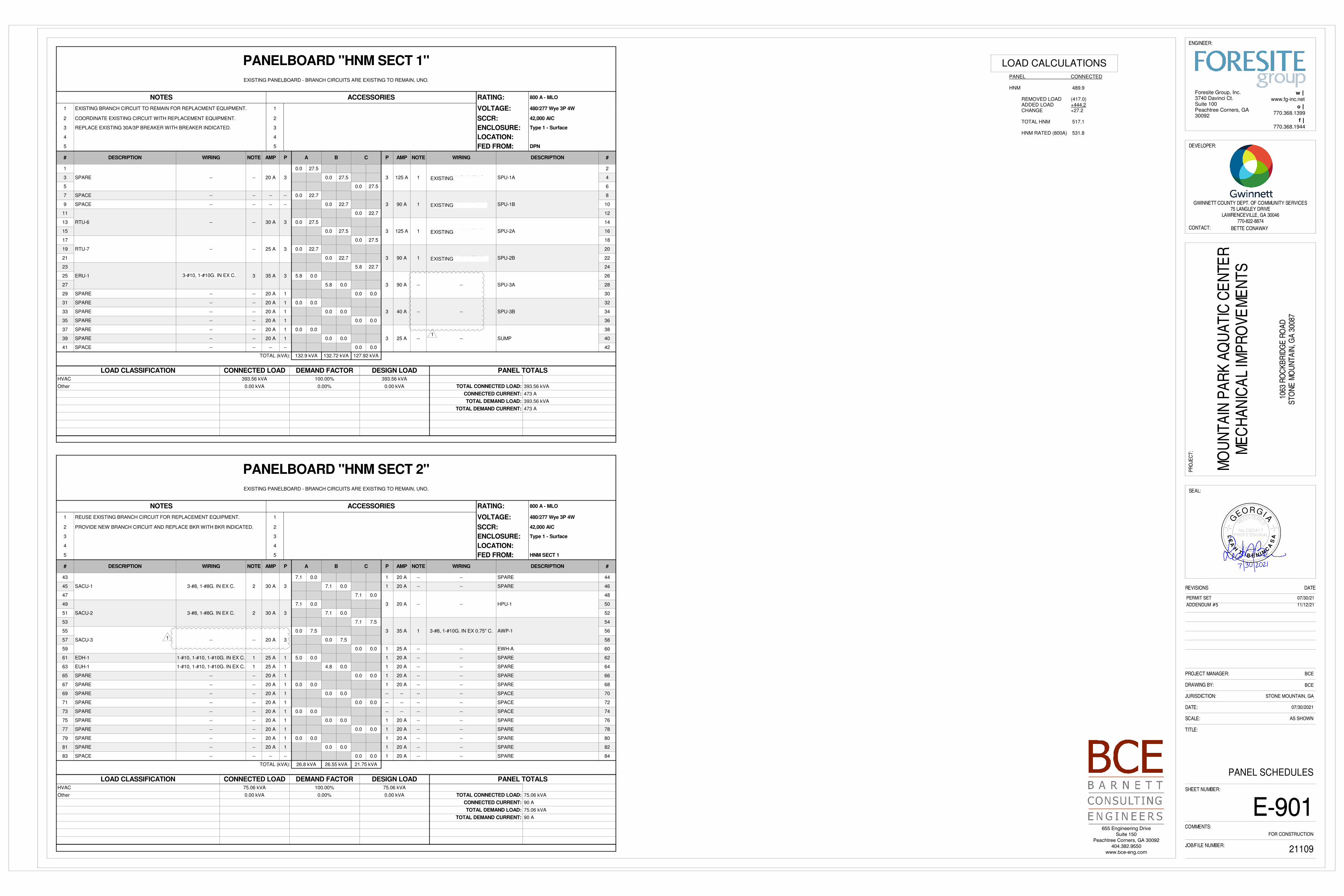
November 12, 2021 ADDENDUM #5 BL0115-21, Mountain Park Aquatic Center Mechanical Improvements ATTACHMENTS: 1. Sheet M-000 2. Sheet M-103 3. Sheet M-104 4. Sheet M-203 5. Sheet M-204 6. Sheet M-601 7. Sheet E-103 8. Sheet E-104 9. Sheet E-203 10. Sheet E-204 11. Sheet E-900 12. Sheet E-901 13. Revised Specification 23 7200 Energy Recovery Units 14. Revised Specification 23 8419 Pool Dehumidification Units STATEMENTS: S1. This Addendum #5 forms a part of the contract documents and modifies and supercedes the original ITB documents and previous addendums as noted. PLANS: 1. Clouded changes for revised sheets are noted below: M-000 - Remove all references to SPU-3 In-Frame Rebuild Scope of Work. M-103 - Remove all demolition work related to the SPU-3 In-Frame Rebuild. M-104 - Remove all demolition work related to the SPU-3 In-Frame Rebuild. M-203 - Remove all new work related to the SPU-3 In-Frame Rebuild. M-204 - Remove all new work related to the SPU-3 In-Frame Rebuild. M-601 - Modify controls scope of work as they relate to SPU-3. E-103 - Remove all demolition work related to the SPU-3 In-Frame Rebuild. E-104 - Remove all demolition work related to the SPU-3 In-Frame Rebuild. E-203 - Remove all new work related to the SPU-3 In-Frame Rebuild. E-204 - Remove all new work related to the SPU-3 In-Frame Rebuild. E-900 - Remove all work related to the SPU-3 In-Frame Rebuild from mechanical equipment connection schedule. E-901 - Remove all work related to the SPU-3 In-Frame Rebuild from the panel schedules.
Transcript
November 12, 2021
ADDENDUM #5 BL0115-21, Mountain Park Aquatic Center Mechanical Improvements
S1. This Addendum #5 forms a part of the contract documents and modifies and supercedes the
original ITB documents and previous addendums as noted. PLANS: 1. Clouded changes for revised sheets are noted below:
M-000 - Remove all references to SPU-3 In-Frame Rebuild Scope of Work. M-103 - Remove all demolition work related to the SPU-3 In-Frame Rebuild. M-104 - Remove all demolition work related to the SPU-3 In-Frame Rebuild. M-203 - Remove all new work related to the SPU-3 In-Frame Rebuild. M-204 - Remove all new work related to the SPU-3 In-Frame Rebuild. M-601 - Modify controls scope of work as they relate to SPU-3. E-103 - Remove all demolition work related to the SPU-3 In-Frame Rebuild. E-104 - Remove all demolition work related to the SPU-3 In-Frame Rebuild. E-203 - Remove all new work related to the SPU-3 In-Frame Rebuild. E-204 - Remove all new work related to the SPU-3 In-Frame Rebuild. E-900 - Remove all work related to the SPU-3 In-Frame Rebuild from mechanical
equipment connection schedule. E-901 - Remove all work related to the SPU-3 In-Frame Rebuild from the panel
schedules.
SPECIFICATIONS: 1. Replace Specification 23 7200 Energy Recovery Units with enclosed Revised Specification 23
7200 Energy Recovery Units. 2. Replace Specification 23 8419 Pool Dehumidification Units with enclosed Revised
Specification 23 8419 Pool Dehumidification Units.
Thank you,
Jake Scarpone Jake Scarpone Purchasing Associate II
TITLE:
DATE:
JURISDICTION:
DRAWING BY:
PROJECT MANAGER:
SHEET NUMBER:
COMMENTS:
SEAL:
DEVELOPER:
PROJ
ECT:
CONTACT:
DATEREVISIONS
ENGINEER:
SCALE:
JOB/FILE NUMBER:
w |
o |
f |
GWINNETT COUNTY DEPT. OF COMMUNITY SERVICES75 LANGLEY DRIVE
LAWRENCEVILLE, GA 30046770-822-8874
BETTE CONAWAY
MOUN
TAIN
PAR
K AQ
UATI
C CE
NTER
MECH
ANIC
AL IM
PROV
EMEN
TS
1063
ROC
KBRI
DGE
ROAD
STON
E MO
UNTA
IN, G
A 30
087
21JS23
07/30/2021
AS SHOWN
MLW
JSA
STONE MOUNTAIN, GA
FOR CONSTRUCTION
PERMIT SET 07/30/21
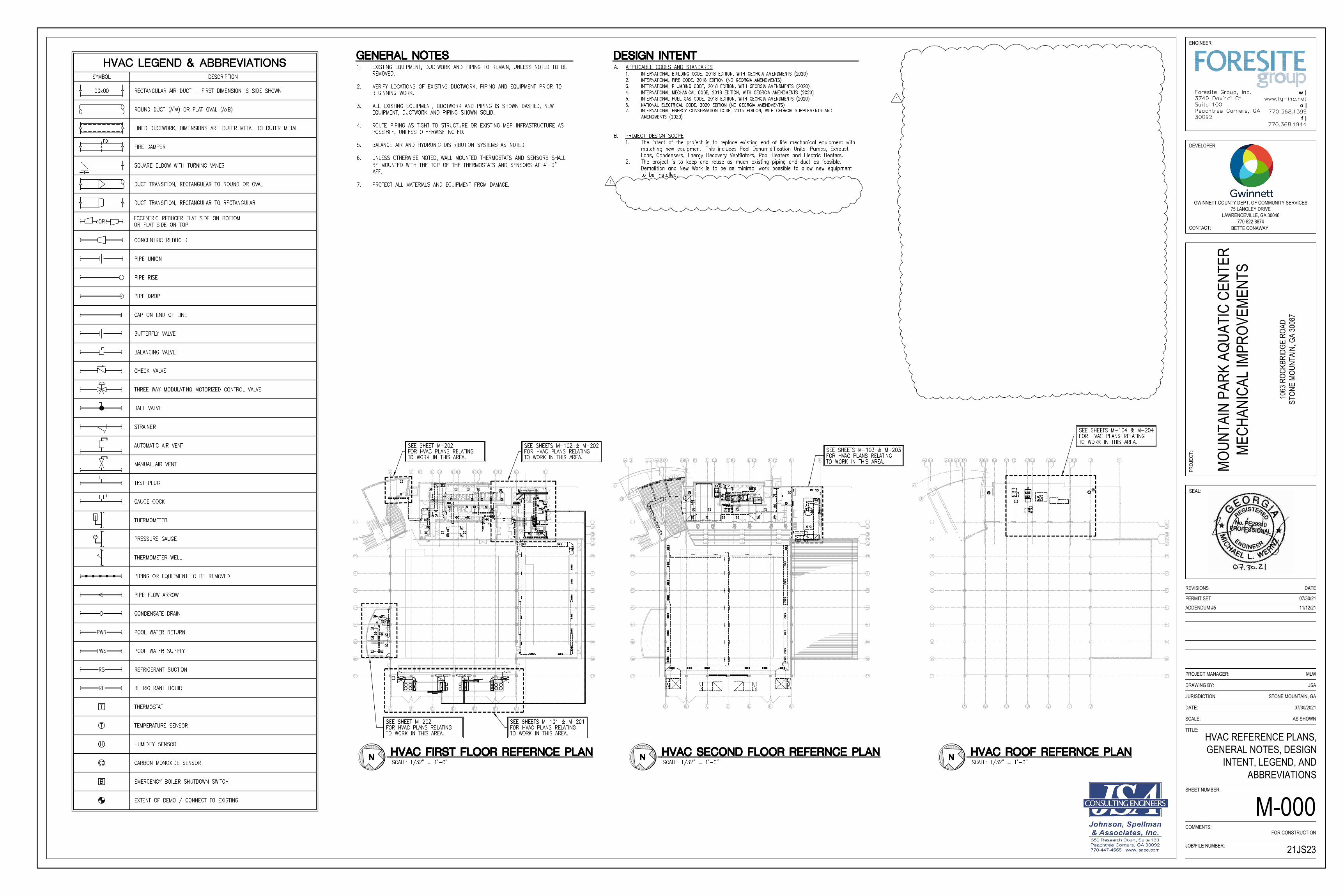
HVAC REFERENCE PLANS,GENERAL NOTES, DESIGN
INTENT, LEGEND, ANDABBREVIATIONS
M-000
11/12/21ADDENDUM #5
AutoCAD SHX Text
SEE SHEETS M-102 & M-202
AutoCAD SHX Text
FOR HVAC PLANS RELATING
AutoCAD SHX Text
TO WORK IN THIS AREA.
AutoCAD SHX Text
A
AutoCAD SHX Text
1
AutoCAD SHX Text
B
AutoCAD SHX Text
C
AutoCAD SHX Text
D
AutoCAD SHX Text
E
AutoCAD SHX Text
F
AutoCAD SHX Text
G
AutoCAD SHX Text
B.2
AutoCAD SHX Text
C.2
AutoCAD SHX Text
D.2
AutoCAD SHX Text
E.2
AutoCAD SHX Text
F.2
AutoCAD SHX Text
H
AutoCAD SHX Text
1.1
AutoCAD SHX Text
1.9
AutoCAD SHX Text
2
AutoCAD SHX Text
2.1
AutoCAD SHX Text
3
AutoCAD SHX Text
4
AutoCAD SHX Text
5
AutoCAD SHX Text
6
AutoCAD SHX Text
7
AutoCAD SHX Text
8
AutoCAD SHX Text
9
AutoCAD SHX Text
10
AutoCAD SHX Text
A
AutoCAD SHX Text
B
AutoCAD SHX Text
C
AutoCAD SHX Text
D
AutoCAD SHX Text
E
AutoCAD SHX Text
F
AutoCAD SHX Text
G
AutoCAD SHX Text
1
AutoCAD SHX Text
2
AutoCAD SHX Text
3
AutoCAD SHX Text
4
AutoCAD SHX Text
5
AutoCAD SHX Text
6
AutoCAD SHX Text
7
AutoCAD SHX Text
8
AutoCAD SHX Text
9
AutoCAD SHX Text
10
AutoCAD SHX Text
FD
AutoCAD SHX Text
FD
AutoCAD SHX Text
FD
AutoCAD SHX Text
FD
AutoCAD SHX Text
FD
AutoCAD SHX Text
FD
AutoCAD SHX Text
FD
AutoCAD SHX Text
B
AutoCAD SHX Text
B
AutoCAD SHX Text
CO
AutoCAD SHX Text
CO
AutoCAD SHX Text
T
AutoCAD SHX Text
T
AutoCAD SHX Text
SEE SHEETS M-101 & M-201
AutoCAD SHX Text
FOR HVAC PLANS RELATING
AutoCAD SHX Text
TO WORK IN THIS AREA.
AutoCAD SHX Text
SEE SHEET M-202
AutoCAD SHX Text
FOR HVAC PLANS RELATING
AutoCAD SHX Text
TO WORK IN THIS AREA.
AutoCAD SHX Text
SEE SHEET M-202
AutoCAD SHX Text
FOR HVAC PLANS RELATING
AutoCAD SHX Text
TO WORK IN THIS AREA.
AutoCAD SHX Text
SYMBOL
AutoCAD SHX Text
ROUND DUCT (A"%%C) OR FLAT OVAL (AxB)
AutoCAD SHX Text
SQUARE ELBOW WITH TURNING VANES
AutoCAD SHX Text
OR
AutoCAD SHX Text
PIPE UNION
AutoCAD SHX Text
PIPE RISE
AutoCAD SHX Text
CAP ON END OF LINE
AutoCAD SHX Text
BALANCING VALVE
AutoCAD SHX Text
THREE WAY MODULATING MOTORIZED CONTROL VALVE
AutoCAD SHX Text
STRAINER
AutoCAD SHX Text
PIPE FLOW ARROW
AutoCAD SHX Text
HVAC LEGEND & ABBREVIATIONS
AutoCAD SHX Text
DESCRIPTION
AutoCAD SHX Text
RECTANGULAR AIR DUCT - FIRST DIMENSION IS SIDE SHOWN
AutoCAD SHX Text
00x00
AutoCAD SHX Text
DUCT TRANSITION, RECTANGULAR TO ROUND OR OVAL
AutoCAD SHX Text
DUCT TRANSITION, RECTANGULAR TO RECTANGULAR
AutoCAD SHX Text
CONCENTRIC REDUCER
AutoCAD SHX Text
PIPE DROP
AutoCAD SHX Text
BUTTERFLY VALVE
AutoCAD SHX Text
CHECK VALVE
AutoCAD SHX Text
BALL VALVE
AutoCAD SHX Text
AUTOMATIC AIR VENT
AutoCAD SHX Text
MANUAL AIR VENT
AutoCAD SHX Text
TEST PLUG
AutoCAD SHX Text
PIPING OR EQUIPMENT TO BE REMOVED
AutoCAD SHX Text
CONDENSATE DRAIN
AutoCAD SHX Text
D
AutoCAD SHX Text
ECCENTRIC REDUCER FLAT SIDE ON BOTTOM OR FLAT SIDE ON TOP
AutoCAD SHX Text
FIRE DAMPER
AutoCAD SHX Text
FD
AutoCAD SHX Text
THERMOMETER
AutoCAD SHX Text
THERMOMETER WELL
AutoCAD SHX Text
PRESSURE GAUGE
AutoCAD SHX Text
GAUGE COCK
AutoCAD SHX Text
POOL WATER RETURN
AutoCAD SHX Text
PWR
AutoCAD SHX Text
POOL WATER SUPPLY
AutoCAD SHX Text
PWS
AutoCAD SHX Text
THERMOSTAT
AutoCAD SHX Text
EXTENT OF DEMO / CONNECT TO EXISTING
AutoCAD SHX Text
CARBON MONOXIDE SENSOR
AutoCAD SHX Text
EMERGENCY BOILER SHUTDOWN SWITCH
AutoCAD SHX Text
CO
AutoCAD SHX Text
B
AutoCAD SHX Text
T
AutoCAD SHX Text
REFRIGERANT SUCTION
AutoCAD SHX Text
RS
AutoCAD SHX Text
REFRIGERANT LIQUID
AutoCAD SHX Text
RL
AutoCAD SHX Text
TEMPERATURE SENSOR
AutoCAD SHX Text
T
AutoCAD SHX Text
HUMIDITY SENSOR
AutoCAD SHX Text
H
AutoCAD SHX Text
LINED DUCTWORK, DIMENSIONS ARE OUTER METAL TO OUTER METAL
AutoCAD SHX Text
GENERAL NOTES
AutoCAD SHX Text
1. EXISTING EQUIPMENT, DUCTWORK AND PIPING TO REMAIN, UNLESS NOTED TO BE EXISTING EQUIPMENT, DUCTWORK AND PIPING TO REMAIN, UNLESS NOTED TO BE REMOVED. 2. VERIFY LOCATIONS OF EXISTING DUCTWORK, PIPING AND EQUIPMENT PRIOR TO VERIFY LOCATIONS OF EXISTING DUCTWORK, PIPING AND EQUIPMENT PRIOR TO BEGINNING WORK. 3. ALL EXISTING EQUIPMENT, DUCTWORK AND PIPING IS SHOWN DASHED, NEW ALL EXISTING EQUIPMENT, DUCTWORK AND PIPING IS SHOWN DASHED, NEW EQUIPMENT, DUCTWORK AND PIPING SHOWN SOLID. 4. ROUTE PIPING AS TIGHT TO STRUCTURE OR EXISTING MEP INFRASTRUCTURE AS ROUTE PIPING AS TIGHT TO STRUCTURE OR EXISTING MEP INFRASTRUCTURE AS POSSIBLE, UNLESS OTHERWISE NOTED. 5. BALANCE AIR AND HYDRONIC DISTRIBUTION SYSTEMS AS NOTED. BALANCE AIR AND HYDRONIC DISTRIBUTION SYSTEMS AS NOTED. 6. UNLESS OTHERWISE NOTED, WALL MOUNTED THERMOSTATS AND SENSORS SHALL UNLESS OTHERWISE NOTED, WALL MOUNTED THERMOSTATS AND SENSORS SHALL BE MOUNTED WITH THE TOP OF THE THERMOSTATS AND SENSORS AT 4'-0" AFF. 7. PROTECT ALL MATERIALS AND EQUIPMENT FROM DAMAGE.PROTECT ALL MATERIALS AND EQUIPMENT FROM DAMAGE.
AutoCAD SHX Text
r1
AutoCAD SHX Text
r2
AutoCAD SHX Text
A
AutoCAD SHX Text
B
AutoCAD SHX Text
C
AutoCAD SHX Text
D
AutoCAD SHX Text
E
AutoCAD SHX Text
F
AutoCAD SHX Text
G
AutoCAD SHX Text
1
AutoCAD SHX Text
2
AutoCAD SHX Text
3
AutoCAD SHX Text
4
AutoCAD SHX Text
5
AutoCAD SHX Text
6
AutoCAD SHX Text
7
AutoCAD SHX Text
8
AutoCAD SHX Text
9
AutoCAD SHX Text
10
AutoCAD SHX Text
A
AutoCAD SHX Text
B
AutoCAD SHX Text
C
AutoCAD SHX Text
D
AutoCAD SHX Text
E
AutoCAD SHX Text
F
AutoCAD SHX Text
G
AutoCAD SHX Text
B.2
AutoCAD SHX Text
C.2
AutoCAD SHX Text
D.2
AutoCAD SHX Text
E.2
AutoCAD SHX Text
F.2
AutoCAD SHX Text
H
AutoCAD SHX Text
cc
AutoCAD SHX Text
bb
AutoCAD SHX Text
aa
AutoCAD SHX Text
dd
AutoCAD SHX Text
ee
AutoCAD SHX Text
ff
AutoCAD SHX Text
A.9
AutoCAD SHX Text
1
AutoCAD SHX Text
1.1
AutoCAD SHX Text
1.9
AutoCAD SHX Text
2
AutoCAD SHX Text
2.1
AutoCAD SHX Text
3
AutoCAD SHX Text
4
AutoCAD SHX Text
5
AutoCAD SHX Text
6
AutoCAD SHX Text
7
AutoCAD SHX Text
8
AutoCAD SHX Text
9
AutoCAD SHX Text
10
AutoCAD SHX Text
SEE SHEETS M-104 & M-204
AutoCAD SHX Text
FOR HVAC PLANS RELATING
AutoCAD SHX Text
TO WORK IN THIS AREA.
AutoCAD SHX Text
A. APPLICABLE CODES AND STANDARDS APPLICABLE CODES AND STANDARDS 1. INTERNATIONAL BUILDING CODE, 2018 EDITION, WITH GEORGIA AMENDMENTS (2020) INTERNATIONAL BUILDING CODE, 2018 EDITION, WITH GEORGIA AMENDMENTS (2020) 2. INTERNATIONAL FIRE CODE, 2018 EDITION (NO GEORGIA AMENDMENTS) INTERNATIONAL FIRE CODE, 2018 EDITION (NO GEORGIA AMENDMENTS) 3. INTERNATIONAL PLUMBING CODE, 2018 EDITION, WITH GEORGIA AMENDMENTS (2020) INTERNATIONAL PLUMBING CODE, 2018 EDITION, WITH GEORGIA AMENDMENTS (2020) 4. INTERNATIONAL MECHANICAL CODE, 2018 EDITION, WITH GEORGIA AMENDMENTS (2020) INTERNATIONAL MECHANICAL CODE, 2018 EDITION, WITH GEORGIA AMENDMENTS (2020) 5. INTERNATIONAL FUEL GAS CODE, 2018 EDITION, WITH GEORGIA AMENDMENTS (2020) INTERNATIONAL FUEL GAS CODE, 2018 EDITION, WITH GEORGIA AMENDMENTS (2020) 6. NATIONAL ELECTRICAL CODE, 2020 EDITION (NO GEORGIA AMENDMENTS) NATIONAL ELECTRICAL CODE, 2020 EDITION (NO GEORGIA AMENDMENTS) 7. INTERNATIONAL ENERGY CONSERVATION CODE, 2015 EDITION, WITH GEORGIA SUPPLEMENTS AND INTERNATIONAL ENERGY CONSERVATION CODE, 2015 EDITION, WITH GEORGIA SUPPLEMENTS AND AMENDMENTS (2020) B. PROJECT DESIGN SCOPE PROJECT DESIGN SCOPE 1. The intent of the project is to replace existing end of life mechanical equipment with The intent of the project is to replace existing end of life mechanical equipment with matching new equipment. This includes Pool Dehumidification Units, Pumps, Exhaust Fans, Condensers, Energy Recovery Ventilators, Pool Heaters and Electric Heaters. 2. The project is to keep and reuse as much existing piping and duct as feasible. The project is to keep and reuse as much existing piping and duct as feasible. Demolition and New Work is to be as minimal work possible to allow new equipment to be installed.
AutoCAD SHX Text
DESIGN INTENT
AutoCAD SHX Text
1
AutoCAD SHX Text
1
AutoCAD SHX Text
SEE SHEETS M-103 & M-203
AutoCAD SHX Text
FOR HVAC PLANS RELATING
AutoCAD SHX Text
TO WORK IN THIS AREA.
AutoCAD SHX Text
A
AutoCAD SHX Text
B
AutoCAD SHX Text
C
AutoCAD SHX Text
D
AutoCAD SHX Text
E
AutoCAD SHX Text
F
AutoCAD SHX Text
G
AutoCAD SHX Text
B.2
AutoCAD SHX Text
C.2
AutoCAD SHX Text
D.2
AutoCAD SHX Text
E.2
AutoCAD SHX Text
F.2
AutoCAD SHX Text
H
AutoCAD SHX Text
cc
AutoCAD SHX Text
bb
AutoCAD SHX Text
aa
AutoCAD SHX Text
dd
AutoCAD SHX Text
ee
AutoCAD SHX Text
ff
AutoCAD SHX Text
r1
AutoCAD SHX Text
r2
AutoCAD SHX Text
A.9
AutoCAD SHX Text
DC
AutoCAD SHX Text
K
AutoCAD SHX Text
DC
AutoCAD SHX Text
DC
AutoCAD SHX Text
A
AutoCAD SHX Text
B
AutoCAD SHX Text
C
AutoCAD SHX Text
D
AutoCAD SHX Text
E
AutoCAD SHX Text
F
AutoCAD SHX Text
G
AutoCAD SHX Text
1
AutoCAD SHX Text
2
AutoCAD SHX Text
3
AutoCAD SHX Text
4
AutoCAD SHX Text
5
AutoCAD SHX Text
6
AutoCAD SHX Text
7
AutoCAD SHX Text
8
AutoCAD SHX Text
9
AutoCAD SHX Text
10
AutoCAD SHX Text
1
AutoCAD SHX Text
1.1
AutoCAD SHX Text
1.9
AutoCAD SHX Text
2
AutoCAD SHX Text
2.1
AutoCAD SHX Text
3
AutoCAD SHX Text
4
AutoCAD SHX Text
5
AutoCAD SHX Text
6
AutoCAD SHX Text
7
AutoCAD SHX Text
8
AutoCAD SHX Text
9
AutoCAD SHX Text
10
AutoCAD SHX Text
FD
AutoCAD SHX Text
FD
AutoCAD SHX Text
MD
AutoCAD SHX Text
T
AutoCAD SHX Text
Foresite Group, Inc. 3740 Davinci Ct. Suite 100 Peachtree Corners, GA 30092
AutoCAD SHX Text
www.fg-inc.net 770.368.1399 770.368.1944
AutoCAD SHX Text
SCALE:
AutoCAD SHX Text
%%uHVAC FIRST FLOOR REFERNCE PLAN
AutoCAD SHX Text
1/32" = 1'-0"
AutoCAD SHX Text
N
AutoCAD SHX Text
SCALE:
AutoCAD SHX Text
%%uHVAC ROOF REFERNCE PLAN
AutoCAD SHX Text
1/32" = 1'-0"
AutoCAD SHX Text
N
AutoCAD SHX Text
SCALE:
AutoCAD SHX Text
%%uHVAC SECOND FLOOR REFERNCE PLAN
AutoCAD SHX Text
1/32" = 1'-0"
AutoCAD SHX Text
N
TITLE:
DATE:
JURISDICTION:
DRAWING BY:
PROJECT MANAGER:
SHEET NUMBER:
COMMENTS:
SEAL:
DEVELOPER:
PROJ
ECT:
CONTACT:
DATEREVISIONS
ENGINEER:
SCALE:
JOB/FILE NUMBER:
w |
o |
f |
GWINNETT COUNTY DEPT. OF COMMUNITY SERVICES75 LANGLEY DRIVE
LAWRENCEVILLE, GA 30046770-822-8874
BETTE CONAWAY
MOUN
TAIN
PAR
K AQ
UATI
C CE
NTER
MECH
ANIC
AL IM
PROV
EMEN
TS
1063
ROC
KBRI
DGE
ROAD
STON
E MO
UNTA
IN, G
A 30
087
21JS23
07/30/2021
AS SHOWN
MLW
JSA
STONE MOUNTAIN, GA
FOR CONSTRUCTION
PERMIT SET 07/30/21
SECOND FLOOR HVACDEMOLITION PART PLAN
M-103
11/12/21ADDENDUM #5
AutoCAD SHX Text
F
AutoCAD SHX Text
G
AutoCAD SHX Text
F.2
AutoCAD SHX Text
H
AutoCAD SHX Text
DC
AutoCAD SHX Text
FD
AutoCAD SHX Text
FD
AutoCAD SHX Text
FD
AutoCAD SHX Text
EUH-1
AutoCAD SHX Text
14x12
AutoCAD SHX Text
48x40
AutoCAD SHX Text
84x20
AutoCAD SHX Text
48x40
AutoCAD SHX Text
SPU-3
AutoCAD SHX Text
POOL HEATER EXHAUST FLUE FROM BELOW.
AutoCAD SHX Text
WATER HEATER VENTS TO ROOF
AutoCAD SHX Text
TYPE B VENT FULL SIZE OF THE UNIT CONNECTION. TERMINATED MIN 3'-0" ABOVE COMBUSTION AIR INTAKE
AutoCAD SHX Text
T
AutoCAD SHX Text
T
AutoCAD SHX Text
72x40 LOUVER 9.7 SQFT FREE AREA TYP. 2
AutoCAD SHX Text
72x48 LOUVER
AutoCAD SHX Text
COMBUSTION AIR VENT
AutoCAD SHX Text
RH-1
AutoCAD SHX Text
20x20
AutoCAD SHX Text
20x20
AutoCAD SHX Text
72x48 LOUVER
AutoCAD SHX Text
MANUFACTURER SUPPLIED EXHAUST FAN
AutoCAD SHX Text
2-1/2" PWS&R
AutoCAD SHX Text
24x24 DUCT FROM ELECTRICAL ROOM TO ROOF
AutoCAD SHX Text
REMOTE INTERFACE UNIT (RIU)
AutoCAD SHX Text
2
AutoCAD SHX Text
1
AutoCAD SHX Text
3
AutoCAD SHX Text
4
AutoCAD SHX Text
1
AutoCAD SHX Text
GENERAL NOTES
AutoCAD SHX Text
1.SEE SHEET M-000 FOR HVAC GENERAL NOTES.SEE SHEET M-000 FOR HVAC GENERAL NOTES.
AutoCAD SHX Text
KEY NOTES
AutoCAD SHX Text
1 LOCATE CONTROL WIRING ASSOCIATED WITH SPU-1 AND SPU-2 AND LOCATE CONTROL WIRING ASSOCIATED WITH SPU-1 AND SPU-2 AND SPU-1 AND SPU-2 AND AND SPU-2 AND SPU-2 AND AND DISCONNECT FROM THE EXISTING RIU. RETAIN CONTROL WIRING FOR REUSE WITH NEW EQUIPMENT. EXISTING RIU SHALL REMAIN AND CONTINUE TO BE REUSED WITH SPU-3. REPROGRAM AS NECESSARY TO REMOVE INTERFACE WITH SPU-1 SPU-3. REPROGRAM AS NECESSARY TO REMOVE INTERFACE WITH SPU-1 . REPROGRAM AS NECESSARY TO REMOVE INTERFACE WITH SPU-1 SPU-1 AND SPU-2. SPU-2. . 2 ELECTRIC UNIT HEATER TO BE DEMOLISHED. COORDINATE WITH NEW WORK. ELECTRIC UNIT HEATER TO BE DEMOLISHED. COORDINATE WITH NEW WORK. 3 EXISTING POOL DEHUMIDIFICATION UNIT TO REMAIN AND BE REUSED. EXISTING POOL DEHUMIDIFICATION UNIT TO REMAIN AND BE REUSED. 4 REMOVE EXISTING THERMOSTAT. COORDINATE WITH NEW WORK.REMOVE EXISTING THERMOSTAT. COORDINATE WITH NEW WORK.
AutoCAD SHX Text
1
AutoCAD SHX Text
1
AutoCAD SHX Text
A
AutoCAD SHX Text
B
AutoCAD SHX Text
C
AutoCAD SHX Text
D
AutoCAD SHX Text
E
AutoCAD SHX Text
F
AutoCAD SHX Text
G
AutoCAD SHX Text
B.2
AutoCAD SHX Text
C.2
AutoCAD SHX Text
D.2
AutoCAD SHX Text
E.2
AutoCAD SHX Text
F.2
AutoCAD SHX Text
H
AutoCAD SHX Text
cc
AutoCAD SHX Text
bb
AutoCAD SHX Text
aa
AutoCAD SHX Text
dd
AutoCAD SHX Text
ee
AutoCAD SHX Text
ff
AutoCAD SHX Text
r1
AutoCAD SHX Text
r2
AutoCAD SHX Text
A.9
AutoCAD SHX Text
DC
AutoCAD SHX Text
K
AutoCAD SHX Text
DC
AutoCAD SHX Text
DC
AutoCAD SHX Text
A
AutoCAD SHX Text
B
AutoCAD SHX Text
C
AutoCAD SHX Text
D
AutoCAD SHX Text
E
AutoCAD SHX Text
F
AutoCAD SHX Text
G
AutoCAD SHX Text
1
AutoCAD SHX Text
2
AutoCAD SHX Text
3
AutoCAD SHX Text
4
AutoCAD SHX Text
5
AutoCAD SHX Text
6
AutoCAD SHX Text
7
AutoCAD SHX Text
8
AutoCAD SHX Text
9
AutoCAD SHX Text
10
AutoCAD SHX Text
1
AutoCAD SHX Text
1.1
AutoCAD SHX Text
1.9
AutoCAD SHX Text
2
AutoCAD SHX Text
2.1
AutoCAD SHX Text
3
AutoCAD SHX Text
4
AutoCAD SHX Text
5
AutoCAD SHX Text
6
AutoCAD SHX Text
7
AutoCAD SHX Text
8
AutoCAD SHX Text
9
AutoCAD SHX Text
10
AutoCAD SHX Text
Foresite Group, Inc. 3740 Davinci Ct. Suite 100 Peachtree Corners, GA 30092
AutoCAD SHX Text
www.fg-inc.net 770.368.1399 770.368.1944
AutoCAD SHX Text
0
AutoCAD SHX Text
2'
AutoCAD SHX Text
4'
AutoCAD SHX Text
8'
AutoCAD SHX Text
SCALE:
AutoCAD SHX Text
%%uSECOND FLOOR HVAC DEMOLITION PART PLAN
AutoCAD SHX Text
1
AutoCAD SHX Text
M-103
AutoCAD SHX Text
1/4" = 1'-0"
AutoCAD SHX Text
SCALE:
AutoCAD SHX Text
%%uKEY PLAN
AutoCAD SHX Text
NOT TO SCALE
AutoCAD SHX Text
SCALE:
AutoCAD SHX Text
%%uKEY PLAN
AutoCAD SHX Text
NOT TO SCALE
AutoCAD SHX Text
N
TITLE:
DATE:
JURISDICTION:
DRAWING BY:
PROJECT MANAGER:
SHEET NUMBER:
COMMENTS:
SEAL:
DEVELOPER:
PROJ
ECT:
CONTACT:
DATEREVISIONS
ENGINEER:
SCALE:
JOB/FILE NUMBER:
w |
o |
f |
GWINNETT COUNTY DEPT. OF COMMUNITY SERVICES75 LANGLEY DRIVE
LAWRENCEVILLE, GA 30046770-822-8874
BETTE CONAWAY
MOUN
TAIN
PAR
K AQ
UATI
C CE
NTER
MECH
ANIC
AL IM
PROV
EMEN
TS
1063
ROC
KBRI
DGE
ROAD
STON
E MO
UNTA
IN, G
A 30
087
21JS23
07/30/2021
AS SHOWN
MLW
JSA
STONE MOUNTAIN, GA
FOR CONSTRUCTION
PERMIT SET 07/30/21
ROOF HVAC DEMOLITIONPART PLAN
M-104
11/12/21ADDENDUM #5
AutoCAD SHX Text
SACU-3
AutoCAD SHX Text
2-1/2" RS&RL
AutoCAD SHX Text
GENERAL NOTES
AutoCAD SHX Text
1.SEE SHEET M-000 FOR HVAC GENERAL NOTES.SEE SHEET M-000 FOR HVAC GENERAL NOTES.
AutoCAD SHX Text
KEY NOTES
AutoCAD SHX Text
1 AIR COOLED CONDENSER AND ASSOCIATED REFRIGERANT PIPING TO BE REMAIN AIR COOLED CONDENSER AND ASSOCIATED REFRIGERANT PIPING TO BE REMAIN AND BE REUSED WITH SPU-3. 2 ENERGY RECOVERY VENTILATOR TO BE DEMOLISHED. DISCONNECT EXISTING ENERGY RECOVERY VENTILATOR TO BE DEMOLISHED. DISCONNECT EXISTING DUCTWORK FROM UNIT AND RETAIN FOR REUSE. RETAIN EXISTING ROOF CURB FOR REUSE. COORDINATE WITH NEW WORK. 3 EXISTING POOL WATER HEATER EXHAUST FAN TO BE DEMOLISHED. DISCONNECT EXISTING POOL WATER HEATER EXHAUST FAN TO BE DEMOLISHED. DISCONNECT EXISTING FLUE FROM FAN AND RETAIN FOR REUSE. COORDINATE WITH NEW WORK. 4 ELECTRICAL ROOM EXHAUST FAN (LOREN COOK MODEL 135C3B) TO BE ELECTRICAL ROOM EXHAUST FAN (LOREN COOK MODEL 135C3B) TO BE DEMOLISHED. DISCONNECT EXISTING DUCTWORK FROM UNIT AND RETAIN FOR REUSE. RETAIN EXISTING ROOF CURB FOR REUSE. COORDINATE WITH NEW WORK. 5 EXISTING TRANE (MODEL YSD180) ROOFTOP UNIT RTU-6 SHALL REMAIN AND BE EXISTING TRANE (MODEL YSD180) ROOFTOP UNIT RTU-6 SHALL REMAIN AND BE RTU-6 SHALL REMAIN AND BE SHALL REMAIN AND BE REUSED. TRANE CERTIFIED EQUIPMENT VENDOR SHALL PURCHASE AND FIELD INSTALL NEW TRANE 'BCI' BACNET MSTP COMMUNICATION INTERFACE COMPONENTS (KIT # BAYBCIR001A) ONTO UNIT TO ALLOW BAS INTEGRATION. 6 EXISTING CARRIER (MODEL 48FCEA) ROOFTOP UNIT RTU-5 SHALL REMAIN AND EXISTING CARRIER (MODEL 48FCEA) ROOFTOP UNIT RTU-5 SHALL REMAIN AND RTU-5 SHALL REMAIN AND SHALL REMAIN AND BE REUSED. CARRIER CERTIFIED EQUIPMENT VENDOR SHALL PURCHASE AND FIELD INSTALL NEW CARRIER 'RTU OPEN' BACNET MSTP COMMUNICATION INTERFACE COMPONENTS (PART #'S OPN-RTUM, OPN-RTUHRN WIRING HARNESS, AND 33ZCSENSAT SUPPLY AIR TEMPERATURE SENSOR) ONTO UNIT TO ALLOW BAS INTEGRATION. ENSURE OSA DAMPER IS SET TO DELIVER 325 CFM. 7 EXISTING CARRIER (MODEL 48FCEA) ROOFTOP UNIT RTU-7 SHALL REMAIN AND EXISTING CARRIER (MODEL 48FCEA) ROOFTOP UNIT RTU-7 SHALL REMAIN AND RTU-7 SHALL REMAIN AND SHALL REMAIN AND BE REUSED. CARRIER CERTIFIED EQUIPMENT VENDOR SHALL PURCHASE AND FIELD INSTALL NEW CARRIER 'RTU OPEN' BACNET MSTP COMMUNICATION INTERFACE COMPONENTS (PART #'S OPN-RTUM, OPN-RTUHRN WIRING HARNESS, AND 33ZCSENSAT SUPPLY AIR TEMPERATURE SENSOR) ONTO UNIT TO ALLOW BAS INTEGRATION.
AutoCAD SHX Text
1
AutoCAD SHX Text
r1
AutoCAD SHX Text
r2
AutoCAD SHX Text
A
AutoCAD SHX Text
B
AutoCAD SHX Text
C
AutoCAD SHX Text
D
AutoCAD SHX Text
E
AutoCAD SHX Text
F
AutoCAD SHX Text
G
AutoCAD SHX Text
1
AutoCAD SHX Text
2
AutoCAD SHX Text
3
AutoCAD SHX Text
4
AutoCAD SHX Text
5
AutoCAD SHX Text
6
AutoCAD SHX Text
7
AutoCAD SHX Text
8
AutoCAD SHX Text
9
AutoCAD SHX Text
10
AutoCAD SHX Text
A
AutoCAD SHX Text
B
AutoCAD SHX Text
C
AutoCAD SHX Text
D
AutoCAD SHX Text
E
AutoCAD SHX Text
F
AutoCAD SHX Text
G
AutoCAD SHX Text
B.2
AutoCAD SHX Text
C.2
AutoCAD SHX Text
D.2
AutoCAD SHX Text
E.2
AutoCAD SHX Text
F.2
AutoCAD SHX Text
H
AutoCAD SHX Text
cc
AutoCAD SHX Text
bb
AutoCAD SHX Text
aa
AutoCAD SHX Text
dd
AutoCAD SHX Text
ee
AutoCAD SHX Text
ff
AutoCAD SHX Text
A.9
AutoCAD SHX Text
1
AutoCAD SHX Text
1.1
AutoCAD SHX Text
1.9
AutoCAD SHX Text
2
AutoCAD SHX Text
2.1
AutoCAD SHX Text
3
AutoCAD SHX Text
4
AutoCAD SHX Text
5
AutoCAD SHX Text
6
AutoCAD SHX Text
7
AutoCAD SHX Text
8
AutoCAD SHX Text
9
AutoCAD SHX Text
10
AutoCAD SHX Text
C
AutoCAD SHX Text
D
AutoCAD SHX Text
E
AutoCAD SHX Text
F
AutoCAD SHX Text
G
AutoCAD SHX Text
C.2
AutoCAD SHX Text
D.2
AutoCAD SHX Text
E.2
AutoCAD SHX Text
F.2
AutoCAD SHX Text
SACU-3
AutoCAD SHX Text
RTU-7
AutoCAD SHX Text
ACU-2
AutoCAD SHX Text
RTU-6
AutoCAD SHX Text
RTU-5
AutoCAD SHX Text
ERU-1
AutoCAD SHX Text
DIF-1
AutoCAD SHX Text
12" DOWN TO FIRSTFLOOR MECHANICAL ROOM
AutoCAD SHX Text
EEF-A
AutoCAD SHX Text
20x20 DOWN TO SECOND FLOOR ELECTRICAL ROOM
AutoCAD SHX Text
RS&RL
AutoCAD SHX Text
1
AutoCAD SHX Text
2
AutoCAD SHX Text
3
AutoCAD SHX Text
4
AutoCAD SHX Text
5
AutoCAD SHX Text
6
AutoCAD SHX Text
7
AutoCAD SHX Text
1
AutoCAD SHX Text
Foresite Group, Inc. 3740 Davinci Ct. Suite 100 Peachtree Corners, GA 30092
AutoCAD SHX Text
www.fg-inc.net 770.368.1399 770.368.1944
AutoCAD SHX Text
0
AutoCAD SHX Text
2'
AutoCAD SHX Text
4'
AutoCAD SHX Text
8'
AutoCAD SHX Text
SCALE:
AutoCAD SHX Text
%%uROOF HVAC DEMOLITION PART PLAN
AutoCAD SHX Text
1
AutoCAD SHX Text
M-104
AutoCAD SHX Text
1/4" = 1'-0"
AutoCAD SHX Text
SCALE:
AutoCAD SHX Text
%%uKEY PLAN
AutoCAD SHX Text
NOT TO SCALE
AutoCAD SHX Text
SCALE:
AutoCAD SHX Text
%%uKEY PLAN
AutoCAD SHX Text
NOT TO SCALE
AutoCAD SHX Text
N
TITLE:
DATE:
JURISDICTION:
DRAWING BY:
PROJECT MANAGER:
SHEET NUMBER:
COMMENTS:
SEAL:
DEVELOPER:
PROJ
ECT:
CONTACT:
DATEREVISIONS
ENGINEER:
SCALE:
JOB/FILE NUMBER:
w |
o |
f |
GWINNETT COUNTY DEPT. OF COMMUNITY SERVICES75 LANGLEY DRIVE
LAWRENCEVILLE, GA 30046770-822-8874
BETTE CONAWAY
MOUN
TAIN
PAR
K AQ
UATI
C CE
NTER
MECH
ANIC
AL IM
PROV
EMEN
TS
1063
ROC
KBRI
DGE
ROAD
STON
E MO
UNTA
IN, G
A 30
087
21JS23
07/30/2021
AS SHOWN
MLW
JSA
STONE MOUNTAIN, GA
FOR CONSTRUCTION
PERMIT SET 07/30/21
SECOND FLOOR HVAC NEWWORK PART PLAN
M-203
11/12/21ADDENDUM #5
AutoCAD SHX Text
F
AutoCAD SHX Text
G
AutoCAD SHX Text
F.2
AutoCAD SHX Text
H
AutoCAD SHX Text
DC
AutoCAD SHX Text
FD
AutoCAD SHX Text
FD
AutoCAD SHX Text
FD
AutoCAD SHX Text
EUH-1
AutoCAD SHX Text
14x12
AutoCAD SHX Text
48x40
AutoCAD SHX Text
84x20
AutoCAD SHX Text
48x40
AutoCAD SHX Text
SPU-3
AutoCAD SHX Text
POOL HEATER EXHAUST FLUE FROM BELOW.
AutoCAD SHX Text
WATER HEATER VENTS TO ROOF
AutoCAD SHX Text
TYPE B VENT FULL SIZE OF THE UNIT CONNECTION. TERMINATED MIN 3'-0" ABOVE COMBUSTION AIR INTAKE
AutoCAD SHX Text
T
AutoCAD SHX Text
72x40 LOUVER 9.7 SQFT FREE AREA TYP. 2
AutoCAD SHX Text
72x48 LOUVER
AutoCAD SHX Text
COMBUSTION AIR VENT
AutoCAD SHX Text
RH-1
AutoCAD SHX Text
20x20
AutoCAD SHX Text
20x20
AutoCAD SHX Text
72x48 LOUVER
AutoCAD SHX Text
MANUFACTURER SUPPLIED EXHAUST FAN
AutoCAD SHX Text
2-1/2" PWS&R
AutoCAD SHX Text
24x24 DUCT FROM ELECTRICAL ROOM TO ROOF
AutoCAD SHX Text
REMOTE INTERFACE UNIT (RIU)
AutoCAD SHX Text
NEW DDC PANEL
AutoCAD SHX Text
T
AutoCAD SHX Text
2
AutoCAD SHX Text
5
AutoCAD SHX Text
3
AutoCAD SHX Text
4
AutoCAD SHX Text
1
AutoCAD SHX Text
6
AutoCAD SHX Text
1
AutoCAD SHX Text
GENERAL NOTES
AutoCAD SHX Text
1.SEE SHEET M-000 FOR HVAC GENERAL NOTES.SEE SHEET M-000 FOR HVAC GENERAL NOTES.
AutoCAD SHX Text
KEY NOTES
AutoCAD SHX Text
1 EXISTING LOUVER TO REMAIN. CLEAN LOUVER WITH WARM WATER AND A MILD EXISTING LOUVER TO REMAIN. CLEAN LOUVER WITH WARM WATER AND A MILD DETERGENT. 2 NEW UNIT HEATER SUSPENDED FROM STRUCTURE ABOVE. SEE SCHEDULE ON NEW UNIT HEATER SUSPENDED FROM STRUCTURE ABOVE. SEE SCHEDULE ON M-501 FOR MORE INFORMATION. 3 EXISTING POOL DEHUMIDIFICATION UNIT TO REMAIN AND BE REUSED. EXISTING POOL DEHUMIDIFICATION UNIT TO REMAIN AND BE REUSED. 4 NEW DDC PANEL. NEW DATA DROP TO PANEL PROVIDED BY OWNER. CONTROLS NEW DDC PANEL. NEW DATA DROP TO PANEL PROVIDED BY OWNER. CONTROLS CONTRACTOR SHALL COORDINATE WITH OWNER WHEN DATA DROP INSTALLATION IS NEEDED DURING CONSTRUCTION PHASE. 5 NEW REMOTE INTERFACE UNIT (RIU) ASSOCIATED WITH NEW SPU-1 & SPU-2. NEW REMOTE INTERFACE UNIT (RIU) ASSOCIATED WITH NEW SPU-1 & SPU-2. SPU-1 & SPU-2. & SPU-2. SPU-2. . CONNECT TO EXISTING CONTROL WIRING ASSOCIATED WITH RESPECTIVE SPU. 6 NEW DDC TEMPERATURE SENSOR.NEW DDC TEMPERATURE SENSOR.
AutoCAD SHX Text
1
AutoCAD SHX Text
A
AutoCAD SHX Text
B
AutoCAD SHX Text
C
AutoCAD SHX Text
D
AutoCAD SHX Text
E
AutoCAD SHX Text
F
AutoCAD SHX Text
G
AutoCAD SHX Text
B.2
AutoCAD SHX Text
C.2
AutoCAD SHX Text
D.2
AutoCAD SHX Text
E.2
AutoCAD SHX Text
F.2
AutoCAD SHX Text
H
AutoCAD SHX Text
cc
AutoCAD SHX Text
bb
AutoCAD SHX Text
aa
AutoCAD SHX Text
dd
AutoCAD SHX Text
ee
AutoCAD SHX Text
ff
AutoCAD SHX Text
r1
AutoCAD SHX Text
r2
AutoCAD SHX Text
A.9
AutoCAD SHX Text
DC
AutoCAD SHX Text
K
AutoCAD SHX Text
DC
AutoCAD SHX Text
DC
AutoCAD SHX Text
A
AutoCAD SHX Text
B
AutoCAD SHX Text
C
AutoCAD SHX Text
D
AutoCAD SHX Text
E
AutoCAD SHX Text
F
AutoCAD SHX Text
G
AutoCAD SHX Text
1
AutoCAD SHX Text
2
AutoCAD SHX Text
3
AutoCAD SHX Text
4
AutoCAD SHX Text
5
AutoCAD SHX Text
6
AutoCAD SHX Text
7
AutoCAD SHX Text
8
AutoCAD SHX Text
9
AutoCAD SHX Text
10
AutoCAD SHX Text
1
AutoCAD SHX Text
1.1
AutoCAD SHX Text
1.9
AutoCAD SHX Text
2
AutoCAD SHX Text
2.1
AutoCAD SHX Text
3
AutoCAD SHX Text
4
AutoCAD SHX Text
5
AutoCAD SHX Text
6
AutoCAD SHX Text
7
AutoCAD SHX Text
8
AutoCAD SHX Text
9
AutoCAD SHX Text
10
AutoCAD SHX Text
Foresite Group, Inc. 3740 Davinci Ct. Suite 100 Peachtree Corners, GA 30092
AutoCAD SHX Text
www.fg-inc.net 770.368.1399 770.368.1944
AutoCAD SHX Text
0
AutoCAD SHX Text
2'
AutoCAD SHX Text
4'
AutoCAD SHX Text
8'
AutoCAD SHX Text
SCALE:
AutoCAD SHX Text
%%uSECOND FLOOR HVAC NEW WORK PART PLAN
AutoCAD SHX Text
1
AutoCAD SHX Text
M-203
AutoCAD SHX Text
1/4" = 1'-0"
AutoCAD SHX Text
SCALE:
AutoCAD SHX Text
%%uKEY PLAN
AutoCAD SHX Text
NOT TO SCALE
AutoCAD SHX Text
SCALE:
AutoCAD SHX Text
%%uKEY PLAN
AutoCAD SHX Text
NOT TO SCALE
AutoCAD SHX Text
N
TITLE:
DATE:
JURISDICTION:
DRAWING BY:
PROJECT MANAGER:
SHEET NUMBER:
COMMENTS:
SEAL:
DEVELOPER:
PROJ
ECT:
CONTACT:
DATEREVISIONS
ENGINEER:
SCALE:
JOB/FILE NUMBER:
w |
o |
f |
GWINNETT COUNTY DEPT. OF COMMUNITY SERVICES75 LANGLEY DRIVE
LAWRENCEVILLE, GA 30046770-822-8874
BETTE CONAWAY
MOUN
TAIN
PAR
K AQ
UATI
C CE
NTER
MECH
ANIC
AL IM
PROV
EMEN
TS
1063
ROC
KBRI
DGE
ROAD
STON
E MO
UNTA
IN, G
A 30
087
21JS23
07/30/2021
AS SHOWN
MLW
JSA
STONE MOUNTAIN, GA
FOR CONSTRUCTION
PERMIT SET 07/30/21
ROOF HVAC NEW WORKPART PLAN
M-204
11/12/21ADDENDUM #5
AutoCAD SHX Text
C
AutoCAD SHX Text
D
AutoCAD SHX Text
E
AutoCAD SHX Text
F
AutoCAD SHX Text
G
AutoCAD SHX Text
C.2
AutoCAD SHX Text
D.2
AutoCAD SHX Text
E.2
AutoCAD SHX Text
F.2
AutoCAD SHX Text
SACU-3
AutoCAD SHX Text
RTU-7
AutoCAD SHX Text
ACU-2
AutoCAD SHX Text
RTU-6
AutoCAD SHX Text
RTU-5
AutoCAD SHX Text
ERU-1
AutoCAD SHX Text
DIF-1
AutoCAD SHX Text
12" DOWN TO FIRSTFLOOR MECHANICAL ROOM
AutoCAD SHX Text
EEF-A
AutoCAD SHX Text
20x20 DOWN TO SECOND FLOOR ELECTRICAL ROOM
AutoCAD SHX Text
RS&RL
AutoCAD SHX Text
1
AutoCAD SHX Text
2
AutoCAD SHX Text
3
AutoCAD SHX Text
4
AutoCAD SHX Text
1
AutoCAD SHX Text
GENERAL NOTES
AutoCAD SHX Text
1.SEE SHEET M-000 FOR HVAC GENERAL NOTES.SEE SHEET M-000 FOR HVAC GENERAL NOTES.
AutoCAD SHX Text
KEY NOTES
AutoCAD SHX Text
1 AIR COOLED CONDENSER AND ASSOCIATED REFRIGERANT PIPING TO BE REMAIN AIR COOLED CONDENSER AND ASSOCIATED REFRIGERANT PIPING TO BE REMAIN AND BE REUSED WITH SPU-3. SPU-3. . 2 NEW ENERGY RECOVERY VENTILATOR. MOUNT UNIT ON EXISTING ROOF CURB NEW ENERGY RECOVERY VENTILATOR. MOUNT UNIT ON EXISTING ROOF CURB USING ADAPTER CURB. ADAPTER CURB SHALL TRANSITION CONNECTIONS ON NEW UNIT TO EXACTLY MATCH EXISTING DUCT DROPS WITHIN THE DEPTH OF THE CURB. RECONNECT EXISTING DUCTWORK TO ADAPTER CURB CONNECTIONS. SEE SCHEDULES FOR MORE INFORMATION. 3 NEW POOL WATER HEATER CHIMNEY FAN. MOUNT ON EXISTING 12" EXHAUST NEW POOL WATER HEATER CHIMNEY FAN. MOUNT ON EXISTING 12" EXHAUSTFLUE WITH CHIMNEY ADAPTER PROVIDED BY THE FAN VENDOR. SEE SCHEDULE ON M-501 FOR MORE INFORMATION. 4 NEW CENTRIFUGAL ROOF EXHAUST FAN. CONNECT TO EXISTING 20x20 NEW CENTRIFUGAL ROOF EXHAUST FAN. CONNECT TO EXISTING 20x20 DUCTWORK. MOUNT NEW EXHAUST FAN ONTO EXISTING ROOF CURB USING ADAPTER CURB. SEE SCHEDULE ON M-501 FOR MORE INFORMATION.
AutoCAD SHX Text
1
AutoCAD SHX Text
r1
AutoCAD SHX Text
r2
AutoCAD SHX Text
A
AutoCAD SHX Text
B
AutoCAD SHX Text
C
AutoCAD SHX Text
D
AutoCAD SHX Text
E
AutoCAD SHX Text
F
AutoCAD SHX Text
G
AutoCAD SHX Text
1
AutoCAD SHX Text
2
AutoCAD SHX Text
3
AutoCAD SHX Text
4
AutoCAD SHX Text
5
AutoCAD SHX Text
6
AutoCAD SHX Text
7
AutoCAD SHX Text
8
AutoCAD SHX Text
9
AutoCAD SHX Text
10
AutoCAD SHX Text
A
AutoCAD SHX Text
B
AutoCAD SHX Text
C
AutoCAD SHX Text
D
AutoCAD SHX Text
E
AutoCAD SHX Text
F
AutoCAD SHX Text
G
AutoCAD SHX Text
B.2
AutoCAD SHX Text
C.2
AutoCAD SHX Text
D.2
AutoCAD SHX Text
E.2
AutoCAD SHX Text
F.2
AutoCAD SHX Text
H
AutoCAD SHX Text
cc
AutoCAD SHX Text
bb
AutoCAD SHX Text
aa
AutoCAD SHX Text
dd
AutoCAD SHX Text
ee
AutoCAD SHX Text
ff
AutoCAD SHX Text
A.9
AutoCAD SHX Text
1
AutoCAD SHX Text
1.1
AutoCAD SHX Text
1.9
AutoCAD SHX Text
2
AutoCAD SHX Text
2.1
AutoCAD SHX Text
3
AutoCAD SHX Text
4
AutoCAD SHX Text
5
AutoCAD SHX Text
6
AutoCAD SHX Text
7
AutoCAD SHX Text
8
AutoCAD SHX Text
9
AutoCAD SHX Text
10
AutoCAD SHX Text
Foresite Group, Inc. 3740 Davinci Ct. Suite 100 Peachtree Corners, GA 30092
AutoCAD SHX Text
www.fg-inc.net 770.368.1399 770.368.1944
AutoCAD SHX Text
0
AutoCAD SHX Text
2'
AutoCAD SHX Text
4'
AutoCAD SHX Text
8'
AutoCAD SHX Text
SCALE:
AutoCAD SHX Text
%%uROOF HVAC NEW WORK PART PLAN
AutoCAD SHX Text
1
AutoCAD SHX Text
M-204
AutoCAD SHX Text
1/4" = 1'-0"
AutoCAD SHX Text
SCALE:
AutoCAD SHX Text
%%uKEY PLAN
AutoCAD SHX Text
NOT TO SCALE
AutoCAD SHX Text
SCALE:
AutoCAD SHX Text
%%uKEY PLAN
AutoCAD SHX Text
NOT TO SCALE
AutoCAD SHX Text
N
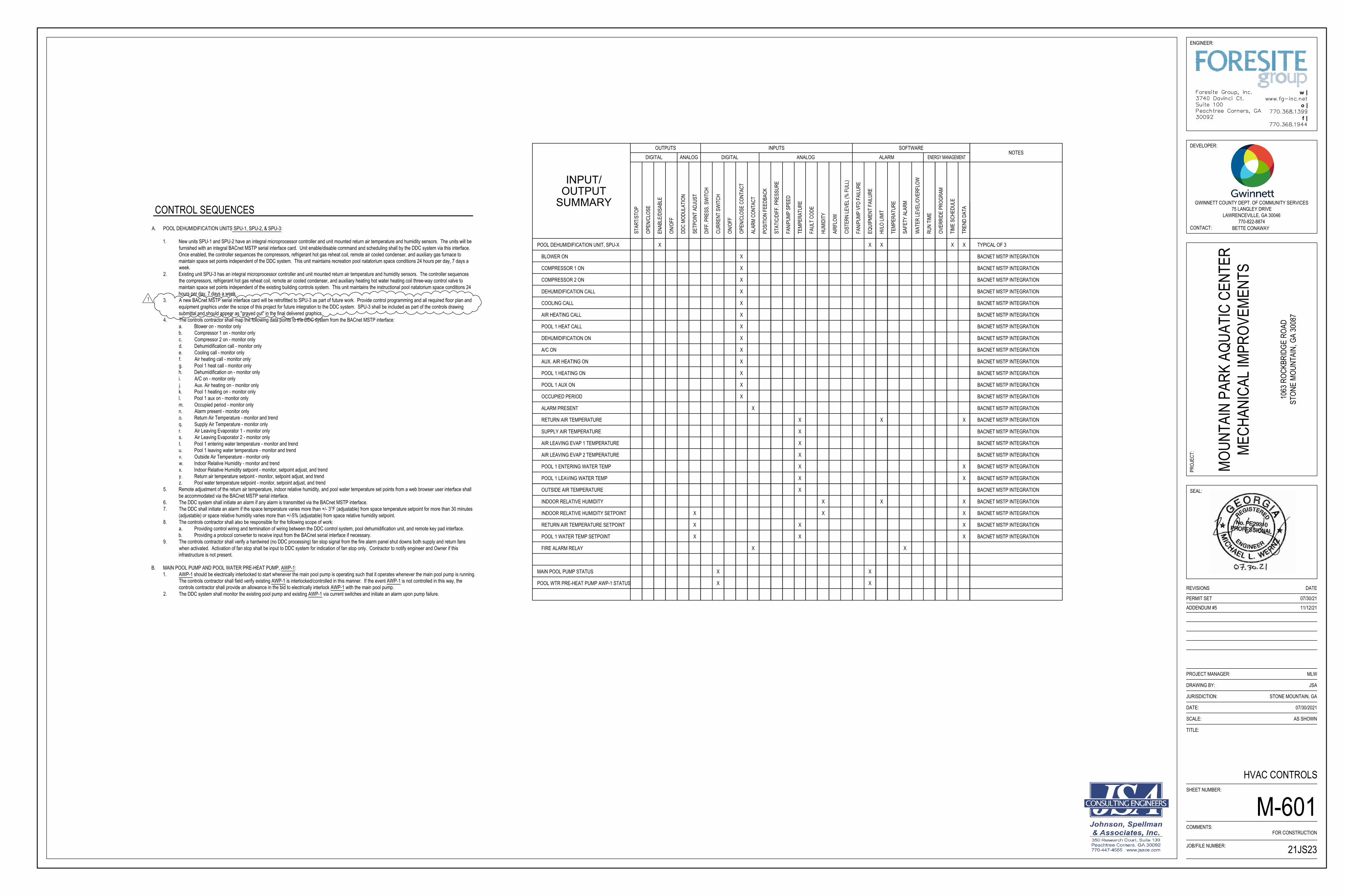
A. POOL DEHUMIDIFICATION UNITS SPU-1, SPU-2, & SPU-3:
1. New units SPU-1 and SPU-2 have an integral microprocessor controller and unit mounted return air temperature and humidity sensors. The units will befurnished with an integral BACnet MSTP serial interface card. Unit enable/disable command and scheduling shall by the DDC system via this interface.Once enabled, the controller sequences the compressors, refrigerant hot gas reheat coil, remote air cooled condenser, and auxiliary gas furnace tomaintain space set points independent of the DDC system. This unit maintains recreation pool natatorium space conditions 24 hours per day, 7 days aweek.
2. Existing unit SPU-3 has an integral microprocessor controller and unit mounted return air temperature and humidity sensors. The controller sequencesthe compressors, refrigerant hot gas reheat coil, remote air cooled condenser, and auxiliary heating hot water heating coil three-way control valve tomaintain space set points independent of the existing building controls system. This unit maintains the instructional pool natatorium space conditions 24hours per day, 7 days a week.
3. A new BACnet MSTP serial interface card will be retrofitted to SPU-3 as part of future work. Provide control programming and all required floor plan andequipment graphics under the scope of this project for future integration to the DDC system. SPU-3 shall be included as part of the controls drawingsubmittal and should appear as "grayed out" in the final delivered graphics.
4. The controls contractor shall map the following data points to the DDC system from the BACnet MSTP interface:a. Blower on - monitor onlyb. Compressor 1 on - monitor onlyc. Compressor 2 on - monitor onlyd. Dehumidification call - monitor onlye. Cooling call - monitor onlyf. Air heating call - monitor onlyg. Pool 1 heat call - monitor onlyh. Dehumidification on - monitor onlyi. A/C on - monitor onlyj. Aux. Air heating on - monitor onlyk. Pool 1 heating on - monitor onlyl. Pool 1 aux on - monitor onlym. Occupied period - monitor onlyn. Alarm present - monitor onlyo. Return Air Temperature - monitor and trendq. Supply Air Temperature - monitor onlyr. Air Leaving Evaporator 1 - monitor onlys. Air Leaving Evaporator 2 - monitor onlyt. Pool 1 entering water temperature - monitor and trendu. Pool 1 leaving water temperature - monitor and trendv. Outside Air Temperature - monitor onlyw. Indoor Relative Humidity - monitor and trendx. Indoor Relative Humidity setpoint - monitor, setpoint adjust, and trendy. Return air temperature setpoint - monitor, setpoint adjust, and trendz. Pool water temperature setpoint - monitor, setpoint adjust, and trend
5. Remote adjustment of the return air temperature, indoor relative humidity, and pool water temperature set points from a web browser user interface shallbe accommodated via the BACnet MSTP serial interface.
6. The DDC system shall initiate an alarm if any alarm is transmitted via the BACnet MSTP interface.7. The DDC shall initiate an alarm if the space temperature varies more than +/- 3°F (adjustable) from space temperature setpoint for more than 30 minutes
(adjustable) or space relative humidity varies more than +/-5% (adjustable) from space relative humidity setpoint.8. The controls contractor shall also be responsible for the following scope of work:
a. Providing control wiring and termination of wiring between the DDC control system, pool dehumidification unit, and remote key pad interface.b. Providing a protocol converter to receive input from the BACnet serial interface if necessary.
9. The controls contractor shall verify a hardwired (no DDC processing) fan stop signal from the fire alarm panel shut downs both supply and return fanswhen activated. Activation of fan stop shall be input to DDC system for indication of fan stop only. Contractor to notify engineer and Owner if this infrastructure is not present.
B. MAIN POOL PUMP AND POOL WATER PRE-HEAT PUMP, AWP-1:1. AWP-1 should be electrically interlocked to start whenever the main pool pump is operating such that it operates whenever the main pool pump is running.
The controls contractor shall field verify existing AWP-1 is interlocked/controlled in this manner. If the event AWP-1 is not controlled in this way, thecontrols contractor shall provide an allowance in the bid to electrically interlock AWP-1 with the main pool pump.
2. The DDC system shall monitor the existing pool pump and existing AWP-1 via current switches and initiate an alarm upon pump failure.
CONTROL SEQUENCES
ENERGY MANAGEMENTDIGITAL
ON/O
FF
INPUT/
SUMMARY
OUTPUT
SETP
OINT
ADJ
UST
ENAB
LE/D
ISAB
LE
DDC
MODU
LATI
ON
STAR
T/ST
OP
DIFF
. PRE
SS. S
WIT
CH
CURR
ENT
SWIT
CH
ON/O
FF
DIGITALOUTPUTS
ANALOG
AIRF
LOW
TEMP
ERAT
URE
FAUL
T CO
DE
POSI
TION
FEE
DBAC
K
ALAR
M CO
NTAC
T
FAN/
PUMP
SPE
ED
STAT
IC/D
IFF.
PRE
SSUR
E
OPEN
/CLO
SE C
ONTA
CT
HUMI
DITY
INPUTSANALOG
RUN
TIME
HI/LO
LIMI
T
TEMP
ERAT
URE
SAFE
TY A
LARM
OVER
RIDE
PRO
GRAM
FAN/
PUMP
VFD
FAI
LURE
EQUI
PMEN
T FA
ILURE
WAT
ER LE
VEL/O
VERF
LOW
TIME
SCH
EDUL
E
SOFTWAREALARM
TREN
D DA
TA
NOTES
OPEN
/CLO
SE
XPOOL DEHUMIDIFICATION UNIT, SPU-X
CIST
ERN
LEVE
L (%
FUL
L)
XCOMPRESSOR 1 ON
COMPRESSOR 2 ON X
XDEHUMIDIFICATION CALL
COOLING CALL X
XAIR HEATING CALL
XPOOL WTR PRE-HEAT PUMP AWP-1 STATUS X
POOL 1 HEAT CALL
DEHUMIDIFICATION ON
X
X
XMAIN POOL PUMP STATUS X
X
BACNET MSTP INTEGRATION
A/C ON
AUX. AIR HEATING ON
POOL 1 AUX ON
OCCUPIED PERIOD
ALARM PRESENT
RETURN AIR TEMPERATURE
SUPPLY AIR TEMPERATURE
AIR LEAVING EVAP 1 TEMPERATURE
X
X
X
X
X
X
X
X
BACNET MSTP INTEGRATION
BACNET MSTP INTEGRATION
BACNET MSTP INTEGRATION
BACNET MSTP INTEGRATION
BACNET MSTP INTEGRATION
BACNET MSTP INTEGRATION
BACNET MSTP INTEGRATION
BACNET MSTP INTEGRATION
BACNET MSTP INTEGRATION
BACNET MSTP INTEGRATION
BACNET MSTP INTEGRATION
BACNET MSTP INTEGRATION
BACNET MSTP INTEGRATION
BACNET MSTP INTEGRATION
BLOWER ON X BACNET MSTP INTEGRATION
X
POOL 1 ENTERING WATER TEMP
POOL 1 LEAVING WATER TEMP
OUTSIDE AIR TEMPERATURE
INDOOR RELATIVE HUMIDITY
INDOOR RELATIVE HUMIDITY SETPOINT X
X
X
X
X
X
X
X X
BACNET MSTP INTEGRATION
BACNET MSTP INTEGRATION
BACNET MSTP INTEGRATION
BACNET MSTP INTEGRATION
BACNET MSTP INTEGRATION
RETURN AIR TEMPERATURE SETPOINT X
POOL 1 WATER TEMP SETPOINT X
FIRE ALARM RELAY X X
BACNET MSTP INTEGRATION
BACNET MSTP INTEGRATION
X
X
X
XX
POOL 1 HEATING ON X BACNET MSTP INTEGRATION
X
X
AIR LEAVING EVAP 2 TEMPERATURE X BACNET MSTP INTEGRATION
X
X
TYPICAL OF 3X
TITLE:
DATE:
JURISDICTION:
DRAWING BY:
PROJECT MANAGER:
SHEET NUMBER:
COMMENTS:
SEAL:
DEVELOPER:
PROJ
ECT:
CONTACT:
DATEREVISIONS
ENGINEER:
SCALE:
JOB/FILE NUMBER:
w |
o |
f |
GWINNETT COUNTY DEPT. OF COMMUNITY SERVICES75 LANGLEY DRIVE
LAWRENCEVILLE, GA 30046770-822-8874
BETTE CONAWAY
MOUN
TAIN
PAR
K AQ
UATI
C CE
NTER
MECH
ANIC
AL IM
PROV
EMEN
TS
1063
ROC
KBRI
DGE
ROAD
STON
E MO
UNTA
IN, G
A 30
087
21JS23
07/30/2021
AS SHOWN
MLW
JSA
STONE MOUNTAIN, GA
FOR CONSTRUCTION
PERMIT SET 07/30/21
HVAC CONTROLS
M-601
11/12/21ADDENDUM #5
AutoCAD SHX Text
1
AutoCAD SHX Text
Foresite Group, Inc. 3740 Davinci Ct. Suite 100 Peachtree Corners, GA 30092
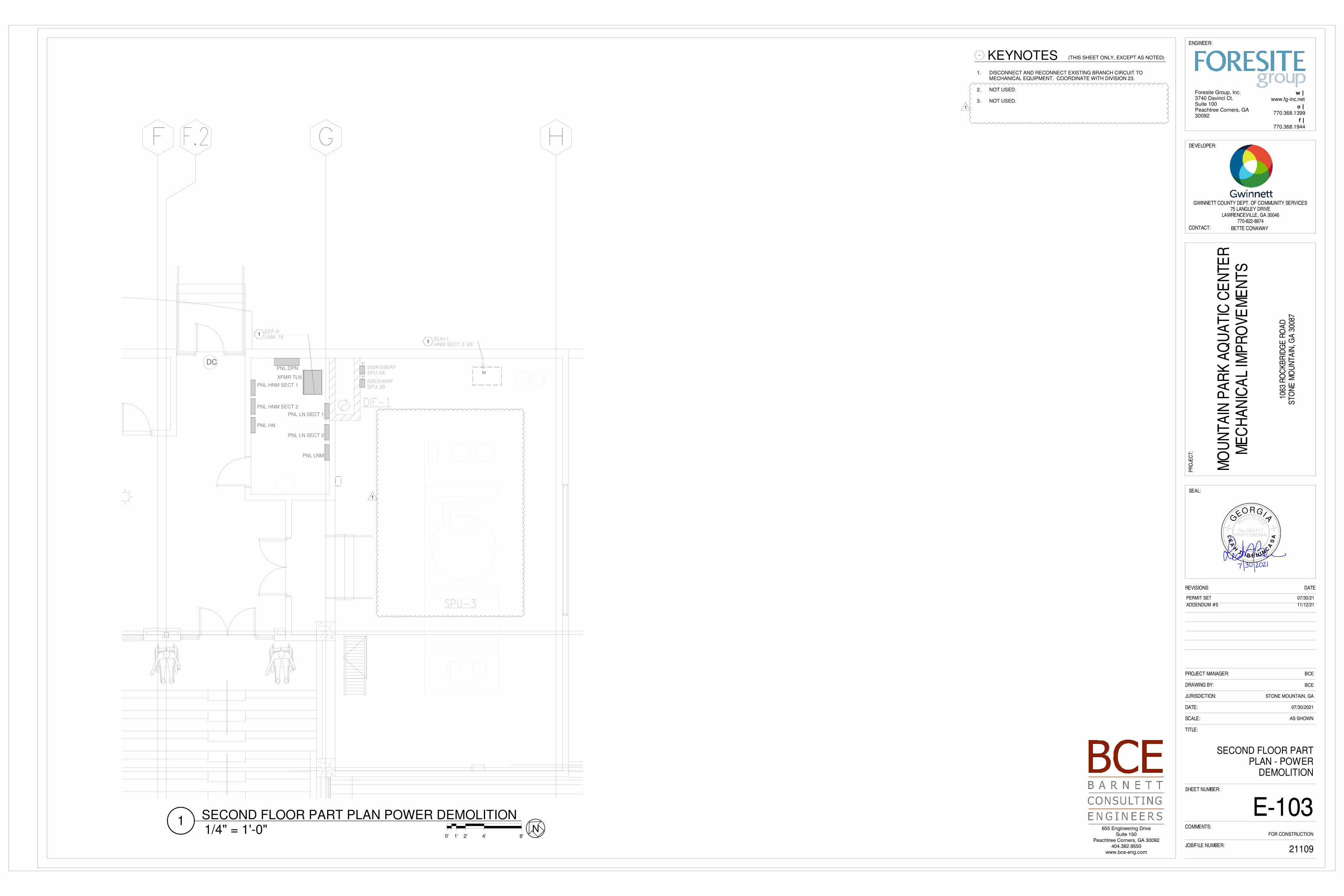
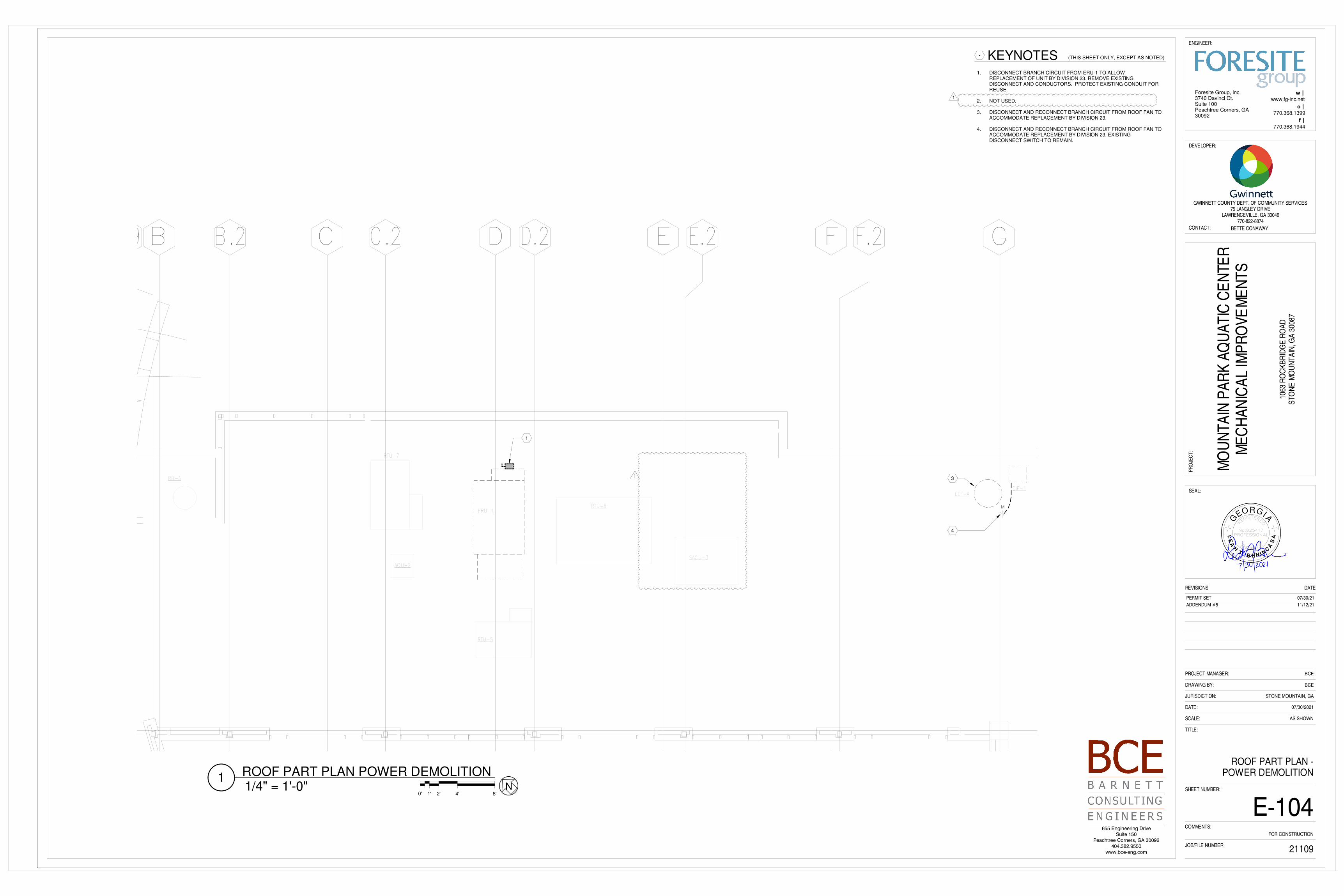
1. DISCONNECT BRANCH CIRCUIT FROM ERU-1 TO ALLOW REPLACEMENT OF UNIT BY DIVISION 23. REMOVE EXISTING DISCONNECT AND CONDUCTORS. PROTECT EXISTING CONDUIT FOR REUSE.
2. NOT USED.
3. DISCONNECT AND RECONNECT BRANCH CIRCUIT FROM ROOF FAN TO ACCOMMODATE REPLACEMENT BY DIVISION 23.
4. DISCONNECT AND RECONNECT BRANCH CIRCUIT FROM ROOF FAN TO ACCOMMODATE REPLACEMENT BY DIVISION 23. EXISTING DISCONNECT SWITCH TO REMAIN.
1. RECONNECT EXISTING BRANCH CIRCUIT TO REPLACEMENT MECHANICAL EQUIPMENT. COORDINATE WITH DIVISION 23.
2. NOT USED.
3. APPROXIMATE LOCATION OF NEW DDC PANEL PROVIDED BY DIVISION 23. PROVIDE 2#12, #12G IN 0.75" CONDUIT. PROVIDE 20A/1P BREAKER IN EXISTING SPACE. COORDINATE EXACT LOCATION AND REQUIREMENTS WITH DIVISION 23.
1. PROVIDE NEW BRANCH CIRCUIT IN EXISTING CONDUIT FOR NEW ERU-1. EXTEND AND CONNECT TO UNIT MOUNTED DISCONNECT. COORDINATE EXACT LOCATION WITH DIVISION 23 AND EQUIPMENT SHOP DRAWINGS.
2. NOT USED.
3. MODIFY EXISTING BRANCH CIRCUIT AS REQUIRED AND RECONNECT TO REPLACEMENT FAN.
4. EXTEND AND CONNECT TO REPLACEMENT FAN. EXISTING DISCONNECT TO REMAIN.
EXISTING PANELBOARD - BRANCH CIRCUITS ARE EXISTING TO REMAIN, UNO.
PANELBOARD "HNM SECT 2"
LOAD CALCULATIONS
PANEL CONNECTED
HNM 489.9
REMOVED LOAD (417.0)ADDED LOAD +444.2CHANGE +27.2
TOTAL HNM 517.1
HNM RATED (800A) 531.8
3-#10, 1-#10G. IN EX C.
EXISTING
EXISTING
EXISTING
EXISTING
PERMIT SET 07/30/21
ADDENDUM #5 11/12/21
1
1
GWINNETT COUNTY, GEORGIA MOUNTAIN PARK AQUATIC CENTER MECHANICAL IMPROVEMENTS BL115-21
Energy Recovery Units 23 7200 - 1
Revised Section 23 7200 Energy Recovery Units
Part 1 General
1.01 Description
A. This section specifies requirements for indoor Energy Recovery Ventilator (ERV) units.
1.02 Related Sections
A. Section 23 0010 General Provisions - HVAC
B. Section 23 0100 Operation and Maintenance of HVAC Systems
C. Section 23 3100 Ductwork
1.03 Submittals
A. See General Conditions for submittal procedure.
B. Provide data on unit performance including, but not limited to, entering and leaving air temperatures, airflow and total static pressure, fan motor horsepower, total and sensible heat recovery.
C. Provide shop drawing showing unit dimensions, weight, electrical requirements,
service access requirements and duct connection sizes and locations.
D. Provide manufacturer’s instructions, indicate installation and support requirements.
E. Provide operation and maintenance procedures; include start-up instructions, assembly drawings and parts list.
1.04 Quality Assurance
A. Unit shall be carry UL label of approval and bear AMCA certified rating seals for air performance.
B. The ERV manufacturer shall provide a one-year warranty minimum on all parts.
Enthalpy wheels shall carry a 5-year warranty.
C. Provide a three-year warranty on the variable frequency drives.
GWINNETT COUNTY, GEORGIA MOUNTAIN PARK AQUATIC CENTER MECHANICAL IMPROVEMENTS BL115-21
Energy Recovery Units 23 7200 - 2
Part 2 Products
NOTE
All references to vendors and "approved manufacturers" are included for description of quality and content of the designated equipment/materials. Equivalent items may be accepted if they meet all standards of quality and purpose for the intended use, as determined by Gwinnett County.
2.01 Energy Recovery Ventilators
A. Energy Recovery Ventilators (ERV) shall be enthalpy-type, air to air heat exchangers utilizing desiccant-type heat wheels. Units shall include motorized heat wheel assembly, outside air supply fan, exhaust fan, supply and exhaust filters, pre- wired single point electrical connection, independent variable frequency drives for outside air and exhaust fans, disconnect switch, integral microprocessor controls, and BACNet MSTP card for interface with building automation system. ERVs shall be outdoor type. ERV shall be rooftop mounted as shown on the drawings. Minimum design efficiency shall be as scheduled.
B. Unit casing shall be constructed of removable, insulated double wall panels. Panels
shall be gasketed where in contact with the unit frame. Module-to-module connections shall have gasketing between metal-to-metal surfaces. Outer wall shall be G90 galvanized steel, minimum 18 Ga. The inner walls shall be solid galvanized steel. The panels shall be insulated with minimum 1" thick foam or fiberglass insulation meeting the requirements of NFPA 90A. Hinged and gasketed access doors shall be provided for supply fan, exhaust fan, filters, VFD/controls compartments. Units shown for rooftop installation shall have weather resistant gasketing and seals and housing shall be suitable for outdoor installations.
1. Dimensional Limitations: It is the design intent to replace existing equipment
with new equipment of the similar physical size. The footprint of the unit casing shall not exceed the shape and dimensions shown on the drawings unless approved by the engineer and Owner.
C. Heat Wheel
1. Provide total energy heat wheel with performance as scheduled. Rotor
performance shall be independently tested in accordance with applicable ASHRAE guidelines (Method 84-91), and rated in accordance with ARI Rating Method 1060.
2. Wheel shall be either polymer media with silica gel desiccant or aluminum
honeycomb construction with molecular sieve desiccant permanently dispersed throughout the matrix structure.
3. Heat wheel shall be easily accessible for inspection, removal and cleaning.
Wheel design shall consist of removable segments for ease of service and/or cleaning.
GWINNETT COUNTY, GEORGIA MOUNTAIN PARK AQUATIC CENTER MECHANICAL IMPROVEMENTS BL115-21
Energy Recovery Units 23 7200 - 3
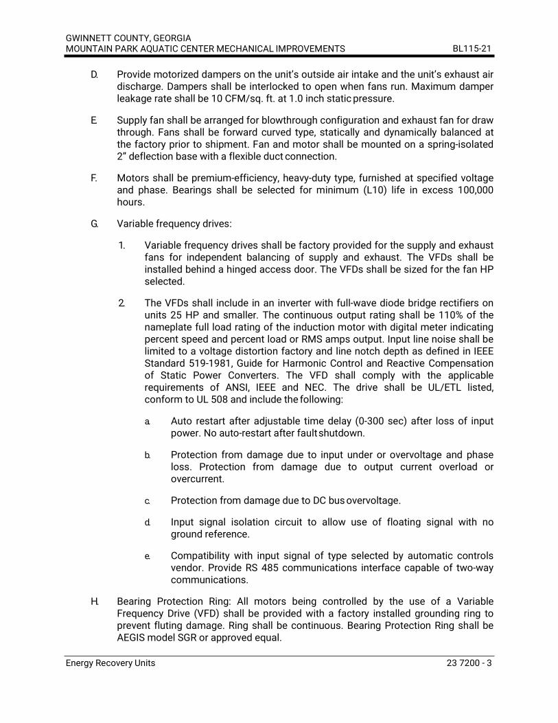
D. Provide motorized dampers on the unit’s outside air intake and the unit’s exhaust air discharge. Dampers shall be interlocked to open when fans run. Maximum damper leakage rate shall be 10 CFM/sq. ft. at 1.0 inch static pressure.
E. Supply fan shall be arranged for blowthrough configuration and exhaust fan for draw
through. Fans shall be forward curved type, statically and dynamically balanced at the factory prior to shipment. Fan and motor shall be mounted on a spring-isolated 2” deflection base with a flexible duct connection.
F. Motors shall be premium-efficiency, heavy-duty type, furnished at specified voltage
and phase. Bearings shall be selected for minimum (L10) life in excess 100,000 hours.
G. Variable frequency drives:
1. Variable frequency drives shall be factory provided for the supply and exhaust
fans for independent balancing of supply and exhaust. The VFDs shall be installed behind a hinged access door. The VFDs shall be sized for the fan HP selected.
2. The VFDs shall include in an inverter with full-wave diode bridge rectifiers on
units 25 HP and smaller. The continuous output rating shall be 110% of the nameplate full load rating of the induction motor with digital meter indicating percent speed and percent load or RMS amps output. Input line noise shall be limited to a voltage distortion factory and line notch depth as defined in IEEE Standard 519-1981, Guide for Harmonic Control and Reactive Compensation of Static Power Converters. The VFD shall comply with the applicable requirements of ANSI, IEEE and NEC. The drive shall be UL/ETL listed, conform to UL 508 and include the following:
a. Auto restart after adjustable time delay (0-300 sec) after loss of input
power. No auto-restart after fault shutdown.
b. Protection from damage due to input under or overvoltage and phase loss. Protection from damage due to output current overload or overcurrent.
c. Protection from damage due to DC bus overvoltage.
d. Input signal isolation circuit to allow use of floating signal with no
ground reference.
e. Compatibility with input signal of type selected by automatic controls vendor. Provide RS 485 communications interface capable of two-way communications.
H. Bearing Protection Ring: All motors being controlled by the use of a Variable
Frequency Drive (VFD) shall be provided with a factory installed grounding ring to prevent fluting damage. Ring shall be continuous. Bearing Protection Ring shall be AEGIS model SGR or approved equal.
GWINNETT COUNTY, GEORGIA MOUNTAIN PARK AQUATIC CENTER MECHANICAL IMPROVEMENTS BL115-21
Energy Recovery Units 23 7200 - 4
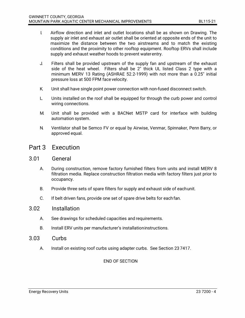
I. Airflow direction and inlet and outlet locations shall be as shown on Drawing. The supply air inlet and exhaust air outlet shall be oriented at opposite ends of the unit to maximize the distance between the two airstreams and to match the existing conditions and the proximity to other rooftop equipment. Rooftop ERVs shall include supply and exhaust weather hoods to prevent water entry.
J. Filters shall be provided upstream of the supply fan and upstream of the exhaust
side of the heat wheel. Filters shall be 2" thick UL listed Class 2 type with a minimum MERV 13 Rating (ASHRAE 52.2-1999) with not more than a 0.25" initial pressure loss at 500 FPM face velocity.
K. Unit shall have single point power connection with non-fused disconnect switch.
L. Units installed on the roof shall be equipped for through the curb power and control
wiring connections.
M. Unit shall be provided with a BACNet MSTP card for interface with building automation system.
N. Ventilator shall be Semco FV or equal by Airwise, Venmar, Spinnaker, Penn Barry, or
approved equal.
Part 3 Execution
3.01 General
A. During construction, remove factory furnished filters from units and install MERV 8 filtration media. Replace construction filtration media with factory filters just prior to occupancy.
B. Provide three sets of spare filters for supply and exhaust side of each unit.
C. If belt driven fans, provide one set of spare drive belts for each fan.
3.02 Installation
A. See drawings for scheduled capacities and requirements.
B. Install ERV units per manufacturer’s installation instructions.
3.03 Curbs
A. Install on existing roof curbs using adapter curbs. See Section 23 7417.
END OF SECTION
GWINNETT COUNTY, GEORGIA MOUNTAIN PARK AQUATIC CENTER MECHANICAL IMPROVEMENTS BL115-21
Pool Dehumidification Unit 23 8419 - 1
Revised Section 23 8419 Pool Dehumidification Units
Part 1 General
1.01 Description
A. This section specifies the pool dehumidification unit requirements.
1.02 Related Sections
A. Section 23 0010 General Provisions HVAC
B. Section 23 0100 Operation and Maintenance of HVAC Systems
C. Section 23 0500 Common Work Results for HVAC
1.03 Submittals
A. See General Conditions for submittal procedure.
B. Provide data on unit performance including, but not limited to, entering and leaving air temperatures, fan airflow and associated total and external static pressure, fan motor horsepower, fan curves and coil capacity.
C. Provide shop drawing showing unit dimensions, weight, electrical requirements,
service access requirements and duct and piping connection sizes and locations.
D. Provide manufacturer’s instructions, indicate installation and support requirements.
E. Provide operation and maintenance procedures; include start-up instructions, assembly drawings and parts list.
1.04 Quality Assurance
A. Fan performance shall be rated in accordance with AMCA 210.
B. Coil performance shall be rated in accordance with ARI 410.
C. Air handling unit shall be assembled in accordance with ARI 430 (when applicable).
D. Sound performance data shall be rated per ARI 260.
E. System shall be ETL listed.
GWINNETT COUNTY, GEORGIA MOUNTAIN PARK AQUATIC CENTER MECHANICAL IMPROVEMENTS BL115-21
Pool Dehumidification Unit 23 8419 - 2
Part 2 Products
NOTE:
All references to vendors and "approved manufacturers" are included for description of quality and content of the designated equipment/materials. Equivalent items may be accepted if they meet all standards of quality and purpose for the intended use, as determined by Gwinnett County.
2.01 Pool Dehumidification Unit
A. Description:
1. Furnish and install where indicated, factory assembled, enclosed swimming pool environmental control / energy recovery system. System shall include compressors, mechanical heat recovery, supply and exhaust fans, outdoor, exhaust and recirculated air dampers, pool water condenser, heat section with gas heating, moisture disposal and complete solid state logic control system, factory installed and wired in a single unit enclosure. System shall be configured for installation on slab on grade outside the building.
2. The unit shall be specifically designed, manufactured and tested for enclosed
swimming pool duty. Field assembled or modified standard commercial grade equipment is not acceptable. Complete unit shall be suitable for indoor or outdoor weatherproof mounting.
3. The complete unit shall be listed by an industry recognized, third-party, safety
code agency under the title of “Special Purpose Air Conditioners” and carry the appropriate label.
4. Manufacturer shall have a minimum of five plus year’s prior experience
making similar equipment as described in this specification.
B. Intent: It is the intent of this Section of the specifications to provide a complete, operable, adjusted natatorium dehumidification system as shown and scheduled on the plans.
C. Basis of Design: Units shall be PoolPak International or approved equal.
D. Unit Casing:
1. All panels and structural steel members shall be of G-90 galvanized steel or
galvalume, treated and painted prior to assembly to provide a chlorine and pool chemical resistant finish. The paint shall be plastic epoxy-based powder coating, applied 0.003 inch (2-3 mils) thick, and baked and bonded at 420 degrees F until it forms a hard vinyl textured surface.
GWINNETT COUNTY, GEORGIA MOUNTAIN PARK AQUATIC CENTER MECHANICAL IMPROVEMENTS BL115-21
Pool Dehumidification Unit 23 8419 - 3
2. Structural steel frame shall be 3/16-inch steel channel base with 12-gauge
steel cross bracing. Vertical support posts for removable panels shall be formed from 18 gauge-galvanized steel and powder coat painted. All nuts, bolts and lock washers in a corrosive atmosphere shall be Cadmium plated. All sheet metal screws shall be Empigard coated galvanized steel, or approved equal.
3. Double wall panels shall be formed with 20 gauge-galvanized steel and floors
shall be 16 gauge. Access panels shall be secured by two or more tool operated latches. All side panels shall be insulated with minimum two-inch duct liner insulation. The insulation shall be approved for 350 degrees F operating temperature. The fire resistance rating shall conform to NFPA Standard 90A and 90B. The thermal conductivity shall not exceed .29 BTU/hr/F/sq. ft/in at 75 degrees F. All seams shall be bolted and sealed to prevent leaks. The roof shall be gasketed and secured to frame with Empigard coated galvanized steel screws. All nuts, bolts and lock washers exposed to the natatorium air shall be Cadmium plated. All sheet metal screws exposed to the natatorium air shall be Empigard coated galvanized steel, or approved equal.
4. Compressors, pool water condenser, and controls, including solenoid valves,
expansion valves and refrigerant sight glasses shall be located in compartments isolated from unit air stream to allow for ease of maintenance and to provide protection from the corrosive atmosphere.
5. Hinged Access Doors (Factory Standard) shall be provided at the openings for Compressor(s), Air Filters, Electrical Panel, Blowers, Motors, and Drives. Doors shall be double-wall, insulated, mounted on multiple stainless steel piano hinge, secured with two or more tool-operated latches and sealed against a rigid steel frame with hollow-bulb rubber gasket material. Hinged access doors are required on all outdoor installations.
6. Double Wall Panels shall be provided for the entire unit wall and roof structure.
7. Insulation shall be fiberglass, 2” thick. Interior liner shall be 20-gauge G90
galvanized steel with baked epoxy powder coat finish, all sides.
8. Dimensional Limitations: It is the design intent to replace existing equipment with new equipment of the similar physical size. The footprint of the unit casing shall not exceed the dimensions shown on the drawings unless approved by the engineer and Owner.
9. Connections: Provide power, natural gas, and pool condenser water
connections in locations that match existing units being replaced.
GWINNETT COUNTY, GEORGIA MOUNTAIN PARK AQUATIC CENTER MECHANICAL IMPROVEMENTS BL115-21
Pool Dehumidification Unit 23 8419 - 4
E. Compressor:
1. The dehumidifier shall utilize heavy duty scroll compressors with a total of 2 stages dehumidifier with suction gas cooled motors suitable for R-410A refrigerant. Compressors shall be equipped with motor overload protection, large capacity oil sump with oil level sight glass and easily removable external crankcase heaters. Liquid refrigerant controls shall be incorporated for liquid migration protection. All components shall be located outside of airstream.
2. Capacity control shall be microprocessor controlled by staging compressors
allowing reduced load starting and variable load operation. Capacity control through hot gas by-pass is not permissible.
F. Pool Water Condenser:
1. The internal pool water condenser shall be capable of rejecting heat recovered
from the compressor and the evaporator. Refer to the equipment schedule for required MBH capacity of the pool water condenser.
2. Pool water condenser shall be counter flow, tube-in-tube type. Waterside shall
be Type L, cupro-nickel. Pool water condenser shall be insulated with minimum 2-inch closed cell foam. For units located outdoors, the pool water condenser shall be equipped with self-regulating electric heat tape for freeze protection.
a. Pool water condenser shall be double wall, vented with removable plugs
for inspection and cleaning.
3. Pool water heating is controlled by a refrigerant solenoid valve that directs hot refrigerant gas into the pool water condenser as a response from the control system. Water circuit shall be supplied with schedule 80 CPVC pipe stub-outs.
G. Evaporator Coil:
1. Coils shall be fully dipped and coated with a polyester/enamel coating for maximum corrosion protection. Fins shall be aluminum, tubes shall be copper, casings and end plates shall be galvanized.
2. All tubes shall be expanded into fin collars. All joints shall be brazed. The coil
shall be tested to 320 PSIG while submerged in water. All brazing shall be done with nitrogen gas inside tubes to give clean internal surfaces. The coil shall be dried and sealed. Inside of tubes shall be commercially free of oxides and foreign matter.
3. The coil shall be sectioned to provide proportional air-to-refrigerant latent and
sensible heat removal capacity. This capacity modulation shall be accomplished by utilizing multiple thermal expansion valves (TXV) for the evaporator. Each TXV shall be equipped with a refrigerant flow control solenoid valve and refrigerant sight glass.
GWINNETT COUNTY, GEORGIA MOUNTAIN PARK AQUATIC CENTER MECHANICAL IMPROVEMENTS BL115-21
Pool Dehumidification Unit 23 8419 - 5
H. Condenser Coil (Air Reheat Coil):
1. Condenser coil shall be capable of rejecting all the heat (100%) recovered
from the compressor and the evaporator. Refer to equipment schedule for required MBH of reheat coil capacity.
2. Coils shall be fully dipped and coated with a polyester/enamel coating for
maximum corrosion protection. Fins shall be aluminum, tubes shall be copper, casings and end plates shall be galvanized.
3. All tubes shall be expanded into fin collars. All joints shall be brazed. The coil
shall be tested to 320 PSIG while submerged in water. All brazing shall be done with nitrogen gas inside tubes to give clean internal surfaces. The coil shall be dried and sealed. Inside of tubes shall be commercially free of oxides and foreign matter.
4. All tubes shall be expanded into fin collars. All joints shall be brazed. The coil
shall be tested to 400 PSIG while submerged in water. All brazing shall be done with nitrogen gas inside tubes to give clean internal surfaces.
I. Packaged Indirect-Fired Natural Gas Duct Furnace Module:
1. Module shall be sized to meet the scheduled heating capacity.
2. Furnace shall have modulating (0-10V) auxiliary air heat control.
3. The duct furnace module shall be a natural gas indirect-fired type using spark
ignition with a heating capacity as shown in this submittal and is installed in a 'blow through' configuration downstream from the blower. The heat exchanger tubes are constructed of formed and welded 16-gauge series 409 stainless steel suitable for installation downstream of the cooling coil and satisfactory for air inlet temperatures below 40 °F. The burner is the power firing type and incorporates a primary combustion air blower and spark ignition transformer.
4. Standard controls shall include a modulating gas valve, intermittent spark ignition, overheat control, rollout flame supervision, combustion air flow proving switch, positive burner safety switch, pilot cock, main gas cock with 100% shut off, adjustable main and pilot pressure regulators.
5. The natural gas duct furnace module shall be an ETL recognized component.
The gas train shall be complete with all controls factory mounted to comply with requirements of ETL. The gas train is complete with a modulating main gas valve and is ready for connection to a natural gas supply with pressure between 7 in and 14 in WC.
6. The complete system shall be test-fired and preliminary adjustments made
prior to leaving the factory.
J. The evaporator and reheat coils shall be protected with a 2” thick MERV 13 non- metallic filters in a slid in or face loading rack. The outside air intake shall be equipped with 2” MERV 8 filters.
GWINNETT COUNTY, GEORGIA MOUNTAIN PARK AQUATIC CENTER MECHANICAL IMPROVEMENTS BL115-21
Pool Dehumidification Unit 23 8419 - 6
K. OA Intake: Shall be integral to the unit and physically located downstream of the
evaporator and reheat coils. The damper motors shall have NEMA 4 housing and auto close on power failure.
L. Dampers: Dampers shall be parallel blade, less than 1% leakage, neoprene tipped,
anodized aluminum air foil cross section dampers. Each damper section shall be operated by a separate motor factory mounted and wired into unit control panel and be capable of modulating the dampers from 0% to 100%.
M. Fans (Blowers): The units shall be factory equipped with all required fans. The fans
shall be sized per the airflow and external static pressure resulting in the horsepower shown on the equipment schedule. Fans shall be balanced to ensure room negative pressure in the natatorium per the scheduled conditions. These fans shall be direct driven SWSI plenum or vane axial type with multiblade wheels. Construction shall be galvanized steel, painted and baked with an epoxy coating providing a chlorine and pool chemistry resistant finish. The fans shall be dynamically and statically balanced and tested on the shafts. Fan bearings shall be grease lubricated, self-aligning ball bearings selected for 200,000 hours average life.
N. Fan (Blower) Motors: Fan motor shall be premium efficiency totally enclosed fan
cooled, TEFC, with Class F insulation, pre-lubricated ball bearings and shall be mounted on an adjustable base. Motor efficiency shall comply with EPACT-92 requirements as a minimum. Motor to be U.L. listed. Fan motor shall be provided with a factory mounted and wired motor starter protector with an adjustable thermal overload and magnetic short circuit protection. The use of open drip-proof (ODP) motors is not acceptable.
O. Supply Air Fan:
1. The unit shall be equipped with an integral supply air system. A supply air fan
capable of providing the scheduled amount of air shall be located in the unit as required. The fan shall operate continuously.
2. Fans shall be direct driven SWSI plenum style design.
3. Fan rack shall be equipped with 1” deflection spring isolators.
P. Exhaust Air Fan:
1. The unit shall be equipped with an integral exhaust air system. A fan capable of exhausting the specified amount of air shall be located in the return air plenum.
2. Fans shall be vane axial design.
GWINNETT COUNTY, GEORGIA MOUNTAIN PARK AQUATIC CENTER MECHANICAL IMPROVEMENTS BL115-21
Pool Dehumidification Unit 23 8419 - 7
Q. Drain Pan: The floor of each airside section shall be constructed of aluminum and powder coat painted with a protective coating providing a chlorine and pool chemistry resistant finish. The floor sections shall be fully insulated. The floor sections under condensate producing coils shall be sloped toward the drains and piped to a common drain accessible from either side of the unit. All drain lines within the unit shall be insulated with minimum 3/4-inch closed cell foam with self-regulating electric heat tape for freeze protection.
R. Refrigeration Circuit: The refrigeration system shall include a replaceable core liquid
line filter dryer, liquid receiver, thermostatic expansion valves, liquid line solenoid valves, two manual valves to isolate filter drier for fast drier core replacement and manual valves to isolate the liquid receiver. Suction lines shall be fully insulated with closed cell foam insulation. High and low-pressure controls and refrigeration service access valves shall be located in a compartment outside of the air stream.
S. Electrical Connections: Three Point Power Connections: The unit shall be equipped
with appropriately sized factory mounted motor starter protectors, circuit breakers, and a terminal block for three-point (compressors, the integral fluid cooler, and the rest {fans and controls}) field connection of power wiring to the electrical compartment matching the equipment being replaced. The terminal blocks shall be suitable for copper conductors only. All disconnect switches shall be wall mounted and installed by Division 26.
T. Compartment Light: A grounded, 120 VAC, GFCI protected, NEMA 4 switch and
guarded lights shall be provided inside the dehumidifier for service and maintenance convenience.
U. Dirty Filter Indicator Lights
1. Unit shall be equipped with sensors to detect when the pressure drop through
the return air filters indicates the filters are dirty. Pressure drop can be set by user. When the pressure drop is greater than the preset limit, an indicator lamp, visible on the outside of the dehumidifier , is illuminated.
V. Rainhoods:
1. Unit shall be equipped with a rainhood and bird screen for both the outside air
and exhaust air dampers.
2. Rainhoods shall be painted the same as the dehumidifier casing.
W. Operating & Safety Controls:
1. Each unit shall be provided with a complete operating and safety logic control system. The control system shall shut down the compressor in case of high refrigerant pressure, low refrigerant pressure, and / or high motor current conditions. The complete unit (fans & compressor) shall be shut down to protect the motors if power line abnormalities occur.
2. Operating and safety control system shall include all relays, motor controllers,
sensors and switches necessary to operate complete unit.
GWINNETT COUNTY, GEORGIA MOUNTAIN PARK AQUATIC CENTER MECHANICAL IMPROVEMENTS BL115-21
Pool Dehumidification Unit 23 8419 - 8
X. Microprocessor Controller:
1. The controller shall be microprocessor based and the following functions / set points shall be programmable at the panel:
a. Space Dry Bulb Temperature
b. Space Relative Humidity
c. Pool Water Temperature
d. Occupied/Unoccupied Schedule
2. The following readouts and / or annunciation lights shall be provided on the
unit mounted 4 line 20 character backlit LCD display:
a. Power On
b. Space Dry Bulb Temperature
c. Pool Water Temperature
d. Pool Water Flow
e. Outside Air Dry Bulb Temperature
f. Outside Air Relative Humidity
g. Supply Air Dry Bulb Temperature
h. Compressor Circuit Fault
i. Compressors in Pump down
j. First Stage of Compressor On
k. Second Stage of Compressor On (if so equipped)
l. Third Stage of Compressor On (if so equipped)
m. Fourth stage of Compressor On (if so equipped)
n. Unit in Air Heating Mode
o. Unit in Dehumidifying Mode
p. Auxiliary Air Heating Coil On
q. Pool Water Heating On
r. Time of Day / Date / Day of Week
s. Supply Fan Current
GWINNETT COUNTY, GEORGIA MOUNTAIN PARK AQUATIC CENTER MECHANICAL IMPROVEMENTS BL115-21
Pool Dehumidification Unit 23 8419 - 9
t. Return Fan Current
u. Compressor Current
3. Control panel shall be integral to the unit and located in a separate compartment isolated from airflow. Dry contacts shall be provided for alarm and fan interlock. Power block terminals shall be provided for different wire size connections. All wires shall be numbered and color-coded for ease of trouble-shooting. The compressor(s) shall be equipped with motor starter protectors for Single Point Power and shall have an anti-recycle timer to prevent short cycling. The blower motors shall be equipped with motor starter protectors, including adjustable thermal overloads, and magnetic short circuit protection.
4. The memory of the microprocessor control panel shall have a fault code
history log. This fault code history log shall record the last 50 fault codes in the order of their occurrence. Each fault code shall be recorded along with the date and time it occurred and the value of the critical system parameters at the time of the fault. This fault code history log shall be accessible at the unit controller display and at the standard Remote Interface Unit (RIU).
5. The controls shall continuously monitor the 3-phase power lines for abnormal
conditions including: high voltage, low voltage, phase unbalance, phase reversal, and phase loss, even when regenerated voltage is present. The device consists of a solid-state voltage and phase-angle sensing circuit driving an electromechanical relay. A fault condition shall de-energize the relay; when the fault is corrected the device shall automatically reset. Fault conditions are logged and can be read from the display on the phase monitor.
6. This fault code history log shall be accessible at the unit controller display and
at the standard Remote Interface Unit (RIU).
Y. Control Sensors:
1. The unit shall be provided with the following factory mounted and wired control sensors:
a. Space Dry Bulb Temperature
b. Space Relative Humidity
c. Air-Leaving-Evaporator Dry Bulb Temperature
d. Air-Leaving-Evaporator Relative Humidity
e. Pool Water Temperature
f. Supply Air Dry Bulb Temperature
g. Compressor Motor Current
h. Supply Fan Motor Current
GWINNETT COUNTY, GEORGIA MOUNTAIN PARK AQUATIC CENTER MECHANICAL IMPROVEMENTS BL115-21
Pool Dehumidification Unit 23 8419 - 10
i. Return Fan Motor Current
2. The unit shall be delivered with the following factory supplied sensors to be installed in the field by the mechanical contractor:
a. Outside Air Dry Bulb Temperature
b. Outside Air Relative Humidity
Z. Sequence of Operation:
1. All operating and logic controls shall be factory mounted and wired in the unit.
Control sequences shall be designed specifically to control swimming pool environmental conditions.
2. Control system shall provide full modulation of heat recovery / heating system
by proportional control of dry bulb temperature, relative humidity, cold-wall surface condensation prevention humidity reset and ventilation air volume.
3. Controls shall automatically operate heating, dehumidification and heat
recovery system in response to greatest requirement and adjust unit outputs to maintain building conditions. Unit and controls shall be capable of providing full or partial heating capacity to either air or water. Controls shall be capable of proportional control of heating and dehumidification by loading stages of compressor capacity as necessary. As building requirements are satisfied, unit shall unload, and shut off compressors.
4. Unit shall provide the following functions:
a. Ventilation Mode: Provide outdoor ventilation air to satisfy minimum
ventilation air requirements per ASHRAE 62-04 Ventilation Code.
b. Heating, Cooling and Dehumidification Economiser Mode: Provide outdoor air as a function of indoor and outdoor conditions. The economiser shall operate in the space heating, space cooling, space heating and dehumidification or space cooling and dehumidification modes.
c. Exhaust Mode: Each unit shall have an exhaust mode to partially
ventilate the natatorium at specified airflow. The exhaust mode shall be programmable by the owner as needed. Unit controls shall control the supply and exhaust air fan systems and open the outdoor air and exhaust air dampers for a programmed time interval for automatic operation.
GWINNETT COUNTY, GEORGIA MOUNTAIN PARK AQUATIC CENTER MECHANICAL IMPROVEMENTS BL115-21
Pool Dehumidification Unit 23 8419 - 11
d. Purge Mode: Each unit shall have a purge cycle to fully ventilate the natatorium at 100% airflow specified for the supply fan. The exhaust/ purge cycle shall be programmable by the owner as needed to ventilate the natatorium after shocking of the pool has been performed. Unit controls shall control the purge air fan systems and open the outdoor air and exhaust air dampers for a programmed time interval for automatic operation. During purge mode, the compressors are deactivated.
e. Occupied / Unoccupied Control Mode: Microprocessor-based, 7-day, 24-
hour operation controlling the occupied/ unoccupied mode operation during heating season. During unoccupied times the outside air and exhaust dampers shall be closed to minimize the air-heating load
f. Space Heating:
1) As the return air (space) temperature drops below set-point, the
first stage of refrigeration is activated. The PoolPak will remove the latent and sensible heat in the return air as it passes through the evaporator. A portion of the cold air off the evaporator is exhausted from the mixing box to allow the ventilation air to be introduced into the space. The recovered latent, sensible and compressor heat are absorbed by the refrigeration system. This heat is put back into the supply air stream at the condenser/reheat coil which is down-stream of the outside air intake.
2) As the space temperature continues to drop, the subsequent stages of the refrigeration system are activated and shall continue to heat the natatorium space through full proportional control of space dry bulb temperature by staging compressor loading of unit capacity, with humidity override.
3) The last stage of heat shall be an auxiliary natural gas duct
furnace that is activated via the PoolPak’s control system. The PoolPak control system shall modulate the gas valve via 0-10 V signal to the furnace controller.
g. Economiser Mode Option: If outdoor air is dry and/or cool, it could be
used to dehumidify and/or cool the premise. In this case, on a call for Dehumidification or Air Conditioning mode(s), control system shall increase exhaust fan(s) speed signal to direct more stale return air outside and bring in more outdoor (dry/cool) air in, thus reducing supply air humidity and/or temperature (as needed).
h. Pool Water Heating: If the space temperature is at or above set point
and the pool water temperature is below the set point; hot gas is directed to the pool water condenser when the compressor is running. At other times the pool water requires heat, the PoolPak activates the main pool water heater. Specified amount of heat Full heat of rejection is provided by the pool water condenser.
GWINNETT COUNTY, GEORGIA MOUNTAIN PARK AQUATIC CENTER MECHANICAL IMPROVEMENTS BL115-21
Pool Dehumidification Unit 23 8419 - 12
i. Humidity Control:
1) The economiser is activated if dehumidification is required and all of the following occur:
a) Air and water temperatures are satisfied
b) Absolute humidity of the outside air is lower than the
absolute humidity of the pool room air.
c) Outside air temperature will not adversely affect the pool room air temperature.
2) When outside air cannot be used for dehumidification, then full
proportional control of humidity is done by staging unit capacity. Humidity controller energizes the compressor and directs hot gas to the air reheat condenser if space needs heating or pool water condenser if pool water temperature is below set point.
3) If dehumidification is required and the air and water temperatures
are satisfied and the outside air cannot be used to dehumidify the pool room, then the hot gas is directed to the air-cooled or water- cooled condenser.
j. DX Cooling with Integral Fluid Cooler: On a call for space cooling, the refrigeration system is energized. The return air passing through the unit’s evaporator coil is cooled. The cooled air is delivered to the natatorium by the supply fan. The heat recovered by the evaporator and compressor is directed to the fluid cooler.
AA. BACnet MS/TP: The dehumidifier control panel shall be capable of direct connection
BACnet MS/TP-based Building Automation System. With proper connection to the RS-485 network, the dehumidifier shall appear as a native BACnet device.
BB. Integral Air-cooled Fluid Cooler
1. Each dehumidifier shall be equipped with an integral fluid cooler. All
interconnecting piping shall be factory installed.
2. Unit cabinet is constructed of galvanized sheet metal. All panels are removable. Condenser coils are copper tube with aluminum plate fins, galvanized steel frames and tube sheets. Fan cycling operated by staging condenser fans in response to head pressure down to 20F. Fused fan motor contactors are mounted inside the unit.
3. Dimensional Limitations: It is the design intent to replace existing equipment
with new equipment of the similar physical size. The footprint of the unit casing shall not exceed the dimensions shown on the drawings unless approved by the engineer and Owner.
4. The cooler shall be factory mounted on the end of the unit and provided with
glycol solution for field mixing.
GWINNETT COUNTY, GEORGIA MOUNTAIN PARK AQUATIC CENTER MECHANICAL IMPROVEMENTS BL115-21
Pool Dehumidification Unit 23 8419 - 13
Part 3 Execution
3.01 General
A. During construction, remove factory furnished filters from units and install MERV 8 filtration media. Replace construction filtration media with factory filters just prior to occupancy.
B. Provide three sets of spare filters for each unit.
C. Adjust vibration isolators in fan section after operation of equipment begins. Secure
isolators to supports when finally set.
D. Bolt unit anchors to slab or pad at anchor points.
E. Provide airtight seal at electrical connection to unit.
3.02 Functional Factory Test and Verification
A. The completed unit shall be completely tested for functionality in the factory before shipment.
B. The functional test shall consist of an in-unit test of the controller, inputs, outputs, safeties and the basic sequence of operation. Also, part of the functional test will be verification of the operation of compressor(s), fan(s), and associated electrical components, and if furnished, gas furnaces controls and/or the valve actuators for coils. The functional test shall not be construed as a performance or capacity test.
C. Each unit will have a record of the test certificate prepared documenting the unit
serial number which shall be maintained at the factory. Testing of field installed components or the sequence of operation is not a substitute for factory testing.
D. A copy of the functional test report shall be maintained on file and can be furnished
upon request.
3.03 Installation
A. Comply with manufacturer's printed instructions except where more stringent requirements are shown or specified, and except where manufacturer's technical representative directs otherwise.
B. Install unit where shown on drawings. Provide three feet clearance around sides and
four feet around compressor compartment of unit for airflow and service. Provide a means for access to all sides of the unit.
3.04 Start-Up, Owner Training, and Warranty
A. All units shall be thoroughly cleaned by the installing contractor in accordance with the manufacturer's instructions prior to being placed into service.
GWINNETT COUNTY, GEORGIA MOUNTAIN PARK AQUATIC CENTER MECHANICAL IMPROVEMENTS BL115-21
Pool Dehumidification Unit 23 8419 - 14
B. Start-up service shall be provided by the equipment manufacturer's authorized
representative and shall include complete testing of all controls and unit operation. The agency responsible for start-up shall record the refrigeration pressures and electrical operating data. Copies of this data are to be supplied to the owner.
C. A complete operating and maintenance manual, including wiring diagrams, start-up
and operating sequence and material list shall be provided to the owner. The owner shall be provided with complete instruction of operating and maintenance procedures.
D. Manufacturer shall provide owner with minimum (2) hours on-site training for owner’
staff by factory service personnel in the operation and maintenance requirements of this unit. This training session shall be at time of factory start up.
E. Manufacturer shall provide two-year parts and labor warranty on the entire unit.
F. Drive Line Warranty
1. A manufacturer’s three-year extended driveline parts and labor warranty (total
of 5 years) shall be provided on the:
a. Dampers
b. Damper motors
c. Compressor Motor Contactor (or Protector)
d. Return Fan Motor
e. Return Fan Motor Starter (or Protector)
f. Supply Fan Motor
g. Supply Fan Motor Starter (or Protector)
h. Pool Water Condenser Solenoid Valves & Coils
i. Liquid Expansion Solenoid Valves & Coils
j. Air Condenser Solenoid Valves & Coils
k. Blowers, Wheels & Housings
2. A manufacturer’s three-year extended parts and labor warranty (total of 5 years) shall be provided on the compressor.
G. Coil Warranty: A eight-year extended parts warranty (total of 10 years) shall be
provided on the evaporator and condenser coils. These warranties are contingent on proper maintenance of pool water chemistry including: pH between 7.2 and 7.6; free chlorine not exceeding 3.0 ppm; and Combined Chlorine not to exceed 0.2 ppm.
GWINNETT COUNTY, GEORGIA MOUNTAIN PARK AQUATIC CENTER MECHANICAL IMPROVEMENTS BL115-21
Pool Dehumidification Unit 23 8419 - 15
H. Protective Wrapping for Shipping and /or Storage: Provide a heat shrunk heavy plastic protective wrapping around the top and sides of the unit to protect the unit from weather or road dirt while being shipped and / or stored. The wrapping shall be draped over the unit and secured at the base with cordage suitable to prevent wind from lifting the wrap and creating abrasion. Corners shall have caps to prevent punching of the wrap. Openings for ducts, etc. shall be covered under the wrap with a rigid material to prevent damage to the wrap. Wrap shall be taped at the joints with a similar material and heat shrunk to a uniform tension. Other methods such as stretch film or tarps are not acceptable alternatives.