57
Landis+Gyr Inc. Implementation of DNP V3.00 Protocol Level 2 & 3 Document Number MKB-524011500 Revision E

Landis+Gyr Inc.
Implementation of DNP V3.00 Protocol Level 2 & 3 Document Number MKB-524011500 Revision E

Implementation of DNP V3.00 Protocol Level 2 & 3 Document Number MKB-524011500 Revision E
CONFIDENTIAL
This material is the property of Landis+Gyr Inc. To be returned upon request. Not to be copied, reproduced, loaned, or otherwise disposed of directly or indirectly. It contains confidential proprietary information to be used only for reference, installation, and maintenance of equipment or other dealings with this company. Further use, without written permission first obtained, is not authorized.

ii
Information in this document is subject to change without notice. No part of this document may be reproduced or transmitted in any form or by any means, electronic or mechanical, for any purpose without the express written permission of Landis+Gyr Inc.
© 1997 Landis+Gyr Inc.
All rights reserved.
For further information, contact:
Landis+Gyr Inc. Tel: 765-742-1001
Meter Division Toll Free: 800-777-2774
2800 Duncan Road Fax: 765-429-1326
Lafayette, In 47904-5012 USA Website: www.LandisGyr.us

iii

iv
Document History
Title: Implementation of DNP V3.00 Protocol Level 2 & 3
Document Number: MKB-524011300
Revision Level
Date Issued
Description of Revision
Original 5/24/01 Initial issue.
Revision A
Revision B
Revision C
Revision D
Revision E
8/02/01
7/08/02
11/18/02
3/12/03
5/27/03
Add set-up information on all protocol board jumpers
Table 50 set-up and defaults
Additional error code information Updated Device Profile
Removed unsolicited responses for certification
Added DNP Certification Label and changed Siemens to Landis+Gyr.

v
TABLE OF CONTENTS
1 Communications ........................................................................................... 1 1.1 Baud Rate ..........................................................................................................1 1.2 UART setup .......................................................................................................1 1.3 Data Link Layer Services ...................................................................................1
1.3.1 Data Link Confirmations ............................................................................................ 1 1.3.2 Data Link Retries ....................................................................................................... 1 1.3.3 Collision Avoidance ................................................................................................... 1 1.3.4 Data Link Layer Transport Receive Buffer ................................................................ 2 1.3.5 Data Link Layer Transport Transmit Buffer ............................................................... 2
1.4 Time Synchronization.........................................................................................2 2 Data Point Mapping ...................................................................................... 3
2.1 Binary Inputs ......................................................................................................3 2.1.1 Error Status Bits......................................................................................................... 3 2.1.2 Status Input Bits......................................................................................................... 3 2.1.3 Relay Output Status................................................................................................... 3
2.2 Binary Outputs ...................................................................................................4 2.3 Analog Inputs .....................................................................................................4 2.4 Analog Outputs ..................................................................................................5 2.5 Binary Counter Inputs ........................................................................................5
2.5.1 Register Data ............................................................................................................. 5 3 Event Storage............................................................................................... 6
3.1 Binary Input Change Events ..............................................................................6 3.2 Analog Input Change Events .............................................................................6
3.2.1 Analog Dead Band..................................................................................................... 6 3.3 Binary Counter Change Events..........................................................................7
4 Object and Variation Support ........................................................................ 8 4.1 Object 1 – Binary Input Object (Static) ...............................................................8 4.2 Object 2 – Binary Input Change Object (Event) .................................................8 4.3 Object 10 – Binary Output Object (Static) ..........................................................8 4.4 Object 12 – Control Block Object (Static)...........................................................8 4.5 Object 20 – Binary Counter Object (Static) ........................................................8 4.6 Object 21 – Frozen Counter Object (Frozen Static) ...........................................8 4.7 Object 22 – Counter Change Event Object (Event)............................................9 4.8 Object 23 – Frozen Counter Event Object (Frozen Event) .................................9 4.9 Object 30 – Analog Input Object (Static) ............................................................9 4.10 Object 31 – Frozen Analog input Object (Frozen Static).................................9 4.11 Object 32 – Analog Change Event Object (Event) ..........................................9 4.12 Object 33 – Frozen Analog Event Object (Frozen Event) .............................10 4.13 Object 34 – Analog Event Deadband Object ................................................10

vi
4.14 Object 40 – Analog Output Status Object (Static) .........................................10 4.15 Object 41 – Analog Output Block Object (Static) ..........................................10 4.16 Object 50 – Time and Date Object................................................................10 4.17 Object 51 – Time and Date CTO Object .......................................................10 4.18 Object 52 – Time Delay Object .....................................................................10 4.19 Object 60 – Class Data Object......................................................................10 4.20 Object 70 – File Object .................................................................................10 4.21 Object 80 – Internal Indications Object .........................................................11 4.22 Objects 81 and Above...................................................................................11
5 Power Up and System Initialization............................................................. 12 5.1 First Power Up .................................................................................................12 5.2 Power Fail ........................................................................................................12 5.3 Idle Mode .........................................................................................................12
6 LED’s .......................................................................................................... 13 6.1 Error Codes......................................................................................................13
6.1.1 Error Code 11 – Meter Comm Error ........................................................................ 13 6.1.2 Error Code 12 – DNP Host Comm Error ................................................................. 13 6.1.3 Error Codes 13, 14 & 15 – DNP Host Comm Errors ............................................... 14 6.1.4 Error Code 21 – Watchdog Timer Fail..................................................................... 14 6.1.5 Error Codes 22, 23, 24 & 25 – Internal Configuration Errors .................................. 14 6.1.6 Error Code 31 – Meter Idle ...................................................................................... 14 6.1.7 Error Code 32 – Invalid Table 0............................................................................... 14 6.1.8 Error Code 33 – Invalid Table 32............................................................................. 14 6.1.9 Error Code 34 – EEPROM Failure .......................................................................... 14 6.1.10 Error Code 4X – Internal Stack Overflow ................................................................ 14 6.1.11 Error Code 5X – Trace Buffer Alert ......................................................................... 14
6.2 Error Code Display...........................................................................................14 7 Mapper Set-up ............................................................................................ 16
7.1 Display Configuration .......................................................................................16 7.1.1 Master Display Choices: .......................................................................................... 16 7.1.2 Port RS232 List:....................................................................................................... 16 7.1.3 List Selection:........................................................................................................... 16 7.1.4 Scale Factors: .......................................................................................................... 16 7.1.5 Ports Button: ............................................................................................................ 17
7.2 Port Configuration 1(Display Lists, Binary Input List & Analog Data) ...............17 7.2.1 Displays Lists (Analog or counter values to be returned to the host.)..................... 17 7.2.2 Binary Input List (Errors, Input or Relay status reported back to host.) .................. 17 7.2.3 Analog Data ............................................................................................................. 17
7.3 Port Configuration 2 (Counter Data, Event Data Storage & Relay Outputs) ....18 7.3.1 Counter Data............................................................................................................ 18 7.3.2 Event Data ............................................................................................................... 18 7.3.3 Relay Outputs .......................................................................................................... 19
7.4 Port Configuration 3 (Unsolicited Responses & Collision Avoidance) ..............19 7.4.1 Unsolicited Responses ............................................................................................ 20 7.4.2 Collision Avoidance ................................................................................................. 20
7.5 Port Configuration 4 (Data Link Layer & Baud Rate)........................................20

vii
7.5.1 Data Link Layer........................................................................................................ 21 7.5.2 Baud Rate ................................................................................................................ 21 7.5.3 Extended Configuration ........................................................................................... 21
7.6 Port Configuration 5 Extended DNP Configuration (Table 50) .........................21 7.6.1 Default Variations..................................................................................................... 21
7.7 Port Configuration 6 Extended DNP Configuration (Table 50) ........................22 7.7.1 Pre Transmit Delay .................................................................................................. 22 7.7.2 Post Transmit Delay ................................................................................................ 22 7.7.3 Time Sync Request & Time Sync Period ................................................................ 23 7.7.4 Time Sync Request & Time Sync Period ................................................................ 23 7.7.5 Freeze Minutes ........................................................................................................ 23
7.8 Port Configuration 7 Extended DNP Configuration (Table 50) .........................24 7.8.1 Data Point Configurations........................................................................................ 24
8 Maxcom Set-up Program Mode .................................................................. 24 8.1 Download list - Port Configuration....................................................................24
8.1.1 Baud Rate ................................................................................................................ 25 8.1.2 Device Address........................................................................................................ 25 8.1.3 Host Address ........................................................................................................... 25 8.1.4 Collision Detection / Avoidance & Delays................................................................ 25 8.1.5 Unsolicited Responses, Timeouts & Retries ........................................................... 25 8.1.6 Data Link Layer, Confirmations & Retries ............................................................... 25 8.1.7 Counter & Analog Data Size.................................................................................... 26 8.1.8 Analog Dead Band %: ............................................................................................. 26 8.1.9 Include Display Lists ................................................................................................ 26
9 Maxcom Edit Program Mode....................................................................... 27 9.1 Edit Mode List - Port Configuration ..................................................................27
9.1.1 Edit Variables:.......................................................................................................... 27 10 Maxcom Data Collection Mode ................................................................ 28
10.1 Table RS232 Data Collection Mode..............................................................28 10.1.1 Mode: ....................................................................................................................... 28 10.1.2 Flag: ......................................................................................................................... 29 10.1.3 Value:....................................................................................................................... 29 10.1.4 Baud:........................................................................................................................ 30 10.1.5 Gen: ......................................................................................................................... 30 10.1.6 Table : ...................................................................................................................... 30 10.1.7 Output Type: ............................................................................................................ 31
11 Hardware ................................................................................................. 32 11.1 Protocol Converter Board .............................................................................32
11.1.1 Jumper Installations Protocol Board........................................................................ 32 11.2 Display Board ...............................................................................................34
11.2.1 Jumper Installations Display Board ......................................................................... 34 12 Device Profile Document ......................................................................... 35
13 DNP 3.00 Implementation Table .............................................................. 40 DNP 3.00 - IMPLEMENTATION TABLE ....................................................................40

1
1 Communications The DNP protocol converter card supports RS232 and two-wire RS485 communications. The standard DNP data link layer and application layer services are supported.
1.1 Baud Rate There are seven-baud rates supported. The protocol converter card always communicates with the meter at 9600 baud. However, the protocol converter card can be configured through table 32 to communicate with the DNP host at 300, 600, 1200, 2400, 4800, 9600, or 19200 baud.
1.2 UART setup The parity, number of data bits, and number of stop bits are fixed at none, 8, and 1 respectively. These parameters are not adjustable.
1.3 Data Link Layer Services The DNP firmware supports data link confirmations, data link retries, and collision avoidance, all as configurable parameters in table 32.
1.3.1 Data Link Confirmations The DNP firmware can be configured to request data link confirmations on all primary messages that are sent. This is a data link layer service and is transparent to the application layer. This service provides a level of guaranteed delivery for all primary data link frames to the host. This parameter works with the data link retries parameter (see next section).
This service is configured through table 32.
1.3.2 Data Link Retries The DNP firmware can be configured to retry unconfirmed data link primary frames. The retry is attempted when the confirmation has not arrived within 300 milliseconds after sending the primary frame. The 300-millisecond timeout is fixed. Retries are not attempted unless data link confirmations are enabled.
The number of retries is fixed at 2 if they are enabled. If the confirmation fails after two retries, the communication link is considered failed, and a reset sequence is required before a new primary frame can be sent.
This service is configured through table 32.
1.3.3 Collision Avoidance The DNP firmware can be configured to enable or disable collision avoidance through table 32. The collision avoidance method used is “Detection of Transmitted Data”. The back-off algorithm used is defined in the DNP Basic 4 documentation set. The fixed delay is taken from the bottom byte of the meter’s DNP address. This value is multiplied by 10 milliseconds to arrive at the fixed delay portion of the back-off time. The maximum random delay in units of 10’s of milliseconds is a configurable parameter stored in table 32.
Collision avoidance should never be enabled on a point-to-point connection since the algorithm inserts additional delays in the transmit state machine. Also, if there are no DNP end devices that send unsolicited responses attached to the communication line, then collisions are impossible and collision avoidance should be disabled.

2
1.3.4 Data Link Layer Transport Receive Buffer The data link layer can string several frames together (each one being a transport segment) before reporting the entire data buffer to the application layer. This is referred to as the DNP transport function.
The data link layer maintains one transport buffer of 1024 bytes dedicated to receiving host primary messages. The DNP application layer also maintains a second buffer that it uses to operate on received data. The DNP firmware can thus receive two 1024 byte messages from the host in rapid succession without rejecting the data. A third message would be “NAK’d” unless the application layer could dispatch one or both of the previous messages before the first frame of the third message arrived.
1.3.5 Data Link Layer Transport Transmit Buffer The data link layer does not maintain a transport buffer for sending application layer fragments. However, the application layer maintains two 2048 byte fragment buffers so that it can build a new response message while the data link layer is busy sending a previously generated response message.
The data link layer will break up the 2048 byte application layer fragment into several transport segments and send them to the host one frame at a time.
1.4 Time Synchronization Time synch is available through the DNP protocol. The meter’s time may be modified only within the restrictions of the “Modify Clock Time” X command (X 13). This command allows the meter time to be changed within the range of –32768 to +32767 seconds (roughly +/- 9 hours). In no case however can the clock be modified to cross a midnight boundary.

3
2 Data Point Mapping The DNP protocol defines three major types of data points: binary, analog, and counter. Of those three, the binary and analog types can be inputs or outputs. The counter type is always an input. All of the above types are supported in the MAXsys and Quad4+ meters with the exception of analog outputs.
2.1 Binary Inputs Binary inputs are fully supported. The number of binary inputs available to a meter is dependent on the specific version of firmware, but all versions have some of each of the following types.
2.1.1 Error Status Bits All versions keep an error status word. This word contains 4 bits that may be of interest to the user. The error status bits are configurable as a group, that is, either all four are configured in, or none are. If the error bits are configured in, then they map to binary points 0 through 3 as follows:
0 RAM Failure
1 Program Malfunction
2 ROM Failure
3 Recording
The error status bits are taken from Table 3, unit_status, bits 0, 3, 4, and 10.
2.1.2 Status Input Bits All meter versions have some number of status inputs. The actual number is defined in Table 0 under the name MAX_SENSE_INPUTS. A typical number of status inputs is 11. As with the error status bits, the status input bits are configurable as a group. All status inputs are configured in, or none are. If the error bits are configured in, then the first status input binary data point is 4. If the error status bits are not mapped, then the first status input is mapped to binary data point 0.
Note: Typically the first status input is phase C presence, followed by phases B then A, and all other status inputs are unused. However, if any of the meter’s Aux Inputs have been programmed as status inputs, then the lowest number Aux Input becomes the first status input, followed by all remaining aux inputs. The phase presence indicators are tacked on to the end of the list after the last aux input.
The status input bits are taken from Table 3, sense_input_status, bits 0 through MAX_SENSE_INPUTS–1.
2.1.3 Relay Output Status All meter versions also have some number of relay outputs. The actual number is defined in Table 0 under the name MAX_OUTPUTS. A typical number of relay outputs is 12. These should not be confused with binary outputs, which are also available. The entire lot of relays are available as inputs because under many circumstances, they are used as alarms, and therefore behave as inputs.

4
As with the error status bits and the status input bits, the relay status bits are configurable as a group. All relay output status bits are configured in, or none are. The starting number of the first relay status binary data point is dependent upon whether the error bits and status bits have been configured in. The table below shows the starting position based on other bit inclusion:
Errors Included Status Inputs Included Relay 1 binary data point number
No No 0
Yes No 4
No Yes MAX_SENSE_INPUTS
Yes Yes MAX_SENSE_INPUTS + 4
The relay output status bits are taken from Table 3, output_status, bits 0 through MAX_OUTPUTS–1.
2.2 Binary Outputs Binary outputs are also fully supported. Binary outputs are, of course, the relay outputs. The number of relay outputs available to a meter is dependent upon the specific version of firmware. Binary outputs are configured in as a group, just like the binary inputs. Meter relay 1 corresponds with binary output point 0, and so on up to the number of relays defined in table 0.
In order for relay outputs to be available to the DNP host, two configuration requirements must be satisfied. First, the relay control type must be configured in table 32. This configuration specifies the control methodology for the relays: Select Before Operate, Direct Operate with Acknowledgement, or Direct Operate, No ACK. If none of these is selected, then no binary output data points will exist.
Second, any relay that will be actually operated by the DNP host must be programmed in Table 19 as being sourced from the Miscellaneous Buss, with the line corresponding to the “Operate relay via X command”. The actual miscellaneous buss line number is different from meter version to meter version.
If any relay output is programmed other than “Operate relay via X command”, then the local flag will be set on in the internal indications word. Only if all of the meter’s relays are programmed for control via X command will the local flag be cleared in the internal indications.
Note: There is no restriction on the configuration of relays as inputs and outputs. Relays may be included in the binary input list independently of their inclusion in the binary output list. Relays can be defined as inputs, outputs, both, or neither.
2.3 Analog Inputs Analog inputs are also fully supported. These values trace their source back to table 3, either from the rate_projection array, or the latest_rates array. Analog inputs can be read directly from table 3, or taken from tables 15 or 36 where rate values are stored in the data blocks. Basically any rate value is reported back to the DNP host as an analog input.
Analog inputs are configured using the external display list in table 32. The mapping of a specific rate value to a given analog input point is based solely on its relative position in the external display list. The first rate value found in the list becomes the first analog input data point. Additional analog input points are assigned as they are found in the display list. They need not be contiguous in the list, nor do they need to be grouped by table source. Any order of external display list items is acceptable.
If there is not enough space in table 32 to define all of the required data points, then the external display lists in table 31 or table 30 can also be used. If the table 31 list is used, then all analog data points found in that list are tacked onto the DNP data point list after the table 32 items. Likewise, if the table 30 list is used, then all analog data points found in that list are tacked onto the DNP data point list after table 31 items (if any).

5
Analog inputs have a scaling factor applied immediately upon receipt from the meter. The scale factor, which is a power of 10 from .00000001 to 10000000, is specified in the external display item list for each individual item.
Analog input values are read from the meter as floating point values, so they must be converted to 16 or 32 bit signed integers. The conversion process is applied after the value has been scaled. If the analog value is being converted to a 16-bit integer, then it is divided by 65536.0, which is 2.0 raised to the 16th power, and the remainder is reported as the analog value. The same operation is performed if the analog value is being converted to a 32-bit integer, except that the divisor is 2.0 raised to the 32nd power.
2.4 Analog Outputs Analog outputs are not supported in any way.
2.5 Binary Counter Inputs Binary counter inputs are also fully supported. These values are basically any register or counter object in the meter that can be accessed via a display item.
2.5.1 Register Data Any summation register in the data block array can be configured as a binary counter input. Other counters include the Table 9 input registers, and some certain values in table 2 and table 3. Basically any data table item that counts anything in the meter can be specified as a binary counter.
Registers are configured using the external display list in table 32. The mapping of a specific register to a given binary counter input point is based solely on its relative position in the external display list. The first register value found in the list becomes the first counter input data point. The registers need not be contiguous in the list, nor do they need to be grouped by table source. Any order of external display list items is acceptable.
If there is not enough space in table 32 to define all of the required data points, then the external display lists in table 31 or table 30 can also be used. If the table 31 list is used, then all counter data points found in that list are tacked onto the DNP data point list after the table 32 items. Likewise, if the table 30 list is used, then all counter data points found in that list are tacked onto the DNP data point list after table 31 items (if any).
Register values have a scaling factor applied immediately upon receipt from the meter. The scale factor, which is a power of 10 from .00000001 to 10000000, is specified in the external display item list for each individual register item. Scale factors specified for binary registers (such as table 9 input registers) are ignored. The scale factor is applied only to floating point register values.
Summation register values are read from the meter as floating point values, so they must be converted to 16 or 32 bit unsigned integers. The conversion process is applied after the value has been scaled. If the summation register value is being converted to a 16-bit integer, then it is divided by 65536.0, which is 2.0 raised to the 16th power, and the remainder is reported as the register value. The same operation is performed if the summation register value is being converted to a 32-bit integer, except that the divisor is 2.0 raised to the 32nd power.

6
3 Event Storage An important part of the DNP protocol involves the ability to record changes in the values of data points. All static input data types supported can be configured to generate event data.
Event data is stored in a RAM buffer on the protocol converter card. This buffer is approximately 100 Kbytes in length, and allows for a total storage of between 5000 and 6000 events or freeze data points. The allocation of the buffer space is dynamic and based on the type of data that can generate events, as well as the number of different data points of each type.
Each data point that can generate events is given a minimum number of buffers for its exclusive use. Once that minimum is exceeded, then additional buffers are allocated from the general event buffer allocation until no more event buffer space is available. After that an “any-purpose” buffer allocation is tapped. The any-purpose buffer space is shared with freeze data events on a first-come-first-served basis. In any event though, no one data point will be allowed to use up all of the event data space.
NOTE: The protocol converter card’s buffer memory does not survive a power failure. As such, unless the meter is powered by an un-interruptible power supply (UPS), no reliance should be placed on the ability to read event or freeze event data.
3.1 Binary Input Change Events Binary input change events are fully supported. Each time the binary data point list is updated with new data, the values that are changed can be recorded along with the time of the change.
Binary input change events are enabled or disabled as a group. If change events are required on any one binary input, then change events will be recorded on all binary inputs. Binary input change events are enabled via table 32.
When change events are enabled for binary inputs, each input is guaranteed buffer space for several change events. Beyond that, each data point competes for buffer space against all other data points that generate events within the limits defined in section 3.
If binary input change event collection is disabled, then the memory allocation for event storage is redistributed between event storage and freeze event storage.
3.2 Analog Input Change Events Analog input change events are fully supported. Each time the analog input data point list is updated with new data, the values that exceed the analog input dead band can be recorded along with the time of the change.
Analog input change events are enabled or disabled as a group. If change events are required on any one analog input, then change events will be recorded on all analog inputs. Analog input change events are enabled via table 32.
When change events are enabled for analog inputs, each input is guaranteed buffer space for several change events. Beyond that, each data point competes for buffer space against all other data points that generate events within the limits defined in section 3.
If analog input change event collection is disabled, then the memory allocation for event storage is redistributed between event storage and freeze event storage.
3.2.1 Analog Dead Band Analog data change events rely on a value known as the dead band. This value is the amount of change required, in the plus or minus direction, that will cause an analog change event to be generated and stored.
The analog dead band is a global value for all analog inputs, and is configured in table 32 of the meter. The units are in tenths of a percent, and any value can be selected from 0.0 percent to

7
25.5 percent. A change event is generated when the analog value changes by more than the dead band percentage from the previously reported change.
3.3 Binary Counter Change Events Binary counter change events are fully supported. Each time the binary counter data point list is updated with new data, the values that are changed can be recorded along with the time of the change.
Binary counter change events are enabled or disabled as a group. If change events are required on any one binary counter, then change events will be recorded on all binary counters. Binary counter change events are enabled via table 32.
When change events are enabled for binary counters, each counter is guaranteed buffer space for several change events. Beyond that, each data point competes for buffer space against all other data points that generate events within the limits defined in section 3.
If binary counter change event collection is disabled, then the memory allocation for event storage is redistributed between event storage and freeze event storage.

8
4 Object and Variation Support This section details the DNP objects and variations that are supported.
4.1 Object 1 – Binary Input Object (Static) This object is read-only. The application layer function codes that apply to this object are:
• Read (1) of variations 0, 1, or 2. Variation 0 read requests are honored with variation 1 response data.
4.2 Object 2 – Binary Input Change Object (Event) This object is read-only. The application layer function codes that apply to this object are:
• Read (1) of variations 0, 1, 2, or 3. Variation 0 read requests are honored with variation 1 response data.
• Enable Unsolicited Messages (20) of variations 0, 1, 2, or 3. Only one variation may be specified.
• Disable Unsolicited Messages (21) of any variation.
• Assign Class (22) of variations 1, 2, or 3. Only one variation may be specified.
4.3 Object 10 – Binary Output Object (Static) This object is read-only. The application layer function codes that apply to this object are:
• Read (1) of variations 0 or 2. Variation 0 read requests are honored with variation 2 response data.
4.4 Object 12 – Control Block Object (Static) This object is write-only. The application layer function codes that apply to this object are:
• Select (3), Operate (4), Direct Operate (5), and Direct Operate, no ACK (6) may be issued depending on the table 32 relay output configuration. Only variation 1 is supported. There is no support for pattern control.
4.5 Object 20 – Binary Counter Object (Static) This object is read-write. The application layer function codes that apply to this object are:
• Read (1) of variations 0 through 8. Variation 0 read requests are honored with either variation 5 or variation 6 response data depending on the state of the default counter size bit in table 32.
• Immediate Freeze (7 or 8) of variations 0 through 8.
• Freeze and Clear (9 or 10) of variations 0 through 8.
• Freeze with Time (11 or 12) of variations 0 through 8.
4.6 Object 21 – Frozen Counter Object (Frozen Static) This object is read-only. The application layer function codes that apply to this object are:
• Read (1) of variations 0 through 12. Variation 0 read requests are honored with either variation 1 or variation 2 response data depending on the state of the default counter size bit in table 32.
9
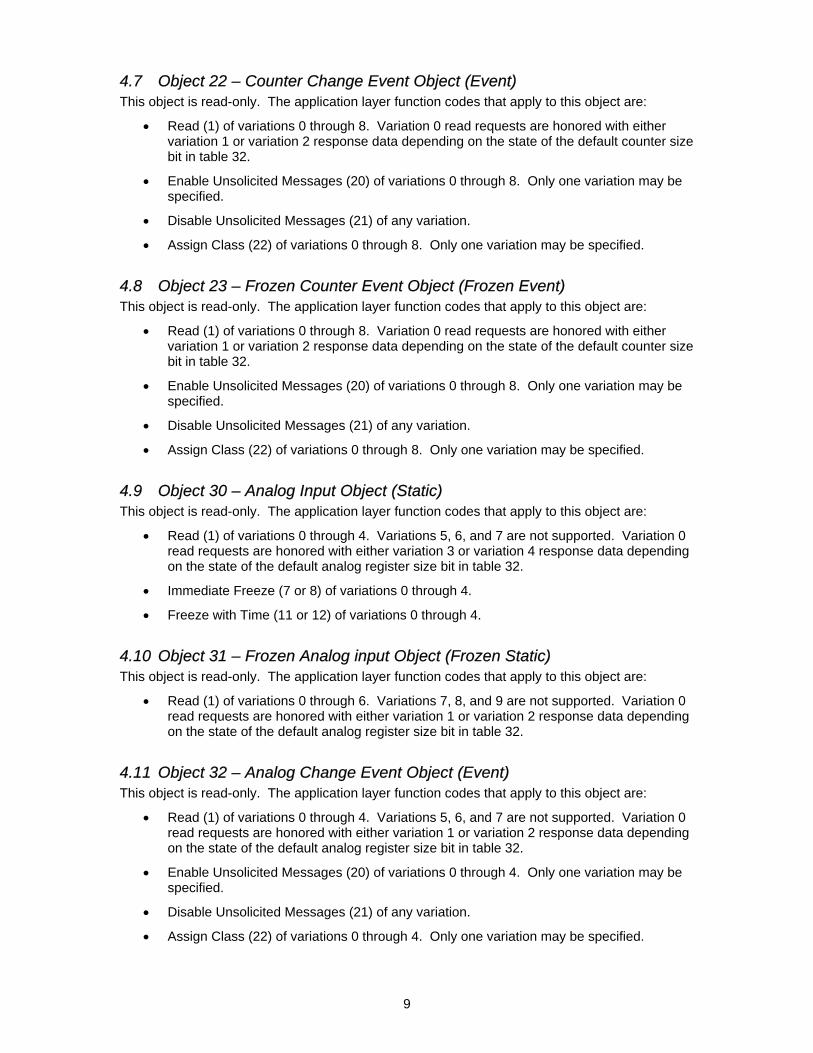
4.7 Object 22 – Counter Change Event Object (Event) This object is read-only. The application layer function codes that apply to this object are:
• Read (1) of variations 0 through 8. Variation 0 read requests are honored with either variation 1 or variation 2 response data depending on the state of the default counter size bit in table 32.
• Enable Unsolicited Messages (20) of variations 0 through 8. Only one variation may be specified.
• Disable Unsolicited Messages (21) of any variation.
• Assign Class (22) of variations 0 through 8. Only one variation may be specified.
4.8 Object 23 – Frozen Counter Event Object (Frozen Event) This object is read-only. The application layer function codes that apply to this object are:
• Read (1) of variations 0 through 8. Variation 0 read requests are honored with either variation 1 or variation 2 response data depending on the state of the default counter size bit in table 32.
• Enable Unsolicited Messages (20) of variations 0 through 8. Only one variation may be specified.
• Disable Unsolicited Messages (21) of any variation.
• Assign Class (22) of variations 0 through 8. Only one variation may be specified.
4.9 Object 30 – Analog Input Object (Static) This object is read-only. The application layer function codes that apply to this object are:
• Read (1) of variations 0 through 4. Variations 5, 6, and 7 are not supported. Variation 0 read requests are honored with either variation 3 or variation 4 response data depending on the state of the default analog register size bit in table 32.
• Immediate Freeze (7 or 8) of variations 0 through 4.
• Freeze with Time (11 or 12) of variations 0 through 4.
4.10 Object 31 – Frozen Analog input Object (Frozen Static) This object is read-only. The application layer function codes that apply to this object are:
• Read (1) of variations 0 through 6. Variations 7, 8, and 9 are not supported. Variation 0 read requests are honored with either variation 1 or variation 2 response data depending on the state of the default analog register size bit in table 32.
4.11 Object 32 – Analog Change Event Object (Event) This object is read-only. The application layer function codes that apply to this object are:
• Read (1) of variations 0 through 4. Variations 5, 6, and 7 are not supported. Variation 0 read requests are honored with either variation 1 or variation 2 response data depending on the state of the default analog register size bit in table 32.
• Enable Unsolicited Messages (20) of variations 0 through 4. Only one variation may be specified.
• Disable Unsolicited Messages (21) of any variation.
• Assign Class (22) of variations 0 through 4. Only one variation may be specified.

10
4.12 Object 33 – Frozen Analog Event Object (Frozen Event) This object is read-only. The application layer function codes that apply to this object are:
• Read (1) of variations 0 through 4. Variation 0 read requests are honored with either variation 1 or variation 2 response data depending on the state of the default analog register size bit in table 32.
• Enable Unsolicited Messages (20) of variations 0 through 4. Only one variation may be specified.
• Disable Unsolicited Messages (21) of any variation.
• Assign Class (22) of variations 0 through 4. Only one variation may be specified.
4.13 Object 34 – Analog Event Deadband Object No support is provided for this object.
4.14 Object 40 – Analog Output Status Object (Static) No support is provided for this object.
4.15 Object 41 – Analog Output Block Object (Static) No support is provided for this object.
4.16 Object 50 – Time and Date Object This object is used to set or get the meter time, and to apply timing information to freeze requests. The meter time has a resolution of 10 milliseconds, but an accuracy of only one or two seconds depending on the firmware version.
This object is read-write. The application layer function codes that apply to this object are:
• Read (1) of variations 0 or 1. Variation 2 is not supported for the read function. Variation 0 read requests are honored with variation 1 response data.
• Write (2) of variations 1 or 2.
4.17 Object 51 – Time and Date CTO Object This object is supported as part of the Object 2 Variation 3 data response.
4.18 Object 52 – Time Delay Object No support is provided for this object.
4.19 Object 60 – Class Data Object This object is read-only. The application layer function codes that apply to this object are:
• Read (1) of variations 1 through 4.
4.20 Object 70 – File Object No support is provided for this object.

11
4.21 Object 80 – Internal Indications Object This object is read-write. The application layer function codes that apply to this object are:
• Read (1) of variation 1.
• Write (2) of variation 1.
4.22 Objects 81 and Above No support is provided for these objects.

12
5 Power Up and System Initialization The DNP firmware configures itself according to the data stored in the meter’s control tables. The DNP configuration is valid until one of the critical control tables have been modified. If that happens, then the DNP firmware must re-initialize itself.
5.1 First Power Up The first time that a DNP protocol converter card is powered up, it sees that it has not been set up yet. The firmware then reads the control tables that apply to the protocol converter, and stores them in its non-volatile memory. Periodically, these same control tables will be re-read and checked for changes. If a change has occurred, then the first power up initialization sequence is re-executed.
At first power up no event or freeze commands are in force.
Counters that are associated with data block summation registers are initialized to whatever counts those summation registers currently contain.
5.2 Power Fail A power failure in the meter causes the protocol converter card to shut down. The DNP firmware stores event and freeze data on the protocol converter card, so all of that data is completely lost. The register data is maintained because it stored in the meter, not on the protocol converter card. Only the freeze and change event history is lost.
5.3 Idle Mode If the meter ever enters idle mode, then data polling will stop. When the meter re-enters record mode, then all of the data points are re-initialize with current data, and the event and freeze buffers are cleared.

13
6 LED’s The Protocol Converter Card has six LED’s labeled LED1 through LED6. These LED’s indicate the status of the host and meter communications, and the error status.
LED 1: On when data is being received from the DNP host.
LED 2: On when data is being transmitted to the DNP host.
LED 3: On when data is being received from the meter.
LED 4: On when data is being transmitted to the meter.
LED 5: On when DNP communications to the host are not possible, due to an error or due to the protocol converter card booting up. This LED turns off when the protocol converter card finishes its boot-up process, and is ready to communicate to the DNP host.
LED 6: Displays error codes by blinking on and off. The tens digit of the error code is a “long” on, while the units digit is a “short” on. A solid on, scintillating, condition indicates a “line break” has been detected and a recovery effort is underway. A very short on condition upon power up, reset by command or table reload is normal.
6.1 Error Codes The following error codes are defined:
11 Error communicating on meter port
12 Error communicating on DNP host port
13 Overrun error on DNP host port
14 Framing error on DNP host port
15 Parity error on DNP host port
21 Watchdog timer timeout
22 Configuration of RS-485 enables is wrong
23 Configuration of SCMX enables is wrong
24 RX not enabled correctly
25 Interface buffer to DNP host port is full
31 Meter is in Idle Mode
32 Invalid Table 0
33 Invalid Table 32
34 EEPROM failure
4X Internal stack overflow
5X Trace buffer alert
6.1.1 Error Code 11 – Meter Comm Error This error code is displayed when a communication error occurs between the protocol converter card and the meter. This error may occur from time to time but may recover immediately. In that event, there is no corrective action needed since this is a normal occurrence.
6.1.2 Error Code 12 – DNP Host Comm Error This error code is displayed when a communication error occurs between the protocol converter card and the DNP host. The current revision of DNP firmware (V016R00) does not set this error.
14
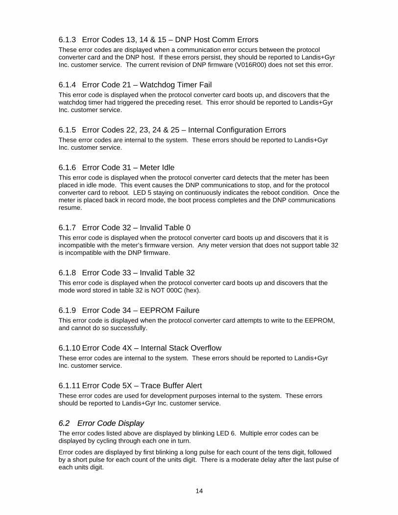
6.1.3 Error Codes 13, 14 & 15 – DNP Host Comm Errors These error codes are displayed when a communication error occurs between the protocol converter card and the DNP host. If these errors persist, they should be reported to Landis+Gyr Inc. customer service. The current revision of DNP firmware (V016R00) does not set this error.
6.1.4 Error Code 21 – Watchdog Timer Fail This error code is displayed when the protocol converter card boots up, and discovers that the watchdog timer had triggered the preceding reset. This error should be reported to Landis+Gyr Inc. customer service.
6.1.5 Error Codes 22, 23, 24 & 25 – Internal Configuration Errors These error codes are internal to the system. These errors should be reported to Landis+Gyr Inc. customer service.
6.1.6 Error Code 31 – Meter Idle This error code is displayed when the protocol converter card detects that the meter has been placed in idle mode. This event causes the DNP communications to stop, and for the protocol converter card to reboot. LED 5 staying on continuously indicates the reboot condition. Once the meter is placed back in record mode, the boot process completes and the DNP communications resume.
6.1.7 Error Code 32 – Invalid Table 0 This error code is displayed when the protocol converter card boots up and discovers that it is incompatible with the meter’s firmware version. Any meter version that does not support table 32 is incompatible with the DNP firmware.
6.1.8 Error Code 33 – Invalid Table 32 This error code is displayed when the protocol converter card boots up and discovers that the mode word stored in table 32 is NOT 000C (hex).
6.1.9 Error Code 34 – EEPROM Failure This error code is displayed when the protocol converter card attempts to write to the EEPROM, and cannot do so successfully.
6.1.10 Error Code 4X – Internal Stack Overflow These error codes are internal to the system. These errors should be reported to Landis+Gyr Inc. customer service.
6.1.11 Error Code 5X – Trace Buffer Alert These error codes are used for development purposes internal to the system. These errors should be reported to Landis+Gyr Inc. customer service.
6.2 Error Code Display The error codes listed above are displayed by blinking LED 6. Multiple error codes can be displayed by cycling through each one in turn.
Error codes are displayed by first blinking a long pulse for each count of the tens digit, followed by a short pulse for each count of the units digit. There is a moderate delay after the last pulse of each units digit.

15
For example, assume that there is a watchdog time failure and an EEPROM failure. LED 6 would blink two long pulses followed by one short pulse to indicate error code 21 (watchdog timer), then after a moderate pause, three long pulses followed by four short pulses to indicate error code 34 (EEPROM failure). If the error corrects itself, then that error code will be removed from the display cycle. If there are no errors to display, then LED 6 remains off.

7 Mapper Set-up
7.1 Display Configuration
7.1.1 Master Display Choices: Provides a list of Analogs & counters which can be selected as DNP information.
7.1.2 Port RS232 List: This list will allow a total of 32 Counters & Analogs to be selected as DNP information. This is the first list that will be looked at for numbering outputs. The first Analog will become 0 and will continue as they are in the list. The same will take place with counters. The next list that will be ordered, will come from table 31 and then table 30.
7.1.3 List Selection: This allows the user to select a location to store information to be sent back via DNP.
7.1.4 Scale Factors: The scale factor allows values to be scaled up or down to meet the customer and the DNP requirements. Example a value of 25.5 would be sent back as 25. The number could of been scaled up by 10, a value of 255 would then be returned.
Table 31 Display List
Table 30 Display List
Primary Display List for DNP

7.1.5 Ports Button: This allows for switching to Port Configuration.
7.2 Port Configuration 1(Display Lists, Binary Input List & Analog Data)
7.2.1 Displays Lists (Analog or counter values to be returned to the host.) Include Table 30 Display: Refers to the Current Loop List. Include Table 31 Display: Refers to the RS232-1 List.
7.2.2 Binary Input List (Errors, Input or Relay status reported back to host.) Include Error Status: When selected, the errors will be reported as status 0-3. See 2.11 for more detail. Include Status Inputs: When selected, the status will be reported on the auxiliary inputs, which are set to NO UNIT OF MEASURE. See 2.1.2 for more detail. Include Relay Status: When selected the status of each output relay will be report. See 2.1.3 for more detail.
7.2.3 Analog Data 16 Bits: A request to read, will cause data to be reported back to the host as 16 bit numbers.

32 Bits: A request to read, will cause data be reported back to the host as 32 bit numbers. Dead Band %: The amount of change required causing an analog change event to accrue.
7.3 Port Configuration 2 (Counter Data, Event Data Storage & Relay Outputs)
7.3.1 Counter Data 16 Bits: A request to read, will cause data to be reported back to the host as 16 bit numbers. 32 Bits: A request to read, will cause data to be reported back to the host as 32 bit numbers.
7.3.2 Event Data Enable Binary Event Storage: Allows Binary event storage on event change. Enable Analog Event Storage: Allows Analog event storage on Analog change. Enable Counter Event Storage: Allows Counter event storage on Counter change.
Enable Freeze Event Storage: Allows the meter to perform Freeze event storage when the parameters are sent to the meter from the Host.

Note: The Event Storage should only be enabled for the data that will be used. The data storage will allow a total of 5000 events to be stored. The 5000 buffers are allocated based on the number of event types and number of values for each event. Example: If you enabled all of the event storage types but only planed on using Freeze Event Storage, the number of Freeze events which can be stored will be reduced because part of the 5000 buffers will be allocated to the other event types and will NOT be available for Freeze storage.
7.3.3 Relay Outputs No Binary Outputs: Selecting No Binary Output will prevent any of the relays from being controlled with DNP commands. Select Before Operate: Select Before Operate requires the host to send two commands with the same data packet. The first command must be Select followed by the second command Operate with the same data packet that was sent with the Select command. Direct Operate with ACK: When this function is selected the meter will send the host an acknowledgement after the meter has received operate the relay command and the relay has operated. Direct Operate, no ACK: With this selection there will be no response from the meter after the meter receives the Operate command and the relay has operated.
7.4 Port Configuration 3 (Unsolicited Responses & Collision Avoidance)

7.4.1 Unsolicited Responses Enabled: Selecting Unsolicited Responses from the meter to the host. This will allow a master to set-up Unsolicited Responses within this meter. The response will only be sent to the unsolicited host address. Timeout Seconds: The time seconds will be supplied by the SCADA group if Unsolicited Response is enabled. Retries: The number of Retries will be supplied by the SCADA group if Unsolicited Response is enabled. Unsolicited Host Address: This is the address to which the unsolicited response will be sent. The Address will be supplied by the SCADA group if Unsolicited Response is enabled.
7.4.2 Collision Avoidance Enabled: Collision Avoidance should not be used for point to point communication. Max Random Delay: The delay time will be supplied by the SCADA group if Collision Avoidance is enabled.
7.5 Port Configuration 4 (Data Link Layer & Baud Rate)
7.5.1 Data Link Layer Enable Confirmations: This will be enabled if used by the SCADA Department. See section 1.3.1 Enable Retries (Fixed at 2): If retries will be used is a function if used by the SCADA Department. See section 1.3.2
7.5.2 Baud Rate The baud rate will be selected based on the communication system. This information would normally be supplied by the SCADA Department.
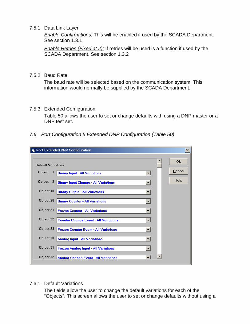
7.5.3 Extended Configuration Table 50 allows the user to set or change defaults with using a DNP master or a DNP test set.
7.6 Port Configuration 5 Extended DNP Configuration (Table 50)
7.6.1 Default Variations The fields allow the user to change the default variations for each of the “Objects”. This screen allows the user to set or change defaults without using a

DNP master or a DNP test set.Note: Table 50 is only available in firmware versions 2751, 2752 and 57xx.
7.7 Port Configuration 6 Extended DNP Configuration (Table 50)
7.7.1 Pre Transmit Delay The field will allow the user to set the Pre Transmit Delay after asserting RTS, before the first byte of a message is transmitted. The minimum value is zero (no delay) and the maximum value is 255 (2550 milliseconds, or 2.55 seconds). This field is ignored if collision avoidance is enabled, since collision avoidance has its own delay rules. CTS is ignored if the field is non-zero. The transmit will began as soon as the specified delay is complete, rather than waiting for CTS to be asserted.
7.7.2 Post Transmit Delay The field will allow the user to set the Post Transmit Delay, forces a delay before de-asserting RTS, after the last byte of a message is transmitted. The minimum value is zero (no delay) and the maximum value is 255 (2550 milliseconds, or 2.55 seconds). This field is ignored if the pre-transmit delay is zero.

7.7.3 Time Sync Request & Time Sync Period These fields specify a time sync is requested and the frequency, which the time sync is requested. The “Protocol Converter Card” (RTU) will never request a time sync, or it can request time sync every “X” minutes, “X” hours, “X” days, “X” weeks and “X” months.
7.7.4 Time Sync Request & Time Sync Period These fields specify a time sync is requested and the frequency, which the time sync is requested. The “Protocol Converter Card” (RTU) will never request a time sync, or it can request time sync every “X” minutes, “X” hours, “X” days, “X” weeks and “X” months.
7.7.5 Freeze Minutes This field sets the freeze interval in the meter (Protocol Card). If this field is set to zero, then no freeze is generated. Otherwise, the valid values for this field are any number of minutes that is an even factor of 60: 1, 2, 3, 4, 5, 6, 10,12, 15,20, 30 or 60. Additionally, any even factor of 24 hours may be used: 60,120,180, 360, 480, 720 or 1440. In all cases, the freeze will occur on the even interval minute or hour. An example, if 20 minutes is specified, the freeze will occur on the hour, on the 20-minute mark and on the 40-minute mark. If 720-minutes was specified, than the freeze will occur at midnight and noon.

7.8 Port Configuration 7 Extended DNP Configuration (Table 50)
7.8.1 Data Point Configurations This set of fields allow the customer to configure a particular set of data points in a specific way.
8 Maxcom Set-up Program Mode
8.1 Download list - Port Configuration The list of items on the screen below can be changed or set at the time of programming.

8.1.1 Baud Rate See section 7.5.2
8.1.2 Device Address This is the SCADA address of the meter. This address is normally provide by the SCADA Department.
8.1.3 Host Address See section 7.4.1
8.1.4 Collision Detection / Avoidance & Delays See section 7.4.2
8.1.5 Unsolicited Responses, Timeouts & Retries See section 7.4.1
8.1.6 Data Link Layer, Confirmations & Retries See section 7.5.1

8.1.7 Counter & Analog Data Size See section 7.3.1
8.1.8 Analog Dead Band %: See section 7.2.3
8.1.9 Include Display Lists This allows lists for tables 30 & 31 to be used as one output list for DNP Analog and Counter (Allowing a total of 96 variables to be selected) Values. See section 7.1.2 for more information.

9 Maxcom Edit Program Mode
9.1 Edit Mode List - Port Configuration The list of items on the screen below can be edited after the meter has been programming.
9.1.1 Edit Variables: See section 8 for details of each variable.

10 Maxcom Data Collection Mode
10.1 Table RS232 Data Collection Mode The information on the screen below can be used to verify the DNP setting in the meter.
10.1.1 Mode: This is the protocol the meter firmware expects on the protocol converter board. Note: DNP 3.0 Level 2 will be mode “12”. The mode field is used by the MAXsys or Quad4+ firmware to determine the function of the RS232-2 serial port. The DNP level 2 firmware uses mode value 0x000C. The other mode values are listed below for reference. Any value not listed is undefined and causes the port to be disabled. 0x0003 PGE protocol 0x0004 DNP (older version; not level 2) 0x0005 CEBUS protocol 0x0006 External RS232 (Type 7 protocol)

0x0007 External RS232 (Type 7 protocol with master/slave) 0x0008 SES-92 protocol 0x0009 MMS protocol 0x000A External RS232 (Type 7 protocol with master/slave, RTS) 0x000B MODBUS protocol 0x000C DNP 3 Level 2 protocol
10.1.2 Flag: This is the list of 16 bits which will be set based on the option which have been selected, see the following list for selected options. The following flags are defined: Bit 0 1 = Enable Freeze Event data colection Bits 1 & 2 00 = No Binary outputs
01 = Binary outputs are Select Before Operate 10 = Binary outputs are Direct Operate with Acknowledge 11 = Binary outputs are Direct Operate, No ACK
Bit 3 1 = Enable “Binary Input Change Event” data collection Bit 4 1 = Enable “Analog Input Change Event” data collection Bit 5 1 = Enable “Counter Change Event” data collection Bit 6 1 = Enable Collision detection/avoidance Bit 7 1 = Enable Unsolicited responses Bit 8 1 = Include Profile data in counter list Bit 9 1 = Include Error Status in binary input list Bit 10 1 = Include Status Inputs in binary input list Bit 11 1 = Include Relay Output Status in binary input list Bit 12 1 = Enable Data-Link confirmations when sending Bit 13 1 = Enable Data-Link retries (fixed at 2) Bit 14 Default Counter size: 1 = 16 bit, 0 = 32 bit Bit 15 Default Analog size: 1 = 16 bit, 0 = 32 bit
10.1.3 Value: This field, “value” Field (Collision Avoidance Max Random Delay) The value field is a 16-bit word, only the bottom byte of which is used. The upper byte should be set to zero for future compatibility purposes.

The bottom byte holds the maximum random delay used in the collision avoidance function. The units are 10’s of milliseconds. The minimum value is zero (no random delay), and the maximum value is 255 (2550 milliseconds, or 2.55 seconds). The least significant byte of the “gen” field is used as the fixed collision avoidance delay value, as well as its primary purpose which is the low byte of the device address.
10.1.4 Baud: This field tells you at what communications speed the protocol board expects the host to communicate at. The baud field holds a 16-bit code for the baud rate at which the DNP host channel should operate. The values defined below apply to all protocols, not just DNP: 0 = 300 baud 1 = 600 baud 2 = 1200 baud 3 = 2400 baud 4 = 4800 baud 5 = 9600 baud 6 = 19200 baud
10.1.5 Gen: This field, gen” Field (DNP Device Address and DNP Host Address) The gen field is a 4-element array of bytes. This field is reserved for a “unit-id” in whatever protocol is selected. The DNP firmware splits this field into two 16-bit words. The bottom word (bytes 0 and 1) of this field contains the meter’s DNP address. The DNP address is a 16-bit binary value in the range of 0 to 0xffef. Addresses 0xfff0 through 0xffff are reserved for host generated broadcast messages and are not allowed to be used as unit addresses. Byte 0 plays a dual role. Besides being the bottom byte of the meter’s DNP device address, this byte is also used as the “fixed” collision avoidance delay time. The delay time is the byte 0 value multiplied by 10 milliseconds. The upper word (bytes 2 and 3) of this field is used for the master destination address when sending unsolicited messages. This address is also in the range of 0 to 0xffef.
10.1.6 Table : This field, “table_no” Field (Unsolicited Response Timeout and Retries)

The table_no field is a single byte. This field was intended to define the table number where the display items could be found. However, since that table is always table 16, this field can be used for something else. In this case it is used define unsolicited response confirmation retries and timeouts. The bottom 4 bits (bits 0-3) of this byte define the unsolicited response timeout according to the following table:
Value Timeout 0 Infinity 1-10 1 to 10 seconds 11 15 seconds 12 20 seconds 13 30 seconds 14 45 seconds 15 60 seconds The upper 4 bits (bits 4-7) of this byte define the unsolicited response retry count according to the following table:
Value Number of Retries 0 None 1-14 1 to 14 retries 15 Infinite retries
10.1.7 Output Type: output_type” Field (Analog Reporting Deadband) The output_type field is a single byte. This field also has limited usefulness as it was originally intended, so its definition has changed for DNP. This field is used to define the “deadband” for reporting analog input change events. The deadband defines how far the input may stray from its last reported value before a new event should be generated. The units of this field are in tenths of a percent. The minimum value is zero (0.0 percent), and the maximum value is 255 (25.5 percent). This field affects all analog input values. However, the deadband reporting may be modified by the use of object 34 for specific analog data points.

11 Hardware
11.1 Protocol Converter Board
Protocol Converter Board:
E1
E2
E3
E4
E5
E6E7
E8E9 E10
11.1.1 Jumper Installations Protocol Board
Host Serial Ports (connection from Protocol Board to host computer):
Port Jumper Position Function
E1 Not Used On Standard Board
**** E1 A Common Ground
**** E1 B Isolated Ground
RS-232 (J2) E2 A RX data
RS-485 (J2) E2 B RX data
E1
Diagnostic LEDs
DNP Program EPROM
V25 Processor
E2
E3
E4
E5
E7
E6
E10 E9 E8

**** E2 B Isolated RS232
E3 *Not Used Ring indicate
E4 A RS232 CTS used, signal from external source
E4 B RS232 CTS not used & RS485
E5 Don’t Care RS232
RS485 E5 A RX data Recommended
**** E5 B RX data Isolated RS232
E6 In RS485 Terminated Not Recommended
E6 Out RS485 Un-terminated Recommended
E7 N/A Not customer configurable
E8 N/A Not customer configurable
Meter Serial Port (connection from Protocol Board to CPU of meter):
Jumper Position Function
E9 In TXD connected to backplane (standard)RS232-2
E9 Out RXD connected to RS-232 external RS232-1
E10 A RXD connected to backplane (standard)RS232-2
E10 B RXD connected to RS-232 external RS232-1
Example of jumper settings:
Application:
Configured to talk to the meter processor on the SuperBoard over the backplane (i.e., bus) on the Mother Board. The host interface is RS-232 with CTS not used.
Jumpers on Protocol Converter Board:
For meter serial port: E9 In; E10 on A.
For host connection: E2 on A, , E4 on B, E5 on A.
NOTE: You can convert from RS232 to RS485 by moving E2 from the jumper from “A” to “B”.
**** Indicates position NOT USED on standard board.
Jumpers on SuperBoard:
E9 in position 2-3 for operation with Protocol Converter
Note: If E9 is in position 1-2, RS-232 port #2 is active for other purposes.

11.2 Display Board SuperBoard, Component and Solder Side:
11.2.1 Jumper Installations Display Board E9 in position 2-3 for operation with Protocol Converter

12 Device Profile Document
DNP V3.00
DEVICE PROFILE DOCUMENT
Vendor Name: Landis + Gyr Inc.
Device Name: MAXsys 2510 Solid State Meter with optional Protocol Converter Board;
Protocol Converter Board firmware version V016, revision R07.
Highest DNP Level Supported:
For Requests : 2
For Responses : 2
Device Function:
Master ⌧ Slave
Notable objects, functions, and / or qualifiers supported in addition to the Highest DNP Levels
Supported (the complete list is described in the attached table):
See attached
Maximum Data Link Frame Size (octets):
Transmitted 292
Received (must be 292)
Maximum Application Fragment Size (octets):
Transmitted 2048 (if >2048, must
be configurable
Received 1024 (must be >= 249)
Maximum Data Link Re-tries:
None Fixed at _______________________ ⌧ Configurable, range: 0 or 2
Maximum Application Layer Re-tries:
⌧ None
Configurable, range _______ to _______
(Fixed is not permitted)

Requires Data Link Layer Confirmation:
Never Always Sometimes If 'Sometimes', when? ______________________________________________ ⌧ Configurable If 'Configurable', how? Table32 Flag1.Bit12
Requires Application Layer Confirmation:
Never Always (not recommended) ⌧ When reporting Event Data (Slave devices only) ⌧ When sending multi-fragment responses (Slave devices only)
Sometimes If 'Sometimes', when? ______________________________________________ Configurable If 'Configurable', how? ______________________________________________
Timeouts while waiting for:
Data Link Confirm None ⌧ Fixed at 1 second Variable Configurable Complete Appl. Fragment ⌧ None Fixed at _________ Variable Configurable Application Confirm None ⌧ Fixed at 3 seconds Variable Configurable Complete Appl. Response ⌧ None Fixed at _________ Variable Configurable Others The baud field in table 32 holds a 2-bit code in bits 5 and 4 of the 16-bit field for DNP transmit timeout. If the value is programmed, the DNP firmware will cause a reset after the defined period if it has not responded to DNP activity. The timeout needs a first DNP activity. 0 = No timeout resets, 1 = Two minute timeout resets, 2 = One hour timeout resets and 3 = One day timeout reset.__________________________________________________________________________ Attach explanation if 'Variable' or 'Configurable' was checked for any timeout
Sends/Executes Control Operations:
WRITE Binary Outputs ⌧ Never Always Sometimes Configurable SELECT/OPERATE Never Always Sometimes ⌧ Configurable† DIRECT OPERATE Never Always Sometimes ⌧ Configurable† DIRECT OPERATE - NO ACK Never Always Sometimes ⌧ Configurable†
Count > 1 ⌧ Never Always Sometimes Configurable Pulse On Never ⌧ Always Sometimes Configurable Pulse Off ⌧ Never Always Sometimes Configurable Latch On Never ⌧ Always Sometimes Configurable Latch Off Never ⌧ Always Sometimes Configurable Trip/Close ⌧ Never Always Sometimes Configurable Raise/Lower ⌧ Never Always Sometimes Configurable
Queue ⌧ Never Always Sometimes Configurable Clear Queue Never ⌧ Always Sometimes Configurable
† To support control operations and conform to the Subset Definitions, either 'Always' or 'Configurable' must be selected.

WRITE Analog Outputs ⌧ Never Always Sometimes Configurable SELECT/OPERATE ⌧ Never Always Sometimes Configurable† DIRECT OPERATE ⌧ Never Always Sometimes Configurable† DIRECT OPERATE - NO ACK ⌧ Never Always Sometimes Configurable†
Maximum Select/Execute Delay Time: Not Applicable ⌧ Fixed at 4 seconds Configurable, range _______ to _______ seconds
Attach explanation if 'Sometimes' or 'Configurable' was checked for any operation.
FILL OUT THE FOLLOWING ITEM FOR MASTER DEVICES ONLY: Expects Binary Input Change Events:
Either time-tagged or non-time-tagged for a single event Both time-tagged and non-time-tagged for a single event Configurable (attach explanation)
FILL OUT THE FOLLOWING ITEMS FOR SLAVE DEVICES ONLY:

TimeSync Information : a.) TimeSync Period
Never Fixed at _______ seconds ⌧Configurable, range _1 minute_ to _255 Months (4 weeks per month)
b.) Maximum time base drift over a 10 minute interval : < 1 ms c.) Maximum Internal Time Reference Error when set via DNP : 2000 ms d.) Maximum Delay Measurement error : 20 ms e.) Maximum response time : 1000 ms f.) Event data time-tag error - if different than (c) : Binary Input Change Events _________ ms Counter Change Events _________ ms Frozen Counter Change Events _________ ms Analog Change Events _________ ms Frozen Analog Change Events _________ ms
Reports Binary Input Change Events when no specific variation requested:
Never Only time-tagged Only non-time-tagged ⌧ Configurable to send both, one or the other (attach explanation) Table 50 default
variation configuration
Reports time-tagged Binary Input Change Events when no specific variation requested:
Never Binary Input Change With Time Binary Input Change With Relative Time ⌧ Configurable (attach explanation) Table 50 default variation configuration
Sends Unsolicited Responses: ⌧ Never
Configurable (attach explanation) Only certain objects Sometimes (attach explanation)
⌧ ENABLE/DISABLE UNSOLICITED Function codes supported
Sends Static Data in Unsolicited Responses: ⌧ Never
When Device Restarts When Status Flags Change
No other options are permitted.
Supports Collision Avoidance:
Never Always ⌧ Configurable (attach explanation)
Collision Avoidance Detection Method:
Not Applicable ⌧ Link Activity
DCD - with aid of external device DCD - without aid of external device

Default Counter Object/Variation:
No Counters Reported ⌧ Configurable (attach explanation)
Default Object ______________ Default Variation ______________
Point-by-point list attached
Counters Roll Over at:
No Counters Reported Configurable (attach explanation) 16 Bits 32 Bits ⌧ Other Value _Depends on counter size_
Point-by-point list attached
Source Address Filtering: ⌧ Not Supported
Configurable (attach explanation)
Sends Multi-Fragment Responses: ⌧ Yes No

40
13 DNP 3.00 Implementation Table
DNP 3.00 - IMPLEMENTATION TABLE
OBJECT
REQUEST
(slave must parse)
RESPONSE
(master must parse)
Obj
Var
Description
Func Codes (dec)
Qual Codes (hex)
Func Codes
Qual Codes (hex)
1
0
Binary Input – All Variations
1(Read) 00,01(Start-Stop) 06(All Data)
1
1*
Binary Input
1(Read) 00,01(Start-Stop) 06(All Data)
129 (Resp) 00 (Start-Stop)
1
2
Binary Input with Status
1(Read) 00,01(Start-Stop)
06(All Data)
129 (Resp) 00 (Start-Stop)
2
0
Binary Input Change – All Variations
1(Read) 20(En Unsol) 21(Dis Unsol) 22(Assign Cl)
06(All Data) 07,08(Limited Qty)
2
1*
Binary Input Change without Time
1(Read) 20(En Unsol) 21(Dis Unsol) 22(Assign Cl)
06(All Data) 07,08(Limited Qty)
129 (Resp)
28 (Index)
2
2
Binary Input Change with Time
1(Read) 20(En Unsol) 21(Dis Unsol) 22(Assign Cl)
06(All Data) 07,08(Limited Qty)
129 (Resp)
28 (Index)
2
3
Binary Input Change with Relative Time
1(Read) 20(En Unsol)
21(Dis Unsol)
22(Assign Cl)
06(All Data)
07,08(Limited Qty)
129 (Resp)
28 (Index)
10
0
Binary Output – All Variations
1(Read) 00,01(Start-Stop) 06(All Data)
10
1
Binary Output
None
10
2*
Binary Output Status
1(Read) 00,01(Start-Stop)
06(All Data)
129 (Resp) 00 (Start-Stop)
12
0
Control Block – All Variations
None
12
1
Control Relay Output Block
3(Select) 4(Operate) 5(Dir Operate) 6(Dop/NoAck
17,28 (Index) 129 (Resp) Echo of Request
12
2
Pattern Control Block
None
12
3
Pattern Mask None

41
OBJECT
REQUEST
(slave must parse)
RESPONSE
(master must parse)
Obj
Var
Description
Func Codes (dec)
Qual Codes (hex)
Func Codes
Qual Codes (hex)
20
0
Binary Counter - All Variations
1(Read) 7(Imm Freeze) 8(Imm Freeze, NoAck) 9(Frz & Clr) 10(Frz & Clr, NoAck) 11(Frz/Time) 12(Frz/Time, NoAck)
00,01(Start-Stop) 06(All Data)
20
1
32-Bit Binary Counter
1(Read) 7(Imm Freeze) 8(Imm Freeze, NoAck) 9(Frz & Clr) 10(Frz & Clr, NoAck) 11(Frz/Time) 12(Frz/Time, NoAck)
00,01(Start-Stop) 06(All Data)
129 (Resp) 00 (Start-Stop)
20
2
16-Bit Binary Counter
1(Read) 7(Imm Freeze) 8(Imm Freeze, NoAck) 9(Frz & Clr) 10(Frz & Clr, NoAck) 11(Frz/Time) 12(Frz/Time, NoAck)
00,01(Start-Stop) 06(All Data)
129 (Resp) 00 (Start-Stop)
20
3
32-Bit Delta Counter
1(Read) 7(Imm Freeze) 8(Imm Freeze, NoAck) 9(Frz & Clr) 10(Frz & Clr, NoAck) 11(Frz/Time) 12(Frz/Time, NoAck)
00,01(Start-Stop) 06(All Data)
129 (Resp) 00 (Start-Stop)
20
4
16-Bit Delta Counter
1(Read) 7(Imm Freeze) 8(Imm Freeze, NoAck) 9(Frz & Clr) 10(Frz & Clr, NoAck) 11(Frz/Time) 12(Frz/Time, NoAck)
00,01(Start-Stop) 06(All Data)
129 (Resp) 00 (Start-Stop)

42
OBJECT
REQUEST
(slave must parse)
RESPONSE
(master must parse)
Obj
Var
Description
Func Codes (dec)
Qual Codes (hex)
Func Codes
Qual Codes (hex)
20
5*
32-Bit Binary Counter without Flag
1(Read) 7(Imm Freeze) 8(Imm Freeze, NoAck) 9(Frz & Clr) 10(Frz & Clr, NoAck) 11(Frz/Time) 12(Frz/Time, NoAck)
00,01(Start-Stop) 06(All Data)
129 (Resp) 00 (Start-Stop)
20
6
16-Bit Binary Counter without Flag
1(Read) 7(Imm Freeze) 8(Imm Freeze, NoAck) 9(Frz & Clr) 10(Frz & Clr, NoAck) 11(Frz/Time) 12(Frz/Time, NoAck)
00,01(Start-Stop) 06(All Data)
129 (Resp) 00 (Start-Stop)
20
7
32-Bit Delta Counter without Flag
1(Read) 7(Imm Freeze) 8(Imm Freeze, NoAck) 9(Frz & Clr) 10(Frz & Clr, NoAck) 11(Frz/Time) 12(Frz/Time, NoAck)
00,01(Start-Stop) 06(All Data)
129 (Resp) 00 (Start-Stop)
20
8
16-Bit Delta Counter without Flag
1(Read)
7(Imm Freeze)
8(Imm Freeze, NoAck)
9(Frz & Clr)
10(Frz & Clr, NoAck)
11(Frz/Time)
12(Frz/Time, NoAck)
00,01(Start-Stop)
06(All Data)
129 (Resp) 00 (Start-Stop)

43
OBJECT
REQUEST
(slave must parse)
RESPONSE
(master must parse)
Obj
Var
Description
Func Codes (dec)
Qual Codes (hex)
Func Codes
Qual Codes (hex)
21
0
Frozen Counter - All Variations
1(Read) 00,01(Start-Stop)
06(All Data)
21
1*
32-Bit Frozen Counter
1(Read) 00,01(Start-Stop)
06(All Data)
129 (Resp)
00 (Start-Stop)
21
2
16-Bit Frozen Counter
1(Read) 00,01(Start-Stop)
06(All Data)
129 (Resp) 00 (Start-Stop)
21
3
32-Bit Frozen Delta Counter
1(Read) 00,01(Start-Stop)
06(All Data)
129 (Resp)
00 (Start-Stop)
21
4
16-Bit Frozen Delta Counter
1(Read)
00,01(Start-Stop)
06(All Data)
129 (Resp) 00 (Start-Stop)
21
5
32-Bit Frozen Counter with Time of Freeze
1(Read)
00,01(Start-Stop)
06(All Data)
129 (Resp) 00 (Start-Stop)
21
6
16-Bit Frozen Counter with Time of Freeze
1(Read) 00,01(Start-Stop)
06(All Data)
129 (Resp) 00 (Start-Stop)
21
7
32-Bit Frozen Delta Counter with Time of Freeze
1(Read)
00,01(Start-Stop)
06(All Data)
129 (Resp)
00 (Start-Stop)
21
8
16-Bit Frozen Delta Counter with Time of Freeze
1(Read)
00,01(Start-Stop)
06(All Data)
129 (Resp)
00 (Start-Stop)
21
9
32-Bit Frozen Counter without Flag
1(Read)
00,01(Start-Stop)
06(All Data)
129 (Resp) 00 (Start-Stop)
21
10
16-Bit Frozen Counter without Flag
1(Read) 00,01(Start-Stop)
06(All Data)
129 (Resp) 00 (Start-Stop)
21
11
32-Bit Frozen Delta Counter without Flag 1(Read)
00,01(Start-Stop)
06(All Data)
129 (Resp)
00 (Start-Stop)
21
12
16-Bit Frozen Delta Counter without Flag 1(Read)
00,01(Start-Stop)
06(All Data)
129 (Resp) 00 (Start-Stop)
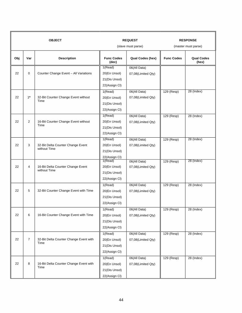
44
OBJECT
REQUEST
(slave must parse)
RESPONSE
(master must parse)
Obj
Var
Description
Func Codes (dec)
Qual Codes (hex)
Func Codes
Qual Codes (hex)
22
0
Counter Change Event – All Variations
1(Read)
20(En Unsol)
21(Dis Unsol)
22(Assign Cl)
06(All Data)
07,08(Limited Qty)
22
1*
32-Bit Counter Change Event without Time
1(Read)
20(En Unsol)
21(Dis Unsol)
22(Assign Cl)
06(All Data)
07,08(Limited Qty)
129 (Resp)
28 (Index)
22
2
16-Bit Counter Change Event without Time
1(Read)
20(En Unsol)
21(Dis Unsol)
22(Assign Cl)
06(All Data)
07,08(Limited Qty)
129 (Resp)
28 (Index)
22
3
32-Bit Delta Counter Change Event without Time
1(Read)
20(En Unsol)
21(Dis Unsol)
22(Assign Cl)
06(All Data)
07,08(Limited Qty)
129 (Resp)
28 (Index)
22
4
16-Bit Delta Counter Change Event without Time
1(Read)
20(En Unsol)
21(Dis Unsol)
22(Assign Cl)
06(All Data)
07,08(Limited Qty)
129 (Resp)
28 (Index)
22
5
32-Bit Counter Change Event with Time
1(Read)
20(En Unsol)
21(Dis Unsol)
22(Assign Cl)
06(All Data)
07,08(Limited Qty)
129 (Resp)
28 (Index)
22
6
16-Bit Counter Change Event with Time
1(Read)
20(En Unsol)
21(Dis Unsol)
22(Assign Cl)
06(All Data)
07,08(Limited Qty)
129 (Resp)
28 (Index)
22
7
32-Bit Delta Counter Change Event with Time
1(Read)
20(En Unsol)
21(Dis Unsol)
22(Assign Cl)
06(All Data)
07,08(Limited Qty)
129 (Resp)
28 (Index)
22
8
16-Bit Delta Counter Change Event with Time
1(Read)
20(En Unsol)
21(Dis Unsol)
22(Assign Cl)
06(All Data)
07,08(Limited Qty)
129 (Resp)
28 (Index)
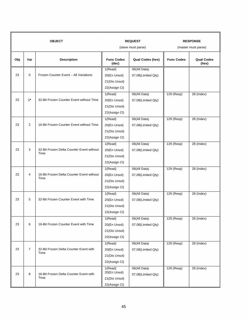
45
OBJECT
REQUEST
(slave must parse)
RESPONSE
(master must parse)
Obj
Var
Description
Func Codes (dec)
Qual Codes (hex)
Func Codes
Qual Codes (hex)
23
0
Frozen Counter Event – All Variations
1(Read)
20(En Unsol)
21(Dis Unsol)
22(Assign Cl)
06(All Data)
07,08(Limited Qty)
23
1*
32-Bit Frozen Counter Event without Time
1(Read)
20(En Unsol)
21(Dis Unsol)
22(Assign Cl)
06(All Data)
07,08(Limited Qty)
129 (Resp)
28 (Index)
23
2
16-Bit Frozen Counter Event without Time
1(Read)
20(En Unsol)
21(Dis Unsol)
22(Assign Cl)
06(All Data)
07,08(Limited Qty)
129 (Resp)
28 (Index)
23
3
32-Bit Frozen Delta Counter Event without Time
1(Read)
20(En Unsol)
21(Dis Unsol)
22(Assign Cl)
06(All Data)
07,08(Limited Qty)
129 (Resp)
28 (Index)
23
4
16-Bit Frozen Delta Counter Event without Time
1(Read)
20(En Unsol)
21(Dis Unsol)
22(Assign Cl)
06(All Data)
07,08(Limited Qty)
129 (Resp)
28 (Index)
23
5
32-Bit Frozen Counter Event with Time
1(Read)
20(En Unsol)
21(Dis Unsol)
22(Assign Cl)
06(All Data)
07,08(Limited Qty)
129 (Resp)
28 (Index)
23
6
16-Bit Frozen Counter Event with Time
1(Read)
20(En Unsol)
21(Dis Unsol)
22(Assign Cl)
06(All Data)
07,08(Limited Qty)
129 (Resp)
28 (Index)
23
7
32-Bit Frozen Delta Counter Event with Time
1(Read)
20(En Unsol)
21(Dis Unsol)
22(Assign Cl)
06(All Data)
07,08(Limited Qty)
129 (Resp)
28 (Index)
23
8
16-Bit Frozen Delta Counter Event with Time
1(Read) 20(En Unsol)
21(Dis Unsol)
22(Assign Cl)
06(All Data)
07,08(Limited Qty)
129 (Resp)
28 (Index)

46
OBJECT
REQUEST
(slave must parse)
RESPONSE
(master must parse) Obj
Var
Description
Func Codes
(dec)
Qual Codes (hex)
Func Codes
Qual Codes
(hex) 30
0
Analog Input – All Variations
1(Read) 7(Imm Freeze) 8(Imm Freeze, NoAck) 11(Frz/Time) 12(Frz/Time, NoAck)
00,01(Start-Stop) 06(All Data)
30
1
32-Bit Analog Input
1(Read) 7(Imm Freeze) 8(Imm Freeze, NoAck) 11(Frz/Time) 12(Frz/Time, NoAck)
00,01(Start-Stop) 06(All Data)
129 (Resp) 00 (Start-Stop)
30
2
16-Bit Analog Input
1(Read) 7(Imm Freeze) 8(Imm Freeze, NoAck) 11(Frz/Time) 12(Frz/Time, NoAck)
00,01(Start-Stop) 06(All Data)
129 (Resp) 00 (Start-Stop)
30
3*
32-Bit Analog Input without Flag
1(Read) 7(Imm Freeze) 8(Imm Freeze, NoAck) 11(Frz/Time) 12(Frz/Time, NoAck)
00,01(Start-Stop) 06(All Data)
129 (Resp) 00 (Start-Stop)
30
4
16-Bit Analog Input without Flag
1(Read)
7(Imm Freeze)
8(Imm Freeze, NoAck)
11(Frz/Time)
12(Frz/Time, NoAck)
00,01(Start-Stop) 06(All Data)
129 (Resp) 00 (Start-Stop)
31
0
Frozen Analog Input – All Variations
1(Read)
00,01(Start-Stop) 06(All Data)
31
1
32-Bit Frozen Analog Input
1(Read) 00,01(Start-Stop) 06(All Data)
129 (Resp) 00 (Start-Stop)
31
2
16-Bit Frozen Analog Input
1(Read) 00,01(Start-Stop)
06(All Data)
129 (Resp) 00 (Start-Stop)
31
3
32-Bit Frozen Analog Input with Time of Freeze
1(Read) 00,01(Start-Stop)
06(All Data)
129 (Resp) 00 (Start-Stop)
31
4
16-Bit Frozen Analog Input with Time of Freeze
1(Read) 00,01(Start-Stop)
06(All Data)
129 (Resp) 00 (Start-Stop)
31
5*
32-Bit Frozen Analog Input without Flag 1(Read) 00,01(Start-Stop)
06(All Data)
129 (Resp) 00 (Start-Stop)
31
6
16-Bit Frozen Analog Input without Flag 1(Read) 00,01(Start-Stop)
06(All Data)
129 (Resp) 00 (Start-Stop)

47
OBJECT
REQUEST
(slave must parse)
RESPONSE
(master must parse) Obj
Var
Description
Func Codes
(dec)
Qual Codes (hex)
Func Codes
Qual Codes
(hex) 32
0
Analog Change Event - All Variations
1(Read) 20(En Unsol)
21(Dis Unsol)
22(Assign Cl)
06(All Data)
07,08(Limited Qty)
32
1*
32-Bit Analog Change Event without Time
1(Read) 20(En Unsol)
21(Dis Unsol)
22(Assign Cl)
06(All Data)
07,08(Limited Qty)
129 (Resp)
28 (Index)
32
2
16-Bit Analog Change Event without Time
1(Read) 20(En Unsol)
21(Dis Unsol)
22(Assign Cl)
06(All Data)
07,08(Limited Qty)
129 (Resp)
28 (Index)
32
3
32-Bit Analog Change Event with Time
1(Read)
20(En Unsol)
21(Dis Unsol)
22(Assign Cl)
06(All Data)
07,08(Limited Qty)
129 (Resp)
28 (Index)
32
4
16-Bit Analog Change Event with Time
1(Read)
20(En Unsol)
21(Dis Unsol)
22(Assign Cl)
06(All Data)
07,08(Limited Qty)
129 (Resp)
28 (Index)
33
0
Frozen Analog Event - All Variations
1(Read)
20(En Unsol)
21(Dis Unsol)
22(Assign Cl)
06(All Data)
07,08(Limited Qty)
33
1*
32-Bit Frozen Analog Event without Time
1(Read)
20(En Unsol)
21(Dis Unsol)
22(Assign Cl)
06(All Data)
07,08(Limited Qty)
129 (Resp)
28 (Index)
33
2
16-Bit Frozen Analog Event without Time
1(Read)
20(En Unsol)
21(Dis Unsol)
22(Assign Cl)
06(All Data)
07,08(Limited Qty)
129 (Resp)
28 (Index)
33
3
32-Bit Frozen Analog Event with Time
1(Read)
20(En Unsol)
21(Dis Unsol)
22(Assign Cl)
06(All Data)
07,08(Limited Qty)
129 (Resp)
28 (Index)
33
4
16-Bit Frozen Analog Event with Time
1(Read) 20(En Unsol) 21(Dis Unsol) 22(Assign Cl)
06(All Data)
07,08(Limited Qty)
129 (Resp)
28 (Index)
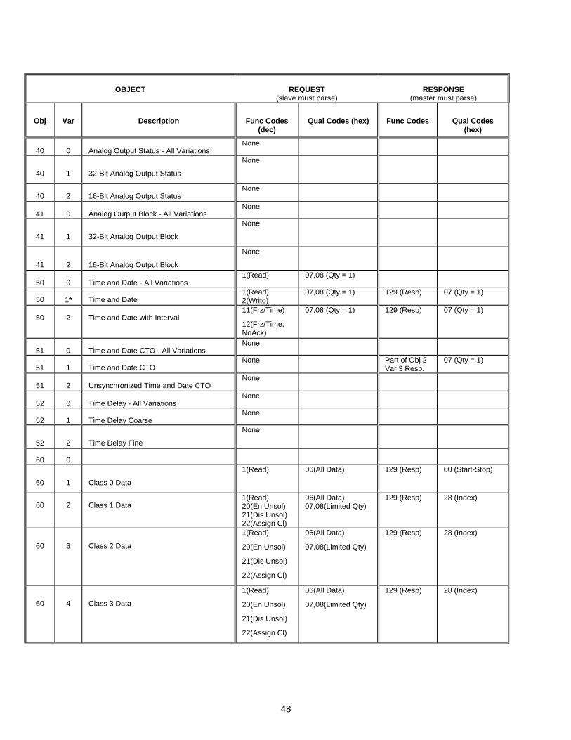
48
OBJECT
REQUEST
(slave must parse)
RESPONSE
(master must parse)
Obj
Var
Description
Func Codes (dec)
Qual Codes (hex)
Func Codes
Qual Codes (hex)
40
0
Analog Output Status - All Variations
None
40
1
32-Bit Analog Output Status
None
40
2
16-Bit Analog Output Status
None
41
0
Analog Output Block - All Variations
None
41
1
32-Bit Analog Output Block
None
41
2
16-Bit Analog Output Block
None
50
0
Time and Date - All Variations
1(Read) 07,08 (Qty = 1)
50
1*
Time and Date
1(Read) 2(Write)
07,08 (Qty = 1) 129 (Resp) 07 (Qty = 1)
50
2
Time and Date with Interval
11(Frz/Time)
12(Frz/Time, NoAck)
07,08 (Qty = 1) 129 (Resp) 07 (Qty = 1)
51
0
Time and Date CTO - All Variations
None
51
1
Time and Date CTO
None Part of Obj 2 Var 3 Resp.
07 (Qty = 1)
51
2
Unsynchronized Time and Date CTO
None
52
0
Time Delay - All Variations
None
52
1
Time Delay Coarse
None
52
2
Time Delay Fine
None
60
0
60
1
Class 0 Data
1(Read) 06(All Data) 129 (Resp) 00 (Start-Stop)
60
2
Class 1 Data
1(Read) 20(En Unsol) 21(Dis Unsol) 22(Assign Cl)
06(All Data) 07,08(Limited Qty)
129 (Resp)
28 (Index)
60
3
Class 2 Data
1(Read)
20(En Unsol)
21(Dis Unsol)
22(Assign Cl)
06(All Data)
07,08(Limited Qty)
129 (Resp)
28 (Index)
60
4
Class 3 Data
1(Read)
20(En Unsol)
21(Dis Unsol)
22(Assign Cl)
06(All Data)
07,08(Limited Qty)
129 (Resp)
28 (Index)

49
OBJECT
REQUEST
(slave must parse)
RESPONSE
(master must parse)
Obj
Var
Description
Func Codes (dec)
Qual Codes (hex)
Func Codes
Qual Codes (hex)
70
1
File Identifier
None
80
1
Internal Indications
2(Write) 00,01(Start-Stop)
129 (Resp)
Null
81
1
Storage Object
None
82
1
Device Profile
None
83
1
Private Registration Object
None
83
2
Private Registration Object Descriptor
None
90
1
Application Identifier
None
100
1
Short Floating Point
None
100
2
Long Floating Point
None
100
3
Extended Floating Point
None
101
1
Small Packed Binary-Coded Decimal
None
101
2
Medium Packed Binary-Coded Decimal
None
101
3
Large Packed Binary-Coded Decimal
None
No Object (Cold Restart)
13(Cold-Restart)
129 (Resp) Null
No Object (Warm Restart)
14(Warm-Restart)
129 (Resp) Null
No Object (Delay Measurement)
None


