RULES FOR CLASSIFICATION OF DET NORSKE VERITAS Veritasveien 1, NO-1322 Høvik, Norway Tel.: +47 67 57 99 00 Fax: +47 67 57 99 11 SHIPS NEWBUILDINGS SPECIAL EQUIPMENT AND SYSTEMS ADDITIONAL CLASS PART 6 CHAPTER 8 NAUTICAL SAFETY JANUARY 2011 CONTENTS PAGE Sec. 1 General ................................................................................................................................. 8 Sec. 2 Design of Workplace ......................................................................................................... 17 Sec. 3 Workplace Environment .................................................................................................... 44 Sec. 4 Bridge Equipment - Carriage Requirements ...................................................................... 48 Sec. 5 Bridge Equipment - General Requirements ....................................................................... 53 Sec. 6 Bridge Equipment - Specific Requirements ...................................................................... 62 Sec. 7 Network Based Integration of Navigation Systems (ICS) ................................................. 80 Sec. 8 Ship Manoeuvring Characteristics ..................................................................................... 88 Sec. 9 Qualifications and Operational Procedures ....................................................................... 93 Sec. 10 Bridge Equipment - On-board Tests .................................................................................. 95
Transcript
RULES FORCLASSIFICATION OF
SHIPS
NEWBUILDINGS
SPECIAL EQUIPMENT AND SYSTEMSADDITIONAL CLASS
PART 6 CHAPTER 8
NAUTICAL SAFETYJANUARY 2011
CONTENTS PAGE
Sec. 1 General................................................................................................................................. 8Sec. 2 Design of Workplace ......................................................................................................... 17Sec. 3 Workplace Environment .................................................................................................... 44Sec. 4 Bridge Equipment - Carriage Requirements...................................................................... 48Sec. 5 Bridge Equipment - General Requirements....................................................................... 53Sec. 6 Bridge Equipment - Specific Requirements ...................................................................... 62Sec. 7 Network Based Integration of Navigation Systems (ICS) ................................................. 80Sec. 8 Ship Manoeuvring Characteristics..................................................................................... 88Sec. 9 Qualifications and Operational Procedures ....................................................................... 93Sec. 10 Bridge Equipment - On-board Tests .................................................................................. 95
DET NORSKE VERITASVeritasveien 1, NO-1322 Høvik, Norway Tel.: +47 67 57 99 00 Fax: +47 67 57 99 11
CHANGES IN THE RULES
GeneralThe present edition of the rules includes amendments and additions approved by the Executive Committee as of November2010 and supersedes the July 2010 edition of the same chapter.The rule changes come into force as described below.This chapter is valid until superseded by a revised chapter.
Main changes coming into force 1 January 2011• Sec.1 General— Table C1 Document requirements is updated.
• Sec.6 Bridge Equipment - Specific Requirements— J100: Internal communication equipment is totally amended.
Corrections and ClarificationsIn addition to the above stated rule requirements, a number of corrections and clarifications have been made to the existingrule text.
Any comments may be sent by e-mail to [email protected] subscription orders or information about subscription terms, please use [email protected] Typesetting (Adobe Frame Maker) by Det Norske Veritas
If any person suffers loss or damage which is proved to have been caused by any negligent act or omission of Det Norske Veritas, then Det Norske Veritas shall pay compensation tosuch person for his proved direct loss or damage. However, the compensation shall not exceed an amount equal to ten times the fee charged for the service in question, provided thatthe maximum compensation shall never exceed USD 2 million.In this provision "Det Norske Veritas" shall mean the Foundation Det Norske Veritas as well as all its subsidiaries, directors, officers, employees, agents and any other acting on behalfof Det Norske Veritas.
Rules for Ships, January 2011 Pt.6 Ch.8 Contents – Page 3
CONTENTS
Sec. 1 General ................................................................................................................................................ 8
A. Classification................................................................................................................................................................... 8A 100 Application............................................................................................................................................................ 8A 200 Objective ............................................................................................................................................................... 8A 300 The Bridge System................................................................................................................................................ 8A 400 Scope..................................................................................................................................................................... 9A 500 Class Notation and Qualifiers ............................................................................................................................... 9A 600 Class assignment................................................................................................................................................. 10A 700 Structure of the rules........................................................................................................................................... 10
B. Definitions..................................................................................................................................................................... 10B 100 Terms and abbreviations ..................................................................................................................................... 10
C. Documentation .............................................................................................................................................................. 13C 100 General................................................................................................................................................................ 13
Sec. 2 Design of Workplace ........................................................................................................................ 17
A. General .......................................................................................................................................................................... 17A 100 Scope................................................................................................................................................................... 17A 200 Application.......................................................................................................................................................... 17
B. Bridge Design ............................................................................................................................................................... 17B 100 Principal requirements ........................................................................................................................................ 17B 200 Field-of-vision from within the wheelhouse....................................................................................................... 17B 300 Field-of-vision from workstations ...................................................................................................................... 18B 400 Blind sectors ....................................................................................................................................................... 22B 500 Bridge windows .................................................................................................................................................. 23B 600 Arrangements for clear view through bridge windows ...................................................................................... 25B 700 Bridge configuration ........................................................................................................................................... 25
C. Wheelhouse Arrangement and Workstation Configuration.......................................................................................... 26C 100 General requirements .......................................................................................................................................... 26C 200 Passageways........................................................................................................................................................ 28C 300 Console configuration......................................................................................................................................... 28C 400 Chairs .................................................................................................................................................................. 29C 500 Wheelhouse surveillance system ........................................................................................................................ 29
D. Workstations for Primary Bridge Functions - Location of Equipment......................................................................... 30D 100 General................................................................................................................................................................ 30D 200 Locating equipment - “within reach” and “easily readable” .............................................................................. 30D 300 Workstations for monitoring and navigating & manoeuvring............................................................................ 31D 400 Workstation for monitoring ................................................................................................................................ 32D 500 Workstation for navigating & manoeuvring ....................................................................................................... 33D 600 Workstations for conning.................................................................................................................................... 35D 700 Workstation for voyage planning........................................................................................................................ 36D 800 Workstations for manual steering ....................................................................................................................... 36D 900 Workstation for emergency steering................................................................................................................... 37D 1000 Workstation for safety monitoring...................................................................................................................... 37D 1100 Workstations for docking operations .................................................................................................................. 38D 1200 Workstations for GMDSS .................................................................................................................................. 40
E. Additional Workstations .............................................................................................................................................. 40E 100 Additional functions assigned the OOW ........................................................................................................... 40E 200 Other functions located on the bridge................................................................................................................. 40
F. Requirements Specific for Class Notation NAUT-AW and/or qualifier (ICS)............................................................ 41F 100 General................................................................................................................................................................ 41F 200 Field-of-vision from workstations ...................................................................................................................... 41F 300 Bridge windows .................................................................................................................................................. 41F 400 Arrangements for clear view through bridge windows....................................................................................... 42F 500 Console configuration......................................................................................................................................... 42F 600 Chairs .................................................................................................................................................................. 42
DET NORSKE VERITAS
Rules for Ships, January 2011 Pt.6 Ch.8 Contents – Page 4
F 700 Workstation for navigating & manoeuvring ....................................................................................................... 42F 800 Workstations for docking operations .................................................................................................................. 42
Sec. 3 Workplace Environment ................................................................................................................. 44
A. General .......................................................................................................................................................................... 44A 100 Scope and application ......................................................................................................................................... 44A 200 General ................................................................................................................................................................ 44
B. Environmental factors ................................................................................................................................................... 44B 100 Vibration ............................................................................................................................................................. 44B 200 Noise ................................................................................................................................................................... 44B 300 Climate control system ....................................................................................................................................... 44
D. Safety of personnel........................................................................................................................................................ 46D 100 General................................................................................................................................................................ 46
Sec. 4 Bridge Equipment - Carriage Requirements................................................................................. 48
A. General .......................................................................................................................................................................... 48A 100 Scope................................................................................................................................................................... 48A 200 Application.......................................................................................................................................................... 48
B. Basic Bridge Equipment ............................................................................................................................................... 48B 100 Steering control systems ..................................................................................................................................... 48B 200 Heading information systems ............................................................................................................................. 48B 300 Speed information systems ................................................................................................................................. 49B 400 Collision Avoidance – decision support systems ............................................................................................... 49B 500 Grounding Avoidance – decision support systems............................................................................................. 50B 600 Weather surveillance systems ............................................................................................................................. 50B 700 Bridge Navigational Watch Alarm System (BNWAS) ...................................................................................... 51B 800 Alarm Management System (AMS) ................................................................................................................... 51B 900 Alarm Transfer System....................................................................................................................................... 51B 1000 Internal Communication Systems....................................................................................................................... 51B 1100 VHF transceivers ................................................................................................................................................ 51
C. Additional Bridge Equipment - NAUT-AW................................................................................................................. 51C 100 Manoeuvring information ................................................................................................................................... 51C 200 Manoeuvring devices .......................................................................................................................................... 51C 300 Speed Over Ground Log ..................................................................................................................................... 51C 400 Radar chart overlay ............................................................................................................................................. 51C 500 Conning information display .............................................................................................................................. 52C 600 Track Control System (TCS) .............................................................................................................................. 52C 700 Training Course .................................................................................................................................................. 52
Sec. 5 Bridge Equipment - General Requirements .................................................................................. 53
A. General .......................................................................................................................................................................... 53A 100 Scope and Application ........................................................................................................................................ 53A 200 Certification ........................................................................................................................................................ 53
B. Location of Equipment.................................................................................................................................................. 53B 100 General................................................................................................................................................................ 53B 200 Antennae ............................................................................................................................................................. 54
C. Electrical Power Supply................................................................................................................................................ 55C 100 Main electrical power supply.............................................................................................................................. 55C 200 Arrangement of UPS........................................................................................................................................... 55
D. Integration and Interfaces.............................................................................................................................................. 56D 100 Circuit integrity................................................................................................................................................... 56D 200 Alarm and warning messages ............................................................................................................................. 56D 300 Data integrity ..................................................................................................................................................... 56D 400 Networks ............................................................................................................................................................ 56
DET NORSKE VERITAS
Rules for Ships, January 2011 Pt.6 Ch.8 Contents – Page 5
E. Human machine interface ............................................................................................................................................. 57E 100 General................................................................................................................................................................ 57E 200 UIDs.................................................................................................................................................................... 58E 300 Indicators and displays........................................................................................................................................ 59E 400 Illumination and lighting of instruments ............................................................................................................ 60E 500 Alarm and warning indicators............................................................................................................................. 60
F. Software ........................................................................................................................................................................ 60F 100 General................................................................................................................................................................ 60
Sec. 6 Bridge Equipment - Specific Requirements................................................................................... 62
A. General .......................................................................................................................................................................... 62A 100 Scope................................................................................................................................................................... 62A 200 Application.......................................................................................................................................................... 62
B. Steering Control Systems.............................................................................................................................................. 62B 100 Manual steering control ...................................................................................................................................... 62B 200 Information and indicators.................................................................................................................................. 63B 300 Heading control system ...................................................................................................................................... 64
C. Heading Information System ........................................................................................................................................ 65C 100 Dual Compass systems ....................................................................................................................................... 65
D. Speed Information System ............................................................................................................................................ 66D 100 Speed Distance Measuring Equipment (SDME) ................................................................................................ 66
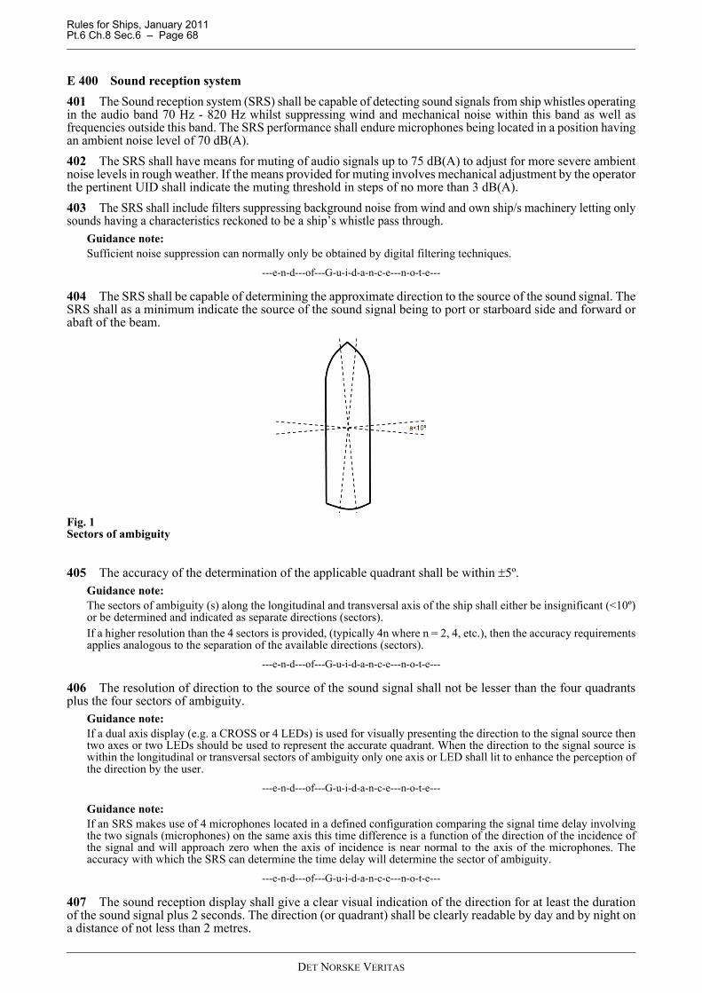
E. Collision Avoidance - Decision Support Systems ........................................................................................................ 66E 100 General................................................................................................................................................................ 66E 200 Radar systems ..................................................................................................................................................... 67E 300 AIS ...................................................................................................................................................................... 67E 400 Sound reception system ...................................................................................................................................... 68
F. Grounding Avoidance - Decision Support Systems .................................................................................................... 69F 100 Electronic chart display and information system (ECDIS)................................................................................. 69F 200 Electronic Position Fixing systems..................................................................................................................... 70F 300 Echo sounding equipment................................................................................................................................... 70
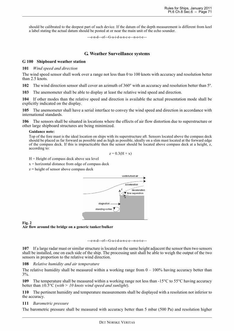
G. Weather Surveillance systems ...................................................................................................................................... 71G 100 Shipboard weather station................................................................................................................................... 71G 200 Weather information system............................................................................................................................... 72
H. Bridge Navigational Watch Alarm System (BNWAS)................................................................................................. 72H 100 Surveillance of the navigational watch ............................................................................................................... 72H 200 Alarm Transfer.................................................................................................................................................... 73
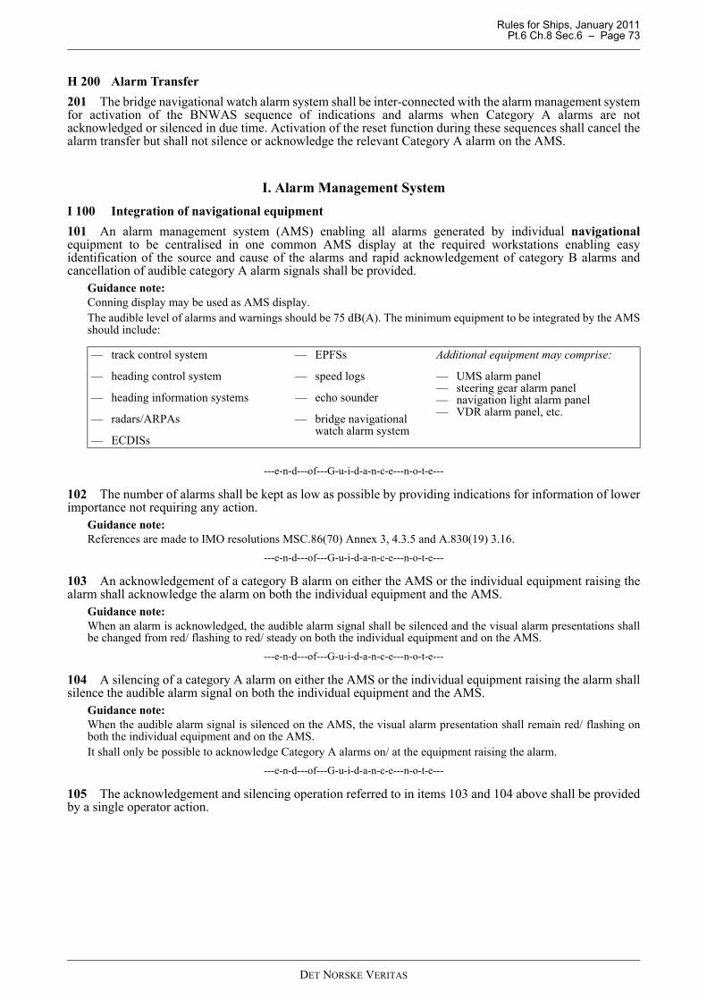
I. Alarm Management System.......................................................................................................................................... 73I 100 Integration of navigational equipment ................................................................................................................ 73
J. Nautical Internal Communication Systems................................................................................................................... 74J 100 Internal communication equipment .................................................................................................................... 74
K. Track control system (TCS) – NAUT-AW................................................................................................................... 76K 100 General ............................................................................................................................................................... 76K 200 Additional Integration......................................................................................................................................... 76K 300 Additional functional requirements ................................................................................................................... 77
L. Conning information display (CID) – NAUT-AW....................................................................................................... 77L 100 General................................................................................................................................................................ 77L 200 Information categories ........................................................................................................................................ 78L 300 Fall-back information ......................................................................................................................................... 79
Sec. 7 Network Based Integration of Navigation Systems (ICS) ............................................................ 80
A. General .......................................................................................................................................................................... 80A 100 Scope................................................................................................................................................................... 80A 200 Applications ........................................................................................................................................................ 80A 300 Objective ............................................................................................................................................................. 80
B. Multi-Function-Displays (MFD)................................................................................................................................... 80B 100 Distribution of functions on workstations .......................................................................................................... 80
C. Human-Machine Interface (HMI) ................................................................................................................................. 81C 100 System Configuration display ............................................................................................................................ 81C 200 Consistent HMI .................................................................................................................................................. 81C 300 Essential information ......................................................................................................................................... 81
DET NORSKE VERITAS
Rules for Ships, January 2011 Pt.6 Ch.8 Contents – Page 6
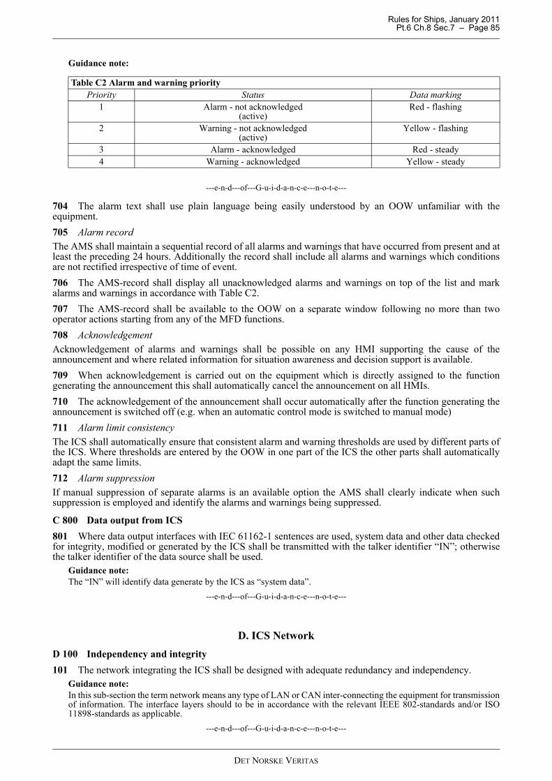
C 400 Accuracy and performance ................................................................................................................................ 82C 500 Integrity monitoring ........................................................................................................................................... 82C 600 Integrity marking ............................................................................................................................................... 83C 700 ICS Alarm management system ......................................................................................................................... 84C 800 Data output from ICS.......................................................................................................................................... 85
D. ICS Network ................................................................................................................................................................. 85D 100 Independency and integrity................................................................................................................................. 85
E. Malfunctions and restoration ........................................................................................................................................ 86E 100 Failure effects...................................................................................................................................................... 86E 200 Orderly shut down ............................................................................................................................................. 86E 300 Power interruption ............................................................................................................................................. 87
F. Testing........................................................................................................................................................................... 87F 100 Network test and verification.............................................................................................................................. 87
G. Documentation .............................................................................................................................................................. 87G 100 Network documentation requirements................................................................................................................ 87
H. Quality System.............................................................................................................................................................. 87H 100 Quality assurance ............................................................................................................................................... 87
Sec. 8 Ship Manoeuvring Characteristics ................................................................................................. 88
A. General .......................................................................................................................................................................... 88A 100 Scope................................................................................................................................................................... 88A 200 Application.......................................................................................................................................................... 88A 300 Standards ............................................................................................................................................................ 88
B. Trials and Predictions.................................................................................................................................................... 88B 100 General................................................................................................................................................................ 88B 200 Sister ships .......................................................................................................................................................... 89
C. Course-keeping ability ................................................................................................................................................. 89C 100 General................................................................................................................................................................ 89
E. Presentation of Manoeuvring Information .................................................................................................................... 91E 100 Wheelhouse poster .............................................................................................................................................. 91E 200 Manoeuvring booklet .......................................................................................................................................... 91E 300 Pilot card ............................................................................................................................................................. 91
Sec. 9 Qualifications and Operational Procedures .................................................................................. 93
A. General .......................................................................................................................................................................... 93A 100 Introduction......................................................................................................................................................... 93A 200 Scope................................................................................................................................................................... 93A 300 Application.......................................................................................................................................................... 93
B. Watch keeping arrangement.......................................................................................................................................... 93B 100 Operational assumptions..................................................................................................................................... 93
C. Qualifications ................................................................................................................................................................ 93C 100 General................................................................................................................................................................ 93
D. Bridge Watch Procedures.............................................................................................................................................. 94D 100 Procedures for safe watch-keeping ..................................................................................................................... 94
Sec. 10 Bridge Equipment - On-board Tests .............................................................................................. 95
A. General .......................................................................................................................................................................... 95A 100 Application.......................................................................................................................................................... 95
DET NORSKE VERITAS
Rules for Ships, January 2011 Pt.6 Ch.8 Contents – Page 7
B. On board Testing of Bridge Equipment ........................................................................................................................ 95B 100 General................................................................................................................................................................ 95B 200 Test preparations................................................................................................................................................. 95B 300 General requirements for the testing of bridge equipment ................................................................................. 95B 400 Gyro compass ..................................................................................................................................................... 95B 500 Heading control system ...................................................................................................................................... 96B 600 Rudder indicator(s) ............................................................................................................................................. 96B 700 Rate-of-turn indicator.......................................................................................................................................... 96B 800 Speed log............................................................................................................................................................. 96B 900 Echo sounder....................................................................................................................................................... 96B 1000 Radar system....................................................................................................................................................... 96B 1100 ARPA system...................................................................................................................................................... 97B 1200 Electronic position-fixing systems...................................................................................................................... 97B 1300 Bridge watch surveillance system....................................................................................................................... 97B 1400 Alarm management system................................................................................................................................. 97B 1500 Communication systems ..................................................................................................................................... 97B 1600 Sound reception system ...................................................................................................................................... 97B 1700 Electronic chart display and information system (ECDIS)................................................................................. 97B 1800 Track control System (TCS) ............................................................................................................................... 97B 1900 Conning display .................................................................................................................................................. 98B 2000 Weather information system............................................................................................................................... 98
DET NORSKE VERITAS
Rules for Ships, January 2011 Pt.6 Ch.8 Sec.1 – Page 8
SECTION 1 GENERAL
A. ClassificationA 100 Application101 The requirements of this chapter apply to bridge design, workstation arrangement and installation ofnavigational equipment and provision of manoeuvring documentation on seagoing vessels.
A 200 Objective201 The objective of the rules for nautical safety is to reduce the risk of collision, grounding and heavyweather damage through enhancement of the reliability of the Bridge System.
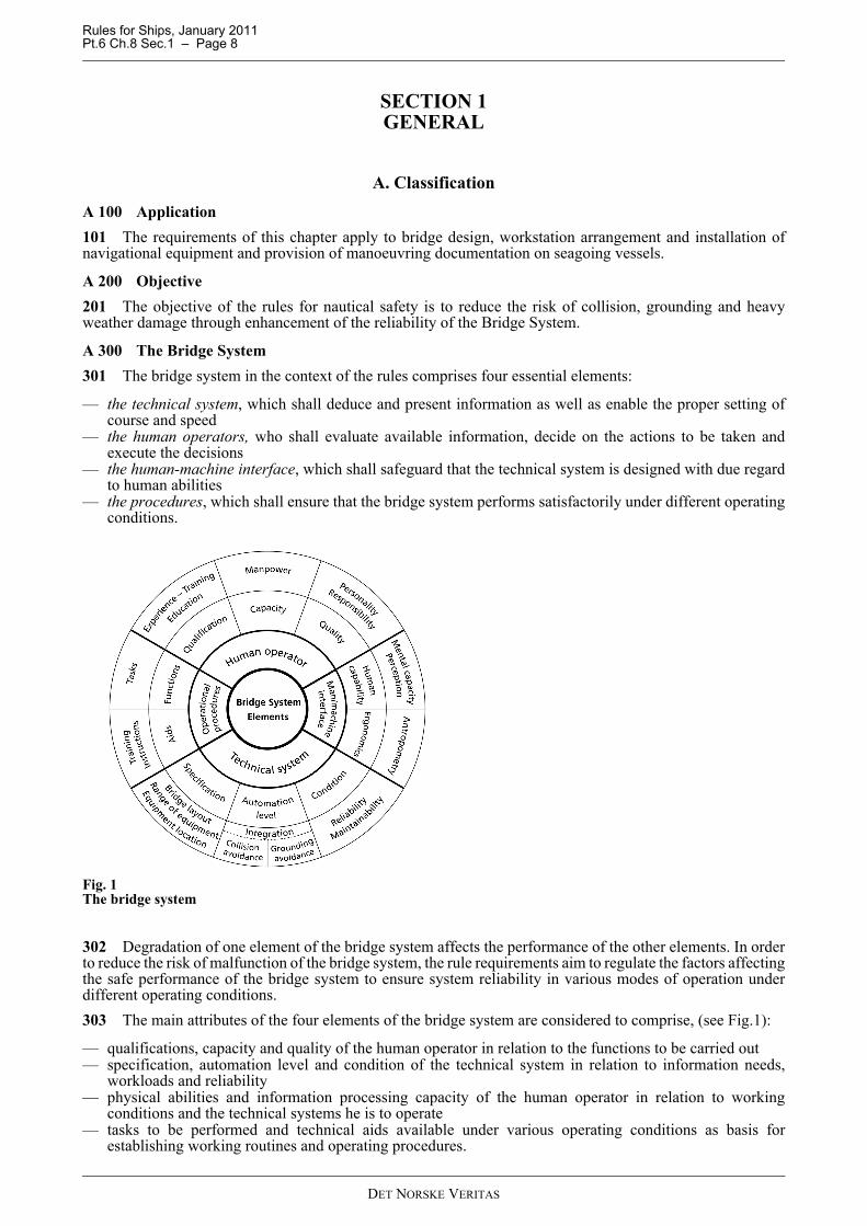
A 300 The Bridge System301 The bridge system in the context of the rules comprises four essential elements:
— the technical system, which shall deduce and present information as well as enable the proper setting ofcourse and speed
— the human operators, who shall evaluate available information, decide on the actions to be taken andexecute the decisions
— the human-machine interface, which shall safeguard that the technical system is designed with due regardto human abilities
— the procedures, which shall ensure that the bridge system performs satisfactorily under different operatingconditions.
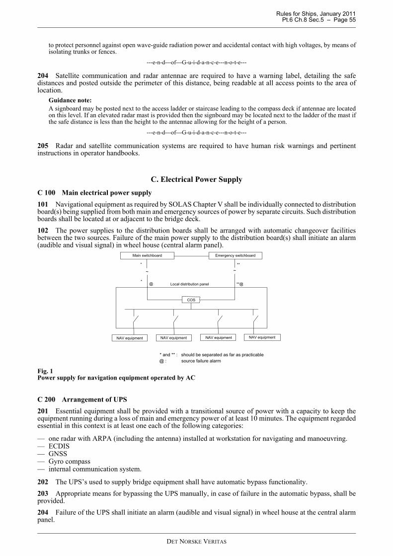
Fig. 1The bridge system
302 Degradation of one element of the bridge system affects the performance of the other elements. In orderto reduce the risk of malfunction of the bridge system, the rule requirements aim to regulate the factors affectingthe safe performance of the bridge system to ensure system reliability in various modes of operation underdifferent operating conditions.303 The main attributes of the four elements of the bridge system are considered to comprise, (see Fig.1):
— qualifications, capacity and quality of the human operator in relation to the functions to be carried out— specification, automation level and condition of the technical system in relation to information needs,
workloads and reliability— physical abilities and information processing capacity of the human operator in relation to working
conditions and the technical systems he is to operate— tasks to be performed and technical aids available under various operating conditions as basis for
establishing working routines and operating procedures.
DET NORSKE VERITAS
Rules for Ships, January 2011 Pt.6 Ch.8 Sec.1 – Page 9
304 With the exception of operator qualifications and quality, which are considered to be a matter of selectionof personnel, the attributes mentioned in 303 forms the basis of these rule requirements. It is recognized thatimprovements of the attributes mentioned will have a positive effect on the performance of the human element.
A 400 Scope401 The requirements are established on the supposition that the regulations of international conventions andthe rules for main class are complied with.402 Within the operational limits of the applicable class notation the rules aim to safeguard that the officerof the navigational watch has full control of all the primary functions he/she is responsible for, including thelook out function required by COLREGS72, single-handed. 403 Moreover, the rules acknowledge that the modes of operation and the manning of the bridge varies inaccordance with internal and external conditions like availability of technical systems, type of waters, trafficdensity and weather conditions. The rules therefore aim to provide a bridge arrangement being suitable for anenlarged bridge team when operational or legislative conditions so requires.
Guidance note:The actual manning of the navigational watch shall at all times be in accordance with the regulations of the flag stateas well as for the waters in which the ship is operating. This is considered the responsibility of the master of the shipand the officer of the navigational watch.
---e-n-d---of---G-u-i-d-a-n-c-e---n-o-t-e---
404 The rules stipulate requirements for the following areas aiming to manage the risk of bridge systemfailures:
— design of workplace, based on analyses of functions to be performed under various operating conditionsand the technical aids to be installed
— bridge working environment, based on factors affecting the performance of human operators— range of instrumentation, based on information needs and efficient performance of navigational tasks— equipment reliability applicable to all types of bridge equipment, based on common requirements to ensure
their suitability under various environmental conditions— performance of different types of bridge equipment, based on their specific functions— human-machine interface, based on analyses of human limitations and compliance with ergonomic
principles— information on the ship’s manoeuvring characteristics, based on the competence needed for safe
performance of operations involving ship manoeuvring — tests and trials based on the need to ensure that technical systems perform in accordance with their approved
specifications before being relied upon and used in practical operation— and give guidance concerning qualifications essential for mastering the navigational systems installed.
405 The reliability and availability of equipment and systems for steering and propulsion, although essentialfor safe navigation, is addressed by the rules of main class. The scope of this chapter concerning suchequipment is:
— the location and arrangement in the wheelhouse— the human-machine interface— any integration and/or interface with navigational equipment.
406 The scope of this chapter concerning systems and equipment being additional to those related to safetyof navigation, but important to the safety or security of the ship, such as cargo/ballast system, safety monitoringsystems, fire systems, GMDSS equipment, security equipment, hull monitoring system, and similar systems is:
— the location and arrangement in the wheelhouse— the noise and illumination level— any integration and/or interface with navigational equipment.
407 On ships fitted with an Integrated Navigation System involving automatic control of heading and/orspeed The Bridge System is only considered compliant with the code of safe navigation when the officer of thenavigational watch holds a certificate of competence in accordance with the requirements of Sec.9.
A 500 Class Notation and Qualifiers501 Vessels built and tested in compliance with the requirements of this chapter, or chapter 20 and therequirements of the rules for main class may be assigned class notation NAUT and qualifiers as given inTable A1.502 In order to offer classification that meets the individual needs of ship operators, related to different types
DET NORSKE VERITAS
Rules for Ships, January 2011 Pt.6 Ch.8 Sec.1 – Page 10
and trades of ships, the rules are divided into three class notations, NAUT-OC, NAUT-AW and NAUT-OSV.
Guidance note:Example of notations with qualifier: NAUT-OC (ICS).
---e-n-d---of---G-u-i-d-a-n-c-e---n-o-t-e---
503 Ships which have waived one or more of the requirements recognized by the rules as being applicablefor ships in world wide trade only shall have the following additional text entered in the “Appendix to theclassification certificate”:
— the class notation has been granted on the said agreement that the vessel will only operate in < insert the area/waters to be traded and any other conditions of the waiver >.
Guidance note:Example: The class notation has been granted on the said agreement that the vessel will only operate in Europeanwaters fully covered by ENC.
---e-n-d---of---G-u-i-d-a-n-c-e---n-o-t-e---
A 600 Class assignment601 The ship will be assigned class notation NAUT-OC when the relevant requirements given in Sec.1 toSec.6 and Sec.10 are complied with.602 The ship will be assigned class notation NAUT-AW when the relevant requirements given in Sec.1 toSec.6 and Sec.8 and Sec.10 are complied with.603 The class notation may upon request be extended with a qualifier (ICS) when the requirements in Sec.7are complied with.
A 700 Structure of the rules701 The rule structure establishes functional requirements to the greatest extent possible and gives guidanceas to how a functional requirement can be met in the course of a technical solution.702 A functional requirement is as far as possible expressed without quantification. The functionalrequirements have a principle status and will only be adjusted if the functions to be carried out on the bridgeare altered.
B. Definitions
B 100 Terms and abbreviations101 Abnormal operating conditions: When malfunction of technical system(s) requires operation of backupsystems on the bridge, or if malfunction occurs during an irregular operating condition, or when the officer ofthe watch becomes unfit to perform his duties and has not yet been replaced by another qualified officer.
Table A1 Class notations and qualifiersClass notation Description Qualifier Description Design
requirements, rule reference
Survey requirements, rule reference
NAUT
Requirements within bridge design, bridge instrumentation, and workstation arrangement.
OCFundamental requirements targeting ships largely operating on the high seas
Sec.2
Pt.7 Ch.1 Sec.6
AW
- augmented requirements for bridge configuration, instrumentation and automation and including detailed documentation of the manoeuvring characteristics of the ship.-targeting ships largely operating in coastal and narrow waters
Sec.2
OSVSee Chapter 20 for details.- targeting ships largely operating as support vessel for various offshore operations
Pt.6 Ch.20
(ICS)a multifunction workstation arrangement supporting the navigational functions of NAUT-nn by means of network technology
Sec.7
DET NORSKE VERITAS
Rules for Ships, January 2011 Pt.6 Ch.8 Sec.1 – Page 11
102 Additional bridge functions: Functions related to ship operations which are to be carried out on the bridge in addition to primary functions,and whether or not the OOW is responsible for the allocated tasks. Examples of such functions are:
— extended communication functions— monitoring and control of ballasting and cargo operations— monitoring and control of machinery— monitoring and control of domestic systems.
103 Back-up navigator: A navigational officer who has been designated by the ship’s master to be on call ifassistance is needed on the bridge.104 Blackout period: The period suffering loss of electric power from the main and emergency generatingplants.105 Blind sector: An obstruction of the sea surface situated within a required field of vision sector.106 Bridge: The area from which the navigation and control of the ship are exercised, comprising thewheelhouse and the bridge wings.107 Bridge system: The total system governing the performance of bridge functions, comprising bridgepersonnel, technical systems, human-machine interface and procedures.108 Bridge wing: The part of the bridge on each side of the wheelhouse, which extends towards the ship’sside.109 Category A alarm: alarm where graphical e.g. radar, ECDIS, information at the task station directlyassigned to the function generating the alarm is necessary, as decision support for the evaluation the alarmrelated condition.Category A alarms should include alarms indicating:
— danger of collision— danger of grounding.
110 Category B alarm: Alarm where no additional information for decision support is necessary besides theinformation which can be presented at the alarm management panel/ screen. Category B alarms are all alarmsnot falling under Category A.111 Catwalk: A narrow, usually elevated platform arrangement outside the wheelhouse allowing a personsafe access to windows along the front bulkhead(s).112 Coastal waters: Deep unobstructed waters along a coastline that is extending an equivalent distance ofnot less than 30 minutes sailing at the relevant speed in all directions to one side of the course line (oppositethe coastline).113 Collision avoidance functions. Monitoring surrounding traffic and other objects visually and by allappropriate means to determine dangers of collisions, pertinent responsibilities in accordance with COLREG,and execute measures to steer clear of the danger.114 Commanding view: View without obstructions, which could interfere with the navigator’s ability toperform his main tasks, at least covering the field of vision required for safe performance of collision avoidancefunctions.115 Conning information display: A screen-based information system centralizing ship’s control stateparameters, system set/order values and voyage plan data.116 Conning station or position. Place in the wheelhouse with a commanding view providing the necessaryinformation for conning, and which is used by navigators, including pilots, when monitoring and directing theship’s movements.117 Docking operations: Manoeuvring the ship alongside a berth and supervising the mooring operations.118 Easily accessible: Being both perceptible from and located within 5 m distance from the relevantworking position.119 Easily readable: see Sec.2 D203.120 EPFS: Electronic Position Fixing System121 Emergency situations: When incidents affect regular operating conditions and priorities due to gravethreats against the ship’s safety, integrity or security. 122 Ergonomics: The scientific discipline concerned with designing according to the human needs, and theprofession that applies theory, principles, data and methods to design in order to optimize human well-being
DET NORSKE VERITAS
Rules for Ships, January 2011 Pt.6 Ch.8 Sec.1 – Page 12
and overall system performance.123 Failure Modes and Effects Analysis (FMEA:) is an engineering method of analysis of potential failuremodes within a system to determine the impact that failures, errors and defects in components on sub-systemlevel may have on the larger system.124 Field of vision. Angular size of scenery being observable from a position within the ship’s bridge.125 Grounding avoidance function: Monitor the ship’s position in relation to the voyage plan, and determineand execute course alterations to make the ship follow the planned track.126 Helmsman: Designated person who actuates the rudder and control the heading of the ship under way.127 HMI: Human Machine Interface.128 ICS: Network based integration of navigation system.129 Irregular operating conditions: When external conditions cause excessive operator workloads.130 Manoeuvring: Operation of steering and propulsion machinery, as required to alter the ship’s heading,speed and/or directional movement.131 MFD: Multi-Function-Display. A screen (and pertinent computer) configured for the display of severalapplications/functions (e.g. ECDIS, ARPA, AMS).132 MKD (AIS): AIS Minimum Keyboard and Display.133 Monitoring: Act of constantly checking information from instrument displays and environment in orderto detect any irregularities.134 Narrow waters: Waters with restricted freedom of course setting and where pilotage conventionally isthe foremost navigational method.135 Navigation: is the process of planning, reading, and controlling the movement of a ship from one placeto another.136 Normal operating conditions: When all shipboard systems and equipment related to primary bridgefunctions operate within design limits, and weather conditions or traffic, do not cause excessive operatorworkloads.137 Ocean areas: Waters that encompass navigation beyond the outer limits of coastal waters. Ocean areasdo not restrict the freedom of course setting in any direction for a distance equivalent to 30 minutes of sailingwith the relevant ship speed.138 Officer of the navigational watch: Person responsible for the safety of navigation and bridge operations.139 OOW: Officer of the navigational watch.140 Primary bridge functions. Functions related to determination, execution and maintenance of safe course,speed and position of the ship in relation to the waters, traffic and weather conditions. Such functions are:
— voyage planning functions— navigation functions— collision avoidance functions— manoeuvring functions— docking functions— monitoring of internal safety systems— external and internal communication related to safety in bridge operation and distress situations.
141 SOG: Speed Over Ground; - ship’s real time speed measured relative earth surface.142 STW: Speed Through Water; - ship’s real time speed measured relative water surface.143 SMG: Speed Made Good; - ship’s reckoned speed between two positions determined “a posteriori”.144 Superstructure: Decked structure, not including funnels, which is on or above the freeboard deck.145 UID: User Input Device; (example: keyboard, tiller, joystick, helm, pushbutton, etc.).146 Voyage plan: a comprehensive, berth to berth guide, developed and used by the vessel’s bridge team todetermine the most favourable passage, to identify hazards along the track, and to make out the bridge teammanagement to ensure the vessel’s safe passage.147 Voyage planning: gathering information relevant to the contemplated voyage; the plotting of course linesand turn radii of the intended voyage in appropriate charts: indication of areas of danger, existing ships'routeing and reporting systems, vessel traffic services, areas involving marine environmental protectionconsiderations and safe speed.
DET NORSKE VERITAS
Rules for Ships, January 2011 Pt.6 Ch.8 Sec.1 – Page 13
148 Wheelhouse: Enclosed area of the bridge.149 Wheel-over-line The line parallel to the next course line that is passing through the point where the rudderorder has to be initiated for the ship to accurately follow a curved track with a fixed radius.150 Wheel-over-point. The point where the ship has to initiate a rudder order in order to accurately follow acurved track, taking into consideration the distance required for the ship to build up the necessary turn rate.151 Within reach: see Sec.2 D200.152 Workstation: A workplace at which one or several tasks constituting a particular activity are carried out,designed, arranged and located as required to provide the information, systems and equipment required for safeand efficient performance of dedicated tasks and bridge team co-operations.
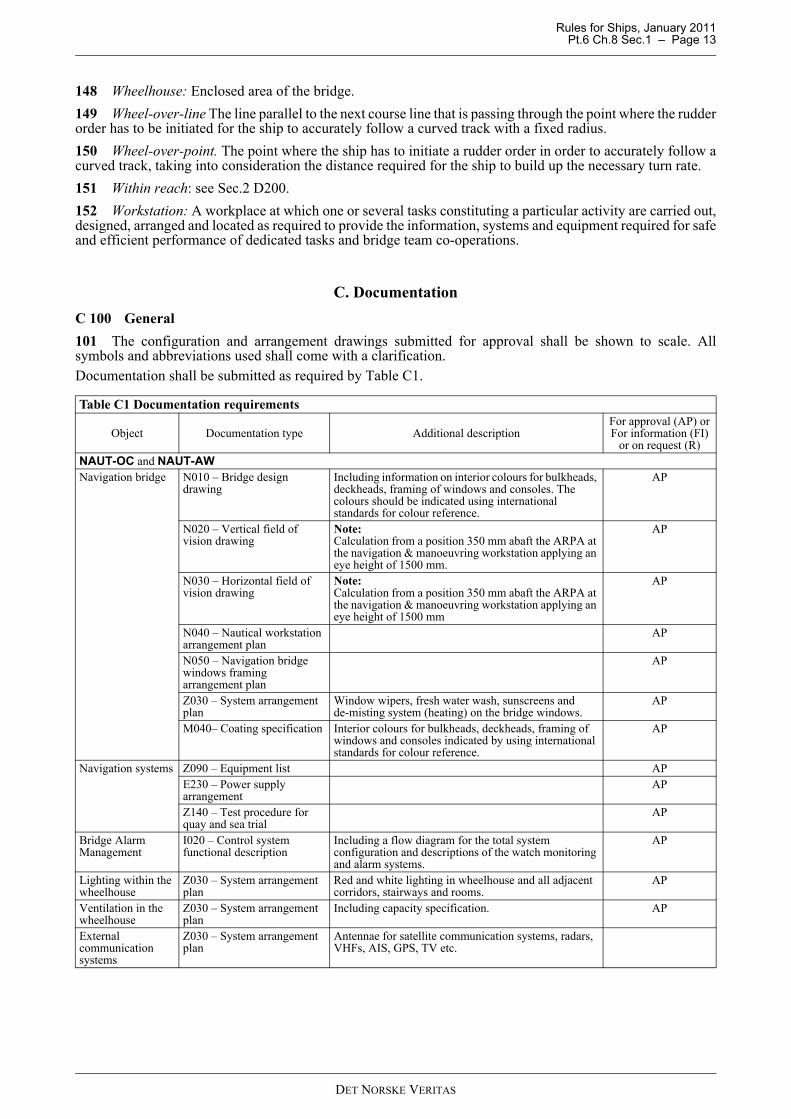
C. DocumentationC 100 General101 The configuration and arrangement drawings submitted for approval shall be shown to scale. Allsymbols and abbreviations used shall come with a clarification.Documentation shall be submitted as required by Table C1.
Table C1 Documentation requirements
Object Documentation type Additional descriptionFor approval (AP) orFor information (FI)
or on request (R)NAUT-OC and NAUT-AWNavigation bridge N010 – Bridge design
drawingIncluding information on interior colours for bulkheads, deckheads, framing of windows and consoles. The colours should be indicated using international standards for colour reference.
AP
N020 – Vertical field of vision drawing
Note:Calculation from a position 350 mm abaft the ARPA at the navigation & manoeuvring workstation applying an eye height of 1500 mm.
AP
N030 – Horizontal field of vision drawing
Note: Calculation from a position 350 mm abaft the ARPA at the navigation & manoeuvring workstation applying an eye height of 1500 mm
AP
N040 – Nautical workstation arrangement plan
AP
N050 – Navigation bridge windows framing arrangement plan
AP
Z030 – System arrangement plan
Window wipers, fresh water wash, sunscreens and de-misting system (heating) on the bridge windows.
AP
M040– Coating specification Interior colours for bulkheads, deckheads, framing of windows and consoles indicated by using international standards for colour reference.
AP
Navigation systems Z090 – Equipment list APE230 – Power supply arrangement
AP
Z140 – Test procedure for quay and sea trial
AP
Bridge Alarm Management
I020 – Control system functional description
Including a flow diagram for the total system configuration and descriptions of the watch monitoring and alarm systems.
AP
Lighting within the wheelhouse
Z030 – System arrangement plan
Red and white lighting in wheelhouse and all adjacent corridors, stairways and rooms.
AP
Ventilation in the wheelhouse
Z030 – System arrangement plan
Including capacity specification. AP
External communication systems
Z030 – System arrangement plan
Antennae for satellite communication systems, radars, VHFs, AIS, GPS, TV etc.
DET NORSKE VERITAS
Rules for Ships, January 2011 Pt.6 Ch.8 Sec.1 – Page 14
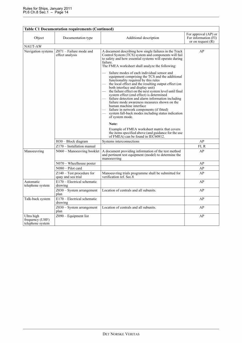
NAUT-AWNavigation systems Z071 – Failure mode and
effect analysisA document describing how single failures in the Track Control System (TCS) system and components will fail to safety and how essential systems will operate during failure. The FMEA worksheet shall analyze the following:
— failure modes of each individual sensor and equipment comprising the TCS and the additional functionality required by this rules
— the local effect and the resulting output effect (on both interface and display unit)
— the failure effect on the next system level until final system effect (end effect) is determined
— failure detection and alarm information including failure mode awareness measures shown on the human machine interface
— failure in network components (if fitted)— system fall-back modes including status indication
of system mode.
Note:Example of FMEA worksheet matrix that covers the items specified above (and guidance for the use of FMEA) can be found in IEC60812.
AP
I030 – Block diagram Systems interconnections APZ170 – Installation manual FI, R
Manoeuvring N060 – Manoeuvring booklet A document providing information of the test method and pertinent test equipment (model) to determine the manoeuvring
AP
N070 – Wheelhouse poster APN080 – Pilot card APZ140 – Test procedure for quay and sea trial
Manoeuvring trials programme shall be submitted for verification ref. Sec.8
AP
Automatic telephone system
E170 – Electrical schematic drawing
AP
Z030 – System arrangement plan
Location of centrals and all subunits. AP
Talk-back system E170 – Electrical schematic drawing
AP
Z030 – System arrangement plan
Location of centrals and all subunits. AP
Ultra high frequency (UHF) telephone system
Z090 – Equipment list AP
Table C1 Documentation requirements (Continued)
Object Documentation type Additional descriptionFor approval (AP) orFor information (FI)
or on request (R)
DET NORSKE VERITAS
Rules for Ships, January 2011 Pt.6 Ch.8 Sec.1 – Page 15
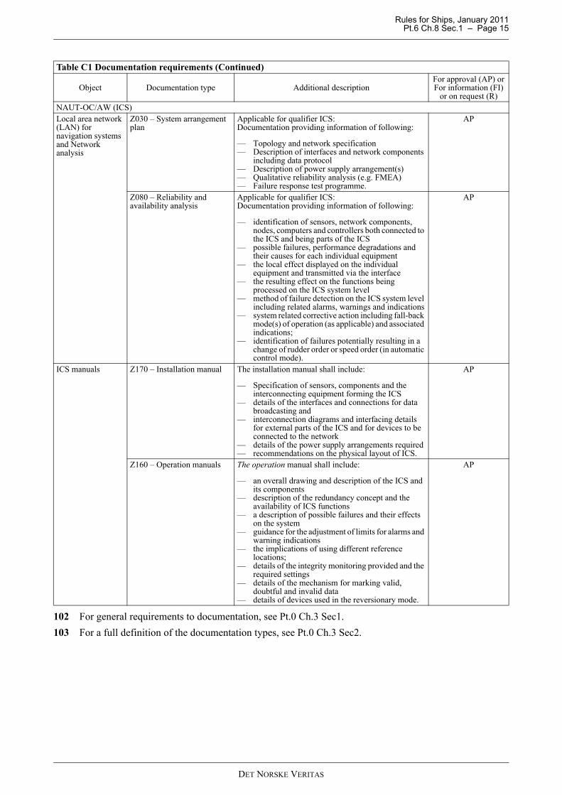
102 For general requirements to documentation, see Pt.0 Ch.3 Sec1.103 For a full definition of the documentation types, see Pt.0 Ch.3 Sec2.
NAUT-OC/AW (ICS)Local area network (LAN) for navigation systems and Network analysis
Z030 – System arrangement plan
Applicable for qualifier ICS:Documentation providing information of following:
— Topology and network specification — Description of interfaces and network components
including data protocol— Description of power supply arrangement(s)— Qualitative reliability analysis (e.g. FMEA)— Failure response test programme.
AP
Z080 – Reliability and availability analysis
Applicable for qualifier ICS:Documentation providing information of following:
— identification of sensors, network components, nodes, computers and controllers both connected to the ICS and being parts of the ICS
— possible failures, performance degradations and their causes for each individual equipment
— the local effect displayed on the individual equipment and transmitted via the interface
— the resulting effect on the functions being processed on the ICS system level
— method of failure detection on the ICS system level including related alarms, warnings and indications
— system related corrective action including fall-back mode(s) of operation (as applicable) and associated indications;
— identification of failures potentially resulting in a change of rudder order or speed order (in automatic control mode).
— Specification of sensors, components and the interconnecting equipment forming the ICS
— details of the interfaces and connections for data broadcasting and
— interconnection diagrams and interfacing details for external parts of the ICS and for devices to be connected to the network
— details of the power supply arrangements required— recommendations on the physical layout of ICS.
AP
Z160 – Operation manuals The operation manual shall include:
— an overall drawing and description of the ICS and its components
— description of the redundancy concept and the availability of ICS functions
— a description of possible failures and their effects on the system
— guidance for the adjustment of limits for alarms and warning indications
— the implications of using different reference locations;
— details of the integrity monitoring provided and the required settings
— details of the mechanism for marking valid, doubtful and invalid data
— details of devices used in the reversionary mode.
AP
Table C1 Documentation requirements (Continued)
Object Documentation type Additional descriptionFor approval (AP) orFor information (FI)
or on request (R)
DET NORSKE VERITAS
Rules for Ships, January 2011 Pt.6 Ch.8 Sec.1 – Page 16
D. TestsD 100 General101 All tests shall be carried out according to test programs approved by the Society.102 The tests and visual examinations shall verify that all relevant rule requirements are met. The tests are tocover requirements given by these rules and applicable IMO performance standards. The test programs shallspecify in detail how the various functions shall be tested and what shall be observed during the tests.
Guidance note:Reference is made to Sec.10 for further information.
---e-n-d---of---G-u-i-d-a-n-c-e---n-o-t-e---
D 200 Track control testing (TCS)201 The TCS testing shall include the entire system integrating all equipment and components and includingthe actual software versions to be installed on board. Serial sensor information may be simulated.202 Failure modes identified by the FMEA shall be simulated as realistically as possible. Prescribed alarmand safety limits shall be checked. Fall-back modes and system status are to be verified.203 It shall be verified that automatic control functions involving course and/or speed changes areperforming satisfactorily within operating limits defined by the set-up of the TCS configuration.
D 300 Testing of network integrity- qualifier (ICS)301 Testing in accordance with Sec.7 F. shall be carried out at the manufacturer’s works as far as practicalin order to limit the necessary testing on board to a minimum.
D 400 On-board testing401 The testing to be completed during installation and commissioning shall include:
a) verification of proper interfacing and data protocol of individual equipmentb) establishment of correct parameters for filters, integrity monitoring, alarm limits, control parameters (time
constants, set points, lengths, heights, etc.)c) verification of correct functionality of system applications and integration of components, including the
ability of the integrated navigation system to keep any controlled process within the specified tolerancesd) verification of fall-back-modes and emergency operation of essential navigational functions.
402 The tests shall demonstrate that the essential navigational functions are available and operable ondesignated back-up means in a situation where the normal navigational system configuration is disabled as faras practical.
D 500 Manoeuvring trials - NAUT-AW501 Tests and trials as required to establish and document the ship's manoeuvring characteristics shall becarried out.
DET NORSKE VERITAS
Rules for Ships, January 2011 Pt.6 Ch.8 Sec.2 – Page 17
SECTION 2 DESIGN OF WORKPLACE
A. General
A 100 Scope
101 This section specifies the requirements for bridge design, including field of vision, -wheelhousearrangement, -workstation configuration and location of equipment within workstations.
A 200 Application
201 Ships requesting class notation NAUT-OC shall comply with the basic rules in B to E.
202 Ships requesting class notation NAUT-AW shall comply with the basic rules in B to E and additionallythe requirements specifically addressing NAUT-AW in these sub-sections.
Guidance note:A requirement being specific for NAUT-AW only is identified by inclusion of the notation in the head line as follows:- Workstations for navigating & manoeuvring – vertical view NAUT-AW.
---e-n-d---of---G-u-i-d-a-n-c-e---n-o-t-e---
203 The requirements being applicable for NAUT-AW only is additionally gathered in sub-section F for easyoverview.
B. Bridge Design
B 100 Principal requirements
101 The ship’s navigation bridge shall enable the OOW to perform navigational duties unassisted at all timesduring normal operating conditions. He shall be able to maintain a proper lookout by sight and hearing as wellas by all available means appropriate in the prevailing circumstances and conditions so as to make full appraisalof the situation and the risk of collision, grounding and other hazards to navigation.
102 The ship’s navigation bridge shall additionally be designed and arranged with the aim of:
— facilitating the tasks to be performed by the bridge team including a pilot in making full appraisal of thesituation and in navigating the ship safely under all operational conditions
— promoting effective and safe bridge resource management— allowing for expeditious, continuous and effective information processing and decision-making by the
bridge team— preventing or minimizing excessive or unnecessary work and any condition or distraction on the bridge
which may cause fatigue or interfere with the vigilance of the bridge team.
103 The bridge design shall meet the terms of all relevant regulations of applicable IMO conventions.Guidance note:Applicable conventions in this respect are the International Convention for Safety Of Life At Sea, the InternationalConvention for Preventing Collisions at Sea and the International Convention on Standards of Training, Certificationand Watch-keeping for Seafarers, as amended.
---e-n-d---of---G-u-i-d-a-n-c-e---n-o-t-e---
B 200 Field-of-vision from within the wheelhouse
201 When designing the bridge, the main factors to be considered are the overall view required from the insideof the wheelhouse and the field of vision required from each workstation.
202 Every effort shall be made to place the bridge above all other decked superstructures in order to obtain thebest possible field of vision for safe navigation and manoeuvring of the ship.
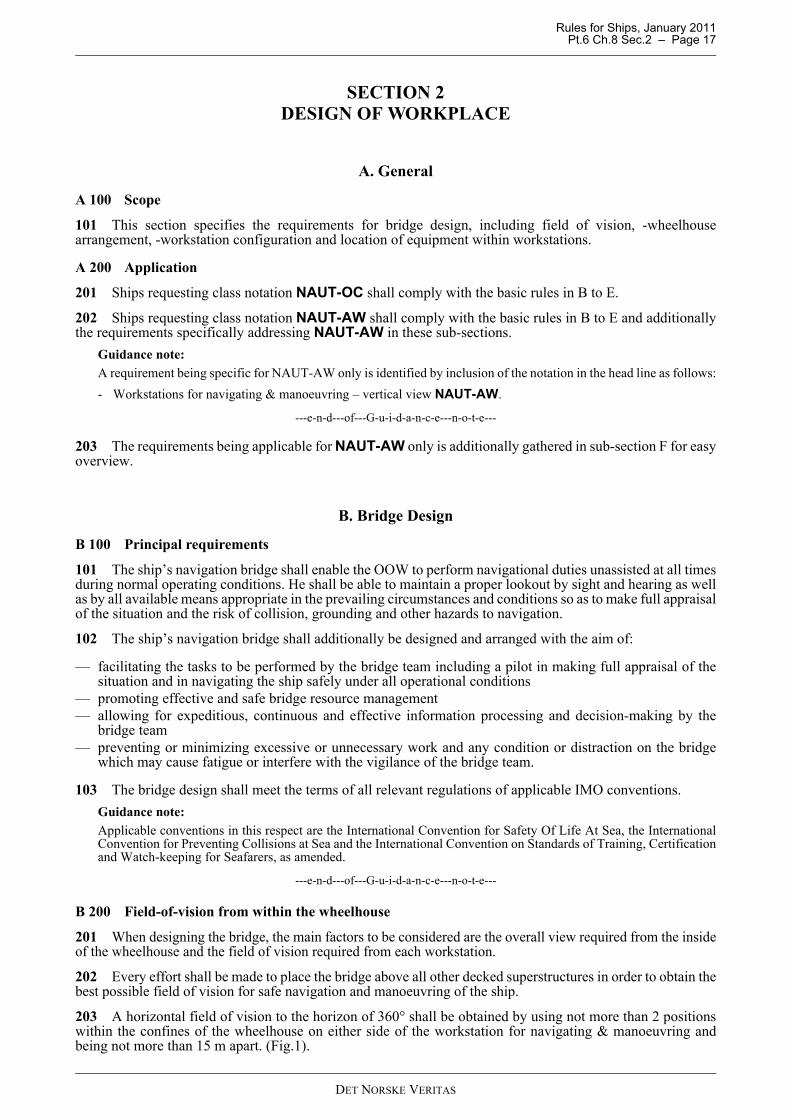
203 A horizontal field of vision to the horizon of 360° shall be obtained by using not more than 2 positionswithin the confines of the wheelhouse on either side of the workstation for navigating & manoeuvring andbeing not more than 15 m apart. (Fig.1).
DET NORSKE VERITAS
Rules for Ships, January 2011 Pt.6 Ch.8 Sec.2 – Page 18
Fig. 1Two positions combined provide ≥ 360° field of vision from inside the wheelhouse
Guidance note:The maximum distance of 15 m between the two positions inside the wheelhouse may be extended, provided thefollowing conditions are fulfilled:- suitable cameras are installed capable of viewing the sector(s) astern not being visible within the required 15 meter
and pertinent displays/monitors are installed being viewable from the workstation for navigating & manoeuvring,and
- the bridge is totally enclosed and the workstations for docking are equipped with appropriate means for course andspeed alterations.
---e-n-d---of---G-u-i-d-a-n-c-e---n-o-t-e---
204 It shall be possible to observe all external objects of interest for safe navigation, such as ships, buoys andlighthouses in any direction from inside the wheelhouse when the ship is pitching and rolling (eye height 1800mm).
Guidance note:Irrespective of helicopter decks or other structures placed on top of the wheelhouse a vertical angle of view of not lessthan 5° above a horizontal line extending from eye height in standing position shall be available all through the 360ºhorizontal field of vision when positioned adjacent the windows. The eye height in a standing position is consideredto be at least 1800 mm above the deck surface for this purpose.
---e-n-d---of---G-u-i-d-a-n-c-e---n-o-t-e---
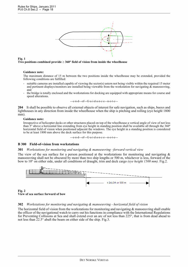
B 300 Field-of-vision from workstations301 Workstations for monitoring and navigating & manoeuvring –forward vertical view The view of the sea surface for a person positioned at the workstations for monitoring and navigating &manoeuvring shall not be obscured by more than two ship lengths or 500 m, whichever is less, forward of thebow to 10° on either side, under all conditions of draught, trim and deck cargo (eye height 1500 mm). Fig.2.
Fig. 2View of sea surface forward of bow
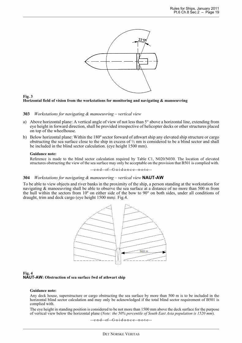
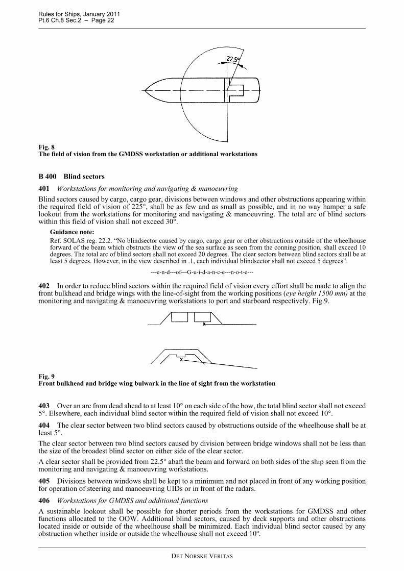
302 Workstations for monitoring and navigating & manoeuvring - horizontal field of visionThe horizontal field of vision from the workstations for monitoring and navigating & manoeuvring shall enablethe officer of the navigational watch to carry out his functions in compliance with the International Regulationsfor Preventing Collisions at Sea and shall extend over an arc of not less than 225°, that is from dead ahead tonot less than 22.5° abaft the beam on either side of the ship. Fig.3.
DET NORSKE VERITAS
Rules for Ships, January 2011 Pt.6 Ch.8 Sec.2 – Page 19
Fig. 3Horizontal field of vision from the workstations for monitoring and navigating & manoeuvring
303 Workstations for navigating & manoeuvring – vertical view
a) Above horizontal plane: A vertical angle of view of not less than 5° above a horizontal line, extending fromeye height in forward direction, shall be provided irrespective of helicopter decks or other structures placedon top of the wheelhouse.
b) Below horizontal plane: Within the 180º sector forward of athwart ship any elevated ship structure or cargoobstructing the sea surface close to the ship in excess of ½ nm is considered to be a blind sector and shallbe included in the blind sector calculation. (eye height 1500 mm).
Guidance note:Reference is made to the blind sector calculation required by Table C1, N020/N030. The location of elevatedstructures obstructing the view of the sea surface may only be acceptable on the provision that B501 is complied with.
---e-n-d---of---G-u-i-d-a-n-c-e---n-o-t-e---
304 Workstations for navigating & manoeuvring – vertical view NAUT-AWTo be able to view objects and river banks in the proximity of the ship, a person standing at the workstation fornavigating & manoeuvring shall be able to observe the sea surface at a distance of no more than 500 m fromthe hull within the sectors from 10º on either side of the bow to 90° on both sides, under all conditions ofdraught, trim and deck cargo (eye height 1500 mm). Fig.4.
Fig. 4NAUT-AW: Obstruction of sea surface fwd of athwart ship
Guidance note:Any deck house, superstructure or cargo obstructing the sea surface by more than 500 m is to be included in thehorizontal blind sector calculation and may only be acknowledged if the total blind sector requirement of B501 iscomplied with.The eye height in standing position is considered to be not more than 1500 mm above the deck surface for the purposeof vertical view below the horizontal plane (Note: the 50% percentile of South East Asia population is 1520 mm).
---e-n-d---of---G-u-i-d-a-n-c-e---n-o-t-e---
DET NORSKE VERITAS
Rules for Ships, January 2011 Pt.6 Ch.8 Sec.2 – Page 20
305 Workstations for navigating & manoeuvring - horizontal view astern NAUT-AWThe navigator shall be able to employ leading lights and marks astern of the ship as visual reference forgrounding avoidance, while seated at the workstation for navigating & manoeuvring. A field of vision sectorastern shall be available and extend over an arc from dead astern to at least 5º on each side. No blind sectorsshall occur within this 10º field of vision sector.
Guidance note:Adequate camera(s) may be accepted for the purpose of achieving the required field of vision astern. The camerasystem and arrangement shall be approved by the Society prior to the installation.Note: Leading lights (or range lights) consist of two lights, separated in distance and elevation, so that when lined upvertically, with one behind the other, they provide a bearing to be used for positioning of the vessel in fairways.
---e-n-d---of---G-u-i-d-a-n-c-e---n-o-t-e---
306 Workstations for navigating & manoeuvring - vertical view astern - NAUT-AWThe vertical view through the aft window pane(s), seen from the workstation for navigating & manoeuvring,shall enable the navigator to view the sea surface in the wake of the ship at a distance not more than 2000 mabaft the stern.The upper edge of the window(s) shall not be less than 2000 mm above bridge deck surface. The maximum height from deck to the lower edge of the window(s) shall be 1000 mm or at least fulfil thefollowing condition:
— the lower part of the window panes shall disclose all obtainable sea surfaces aft of the vessel when viewedfrom the navigating & manoeuvring workstation. Only the superstructure/-deck may be concealed whenviewed from normal operating position at this workstation (eye height 1500 mm).
307 Workstation for conningThe horizontal field of vision from the workstation for conning shall offer a commanding view.The vertical field of view shall enable the conning officer (pilot) to monitor the ship's relative position andleeway in the course of a marked fairway or channel.308 Workstation for docking operationsIn order to enable the navigator(s) to manoeuvre the ship safely alongside a berth and supervise the mooring ofthe ship, the horizontal field of vision from each workstation on the bridge wings shall extend over an arc ofnot less than 225º, that is from at least 45º on the opposite bow through to right astern from the workingposition. Fig.5.
Fig. 5Field of vision from workstations for docking operations
309 The vertical view shall enable the navigators to monitor the ship’s position relative to the berth includingobservation of the accurate distance from the hull side to the quayside (jetty) at sea level from the dockingworkstation.
Guidance note:If B701 cannot be fully satisfied, adequate cameras may be accepted for the purpose of achieving the required verticalview. The camera system and arrangement should be approved by the Society prior to the installation.
---e-n-d---of---G-u-i-d-a-n-c-e---n-o-t-e---
310 Workstation for docking operations - vertical view NAUT-AW
DET NORSKE VERITAS
Rules for Ships, January 2011 Pt.6 Ch.8 Sec.2 – Page 21
The vertical view from the docking workstation shall enable the navigator(s) to observe the “parallel hull side”of both fore ship and stern ship from a standing position besides the console while operating the UIDs on handfor manoeuvring of the ship. The hull’s side plates shall be visible over a total length of not less than L/2 (eyeheight 1500 mm). Fig.6.
Guidance note:Windows should be arranged in the lower part of the bulwark and deck as appropriate to obtain the required verticalview. Alternatively, adequate cameras may be accepted. The camera system and arrangement should be approved by theSociety prior to the installation.
---e-n-d---of---G-u-i-d-a-n-c-e---n-o-t-e---
Fig. 6NAUT-AW: View from docking station (LA+LF) ≥ ½LOA
311 Workstation for manual steeringIn order to enable the helmsman to steer the ship safely in narrow channels, the horizontal field of vision fromthe workstation for manual steering shall extend over an arc from dead ahead to at least 60º on each side. Fig.7.The vertical view shall enable the helmsman to observe steering references in the fore ship (if provided) whilestanding at the normal working position.
Fig. 7The field of vision from workstation for manual steering
312 Workstations for GMDSS and additional functions In order to enable the OOW to operate workstations for safety monitoring, GMDSS equipment and additionalbridge functions for short periods of time, the horizontal field of vision from these workstations shall extend atleast over an arc from 90° on port bow, through forward, to 22.5° abaft the beam on starboard. Fig.8.
DET NORSKE VERITAS
Rules for Ships, January 2011 Pt.6 Ch.8 Sec.2 – Page 22
Fig. 8The field of vision from the GMDSS workstation or additional workstations
B 400 Blind sectors401 Workstations for monitoring and navigating & manoeuvringBlind sectors caused by cargo, cargo gear, divisions between windows and other obstructions appearing withinthe required field of vision of 225°, shall be as few and as small as possible, and in no way hamper a safelookout from the workstations for monitoring and navigating & manoeuvring. The total arc of blind sectorswithin this field of vision shall not exceed 30°.
Guidance note:Ref. SOLAS reg. 22.2. “No blindsector caused by cargo, cargo gear or other obstructions outside of the wheelhouseforward of the beam which obstructs the view of the sea surface as seen from the conning position, shall exceed 10degrees. The total arc of blind sectors shall not exceed 20 degrees. The clear sectors between blind sectors shall be atleast 5 degrees. However, in the view described in .1, each individual blindsector shall not exceed 5 degrees”.
---e-n-d---of---G-u-i-d-a-n-c-e---n-o-t-e---
402 In order to reduce blind sectors within the required field of vision every effort shall be made to align thefront bulkhead and bridge wings with the line-of-sight from the working positions (eye height 1500 mm) at themonitoring and navigating & manoeuvring workstations to port and starboard respectively. Fig.9.
Fig. 9Front bulkhead and bridge wing bulwark in the line of sight from the workstation
403 Over an arc from dead ahead to at least 10° on each side of the bow, the total blind sector shall not exceed5°. Elsewhere, each individual blind sector within the required field of vision shall not exceed 10°.404 The clear sector between two blind sectors caused by obstructions outside of the wheelhouse shall be atleast 5°.The clear sector between two blind sectors caused by division between bridge windows shall not be less thanthe size of the broadest blind sector on either side of the clear sector.A clear sector shall be provided from 22.5° abaft the beam and forward on both sides of the ship seen from themonitoring and navigating & manoeuvring workstations.405 Divisions between windows shall be kept to a minimum and not placed in front of any working positionfor operation of steering and manoeuvring UIDs or in front of the radars.406 Workstations for GMDSS and additional functionsA sustainable lookout shall be possible for shorter periods from the workstations for GMDSS and otherfunctions allocated to the OOW. Additional blind sectors, caused by deck supports and other obstructionslocated inside or outside of the wheelhouse shall be minimized. Each individual blind sector caused by anyobstruction whether inside or outside the wheelhouse shall not exceed 10º.
DET NORSKE VERITAS
Rules for Ships, January 2011 Pt.6 Ch.8 Sec.2 – Page 23
B 500 Bridge windows501 Window height - generalThe minimum height of the upper edge of bridge window panes above the bridge deck surface shall be 2000mm in order to provide a view of the horizon for a person in a standing position at the relevant workingpositions.The maximum height of the lower edge of bridge window panes above the bridge deck shall be 1000 mm inorder to provide view of the nearby sea surface for a person in a sitting position at the workstations.
Guidance note:The maximum height of 1000 mm may be extended, provided the following condition is fulfilled:- the lower part of the window panes shall disclose all obtainable sea surface when viewed from a sitting position at
the most distant workstation (working position). I.e. that only part of the superstructure or deck may be concealedby the extended height as viewed from the most distant workstation (eye height 1500 mm).
---e-n-d---of---G-u-i-d-a-n-c-e---n-o-t-e---
502 Lower edge of front windowsThe navigator shall obtain a good view of the sea surface in the proximity of the ship from dead ahead to 90°on either side of the workstations for navigating & manoeuvring.When the distance between the windows and the viewing point (350 mm aft of the consoles) in sitting positionat the workstations is more than 2300 mm, the height of the lower edge of the windows in the sector from 10°to 90° on each side shall be decreased sufficiently to maintain the line of sight. Fig.10
Fig. 10The height of the lower edge of windows to be decreased when the distance to front bulkhead exceeds 2300 mm
503 Lower edge of front windows - NAUT-AWWhen the distance between the windows and the viewing point 350 mm aft of the consoles in sitting positionsat the workstations for monitoring and navigating & manoeuvring is more than 1500 mm, the height of thelower edge of the windows in the sector from 10° to 90° on each side shall be decreased sufficiently to maintainthe line of sight. Fig.11.
1500 1200 1000
2000
2100
350
930
4002300
750 - 800
DET NORSKE VERITAS
Rules for Ships, January 2011 Pt.6 Ch.8 Sec.2 – Page 24
Fig. 11NAUT-AW: The height of the lower edge of windows to be decreased (lower than 1000 mm) when the distance tofront bulkhead exceeds 1500 mm
504 Window breadthBridge windows should be as large as practicable to sustain a safe lookout and not less than 1200 mm widewithin the field of vision required from the workstations unless otherwise is stated.
Guidance note:The width of the window directly forward of the centre console may be less than 1200 mm in order to avoid divisions/stiffeners being located in front of any workstations.
---e-n-d---of---G-u-i-d-a-n-c-e---n-o-t-e---
505 Window inclinationGlare in bridge windows caused by internal light sources shall be avoided and not impair the view required forconducting a proper lookout. To help avoid reflection (glare) from lights inside the wheelhouse, the bridge frontwindows shall be inclined from the vertical plane top out, at an angle of not less than 15° and not more than25°. Light sources, which may cause reflection in the front windows inclined in accordance with thisrequirement, shall be avoided.506 Side and rear windows shall be inclined from the vertical plane top out at an angle not less than 4°~5° asrequired to avoid glare and specular reflections from instruments and other light sources at the workstations.
Guidance note:Vertical windows may be accepted provided that the installed equipment, lamps etc. do not cause any glare andreflection in the windows.
---e-n-d---of---G-u-i-d-a-n-c-e---n-o-t-e---
507 Enclosed bridge wing windowsFor ships with enclosed bridge wings, it shall be possible to open one side window to view the ship's side at watersurface level if:
— the side windows are vertical and there are no windows in the deck providing a downward view— the side windows are inclined but the bridge wing deck is not extended fully to the maximum width of the
ship.
It shall be possible for one person to open the windows fully. Alternative solutions may be acceptable if theview cannot be achieved by opening windows alone.
Guidance note:An adequate camera system may be acceptable for the purpose of achieving the required view. The camera systemand arrangement should be approved by the Society prior to installation.
---e-n-d---of---G-u-i-d-a-n-c-e---n-o-t-e---
508 Window stiffenersDimension of division between windows shall be kept to a minimum. If stiffeners are to be covered fordecoration this shall not increase the dimensions (width and depth) of the stiffener.
Guidance note:The division between windows, especially within the required field of vision, should not exceed 150 mm. If stiffeners
1500
800
2000
2100
1000
1 500
350
800 400
700
1200
DET NORSKE VERITAS
Rules for Ships, January 2011 Pt.6 Ch.8 Sec.2 – Page 25
are used, the width between window panes should not exceed 100 mm and the depth of the stiffeners should be lessthan 120 mm.
---e-n-d---of---G-u-i-d-a-n-c-e---n-o-t-e---
B 600 Arrangements for clear view through bridge windows 601 From the workstations to be operated by the OOW there shall be a clear view through the bridge windowswithin the required field of vision at all times regardless of weather conditions.The following installations are required:
— To ensure a clear view in conditions of rain and sea spray, heavy duty wipers and fresh water washingsystem shall be provided on all front windows within the field of vision required from the monitoring andnavigating & manoeuvring workstations.
— To improve the visibility and reduce eye strain in bright sunshine sunscreens shall be provided on allapplicable bridge windows.
— To ensure a clear view in conditions of icing and dew, an efficient de-icing and de-misting system shall beprovided on all applicable bridge windows.
Systems installed shall comply with appropriate international standards. Heated glass panes shall be installedon ships to be assigned one of the Polar or Ice Breaker class notations.
Guidance note:The window wipers should be straight-line and capable of wiping a window area of not less than 70% of the requiredarea of panes and the maximum speed of the blades shall not be less than 68 metres/minute. A blade length of 1000mm is deemed acceptable irrespective of the size of the window pane. Reference: ISO 17899. (CVS may be installed on front windows not being perceptible from the workstations for monitoring and navigating& manoeuvring)The sunscreens shall be of type roller blinds and offer anti glare and heat rejecting properties. Only the outer surfaceshall be highly reflective while the inner surface shall offer a non-reflective appearance. Anti glare effect (reduction)better than 90% and heat rejection better than 60% should be achieved.Applicable windows are commonly all the front and side windows. However, it should be noted though that additionalsunscreens may be required on aft windows to prevent direct sunlight from obscuring information on monitor screensand displays.Reference is made to ISO 8863 and ISO 3434 for specifications of heating by hot-air and heated glass panesrespectively.
---e-n-d---of---G-u-i-d-a-n-c-e---n-o-t-e---
602 Clear view trough bridge windowsThe glass panes used shall not give any nonlinear or blurred effect to the line of sight.603 Additional cleaning requirement for totally enclosed bridge wings If the bridge wings are totally enclosed, heavy duty wipers and fresh water window washing shall be providedon forward and aft windows within the field of vision required from workstations for docking operations.604 Additional cleaning requirement - NAUT-AWHeavy duty wipers and fresh water window washing to be provided on aft window(s) within the view asternsector required from the navigating & manoeuvring workstation
B 700 Bridge configuration701 Bridge wingsBridge wings shall in general extend out to the maximum beam of the ship so as to make the ship's side visiblefrom the workstations for docking operations.702 To sustain the view of the sea surface from the workstations to be operated by the OOW the height ofthe bridge wing bulwark shall not exceed 1000 mm. A suitable handrail shall be fit on top of the bulwark at aheight not less than 1200 mm. The opening between the bulwark and the handrail shall not be less than 120 mm.703 If wind deflectors are to be fitted in the length of the bridge wing front, the resulting obstruction of seasurface in close proximity shall be minimized. The length of the deflector shall not impede a sector of morethan 10º seen from the operating position at workstations to be operated by the OOW.
Guidance note:The maximum height of the wind deflector above bridge deck should satisfy the following equation:
dw = distance from operating position at workstations to the farthest part of the wind deflector (usually from the
10005.1 m)deflector( windofHeight ew hd ⋅
−≤
DET NORSKE VERITAS
Rules for Ships, January 2011 Pt.6 Ch.8 Sec.2 – Page 26
GMDSS station) to the outermost part of the wind deflector on port side.he = eye height above sea level at the workstation
Moreover, the view to starboard from the GMDSS-workstation will usually determine the length of the deflectorbased on the ruling “blind sector”.
---e-n-d---of---G-u-i-d-a-n-c-e---n-o-t-e---
704 CatwalkA fixed catwalk or similar arrangement with means to prevent an accidental fall shall be fitted in front of thebridge windows to enable manual cleaning of windows from the outside and repair work in the event of failureof window wipers or fresh water washing system.
705 Height of deckhead The clear deckhead height in the wheelhouse shall take into account the installation of deckhead mountedequipment as well as the height of door openings required for easy entrance to the wheelhouse. The followingclear heights for unobstructed passage shall be provided:The clear height between the bridge deck surface and the underside of the deck head covering (ceiling) shallbe at least 2250 mm.
a) The lower edge of deck head-mounted equipment in open areas and passageways, as well as the upper edgeof door openings to bridge wings and other open deck areas shall be at least 2100 mm above the deck.
b) The height of entrances and doors to the wheelhouse from adjacent passageways should not be less than2000 mm.
706 AccessesAll wheelhouse doors shall be operable with one hand. Bridge wing doors shall not be self closing and meansshall be provided to hold the doors in open position.
707 Ships with fully enclosed bridge wings shall at least have one door allowing direct access to the adjacentbridge deck area.
708 Access to the compass deck shall be provided from the bridge deck in proximity of the wheelhouse.
709 It shall be possible to watch the deck area in front of the bridge superstructure from inside the wheelhouseby providing direct access to at least one front window.
710 Toilet facilities shall be provided on the bridge deck adjacent the wheelhouse.
C. Wheelhouse Arrangement and Workstation Configuration
C 100 General requirements
101 The workstation arrangement shall be designed in accordance with established principles of ergonomicsfor safe and efficient operations, enabling the navigator to perceive all relevant information and executepertinent actions with a minimum workload.
102 The safe control and command of the ship while under way shall be allocated to a certain area of thewheelhouse where only instruments, equipment and controls necessary for the performance of primary bridgefunctions shall be located.
103 From the area allocated safe control and command of the ship the navigator shall have easy access toequipment related to the safety state of the ship.
104 Individual workstations for performance of primary bridge functions under normal, irregular andabnormal operating conditions during the various phases of the voyage from port to port shall be provided.Such workstations shall include:
— workstation for monitoring— workstation for navigating & manoeuvring— workstation for manual steering— workstation for safety monitoring— workstations for docking operations— workstations for conning— workstation for voyage planning— workstation for GMDSS
DET NORSKE VERITAS
Rules for Ships, January 2011 Pt.6 Ch.8 Sec.2 – Page 27
Fig. 12Design principles – example of wheelhouse arrangement
Guidance note:The workstation for voyage planning and/or workstation for GMDSS may be waived on a particular ship onconditions recognized in the applicable requirements.The workstation for manual steering may be waived on a particular “special purpose vessel” having extraordinarymeans for steering (e.g. multiple azipods) requiring special competence by the operator. Two conditions should befulfilled though:- manual steering can be exercise at the navigating & manoeuvring workstation and at least one other workstation
and - the pertinent steering UIDs located on the two workstations are autonomous and one UID can be operated by
personnel other than the OOW without interfering with the navigation of the vessel. The design of the manual steering arrangement and pertinent UIDs shall be approved by the Society prior to thewaiver.Workstation for dynamic positioning (DP) may be included in the above mentioned workstations. If DP workstationis provided, special design requirements is applicable and given in Pt.6 Ch.7 and Ch.26.
---e-n-d---of---G-u-i-d-a-n-c-e---n-o-t-e---
105 The individual workstations allocated primary bridge functions shall be arranged for easy operation byone person as well as allowing close co-operation between personnel at the various workstations when mannedfor individual operations.
Guidance note:The workstations for primary bridge functions, except for docking operations, should be located within an area notmore than 10 m wide.
---e-n-d---of---G-u-i-d-a-n-c-e---n-o-t-e---
106 Workstations for additional functions may be located on the bridge provided the performance of suchadditional functions does not interfere with the ability of the OOW to carry out the primary bridge functions.Workstations for additional functions may include:
— extended communication functions— monitoring and control of ballasting and cargo operations— monitoring and control of machinery— monitoring and control of hull openings— monitoring and control of domestic systems— dynamic positioning.
Guidance note:The height of consoles forming workstations for additional functions located inside the wheelhouse shall not obstructthe sea surface within the required field of vision from sitting position at the workstations for monitoring andnavigating & manoeuvring.
---e-n-d---of---G-u-i-d-a-n-c-e---n-o-t-e---
107 The navigation bridge shall not be used for purposes other than navigation, communications and otherfunctions essential to the safe operation of the ship, its engines and cargo, and workstations should be arrangedwith the aim of promoting effective and safe bridge resource management
108 It shall be possible for persons at a workstation to communicate with persons at other workstations ofrelevance for the function to be performed, under all operating conditions.
109 Means for controlling speed, heading and control modes shall only be located at workstations providingthe required field of vision and being intended for the related tasks.
DET NORSKE VERITAS
Rules for Ships, January 2011 Pt.6 Ch.8 Sec.2 – Page 28
C 200 Passageways201 There shall be a clear route across the wheelhouse from bridge wing to bridge wing for two persons topass each other. The width of the passageway shall in the main be 1200 mm and not less than 700 mm at anysingle point of obstruction.202 The distance between separate workstation areas shall be sufficient to allow unobstructed passage forpersons not working at the stations. The width of such passageways shall not be less than 700 mm allowing forpersons sitting or standing at their workstations.203 If the consoles of the monitoring and navigating & manoeuvring workstations are not to be locateddirectly against the front bulkhead of the wheelhouse then the distance between the front bulkhead and theconsoles shall be sufficient for one person to pass a stationary person. The width of this passageway shouldpreferably be 1000 mm and shall not be less than 800 mm.
Guidance note:The Panama Canal Commission (ACP) requires a minimum of 1 metre clearance between the front bulkhead and anyadjacent consoles. Requests for relaxation of this requirement may be considered by ACP on a case-by-case basis.
---e-n-d---of---G-u-i-d-a-n-c-e---n-o-t-e---
204 The distance between bridge wing consoles, when installed, and adjacent bulwarks/bulkheads shall beas small as possible for easy operation of manoeuvring UIDs while having an optimum view of the ship’s hullside and mooring operations, but yet wide enough for one person to pass the console. The width of thepassageway shall preferably be 600 mm. The Panama Canal Commission (ACP) requires a minimum of 1 metre clearance between any consoles andadjacent to bulkheads/-bulwarks
Guidance note:Requests for relaxation of this requirement may be considered by ACP on a case-by-case basis.
---e-n-d---of---G-u-i-d-a-n-c-e---n-o-t-e---
C 300 Console configuration301 Consoles should principally be divided into two separate areas;
— one inclined area for display of information and — one horizontal (desktop) part for the UIDs to be within reach from the working position.
Guidance note:To provide a functional reach from standing position, the height of console desktops above bridge deck surface,equipped with UIDs should preferably be 800 mm and not less than 750 mm.
---e-n-d---of---G-u-i-d-a-n-c-e---n-o-t-e---
Fig. 13Principle console configuration
302 Console configuration shall provide the user with the information required to be easily readable at theworkstation within a viewing angle from right ahead to 90° to each side seen from the normal working position.303 The configuration of consoles at the workstations for monitoring and navigating & manoeuvring shallenable easy use of equipment required for safe and efficient performance of the tasks to be performed from bothstanding and sitting positions.304 Leg room in consoles – NAUT-AWThe console in front of the seated working position (generally the radars) shall provide sufficient leg room asrequired to ease the reach of equipment and controls to be used.
DET NORSKE VERITAS
Rules for Ships, January 2011 Pt.6 Ch.8 Sec.2 – Page 29
Guidance note:The leg room of the console should have a minimum of 450 mm in depth in the lower part.
---e-n-d---of---G-u-i-d-a-n-c-e---n-o-t-e---
305 Console heightThe consoles forming the workstations for monitoring and navigating & manoeuvring shall not obstruct thelower part of the window panes as seen from a sitting position behind the consoles (eye height 1500 mm). Theheight of these consoles shall not exceed 1200 mm.
Guidance note:A console height of 1200 mm is acceptable even if it should interfere with the line of sight from an eye height of 1500mm providing the height of the chair can be adjusted to compensate for the obstruction.
---e-n-d---of---G-u-i-d-a-n-c-e---n-o-t-e---
306 The height of consoles forming other workstations that are intended to be operated by the OOW shall notexceed 1300 mm. If such workstations are to be located within the horizontal field of vision required from theworkstations for monitoring and navigating & manoeuvring then the console height shall not exceed 1200 mm.307 Chart console (if provided)The height of the chart console desktops shall preferably be 950 mm and not less than 850 mm.308 The surface of the chart console desktop shall have an effective working area of at least 1 600 mm × 800mm.
C 400 Chairs401 The bridge design and console configuration shall permit installation of chairs at the workstations formonitoring and navigating & manoeuvring even if the ship is not to be equipped with chairs at the time ofdelivery.
Guidance note:The decision on installation of chairs on the bridge is left to the current owners of the ship, considering the trade andtype of the ship and the need to mitigate fatigue and promote increased concentration and efficiency of the bridgewatch.
---e-n-d---of---G-u-i-d-a-n-c-e---n-o-t-e---
402 When chairs are installed at the monitoring and navigating & manoeuvring workstations it shall be easyto adjust the vertical level of the seats to suit users of different heights for optimum view and reaching distance. 403 It shall be possible to regulate the chairs in fore and aft direction for easy reach of the equipment to beused and to move the chairs away from the consoles completely to achieve good working conditions from astanding position and attain an unobstructed passage next to the consoles.404 It shall be easy to enter and leave the chairs in any position. 405 Deck rails used to support horizontal movements of the chairs shall be installed level with the decksurface to prevent tripping of personnel.406 Compulsory chairs - NAUT-AWAdequate chairs shall be installed at the monitoring and navigating & manoeuvring workstations in compliancewith this section. The following additional characteristics shall be attained:
— The vertical adjustment of the seat shall range from at least 600 to 800 mm above deck level.— The chairs shall be fastened to rails, enabling easy reach of relevant equipment while seated and allowing
fore and aft movement as well as the chairs being moved out-of-the-way from the workstation consolesproviding a passage of ≥700 mm.
— The chair shall be equipped with an adjustable footrest.
C 500 Wheelhouse surveillance systemGuidance note:An active surveillance system shall be arranged in the wheelhouse to ensure the navigational watch being attended atall times. Reference is made to Sec.6 H. for detail system requirements.
---e-n-d---of---G-u-i-d-a-n-c-e---n-o-t-e---
501 The surveillance system shall be positioned so that it can detect activities on the conning-, monitoring-and navigating & manoeuvring workstations to verify that the OOW is on the lookout. 502 Other workstation areas may be included in the surveillance scheme only if their location support theminimum field-of-vision required by B312.
DET NORSKE VERITAS
Rules for Ships, January 2011 Pt.6 Ch.8 Sec.2 – Page 30
D. Workstations for Primary Bridge Functions - Location of EquipmentD 100 General101 The arrangement of equipment within the workstations shall take in the frequency of use, the importanceof the related task and the ergonomics of the UID while adhering to acknowledged anthropometricmeasurements in order to ensure safe and efficient operations from standing or sitting positions as madeapplicable by the requirements.102 UIDs for manoeuvringWhere several workstations are equipped with means for control of propulsion, steering and auxiliarymanoeuvring device(s) the arrangement of UIDs shall be consistent on all workstations.103 Where more than one unit of propulsion, steering and/or auxiliary manoeuvring devices is installed, thearrangement of pertinent UIDs and indicators/displays shall correspond to the physical arrangement of theassociated power units on the ship.104 All instruments shall be logically grouped according to their functions within each workstation. Theoperation of UIDs shall not obscure associated indicators which observation is necessary for carrying out thetask.105 Indicators and displays providing visual information to more than one person shall be located for easyviewing by all personnel concurrently. If this is not achievable, the indicator or display shall be duplicated.
D 200 Locating equipment - “within reach” and “easily readable”201 Within reach from standing position: The distance the operator can reach and use an UID from a standingposition next to a console. This distance shall be maximum 800 mm in forward direction and 1400 mmsideways from the working position. Fig.14.
Fig. 14Area within reach from standing position
202 Within reach from sitting position: Location of UIDs for different tasks to be performed in a seated, at adistance of 350 mm from a console, to be maximum 1000 mm, and maximum 800 mm for frequently usedequipment, which is to be within easy reach.The designated areas defined by figure 15 when being addressedby individual requirements.
DET NORSKE VERITAS
Rules for Ships, January 2011 Pt.6 Ch.8 Sec.2 – Page 31
Fig. 15Areas within reach from seated position
203 Easily readable: For information to become easily readable at the workstation all relevant indicators anddisplays shall be located within the forward* 180º view sector seen from the operating position. An indicatoror display that is to be monitored concurrently with operation of an UID shall be located within the forward120º view sector seen from the operating position. The indicators and displays shall be placed with its front perpendicular to the navigator's line of sight seen fromthe operating position, or to a mean value (angle) if the information is to be used by personnel located at morethan one workstation.
Fig. 16Forward view sector
Guidance note 1:The height of letters and figures in mm should be not less than 3.5 times the reading distance in m. Pertinent characterwidth should be approximately 0.7 to 0.9 times the character height, e.g.:- Letter height for reading distance 2 m: 2 × 3.5 = 7 mm- Letter width for character height 7 mm: 7 × 0.7(0.9) = 4.9 to 6.3 mm- Resulting minimum letter size: 7 mm × 5 mm.
---e-n-d---of---G-u-i-d-a-n-c-e---n-o-t-e---
Guidance note 2:* On docking workstations where consoles are arranged for view astern or where consoles are arranged for operationfrom the outward side the term “forward” used in this requirement is to be understood as “astern” or “inward”respectively.
---e-n-d---of---G-u-i-d-a-n-c-e---n-o-t-e---
D 300 Workstations for monitoring and navigating & manoeuvring301 The workstations for monitoring and navigating & manoeuvring shall be arranged to enable twonavigators to carry out their tasks in close co-operation.302 Various mutual equipment may be installed to serve the individual tasks allocated both theseworkstations provided the within reach requirement and/or readability requirement are complied with from the
DET NORSKE VERITAS
Rules for Ships, January 2011 Pt.6 Ch.8 Sec.2 – Page 32
working positions at both workstations. Fig.17.
Fig. 17Shared UIDs and information displays
D 400 Workstation for monitoring401 The workstation for monitoring shall enable the following tasks to be performed:
— determine and plot the ship's position, course, track and speed made good— effect internal and external communication— monitor time, heading, speed, rudder angle, propeller revolutions and propeller pitch (when applicable)— monitor position, COG, SOG and “track made good” (past positions) against the voyage plan— adjusting the voyage plan— monitor and analyse the traffic situation— decide on collision avoidance manoeuvres— cooperation with personnel at the navigating & manoeuvring workstation.
402 Equipment to be installedThe navigation radar with ARPA shall be located within easy reach from a sitting position at the monitoringworkstation. Additionally the following equipment considered essential for operations at the workstation formonitoring shall be located within reach from a sitting position:
— ECDIS— VHF unit— internal communication equipment (auto telephone).
and the following equipment shall be within reach from a standing position:
403 Information to be providedInstruments, indicators and displays providing information considered essential for safe and efficientoperations at the workstation for monitoring shall be easily readable from both standing and sitting positionsat the workstation. The equipment includes:
— gyro repeater— rudder angle indicator— speed indicator(s)— distance indicator— rate-of-turn indicator— depth indicator— clock— propeller revolutions indicator— pitch indicator, when provided— wind speed and direction indicator— alarm management system display— indicator warning of surveillance period elapsing— two GNSS-position displays (with access to satellite data).
DET NORSKE VERITAS
Rules for Ships, January 2011 Pt.6 Ch.8 Sec.2 – Page 33
Guidance note:If both the ECDIS and the ARPA are separately interfaced with the two GNSS-receivers and the user can accessHDOP, mode indicator and number of satellites in use from either of these displays it may be deemed an acceptablesolution and no additional displays are required at this workstation.
---e-n-d---of---G-u-i-d-a-n-c-e---n-o-t-e---
If the consoles are located directly against the front bulkhead, both an AIS pilot plug, power outlet and freedesktop space for a personal pilot unit (laptop) shall be provided and be within reach from a standing position.404 Means to be easily accessibleMeans to be used at intervals for securing safe course and speed and safety of bridge operation shall be easilyaccessible from the workstation for monitoring. These means include:
— instruments and equipment installed at the workstation for navigating & manoeuvring— instruments and equipment at the workstation for safety monitoring— window wipers and wash controls for the windows within the required field of vision— light switch and dimmer for workstation illumination— depth recording device.— navigation light distribution panel— whistle fog signal control panel.
D 500 Workstation for navigating & manoeuvring501 The workstation for navigating & manoeuvring shall enable the following tasks to be performed:
— monitor the traffic by sight and hearing as well as by available means— analyse the traffic situation— manage AIS information and messages — decide on collision avoidance manoeuvres— change course— change speed— change operational steering mode— effect internal and external communication — operate auxiliary manoeuvring devices— monitor time, heading, speed, propeller revolutions, thrust indicator, if the ship is equipped with thrusters,
pitch indicator, if the ship is equipped with pitch propeller, rudder angle and rate of turn— monitor position, COG, SOG and “track made good” (past positions) against the voyage plan— adjusting the voyage plan— acknowledge all navigational alarms — monitor all alarm conditions on the bridge— cooperation with personnel at the monitoring workstation.
Fig. 18Example: -joint arrangement of workstations for monitoring and navigating & manoeuvring
502 Equipment to be installedInstruments and equipment that are to be operated by the navigator at the workstation for navigating &manoeuvring and considered essential for safe and efficient performance of his tasks, shall be within reach froma sitting position at the workstation, priority given to location of UIDs for ARPA, course and speed.The following instruments and equipment shall be installed within easy reach from a sitting position:
DET NORSKE VERITAS
Rules for Ships, January 2011 Pt.6 Ch.8 Sec.2 – Page 34
— navigation radar with ARPA— propulsion control— manual steering device (with take-over)— heading control — track control, when provided.
The following equipment shall be installed within reach from a sitting position:
— ECDIS— steering mode selector switch— steering control station selection (if provided)— VHF unit— whistle push button— internal communication equipment (auto telephone)— alarm management system UIDs.
The following equipment shall be within easy reach from either sitting or standing position at the centreconsole:
— steering UIDs— propulsion— Steering override device— thruster UIDs, when provided— emergency stop for propulsion machinery— emergency stop for thruster(s), when provided.
The following equipment shall be installed within reach from a standing position at the workstation:
503 Information to be providedInstruments, indicators and displays providing information considered essential for the safe and efficientperformance of tasks at the workstation for navigating & manoeuvring shall be easily readable and audiblefrom the working positions at the workstation and includes:
— propeller revolution indicator(s)— thrust indicator(s), when provided— pitch indicator(s), when provided— speed indicator(s)— wind speed and direction indicator— rudder angle indicator(s)— rate-of-turn indicator— heading indicator— steering mode indicator— steering position in command (when relevant)— depth indicator— clock— conning information display, when provided— alarm management display— alarm panel related to unmanned machinery space— alarm panel related to steering control system and steering gear — sound reception indicator/display— indicator warning of surveillance period elapsing.
504 Means to be easily accessibleMeans to be used at intervals for securing safe course and speed and safety of bridge operation shall be easilyaccessible from the workstation for navigating & manoeuvring. The means include:
— instruments and equipment installed at the monitoring workstation— engine automatic control and monitoring system, if provided— public address system— window wiper and wash controls for the windows within the required field of vision— instruments and equipment at the workstation for safety monitoring— searchlight control panel, if provided— light switch and dimmer for workstation illumination— control panel for the sound reception system.— navigation light distribution panel
DET NORSKE VERITAS
Rules for Ships, January 2011 Pt.6 Ch.8 Sec.2 – Page 35
— whistle fog signal control panel— anchor winch control panel, if provided.
505 Additional tasks - NAUT-AWThe workstation for navigating & manoeuvring shall enable performance of the following additional tasks:
— monitor the performance and status of the equipment and sensors of the grounding avoidance system— monitor speed over ground in both longitudinal and transversal directions.
506 Additional equipment - NAUT-AW
— The additional information displays to be readable and UIDs to be installed within reach at the workstationare:
— conning information display— dual axis speed information display.
D 600 Workstations for conning601 A workstation for conning of the ship shall be arranged to enable navigators (pilots) to assist innavigating and manoeuvring of the ship without interfering with the tasks of the ship's bridge personnel onduty.602 The workstation for conning shall enable a pilot to observe all relevant external and internal informationfor determination and maintenance of safe course and speed of the ship in narrow waters, harbour areas andduring canal passages.603 The workstation for conning shall be located close to:
— the forward centre window in order to optimise the view of the sea surface close to the sides of the ship, and— the workstation for monitoring and navigating & manoeuvring to allow good co-operation between all
navigators, each at their workstation.
604 If the view in the centreline is obstructed by large masts, cranes, etc., an additional conning positionproviding a commanding view shall be located on the starboard side as close to the centre line as possible, andnot more than 5 m from the centreline.
Guidance note:The Panama Canal Commission requires conning positions directly behind the three centre windows.
---e-n-d---of---G-u-i-d-a-n-c-e---n-o-t-e---
605 The monitoring workstation may serve as the conning workstation if the consoles are located directlyagainst the bridge front bulkhead.
Guidance note:An AIS pilot plug and power outlet and desktop space shall be provided for at the monitoring workstation if it alsoserves as the conning workstation.
---e-n-d---of---G-u-i-d-a-n-c-e---n-o-t-e---
606 Tasks to be performedThe workstation for conning shall enable the following tasks to be performed in narrow waters, harbour areasand during canal passages and anchoring:
— enable a pilot to monitor surrounding traffic and conduct pilotage and direct the ship’s heading and speedin close cooperation with the attending bridge team
— give sound signals— effect external communication — monitor heading, rudder angle, rate-of-turn, propeller revolutions, propeller pitch (if controllable), status of
thrusters (if provided) and speed.
607 Information and equipment to be providedThe instruments and equipment required for safe and efficient performance of the pilot’s tasks shall beavailable from the workstation.
a) The indicators and displays required to be easily readable from the working position include:
Rules for Ships, January 2011 Pt.6 Ch.8 Sec.2 – Page 36
— speed indicator.— auxiliary manoeuvring device indicators (thrust), if provided.
b) Means that shall be available from the working position(s) include:
— whistle push button— VHF— AIS pilot plug, power outlet and space for a pilot personal unit (e.g. a folding table).
D 700 Workstation for voyage planning701 A workstation for voyage planning shall be provided to enable navigators to carry out passage planningand chart works while taking in nautical publications without interfering with ongoing navigation of the ship.The workstation shall be equipped with means for efficient route planning and means for direct transfer of theplanned route to the monitoring and navigating & manoeuvring workstations.
Guidance note:The workstation for voyage planning may be waived if the vessel is not to be engaged in world wide trade but shalloperate only in regional waters having adequate coverage of ENCs. Ref. Sec.1 A503 for information about the waiver.
---e-n-d---of---G-u-i-d-a-n-c-e---n-o-t-e---
702 Tasks to be performed The workstation for voyage planning shall enable the following tasks to be performed:
— determine and plot the ship's position— plan the forthcoming voyage on the basis of available information from charts and nautical publications— plotting of the intended track in appropriate charts including: planned courses, radii of turns, wheel-over-
lines, distances, ETAs, as well as identification of all areas of danger, existing ships' routeing and reportingsystems, vessel traffic services, and any areas where marine environmental protection considerations apply
— transferring the voyage plan to the ECDIS’ on the workstations for monitoring and navigating &manoeuvring.
703 Equipment to be installedIn order to enable efficient performance of the tasks the following means and equipment shall be installed atthe workstation:
— position display— voyage planning terminal interconnected with ECDIS (within easy reach from standing position)— weather information device— clock— a chart console suitable for plotting of the intended track in nautical paper charts— storage space (drawers) for all nautical paper charts— storage appliance for nautical publications (incl. CDs/DVDs).
D 800 Workstations for manual steering801 The workstation for manual steering shall enable the helmsman to carry out the following tasks:
— control the position of the rudder (rudder angle)— maintain a steady heading by compass readings as well as external visual means— maintain a steady rate-of-turn— conduct two-way communication with workstations for conning, navigating & manoeuvring and docking
operations.
802 Information and equipment to be providedThe following equipment, indicators and displays shall be easily readable from the workstation:
— gyro repeater— rudder angle indicator— rudder order indicator, when follow-up steering is provided— magnetic compass display— rate-of-turn indicator.
and the following equipment should be located on hand from the working position:
— manual steering UID(s) (helm)— communication equipment.
Guidance note:The communication equipment may be a suitable wireless system (e.g. UHF) or a PA talkback system or similar fixed
DET NORSKE VERITAS
Rules for Ships, January 2011 Pt.6 Ch.8 Sec.2 – Page 37
installation. The communication equipment may be waived on vessels with enclosed bridge wings if the distance tothe docking workstations is <10 m and the noise level <65 dB(A).
---e-n-d---of---G-u-i-d-a-n-c-e---n-o-t-e---
803 The workstation for manual steering shall preferably be located on the ship's centreline and shall notinterfere with the functions to be performed by navigators at the monitoring and navigating & manoeuvringworkstations. 804 If the view ahead is obstructed by large masts, cranes, etc., the workstation for manual steering shouldpreferably be located off the centre line to obtain a clear view dead ahead.When the workstation is located off centreline a steering reference (range and light) shall be installed in thefore ship, equally distanced off the centreline, and clearly visible from the working position by day and night.If the fore ship (e.g. stem or foremast) cannot be seen from the working position an equivalent steeringreference shall make up a line-of-sight parallel to the ship’s centreline for use by the helmsman.
Guidance note:The Panama Canal Authority (ACP) requires all ships >100 m in length to install, at or near the stem, a steering rangeequipped with a fixed blue light which shall be clearly visible from the bridge along the centreline. The height of thelight is to be as close as possible to the height of eye level on the bridge. If said range and light so placed would bepartially or completely obscured from Conning Position 1, then two such ranges and lights must be installed ahead ofConning Positions 2 and 3.
---e-n-d---of---G-u-i-d-a-n-c-e---n-o-t-e---
D 900 Workstation for emergency steering901 The workstation for manual steering in the steering gear compartment shall enable the following tasks tobe performed from the working position:
— control the position of the rudder (rudder angle)— monitor rudder angle — monitor heading— effect two-way communication with the bridge.
902 Equipment to be available at the workstation for emergency steering:The following equipment shall be available and readable from the working position while operating the steeringUIDs:
— UIDs for controlling the rudder angle (on hand)— hands-free internal communication (headset)— heading indicator— means for reading rudder angle.
D 1000 Workstation for safety monitoring1001 The workstation for safety monitoring shall enable monitoring of all the equipment and alarm panelsinstalled relating to the safety state of the ship as well as relevant UIDs provided for instant actions and tasksassigned to the OOW at the initial stage of an emergency situation. At least the following tasks are assigned tothe OOW:
— observe and deal with equipment installed for monitoring of the safety state and integrity of the ship— take immediate action on alarms and execute relevant measures according to contingency plan— call upon other personnel for assistance and/or communicating situational awareness.
1002 Equipment to be providedEquipment installed for monitoring and early detection of internal dangers threatening the integrity of the shipshall be centralised in the workstation for safety monitoring together with pertinent UIDs being fitted for urgentfollow-up actions.The following equipment shall be easily readable and operable from a standing position at the safetyworkstation when being installed in the wheelhouse:
— fire detection system— smoke detection systems— control panel for fire pumps— control panel for fire doors— control panel for watertight doors— control panel for hull openings and hatches— emergency stop for ventilation fans— gas detection systems
DET NORSKE VERITAS
Rules for Ships, January 2011 Pt.6 Ch.8 Sec.2 – Page 38
— any monitoring, alarm or safety system for additional functions assigned to the OOW— internal communication system (auto telephone)— general emergency alarm system— public address system— fire-fighting local application system(s)— other safety systems if fitted.
1003 The location and configuration of this workstation shall:
— enable personnel to carry out the relevant functions at the workstation without interfering with the tasks tobe performed at the workstation for navigating & manoeuvring
— enable a person at the workstation to observe the workstation for navigating & manoeuvring and maintainthe field of vision for proper lookout
— enable the navigator at the workstation for navigating & manoeuvring to observe information related to thesafety state of the ship.
Guidance note:For passenger ships the workstation for safety monitoring shall be separated from workstation for navigation andnavigation support in such a way that management of emergencies can be performed without distracting watchofficers from their navigational duties. MSC82/24 Annex 2.
---e-n-d---of---G-u-i-d-a-n-c-e---n-o-t-e---
1004 The workstation for safety monitoring shall be located for easy viewing from the workstation fornavigating & manoeuvring. All alarms and warnings appearing on the safety equipment shall be apparent anddistinguishable from the normal working position at the workstation for navigating & manoeuvring.1005 Additional means to be providedThe following means to organise and execute emergency operations shall be easily accessible:
— hardcopies of safety plans and drawings with desk top space to accommodate study of drawings orcomputer system providing all relevant information
— the GMDSS installed at the workstation for communication.
D 1100 Workstations for docking operations1101 The workstations for safe docking of the ship shall enable the navigator together with a pilot to observe allrelevant external and internal information to direct the manoeuvring of the ship.1102 Tasks to be performedThe workstation for docking operations shall enable the following tasks to be performed:
— supervision of docking operations— monitor the ship’s heading, rudder angle, propeller revolutions, propeller pitch (if relevant) and thruster(s)
(if relevant)— release sound signals— monitor the relevant mooring operations on board and ashore— govern the mooring operations by having orders effected— effect two-way communication with mooring stations on board and ashore— effect two-way communication with wheelhouse workstations for manual steering and navigating &
manoeuvring.
1103 Equipment to be availableEquipment essential for the safe performance of docking operations shall be within reach from a standingposition providing the required field of vision and is including:
— whistle push button— means for two-way communication with mooring stations on board and relevant workstations in the
wheelhouse— VHF unit.
Guidance note:A wireless portable radio system (UHF) enabling hands-free operation may be acceptable as means for two-waycommunication between personnel involved in mooring operations. See Sec.6.The VHF unit may be a handset enabling selection of channels, or a complete mobile unit. If a handheld or mobileunit is used, a specific location at the workstation shall be provided with means supporting the VHF unit.
---e-n-d---of---G-u-i-d-a-n-c-e---n-o-t-e---
1104 Information to be provided
DET NORSKE VERITAS
Rules for Ships, January 2011 Pt.6 Ch.8 Sec.2 – Page 39
Information essential for safe conduct of the docking operations shall be easily readable from the workstationfor docking operations.The following information indicators shall be easily readable from the workstation:
1105 Additional tasks - NAUT-AWThe workstations shall additionally enable the following tasks to be performed:
— control the position of the rudder (rudder angle)— control the propulsion (RPM/Pitch)— control the thrusters (if installed)— effect two-way communication with engine control room, steering gear and department offices.
1106 Additional equipment - NAUT-AWThe following additional equipment shall be installed within reach from a standing position at the workstationproviding the required field of vision to enable safe performance of the tasks:
— propulsion UID— thruster UID, if provided— steering UID— internal communication (auto telephone).
The following additional indicators or displays shall be easily readable from the working position:
— starting air pressure— speed indicator displaying longitudinal and transversal speeds— wind speed and direction— CID, AMS and ECDIS (when provided)
Guidance note:
Fig. 19Examples on arrangement of docking workstation
---e-n-d---of---G-u-i-d-a-n-c-e---n-o-t-e---
— D: 600 ≤ Distance ≤ 800 mm — 3: Thruster UID— H: Passageway ≥ 700 mm — 4: Propulsion UID— M: Working position — 5: Steering UID— P: Pilot — 6: Internal communication— 1: VHF — 7: Indicators and displays— 2: Whistle — See also FOV requirement of E211.
Rules for Ships, January 2011 Pt.6 Ch.8 Sec.2 – Page 40
Guidance note:*ACP requires a minimum of 1 m clearance from the console to the outer bulwark on the bridge wing. Requests forrelaxation of this distance may be granted by ACP on a case-by-case basis.
---e-n-d---of---G-u-i-d-a-n-c-e---n-o-t-e---
1107 MFD equipment required - NAUT-AW (ICS)The docking workstation shall be provided with two independent MFD-displays supporting applications forradar, ECDIS, conning display and alarm management system.
Guidance note:The MFDs may substitute for the separate indicators/-displays required on these workstations provided the screentype is easily readable in bright daylight (sunshine).
---e-n-d---of---G-u-i-d-a-n-c-e---n-o-t-e---
D 1200 Workstations for GMDSS 1201 In order to maintain the safety of navigation, also when the OOW is responsible for GMDSS-operations, pertinent equipment shall be located in a separate workstation for communication in close vicinityof the navigating & manoeuvring workstation.
Guidance note:If the workstation for GMDSS is not to be operated by the OOW, it may be located elsewhere but shall then be easilyaccessible from the workstation for emergency operations. Both workstations may be waived if their functions arearranged for outside the bridge area.
---e-n-d---of---G-u-i-d-a-n-c-e---n-o-t-e---
1202 The GMDSS equipment installed for detection of ships in distress shall be audible and visible to theOOW at the navigating & manoeuvring workstation. The visibility requirement may be renounced though ifthe audible alarm has a characteristic sound being easily identifiable.1203 From the normal working position at the GMDSS workstation it shall be possible to observe theequipment on the workstation for navigating & manoeuvring, monitor the ship's heading and rudder angle aswell as maintaining a proper lookout.
E. Additional Workstations
E 100 Additional functions assigned the OOW 101 In order to maintain the safety level in bridge operation, also when the officer of the watch performs otherfunctions than those related to primary bridge functions, the following requirements shall be complied with:
a) Each additional function shall be designated a separate workstation (separate workstations may be adjacentprimary workstations).
b) From workstations for additional functions, it shall be possible to monitor the workstation for navigating& manoeuvring, the ship's heading and rudder angle, and to maintain the minimum field of vision forefficient lookout.
c) The workload at workstations for additional functions shall not prevent the officer of the watch frommaintaining a proper lookout.
d) In situations where primary functions may require the immediate attention of the OOW, nothing shallprevent abandoning a workstation for additional functions.
e) It shall be possible to operate workstations for additional functions without interfering with the operationof workstations for primary functions.
E 200 Other functions located on the bridge201 Other functions than those related to navigation, manoeuvring, safety and distress may be performed onthe bridge by other personnel than the officer of the watch, provided the following requirements are compliedwith:
a) The additional tasks to be carried out at workstations for other functions shall not in any way affect theperformance of primary bridge functions, neither by use of light or noise disturbance nor visual or audibledistractions.
b) Furniture arranged for meetings or relaxation shall preferably not be installed within the area of thenavigating bridge. If still provided, such arrangements shall not to be located within the field of visionsectors required from the workstations for primary bridge functions.
DET NORSKE VERITAS
Rules for Ships, January 2011 Pt.6 Ch.8 Sec.2 – Page 41
Guidance note:IMO urges governments to ensure that ship's navigation bridge is not used for purposes other than navigation,communication and other functions essential to the safe operation of the ship, its engines and cargo. IMO Res.A.708(17).
---e-n-d---of---G-u-i-d-a-n-c-e---n-o-t-e---
F. Requirements Specific for Class Notation NAUT-AW and/or qualifier (ICS)F 100 General101 This sub-section gives an overview of the requirements specifically addressing NAUT-AW and (ICS) insub-sections B to E.
F 200 Field-of-vision from workstations201 (B302) Workstations for navigating & manoeuvring – vertical view NAUT-AWTo be able to view objects and river banks in the proximity of the ship, a person standing at the workstation fornavigating & manoeuvring shall be able to observe the sea surface at a distance of no more than 500 m fromthe hull within the sectors from 10º on either side of the bow to 90º on both sides, under all conditions ofdraught, trim and deck cargo (eye height 1500 mm). Fig.3.202 (B304) Workstations for navigating & manoeuvring - horizontal view astern NAUT-AWThe navigator shall be able to employ leading lights and marks astern of the ship as visual reference forgrounding avoidance, while seated at the workstation for navigating & manoeuvring. A field of vision sectorastern shall be available and extend over an arc from dead astern to at least 5º on each side. No blind sectorsshall occur within this 10º field of vision sector.
Guidance note:Leading lights (or range lights) consist of two lights, separated in distance and elevation, so that when lined upvertically, with one behind the other, they provide a bearing to be used for positioning of the vessel in fairways. Adequate camera(s) may be accepted for the purpose of achieving the required field of vision astern. The camerasystem and arrangement shall be approved by the Society prior to the installation.
---e-n-d---of---G-u-i-d-a-n-c-e---n-o-t-e---
203 (B305) Workstations for navigating & manoeuvring - vertical view astern - NAUT-AWThe vertical view through the aft window pane(s), seen from the workstation for navigating & manoeuvringshall enable the navigator to view the sea surface in the wake of the ship at a distance not more than 2000 mabaft the stern.The upper edge of the window(s) shall not be less than 2000 mm above bridge deck surface. The maximum height from deck to the lower edge of the window(s) shall be 1000 mm or at least fulfil thefollowing condition: The lower part of the window panes shall disclose all obtainable sea surfaces aft of the vessel when viewedfrom a sitting position at the navigating & manoeuvring workstation. Only the superstructure/-deck may beconcealed when viewed from seated position at this workstation (eye height 1500 mm).204 (B309) Workstation for docking operations - vertical view NAUT-AWThe vertical view from the docking workstation shall enable the navigator(s) to observe the “parallel” hull sideof both fore ship and stern from a standing position besides the console while operating the UIDs on hand formanoeuvring of the ship. The hull’s side plates shall be visible over a total length of not less than L/2 (eyeheight 1500 mm). Fig.6.
Guidance note:Windows should be arranged in the lower part of the bulwark and deck as appropriate to obtain the required verticalview. Alternatively, adequate cameras may be accepted. The camera system and arrangement should be approved by theSociety prior to the installation.
---e-n-d---of---G-u-i-d-a-n-c-e---n-o-t-e---
F 300 Bridge windows301 (B403) Lower edge of front windows - NAUT-AWWhen the distance between the windows and the viewing point 350 mm aft of the consoles in sitting positionsat the workstations for monitoring and navigating & manoeuvring is more than 1500 mm, the height of thelower edge of the windows in the sector from 10° to 90° on each side shall be decreased sufficiently to maintain
DET NORSKE VERITAS
Rules for Ships, January 2011 Pt.6 Ch.8 Sec.2 – Page 42
the line of sight. Fig.11.
F 400 Arrangements for clear view through bridge windows401 (B603) Additional cleaning requirement - NAUT-AWHeavy duty wipers and fresh water window washing to be provided on aft window(s) within the view asternsector required from the navigating & manoeuvring workstation.
F 500 Console configuration501 (C304) Leg room in consoles – NAUT-AWThe console in front of the seated working position (usually the radars) shall provide sufficient leg room asrequired to ease the reach of equipment and controls to be used.
F 600 Chairs601 (C306) Compulsory chairs - NAUT-AWAdequate chairs shall be installed at the monitoring and navigating & manoeuvring workstations in compliancewith this section. The following additional characteristics shall be attained:
— The vertical adjustment of the seat shall range from at least 600 to 800 mm above deck level.— The chairs shall be fastened to rails, enabling easy reach of relevant equipment while seated and allowing
fore and aft movement as well as the chairs being moved out-of-the-way from the workstation consolescompletely.
— The chair shall be equipped with an adjustable footrest.
F 700 Workstation for navigating & manoeuvring701 (D505) Additional tasks - NAUT-AWThe workstation for navigating & manoeuvring shall enable performance of the following additional tasks:
— monitor the performance and status of the equipment and sensors of the grounding avoidance system— monitor speed over ground in both longitudinal and transversal directions.
702 (D506) Additional equipment - NAUT-AWThe additional information displays to be readable and UIDs to be installed within reach at the workstation are:
— conning information display— dual axis speed log display.
F 800 Workstations for docking operations801 (D1105) Additional tasks - NAUT-AWThe workstations shall additionally enable the following tasks to be performed:
— control the position of the rudder (rudder angle)— control the propulsion (RPM/Pitch)— control the thrusters (if installed)— effect two-way communication with engine control room, steering gear and department offices.
802 (D1106) Additional equipment - NAUT-AWThe following additional equipment shall be installed within reach from the working position to enable safeperformance of the tasks:
— propulsion UID— thruster UID, if provided— steering UID— internal communication (auto telephone).
The following additional indicators or displays shall be easily readable from the working position:
— speed indicator displaying longitudinal and transversal speeds— wind speed and direction— CID, AMS and ECDIS (when provided).
803 (D1107) MFD equipment required - NAUT-AW (ICS)The docking workstation shall be provided with two independent MFD-displays supporting applications forradar, ECDIS, conning display and alarm management System.
DET NORSKE VERITAS
Rules for Ships, January 2011 Pt.6 Ch.8 Sec.2 – Page 43
Guidance note:The MFDs may substitute for the separate indicators/-displays required on these workstations provided the screentype is easily readable in bright daylight (sunshine).
---e-n-d---of---G-u-i-d-a-n-c-e---n-o-t-e---
DET NORSKE VERITAS
Rules for Ships, January 2011 Pt.6 Ch.8 Sec.3 – Page 44
SECTION 3 WORKPLACE ENVIRONMENT
A. GeneralA 100 Scope and application101 This section contains human factors design requirements pertaining to the workplace environment in thewheelhouse.
A 200 General201 Throughout the various design stages of the ship care shall be taken to achieve a good workingenvironment for bridge personnel. 202 Equipment installed to control the workplace environment shall be capable of sustained operationswithin the climatic extremes specified for the ship.
Guidance note:See also Pt.4 Ch.9 for supplementary guidance on parameters governing workplace environment.
---e-n-d---of---G-u-i-d-a-n-c-e---n-o-t-e---
B. Environmental factorsB 100 Vibration101 Uncomfortable levels of vibration causing short and/or long term effects on human body shall be avoided in thebridge area.
Guidance note:The vibration levels on the bridge deck shall not exceed 0.16 m/s2 from 0.5 Hz to 5 Hz, and 5 mm/s from 5 Hz to 100 Hz
---e-n-d---of---G-u-i-d-a-n-c-e---n-o-t-e---
B 200 Noise201 Uncomfortable levels of noise, and noise which may affect safe and efficient bridge operation, shall beavoided in the bridge area. Consideration shall be made to the need for speech, telephone and radiocommunication and for hearing audible alarms and sound signals.
Guidance note:The noise level (sound pressure) for the wheelhouse workplace shall not exceed 65 dB(A) while the ship is underwayand with all normal bridge equipment in operation (measured in good weather conditions).
---e-n-d---of---G-u-i-d-a-n-c-e---n-o-t-e---
B 300 Climate control system301 The bridge shall be equipped with a temperature control and ventilation system that allows regulation ofthe temperature and humidity in the wheelhouse enabling bridge personnel to maintain the workplace thermalenvironment within the range of the human comfort zone.
Guidance note:It shall be possible to maintain the effective temperature range in the wheelhouse within 18°C to 27°C for an externaltemperature range of -10°C to +35°C. The temperature gradient inside of the wheelhouse shall not exceed 5°C.Approximately 45% relative humidity should be provided at 21°C and decrease with rising temperatures.Note: The thermal comfort zone for personnel varies. The optimum range of effective temperature for accomplishingbridge tasks while dressed appropriately for the climate is 21° to 27°C in a warm climate and 18° to 24°C in a colderclimate. (DOT/FAA/CT-96/1)
---e-n-d---of---G-u-i-d-a-n-c-e---n-o-t-e---
302 The ventilation system shall ensure a sufficient exchange rate and air movement inside the wheelhouse. Guidance note:
— In general, air movement should vary with the different temperatures in the wheelhouse: the higher thetemperature, the greater the air movement needed for comfort. With temperature maintained in the range 18°C to23°C, the air movement should preferably be 0.3 m/s and not exceed 0.5 m/s.
— The rate of air exchange for the wheelhouse (enclosed space) should be >360 m3/hour and not less than 40% of
DET NORSKE VERITAS
Rules for Ships, January 2011 Pt.6 Ch.8 Sec.3 – Page 45
this volume shall be an outdoor air supply. — The exhaust airflow shall be at least the same volume as the supply airflow.
Note: The recommended rate of air circulation for enclosed spaces is depending on the number of personnel inthe room and is >0.02 m3/s per person with 40% outdoor supply.
— The A weighted sound pressure level specified for the air distributing system measured 1 m from the air dischargeshould not exceed 55 dB(A).
---e-n-d---of---G-u-i-d-a-n-c-e---n-o-t-e---
303 The ventilation system shall be installed so that air discharges are not directed at personnel located attheir workstation.
C. Lighting
C 100 General
101 An adequate level of lighting shall be provided, facilitating the performance of all bridge tasks at sea andin port, during daytime and night-time. The lighting shall comprise both general lighting and task relatedlighting to ensure that illumination is compatible with individual operations and tasks.
C 200 Illumination levels201 The lighting system shall enable the bridge personnel to adjust the illumination level as required indifferent areas of the bridge and by the needs of individual tasks. Table C2.
Guidance note:Local arrangement for adjustment of illumination level and direction of light should be provided at all workstations.White ceiling lights for general bridge illumination do not require dimming facilities.Lighting controls should always be arranged at entrances and exits to adjacent rooms. Light controls should preferablybe noticeable in darkness.
The white illumination levels shall be available on the desktops/consoles, (70 cm above the deck surface in theabsence of consoles) on a dark rainy day.The red and filtered illumination levels shall be available during hours of darkness.
---e-n-d---of---G-u-i-d-a-n-c-e---n-o-t-e---
202 During hours of darkness; the lighting provided to discern control devices and read labels and markingsshall preserve the night vision of the OOW. It shall be possible to dim down the illumination intensity to nearlyzero.
Guidance note:Except at the chart table, red light or filtered white light (CIE coordinates x and y equals 0.330) should be usedwhenever possible in areas or on items of equipment requiring illumination in the operational mode, including bridgewing instruments. Provision should be made to prevent red lights from being visible from outside of the ship.
---e-n-d---of---G-u-i-d-a-n-c-e---n-o-t-e---
203 The voyage planning workstation shall sustain the required illumination levels independent of thelighting of the rest of the wheelhouse.
Table C2 Illumination levelsPlace Colour and illuminationWheelhouse, general White, at least 200 luxWorkstations (day) White, at least 300 luxWorkstations (night) Red, variable up to 20 luxOpen staircase inside wheelhouse (day) White, at least 200 luxOpen staircase inside wheelhouse (night) Red, variable up to 20 lux (Alt: fixed indirect red or filtered white light
may be provided in the steps)Chart table (day) White, variable 100-1000 luxChart table (night) White filtered, variable up to 20 luxToilet (day) White, at least 200 luxToilet (night) Red, variable up to 20 lux
DET NORSKE VERITAS
Rules for Ships, January 2011 Pt.6 Ch.8 Sec.3 – Page 46
Guidance note:Lighting of workstations which at time may be used by personnel other than OOW shall have separate ON/OFF switch(circuit) and the lighting and any glare shall be properly shielded at all times. If curtains are provided these shall notobscure the minimum FOV-sectors required for the OOW to maintain a proper lookout including the 360º view frominside the wheelhouse.
---e-n-d---of---G-u-i-d-a-n-c-e---n-o-t-e---
204 Lighting sources shall be designed and located to avoid creating reflections from windows, surfaces anddisplays on workstations, as viewed from the normal working positions in the wheelhouse. Lighting sourceslocated in adjacent rooms and corridors shall be prevented from illuminating the wheelhouse at nigh-time.
Guidance note:Night-time lighting arrangements above workstations should be sufficiently screened or retracted into the ceiling toavoid unwanted horizontal stray of light. A non-reflective surface should be used on the surface of the retraction orscreen. Floodlight arrangement should be fitted with a non-reflective raster screen.Automatic door switches preventing white light from flooding the bridge area should be fitted on entrances fromadjacent rooms and corridors.
---e-n-d---of---G-u-i-d-a-n-c-e---n-o-t-e---
C 300 Specular reflections and glare301 The bridge surface finishes shall have a dull, matt coating and colours with low reflection range in orderto reduce specular reflections and glare to a minimum. Ceiling, bulkheads and consoles are of specialimportance. Table C2.
Guidance note:The following are recommendations to reduce glare and specular reflections in the wheelhouse:
a) The contrast ratio between the luminance of workstations and adjacent areas in the wheelhouse should not exceed3:1.
b) Light sources should as far as possible not be placed within the FOV sector through a 30 degrees vertical line ofsight when the eyes are in the working position.
c) Smooth and polished surfaces shall be avoided inside the wheelhouse.
---e-n-d---of---G-u-i-d-a-n-c-e---n-o-t-e---
C 400 Colours401 Colours shall be chosen to give a calm overall impression and minimise reflections.
Guidance note:Bright colours should not be used. Dark or mid green colours are recommended; alternatively, blue or brown may be used.Table C2.
---e-n-d---of---G-u-i-d-a-n-c-e---n-o-t-e---
D. Safety of personnelD 100 General101 The bridge area shall be free of physical hazards to bridge personnel.
Guidance note:There should be no sharp edges or protuberances that could cause injury to personnel. The bridge deck should be freeof trip hazards; such as curled up carpet edges, loose gratings or equipment. Means should be provided for properlysecuring portable equipment.
---e-n-d---of---G-u-i-d-a-n-c-e---n-o-t-e---
102 Hand or grab rails shall be fitted to enable personnel to move and stand safely in bad weather. Protectionof stairway openings shall be given special consideration.
Table C2 Reflection range for some typical colour densitiesReflectance range Typical colour densities5% to 10% Dark Green Blue or Brown15% to 30% Mid Green Blue or Red50% to 60% Pale Green Blue or Yellow80% to 90% Off White Pale Yellow
DET NORSKE VERITAS
Rules for Ships, January 2011 Pt.6 Ch.8 Sec.3 – Page 47
103 All safety equipment on the bridge shall be clearly marked and easily accessible and have its stowageposition clearly indicated.104 Refreshment facilities and other amenities provided for the bridge personnel shall include means forpreventing damage to bridge equipment and injury to personnel resulting from the use of such facilities andamenities.105 Wheelhouse deck, bridge wings and bridge deck shall have a non-slippery surface in both wet and dryconditions.
DET NORSKE VERITAS
Rules for Ships, January 2011 Pt.6 Ch.8 Sec.4 – Page 48
A. GeneralA 100 Scope101 This section contains the minimum range of bridge equipment to be installed for compliance with thischapter. 102 It is assumed that all ships shall comply with the equipment carriage requirements of SOLAS.
A 200 Application201 Ships requesting class notation NAUT-OC shall comply with the carriage requirements of sub-sectionB. Ships requesting class notation NAUT-AW shall comply with the carriage requirements of both sub-sectionsB and C.202 Ships applying for the added qualifier (ICS) shall in addition fulfil the supplementary requirements ofsub-section D.
B. Basic Bridge EquipmentB 100 Steering control systems101 Manual steering controlThe ship shall be equipped with two independent manual steering control systems with pertinent UIDsprovided in the wheelhouse and at least one system shall support follow-up-control. It shall be possible to select the steering mode provided at each workstation. 102 Override function 103 The steering (azimuth thrusters if provided) shall have a override function (tiller/miniwheel) located asdescribed in sec.2.104 Heading control systemA heading control system (HCS) enabling automatic steering of the ship with a minimum use of rudder andbeing adaptive to various loading and weather conditions shall be provided.105 Rate-of-turn gyroA rate-of-turn-gyro or other approved means for measuring angular rate shall be provided.
Guidance note:The ROT-gyro information may also be derived from the gyro system or the speed log provided that the requirementsof Sec.6 are complied with.
---e-n-d---of---G-u-i-d-a-n-c-e---n-o-t-e---
106 Indicators The ship shall be equipped with at least two independent rudder angle indicating systems.
Guidance note:One of the RAI-systems may share the feedback unit with the heading control system.
---e-n-d---of---G-u-i-d-a-n-c-e---n-o-t-e---
107 A sufficient number of rudder angle indicators and rate-of-turn indicators shall be provided as needed tobe readable at all steering control positions as well as all applicable workstations.
Guidance note:Applicable workstations may be Conning, Monitoring, Navigating & Manoeuvring, Manual steering, GMDSS station(RAI), Docking(RAI).
---e-n-d---of---G-u-i-d-a-n-c-e---n-o-t-e---
B 200 Heading information systems201 Main compass system Two separate and independent gyrocompasses or other approved means having the capability to determine the
DET NORSKE VERITAS
Rules for Ships, January 2011 Pt.6 Ch.8 Sec.4 – Page 49
ship's heading in relation to geographic (true) north shall be provided.Guidance note:Compass A is independent of compass B when any single system failure occurring in system A has no effect on themaintained operation of system B and vice versa.
---e-n-d---of---G-u-i-d-a-n-c-e---n-o-t-e---
202 Gyro repeaters shall be provided as needed to provide heading information at all steering controlpositions and being readable at all the applicable workstations. Additional gyro bearing repeaters shall beprovided suitably positioned to cover an azimuth of 360° around the ship.
Guidance note:Applicable workstations may be Conning, Monitoring, Navigating & Manoeuvring, Manual steering, GMDSSstation, Docking stations and other workstations to be operated by the OOW.
---e-n-d---of---G-u-i-d-a-n-c-e---n-o-t-e---
203 Distribution system The distribution system shall enable continuous distribution of heading information to repeaters, radar systems,heading control- and track control systems and ECDIS.
Guidance note:Duplicated processing and distribution units are generally required. Ref. also Sec.6 C103.
---e-n-d---of---G-u-i-d-a-n-c-e---n-o-t-e---
B 300 Speed information systems301 SDMEA speed log, or other approved means, for measuring the ship’s speed and distance through the watercontinuously shall be provided.
Guidance note:The system shall be able to support uninterrupted output of ship's speed through the water (STW) to the ARPAs alsowhen other “speed modes” are selectable (e.g. SOG).
---e-n-d---of---G-u-i-d-a-n-c-e---n-o-t-e---
302 A sufficient number of speed indicators shall be provided as needed to be readable at applicableworkstations.
Guidance note:Applicable workstations may be Conning, Docking, Monitoring and Navigating & Manoeuvring.
---e-n-d---of---G-u-i-d-a-n-c-e---n-o-t-e---
303 Propulsion and thrustA sufficient number of RPM, Pitch, and Thruster indicators when relevant, shall be installed as needed to bereadable at applicable workstations.
Guidance note:Applicable workstations may be Conning, Monitoring, Navigating & Manoeuvring and Docking.
---e-n-d---of---G-u-i-d-a-n-c-e---n-o-t-e---
B 400 Collision Avoidance – decision support systems401 Radar systemsThe vessel shall be provided with two separate and independent radar systems. One radar shall operate in theX-band (9 GHz). The other radar shall operate in the S-band (3 GHz).
Guidance note:Where extraordinary operational aspects are deemed to exists, two X-band radars may be justifiable.
---e-n-d---of---G-u-i-d-a-n-c-e---n-o-t-e---
402 Both radar systems shall be equipped with a performance monitor. 403 Both radar systems shall support user selectable inter-switching being operable from relevantworkstations. 404 Both radar systems shall support full ARPA functionality.405 Both radar systems shall be able to display and acquire AIS targets
DET NORSKE VERITAS
Rules for Ships, January 2011 Pt.6 Ch.8 Sec.4 – Page 50
406 At least one radar system shall support AIS Minimum Keyboard and Display (MKD) functionality.407 Automatic Identification System The ship shall be equipped with an Automatic Identification System (AIS) supporting interconnection with thetwo ARPAs.408 A1S reported targets on graphical displayBoth radar displays installed in -accordance with this section shall be capable of presenting AIS reported targetsin accordance with relevant IMO standards and guidelines.409 Sound Reception SystemThe ship shall be equipped with a sound reception system.
B 500 Grounding Avoidance – decision support systems501 ECDISThe vessel shall be provided with two separate and independent ECDIS.
Guidance note:An interconnection shall be provided linking the two ECDIS for exchange of ENC updates and voyage plans withoutjeopardizing the integrity of the segregation.
---e-n-d---of---G-u-i-d-a-n-c-e---n-o-t-e---
502 Ships engaged in worldwide trade shall additionally be provided with a separate terminal for voyageplanning being interfaced with the ECDIS. The terminal provided for this purpose shall be operableindependent of the two ECDIS required by 701 being in use for navigation.
Guidance note:Reference is also made to Sec.2 D701 for the applicability of this requirement on a particular ship.
---e-n-d---of---G-u-i-d-a-n-c-e---n-o-t-e---
503 Electronic Position Fixing SystemsThe ship shall be equipped with two separate and independent position-fixing systems both being suitable forthe waters to be navigated. Ships engaged in worldwide trade shall carry two separate, independent and augmented global navigationsatellite system (GNSS) receivers.
Guidance note:At present two DGPS-receivers is deemed satisfactory. Alternatively one DGPS-receiver and one combined GPS/GLONASS-receiver may be acceptable. Other combinations of approved receivers involving newly deployed GNSS are satisfactory subsequent to such GNSSreaching operational capability.
---e-n-d---of---G-u-i-d-a-n-c-e---n-o-t-e---
504 Depth measuring systemThe ship shall be equipped with a depth measuring system providing the water depth under the keel.505 A sufficient number of depth indicators shall be provided as needed to be readable at applicableworkstations.
Guidance note:Applicable workstations are the Monitoring and Navigating & Manoeuvring.
---e-n-d---of---G-u-i-d-a-n-c-e---n-o-t-e---
B 600 Weather surveillance systems601 The ship shall be equipped with an anemometer providing accurate information about wind speed anddirection.602 Ships engaged in world wide trade shall be equipped with a shipboard weather station providinginformation about air temperature, air humidity and barometric pressure.603 Ships shall be equipped with a weather information system.
Guidance note:A marine computer including a software application for receipt and displaying of regular weather forecasts may beacceptable. Ships not engaged in world wide trade may, if found unreasonable, be exempted from this requirement provided an
DET NORSKE VERITAS
Rules for Ships, January 2011 Pt.6 Ch.8 Sec.4 – Page 51
alternative suitable system or method for receiving relevant weather information is provided. ---e-n-d---of---G-u-i-d-a-n-c-e---n-o-t-e---
B 700 Bridge Navigational Watch Alarm System (BNWAS)701 The ship’s bridge shall be equipped with a surveillance system continuously monitoring the presence ofan alert OOW.
Guidance note:The surveillance system should be able to detect human activity (motion).
---e-n-d---of---G-u-i-d-a-n-c-e---n-o-t-e---
B 800 Alarm Management System (AMS)801 The ship shall be equipped with an alarm management system centralising the alarms and warnings ofall navigational functions.
Guidance note:The central alarm panel may be an integral part of the conning display.
---e-n-d---of---G-u-i-d-a-n-c-e---n-o-t-e---
B 900 Alarm Transfer System901 The ship shall be provided with a system for transferring un-acknowledged AMS-alarms to dedicatedareas in the accommodation.
B 1000 Internal Communication Systems1001 The ship shall be provided with two separate and independent internal communication systems.1002 The ship shall be provided with a public address system being audible in the accommodation and on theopen deck as well as in all relevant working spaces.1003 The ship shall be provided with a communication system enabling sustainable operations byresponsible personnel at all relevant workstations and deck areas being involved in mooring operations.
Guidance note:Suitable portable wireless transceivers may be provided as means for communication between applicableworkstations and areas involved in the mooring operations.
---e-n-d---of---G-u-i-d-a-n-c-e---n-o-t-e---
B 1100 VHF transceivers1101 The wheelhouse shall be provided with two independent and fixed VHF transceivers.
C. Additional Bridge Equipment - NAUT-AWC 100 Manoeuvring information101 Heading-, rudder angle-, RPM/Pitch- and speed information shall be presented on each dockingworkstation.
Guidance note:If the gyro bearing repeaters are readable from the working position at the docking workstation then additional digitalgyro repeaters may be waived on vessels <50000 GRT.
---e-n-d---of---G-u-i-d-a-n-c-e---n-o-t-e---
C 200 Manoeuvring devices201 UIDs for control of propulsion and steering shall be installed on each docking workstation. If the ship is equipped with thruster(s) such UIDs shall be installed on each docking workstation.
C 300 Speed Over Ground Log301 The ship shall be fitted with speed measuring equipment providing speed over ground in bothlongitudinal and transversal (athwart ship) directions.
C 400 Radar chart overlay401 Both radar systems shall provide for interface with ECDIS and superimposition of parts of the
DET NORSKE VERITAS
Rules for Ships, January 2011 Pt.6 Ch.8 Sec.4 – Page 52
ENC(SENC) database and the voyage plan on the display.402 Both radar systems shall support AIS MKD functionality.
C 500 Conning information display501 The ship shall be equipped with a conning information display centralising sensor information, set-values and voyage plan data supporting surveillance of the performance of the grounding avoidance system.
C 600 Track Control System (TCS)601 The ship shall be provided with a track control system (TCS) Category C, and the installation shall betype approved according to IMO Performance standards for track control system capable of following theplanned track automatically.602 Additional requirements for integration and functionality The track control system Category C shall facilitate additional integration and functionality as detaileddescribed in Sec.6. The additional functions shall be subject for certification if not included in type approval.
C 700 Training Course701 The supplier or manufacturer of the grounding avoidance system shall be able to offer a proficienttraining course for bridge personnel that are at least complying with the knowledge requirements of Sec.9.
D. Network based Integration - (ICS)D 100 Application101 The requirements of this sub-section are applicable to ships applying for the additional qualifier (ICS).D 200 Integrating platform201 The navigational equipment and systems required to be installed on the monitoring and navigating &manoeuvring workstations, as applicable for the notation, shall be interconnected via redundant networks (orequivalent).202 Each of the navigational equipment shall support an interface capable of both transmitting and receivingall necessary information by means of the networks.
Guidance note:Any converter installed for this purpose is subject to certification unless incorporated in the type approval certificate.
---e-n-d---of---G-u-i-d-a-n-c-e---n-o-t-e---
203 The integrated navigation system shall comprise minimum five multi-function-displays (MFDs) withsufficiently redundant processing units capable of supporting the following applications:
Guidance note:The MFD shall be of an approved type including all the applications (functions) being supported.
---e-n-d---of---G-u-i-d-a-n-c-e---n-o-t-e---
D 300 Additional displays – NAUT-AW301 Two MFD displays shall be available on each of the workstations for docking operations. The dual MFDsmay substitute for the separate indicators required on the workstations on the condition that the screens areeasily readable in bright sunshine.
DET NORSKE VERITAS
Rules for Ships, January 2011 Pt.6 Ch.8 Sec.5 – Page 53
SECTION 5 BRIDGE EQUIPMENT - GENERAL REQUIREMENTS
A. General
A 100 Scope and Application101 This section contains general requirements pertaining to all bridge equipment to be fitted in accordancewith this chapter as well as other bridge equipment to be situated in the wheelhouse or in the vicinity of thewheelhouse as deemed applicable.
A 200 Certification201 All navigational equipment installed shall come with a certificate showing compliance with applicableIMO performance standards.
Guidance note:It is assumed that all navigational equipment to be installed for compliance with SOLAS and/or these rules comeswith a valid type approval certificate issued by a recognized certification authority.Any non-type-approved equipment is to be certified in accordance with the systematic of Pt.4 Sec.9, or MED moduleG if deemed applicable, for verification of compliance with appropriate international standards.
---e-n-d---of---G-u-i-d-a-n-c-e---n-o-t-e---
202 Equipment installed in addition to both SOLAS and the carriage requirement of this chapter shall complywith performance requirements not inferior to the rules or associated IMO performance standards as deemedapplicable.
Guidance note:Navigational equipment or systems that may affect steering or propulsion shall be certified in accordance with thesystematic of Pt.4 Ch.9 (or MED module G if deemed applicable) for verification of compliance with the rules andrelevant international standards unless the applicable function is already incorporated by the type approval certificate.Additional equipment installed should at least meet the requirements in IEC 60945 or DNV standard for certification2.4
---e-n-d---of---G-u-i-d-a-n-c-e---n-o-t-e---
203 Additional bridge equipment, not required by the rules or international regulations that may have animpact on the safety of main functions shall comply with the applicable requirements of Pt.4 Ch.9.
Guidance note:Any non-type-approved equipment of this category is to be certified in accordance with the systematic of Pt.4 Sec.9or MED module G as deemed applicable.Note: Main functions are listed in Pt.1 Ch.1 Sec.1.
---e-n-d---of---G-u-i-d-a-n-c-e---n-o-t-e---
B. Location of Equipment
B 100 General101 All instruments, panels, etc. shall be permanently mounted in consoles or at other appropriate places,taking into account both operational and environmental conditions. Portable bridge equipment shall have a safestorage location in the wheelhouse when not in use. All other items, such as safety equipment, tools, lights,pencils etc. to be used by bridge personnel, shall be stored in designated places.102 All equipment, sensors and antennae shall be installed in such a manner that their specified performanceis not impaired and otherwise follow the instructions detailed by the manufacturer.
Guidance note:Approval of installations that diverges from the arrangement specified in the installation manual (instructions) mayonly be granted following a formal endorsement by the manufacturer’s representative and successful testing.
---e-n-d---of---G-u-i-d-a-n-c-e---n-o-t-e---
103 VibrationThe enduring vibration levels of consoles and ship structures supporting equipment and antennae required bythis chapter shall not exceed the conditions specified for the particular equipment.
DET NORSKE VERITAS
Rules for Ships, January 2011 Pt.6 Ch.8 Sec.5 – Page 54
Guidance note:While the ship is operating at normal seagoing speed the vibration level at the relevant position should not exceed thetest criteria of IEC60945 or Certification Note No.2.4 unless the equipment has been tested to a tougher standardwithstanding the actual vibration level.Equipment may be provided with an additional mount designed to withstand higher vibration levels and dampeningthe amplitude of vibration.
---e-n-d---of---G-u-i-d-a-n-c-e---n-o-t-e---
104 TemperatureEquipment shall be located away from excessive heat sources, such as a heating vent or equipment heatexhaust.105 Equipment to be fitted into a console shall be protected from durable high temperature conditions unlessspecifically designed for such heat.
Guidance note:If natural ventilation is deemed inadequate then forced ventilation, e.g. fans, shall be installed to increase the air flow.If the temperature inside the console cannot be maintained below 45ºC while the ambient wheelhouse temperature isbelow 28 ºC then the ventilation is considered insufficient and additional measures should be implemented.
---e-n-d---of---G-u-i-d-a-n-c-e---n-o-t-e---
106 HumidityEquipment that is not specifically designed for outdoor installation shall not be installed near a doorway, openwindow or hatch opening.107 Compass safe distanceIn order not to affect the accuracy of the standard magnetic compass, all equipment shall be installed at adistance not less than the minimum safe distance specified for the equipment.
Guidance note:All type approved equipment should be provided with a label indicating the minimum safe installation distance fromthe standard compass, alternatively the equivalent distance should be stated in the pertinent equipment manual or typeapproval certificate. If no such distance is stated or obtainable from documentation the minimum compass safe distanceshall be not less than 5 m. Minimum safe distance in this context is the radius of a sphere where the compass bowl is situated in the origin of thesphere.
---e-n-d---of---G-u-i-d-a-n-c-e---n-o-t-e---
B 200 Antennae201 The antennae for radars, position-fixing receivers, GMDSS equipment, VHFs and other communicationsystems shall be installed in such a manner that interference is avoided and the specified performance is notnoticeably impaired.
Guidance note:GMDSS VHF aerials should be installed as high as possible and with at least 2 metres horizontal separation fromconstructions made by conductive materials. In addition, the VHF/DSC watch receiver antenna should be installedoutside the radar beams. At least one VHF/DSC watch receiver antenna should be vertically separated (installed on astraight vertical axis) from any VHF transmitting antenna. If vertical separation is not possible, then the distance fromthe middle of at least one VHF/DSC watch receiver antennae to the middle of any VHF transmitting antennae shouldbe not less than 5 m. The GNSS antennae should be positioned outside of transmitting beam of any satellite antennae, the main lobe of theradar antennae and at least 3 meters away from any VHF transmitting antennae.”
---e-n-d---of---G-u-i-d-a-n-c-e---n-o-t-e---
202 Transmitting and receiving antennae cables shall be appropriately separated.Guidance note:Reference is made to Classification Note No.45.1 Table 4.2 for detailed guidance on separation distances of diverse typesof cables.
---e-n-d---of---G-u-i-d-a-n-c-e---n-o-t-e---
203 Radiation hazardLocation of transmitting antennae and related components shall include suitable protection so as not toconstitute an inadvertent hazard to personnel.
Guidance note:The seating of radar wave guides, satellite communication and HF transmitter feed lines should be safeguarded, so as
DET NORSKE VERITAS
Rules for Ships, January 2011 Pt.6 Ch.8 Sec.5 – Page 55
to protect personnel against open wave-guide radiation power and accidental contact with high voltages, by means ofisolating trunks or fences.
---e-n-d---of---G-u-i-d-a-n-c-e---n-o-t-e---
204 Satellite communication and radar antennae are required to have a warning label, detailing the safedistances and posted outside the perimeter of this distance, being readable at all access points to the area oflocation.
Guidance note:A signboard may be posted next to the access ladder or staircase leading to the compass deck if antennae are locatedon this level. If an elevated radar mast is provided then the signboard may be located next to the ladder of the mast ifthe safe distance is less than the height to the antennae allowing for the height of a person.
---e-n-d---of---G-u-i-d-a-n-c-e---n-o-t-e---
205 Radar and satellite communication systems are required to have human risk warnings and pertinentinstructions in operator handbooks.
C. Electrical Power Supply
C 100 Main electrical power supply101 Navigational equipment as required by SOLAS Chapter V shall be individually connected to distributionboard(s) being supplied from both main and emergency sources of power by separate circuits. Such distributionboards shall be located at or adjacent to the bridge deck.102 The power supplies to the distribution boards shall be arranged with automatic changeover facilitiesbetween the two sources. Failure of the main power supply to the distribution board(s) shall initiate an alarm(audible and visual signal) in wheel house (central alarm panel).
Fig. 1Power supply for navigation equipment operated by AC
C 200 Arrangement of UPS201 Essential equipment shall be provided with a transitional source of power with a capacity to keep theequipment running during a loss of main and emergency power of at least 10 minutes. The equipment regardedessential in this context is at least one each of the following categories:
— one radar with ARPA (including the antenna) installed at workstation for navigating and manoeuvring.— ECDIS— GNSS— Gyro compass— internal communication system.
202 The UPS’s used to supply bridge equipment shall have automatic bypass functionality.203 Appropriate means for bypassing the UPS manually, in case of failure in the automatic bypass, shall beprovided.204 Failure of the UPS shall initiate an alarm (audible and visual signal) in wheel house at the central alarmpanel.
~~**
**@
COS
@*
*
Main switchboard Emergency switchboard
Local distribution panel
NAV equipment NAV equipment NAV equipment NAV equipment
* and ** : should be separated as far as practicable @ : source failure alarm
DET NORSKE VERITAS
Rules for Ships, January 2011 Pt.6 Ch.8 Sec.5 – Page 56
Guidance note:A battery in compliance with the above requirements is considered as equivalent arrangement to UPS.
---e-n-d---of---G-u-i-d-a-n-c-e---n-o-t-e---
D. Integration and InterfacesD 100 Circuit integrity101 The equipment talker drive circuit and the equipment listener circuitry shall support a balancedinterconnection and include appropriate protection in agreement with international standards.
Guidance note:Reference is made to ITU-T X.27/V.11 and IEC61162-standards for detailed guidance.
---e-n-d---of---G-u-i-d-a-n-c-e---n-o-t-e---
D 200 Alarm and warning messages201 All navigational equipment shall be provided with a serial interface suitable for presentation andacknowledgement of their alarms and warnings by a remote bridge alarm management system.
Guidance note:The serial interface protocol should include the alarm status message in accordance with IEC61162-1, i.e. transmitting$..ALR (or $..ALA) message and receiving $..ACK (or $..AKD) message as appropriate.
---e-n-d---of---G-u-i-d-a-n-c-e---n-o-t-e---
D 300 Data integrity 301 The data output from the equipment shall comply with international standards where such protocols areprovided. Any proprietary protocol shall include measures to preserve the integrity of the information carriedby the message applying methods not inferior to those implemented by related international standards.302 Data received for presentation only shall be checked for validity before being displayed. Data receivedand employed in processing shall be checked for both validity and plausibility before being employed by therelated process. Data which fails the check shall not be used.
Guidance note:Reference is made to E503 for requirements to presentation of information following an alarm condition and resultingmode awareness indication.
---e-n-d---of---G-u-i-d-a-n-c-e---n-o-t-e---
303 False alarm rateThe number of alarms in the wheelhouse milieu shall generally be minimized and the false-alarm-rate shall bekept as low as reasonably possible. The validity checks of interfaces and data input shall take into considerationthe transmission rate, data availability, response times and expected bit-error-rate for the data to be received aswell as the urgency and dynamics of the pending process prior to initiating a warning or alarm.
Guidance note:The false alarm rate of the integrity checks should preferably be kept below 10-8. The threshold set for alarms and warningshould give some leeway for insignificant incidents. E.g. an erroneous checksum or CRC due to bit-error occurring in asingle message should not generate an alarm if the subsequent message is error-free.
---e-n-d---of---G-u-i-d-a-n-c-e---n-o-t-e---
304 Multiple sensor inputWhen the number of sensors and equipment being integrated exceeds the minimum quantity required by thischapter or international standards the interface and integration of such additional sensors and equipment shallcomply with all the requirements being applicable to the obligatory configuration.
D 400 Networks 401 Bridge equipment being integrated by means of network based communication links shall be designedand arranged in compliance with the requirements of Pt.4 Ch.9 Sec.4.
Guidance note:Wireless technologies may be used in systems that are additional or supplementary to those required by main classrules. Any use of wireless technology in systems required by this chapter is subject to special consideration and case-by-case approval.
---e-n-d---of---G-u-i-d-a-n-c-e---n-o-t-e---
DET NORSKE VERITAS
Rules for Ships, January 2011 Pt.6 Ch.8 Sec.5 – Page 57
402 Only functions and processes being important for vessel operation may be connected to bridgeequipment or make use of the same network.
Guidance note:Generally, office- and/or entertainment related systems shall not be connected. If the navigation equipment is to beconnected to administrative networks (e.g. for report generation, process analysis, decision support) the connectionshall ensure that any function or failure in the administrative net can not harmfully affect the functionality of thenavigational systems or its network. The administrative functions shall be hosted by separate servers and shall, if atall necessary, merely have 'read only' access to the navigation equipment.
---e-n-d---of---G-u-i-d-a-n-c-e---n-o-t-e---
403 Fall-back arrangementIf the navigational equipment required by this chapter is integrated by means of multiple networks theavailability of essential navigational functions shall continuously be available following a concurrent failure ofall networks. Following failure of multiple networks the minimum range of equipment to sustain their fulloperational capability is:
— one ARPA and— one ECDIS.
Additionally all information required by SOLAS V/19 shall still be easily accessible in the wheelhouse.Guidance note:An exemption from this general fall-back principle may be accepted for completely independent network systemsincluding independent software. Approval may only be granted following documented design, failure analysis andtesting verifying that any logical failure, including uncontrolled broadcast of data packets (network storm), of anycomputer connected to the networks cannot cause a meltdown of more than one of the networks.
---e-n-d---of---G-u-i-d-a-n-c-e---n-o-t-e---
404 AccessIt shall not be possible for unauthorised personnel to connect equipment to the network topology for bridgeequipment or otherwise have access to the network.
Guidance note:This pertain to both communication onboard the vessel as well as remotely via external communication. Any accesspoint to navigational network shall be clearly marked and sufficiently secured e.g. by location with restricted access,a lockable device or password access.
---e-n-d---of---G-u-i-d-a-n-c-e---n-o-t-e---
405 Unauthorised access to the operation of bridge equipment from a position outside of the vessel shall ingeneral not be possible.Bridge equipment and networks allowing for remote connection (e.g. via internet for remote diagnostics ormaintenance purposes) shall be secured with sufficient means to prevent unauthorised access and to preservethe security of the navigational functions. The security properties installed shall be documented.
Guidance note:Any remote access to the bridge equipment network shall only be possible subsequent to being authorised byresponsible personnel onboard. The system shall have appropriate virus protection related to the possibility ofinfection via the remote connection.If remote connection is possible, the integration and interface is subject to special considerations and case-by-caseapproval.
---e-n-d---of---G-u-i-d-a-n-c-e---n-o-t-e---
E. Human machine interfaceE 100 General101 Equipment and systems shall be designed as simple as possible in line with the prevailing principles ofergonomics.
Guidance note:Equipment designed with simplicity in mind is generally more reliable and easier for personnel to operate. Whendifferent designs are compared from a human factors view, the simplest design usually has less potential for humanerror.
---e-n-d---of---G-u-i-d-a-n-c-e---n-o-t-e---
102 Equipment installed and their human-machine interface shall be standardized to the degree practical and
DET NORSKE VERITAS
Rules for Ships, January 2011 Pt.6 Ch.8 Sec.5 – Page 58
compatible with their functions and purposes. Equipment with identical functions shall employ identical orsimilar human-machine interfaces.103 Equipment with different functions shall have distinctive interfaces (UIDs and display features) so theycannot be interconnected or used erroneously. 104 When designing UIDs and displays, consideration shall be given to the significance of human factors inan abnormal condition. The amount of information presented in conducting the various tasks, including themethods of displaying the information needed, shall give consideration to the capabilities of the humanoperator in regard to both perception and processing of the information presented.105 Equipment shall be designed to facilitate console installation and mounting in a group with instrumentsof other makes. Applicable equipment shall facilitate the UID and pertinent display/indicator being separatedto attain the most favourable ergonomic solution.
Guidance note:Reference is made to Sec.2 D for additional information on arrangement of UIDs and indicators in workstations.
---e-n-d---of---G-u-i-d-a-n-c-e---n-o-t-e---
106 The purpose of each UID and indicator shall be indicated by a label in English or clearly illustrated bysymbols (where symbols have been internationally adopted) unless the purpose is unmistakably apparent.
E 200 UIDs201 The shape of UIDs shall indicate their method of operation. The functionality and purpose of the UIDshall be logically co-ordinated with the direction of actuating the device.
Guidance note:The actuating principles according to functions should be in accordance with IEC 447 “Standard directions ofmovements for actuators which control the operation of electrical apparatus”.Example: Rotary finite-position UIDs (e.g. stepping switches) should employ toggles or levers, whereas rotarycontinuous position UIDs (e.g. rheostats) should have knobs or wheels.
---e-n-d---of---G-u-i-d-a-n-c-e---n-o-t-e---
202 Direction of movement of UIDs shall be consistent with any related movement of an associated process,or component. In general, moving a UID forward, clockwise, up, or to the right shall cause a quantity toincrease or cause the process, or component to move forward, clockwise, or up.
Guidance note:Examples:UIDs for steering of the ship should rotate clockwise (or be moved towards starboard) to initiate a starboard turn.UIDs for thruster should be moved in the same direction as the reacting thrust force (i.e. the same direction as the hullwill move/rotate).One exception is rotary valve controls which should move in a counter clockwise direction to open a valve, e.g. forvalve operated window washing.
---e-n-d---of---G-u-i-d-a-n-c-e---n-o-t-e---
203 UIDs shall be designed so that they are not susceptible to being moved accidentally, particularly UIDsaffecting propulsion and steering. Any method of guarding a UID from inadvertent operation shall not precludethe operation of the control within the time required.
Guidance note:As applicable, one or more of the following methods may be used to guard a UID from accidental actuation.Locate and orient the UID so that the user is not likely to strike or move it accidentally in the normal sequence ofmovements.Provide the UID with a physical barrier, e.g. a recess or a shield.Cover the UID, but without using safety or lock wire.Provide an audible warning when the UID is being engaged (not an alarm)Provide the control with an interlock so that an extra movement is required.
---e-n-d---of---G-u-i-d-a-n-c-e---n-o-t-e---
204 A push button shall provide positive feedback of operation, for example, a “snap” action, an audibleclick, or an integral light.
Guidance note:If it is imperative that a push button is not to be operated inadvertently, e.g. an engine shutdown button, the pushbutton shall be recessed or protected by a barrier or a cover. If a cover is used, the opened cover shall not interferewith the operation of its protected push button or adjacent UIDs.A pushbutton provided for engagement of the override steering UID may be protected from inadvertent operation by
DET NORSKE VERITAS
Rules for Ships, January 2011 Pt.6 Ch.8 Sec.5 – Page 59
initiating and audible warning upon initial engagement.
---e-n-d---of---G-u-i-d-a-n-c-e---n-o-t-e---
205 A UID or combined UID and indicator shall be visually and tactually distinguishable from equipmentwhich only indicates.
Guidance note:Rectangular pushbuttons should be used for control elements, and round lights for indicator elements.
---e-n-d---of---G-u-i-d-a-n-c-e---n-o-t-e---
E 300 Indicators and displays
301 All indicators and displays shall be designed for the operational environment of the wheelhouse allowingeasy and accurate reading by day and by night.
a) Quantitative and comparative readings should be presented by means of:
— digital counter, if subject to rare changes— clockwise moving index on circular scale or horizontally moving index on linear scale, if subject to
frequent changes.
b) Qualitative readings should be presented by means of:
— vertically moving index on linear scale to indicate trend changes— clockwise moving index on circular scale to indicate rate changes.
c) Control readings should be presented by means of:
— moving index on circular scale, preferably with the index in the 12 o'clock position for normal readings — for an index moving relative to a circular scale, the index should move clockwise (or the scale anti-
clockwise) for increased readings— for an index moving relative to a linear scale, the scale should be horizontal or vertical and the pointer
should move to the right or upwards for increased readings.— for RAI the zero rudder angle should be in the 6 o'clock position and for ROTI the zero rate-of-turn
should be in the 12 o'clock position.
There may be special cases where these guidelines do not apply, e.g. where the readings may be positive ornegative, or where depth is indicated.
302 A letter type of simple, clear-cut design shall be used for presentation of related information.Guidance note:Internationally used and recommended letter type is Helvetica medium. However, light-emitting diode text matricesare acceptable. In descriptive text, lower case letters are easier to read than capitals.
---e-n-d---of---G-u-i-d-a-n-c-e---n-o-t-e---
303 Generally all information shall be presented on a background of high contrast, emitting as little light aspossible at night.
Guidance note:All ship's bridge instruments should preferably show a light text on a dark non-reflecting background at night. Thecontrast should be within 1:3 and 1:10.
---e-n-d---of---G-u-i-d-a-n-c-e---n-o-t-e---
304 Scale graduations shall progress by 1, 2, 5, or 10 units or decimal multiples thereof. The number of minoror intermediate marks between numbered scale marks shall not exceed nine.
305 Indicator and display surfaces shall prevent interference by reflections from other illumination sources.If necessary, shields, filters, or other techniques shall be used to ensure that indicated information is notdegraded.
Guidance note:Where a transparent cover is fitted over an instrument, it should be designed to minimise reflection.
---e-n-d---of---G-u-i-d-a-n-c-e---n-o-t-e---
306 The presentation of graphic or mimic diagrams shall be in accordance with ergonomic principles andeasy to understand and operate. The status of the information displayed shall be clearly indicated.
DET NORSKE VERITAS
Rules for Ships, January 2011 Pt.6 Ch.8 Sec.5 – Page 60
Guidance note:This applies for example to indications not being updated or an indication of an inhibited alarm.
---e-n-d---of---G-u-i-d-a-n-c-e---n-o-t-e---
E 400 Illumination and lighting of instruments401 All UIDs, indicators and displays shall be fitted with permanent internal or external light source asapplicable to ensure that all required information is readable at all times.402 To preserve night vision, illumination and lighting of indicators, displays, keyboards and other UIDsshall be adjustable down to virtually zero, except the lighting of warning and alarm indicators and the controlof dimmers, which shall remain visible.403 The internal illumination of all instruments shall be designed to avoid unnecessary glare and stray lightand ensure easy and accurate reading of the information presented during night time without impeding the nightvision.
Guidance note:For the illumination of UIDS, indicators and displays with dark letters on a bright background, red light (wave length620 nanometres or higher) should be used.For the illumination of UIDs, displays with bright letters on a dark background, low level white lighting from the backmay be used.
---e-n-d---of---G-u-i-d-a-n-c-e---n-o-t-e---
404 Each instrument shall be fitted with an individual light adjustment. In addition, groups of instrumentsnormally in use simultaneously should be equipped with common light adjustment.
E 500 Alarm and warning indicators501 Warning and alarm indicators shall be designed to show no light in normal position indicating a safesituation. Means shall be provided to test the lamps.502 Colour coding of alarms and warnings shall be in accordance with international standards:
503 Integrity of information displayedThe presentation of unreliable or failed information on displays and indicators shall support indications formode awareness. The perception of any failed sensor data or system mode shall be apparent and unambiguousto a navigator being unfamiliar with the particular equipment.
Guidance note:Failure of a data input or a data process, whether it is due to loss of data or failure to pass a check routine, shall bemade clearly visible to the operator on all relevant displays by replacing the related data with a conspicuous message,e.g. -------- or $$$$$$ or by colouring the data red, e.g. DGPS: 23º42′587S 105º12′193E or similar methods.The importance of instant mode awareness following failure of any steering control mode is particularly emphasized.
---e-n-d---of---G-u-i-d-a-n-c-e---n-o-t-e---
F. SoftwareF 100 General101 System software shall be installed and maintained in compliance with Pt.4 Ch.9 Sec.4.102 MaintenanceSoftware shall be as standardized as possible so that applications that address common functions employ the
Red, Flashing indicating an unacknowledged alarm condition
Red, fixed indicating a failure or an existing but acknowledged alarm condition
Yellow, flashing indicating an unacknowledged warning needing attention
Yellow, fixed indicating an acknowledged warning, or a caution or data with low integrity
Green, fixed indicating that a system is running, or condition is satisfactory
White should not be used on indicators in the wheelhouse
DET NORSKE VERITAS
Rules for Ships, January 2011 Pt.6 Ch.8 Sec.5 – Page 61
same user dialogues, human-machine interfaces, and procedures. When software improvements are necessary,the revised software shall employ the same or similar (but improved) dialogues, interfaces, and procedures tominimize operator confusion.103 AccessAccess to equipment’s operating system shall be highly restricted, and any alteration of operating system orapplication software after final inspection and testing on board shall be subject to initial approval by theSociety.
Guidance note:Reference is also made to D405 for remote upgrades of software by the manufacturer.
---e-n-d---of---G-u-i-d-a-n-c-e---n-o-t-e---
104 Software and data essential to ensure satisfactory performance of the computer system shall be stored ina non-volatile memory (e.g. FLASH, HDD, etc).
Guidance note:Such data includes at least all ship dependent parameters determined during commissioning and sea trials. A back-upcopy shall be made of such ship specific parameters by means of a suitable device and reside on board.
---e-n-d---of---G-u-i-d-a-n-c-e---n-o-t-e---
DET NORSKE VERITAS
Rules for Ships, January 2011 Pt.6 Ch.8 Sec.6 – Page 62
SECTION 6 BRIDGE EQUIPMENT - SPECIFIC REQUIREMENTS
A. GeneralA 100 Scope101 This section contains specific requirements relating to design and installation of the bridge equipmentrequired by this chapter.
A 200 Application201 Ships requesting class notation NAUT-OC shall comply with the basic rules in B to J.202 Ships requesting class notation NAUT-AW shall comply with the basic rules in B to J and additionallythe requirements specifically addressing NAUT-AW in these sub-sections and sub-section K.
Guidance note:A requirement being specific for NAUT-AW only is identified by inclusion of the notation in the head line as in thefollowing example: 306 Dual heading input – NAUT-AW
---e-n-d---of---G-u-i-d-a-n-c-e---n-o-t-e---
B. Steering Control Systems
B 100 Manual steering control101 UIDs “human –machine” interfaceThe UIDs for manual steering of the ship shall employ a clockwise rotation of the device to turn the ship tostarboard and anti-clockwise rotation to turn to port.
Guidance note:Steering tillers shall be designed to turn the ship to starboard with clockwise movement of the axle regardless of theposition of the tiller on the axle. Exemption may be given for steering tillers or joysticks used solely for harbour manoeuvring and not for steering theship while underway. This may be applicable to vessels with two or more rudders or azipods and engines, and wherethe UID(s) are used for setting a rudder angle only and not with the intention to create a rotation. In such case the UIDshould indicate the position of the rudder. Additionally, when the rudders are used in combined mode a separate UIDbeing easily distinguishable from the individual tillers, shall be provided in accordance with this requirement.Exemption may also be given for non-follow-up steering (NFU) consisting of dedicated buttons for port and starboardrespectively.
---e-n-d---of---G-u-i-d-a-n-c-e---n-o-t-e---
102 If pushbuttons are provided for NFU-operation of the steering gear the buttons shall be properly markedwith port and starboard respectively and also coloured red and green. At night time the buttons shall includeinternal lighting. It shall not be possible to dim the internal light to zero but the buttons shall remain discernableat the lowest dimmable level whilst the steering station is in command.103 UIDs for follow-up steering (FU) shall encompass indication of the rudder order.104 FU-steering on navigating & manoeuvring workstationThe manual steering device to be installed on the navigating & manoeuvring workstation shall employ follow-up steering control. The UID shall enable the navigator to set a rudder order and the rudder (UID) shall thenstay on in the set position unassisted. The rudder amidships position shall be easily obtainable by the navigatorduring blind operation.
Guidance note:The UID should be designed with a “snap-on” in the amidships position or a similar attribute being noticeable by theoperator blindfolded. A spring-loaded UID automatically returning the rudder to amidships is not satisfactory.
---e-n-d---of---G-u-i-d-a-n-c-e---n-o-t-e---
105 Take-overA take-over functionality shall be incorporated with the manual steering UID on the navigating & manoeuvringworkstation. The take-over device shall require no more than a single operator action to let the navigator take onthe rudder control/propulsion (if thrusters provided) irrespective of the steering mode or steering position beingin command at the time of take-over. Means shall be incorporated to alert about accidental use.
DET NORSKE VERITAS
Rules for Ships, January 2011 Pt.6 Ch.8 Sec.6 – Page 63
Guidance note:If the take-over is done directly (automatically) by the sole grip of the UID an audible warning requiringacknowledgement by the operator should follow the initial operation of the UID. If a switch is provided for take-overpreceding the operation of the UID the inadvertent operation of the switch should be protected by an audible warninglasting 2 seconds (no call for acknowledgement is needed) or a shield or similar physical prevention. It shall be possible to select the steering mode provided at each workstation accordingly.A “single operator action” signifies that one operator action in addition to the grip of the UID is acceptable, e.g. likepushing a button or turning a toggle. If a toggle switch is used it shall have no more than two positions, i.e. resembling ON/OFF.
---e-n-d---of---G-u-i-d-a-n-c-e---n-o-t-e---
106 A take-over functionality for control of rudder(s), thruster(s) and propulsion(s) shall be provided on eachbridge workstation where steering is provided, and applicable control UID accordingly. It shall be possible toselect all steering modes provided at each respective workstations107 The take-over functionality shall enable the UID on the navigating & manoeuvring workstation tooverride all other steering control modes and steering control positions (disregarding the steering gear room).108 The take-over device and pertinent steering UID shall be discernable at night time109 A override function of steering and/or propulsion as applicable (in case of azimuth thrusters) shall beinstalled supporting B101 with respect to UID.
B 200 Information and indicators201 Steering control modesThe active steering control mode shall at all times be unambiguously presented and easily readable at both themonitoring and navigating & manoeuvring workstations.
Guidance note:The steering modes to be indicated include:
— manual control— heading control— track control.
If other steering modes are provided related indication fulfilling the requirement should be provided. The indicationof steering modes is not to be mixed with steering positions which requires a separate appearance.
---e-n-d---of---G-u-i-d-a-n-c-e---n-o-t-e---
202 Steering control positionsThe steering position or control station in command shall be unambiguously presented and easily readable atboth the monitoring and navigating & manoeuvring workstations.
Guidance note:Typical steering positions are the docking workstations, manual steering workstation and navigating & manoeuvringworkstation. If more than one computer HMI (display) can be selected as UID for manual and/or automatic steering control, e.g.MFDs supporting heading- and/or track control functions, the individual HMIs shall be properly marked and thecontrol station in command shall be clearly indicated.
---e-n-d---of---G-u-i-d-a-n-c-e---n-o-t-e---
203 If take-over functionality is provided on workstations other than the navigating & manoeuvringworkstation then a characteristic warning shall be sounded whenever take-over is effectuated on suchworkstations. The warning shall be audible at all workstations provided with a take-over device. A clear statusmessage shall be displayed on the workstation in command.
Guidance note:Generally each workstation provided with a take-over device shall have a pertinent buzzer set off by the operation ofthe take-over device on either one of the control stations. An exception to this requirement is made for nearby controlstations located within the wheelhouse where a central buzzer may be sufficient.
---e-n-d---of---G-u-i-d-a-n-c-e---n-o-t-e---
204 Rate of turn indicator (ROT)The scale of the rate-of-turn indicator shall be in accordance with the turning ability of the ship whileproceeding at normal seagoing speed.
Guidance note:The scale of the rate-of turn-indicator should be able to indicate the steady state angular velocity (ROT) that the vessel
DET NORSKE VERITAS
Rules for Ships, January 2011 Pt.6 Ch.8 Sec.6 – Page 64
will achieve when applying at least a rudder of 20º or an angle providing an equivalent force if other means of steeringis provided.
---e-n-d---of---G-u-i-d-a-n-c-e---n-o-t-e---
B 300 Heading control system301 The heading control system (HCS) shall be capable of self-tuning and being adaptable to the ship'ssteering characteristics under prevailing weather conditions and various loading conditions while using aminimum of rudder to maintain the heading.
Guidance note:The HCS shall be able to maintain the heading with an accuracy of 1º (rms) in fair weather conditions (Beaufort ≤ 5)employing rudder angles < 2º (rms).
---e-n-d---of---G-u-i-d-a-n-c-e---n-o-t-e---
302 The HCS shall be able to carry out course changes employing user selectable turn radii for control of theROT during the course change. It shall be simple to adjust the pre-set turn radius at any time during the coursechange.303 The off-heading alarm shall not be initiated during a normal course change. 304 The heading control system shall sustain a fail-safe design and the most probable failures in the controlloop shall result in the least critical of any possible new conditions.
Guidance note:The heading control system shall upon any detectable failures in the control loop maintain the rudder in a position thatwill best possible keep up the set heading (order). Such failures include at least power failure, short circuits and brokenconnection.- While keeping a straight course the rudder may gracefully be put amidships or alternatively “freeze” in instant
position.- While executing a course change in ROT or radius mode the rudder should be maintained in the position that will
best possible keep up the ROT or radius order set by the user. (Relevant data may be obtained from spiral trials,either full-scale trials or model test, in accordance with Sec.8.) Alternatively the rudder may “freeze” in instantposition at the time of failure.
---e-n-d---of---G-u-i-d-a-n-c-e---n-o-t-e---
305 The most probable type of failures in the command- and feedback loop shall be monitored. Followingdetection of a control loop failure an unambiguous alarm shall be activated and include an unmistakablewarning message.
Guidance note:The method employed for detection of failures in the control loop shall provide instant detection and be independentof the position of the rudder and/or command transmitted by the HCS. E.g. monitoring the difference between therudder order and the rudder feedback is not a sound method in a FU-system.
---e-n-d---of---G-u-i-d-a-n-c-e---n-o-t-e---
306 Dual heading input – NAUT-AWUpon failure of the selected compass system the HCS shall automatically employ the heading information fromthe second compass system. Any heading difference present at this instant shall not cause any undue rudderorder.
Guidance note:If the preset heading of the autopilot is being maintained any heading difference shall be smoothly eliminated.Alternatively the autopilot may take the instant heading as new preset heading followed by an informative warning tobe acknowledged by the OOW.
---e-n-d---of---G-u-i-d-a-n-c-e---n-o-t-e---
307 Safety system – NAUT-AWA safety system shall be provided together with the HCS and be so designed that upon failure of the mainprocessing unit the safety system will automatically maintain the instant heading, if on a straight course (leg,)or the instant ROT (radius) if in a turn.
Guidance note:The safety system may be waived if full scale pull-out- or spiral trials reveal that the ship sustain an outstandinglydirectional stability in all loading conditions. The hysteresis loop as determined by such trials shall be less than ±3º/min.
---e-n-d---of---G-u-i-d-a-n-c-e---n-o-t-e---
308 Fall-back mode – NAUT-AW
DET NORSKE VERITAS
Rules for Ships, January 2011 Pt.6 Ch.8 Sec.6 – Page 65
The HCS shall support the interface and memory required for automatic employment of relevant parameters ofthe planned voyage to conduct a smooth fall-back to heading control mode subsequent to failure of the track-control mode.
Guidance note:The HCS shall have the necessary attributes to accommodate the planned radius of the turn and the next course tosteer following initiation of every course change.
---e-n-d---of---G-u-i-d-a-n-c-e---n-o-t-e---
C. Heading Information System
C 100 Dual Compass systems101 The two compass systems shall perform in accordance with specifications at normal seagoing speed(NCR) in the latitudes where the ship is to operate.
Guidance note:Generally the accuracy and availability of the individual compass system shall not be inferior to the internationalstandards applicable to the gyro compass whilst extended to latitudes up to at least 75º. A waiver may be accepted forships intended for sole operation in designated areas of lower latitudes. Ref. Sec.1 A503.
---e-n-d---of---G-u-i-d-a-n-c-e---n-o-t-e---
102 The two compass systems shall be arranged for continuous performance in accordance with theirspecifications and at least one of the compasses shall be an autonomous system.
Guidance note:If one of the compasses installed is a GNSS based THD certified in compliance with ISO 22090-3 then the secondcompass shall be able to operate in accordance with its specifications independent of means external to the ship.
---e-n-d---of---G-u-i-d-a-n-c-e---n-o-t-e---
103 The two compass systems and their pertinent distribution systems shall sustain a fault-tolerant design andbe arranged so that no single failure will cause enduring loss of heading to repeaters and/or navigationalequipment for which heading information is compulsory.104 The two compass systems shall be able to maintain continues heading output to steering repeaters andessential navigation equipment which performance is dependant on the heading information, subsequent to anysingle failure in either one of the two systems.
Guidance note:Essential navigation systems in this context are at least the ARPAs and the heading control system (HCS) and trackcontrol system which shall automatically be provided with heading information from the second compass systemfollowing a failure of the selected compass system.
---e-n-d---of---G-u-i-d-a-n-c-e---n-o-t-e---
105 The heading information being distributed to repeaters and navigational systems shall enable thereceivers to align with the main compass automatically.
Guidance note:A digital interface shall be provided to all heading indicators/displays, radars, ECDIS’, AIS and conning display(NAUT-AW).
---e-n-d---of---G-u-i-d-a-n-c-e---n-o-t-e---
106 The heading information being distributed to repeaters and navigational systems shall enable thereceivers to carry out an integrity check of the information received.
Guidance note:The IEC61162-1 message $..THS indicating the autonomous mode is satisfactory. Ref. also sec.5 D300 Dataintegrity.
---e-n-d---of---G-u-i-d-a-n-c-e---n-o-t-e---
107 The heading being distributed to repeaters and essential navigational systems shall be corrected forpredictable errors.
Guidance note:
- A gyro compass shall at least be corrected for speed-latitude errors. In addition to the IEC61162-1 message $..THS,a gyro should include a proprietary mode indicator in the message(s) to inform about such correction being appliedor not.
DET NORSKE VERITAS
Rules for Ships, January 2011 Pt.6 Ch.8 Sec.6 – Page 66
Ref. IEC61162-1(2007) 6.3.5 or 7.3.10 for detailed guidance on protocol.
---e-n-d---of---G-u-i-d-a-n-c-e---n-o-t-e---
108 Failure of input from a single GNSS receiver or a single SDME shall not degrade the accuracy of thedistributed heading from both compasses.
Guidance note:The speed and latitude applied for the purpose of speed-latitude corrections may be derived from dual GNSSreceivers, one being a hot back-up for the other.
---e-n-d---of---G-u-i-d-a-n-c-e---n-o-t-e---
109 The heading outputs of two compasses shall be monitored and an alarm shall be initiated if the deviationexceeds a pre-set limit selectable by the user.
Guidance note:It should possible to select the alarm threshold within a range not less than 3º - 6º.
---e-n-d---of---G-u-i-d-a-n-c-e---n-o-t-e---
D. Speed Information System
D 100 Speed Distance Measuring Equipment (SDME)
101 The SDME shall measure the speed through the water (STW) relative to a water layer being no more than3 metres below the hull.
102 The SDME shall be able to provide the ARPA with STW continuously. If a single SDME unit is capableof measuring STW and SOG (speed over ground) then these measurements shall be done simultaneously andboth measurements shall be transmitted to applicable navigational equipment.
Guidance note:The message $..VBW shall include both STW and SOG so that the receiver may employ either speed irrespective ofthe speed category selected for display on the speed indicators.
---e-n-d---of---G-u-i-d-a-n-c-e---n-o-t-e---
103 The distance indicator shall include a trip counter and pertinent reset button.
104 MaintenanceAny part of the SDME including parts installed below the waterline shall be easily replaceable when the shipis afloat.
Guidance note:Generally, a gate valve is considered to be an acceptable solution for replacement of the transducer. Technicalsolutions involving replacement employing divers are subject to case-by-case considerations of the simplicity of themethod and the procedure to accomplish the replacement. A confirmation from a diving company about the simplicitymay be requested.
---e-n-d---of---G-u-i-d-a-n-c-e---n-o-t-e---
105 Dual axis SOG – NAUT-AW The SDME shall be able to determine and display the longitudinal SOG in fore and aft directions and theathwart ship SOG of both the fore ship and the aft ship.
E. Collision Avoidance -Decision Support Systems
E 100 General
101 Any navigational system providing the functionality of collision avoidance, including the provision ofCPA and TCPA information, shall be certified for compliance with applicable international standards.
Guidance note:The foremost international standard relating to collision avoidance functionality is established by IEC62388 “Shipborne radar”.
---e-n-d---of---G-u-i-d-a-n-c-e---n-o-t-e---
DET NORSKE VERITAS
Rules for Ships, January 2011 Pt.6 Ch.8 Sec.6 – Page 67
E 200 Radar systems201 ARPAThe displays shall have a minimum effective radar image diameter of not less than 320 mm.202 The ARPA shall have facilities for automatic acquisition of targets.203 The ARPAs shall support a clear an unambiguous presentation of the following modes and target vectors:
— Sea stabilized mode with graphical indication of targets (true) heading and STW vector— Ground stabilized mode with graphical indication of targets (true) COG and SOG vector— Relative mode with graphical indication of targets relative direction and speed vector.
204 AISAt least one of the displays shall provide a suitable HMI allowing the navigator to manually insert data intoAIS. For NAUT-AW, both displays shall provide such functionality. The HMI shall not be inferior to theminimum keyboard and display (MKD) of the AIS itself. The display shall be capable of presenting AISreported targets in accordance with relevant IMO standards and guidelines.205 Performance monitorThe radar systems shall incorporate a performance monitor and the pertinent operation manual shall includecomprehensible instructions how to determine a significant drop (10 dB) in the performance.206 Inter-switchThe radar systems shall incorporate an inter-switch facility and the pertinent HMI shall be available from bothradar displays. Failure of the inter-switch shall not reduce the availability of either one of the two radar systems.207 InterfacesThe radar systems shall support the interface needed to employ serial information from the followingequipment:
— 2 compass systems— SDME— GNSS— AIS— AMS.
208 NetworkUpon failure of a networked radar system at least one of the radar systems shall continue to be fully operationalas an ARPA not inferior to a stand alone system.
Guidance note:In addition to the network connections one ARPA should be directly connected to a gyro and speed log. Reference ismade to Sec.5 D403.
---e-n-d---of---G-u-i-d-a-n-c-e---n-o-t-e---
209 Antennae locationBoth antennae shall as far as practicable be mounted clear of any structure that may cause signal reflections,including other antenna, masts, funnel and deck structure or cargo. Blind sectors shall be kept to a minimum, and shall not occur in an arc of the horizon from right ahead to 22.5°abaft the beam on either side. The dual antennae installation shall provide coverage over an arc of the horizon of 360° by installing the tworadar antennae so as to avoid common blind sectors.210 ECDIS interface - NAUT-AWBoth radar installations shall have a bi-directional interface to facilitate communication with ECDIS so thatradar targets can be transferred to the ECDIS and selected parts of SENC together with the course lines of thevoyage plan can be transferred to and displayed on the radar screens.
E 300 AIS301 The AIS shall have an interface facilitating communication with both radars as well as a separateinterface located at the conning workstation.302 The AIS shall have the interface and facilities needed to support the MKD functionality being conductedby a remote operating unit.
DET NORSKE VERITAS
Rules for Ships, January 2011 Pt.6 Ch.8 Sec.6 – Page 68
E 400 Sound reception system401 The Sound reception system (SRS) shall be capable of detecting sound signals from ship whistles operatingin the audio band 70 Hz - 820 Hz whilst suppressing wind and mechanical noise within this band as well asfrequencies outside this band. The SRS performance shall endure microphones being located in a position havingan ambient noise level of 70 dB(A).402 The SRS shall have means for muting of audio signals up to 75 dB(A) to adjust for more severe ambientnoise levels in rough weather. If the means provided for muting involves mechanical adjustment by the operatorthe pertinent UID shall indicate the muting threshold in steps of no more than 3 dB(A).403 The SRS shall include filters suppressing background noise from wind and own ship/s machinery letting onlysounds having a characteristics reckoned to be a ship’s whistle pass through.
Guidance note:Sufficient noise suppression can normally only be obtained by digital filtering techniques.
---e-n-d---of---G-u-i-d-a-n-c-e---n-o-t-e---
404 The SRS shall be capable of determining the approximate direction to the source of the sound signal. TheSRS shall as a minimum indicate the source of the sound signal being to port or starboard side and forward orabaft of the beam.
Fig. 1Sectors of ambiguity
405 The accuracy of the determination of the applicable quadrant shall be within ±5º.Guidance note:The sectors of ambiguity (s) along the longitudinal and transversal axis of the ship shall either be insignificant (<10º)or be determined and indicated as separate directions (sectors).If a higher resolution than the 4 sectors is provided, (typically 4n where n = 2, 4, etc.), then the accuracy requirementsapplies analogous to the separation of the available directions (sectors).
---e-n-d---of---G-u-i-d-a-n-c-e---n-o-t-e---
406 The resolution of direction to the source of the sound signal shall not be lesser than the four quadrantsplus the four sectors of ambiguity.
Guidance note:If a dual axis display (e.g. a CROSS or 4 LEDs) is used for visually presenting the direction to the signal source thentwo axes or two LEDs should be used to represent the accurate quadrant. When the direction to the signal source iswithin the longitudinal or transversal sectors of ambiguity only one axis or LED shall lit to enhance the perception ofthe direction by the user.
---e-n-d---of---G-u-i-d-a-n-c-e---n-o-t-e---
Guidance note:If an SRS makes use of 4 microphones located in a defined configuration comparing the signal time delay involvingthe two signals (microphones) on the same axis this time difference is a function of the direction of the incidence ofthe signal and will approach zero when the axis of incidence is near normal to the axis of the microphones. Theaccuracy with which the SRS can determine the time delay will determine the sector of ambiguity.
---e-n-d---of---G-u-i-d-a-n-c-e---n-o-t-e---
407 The sound reception display shall give a clear visual indication of the direction for at least the durationof the sound signal plus 2 seconds. The direction (or quadrant) shall be clearly readable by day and by night ona distance of not less than 2 metres.
DET NORSKE VERITAS
Rules for Ships, January 2011 Pt.6 Ch.8 Sec.6 – Page 69
408 The loudspeaker(s) should be installed so that incoming sound signals are audible at all workingpositions inside the wheelhouse for which the OOW has been assigned tasks.409 The microphones shall be installed away from noise sources and in lee of strong wind and otherwiseabide by the instructions of the manufacturer.410 The system shall be muted upon activation of own ship’s whistle and outdoor PA-system.411 Sound intensity in the wheelhouseIt shall be possible to adjust the sound intensity level (volume) of the loudspeaker.412 The volume knob of the loudspeaker shall have a mark of the position where the sound level in thewheelhouse is alike the sound level at the outdoor listening post.
Guidance note:The OOW shall be able to set the sound intensity of the reproduced signal measured 1 m from the loudspeaker(s) inthe wheelhouse (with all bridge windows and doors closed) to the same level as the sound intensity that is measuredoutside the wheelhouse at a location near the microphone that is closest to the signal source.
---e-n-d---of---G-u-i-d-a-n-c-e---n-o-t-e---
413 With the volume control adjusted to the out door level and in the absence of any intelligible sound signalthe SRS shall be muted.
F. Grounding Avoidance -Decision Support Systems
F 100 Electronic chart display and information system (ECDIS)101 The ECDIS’ shall be interfaced with at least one ARPA each and be capable of displaying plotted radartargets. 102 The ECDIS’ shall support the necessary interface and configuration for employing at least two EPFS-receivers.103 The ECDIS’ shall support the necessary interface and configuration for employing at least two gyrocompasses.104 Inter-ECDIS connectionsBoth ECDIS shall be interconnected and accommodate uploading of voyage plans from a separate routeplanning station.
Guidance note:The separate ECDIS route planning station may be waived on vessels which do not have a separate voyage planningworkstation. Reference is made to Sec.2 D701 guidance note.
---e-n-d---of---G-u-i-d-a-n-c-e---n-o-t-e---
105 The inter-unit connection of the ECDIS’ shall sustain the integrity of the individual ECDIS including theplanning station.
Guidance note:The connection arrangement shall accomplish electrical separation and isolation between the ECDIS stations. Thesoftware application provided for the purpose of inter-unit communication shall not be inferior to the requirements ofSec.5 D. In cases where network is employed the fall-back requirement of Sec.5 D403 shall be fulfilled.
---e-n-d---of---G-u-i-d-a-n-c-e---n-o-t-e---
106 It shall be possible to edit the parameters of the voyage plan by means of the HMI on both ECDIS’.Subsequent to acceptance of alterations of the voyage plan on one station the voyage plan of all ECDIS’ shallbe automatically updated with the revised voyage plan.107 Installation of new ENCs and /or updates on one ECDIS shall automatically update the chart portfolioon both ECDIS.108 The ECDIS shall automatically employ an ENC whenever available at the ship’s position.109 Route planning stationThe route planning station shall allow the navigation officer to carry out all the tasks and store all theinformation necessary to accomplish a voyage plan in accordance with international standards.
DET NORSKE VERITAS
Rules for Ships, January 2011 Pt.6 Ch.8 Sec.6 – Page 70
Guidance note:Reference is made to the requirements of IMO’s performance standards for ECDIS (res.MSC.232(82) concerning theHMI-functions of route planning and IMO’s Guidelines for Voyage Planning (res.A.891(21)) on information to beincluded.
---e-n-d---of---G-u-i-d-a-n-c-e---n-o-t-e---
110 NetworkUpon failure of a networked ECDIS arrangement at least one of the ECDIS shall continue to be fullyoperational as an ECDIS not inferior to a stand alone system.
Guidance note:In addition to the network connections one ECDIS should be directly connected to a GPS, gyro and speed log.Reference is made to Sec.5 D403.
---e-n-d---of---G-u-i-d-a-n-c-e---n-o-t-e---
F 200 Electronic Position Fixing systems201 The GNSS receivers shall be able to track a minimum of 6 satellites simultaneously.202 The GNSS receivers shall make use of pseudo-range corrections broadcasted by ground basedaugmentation system.
Guidance note:The correction data formats used around the world for differential satellite navigation for Differential GNSS are theformats standardized by the RTCM Committee. The SC-104 standards prescribe formats for publicly supported radiobeacon broadcasts of differential GPS and GNSS corrections.
---e-n-d---of---G-u-i-d-a-n-c-e---n-o-t-e---
203 The GNSS receivers shall be provided with a Receiver Autonomous Integrity Monitoring (RAIM)algorithm, or similar Fault Detection and Exclusion (FDE) algorithm.204 The GNSS installation shall support interface circuitry in accordance with international standardscapable of providing all applicable equipment with the position and system information needed for theirperformance.
Guidance note:A typical range of equipment are 2 ECDIS, 2 radars, 2 gyro compass, AIS, GMDSS, CID, VDR, i.e. a total of 10listeners.
---e-n-d---of---G-u-i-d-a-n-c-e---n-o-t-e---
205 AntennaeThe GNSS antennae design shall optimize out-of-band rejection and sustain high performance multipathinterference mitigation.
Guidance note:The GPS antenna element should be optimised for right hand circularly polarised signals at the L1-frequency. Theantenna gain should be >3 dBic (in zenith) and have a near hemispherical pattern to maximise the number of satellitesfor tracking while simultaneously reducing signals below 5ºof elevation. The axial ratio should be <3dB (for elevationangles >45º). The antenna should also have a narrow bandwidth, a L1-filter and provide for low noise amplification of the receivedsignal.The S/N-ratio attained following installation should not be less than 45 dB for satellite elevation angles > 30º.
---e-n-d---of---G-u-i-d-a-n-c-e---n-o-t-e---
F 300 Echo sounding equipment301 When more than one transducer is provided and located in different positions on board the presentationof depth on all displays shall clearly indicate which transducer is currently the source of information.302 If the system can display water depths other than under the keel such other depth shall be clearlyindicated on all displays.303 If the transducer is located in a place being shallower than the deepest part of the keel the echo soundershall be properly corrected for the difference and the correction figure shall be stored in a non-volatile memory.
Guidance note:Either the echo sounder should add the correction figure to the measured depth prior to transmitting data to listenersor all receivers (listeners) of the data must be able to employ the negative offset value of the $..DPT message. Ifmanoeuvring device(s) protruding beneath the keel is installed (e.g. azipod or azimuth thruster) then the echo sounder
DET NORSKE VERITAS
Rules for Ships, January 2011 Pt.6 Ch.8 Sec.6 – Page 71
should be calibrated to the deepest part of such device. If the datum of the depth measurement is different from keela label stating the actual datum should be posted at or near the main unit of the echo sounder.
---e-n-d---of---G-u-i-d-a-n-c-e---n-o-t-e---
G. Weather Surveillance systemsG 100 Shipboard weather station101 Wind speed and directionThe wind speed sensor shall work over a range not less than 0 to 100 knots with accuracy and resolution betterthan 2.5 knots.102 The wind direction sensor shall cover an azimuth of 360° with an accuracy and resolution better than 5º.103 The anemometer shall be able to display at least the relative wind speed and direction.104 If other modes than the relative speed and direction is available the actual presentation mode shall beexplicitly indicated on the display.105 The anemometer shall have a serial interface to convey the wind speed and direction in accordance withinternational standards.106 The sensors shall be situated in locations where the effects of air flow distortion due to superstructure orother large shipboard structures are being minimized.
Guidance note:Top of the fore mast is the ideal location on ships with its superstructure aft. Sensors located above the compass deckshould be placed as far forward as possible and as high as possible, ideally on a slim mast located at the forward edgeof the compass deck. If this is impracticable then the sensor should be located above compass deck at a height, z,according to:
z = 0.3(H + x)H = Height of compass deck above sea levelx = horizontal distance from edge of compass deck z = height of sensor above compass deck
Fig. 2Air flow around the bridge on a generic tanker/bulker
---e-n-d---of---G-u-i-d-a-n-c-e---n-o-t-e---
107 If a large radar mast or similar structure is located on the same height adjacent the sensor then two sensorsshall be installed, one on each side of the ship. The processing unit shall be able to weigh the output of the twosensors in proportion to the relative wind direction.108 Relative humidity and air temperatureThe relative humidity shall be measured within a working range from 0 – 100% having accuracy better than3%.109 The temperature shall be measured within a working range not less than -15°C to 55°C having accuracybetter than ±0.5°C (with > 10 knots wind speed and sunlight).110 The pertinent humidity and temperature measurements shall be displayed with a resolution not inferior tothe accuracy.111 Barometric pressureThe barometric pressure shall be measured with accuracy better than 5 mbar (500 Pa) and resolution higher
DET NORSKE VERITAS
Rules for Ships, January 2011 Pt.6 Ch.8 Sec.6 – Page 72
than 2 mbar.
G 200 Weather information system201 The system shall be able to receive, on regular basis or upon request, weather forecasts for all areasrelevant for the ship, from a recognized weather service.
Guidance note:The service providing the weather forecasts should comply with technical regulations and recommendations made byworld meteorological Organization.
---e-n-d---of---G-u-i-d-a-n-c-e---n-o-t-e---
202 The weather forecasts shall at least have duration of 5 days, with time steps not exceeding 6 hours andgeographical resolution of not less than 60 km × 60 km.203 The forecasts shall as a minimum include wind direction and speed, barometric pressure, air temperature,significant wave height and direction, swell height and direction, significant ocean current information,weather fronts, information about tropical storms and ice. 204 The system shall graphically display the received weather forecasts on a chart in a user friendly manner.
Guidance note:The user should be able to select, for display, individual weather parameters and logical groups of parameters. Theuser should also be able to select any of the time steps available from the forecasts.
---e-n-d---of---G-u-i-d-a-n-c-e---n-o-t-e---
H. Bridge Navigational Watch Alarm System (BNWAS)
H 100 Surveillance of the navigational watch101 The BNWAS shall maintain supervision of the wheelhouse to ensure the navigational watch beingattended when the ship is underway at sea. 102 The BNWAS system shall in addition to requirements in IMO Performance standard for Bridgenavigational Watch Alarm System, comply with the below requirements.103 Means for activating the BNWAS reset function provided at workstation for monitoring, workstation fornavigating & manoeuvring and workstation for conning shall be activated by automatic detection of humanmotion.
Guidance note:The most common method by which motion can be automatically detected employs use of infra red sensors or opticaldetection devices with processing of images. The means for activating the reset function provided at the workstationsfor docking operations need not be based on automatic detection of human motion.
---e-n-d---of---G-u-i-d-a-n-c-e---n-o-t-e---
104 It shall be possible for the OOW to select individually any of the navigation officers or the captain asbeing the assigned back-up officer for receiving the second stage remote audible alarm. Whenever captain isnot selected as the assigned back-up officer, the captain cabin and office shall be included in the list of locationsreceiving the third stage remote audible alarm.105 The third stage remote audible alarm shall at least sound in the below locations:
— Captains cabin and office — officers' office— officers' mess— officers' day room— cargo control room (if provided)— gymnasium (if provided)— prayer room (if provided)— other public rooms and areas (if provided).
Guidance note:To extend the accessible area for back-up personnel the alarms may additionally be transferred by means of a wirelesssystem to call the assigned back-up navigator on the condition that it is possible for the assigned person to reach thebridge within 2 minutes.
---e-n-d---of---G-u-i-d-a-n-c-e---n-o-t-e---
DET NORSKE VERITAS
Rules for Ships, January 2011 Pt.6 Ch.8 Sec.6 – Page 73
H 200 Alarm Transfer201 The bridge navigational watch alarm system shall be inter-connected with the alarm management systemfor activation of the BNWAS sequence of indications and alarms when Category A alarms are notacknowledged or silenced in due time. Activation of the reset function during these sequences shall cancel thealarm transfer but shall not silence or acknowledge the relevant Category A alarm on the AMS.
I. Alarm Management SystemI 100 Integration of navigational equipment101 An alarm management system (AMS) enabling all alarms generated by individual navigationalequipment to be centralised in one common AMS display at the required workstations enabling easyidentification of the source and cause of the alarms and rapid acknowledgement of category B alarms andcancellation of audible category A alarm signals shall be provided.
Guidance note:Conning display may be used as AMS display.The audible level of alarms and warnings should be 75 dB(A). The minimum equipment to be integrated by the AMSshould include:
---e-n-d---of---G-u-i-d-a-n-c-e---n-o-t-e---
102 The number of alarms shall be kept as low as possible by providing indications for information of lowerimportance not requiring any action.
Guidance note:References are made to IMO resolutions MSC.86(70) Annex 3, 4.3.5 and A.830(19) 3.16.
---e-n-d---of---G-u-i-d-a-n-c-e---n-o-t-e---
103 An acknowledgement of a category B alarm on either the AMS or the individual equipment raising thealarm shall acknowledge the alarm on both the individual equipment and the AMS.
Guidance note:When an alarm is acknowledged, the audible alarm signal shall be silenced and the visual alarm presentations shallbe changed from red/ flashing to red/ steady on both the individual equipment and on the AMS.
---e-n-d---of---G-u-i-d-a-n-c-e---n-o-t-e---
104 A silencing of a category A alarm on either the AMS or the individual equipment raising the alarm shallsilence the audible alarm signal on both the individual equipment and the AMS.
Guidance note:When the audible alarm signal is silenced on the AMS, the visual alarm presentation shall remain red/ flashing onboth the individual equipment and on the AMS.It shall only be possible to acknowledge Category A alarms on/ at the equipment raising the alarm.
---e-n-d---of---G-u-i-d-a-n-c-e---n-o-t-e---
105 The acknowledgement and silencing operation referred to in items 103 and 104 above shall be providedby a single operator action.
Rules for Ships, January 2011 Pt.6 Ch.8 Sec.6 – Page 74
106 The visual indication and the audible alarm on the AMS display shall be according to Table B1.
107 The visual indication shall as a minimum identify which equipment the alarm is originated from and thebasic alarm cause.It is recommended that the AMS display is able to show the alarm cause as contained in the IEC 61162-1“ALR” sentence.
Guidance note:If the AMS display does not identify the cause of the alarm, the alarm shall only be silenced from the AMS. Suchsolutions may be accepted in a transitional period of not more than one year.When the audible alarm signal is silenced on the AMS, the visual alarm presentation shall remain red/ flashing onboth the individual equipment and on the AMS.It shall only be possible to acknowledge alarms on/ at the equipment giving proper identification of the cause of thealarm.
---e-n-d---of---G-u-i-d-a-n-c-e---n-o-t-e---
108 The AMS display shall be able to simultaneously show minimum 10 alarms/ warnings.Guidance note:The AMS display shall be able to show unacknowledged alarms if more that 10 alarms/ warnings are active.
---e-n-d---of---G-u-i-d-a-n-c-e---n-o-t-e---
109 The AMS shall be inter-connected with the BNWAS for transfer of a signal to the BNWAS if categoryA alarms has not been silenced on the AMS or acknowledged on the individual equipment within 30 seconds. 110 Failure of the Central Alarm System shall not affect connected equipment.111 The AMS shall be able to communicate with connected equipment in accordance with IEC 61162-1.
Guidance note:The central alarm system shall be able to handle the IEC 61162-1 “ALR” and “ACK” sentences in compliance with theguidelines given by IEC 80/520/INF.
---e-n-d---of---G-u-i-d-a-n-c-e---n-o-t-e---
J. Nautical Internal Communication Systems
J 100 Internal communication equipment101 Automatic telephone system (applicable to NAUT-OC, NAUT-AW )
a) An automatic telephone system shall be installed and shall provide two-way voice communication betweenthe bridge and:
— all officers cabins — all deck hand cabins — all public rooms — all normal working spaces and — all emergency working positions.
b) The telephone network shall be designed with a minimum capacity of four simultaneous calls.
Table B1 Visual and audible indication of alarms and warnings
Alarm status Sound Colour Flashing AudibleNew active unacknowledged alarms(no operator actions taken)
Red Yes Yes
Active, silenced but unacknowledged category A alarms. Red Yes NoActive unacknowledged alarms which cause were removed. Red Yes YesAcknowledged alarms which cause was removed. --- No NoActive acknowledged alarms Red No NoNew active unacknowledged warning (no operator actions taken) Yellow Yes No* Active unacknowledged warnings which cause were removed. Yellow Yes NoActive acknowledged warnings Yellow No NoAcknowledged warning which cause was removed. --- No No* A short audible signal at the occurrence of the warning is accepted.
DET NORSKE VERITAS
Rules for Ships, January 2011 Pt.6 Ch.8 Sec.6 – Page 75
c) The wheelhouse shall be fitted with at least two independent telephone extensions. d) The telephone extensions in the wheelhouse and engine control room shall have priority function over any
other extension. e) Incoming calls on adjacent telephones shall be distinguishable by lights and/or different ring tones. f) The automatic telephone system shall be supplied by mains and emergency sources of power.
102 Back-up telephone system (applicable to NAUT-OC, NAUT-AW)
a) A back-up telephone system shall be installed and shall be independent of any failure in the automatictelephone. It shall be provided for two-way voice communication between the wheelhouse and at least thefollowing places:
— engine control room (ECR) — local engine operation position(s) — steering gear control position(s) — local thruster control position(s) — emergency generator room(s) — cargo control room (if provided) — captain's living quarters — chief engineer's living quarters — emergency station, fire station (when located outside of the bridge area) — other compartments to be manned in an emergency situation according to the contingency plan.
b) If portable two-way voice communication equipment is used for compliance with the back-up telephonerequirements, then all of the applicable locations shall be provided with transceivers being readilyavailable. The equipment is considered additional to the equipment provided for fulfilment of therequirements of 107 and 108. The portable two-way voice communication equipment shall comply withDNV Statutory Interpretations for internal communication systems.
c) If fixed telephone extensions are used for compliance with the back-up requirements, then the extensionson bridge and ECR shall have priority.The back-up telephone system shall be supplied by mains and emergency sources of powers.
Guidance note 1:The above requirement does not prevent the use of self-contained communication systems, such as sound poweredtelephones or other battery operated communication systems. Refer to DNV Statutory Interpretations for internalcommunication systems for power supply, battery and charger requirements for Portable two way voicecommunication systems.
---e-n-d---of---G-u-i-d-a-n-c-e---n-o-t-e---
Guidance note 2:If sound powered telephones are used for compliance with the back-up requirements, then priority function is notrequired unless the number of the extensions exceeds the required number as listed in 102a.
---e-n-d---of---G-u-i-d-a-n-c-e---n-o-t-e---
103 Noisy milieu Applicable to the automatic telephone system and the back-up telephone system. In rooms and compartmentswith an ambient noise level above 75 dB(A) a headset with a noise cancelling microphone or similar facilitiessuitable for voice communication in noisy environment shall be provided.
Guidance note:Applicable rooms and compartments will as a minimum include steering gear room, engine room and thrustercompartment (if provided).
---e-n-d---of---G-u-i-d-a-n-c-e---n-o-t-e---
104 Applicable to the automatic telephone system and the back-up telephone system. A reference list ofextensions shall be permanently posted near each telephone being readable while dialling.105 At least one of the telephone systems as required by 101 and 102 shall be supplied by a battery or anuninterruptible power supply as a stand-by power supply sufficient to operate the system for at least 30 minutes.
Guidance note:If sound power telephone system or portable self contained two-way voice communication apparatuses are used forcompliance with 102, then 105 is considered to be complied with.
---e-n-d---of---G-u-i-d-a-n-c-e---n-o-t-e---
106 Public address system (applicable to NAUT-OC, NAUT-AW)
DET NORSKE VERITAS
Rules for Ships, January 2011 Pt.6 Ch.8 Sec.6 – Page 76
a) The public address system call stations on bridge shall be suitable for flush panel mounting in workstationconsoles.
b) Each PA call station shall be equipped with activation light to indicate communication readiness. c) A reference list of all PA-areas (where different areas are selectable) shall be permanently posted being
readable from the PA call stations.
107 UHF equipment (applicable to NAUT-OC, NAUT-AW)
a) To assist in safety and navigation operations on board, the bridge shall be provided with at least fourportable UHF transceivers operating in the 457 to 467 MHz band.
b) The transceivers shall have a capacity to operate continuously for at least 5 hours. Guidance note:Continuous operation means sequences of 1 minute transmissions followed by 9 minutes reception, without signalsat the receiver input.
---e-n-d---of---G-u-i-d-a-n-c-e---n-o-t-e---
c) A battery charger having sufficient capacity to re-charge all UHF transceivers simultaneously shall beinstalled within the wheelhouse.
d) Portable UHF transceivers used for compliance with the requirement of 107 shall comply with the DNVStatutory Interpretations for internal communication systems.
108 Communication system for Mooring operations (applicable to NAUT-OC, NAUT-AW)
a) A communication system supporting hands free two-way voice communication between the wheelhouse,bridge wings and all applicable mooring stations on board shall be provided. Guidance note:The communication system may be a fixed installation or alternatively dedicated potable two-way voicecommunication apparatuses. A Push To Talk (PTT) activation facility, on portable UHF transceivers used forcompliance with the requirement of 108-a, is accepted as an alternative to hands free operation, provided that suchportable UHF equipment can be secured firmly in position to the person operating the apparatus, and that a dedicatedheadset/earpiece and one hand operated PTT activation facility be utilised.
---e-n-d---of---G-u-i-d-a-n-c-e---n-o-t-e---
b) If portable UHF transceivers are used for compliance with the requirement of 108 then the total number oftransceivers provided, including the four transceivers required by 107, shall not be less than 2 times thenumber of mooring stations onboard.
c) If portable UHF transceivers are used for compliance with the requirement of 108-a then a battery chargerhaving sufficient capacity to re-charge all UHF transceivers simultaneously shall be installed within thewheelhouse.
d) Portable UHF transceivers used for compliance with the requirement of 108a shall comply with the DNVStatutory Interpretations for internal communication systems.
e) Fixed installations used for compliance with 108a shall be such that:
— when a member of the mooring team activates a call to any location all other locations also receive thecall.
— it shall be possible for any location to take over the call by a simple operation and continue tocommunicate on a hands-free basis.
K. Track control system (TCS) – NAUT-AWK 100 General 101 The track control system in conjunction with their sources of position, heading and speed informationare intended to keep a ship automatically on a pre-planned route with the accuracy in metres equal to the ship'sbreadth to either side of the course line under calm weather conditions with minor effect of currents/tidalstreams within the limits related to the ship's manoeuvrability. 102 The track control system shall in addition to requirements in IMO Performance standard for Trackcontrol system, comply with the below requirements.
K 200 Additional Integration201 The following equipment and systems shall be integrated to make up the TCS:
— two EPFS
DET NORSKE VERITAS
Rules for Ships, January 2011 Pt.6 Ch.8 Sec.6 – Page 77
— two gyro compass— ECDIS— Radar/Chart radar— heading control system (HCS)— track control system (TCS)— conning information display (CID)— alarm management system (AMS).
K 300 Additional functional requirements 301 EPFSThe integrity of the position employed by TCS shall be continuously monitored. At least two independent EPFSpositions shall be included in the validation algorithm.302 The individual position fixes shall be properly filtered incorporating own ship’s real time speed vector(DR-position) deduced from gyro and speed log information or equivalent independent sensors.303 Upon failure of the selected EPFS system (e.g. loss of data or invalid data) the TCS shall automaticallyemploy the EPFS from the second EPFS system and keep up the set course. Any position difference at thisinstant shall be gracefully reduced.304 Gyro compassThe gyro compass configuration shall sustain continues heading information to TCS equipment whichperformance is dependant on heading information, following any single failure in either one of the two gyrosystems shall not degrade the TCS. See 310305 The integrity of the heading employed by TCS shall be continuously monitored.306 ECDISOne of the two ECDIS shall provide the HMI for the assignment of TCS and engagement of track control mode.If more than one ECDIS supports the HMI for TCS only one workstation shall be in command at the time andit shall be clearly perceptible to navigator which workstation is in command.307 The ECDIS shall support the interface required for timely transmission of relevant parameters of theplanned track so the autopilot can conduct a smooth fall-back to heading control mode subsequent to failure ofthe TCS.308 Both ECDIS installations shall have a bi-directional interface to facilitate communication Radar overlay,AIS target overlay and tracked target (ARPA) overlay.309 RADARAt least one of the radar installations shall be type approved as chart radar to facilitate SENC overlay. TheECDIS and selected parts of SENC together with the course lines of the voyage plan can be transferred to anddisplayed on the radar screens.
Guidance note:The chart radar requirement may be waived if the ECDIS/radar overlay can facilitate the minimum functionalrequirements as listed in the chart radar requirements.
---e-n-d---of---G-u-i-d-a-n-c-e---n-o-t-e---
310 HCS/TCSUpon failure of the selected compass system (e.g. loss of data or invalid data) the HCS/TCS shall automaticallyemploy the heading information from the second compass system and keep up the set course. Any headingdifference at this instant shall be gracefully reduced.
L. Conning information display (CID) – NAUT-AW
L 100 General101 Information required for efficient monitoring of the TCS performance shall be systematised anddisplayed for easy and continuous monitoring by the navigators. Information not related to safe navigation andmanoeuvring shall be avoided on the screen.102 To enable a straightforward perception, the conning information display shall employ a graphical displaylocating relevant sensor data and pertinent set values (orders) appropriately on and around an illustration of ownship. The set value and pertinent sensor value is deemed a logical set of parameters.103 Additionally, present and impending information related to the voyage plan shall be presented on the
DET NORSKE VERITAS
Rules for Ships, January 2011 Pt.6 Ch.8 Sec.6 – Page 78
screen together with environmental data which may affect the performance of the TCS.104 The CID shall present the set and drift vector (magnitude and direction) being experienced. The accuracyshall not be inferior to the combined accuracy of the EPFS, gyro and SDME information.
L 200 Information categories201 The information categories to be logically grouped and clearly displayed shall comprise:
— control system data— voyage plan data— depth, wind and set and drift data.
Additional data categories may be included if related to the navigation and manoeuvring of the ship andproviding the perceptibility of the listed information is not impaired with.202 Control system data
a) Present system orders and set-values:
— set heading (heading to steer, e.g. from $..HTC)— set turn radius (only during turn, i.e. subsequent to WOL)— rudder angle order— set speed (only if speed pilot is provided)— present steering control mode.
b) Corresponding sensor data and actual values:
— heading— turn rate— rudder angle— speed over ground— longitudinal— athwart ship— propeller revolutions— pitch indication, when relevant— thruster indication, when relevant.
203 Voyage plan data
a) General:
— identification (name) of selected route.
b) TO-waypoint:
— number (name) of waypoint— planned course— planned turn radius— bearing to WOP— time to go to WOL (h,m,s <24h<d,h,m))— cross-track-limit— cross-track-distance, XTD (m if <0.5nm).
c) NEXT-waypoint:
— planned course— distance to WOP.
204 Wind and current data
a) Graphical and alphanumeric presentation of:
— wind vector (velocity and direction)— set and drift vector (velocity and direction).
Guidance note:The NEXT waypoint should turn into the TO-waypoint subsequent to passing the WOL.The current vector may be attained from calculus of the SOG- and STW-vectors using information from gyro, speedlog and GPS.
---e-n-d---of---G-u-i-d-a-n-c-e---n-o-t-e---
DET NORSKE VERITAS
Rules for Ships, January 2011 Pt.6 Ch.8 Sec.6 – Page 79
L 300 Fall-back information301 Subsequent to failure of ECDIS all of the information listed in L200 shall continue to be updated anddisplayed on the CID until the course change of the TO-waypoint is completed.
DET NORSKE VERITAS
Rules for Ships, January 2011 Pt.6 Ch.8 Sec.7 – Page 80
SECTION 7 NETWORK BASED INTEGRATION OF NAVIGATION SYSTEMS (ICS)
A. General
A 100 Scope
101 This section covers design, arrangement and testing of network components and equipment installed toperform the functions of collision avoidance, grounding avoidance and alarm management at the workstationsfor monitoring and navigating & manoeuvring.
A 200 Applications
201 This section is applicable to ships requesting the qualifier (ICS). The rule requirements aresupplementary to the rules for any of the NAUT-class notations.
202 Ships complying with the rule requirements may add the qualifier to their class notation; NAUT-OC(ICS) or NAUT-AW(ICS) or NAUT-OSV(ICS) as appropriate.
A 300 Objective
301 The purpose of the requirements is:
— To enhance the availability of essential navigational information at the workstations for monitoring andnavigating & manoeuvring,
— To provide flexible management of tasks being adaptable to various bridge team scenarios,— To provide a consistent and unambiguous human-machine interface on MFDs,— To enhance the level of mode awareness and situation awareness of the bridge team,— To enhance the integrity of essential navigational information displayed,— To ensure proper data management of sensor data and other data being processed and displayed by the INS.
B. Multi-Function-Displays (MFD)
B 100 Distribution of functions on workstations
101 The ICS shall comprise minimum five MFDs each with sufficiently redundant processing units capableof supporting the functions of ARPA, ECDIS, Conning Information Display (CID) and Alarm ManagementSystem (AMS).
Guidance note:The five MFDs will comply with IMO minimum requirement of Radars and ECDIS/ECDIS back-up as appropriate
---e-n-d---of---G-u-i-d-a-n-c-e---n-o-t-e---
102 The required functions shall be redundantly available on both the workstation for monitoring and theworkstation for navigating & manoeuvring so that following any single failure of any part of the ICS all thefunctions shall continue to be available for selection by navigators on both workstations.
Guidance note:A typical distribution of functions on the workstations for monitoring and navigating & manoeuvring are:
---e-n-d---of---G-u-i-d-a-n-c-e---n-o-t-e---
103 The ICS shall be capable of managing the assigned functions simultaneously on the applicable MFDsand all functions being active shall be accessible to the navigator for display by a single operator action.
104 It shall at all times be indicated whether an assigned function is activated or not and this shall be clearlyvisible irrespective of the function being selected for display at present.
105 When the TCS is in operation both the CID and the ECDIS shall always be displayed on at least twoMFDs being available at the same workstation.
ECDIS RADAR
CID AMS
ECDIS RADAR
CID AMS
RADAR ECDIS
CID AMS
RADAR ECDIS
DET NORSKE VERITAS
Rules for Ships, January 2011 Pt.6 Ch.8 Sec.7 – Page 81
C. Human-Machine Interface (HMI)C 100 System Configuration display 101 Upon user request it shall be possible to display the complete ICS configuration, the availableconfiguration and the configuration in use, as a graphic presentation. The information shall be detailed to thelevel of ICS subsystems, sensors, and other equipment connected, ready for providing information to the ICS,or being processed by the ICS.
Guidance note:
If colour coding is used; green = in use (running), yellow = stand by (ready), red = off (or failed)
---e-n-d---of---G-u-i-d-a-n-c-e---n-o-t-e---
C 200 Consistent HMI 201 The displays and UIDs shall adopt a consistent HMI philosophy paying particular attention to overalllayout, menus, wording, symbols, abbreviations, and colour coding. 202 The information shall be displayed using a consistent presentation style and is to be clearly understoodby an OOW not being familiar with the equipment.203 Manual inputs Manual inputs that may lead to sudden manoeuvres or loss of data shall call for a confirmation by the userproviding the OOW time for a plausibility check.204 HMI –automatic control functions Where multiple stations provide HMI for automatic heading, speed, or track control, only one station shall beassigned command at the time.
Guidance note:A station in this respect is any keyboard or display having HMI for automatic control functions.
---e-n-d---of---G-u-i-d-a-n-c-e---n-o-t-e---
205 It shall be clearly indicated on the station being in command as well as all the latent stations providedwith such HMI which station is currently in command.206 When a station includes such HMI it shall be possible for the user to take control at that station.
Guidance note:The stations provided with HMI for automatic control functions shall support take-over functionality.
---e-n-d---of---G-u-i-d-a-n-c-e---n-o-t-e---
C 300 Essential information 301 The ICS shall be capable of accepting multiple sensor inputs and/or sources for provision of thefollowing data:
— heading— STW— SOG— position
DET NORSKE VERITAS
Rules for Ships, January 2011 Pt.6 Ch.8 Sec.7 – Page 82
— time— ENC— radar video.
302 The position, heading and speed information shall be displayed together with the indication of its source.Guidance note:Sensor data, e.g. GYR 1, GYR 2, GPS 1, GPS 2, EM log, Doppler log, GPS, radar 1, radar 2 etc.; -or result ofcalculation or manual input; -unit if ambiguous, e.g. UTC for time.
---e-n-d---of---G-u-i-d-a-n-c-e---n-o-t-e---
303 Display of sensor output data The ICS shall be capable of displaying non-processed information directly from the output data available fromthe sensors upon request from the user.
Guidance note:It shall be possible for the OOW to call upon and read the stream of received IEC61162 messages (ASCII) fromsensors in a separate window.
---e-n-d---of---G-u-i-d-a-n-c-e---n-o-t-e---
C 400 Accuracy and performance 401 The ICS processing shall not degrade the attributes of the essential information being provided by thesensors.
Guidance note:Such attributes include accuracy, update rate, range, resolution, validity, etc. as specified in the relevant internationalstandards.
---e-n-d---of---G-u-i-d-a-n-c-e---n-o-t-e---
402 Latency of dataData latency shall be consistent with the data requirements of the individual parts and their relevantinternational standards.
Guidance note:The latency should be less than 1.0 second for information to be displayed only while it should be less than 0.1 secondsfor information being critical for the performance of an automatic control system, e.g. heading in HCS.
---e-n-d---of---G-u-i-d-a-n-c-e---n-o-t-e---
403 Consistent common reference systemThe ICS shall ensure that essential sensor information is distributed to the relevant parts of the system, applyinga consistent common reference system. The ICS shall ensure that:
— all parts and displays are provided with the same type of data from the same source at any time,— data are referenced to the same position and time and— data is compensated for latency when necessary.
Guidance note:Essential sensor information comprise at least time, position, speed, heading and depth. One of the parts (stations)should be assigned the command for processing and distributing essential information to all parts of the ICS. Uponfailure of the part in command another part should automatically take over the responsibility for processing anddistributing information to the remaining parts of the ICS. At least three (3) of processing units comprising parts ofthe ICS shall be capable of automatic take-over of the processing and distribution responsibility.
---e-n-d---of---G-u-i-d-a-n-c-e---n-o-t-e---
404 Consistent common reference point For consistency between observed and measured ranges and bearings, the reference location for suchmeasurements shall be the conning position.
Guidance note:Alternative reference locations may be used where clearly indicated or distinctively obvious.
---e-n-d---of---G-u-i-d-a-n-c-e---n-o-t-e---
C 500 Integrity monitoring 501 The ICS shall support mode awareness by providing:
— validation of essential navigation data of all connected navigation sensors
DET NORSKE VERITAS
Rules for Ships, January 2011 Pt.6 Ch.8 Sec.7 – Page 83
— presenting clear indications of sensor status and modes of operation.
502 The integrity of essential information shall be monitored and verified automatically before suchinformation is used or displayed by any parts of the ICS.503 The integrity of data from different sensors shall be evaluated prior to distribution to other parts of theICS and/or to external devices.504 The ICS shall automatically select the most accurate method of integrity monitoring from the availablesensors.505 The ICS shall additionally allow for the user to manually select the sources for integrity monitoringamong the available sensors and parts. 506 A clear indication of the sources of data selected for integrity monitoring shall be available.507 Plausibility checksReceived or derived data that is used or distributed by the ICS shall be checked for plausible magnitudes ofvalues.
Guidance note:E.g. a heading of 361° is not plausible. Data which fail the plausibility check shall not be used by the ICS. Iforiginating from manual input a re-entry is to be called for.
---e-n-d---of---G-u-i-d-a-n-c-e---n-o-t-e---
508 Verification of data integrityThe integrity of information selected for use by the ICS shall automatically be verified by comparison of thedata derived independently from two or more sources whenever available.
Guidance note:E.g. the integrity of time may take on GNSS time data and the ICS internal clock data, depth may be compared withENC depth soundings, etc. The ICS may additionally provide for manual setting of the monitoring thresholds.
---e-n-d---of---G-u-i-d-a-n-c-e---n-o-t-e---
509 Integrity monitoring thresholdsThe monitoring thresholds shall taking into account inherent differences in availability, accuracy and responsetimes and the dynamics of ship manoeuvring when applicable.
Guidance note:The threshold for integrity calculations should be based on the applicable specifications of the sensor accuracy (95%probability) in combination with a plausible time out period. The threshold may be determined by the geometricaddition of the accuracy values of the data being used for integrity monitoring. E.g. the difference threshold for twoGPS may be set to 50 m with a time-out period of 5 seconds or alternatively to 30 m with a time-out period of 10seconds. For two DGPS such thresholds may be reduced to 10 m and 5 m respectively.
---e-n-d---of---G-u-i-d-a-n-c-e---n-o-t-e---
510 The status of the data shall be marked as “integrity uncertain” when the difference between the sourcesexceeds the pre-defined thresholds.511 The integrity monitoring thresholds in use shall be available for display by the user.
C 600 Integrity marking 601 The data transmitted shall enable subsequent ICS functions to check whether the input data complieswith their integrity requirements or not. Data with uncertain integrity shall be clearly identified by the ICSprotocol.
Guidance note:Reference is made to IEC61162-1(2007) 7.3.10 for guidance on additions to approved sentences.
---e-n-d---of---G-u-i-d-a-n-c-e---n-o-t-e---
602 Table C1 defines the marking of data that have been checked for validity, plausibility and integrity withinthe ICS. The specified marking shall be used for applicable information displayed on all parts of the ICS.
DET NORSKE VERITAS
Rules for Ships, January 2011 Pt.6 Ch.8 Sec.7 – Page 84
603 If colour coding is to be used; -data which has failed the checks shall be indicated with red, while datawith uncertain integrity shall be indicated with yellow. Data which integrity is ensured shall not be marked thussignifying a normal situation.
Guidance note:The status of the data shall be marked as “uncertain” when the integrity check has not been carried out.
---e-n-d---of---G-u-i-d-a-n-c-e---n-o-t-e---
604 Alarms and warnings When data being essential for the performance of a control and/or monitoring function is identified with“uncertain integrity”, an alarm shall be given whenever the control and/or monitoring function is engaged. 605 The use of information with uncertain integrity by a control and/or monitoring function, other than forfall-back purposes, shall require acknowledgement by the OOW subsequent to a clear message of possibleconsequences. 606 When information not being used for control and/or monitoring is deemed invalid, doubtful orunavailable; this shall be indicated by a warning or indication as appropriate.
C 700 ICS Alarm management system701 The HMI of the alarm management system (AMS) shall be available on all stations within the ICS.702 ICS alarm windowsThe presence of an active alarm, or warning needing acknowledgement, shall be continuously displayed onboth the monitoring and navigating & manoeuvring workstations irrespective of the actual function presentlybeing activated on the MFDs.
Guidance note:The minimum functions available for display on the MFDs are ECDIS, ARPA, CID and AMS. A consistent “alarmwindow” is to be present on all functions supported by the MFDs.
---e-n-d---of---G-u-i-d-a-n-c-e---n-o-t-e---
703 In as much as the regular alarm window may have limited space; when several alarms and/or warningsare active simultaneously these alarms and warnings shall be organized sequentially and the alarm windowshall display the “oldest” active (unacknowledged) alarm or warning message according to the priority ofTable C2.
Table C1 Marking of dataValidity Plausibility Integrity ICS data markingSens1=FSens2=F
Any Not possible Failure
Sens1=VSens2=F
Sens1=VSens2=V
Not possible Uncertain
Sens1=VSens2=V
Sens1=FSens2=V
Not possible Uncertain
Sens1=VSens2=V
Sens1=FSens2=F
Not possible Failure
Sens1=VSens2=V
Sens1=VSens2=V
Failed Uncertain
Sens1=V Sens1=V Not possible UncertainSens1=VSens2=V
Sens1=VSens2=V
Passed No marking
V = ValidF = Fail
DET NORSKE VERITAS
Rules for Ships, January 2011 Pt.6 Ch.8 Sec.7 – Page 85
Guidance note:
---e-n-d---of---G-u-i-d-a-n-c-e---n-o-t-e---
704 The alarm text shall use plain language being easily understood by an OOW unfamiliar with theequipment.705 Alarm recordThe AMS shall maintain a sequential record of all alarms and warnings that have occurred from present and atleast the preceding 24 hours. Additionally the record shall include all alarms and warnings which conditionsare not rectified irrespective of time of event.706 The AMS-record shall display all unacknowledged alarms and warnings on top of the list and markalarms and warnings in accordance with Table C2. 707 The AMS-record shall be available to the OOW on a separate window following no more than twooperator actions starting from any of the MFD functions.708 AcknowledgementAcknowledgement of alarms and warnings shall be possible on any HMI supporting the cause of theannouncement and where related information for situation awareness and decision support is available.709 When acknowledgement is carried out on the equipment which is directly assigned to the functiongenerating the announcement this shall automatically cancel the announcement on all HMIs.710 The acknowledgement of the announcement shall occur automatically after the function generating theannouncement is switched off (e.g. when an automatic control mode is switched to manual mode)711 Alarm limit consistencyThe ICS shall automatically ensure that consistent alarm and warning thresholds are used by different parts ofthe ICS. Where thresholds are entered by the OOW in one part of the ICS the other parts shall automaticallyadapt the same limits.712 Alarm suppressionIf manual suppression of separate alarms is an available option the AMS shall clearly indicate when suchsuppression is employed and identify the alarms and warnings being suppressed.
C 800 Data output from ICS801 Where data output interfaces with IEC 61162-1 sentences are used, system data and other data checkedfor integrity, modified or generated by the ICS shall be transmitted with the talker identifier “IN”; otherwisethe talker identifier of the data source shall be used.
Guidance note:The “IN” will identify data generate by the ICS as “system data”.
---e-n-d---of---G-u-i-d-a-n-c-e---n-o-t-e---
D. ICS NetworkD 100 Independency and integrity101 The network integrating the ICS shall be designed with adequate redundancy and independency.
Guidance note:In this sub-section the term network means any type of LAN or CAN inter-connecting the equipment for transmissionof information. The interface layers should to be in accordance with the relevant IEEE 802-standards and/or ISO11898-standards as applicable.
---e-n-d---of---G-u-i-d-a-n-c-e---n-o-t-e---
Table C2 Alarm and warning priorityPriority Status Data marking
Rules for Ships, January 2011 Pt.6 Ch.8 Sec.7 – Page 86
102 Cables and network components belonging to redundant networks shall be physically separated; byseparate cable routing and installation of network components belonging to the redundant network in separatecabinets, power supply to such units included.103 Each network shall function independently and it shall be possible to protect each network fromunnecessary traffic on the other network.104 All network components controlling the network traffic and nodes communicating over the network shallbe designed with inherent properties to prevent network overload at any time. Neither the nodes nor thenetwork components shall be able to generate excessive network traffic or consume extra resources that maydegrade the network performance.
Guidance note:The nodes and network components shall have properties to monitor its own communication through the network, andto be able to detect, alarm and respond in a predefined manner in case of an excessive traffic event.
---e-n-d---of---G-u-i-d-a-n-c-e---n-o-t-e---
105 The performance of the network shall be continuously monitored, and alarms shall be generated ifmalfunctions or reduced/degraded capacity occurs.106 Any powered network component controlling the network traffic shall automatically resume to normaloperation upon restoration of power after a power failure.107 All nodes in the network shall be synchronized to attain a uniform time tagging of alarms (and events)to enable a proper sequential logging.108 The network shall be designed to withstand exposure to electromagnetic interference.
Guidance note:The wheelhouse is exposed to high voltage equipment and RF transmitters. Reference is made to Classification NoteNo.45.1 for guidance on EMC measures.
---e-n-d---of---G-u-i-d-a-n-c-e---n-o-t-e---
109 Any CCTV system (Closed Circuit Television) shall not be part of the ICS network.
E. Malfunctions and restoration
E 100 Failure effects101 A failure of one part shall not affect the functionality of other parts except for those processes andfunctions directly dependent upon the information from the defective part.
Guidance note:One “part” in the system shall be understood as equipment, network, switch/router etc.
---e-n-d---of---G-u-i-d-a-n-c-e---n-o-t-e---
102 The ICS response to malfunctions shall result in the safest of any other configuration or mode ofoperation. 103 Fall-back arrangements One of the servers including at least one MFD shall continue to be available as a stand-alone ARPA followingfailure of both networks.One of the servers including at least one MFD shall continue to be available as a stand-alone ECDIS followingfailure of both networks.
Guidance note:An exception from this general principle may only be approved for completely independent networks based ondocumented design features and analysis that is verifying that any logical failure, including uncontrolled broadcast ofdata packets (network storm), of any computer connected to the networks cannot cause loss of/failure of more thanone of the networks.
---e-n-d---of---G-u-i-d-a-n-c-e---n-o-t-e---
E 200 Orderly shut down 201 If subjected to an orderly shutdown, the ICS shall, upon power on come to an initial default state readyfor operation. The orderly shut down procedure, turn on procedure and the initial default state shall be declaredby the operating manual.
DET NORSKE VERITAS
Rules for Ships, January 2011 Pt.6 Ch.8 Sec.7 – Page 87
E 300 Power interruption 301 After a power interruption full functionality of the ICS shall be available after recovery of all subsystems.The ICS shall not increase the recovery time beyond that specified in the standards of the individual subsystemor its functions after power restoration.302 If subjected to a power interruption the ICS shall, upon restoration of power maintain the configurationand mode previously in use and continue operation as specified in the individual equipment standard.
F. TestingF 100 Network test and verification101 The network functionality shall be verified in a test where at least the following items shall be verified:
1) The main observations from the FMEA2) Self diagnostics3) Worst-case scenarios – network storm4) Network segregation – autonomous operation of network5) Individual controller node integrity – workstations working without network communication.
G. DocumentationG 100 Network documentation requirements101 For additional documentation required for the NAUT-OC/AW (ICS) class notation see Sec.1 Table C2):
H. Quality SystemH 100 Quality assurance 101 The integrator of the ICS and the manufacturers of the navigational aids being parts of the ICS shall havea production Quality Control System being audited by a competent authority.
DET NORSKE VERITAS
Rules for Ships, January 2011 Pt.6 Ch.8 Sec.8 – Page 88
SECTION 8 SHIP MANOEUVRING CHARACTERISTICS
A. General
A 100 Scope101 This section gives requirements for the provision of documentation establishing the manoeuvringcharacteristics of the ship.102 Additionally, minimum requirements relating to the ship’s course keeping performance is specified in sub-section C.
A 200 Application201 Ships requesting class notation NAUT-AW shall comply with the requirements of this section.
A 300 Standards 301 The methods of tests and trials employed to determine the ships manoeuvring performance shall be inaccordance with recognized international standards.
Guidance note:The conduct of trials and use of mathematical models providing manoeuvring information shall not be inferior to theprinciples of MSC/Circ.1053 “Explanatory notes to the standards for ship manoeuvrability”.Note: In this section the term trial should read any of the methods stated in B101 unless the requirement specificallyidentifies only one of the methods as being applicable.
---e-n-d---of---G-u-i-d-a-n-c-e---n-o-t-e---
B. Trials and Predictions
B 100 General101 The ships manoeuvring characteristics shall be demonstrated based on the results of full-scale trials orcalculations by means of scale model tests and/or computer predictions using mathematical models.102 Validation of scale model tests and/or computer predictions shall be done by performing full scale trialsand comparing the results of these trials with the results of model tests and/or computer predictions performedfor the equivalent “trial loading condition”.
Guidance note:The characteristic parameters should be within 15% of the parameters obtained from the full-scale trials. If deviationexceeds this figure, the whole full-scale trial program should be completed.
---e-n-d---of---G-u-i-d-a-n-c-e---n-o-t-e---
103 The ship shall as a minimum complete the following full scale trials for at least one loading condition todemonstrate that its manoeuvring performance is in accordance with the requirements of this section:
— 10º/10º and 20º/20º zig-zag trials at full speed ahead— full astern stopping trial from full speed ahead— turning circle trials at full speed ahead to both port and starboard and completed by a pull out trial.
Guidance note:At least one turning circle trial shall complete a full 720º course change to ascertain the prevailing current vector.Reference is made to MSC/Circ.1053 for details.
---e-n-d---of---G-u-i-d-a-n-c-e---n-o-t-e---
104 The full-scale manoeuvring trials shall be conducted in deep water and during calm weather conditions.Guidance note:Trials should be conducted in conditions within the following limits:
1) Depth: more than 4 times the mean draught.2) Wind: not to exceed Beaufort 5.3) Waves: not to exceed sea state 4.
DET NORSKE VERITAS
Rules for Ships, January 2011 Pt.6 Ch.8 Sec.8 – Page 89
4) Current: uniform distribution only.
---e-n-d---of---G-u-i-d-a-n-c-e---n-o-t-e---
B 200 Sister ships201 For ships built in series according to identical drawings and parameters, only one ship of the series shallhave to undertake a complete trial program according to this section. The “sister ships” of the series can adoptthe information from these trials provided a full-scale 10º/10º zig-zag trial at full speed ahead is satisfactorycompleted by all the ships of the series.
Guidance note:The characteristic parameters should be within 10% of the parameters obtained from the original vessel. If deviationexceeds this figure; completion of the whole full-scale trial program may be required.
---e-n-d---of---G-u-i-d-a-n-c-e---n-o-t-e---
C. Course-keeping ability
C 100 General101 The ship design shall take in course keeping and yaw checking abilities aiming to reduce the average useof rudder during normal operation.
Guidance note:The ship should comply with the following yaw-checking and course-keeping abilities;
1) The value of the first overshoot angle of the 10º/10º zigzag test should not exceed:
— 10º if L/V is less than 10 seconds;— 20º if L/V is 30 seconds or more; and— (5 + 1/2(L/V))º if L/V is 10 s or more, but less than 30 s, where L and V are expressed in m and m/s, respectively.
2) The value of the second overshoot angle of the 10º/10º zigzag test should not exceed:
— 25º if L/V is less than 10 s;— 40º, if L/V is 30 s or more; and— (17.5 + 0.75(L/V))º if L/V is 10 s or more, but less than 30 s.
3) The value of the first overshoot angle of the 20º/20º zigzag test should not exceed 25º.L = Lpp, V = ships speedFor ships with non-conventional steering and propulsion systems, the society may permit the use of comparativesteering angles to the rudder angles specified above.The vessel is deemed to comply with this requirement if the documentation of D500 is found to be satisfactory.
---e-n-d---of---G-u-i-d-a-n-c-e---n-o-t-e---
D. Provision of Manoeuvring Information
D 100 General101 Information about the ship's manoeuvring characteristics shall be provided giving the navigator the bestdecision support available when deciding on speed and rudder angle needed to execute a manoeuvre underprevailing conditions.102 The manoeuvring documentation shall include information about the speed ability, stopping ability,turning ability, course change ability, low steering ability, course stability, the effectiveness of auxiliarymanoeuvring devices and a rational man-overboard rescue manoeuvre.
D 200 Speed ability201 Information about speed ability in terms of the actual speed potential of the ship at various engine settingsshall be provided for fully loaded and ballast conditions. Information shall be provided for at least three enginesettings identifying the percentage used related to the maximum continuous power rating, (MCR):
— at full speed ahead (>90%)— at half speed ahead (60%)— at slow speed ahead.(40%).
DET NORSKE VERITAS
Rules for Ships, January 2011 Pt.6 Ch.8 Sec.8 – Page 90
D 300 Stopping ability301 Information about the ship's stopping abilities shall be provided for fully loaded and ballast conditions.Information shall at least comprise stopping from an initial full speed ahead and with application of thefollowing astern powers:
— constant full astern power— with propulsion and engine stopped.
D 400 Turning ability401 Information about the ship's turning ability to port and to starboard shall be determined for fully loadedand ballast conditions applying full speed ahead and using maximum rudder angle available at this speed.402 Information about the ship's turning ability to port and starboard following an engine shut down shall beprovided; -from initial full speed ahead and stopping the engine at the start of the turn (coasting turn) usingmaximum rudder angle available.403 Information about the ship's turning ability when accelerating from a resting position to half speed aheadshall be provided. Turning information shall be made to both port and to starboard; -initial condition is to bestandstill with propeller stopped; -then apply half speed ahead using maximum rudder angle available(accelerated turn).
D 500 Yaw checking and course-keeping ability501 Information about the ship's initial turning ability and course keeping ability shall be provided for fullyloaded and ballast conditions. Zigzag trials shall be made for rudder angles/course changes equal to 10°/10°and 20°/20°.
D 600 Low speed steering abilities601 Information about the lowest constant engine revolutions or lowest pitch control setting at which the shipcan safely be steered in ballast and loaded conditions shall be provided.
D 700 Heading stability701 Information about the heading stability (directional stability) of the ship shall be provided. A pullout trialshall be made to port and starboard. A spiral trial shall be made if the pullout trial indicates that the ship isunstable.
D 800 Auxiliary manoeuvring device trial801 Information about the performance and effect of auxiliary devices installed to improve the manoeuvringabilities of the ship shall be provided. The performance and limitations of such manoeuvring devices shall bedetermined for the following conditions:
— the time required to turn the ship 90º to each side at full thrust while the ship is laying dead in the watershould be determined
— the forward speed at which the device ceases to be effective should be determined.
D 900 Man-overboard rescue manoeuvre901 Information about how to perform an effective man-overboard rescue manoeuvre shall be provided.Manoeuvring trials to establish the most effective manoeuvre procedure in case of man over board shall becarried out.
Guidance note:For large ships with conventional rudder systems, the characteristics of a “Williamson turn” are recommended to beconfirmed:The initial trial should apply full rudder until a course deviation of 60° has been achieved and then apply full rudderto the opposite side to complete a 180º turn and steadying on the opposite course (heading down its own wake). Thetrial should be repeated as needed with different course deviation angles until the vessel’s opposite track is within 50meters of the original wake.
---e-n-d---of---G-u-i-d-a-n-c-e---n-o-t-e---
D 1000 Corrections1001 The documentation of ship manoeuvring characteristics and trajectories when obtained from full-scaletrials shall be corrected for any current vector being present during such trials.
Guidance note:Position (xli, yli, tli) and (x2i, y2i, t2i) in the figure below are the positions of the ship measured after a heading rotationof 360° with a steady ROT. By defining the local current velocity Vi as the difference between any two corresponding
DET NORSKE VERITAS
Rules for Ships, January 2011 Pt.6 Ch.8 Sec.8 – Page 91
positions the estimated current velocity can be obtained from the following equation:
---e-n-d---of---G-u-i-d-a-n-c-e---n-o-t-e---
D 1100 Information from sister ships
1101 All information, which is merely duplicated from a sister ship shall be marked with a statement to thiseffect together with the identification of the sister ship (hull no.).
E. Presentation of Manoeuvring Information
E 100 Wheelhouse poster
101 A summary of manoeuvring information shall be presented in the format of a wheelhouse postercontaining general ship particulars and data describing the key manoeuvring characteristics of the ship, bothgraphical and numerical, to support ease of use. The poster shall be of sufficient size to be easily readable.
Guidance note:The wheelhouse poster should not be less than A3 format. As regards information content and layout reference ismade to IMO Resolution A.601(15), Appendix 2 for details.
---e-n-d---of---G-u-i-d-a-n-c-e---n-o-t-e---
102 The wheelhouse poster shall be permanently posted in the wheelhouse.
103 The wheelhouse poster shall include a warning that the manoeuvring performance of the ship may differfrom that shown on the poster due to environmental, hull and loading conditions.
E 200 Manoeuvring booklet
201 The ship shall be provided with a manoeuvring booklet. The booklet shall contain all the details of theship's manoeuvring characteristics together with all relevant data from trials and scale model tests and/orcomputer predictions.
202 Trajectories shall be shown graphically together with a scale sample of the ship. The trial trajectoriesshall always be corrected for current but also for influence of wind and waves if the conditions of B104 areexceeded.
203 The booklet shall contain note fields (space) enabling the information of the booklet to be supplementedin the course of the ship's life.
Guidance note:The information recommended to be included in the manoeuvring booklet is specified in IMO Resolution A.601(15),Appendix 3.
---e-n-d---of---G-u-i-d-a-n-c-e---n-o-t-e---
204 A diagram showing the double turn circle of 720° and supplementary data demonstrating the effect ofcurrent setting and wind drift registered during the performance of the manoeuvring trials shall be included.
E 300 Pilot card
301 The ship shall be provided with appropriate pilot card(s). The pilot card(s) shall be suitable for conveyinginformation to the pilot about the current condition of the ship with regard to its loading condition, availabilityof propulsion and manoeuvring equipment as well as other relevant equipment.
( )( )∑
−−∑
== −==
n
i ii
n
iic tt
yyxxvv iiii
nn 1 121
121211 ,
DET NORSKE VERITAS
Rules for Ships, January 2011 Pt.6 Ch.8 Sec.8 – Page 92
Guidance note:The pilot card should either be made of a material suitable for both writing and re-use. A card made of plastic material,or an adequate amount of paper copies supporting a year in operation or an electronic version in a printable format(e.g. PDF-file) should be readably available on board. An example of information content and layout of a pilot cardis given in IMO Resolution A.601(15), Appendix 1.
---e-n-d---of---G-u-i-d-a-n-c-e---n-o-t-e---
DET NORSKE VERITAS
Rules for Ships, January 2011 Pt.6 Ch.8 Sec.9 – Page 93
SECTION 9 QUALIFICATIONS AND OPERATIONAL PROCEDURES
A. GeneralA 100 Introduction101 Modern technology has the potential to improve the situational awareness of the officer in charge of thenavigational watch, hereafter called OOW. But this potential can only be realised if the OOW has gained theknowledge and skills necessary for using the technology safely and efficiently.
A 200 Scope201 This section specifies requirements for competence and navigational procedures related to equipmentand systems required by this chapter.
A 300 Application301 Although the requirements of this section are merely informative the society encourages the shipoperator to ensure that the navigation officers on board their ships is provided with adequate training and toolsattending to the principles outlined below.
B. Watch keeping arrangementB 100 Operational assumptions101 The following assumptions are made:
— the master ensures that the manning of the bridge watch is in accordance with national regulations in thecountry of registration and for the waters the ship is navigating
— the master ensures that pre-planning and watch-keeping arrangements are adequate for maintaining a safenavigational watch in accordance with STCW
— the master ensures that the OOW has received the required training prior to being assigned the navigationalwatch
— the master designates individuals who are to provide assistance when needed by the OOW— the OOW maintain a navigational watch in compliance with STCW— the OOW carefully assesses that the workload is well within his capacity to maintain full control of the
operational situation while carrying out all the tasks assigned to the bridge watch— the OOW immediately summons assistance to the bridge in case of irregular operational conditions
including situations causing excessive workloads.
102 It is assumed that the ship operator and ship master ensures that all the requirements of this section arecomplied with.
C. Qualifications
C 100 General101 All officers being assigned the responsibility of the navigational watch should be fully qualified tooperate the navigational equipment and systems installed on the particular ship. The master and all OOWshould hold a certificate of competence documenting completion of TCS training.102 The OOW should have attained the required competence prior to be assigned a single-man watch.103 It is the responsibility of the ship operator to make certain that the master and the navigation officers havecompleted the necessary training and courses prior to their full assignment.104 The master, holding a certificate of competence issued by the manufacturer of the TCS and havingsufficient practical experience, may train and certify navigators through a systematic on board training programprior to their full assignment. The on board training should cover all parts of the manufacturer based trainingcourse, and include a statement of competence upon completion of the training.
Guidance note:The course should at least comprise the following:- system design- operational modes
DET NORSKE VERITAS
Rules for Ships, January 2011 Pt.6 Ch.8 Sec.9 – Page 94
- training in daily operation of the system - the capabilities and limitations of TCS as well as the individual instruments- effect of failure in any of the bridge equipment and sensors constituting the grounding avoidance system and the
resulting fall-back or fail-to-safety mode of operation.---e-n-d---of---G-u-i-d-a-n-c-e---n-o-t-e---
D. Bridge Watch ProceduresD 100 Procedures for safe watch-keeping101 Procedures for bridge team management and safe watch-keeping should be established and be easilyavailable on the bridge.102 Procedures and instructions for irregular and abnormal operating conditions should be established basedon the failure modes and effect analysis for the grounding avoidance system and heavy workload situationscaused by external conditions and combination of external conditions and system failures.103 The length of dormant intervals of the bridge watch surveillance system should be set with dueconsideration of the time needed for the back-up officer to get to the bridge (response time), and the externalconditions to be experienced, including the time to danger of grounding along the route and traffic density. Theparameters for setting the intervals should be known to the watch officer and included in the procedures forsafe watch-keeping.
DET NORSKE VERITAS
Rules for Ships, January 2011 Pt.6 Ch.8 Sec.10 – Page 95
SECTION 10 BRIDGE EQUIPMENT - ON-BOARD TESTS
A. GeneralA 100 Application101 Ships requesting class notation NAUT-OC or NAUT-AW shall comply with the rules in this section.
B. On board Testing of Bridge EquipmentB 100 General101 On-board testing of the bridge equipment shall be performed in order to ascertain that the equipmentinstalled operates satisfactorily.
B 200 Test preparations201 To facilitate a successful sea trial the performance and accuracy of bridge equipment must be verifiedwhile the ship is moored. Prior to the sea trial commence a survey confirming the accurate calibration of at leastthe following equipment shall be done:
202 Prior to testing, all equipment shall have completed the commissioning and be calibrated in accordancewith manufacturer’s specification.203 Prior to a survey; all instruments and tools necessary for inspection and measurements shall be available.
Guidance note:The shipyard should prepare for the following:- At least 8 hours of uninterrupted power supply should be provided to the gyro compass prior to inspection and
maintained during the whole survey.- ENCs covering the area where the ship is moored must be available. If ENCs are unavailable then a large scale
(>1:10000) raster chart or another digital chart may be acceptable upon surveyor’s satisfaction- A bearing dioptre (azimuth device) must be available. - The true bearing of the quay (with an accuracy of 0.2°) where the ship is moored.- Additional tools that are needed may be audio-metre/signal generator, lux-metre as applicable.
---e-n-d---of---G-u-i-d-a-n-c-e---n-o-t-e---
B 300 General requirements for the testing of bridge equipment301 Failure conditions shall be simulated on all applicable equipment and systems.
Guidance note:These tests should verify the results of previous failure modes and effect analysis.
---e-n-d---of---G-u-i-d-a-n-c-e---n-o-t-e---
302 A demonstration of start-up of the individual systems shall be carried out.303 The bridge equipment shall be subject to a complete power failure (both main and emergency PS)causing a blackout period enduring not less than 60 seconds.304 The testing shall be to the surveyor’s satisfaction and tests in addition to the approved test program maybe requested.305 If the ship is not assigned the additional class notation E0, tests of the remote control system for propulsionmachinery as well as blackout tests, shall be carried out as required in Ch.3 Sec.5 B and Ch.3 Sec.5 A400.
B 400 Gyro compass401 The settle point error of the master compass(es) and the alignment with the ship's centre line shall bedetermined.
DET NORSKE VERITAS
Rules for Ships, January 2011 Pt.6 Ch.8 Sec.10 – Page 96
402 The bearing repeaters' alignment with the ship's centre line shall be checked.403 The monitoring functions of the compass system shall be tested.404 The means for correcting errors caused by speed and latitude shall be tested.
B 500 Heading control system501 The course-keeping performance of the autopilot shall be tested at full sea speed. Adaptive autopilotsshall also be tested at reduced speed. The use of the rudder shall be observed.502 The performance of the autopilot shall be checked for course changes of 10° and not less than 60º to bothsides. The overshoot angle shall be observed.
Guidance note:The overshoot angle should in these cases be less than 2º and 5º respectively
---e-n-d---of---G-u-i-d-a-n-c-e---n-o-t-e---
503 The off-heading and heading difference alarms shall be tested.504 The performance of the autopilot in turn radius mode shall be tested.
Guidance note:For the segment of the turn where a steady ROT is possible the actual ROT should be within 10% of the ROTcalculated from the real speed/set radius
---e-n-d---of---G-u-i-d-a-n-c-e---n-o-t-e---
505 Change of operational steering mode shall be tested.506 The take-over of steering control function at the navigating & manoeuvring workstation shall be testedin all steering modes. It shall be verified that all steering modes and steering positions can be overridden fromthis workstation
B 600 Rudder indicator(s)601 The rudder indicators on the bridge shall be checked against the indicator on the rudderstock.
B 700 Rate-of-turn indicator701 The rate-of-turn indicator shall be checked during a turn with fixed ROT.
B 800 Speed log801 The speed log accuracy shall be checked during double run speed trials.
B 900 Echo sounder901 Function testing of the echo sounder shall be carried out. Depth shall be measured at a fixed position inshallow waters for exact comparison of accuracy and additionally at full speed ahead on all range scalesavailable.
B 1000 Radar system1001 Function testing of the radar shall be carried out. The various ranges, presentation modes and the basicradar functions shall be tested.1002 The accuracy of relative and true radar bearings shall be verified while the ship is moored.1003 The accuracy of distance measurement at short range shall be verified as being within ±30 m against atarget located at a known distance. To be checked while the ship is moored.1004 The heading marker shall be checked against a visible target dead ahead and be within 0.5º of theobserved direction.1005 Inter-switching facilities, including bypass function, if relevant, shall be tested.1006 Performance monitors shall be checked against the instructions in the operating manual.1007 Self-check programs shall be run.1008 The configuration of sensors shall be checked. The data for alignment with common reference systemshall be verified.1009 The alignment of the electronic chart overlay shall be checked.1010 The interface and data transfer to the ECDIS shall be tested.1011 The AIS HMI shall be checked.
DET NORSKE VERITAS
Rules for Ships, January 2011 Pt.6 Ch.8 Sec.10 – Page 97
B 1100 ARPA system1101 The equipment shall be function-tested whilst the ship keeps a steady course and speed as well as duringcourse changes.1102 The acquisition and tracking functions shall be tested during manoeuvring of the ship. At least a rapidcourse change of 60º shall be executed.1103 Indication on the display of the bearing and distance to the object, as well as the heading of own ship,shall be checked.1104 The trial manoeuvre function of the ARPA shall be tested.1105 Tests shall be carried out to verify that the system gives warning when the limits of CPA and TCPA areexceeded and that a warning is given when the object enters the automatic acquisition zone.1106 Identification of input from speed sensors shall be checked.
B 1200 Electronic position-fixing systems1201 All electronic position-fixing systems shall be function-tested.1202 The accuracy of the electronic position-fixing systems shall be verified while the ship is moored. TheS/N ratio shall be checked1203 The configuration of the transmission protocol (interface) should be checked.
B 1300 Bridge watch surveillance system1301 The functionality and time settings of the surveillance system shall be tested.
B 1400 Alarm management system1401 The interconnections to alarm management system shall be tested. HMI shall be checked.1402 The alarm transfer system shall be tested.
B 1500 Communication systems1501 The automatic telephone system and internal communication system between workstations shall betested.1502 The priority function for the telephones in the wheelhouse and engine control room over the otherextensions shall be tested.1503 VHF systems shall be tested.
B 1600 Sound reception system1601 The sound reception system shall be tested. The system shall be calibrated so that it is always muted inthe absence of other ship’s whistle signals.
Guidance note:The fundamental frequency of the sound signal used in testing the system should be within the range 70 to 820 Hz.
---e-n-d---of---G-u-i-d-a-n-c-e---n-o-t-e---
B 1700 Electronic chart display and information system (ECDIS)1701 Function testing of the attributes of the ECDIS shall be carried out. The following features should be checked:
— The configuration of a common reference system for all sensors— The data protocol from the GPS including different datum— Alignment of radar targets and AIS targets (as applicable)— Sensor monitoring and alarming— Update and transfer of voyage plan between ECDIS’ and radars— ECDIS system failures to be tested to verify redundancy requirements and the continuing availability of the
activated route.
1702 Self-check programs shall be run.
B 1800 Track control System (TCS)1801 The track control system and additional functions/requirements, including alarm or warning functions,shall be tested along a pre-planned route consisting of different courses.
DET NORSKE VERITAS
Rules for Ships, January 2011 Pt.6 Ch.8 Sec.10 – Page 98
1802 The route shall consist of both straight legs and course changes as needed to verify the systemperformance and configuration. The route shall include turns to port and starboard respectively with themaximum course change accepted in route planning mode. The minimum turn radius shall be set for both theseturns. Additionally at least the following tests and checks shall be carried out:
— Turn with maximum radius— Turn with minimum course change — Turn where autopilot fails— Position jump— Position failure— Heading failure— ECDIS failure.
The track keeping performance in a turn during speed reduction shall be tested. The entire route should be run and completed as one continuous test to the surveyor’s satisfaction.
B 1900 Conning display1901 The performance of the conning display following ECDIS failure shall be verified as well as theaccuracy and readability of the data displayed.
B 2000 Weather information system2001 The weather information system is to be subject to a simple function check of software and pertinentsubscription of the applicable services.