The electronic pdf version of this document, available free of charge from http://www.dnvgl.com, is the officially binding version. DNV GL AS STANDARD DNVGL-ST-0358 Edition September 2017 Offshore gangways
Transcript
The electronic pdf version of this document, available free of chargefrom http://www.dnvgl.com, is the officially binding version.
DNV GL AS
STANDARD
DNVGL-ST-0358 Edition September 2017
Offshore gangways
FOREWORD
DNV GL standards contain requirements, principles and acceptance criteria for objects, personnel,organisations and/or operations.
This service document has been prepared based on available knowledge, technology and/or information at the time of issuance of thisdocument. The use of this document by others than DNV GL is at the user's sole risk. DNV GL does not accept any liability or responsibilityfor loss or damages resulting from any use of this document.
Cha
nges
- c
urre
nt
Standard — DNVGL-ST-0358. Edition September 2017 Page 3Offshore gangways
DNV GL AS
CHANGES – CURRENT
This document supersedes the December 2015 edition of DNVGL-ST-0358.Changes in this document are highlighted in red colour. However, if the changes involve a whole chapter,section or sub-section, normally only the title will be in red colour.
Main changes October 2017
• Sec.1 Introduction— Sec.1 [1.3.1.]: Application of standard redefined in order to accommodate the introduction of the
Walk2work class notation and modular class scheme.— Sec.1 [1.3.3.]: Fluid service transfers allowed when cables/pipes are fitted with break-away systems.— Sec.1 [1.4.3]: Type 4 gangways has been included.— Sec.1 [1.6]: References have been updated.— Sec.1 [1.7.2]: Definitions have been updated.
• Sec.2 Documentation and certification— Sec.2 Table 2-1: Documentation requirements have been updated/clarified.— Sec.2 Table 2-2: Clarification has been added.— Sec.2 [2.2.2.6]: Clarification regarding applicability of scope of work have been added.— Sec.2 [2.2.3]: Clarification has been added.— Sec.2 [2.2.4]: Section has been added.
• Sec.3 Materials and fabrication— Sec.3 Table 3-2: New table has been added.— Sec.3 [3.5.7]: Clarification has been added.— Sec.3 [3.5.8]: New section bas been added.
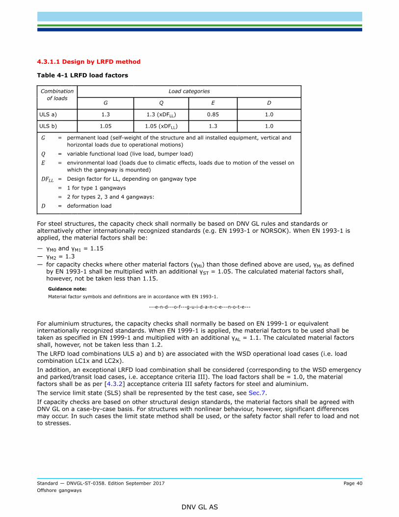
• Sec.4 Structural design and strength— Sec.4 [4.1.5.4]: Rule text has been updated.— Sec.4 [4.2.5]: Rule text has been updated.— Sec.4 [4.3.1]: Requirements for composite materials added.— Sec.4 [4.3.1.1]: Clarifications regarding LRFD design methodology have been added.— Sec.4 [4.3.3]: Rule text has been clarified.— Sec.4 [4.3.5]: Section has been updated.— Sec.4 Table 4-4: Editorial changes have been made.— Sec.4 Table 4-5: Editorial changes have been made.
• Sec.5 Functional requirements— Sec.5 [5.2]: New section added.— Sec.5 [5.5]: Walkway design requirements have been updated.— Sec.5 [5.6]: Clarification regarding the design requirement has been added.— Sec.5 [5.7]: Clarification regarding emergency escape has been added.— Sec.5 [5.9]: Text has been re-written.— Sec.5 [5.10]: New section added.
Cha
nges
- c
urre
nt
Standard — DNVGL-ST-0358. Edition September 2017 Page 4Offshore gangways
DNV GL AS
— Sec.5 [5.11]: Operating angle now defined as range.— Sec.5 [5.13]: Rule text has been updated.— Sec.5 [5.14]: Certification requirements have been added.— Sec.5 [5.15.1]: Clarification regarding compliance with a design standard has been added.— Sec.5 [5.15.5]: Testing requirements aligned with class practice.— Sec.5 [5.17]: Text has been clarified.— Sec.5 [5.18]: Text has been re-written.
• Sec.6 Safety and safety equipment— Sec.6 : Section has been re-written.
• Sec. 7 Testing and marking— Section renamed.— Sec.7 [7.1]: New section has been added.— Sec.7 [7.2.1]: Section has been updated to include requirements for gangways part of/ not part of a class
notation— Sec.7 [7.2.4]: Section has been updated to include more detailed testing requirements and simulator
based testing— Sec.7 [7.2.9]: New section has been added
• Appendix A— In-operation follow-up requirements have been updated, clarified and moved to App.B.— Clarifications regarding the information to be stated in the PC issued by the manufacturer have been
included.
• Appendix B— New appendix for periodical survey, tests and repairs,
Editorial correctionsIn addition to the above stated changes, editorial corrections may have been made.
Con
tent
s
Standard — DNVGL-ST-0358. Edition September 2017 Page 5Offshore gangways
Standard — DNVGL-ST-0358. Edition September 2017 Page 6Offshore gangways
DNV GL AS
5.6 Handrails.........................................................................................505.7 Access to gangway and waiting area..............................................515.8 Protecting grid................................................................................515.9 Lighting...........................................................................................515.10 Operator's cabin..........................................................................525.11 Landing area.................................................................................525.12 Operation angle............................................................................ 535.13 Power system............................................................................... 535.14 Electrical installations, equipment and systems............................545.15 Hydraulic systems.........................................................................545.16 Pneumatic systems....................................................................... 565.17 Control and monitoring systems................................................... 565.18 Control and monitoring systems for active motioncompensating gangways.......................................................................57
Section 6 Safety and safety equipment.................................................................606.1 Safety philosophy........................................................................... 606.2 Safety system................................................................................. 616.3 Generic risk contributors................................................................ 646.4 Monitoring.......................................................................................696.5 Alarm system..................................................................................706.6 Handling of deviations and extended risks..................................... 70
Section 7 Testing and marking............................................................................. 717.1 General........................................................................................... 717.2 Functional testing........................................................................... 727.3 Load testing....................................................................................767.4 Examination after testing............................................................... 787.5 Marking...........................................................................................78
Appendix A Examples on basis for acceptance of product certificates issued bythe manufacturer..................................................................................................82
A.1 Sheaves.......................................................................................... 82A.2 Transmission gears and slewing gears........................................... 82
Appendix B Periodic survey, tests and repairs......................................................84
Con
tent
s
Standard — DNVGL-ST-0358. Edition September 2017 Page 7Offshore gangways
DNV GL AS
B.1 General........................................................................................... 84B.2 Survey, tests and repairs................................................................84B.3 Annual survey............................................................................... 84B.4 5-yearly survey............................................................................. 85B.5 Repairs and modifications of gangways........................................ 86
Standard — DNVGL-ST-0358. Edition September 2017 Page 8Offshore gangways
DNV GL AS
SECTION 1 GENERAL
1.1 IntroductionHowever, the provisions in this standard should represent the technical conclusion resulted following theselection of the appropriate gangway system.DNV GL has developed a walk to work (W2W) guidance, Gangway access to offshore facilities available onDNV GL website and free to download at www.dnvgl.com/w2w, to assist offshore facility operators achievesafe and efficient personnel transfers to/from their facilities via a gangway system on a workboat, ship orsemi-submersible unit.Prior to the proposal of a gangway design, it is recommended that the above mentioned document is used asa reference in better understanding the role of the gangway as an individual piece of equipment in the biggerpicture of manning an offshore facility.
1.2 ObjectiveThis standard provides technical and safety guidance for the design and certification of offshore gangwayswith the purpose of aiding in the development of an alternative solution for manning an offshore facility.
1.3 ScopeThis offshore standard provides criteria and guidance for certification and verification of the design,materials, fabrication, installation, testing and follow-up of gangways used offshore.
1.3.1 GeneralThis standard describes the procedures and requirements for obtaining certificates for offshore gangways.The following topics are covered:
Requirements for operational procedures and training as required for type 3 gangways (see Sec.8), are notpart of the scope.The standard does not cover the gangway's interfaces with the vessel, i.e. welded structural connections andfoundations, electrical/hydraulic power supply, integration with vessel systems or the influence the gangwaymight have on the supporting vessel stability, trim, etc. See relevant rules, DNVGL-CG-0156 and DNVGL-ST-E272 for further information.
1.3.2 Passive and active systemsThe scope of this standard covers both passively and actively motion compensated gangways.
— The design of passive motion compensated gangways incorporates features that allow the gangwayto accommodate the relative motions between vessels without making use of any external systems orequipment.
— Active motion compensation implies a system powered by an external power supply that reduces orcancels (compensates) the effect of the vessel motions (from one degree of freedom to all 6 degrees offreedom) on the gangway structure.
Standard — DNVGL-ST-0358. Edition September 2017 Page 9Offshore gangways
DNV GL AS
1.3.3 Types of gangwaysThe standard covers the following types as related to the operation of the gangway. The appropriate typeshall be agreed with DNV GL prior to commencing design.
1.3.3.1 Type 1Uncontrolled flow of people, routine personnel transfer.
— people move freely between the connected units— connection time: indefinite— gangway is usually supported in X, Y and Z axis directions at both ends— gangway shall not be permanently connected to at least one of the units— gangway shall contain means to self-detach at one end and move away in a safe manner and short time.
1.3.3.2 Type 2Controlled flow of people, routine personnel transfer.
— People do not move freely between the connected units, the flow of people is controlled/regulated bymeans of manual (i.e. the gangway operator) or automatic control.
— Connection time: usually less than 24 hours, the control of the flow of people shall be ensured throughoutthe entire connection time.
— At least one end of the gangway is supported in the X, Y and Z axis directions.— The gangway shall contain means to self-detach at one end and move away in a safe manner and short
time.Guidance note:Connection time may be longer if it is documented that the controlled flow of people is ensured for the entire duration in which thetwo units are connected.
---e-n-d---o-f---g-u-i-d-a-n-c-e---n-o-t-e---
1.3.3.3 Type 3Controlled flow of people, engineered personnel transfer.
— gangways of more simplistic design to be used only in marine operation type personnel transfers.Guidance note:For definitions of routine personnel transfer and engineered personnel transfer see [1.7.2].
---e-n-d---o-f---g-u-i-d-a-n-c-e---n-o-t-e---
1.3.3.4 Type 4Gangways that do not fall into any of the types defined above.
— typically, but not limited to, gangways of more simplistic design, connecting two fixed installations for areduced period of time, that do not contain means to self-detach
— the applicable design requirements shall be agreed on a case-by-case basis with DNV GL.
1.4 Application
1.4.1 This standard is applicable for certification of offshore gangways for vessels with class notation Walk2workor Offshore service vessel (Windfarm maintenance). This standard may also be applied on a voluntarybasis for verification or certification of offshore gangways temporary/permanently installed on a supportingvessel and intended to be used offshore.
Standard — DNVGL-ST-0358. Edition September 2017 Page 10Offshore gangways
DNV GL AS
Offshore gangways outside class scope may be included in DNVGL's modular class scheme to monitor, surveyand document quality of portable offshore gangway system in operations.
Guidance note:The scheme ensures traceability of portable equipment maintaining 5 yearly class survey cycles based on inspection items listed inthis standard.
---e-n-d---o-f---g-u-i-d-a-n-c-e---n-o-t-e---
The standard does not apply to fixed gangways (bridges) permanently installed between two fixedinstallations, nor for vessel-shore gangways.The standard is written for worldwide application. National and governmental regulations may includerequirements in excess of the provisions given by this standard.
1.4.2 This standard applies to gangways used for shore connections connecting two assets which may be:
— floating— fixed.
1.4.3 Cargo transferThe provisions in this standard shall be applied to cargo transfers performed only by means of cargo trolleysover the gangway bridge and service/fluid transfers performed through cables and pipes/hoses fitted withbreak-away or automatic disconnection devices. The specifics of such systems shall be evaluated on a case-by-case basis.Cargo transfers performed by motorized vehicles (e.g. fork lift trucks, etc.) and service/fluid transfersperformed through permanently connected cables and pipes/hoses are not covered in this standard.
1.5 StructureThis document is structured as follows:
— Sec.2 provides information regarding documentation and certification requirements.— Sec.3 to Sec.6 define the technical requirements offshore gangways.— Sec.7 addresses the testing and marking requirements.— Sec.8 defines the specific technical requirements for type 3 gangways.— App.A provides guidance regarding the information to be included in the product certificates issued by the
manufacturer for various gangway components.— App.B covers recommendations for periodic examinations, tests and repairs.
1.6 ReferencesOnly the latest revision of the following referenced standards at the time this document is applied shall beused.
Table 1-1 Rules and standards for certification
Document code Title
DNVGL-RU-HSLC DNV GL rules for classification: High speed and light craft
DNVGL-RU-OU DNV GL rules for classification: Offshore units
DNVGL-RU-SHIP DNV GL rules for classification: Ships
Standard — DNVGL-ST-0358. Edition September 2017 Page 11Offshore gangways
DNV GL AS
Document code Title
DNVGL-ST-0378 Standard for offshore and platform lifting appliances
DNVGL-ST-E272 Offshore service modules
DNVGL-ST-E273 2.7-3 portable offshore units
DNVGL-ST-N001 Marine Operations and marine warranty
Table 1-2 Offshore standards
Document code Title
DNVGL-OS-A101 Safety principles and arrangements
DNVGL-OS-A201 Winterization for cold climate operations
DNVGL-OS-B101 Metallic materials
DNVGL-OS-C101 Design of offshore steel structures, general LRFD method
DNVGL-OS-C401 Fabrication and testing of offshore structures
Table 1-3 Class programmes
Document code Title
DNVGL-CG-0129 Fatigue assessment of ship structures
DNVGL-CG-0156 Conversion of ships
DNVGL-CG-0194 Hydraulic cylinders
Table 1-4 Recommended practices
Document code Title
DNVGL-RP-C203 Fatigue design of offshore steel structures
DNVGL-RP-N101 Risk management in marine - and subsea operations
DNV-RP-C205 Environmental Conditions and Environmental Loads
DNV-RP-D102 Failure Mode and Effect Analysis (FMEA) of Redundant Systems
Table 1-5 Other normative references
Document code Title
EN 13001-3-1 Cranes general design
EN 1993-1 Design of steel structures (eurocode 3)
EN 1999-1 Design of aluminium structures (eurocode 9)
EN 1993-6 Crane supporting structures
MODU code IMO Code for the Construction and Equipment of Mobile Offshore Drilling Units
Standard — DNVGL-ST-0358. Edition September 2017 Page 12Offshore gangways
DNV GL AS
1.7 Glossary
1.7.1 AbbreviationsTable 1-6 Abbreviations
Term Description
AMC active motion compensation
CoG center of gravity
DF dynamic factor
DFF design fatigue factor
DP dynamic positioning
FAT factory acceptance test
FMEA failure mode and effect analysis
G gangway self-weight
HAZID hazard identification analysis
HAZOP hazard and operability study
HW hardware
HPU hydraulic power unit
IACS International Association of Classification Societies
I/O input/output
LL live loads
LRFD load and resistance factor design
MBL minimum breaking load
MOA maximum operational accelerations
MOU mobile offshore units
MPI visual and magnetic particle
MPS manual protection system
MRU motion reference unit
MTA maximum transit/parked accelerations
NDT non-destructive testing
PC product certificate
SAT sea acceptance test
SLS service limit state
SW software
Standard — DNVGL-ST-0358. Edition September 2017 Page 13Offshore gangways
DNV GL AS
Term Description
TA type approval
TD design temperature
ULS ultimate limit state
VIV vortex induced vibrations
W2W walk to work
WSD work stress design
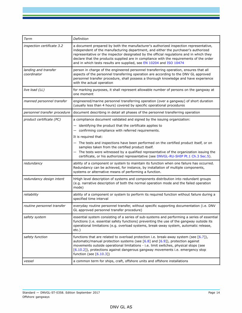
1.7.2 DefinitionsTable 1-7 Definition of terms
Term Definition
clear width width of gangway from toe-board to toe-board or hand rail to hand rail, whichever is thesmallest
If the width varies along the length of the gangway, the smallest width shall represent theclear width.
DNV GL certificate (VL) a product or material certificate validated and signed by a surveyor from DNV GL will bedenoted a VL certificate (see DNVGL-RU-SHIP Pt.1 Ch.3 Sec.5)
short term operation (less than 4 hours, time frame in which the environmentalparameters can be considered stationary) under continuous monitoring of a landing andtransfer coordinator
essential control andmonitoring system
a system that needs to be in continuous operation for maintaining the gangway'sfunctionality
essential service and safetyfunction
a function that must be continuously available
fail-operational a system that continues to operate (e.g. to actively motion compensate) in case of asingle failure in the control system
fail-passive a system that loses partly or completely its functionality (e.g. to actively motioncompensate) in case of control system single failure
The system can still be manually controlled.
gangway (assembly) System intended to transfer personnel and cargo between 2 offshore vessels, typicallyincluding a bridge and a pedestal.
gangway axis — X axis: principal axis oriented along the length of the gangway.— Y axis: secondary axis, perpendicular to X axis, oriented across the length of the
gangway and in the floor/walkway plane.— Z axis: secondary axis, perpendicular to the plane defined by X and Y axis.
inspection certificate 3.1 a document issued by the manufacturer which contains the results of all the required tests
It shall certify that the tests have been carried out by the manufacturer on samples takenfrom the delivered products direct, see EN 10204 and ISO 10474.
Standard — DNVGL-ST-0358. Edition September 2017 Page 14Offshore gangways
DNV GL AS
Term Definition
inspection certificate 3.2 a document prepared by both the manufacturer's authorized inspection representative,independent of the manufacturing department, and either the purchaser's authorizedrepresentative or the inspector designated by the official regulations and in which theydeclare that the products supplied are in compliance with the requirements of the orderand in which tests results are supplied, see EN 10204 and ISO 10474
landing and transfercoordinator
person in charge of the engineered personnel transferring operation, ensures that allaspects of the personnel transferring operation are according to the DNV GL approvedpersonnel transfer procedure, shall possess a thorough knowledge and have experiencewith the actual operation
live load (LL) for marking purposes, it shall represent allowable number of persons on the gangway atone moment
manned personnel transfer engineered/marine personnel transferring operation (over a gangway) of short duration(usually less than 4 hours) covered by specific operational procedures
personnel transfer procedure document describing in detail all phases of the personnel transferring operation
product certificate (PC) a compliance document validated and signed by the issuing organization:
— identifying the product that the certificate applies to— confirming compliance with referred requirements.
It is required that:
— The tests and inspections have been performed on the certified product itself, or onsamples taken from the certified product itself.
— The tests were witnessed by a qualified representative of the organization issuing thecertificate, or his authorized representative (see DNVGL-RU-SHIP Pt.1 Ch.3 Sec.5).
redundancy ability of a component or system to maintain its function when one failure has occurred.Redundancy can be achieved, for instance, by installation of multiple components,systems or alternative means of performing a function.
redundancy design intent hHigh level description of systems and components distribution into redundant groups(e.g. narrative description of both the normal operation mode and the failed operationmode)
reliability ability of a component or system to perform its required function without failure during aspecified time interval
routine personnel transfer everyday routine personnel transfer, without specific supporting documentation (i.e. DNVGL approved personnel transfer procedure)
safety system essential system consisting of a series of sub-systems and performing a series of essentialfunctions (i.e. essential safety functions) preventing the use of the gangway outside itsoperational limitations (e.g. overload systems, break-away system, automatic release,etc.)
safety function functions that are related to overload protection i.e. break-away system (see [6.7]),automatic/manual protection systems (see [6.8] and [6.9]), protection againstmovements outside operational limitations - i.e. limit switches, physical stops (see[6.10.2]), protections against dangerous gangway movements i.e. emergency stopfunction (see [6.10.3])
vessel a common term for ships, craft, offshore units and offshore installations
Standard — DNVGL-ST-0358. Edition September 2017 Page 15Offshore gangways
DNV GL AS
Term Definition
weight of one fully kittedperson (including luggage/tools)
100 kg, to be used for establishing the live load (LL) of the gangway
worst case failure designintent
refer to the minimum remaining capacity after any relevant single failure or commoncause (for a given operational mode)
1.7.3 Verbal formsTable 1-8 Definition of verbal forms
Term Definition
may verbal form used to indicate a course of action permissible within the limits of the document
shall verbal form used to indicate requirements strictly to be followed in order to conform to the document
should verbal form used to indicate that among several possibilities one is recommended as particularly suitable,without mentioning or excluding others, or that a certain course of action is preferred but not necessarilyrequired
Standard — DNVGL-ST-0358. Edition September 2017 Page 16Offshore gangways
DNV GL AS
SECTION 2 DOCUMENTATION AND CERTIFICATION
2.1 Documentation
2.1.1 OverviewDocumentation shall be submitted as required by Table 2-1.
Table 2-1 Documentation requirements
Object Documentationtype
Additional description info
C010 - designcriteria
Operational limitations (principal loads, environmental loads, vesselmotions, etc), gangway type
FI
C020 - assemblyor arrangementdrawing
A drawing showing how the parts of a mechanical assembly arearranged together (general arrangement)
FI
C030 - detaileddrawing
Gangway structure and components for slewing, luffing and telescoping(including drives)
Winches with gears and brakes (when in use during personnel transfers)
AP
C040 - designanalysis
See [2.1.2] FI
C050 - non-destructivetesting (NDT)plan
A document describing the methods, extent and criteria for the non-destructive testing that shall be performed
AP
Z051 - designbasis
A document describing:
— regulatory basis for the design, i.e. applicable rules, regulations andstandards
— all functions incorporated in the system and their technicalrealization
— all interfaces towards other systems, including their technicalrealization
FI
Safety G170 - Safetyphilosophy
A document that shall be submitted in the initial design phase, providinginformation as per [6.1]
FI
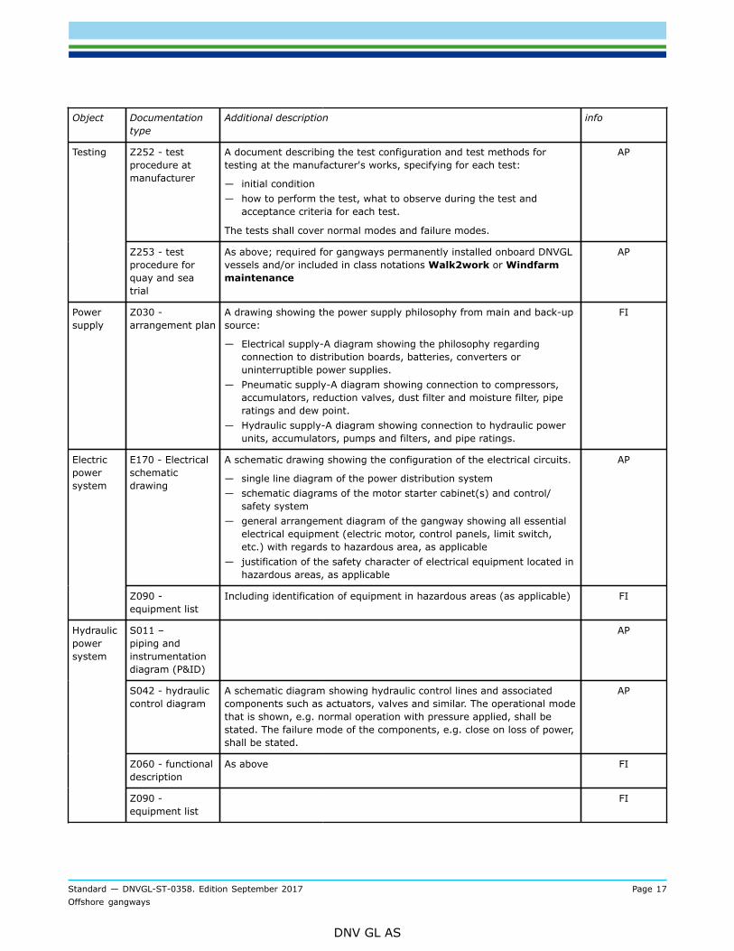
Standard — DNVGL-ST-0358. Edition September 2017 Page 17Offshore gangways
DNV GL AS
Object Documentationtype
Additional description info
Z252 - testprocedure atmanufacturer
A document describing the test configuration and test methods fortesting at the manufacturer's works, specifying for each test:
— initial condition— how to perform the test, what to observe during the test and
acceptance criteria for each test.
The tests shall cover normal modes and failure modes.
APTesting
Z253 - testprocedure forquay and seatrial
As above; required for gangways permanently installed onboard DNVGLvessels and/or included in class notations Walk2work or Windfarmmaintenance
AP
Powersupply
Z030 -arrangement plan
A drawing showing the power supply philosophy from main and back-upsource:
— Electrical supply-A diagram showing the philosophy regardingconnection to distribution boards, batteries, converters oruninterruptible power supplies.
— Pneumatic supply-A diagram showing connection to compressors,accumulators, reduction valves, dust filter and moisture filter, piperatings and dew point.
— Hydraulic supply-A diagram showing connection to hydraulic powerunits, accumulators, pumps and filters, and pipe ratings.
FI
E170 - Electricalschematicdrawing
A schematic drawing showing the configuration of the electrical circuits.
— single line diagram of the power distribution system— schematic diagrams of the motor starter cabinet(s) and control/
safety system— general arrangement diagram of the gangway showing all essential
electrical equipment (electric motor, control panels, limit switch,etc.) with regards to hazardous area, as applicable
— justification of the safety character of electrical equipment located inhazardous areas, as applicable
APElectricpowersystem
Z090 -equipment list
Including identification of equipment in hazardous areas (as applicable) FI
S011 –piping andinstrumentationdiagram (P&ID)
AP
S042 - hydrauliccontrol diagram
A schematic diagram showing hydraulic control lines and associatedcomponents such as actuators, valves and similar. The operational modethat is shown, e.g. normal operation with pressure applied, shall bestated. The failure mode of the components, e.g. close on loss of power,shall be stated.
AP
Z060 - functionaldescription
As above FI
Hydraulicpowersystem
Z090 -equipment list
FI
Standard — DNVGL-ST-0358. Edition September 2017 Page 18Offshore gangways
DNV GL AS
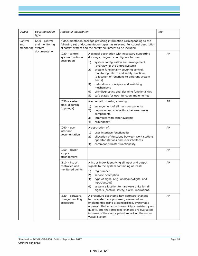
Object Documentationtype
Additional description info
A documentation package providing information corresponding to thefollowing set of documentation types, as relevant. Functional descriptionof safety system and the safety equipment to be included.
I020 - controlsystem functionaldescription
A textual description with necessary supportingdrawings, diagrams and figures to cover:
1) system configuration and arrangement(overview of the entire system)
2) system functionality covering control,monitoring, alarm and safety functions(allocation of functions to different systemitems)
3) redundancy principles and switchingmechanisms
4) self-diagnostics and alarming functionalities5) safe states for each function implemented.
AP
I030 – systemblock diagram(topology)
A schematic drawing showing:
1) arrangement of all main components2) networks and connections between main
components3) interfaces with other systems4) redundancy.
AP
I040 – userinterfacedocumentation
A description of:
1) user interface functionality2) allocation of functions between work stations,
operator stations and user interfaces3) command transfer functionality.
AP
I050 - powersupplyarrangement
AP
I110 – list ofcontrolled andmonitored points
A list or index identifying all input and outputsignals to the system containing at least:
1) tag number2) service description3) type of signal (e.g. analogue/digital and
input/output)4) system allocation to hardware units for all
signals (control, safety, alarm, indication).
AP
Controlandmonitoring
I200 - controland monitoringsystemdocumentation
I320 – softwarechange handlingprocedure
A procedure describing how software changesto the system are proposed, evaluated andimplemented using a standardized, systematicapproach that ensures traceability, consistency andquality, and that proposed changes are evaluatedin terms of their anticipated impact on the entirevessel system.
AP
Standard — DNVGL-ST-0358. Edition September 2017 Page 19Offshore gangways
DNV GL AS
Object Documentationtype
Additional description info
Z252 – testprocedure atmanufacturer
A document describing the test configuration andtest methods for testing at the manufacturer'sworks, specifying for each test:
1) initial condition2) how to perform the test3) what to observe during the test and
acceptance criteria for each test.
The tests shall cover normal modes and failuremodes.
AP
I140 –softwarequality plan
Document to be sent to the approval centre and describing the softwarelife cycle activities. This document shall, as a minimum, contain thedescription of the procedures for:
1) software and hardware requirements specification2) software and hardware design and development plans3) software verification plans4) software module testing5) software integration testing6) software validation, both functionality and failure modes.
Items 3-6 may also be handled during manufacturing survey. They maybe part of a simulator based testing scope, see [7.2.4.2].
FI
Z070 - failuremode description
Required for passive compensated gangways.
A document describing the effects due to failures in the systems, notfailures in the equipment supported by the systems. The followingaspects shall be covered:
— list of failures which are subject to assessment, with references tothe system documentation
— description of the system response to each of the above failures,including a list of gangway safe positions
— comments to the consequence of each of these failures.
FI
Z071 - failuremode and effectanalysis (FMEA)
Required for active motion compensated gangways.
A document where the system response to possible failures areidentified and analysed.
The FMEA applies for the gangway redundant systems. See DNV-RP-D102 Failure mode and effect analysis (FMEA) of redundant systems forrecommended practice when providing objective evidence of requiredredundancy and fault tolerance, see also [5.18.2.2].
FI
Z161 - operationmanual
See [2.1.3] FI
I110 - List ofcontrolled andmonitored points(I/O list)
As above. FI
Simulatortestpackage
Test setupblock diagram(topology)
A drawing showing PLCs, HMIs, network switches, simulators,communication lines and interfaces, including hardware serial numbers.
FI
Standard — DNVGL-ST-0358. Edition September 2017 Page 20Offshore gangways
DNV GL AS
Object Documentationtype
Additional description info
Simulator usermanual
A document describing the simulator architecture, the simulatorfunctionality (how to introduce failures, how to trend signals etc.) andthe different graphical user interfaces (GUI).
FI
Test setupvalidation testprogram
A document listing the validation tests to be performed, proving thatthe simulator functionality is adequate for the testing scope, i.e. all themodes and functions shall be included.
AP
Simulator testprogram
A document based on the functional description and FMEA/failure modedescription listing functions and failure modes to be tested specifying foreach test:
— test case reference/ID number— initial condition— how to perform the test, what to observe during the test and
acceptance criteria for each test.
AP
Simulator testreport
A document including recorded results for each of the test cases asincluded in the simulator test program.
Findings identified shall be described in the report including at least thefollowing information:
— test case reference/ID number— description of the finding, including an explanation of why it is a
finding— recommended action or follow-up— responsible party for following-up corrective action— deadline for completion of the action.
The document shall also include details / information about the systemand simulator setup for the simulator testing, such as:
— software version numbers for system under test— software version numbers for simulator used for testing.
The documentation related to equipment protection shall be basedon the assessment of the risk contributors as described in [6.3.14]. Adocument describing the fire safety system and the safety equipment,including:
— fire area identification and location— area classification— type of ventilation— expected personnel occupancy— area enclosure and fire rating— hazards— types and locations of fire detectors— types and locations of gas detectors— active fire protection— a matrix relating typical input signals from detectors, release points,
etc. to typical output actions— arrangement drawing showing the primary and secondary escape
routes from the gangway and information regarding escape routesand their directions, safe areas, muster stations.
AP
Standard — DNVGL-ST-0358. Edition September 2017 Page 21Offshore gangways
DNV GL AS
Object Documentationtype
Additional description info
FI = for information
AP = approved
For general requirements for documentation, including definition of the info codes, see DNVGL-RU-SHIP-Pt.1Ch.3 Sec.2 and DNVGL-RU-SHIP-Pt.1 Ch.3 Sec.3.
2.1.2 Design analysisFor structural parts and components above, the drawings shall be supplemented with calculationsdemonstrating that the structural strength complies with the requirements. The documentation shall containinformation regarding objectives, premises, assumptions and conclusions. A complete listing of structuralcomponents and parts subjected to strength calculations shall be submitted. The list shall include informationof:
— types of failures considered (excessive yielding, buckling, fatigue fracture)— elastic or plastic analysis performed— permissible stress (WSD) or limit state method (LRFD) used.
See Sec.4.
2.1.3 Operation manualA manual shall be prepared, containing information regarding operation modes, operating instructionsfor normal and degraded operating modes, operational limitations, user interface description, transfer ofcontrol, redundancy, failure detection and identification facilities (automatic, manual), data security, accessrestrictions, special areas requiring user attention, procedures for start-up, restoration of functions, close-down (e.g. retrieval, parking, etc.). A few guidelines are provided below:
— The operational limitations, such as maximum number of persons on gangway (live load (LL)), the actualdistribution of the LL along the gangway, operational length range, wind speed, operational luffing anglerange, vessel accelerations, etc.
— Normal use of the gangway with information about:
— deployment/retrieval procedures— operational procedure (preparations prior to personnel transfers, control of flow of people, etc.).
— Emergency procedures with information about:
— fixed procedures as to when the gangway connection shall be interrupted and when it can be re-established (hazard identification)
— differentiation/definition of manual vs automatic disconnection situations.
— Continuous maintenance and repair routines to ensure that the gangway and all the appurtenant systemsfunction properly at all times.
Guidance note:Further guidance on the information to be included in the gangway manual may be found in EN 13852-1 Sec.7.
---e-n-d---o-f---g-u-i-d-a-n-c-e---n-o-t-e---
Standard — DNVGL-ST-0358. Edition September 2017 Page 22Offshore gangways
DNV GL AS
2.2 Certification
2.2.1 GeneralTable 2-2 lists the certificate requirements for offshore gangways.
Table 2-2 Certificate requirements for offshore gangways
Object Certificate type Issued by Certification standard Additional description
Slewing rings PC DNVGL DNVG-ST-0378
Hydraulic cylinders
Accumulators
PC DNVGL DNVGL-CG-0194
Winches PC DNVGL DNVGL-ST-0378 For luffing and telescoping winches.
Sheaves PC DNVGL/Manufacturer
DNVG-ST-0378 Product certificate (PC) or workcertificate (W) issued by manufacturercertificate will be satisfactory for un-welded sheaves. For examples ofinformation typically included in workcertificates, see App.A.
Wire ropes CG4 DNVGL DNVG-ST-0378 Certificate of test and thoroughexamination of wire rope.
Alternatively ILO form No.4 issued byother competent person according to IL152.
Transmission gearsand brakes
PC DNVGL/Manufacturer
DNVG-ST-0378 Applicable when transmitting brakingforces for luffing and telescoping, see[4.3.5.5].
W issued by manufacturer may beaccepted provided that the winch is notcategorized as for lifting of personnel.
W issued by the manufacturer shallstate compliance of the design with theapproved drawings (see above C030).The information to be included in thePC shall be based on App.A.
Slewing gear PC Manufacturer DNVG-ST-0378 Also other transmission gears for non-critical applications, see [4.3.5.7].
W issued by the manufacturer shallstate compliance of the design withthe approved drawings (see aboveTable 2-1 C030). The information to beincluded in the PC shall be based onApp.A.
Hydrauliccomponents
TR Manufacturer N/A
Standard — DNVGL-ST-0358. Edition September 2017 Page 23Offshore gangways
DNV GL AS
Object Certificate type Issued by Certification standard Additional description
Control system PC + TA DNVGL DNVG-ST-0358 Product certificate, valid type approval(TA) issued by DNV GL.The gangway control systemcomprising of electrical, hydraulic,pneumatic, control and monitoring andsafety systems.
PC = Product Certificate, MC = Material Certificate, TR = Test Report
For definition of certificate types, see DNVGL-RU-SHIP Pt.1 Ch.3 Sec.5.
2.2.2 Certification procedure2.2.2.1 GeneralThe following activities are covered by this standard:
— design examination— survey during fabrication and installation— witness testing and marking.
2.2.2.2 Design examinationLoad-carrying and other important components of a gangway are subject to design review with respectto strength and suitability for its purpose. A design approval is granted when the design review has beenconcluded without detection of non-compliance towards this standard.Strength review of components related to power supply and safety equipment is not part of the scope of thisdocument.Each gangway is normally given a separate design approval.The design approval may be obtained either on a case-by-case basis or as a general type approval..The type approval means that the design as approved can be applied for identical units to be fabricated, i.e.requested documents need not be submitted for each unit. The type approval is based on certain conditionsand its period of validity may be limited. See DNVGL-CP-0338 Type approval scheme.
2.2.2.3 Survey during fabricationA survey during manufacture of each separate gangway shall be carried out by DNV GL's surveyor in order toascertain compliance with the approved drawings, other requirements of this certification standard, as well asgeneral good workmanship.As an alternative to survey during manufacture of each separate gangway, modified survey procedures andsurvey arrangements may be accepted, see DNVGL-CP-0337.
2.2.2.4 Testing and markingTesting and marking shall be performed as per Sec.7 requirements.
2.2.2.5 Extension of scope of workUpon request from the customer, the scope of work may be extended beyond the subjects and aspectscovered in this certification standard. Extensions shall be agreed in writing. DNV GL may, if found necessary,require that the customer presents reference documents for the extended scope of work, such as authorityregulations, norms and standards.In case of disputes regarding interpretations of requirements on which extended work is based, thecustomer shall contact the publisher/owner of the requirements and obtain their written interpretation. If thepublisher/owner is not willing to interpret the disputed requirement, or an interpretation for other reasonscannot be acquired, the DNV GL interpretation will prevail.
Standard — DNVGL-ST-0358. Edition September 2017 Page 24Offshore gangways
DNV GL AS
2.2.2.6 Limitation of scope of workUpon request from and agreed with the customer, parts of the scope of work, components, systems orspecific aspects or requirements may be excluded from the scope of work specified in this certificationstandard. This will be annotated in the documentary evidence of the completed assignment (certificate).DNV GL will not agree to limit the scope of work or parts of the suggested services if they are of the opinionthat this may lead to hazards or unacceptable lowering of the safety standard.A limitation of scope of work is not applicable when a DNV GL product certificate is required.
2.2.3 CertificateAs a minimum the certificate shall contain:
— reference to a signed factory acceptance tests report— design parameters/limitations given in approval letter or type approval certificate— list of certified sub-components (see Table 2-2, as applicable)— reference to valid type approval certificates/approval letters for the certified sub-components— list of tests to be carried out after installation on-board (as applicable, see [7.2.1].
DNV GL’s formal documentation of the certification to the customer will be the product certificate issued uponcompletion of the project.
Standard — DNVGL-ST-0358. Edition September 2017 Page 25Offshore gangways
DNV GL AS
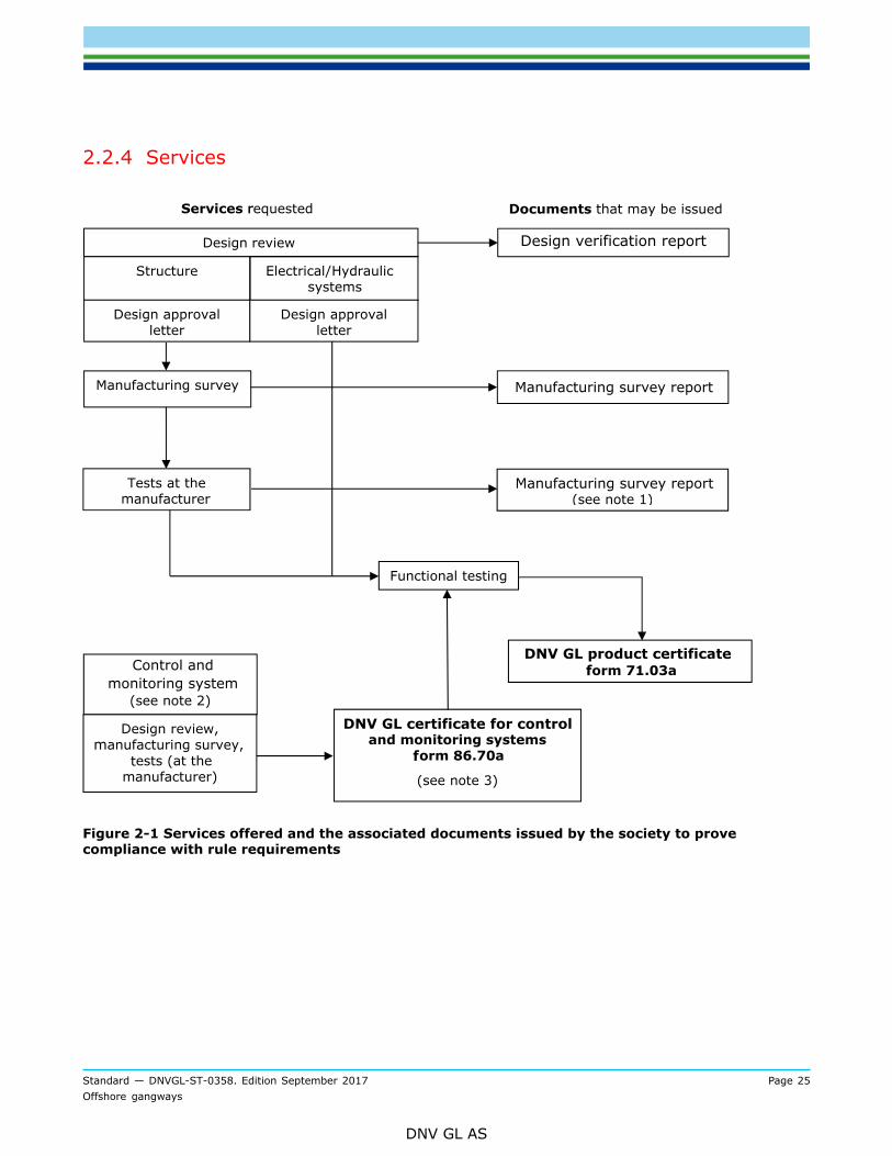
2.2.4 Services
Figure 2-1 Services offered and the associated documents issued by the society to provecompliance with rule requirements
Standard — DNVGL-ST-0358. Edition September 2017 Page 26Offshore gangways
DNV GL AS
Note:
1) The manufacturing survey report shall clearly state that only the gangway assembly structural part is covered. The DNV GLproduct certificate for the gangway shall be issued following the certification of the control and monitoring system and successfulfunctional test of the fully assembled gangway (structure and control system).
2) Control and monitoring system is typically part of the same scope/delivery as the electrical and hydraulic system. If deliveredby a 3rd party, the separate branch of the figure may be applied
3) The DNV GL certificate for control and monitoring systems may be combined with the DNV GL product certificate for the gangwayassembly into one certificate.
---e-n-d---o-f---n-o-t-e---
2.3 Periodic inspection
2.3.1 GeneralIt is recommended to have a regular inspection during operational use according to an established plan,either from manufacturer and/or as defined by regulatory bodies.Periodic inspection may be required to be carried out by DNV GL as part of classification’s scope annualsurvey. As an alternative, other inspection bodies or the original manufacturer/authorized representative(recognised by flag/state authorities) may carry out such inspections.Notwithstanding the above, major repairs or modifications which may alter the certificate shall be approvedby DNV GL.
2.3.2 Gangways included in class scopeOffshore gangways included in the class scope shall be subject to a periodical inspection regime as perrequirements in App.B. The periodic inspections shall be carried out by DNV GL as part of classification'sscope annual/every five years survey.
Standard — DNVGL-ST-0358. Edition September 2017 Page 27Offshore gangways
DNV GL AS
SECTION 3 MATERIALS AND FABRICATION
3.1 GeneralThis section describes the structural categorization, selection of materials and inspection principles to beapplied in design and construction of offshore gangways.The below requirements for materials for structural members and equipment are applicable for gangwayswith design temperature TD down to -30°C. Materials for gangways with design temperature below -30°Cmay be specially considered.Materials with properties deviating from the requirements in this section may be accepted upon specialconsideration.As an alternative, materials that comply with national or proprietary specifications may be accepted providedsuch specifications are considered by DNVGL to be equivalent to the requirements in DNVGL-OS-B101 or areespecially approved.
3.2 Design temperatureDesign temperature is a reference temperature used as a criterion for the selection of material grades.The design temperature TD for offshore gangways is defined as the lowest acceptable service temperature.For gangways installed on vessels or mobile offshore units classified by DNV GL, the design temperatures ofthe gangway and the supporting vessel/unit are recommended to be compatible.If not otherwise specified, the design temperature shall be -20°C.
3.3 Structural categoryThe following categorization will be used for structural members:
— Special: highly stressed areas where no redundancy for total collapse exists.— Primary: structures carrying main load as well as components with highly stressed areas.— Secondary: structures other than primary and special members.
Slewing bearings with flanges shall normally be categorized as special, other structure, including thepedestal, transmitting principle loads are normally categorized as primary.The categories shall be agreed with DNV GL in each case.Bolted connections shall be categorized according to DNVGL-ST-0378 [3.4.4.1].
Guidance note:Highly stressed areas are considered to be areas utilized more than 85% of the allowable yield capacity.
---e-n-d---o-f---g-u-i-d-a-n-c-e---n-o-t-e---
3.4 Material manufacture survey, certification and testingproceduresCertificates covering specification of the chemical composition and mechanical properties shall be presentedfor all materials for all load-carrying structures and mechanical components. The test values shall showconformity with the approved specification. Test specimens shall be taken from the products delivered.For testing/retesting procedures and requirements, see DNVGL-OS-B101, as applicable.DNV GL approved material manufacturer will not be required.Material certificate type 3.1 shall be provided for all materials used for special and primary structures.Slewing rings with bolts, nuts, washers, etc. shall be provided with material certificates type 3.2.
Standard — DNVGL-ST-0358. Edition September 2017 Page 28Offshore gangways
DNV GL AS
Guidance note:The document designation inspection certificate type 3.1, 3.2 and 2.1 are in accordance with ISO 10474.
---e-n-d---o-f---g-u-i-d-a-n-c-e---n-o-t-e---
Materials shall be adequately marked for identification. The marking shall at least comprise name or trademark of the manufacturer, material grade, heat number and when referred to 3.2 certificates, the stamp ofthe purchaser's authorized representative.Marking and identification of smaller items, e.g. bolts and nuts, shall be especially agreed upon betweenmanufacturer and DNV GL, but shall at least comply with fastener product standard.Materials without proper identification shall be rejected unless renewed testing verifies compliance withapproved specifications. The number and type of tests will be decided in each case.
3.5 Structural materials
3.5.1 Rolled structural steel for welding3.5.1.1 GeneralCertificates covering specification of the chemical composition and mechanical properties shall be presentedfor all materials for all load-carrying structures and mechanical components.The requirements to chemical composition, mechanical properties, etc. are given in DNVGL-OS-B101.As an alternative, materials that comply with national or proprietary specifications may be accepted providedsuch specifications show reasonable equivalence to the requirements in DNVGL-OS-B101 or are case-by-caseapproved.The grade of steel to be used shall in general be related to the service temperature and thickness for theapplicable structural category, see DNVGL-OS-C101 Table 3-5.
3.5.1.2 Impact testRequired impact test temperatures are dependent on TD and the material thickness. Impact testtemperatures are given in Table 3-1 for structural steel for special, primary and secondary applications.For structural members subjected to compressive and/or low tensile stresses, modified requirements may beconsidered, i.e. greater material thicknesses for the test temperatures specified.Impact test temperature for flanges for slewing bearings shall be as for primary members given in Table 3-1 based on actual thickness.When welding a thinner plate to a thicker plate, e.g. connecting a flange to the supporting structure for theflange, inserted reinforcement rings etc., the following shall apply, provided that the thicker plate does notcontain butt welds. The impact test temperature shall be the lower of the temperatures according to Table3-1, based on t1 or 0.25 x t2 where: t1 = thickness of the thinner supporting platet2 = thickness of the flange. However, the impact test temperature for the flange (thicker plate) shall not be higher than the required testtemperature, based on t2 according to Table 3-1, plus 30°C.
Standard — DNVGL-ST-0358. Edition September 2017 Page 29Offshore gangways
DNV GL AS
Table 3-1 Impact test temperatures for welded structural steel
Impact test temperature in °C1)Material thickness t in mm
Structural steel for specialand primary members2)
Structural steel forsecondary members2)
6 ≤ t ≤ 123) TD + 10 Test not required
12 < t ≤ 25 TD Test not required
25 < t ≤ 50 TD - 20 TD
t > 50 TD - 40 TD - 10
1) For steel with yield stress below 500 MPa, the test temperature need not be taken lower than -40°C. For steelwith yield stress above 500 MPa, the test temperature shall not be taken higher than 0°C and not lower than-60°C.
2) See [3.3] for categorization.3) For plate thickness less than 6 mm, charpy V testing will not be required.
Acceptance criteria shall be as per DNVGL-OS-B101 Ch.2 Sec.1 [5.3].
3.5.2 Rolled structural steel not for welding3.5.2.1 GeneralRolled steel for special and primary components other than those mentioned in [3.5.2.2] and [3.5.2.3] (e.g.mechanisms) shall be specified with reference to a recognized standard. The material shall be delivered inthe following conditions:
— carbon and carbon/manganese steel in normalized condition— alloy steel in quenched and tempered condition— as rolled condition, when subjected to special consideration.
For all materials, impact toughness shall be documented by charpy V-notch impact tests. Test temperaturesshall be as specified in Table 3-2 but, in the case of low calculated stresses, e.g. not exceeding 50 N/mm2, atest temperature of 20°C will be accepted. Required minimum impact energy value shall be as per DNVGL-OS-B101 Ch.2 Sec.1 [5.3].
Table 3-2 Impact testing for rolled steel not for welding
Material thickness t in mm Impact test temperature in °C
t ≤ 10 Impact test not required
10 < t ≤ 50 TD +20
50 < t ≤ 100 TD +10
t > 100 TD
3.5.2.2 Bolts and nutsMaterials for bolts and nuts shall comply with the requirements in [3.5.4] for bolts and nuts.
3.5.2.3 Rolled ringsRolled rings for important components such as slewing rings, toothed wheel rims etc. shall comply with therequirements for steel forgings, see [3.5.3].
Standard — DNVGL-ST-0358. Edition September 2017 Page 30Offshore gangways
DNV GL AS
3.5.3 Steel forgings3.5.3.1 Steel forgingsSteel forgings shall comply with the requirements in DNVGL-OS-B101.As an alternative, materials that comply with national or proprietary specifications may be accepted providedsuch specifications show reasonable equivalence to the requirements in DNVGL-OS-B101 Ch 2 Sec 3 orare specially approved. As a minimum the following particulars shall be specified: manufacturing process,chemical composition, heat treatment, mechanical properties and non-destructive testing.For machinery components, see DNVGL-RU-SHIP Pt.4 Ch.2 Sec.3.Impact testing requirements shall not be less than those in Table 3-3.
Table 3-3 Impact testing for steel forgings
Design temperature TD Test temperature Minimum charpy value
TD ≥ -20°C 0°C 27 J
-20°C > TD > -30°C -20°C
or
(0°C)
27 J
(48 J)
3.5.3.2 Forged rings for slewing bearingsSpecifications of slewing rings essential for the structural and operational safety of the gangway are subjectto individual approval by DNV GL. All relevant details shall be specified such as chemical composition,mechanical properties, heat treatment, depth and hardness of surface hardened layer and surface finish offillets. Position of test specimens shall be indicated. Method and extent of non-destructive testing shall bespecified and the testing procedures shall be stated. Detailed information about method of manufacture shallbe submitted.For each new material of which the manufacturer has no previous experience and for any change in heattreatment of a material previously used, a principal material examination shall be carried out. This meansthat DNV GL may impose additional requirements not specified in this standard. The results shall besubmitted to DNV GL for consideration. The programme for such examination shall be agreed with DNV GL.All test results shall comply with the approved specifications.Steel for slewing rings shall satisfy the requirements of Table 3-4.
Table 3-4 Slewing ring materials
Heat treatment According to approved specification
Charpy V-notch test temperature TD
Average 42
Charpy V-notch value Single min. value 27
Elongation A5 (minimum) 14%
Fatigue properties Documentation may be required bytype tests on specimen of ring section
Fracture toughness Documentation may be required by typetests on specimen of ring section in question
Standard — DNVGL-ST-0358. Edition September 2017 Page 31Offshore gangways
DNV GL AS
3.5.4 Bolts and nutsBolt connections are normally considered to be in the following groups:
— Special: where bolts or nuts are part of a slewing ring connection.— Primary: where the bolts or nuts are transferring principle loads.— Secondary: where the bolts or nuts are transferring load, not belonging in the category special or primary.
Examples are bolt connections in driver’s cabin, platforms, stairs and ladders.
Bolts and nuts for use in connections categorized as special or primary shall conform with and be tested inaccordance with a recognized standard, e.g. pertinent parts of ISO 898 or other recognized standard.Additional requirements to testing and inspection of slewing ring bolts are given in Table 3-5.
Table 3-5 Testing and inspection of slewing ring bolts
Strengthclass, ISO898, or
equivalent
Diameterd in mm
UltimatestrengthN/mm
YieldstrengthminimumN/mm2)
ElongationA5
Requiredcharpy V
energy1) attest temp. asrequired for
rings Table 3-3
Fracturemechanics
testing(CTOD)
Surface inspection2)
d < 25 - -8.8
d ≥ 25
800 - 1000 640 14
42 J -
d < 25 - -10.93)
d ≥ 25
1000 - 1200 900 12
42 J -
Visual and magneticparticle (MPI)
1) Average value. Single value accepted to be 30% lower.2) For all the bolts (100%), magnetic particle testing shall be carried out at least 48 hours after completion of quenching
and tempering for bolts with yield strength above 355 N/mm2. Inspection shall be in accordance with ASTM E 709.Depth of longitudinal discontinuities shall not exceed 0.03 of the nominal diameter. Transverse cracks will not beacceptable irrespective of crack depth and location. Other surface irregularities will be considered in each case.
3) Bolt material having minimum specified yield strength higher than 1100 N/mm2 will normally not be accepted.
Bolt connections considered as secondary shall be made from suitable materials.Nuts may be accepted to be in one strength class lower than the bolts of bolt/nut assemblies.Bolts and nuts shall be delivered with the following certificates as per EN10204, verifying compliance with thematerial requirements and other test requirements:
— Inspection certificate type 3.2 for slewing ring bolts and nuts.— 2.1 test report for bolts and nuts in primary and secondary connections.
Slewing ring bolts shall have rolled threads, and the rolling shall be performed after final quenching andtempering of the bolts. 12.9 bolts are not accepted as slewing ring bolts.Fasteners (bolts, nuts and washers) in marine environment shall normally be hot-dipped galvanized orsherardised with coating thickness min. 50 micrometre. If special thread profiles or narrow tolerancesprohibit such coating thickness, bolts/nuts may be supplied electro-plated or black provided properly coated/painted after installation. Pickling and electro-plating operations shall be followed by immediate hydrogen-relief (degassing) treatment to eliminate the risk of hydrogen embrittlement.Galvanizing of bolts and nuts are acceptable provided additional loss of bolt load (pretension) of at least 4%is compensated for.
Standard — DNVGL-ST-0358. Edition September 2017 Page 32Offshore gangways
DNV GL AS
3.5.5 Steel castingsSteel castings shall comply with the requirements in DNVGL-OS-B101.
3.5.6 Steel pipes, tubes and fittingsSteel pipes, tubes and fittings shall comply with the requirements in DNVGL-OS-B101.
3.5.7 Aluminium alloysAluminium alloys shall comply with the requirements in DNVGL-OS-B101. The aluminium grade and hardnessshall be selected such that risks of thermite reactions are mitigated, see [6.3.14].
3.5.8 Non-metallic materialsNon-metallic materials shall comply with the requirements in DNVGL-RU-SHIP Pt.2 Ch.3.As an alternative, materials that comply with national or proprietary specifications may be accepted providedsuch specifications are considered by DNVGL to be equivalent to the requirements in DNVGL-RU-SHIP Pt.2Ch.3 or are case-by-case approved by the Society/DNVGL.
3.5.9 Steel wire ropesSteel wire ropes shall comply with the requirements in DNVGL-ST-0378 [3.10].
3.6 Fabrication and testing
3.6.1 GeneralThe manufacturer shall have a system for quality control involving competent personnel with definedresponsibilities that shall cover all aspects of quality control. For qualification of welders, see DNVGL-OS-C401. The materials shall be identifiable during all stages of manufacturing and construction.Manufacturing and construction shall be in accordance with the approved drawings and specifications.The specification shall refer to recognized codes, standards or rules relevant for the structure in question.Supplementary requirements amending the reference documents may be stipulated.Dimensional tolerances specified in the design analysis of the gangway structures shall be complied withduring manufacturing and construction.All defects and deficiencies shall be corrected before the structural parts and equipment are painted, coatedor made inaccessible.Alternative methods of making joints may be considered by DNV GL and will be subject to consideration ineach case.
3.6.2 Forming of materialsForming of materials shall comply with the requirements in DNVGL-OS-C401.
3.6.3 WeldingAll aspects relating to welding (i.e. welding procedures, consumables, welding preparations, weldingperformance, repairs, heat-treatment, production, inspection, NDT and acceptance criteria) shall comply withthe requirements in DNVGL-OS-C401.
Standard — DNVGL-ST-0358. Edition September 2017 Page 33Offshore gangways
DNV GL AS
3.6.4 Non-destructive testing acceptance criteria for components machinedafter forging/castingAcceptance criteria from the following documents can be used for NDT of machined components, unlessotherwise specified in the approved manufacturer's specification.For forged components:
— IACS recommendation no.68, inspection zone 1.
For cast components:
— IACS recommendation no.69, quality level 1.
NDT testing shall be focused on critical areas. Extent to be specified by the manufacturer and shall beaccording to recognized standards.
Guidance note:The objective and scope of quality control for materials, material testing and documentation thereof is to verify that the relevantproperties as specified by the designer and accepted by DNV GL are obtained.
---e-n-d---o-f---g-u-i-d-a-n-c-e---n-o-t-e---
3.6.5 Material protection against corrosion3.6.5.1 SteelSteel surfaces exposed to marine atmospheric conditions shall be protected by a suitable coating system.Steel surfaces to which application of coating is not possible and which are exposed to internal corrosiveconditions shall be protected by other protective systems such as oil, grease, grouting etc.Bolts, nuts and associated elements shall be protected by hot-dip galvanizing according to relevantstandards, e.g. BS 729 or ASTM A 153-82. Alternatively they may be fully encapsulated and the open spacebe filled with inhibited oil, grease etc.Other protection methods may be accepted upon special consideration by DNV GL.
3.6.5.2 AluminiumCorrosion protection for aluminium alloys shall comply with the requirements in DNVGL-RU-HSLC Pt.3 Ch.3Sec.2.Other protection methods may be accepted upon special consideration by DNV GL.
3.6.5.3 Steel and aluminium connectionsIn areas exposed to green sea/sea spray, a non-hygroscopic material shall be applied between steel/stainlesssteel and aluminium in order to prevent galvanic corrosion. Bolts with nuts and washers shall be of stainlesssteel, quality A4-316 or equivalent.Horizontal inertia forces in bolted connections may be required to be taken up by metal to metal stopperswith insulation tape in the gap.Aluminium superstructures that are provided with insulating material between aluminium and steel shall beearthed to the hull. See DNVGL-RU-SHIP Pt.4 Ch.8 Sec.2.
Standard — DNVGL-ST-0358. Edition September 2017 Page 34Offshore gangways
DNV GL AS
SECTION 4 STRUCTURAL DESIGN AND STRENGTH
4.1 Design loads
4.1.1 GeneralThe loads to be considered in the analysis of structures are divided into:
a) principal loads (see [4.1.2])b) vertical loads due to operational motions (see [4.1.3 ])c) horizontal loads due to operational motions (see [4.1.4])d) loads due to climatic effects (see [4.1.5])e) loads due to motion of the vessel on which the gangway is mounted (see [4.1.6]).
The determination of the loads specified by the designer shall be documented with enclosed calculations,references to standards, or other justification.Below stated loads, as well as other relevant loads, shall be considered for the gangway design, asapplicable.
4.1.2 Principal loads— the loads due to dead weight of the components: self-weight of the structure and all installed equipment— the loads due to live load.
In addition, the following loads shall be considered, as applicable:
— Loads due to self-weight of:
— personnel waiting area (see [5.7])— access to the gangway and/or waiting area (see [5.7])— driver’s cabin.
— Loads due to live loads on:
— personnel waiting area (see [5.7]).
4.1.3 Vertical loads due to operational motionsVertical refers to the coordinate system of the gangway (Z axis direction).
4.1.3.1 Inertia forces due to acceleration or deceleration of vertical motionsForces shall be determined on the basis of the maximum possible acceleration with the given machinery, andon the basis of the maximum possible deceleration with the given brakes. Typically, forces of this type occurby starting and stopping of luffing motions (e.g. during deployment/retrieval of the gangway).The inertia forces shall be taken into account by multiplying the self-weight of the gangway by a dynamicfactor (DF)Z (see Table 4-4 and Table 4-5 note 2).The dynamic factor shall be calculated by the designer based on the stiffness of the gangway taking intoaccount all elements from gangway tip to pedestal. However, it shall not be less than 10% x G. For thedynamic case (LC 2b), it shall be added to the vertical vessel acceleration.
4.1.4 Horizontal loads due to operational motionsHorizontal refers to the coordinate system of the gangway (Y-axis direction). It is assumed that horizontalis so defined that it corresponds to physical horizontal in the ideal position with zero heel and trim of thevessel/unit on which the gangway is mounted.
Standard — DNVGL-ST-0358. Edition September 2017 Page 35Offshore gangways
DNV GL AS
It should be noted that these horizontal forces act in addition to possible simultaneously acting horizontalcomponents of the principal loads, see [4.1.2].
4.1.4.1 Inertia forces due to acceleration or deceleration of horizontal motionsForces shall be determined on the basis of the maximum possible acceleration with the given machinery, andon the basis of the maximum possible deceleration with the given brakes. Typically, forces of this type occurby starting and stopping of slewing motions.
The inertia due to angular acceleration/deceleration of rotating machinery components shall be taken intoaccount when this effect is significant. The lateral force to be applied at the gangway (bridge) center ofgravity (CoG) shall be calculated based on the below formula:
FH = (G/100) x (2.5 + 0.1 x r x n) ≥ 5% x G where:FH = lateral force (kg)G = gangway self-weight and installed equipment (kg)r = radius/distance from revolving axis to gangway (bridge) CoG (m)n = revolutions per minute
Alternatively, the inertia forces shall be taken into account by multiplying the self-weight of the gangway by aDFY (see Table 4-4 and Table 4-5 note 2). DFY shall not be less than 5% x G. For the dynamic case (LC 2b), itshall be added to the relevant horizontal vessel acceleration (longitudinal/transverse).
4.1.4.2 Centrifugal forcesThe centrifugal/radial force may be determined on the basis of maximum angular velocity and radius to theconsidered mass and shall be calculated based on the below formula: CF (kg) = (G/1000) x (n2 x r) For the dynamic case (LC 2b), it shall be added to the relevant horizontal vessel acceleration (longitudinal/transverse).
4.1.5 Loads due to climatic effects4.1.5.1 Ice and snow loadIce accretion from sea spray, snow, rain and air humidity shall be considered, where relevant. Snow and iceloads may be reduced or neglected if snow and ice removal procedures are established.When determining wind load, possible increases of cross-sectional area and changes in surface roughnesscaused by icing shall be considered, where relevant.For gangways designed to be used on assets with classnotation Ice or Winterization, the requirements inDNVGL-RU-SHIP Pt.6 Ch.6 or DNVGL-OS-A201 Ch.2 Sec.4 (as applicable) shall be applied as per the classnotation assigned to the asset where the gangway shall be installed.
Guidance note:
1) The same requirements may be applied upon request from the customer. Compliance/non-compliance with the aboverequirements may be mentioned in the certificate.
---e-n-d---o-f---g-u-i-d-a-n-c-e---n-o-t-e---
4.1.5.2 Wind loadGenerally, the wind loads on the gangway shall be calculated according to the simplified method in DNVGL-ST-0378 App.A.
Standard — DNVGL-ST-0358. Edition September 2017 Page 36Offshore gangways
DNV GL AS
Guidance note:For a more complex approach, DNVGL-RP-C205 or other internationally recognized standards may be used.
---e-n-d---o-f---g-u-i-d-a-n-c-e---n-o-t-e---
The below wind speed values are in accordance with the provisions in DNVGL-ST-0378 Table A-2 at 10 mabove sea level. The wind speed/pressure shall be modified accordingly for the gangway location with thevariation of height.The design wind velocity and pressure shall be based on the highest 3 second gust wind speed expected tooccur at the gangway location.
— For the operational case, the design wind speed should not be less than 20 m/s. The gangway should beparked when wind speed exceeds this value.
— For the deployment/retrieval case, the design wind speed shall not be less than the operational designwind speed. Bridge stalling shall be avoided, thus the deployment/retrieval wind speed shall be selectedaccordingly.
— For the transit/survival/parked case, the design wind speed shall not be less than 44 m/s.
For gangways intended to be installed and/or operated on offshore installations compliant with the MODUcode, the gangway design wind speeds (for operational, deployment/retrieval and transit/survival cases) shallbe in accordance with MODU code Ch.3 requirements (i.e. 51.5 m/s transit/survival/parked wind speed).For gangways that shall be installed on vessels intended to maintain station or wait on weather, the gangwaydesign wind speed for the parked/transit case shall be correlated with the maximum wind speed that thesupporting vessel is designed to operate in (e.g. when the wind speed is expected to be higher than 44 m/sor 51.5 m/s).
4.1.5.3 Vortex induced oscillationsConsideration of loads from vortex shedding on individual elements due to wind, current and waves may bebased on DNVGL-RP-C205. Vortex induced vibrations of frames shall also be considered. The material andstructural damping of individual elements in welded steel structures shall not be set higher than 0.15% ofcritical damping.The problem of wind induced VIV (vortex induced vibrations) of members in space frame offshore structuresshould be treated as an on-off type. Either the member will experience vibrations and then there is a fatigueproblem or it will not experience vibrations and then there is no danger of fatigue cracks. Such membersshould therefore be designed according to an avoidance criterion that will ascertain that the structure will notvibrate.
4.1.5.4 Sea pressure loads (green sea loads)These loads will vary according to vessel type and the actual location of the gangway on vessel.Sea pressure loads shall be calculated according to DNVGL-RU-SHIP Pt.3 Ch.4 Sec.5 and DNVGL-CG-0156.Sea pressure loads shall be considered for the global structural design (i.e. gangway primary structure), aswell as for the local design (i.e. for checking the connections of the external equipment, e.g. operator's cabin,accumulators, power packs, hoses/cables, to the gangway structure).
4.1.6 Loads due to motion of the vessel on which the gangway is mountedVessel motions are dependent on the vessel on which the gangway will be installed, as well as on the specificlocation of the gangway on the supporting vessel.The vessel accelerations for the parked/transit/survival case shall be based on the extreme values given inthe governing code for the supporting vessel.The vessel accelerations for the operational and deployment/retrieval cases shall be stated by the designer.The inertia forces caused by the vessel motions shall be combined according to relevant rules/calculations forthe vessel considered. Alternatively, combinations of the maximum values may be used:
— vertical force alone
Standard — DNVGL-ST-0358. Edition September 2017 Page 37Offshore gangways
DNV GL AS
— vertical and transverse force— vertical and longitudinal force— vertical, transverse and longitudinal force.
Typical extreme values (i.e. probability level = 10-8) for the calculated accelerations may, for a ca. 180 mship with 60 000 tonnes displacement and the gangway near the bow/aft, be:
— combined1) vertical acceleration: aV = 1.0·g— combined1) transverse acceleration: aT = 0.7·g— combined1) longitudinal acceleration: aL = 0.3·g.1) Combined means that the acceleration is a result of all the ship motion (surge, sway/yaw, heave, roll andpitch). Gravity is, however, not included.
4.1.7 Gangway subject to exceptional loadsExceptional/accidental loads are loads related to abnormal operations or technical failure. Examples ofaccidental loads are loads caused by:
— dropped objects— accidental human actions (e.g. loss of balance, falls, etc.)— collision impact— explosions— fire— extreme vessel accelerations— extreme wind.
Relevant accidental loads should be determined on the basis of an assessment and relevant experiences.With respect to planning, implementation, use and updating of such assessment and generic accidental loads,see DNVGL-OS-A101.Accidental load combinations shall be evaluated on a case-by-case basis. Stress acceptance levels shall be asper acceptance criteria III.
4.2 Load combinations
4.2.1 GeneralListed below are six generic load combinations to be considered. Applicability of each load combination, aswell as any additional relevant load combination(s) shall be evaluated and agreed with DNV GL on a case-by-case basis.
1) normal working condition, the gangway in operation mode (transferring persons to-from another unit)(acceptance criteria I and acceptance criteria II)
2) in uplift situation (deployment/retrieval) (acceptance criteria I and acceptance criteria II)3) emergency disconnection (acceptance criteria III)4) parked position (acceptance criteria II and acceptance criteria III)5) test load (acceptance criteria III)6) offshore lifting.
For gangways intended to be installed on the supporting vessel/unit offshore, the gangway structure shallalso be evaluated for the offshore lifting case, the assessment shall be based on an internationally recognizedstandard (e.g. DNVGL-ST-E273 as a type C structure, DNVGL-ST-N001 etc.).
Guidance note:For acceptance criteria I, II and III permissible stresses with respect to yielding and buckling, see [4.3].
---e-n-d---o-f---g-u-i-d-a-n-c-e---n-o-t-e---
Standard — DNVGL-ST-0358. Edition September 2017 Page 38Offshore gangways
DNV GL AS
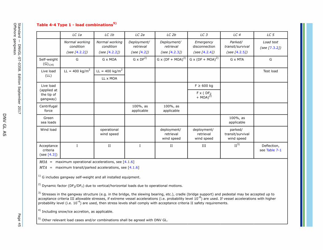
It is recommended that a sensitivity analysis is performed in order to identify all the operational and transitconfigurations (positions) of the gangway and the corresponding environmental loads, including loads due tovessel motions, acting on the gangway for each configuration. Based on this, the gangway structure shall bedimensioned for the most unfavourable condition(s).A general overview of the proposed load combinations for type 1 and type 2 gangways is presented in Table4-4 and Table 4-5.
4.2.2 Normal working conditionThe following normal working conditions are defined:
— Principal loads: self-weights and live loads as per [4.1.2].— Loads due to climatic effects: as per [4.1.5], wind speed: operational.— Loads due to motion of the vessel on which the gangway is mounted (maximum operational
accelerations), see [4.1.6].
Other relevant conditions shall be agreed with DNV GL on a case by case basis.
4.2.3 Deployment/retrieval (gangway in uplift situation)The following uplift conditions are defined:
— Principal loads: self-weights and live loads as per [4.1.2].
Guidance note 1:Live loads on gangway and waiting area assumed to be 0.
---e-n-d---o-f---g-u-i-d-a-n-c-e---n-o-t-e---
— Vertical loads due to operational motions as per [4.1.3].— Horizontal loads due to operational motions as per [4.1.4].
Guidance note 2:Unless luffing and slewing are performed at the same time, the effect of the vertical and horizontal loads needs not to becombined.
---e-n-d---o-f---g-u-i-d-a-n-c-e---n-o-t-e---
— Loads due to climatic effects: as per [4.1.5], wind speed: deployment/retrieval.— Loads due to motion of the vessel on which the gangway is mounted (maximum operational
accelerations), see [4.1.6].
Other relevant conditions shall be agreed with DNV GL on a case by case basis.
4.2.4 Emergency disconnectionThe following emergency disconnection conditions are defined:
— Principal loads: self-weights and live loads as per [4.1.2].— Live Load on gangway applied at tip.— Gangway length: maximum operational length plus safety length.— Vertical loads due to operational motions as per [4.1.3].— Loads due to climatic effects: as per [4.1.5], wind speed: deployment/retrieval.— Loads due to motion of the vessel on which the gangway is mounted (maximum operational
accelerations), see [4.1.6].
Other relevant conditions shall be agreed with DNV GL on a case by case basis.
Standard — DNVGL-ST-0358. Edition September 2017 Page 39Offshore gangways
DNV GL AS
4.2.5 Parked position/transitThe gangway is parked when completely pulled-in and supported at the free-end in a cradle/bridge rest:
— Principal loads: self-weights as per [4.1.2].— Loads due to climatic effects: as per [4.1.5], wind speed: transit/survival.— Loads due to motion of the vessel on which the gangway is mounted (maximum transit/survival
accelerations), see [4.1.6].
Additional considerations:
— Increased abrasion on part of the gangway system. The hydraulic luffing cylinders are a typical example ofparts that may be exposed to increased abrasion. During the gangway's operating condition, the hydrauliccylinders are usually exposed to less than 2 x 10⁵ load cycles. If the hydraulic cylinders are part of thesystem supporting the bridge in transport condition, they are exposed to additionally 108 load cycles dueto ship movement. Even if the loading in transport condition is smaller than those in working condition,the transport condition may, due to the large amount of cycles (500 times more cycles than that forworking condition) be of significance when considering the expected life duration of the cylinders.
— The design check of a gangway does not cover investigations whether the gangway interferes with otherequipment on-board the ship. For example, if the bridge points along the ships longitudinal axis, thetransverse displacement of the bridge tip in a storm may be significant. The ship buyer/owner should,ensure that the gangway does not interfere other equipment, not only for working condition, but also fortransport condition.
— Calculation of natural-frequencies and Eigen modes is normally not covered. The natural period of thebridge is quite different when the bridge rests in a cradle compared to when it is supported by hoistingwire and/or luffing cylinders. If, for instance, the ship movement has the same period as a natural periodfor the bridge, quite a dynamic amplification of the displacements in the bridge may occur. Additionalsecuring systems for the bridge may be required if the in-service experience of the gangway shows thatlarge vibrations may occur under transport condition.
— The vessel owner/operator shall ensure the means to secure the gangway in an out of service condition ina safe manner (e.g. lashing, etc.), however these are not covered by the gangway design review.
4.3 Strength calculations
4.3.1 GeneralIt shall be shown that structures and components have the required safety against the following types offailure:
— excessive yielding (see [4.3.2])— buckling (see [4.3.3])— fatigue fracture (see [4.3.4]).
The safety shall be evaluated for the load combinations defined in [4.2]. For each of these cases and for eachmember or cross-section to be checked, the most unfavourable position and direction of the forces shall beconsidered.The strength calculations shall be based on accepted principles of structural strength and strength ofmaterials. When applicable, plastic analysis may be used. If elastic methods are not suitable to verify safety,for instance due to pre-stressing, plastic analysis may be required.Strength requirements defined in following sections are applicable for steel and aluminium alloys. Forcomposite materials, requirements shall be specially developed for the intended use applying the technologyqualification process required by DNVGL-RP-A203 Technology qualification.The verification of safety may be based on the permissible stresses method (WSD) or the limit state method(LRFD). With the factors given in this standard there will be only a formal difference between the twomethods.
Standard — DNVGL-ST-0358. Edition September 2017 Page 40Offshore gangways
DNV GL AS
4.3.1.1 Design by LRFD method
Table 4-1 LRFD load factors
Load categoriesCombinationof loads
G Q E D
ULS a) 1.3 1.3 (xDFLL) 0.85 1.0
ULS b) 1.05 1.05 (xDFLL) 1.3 1.0
G = permanent load (self-weight of the structure and all installed equipment, vertical andhorizontal loads due to operational motions)
E = environmental load (loads due to climatic effects, loads due to motion of the vessel onwhich the gangway is mounted)
DFLL = Design factor for LL, depending on gangway type
= 1 for type 1 gangways
= 2 for types 2, 3 and 4 gangways:
D = deformation load
For steel structures, the capacity check shall normally be based on DNV GL rules and standards oralternatively other internationally recognized standards (e.g. EN 1993-1 or NORSOK). When EN 1993-1 isapplied, the material factors shall be:
— γM0 and γM1 = 1.15— γM2 = 1.3— for capacity checks where other material factors (γMi) than those defined above are used, γMi as defined
by EN 1993-1 shall be multiplied with an additional γST = 1.05. The calculated material factors shall,however, not be taken less than 1.15.
Guidance note:Material factor symbols and definitions are in accordance with EN 1993-1.
---e-n-d---o-f---g-u-i-d-a-n-c-e---n-o-t-e---
For aluminium structures, the capacity checks shall normally be based on EN 1999-1 or equivalentinternationally recognized standards. When EN 1999-1 is applied, the material factors to be used shall betaken as specified in EN 1999-1 and multiplied with an additional γAL = 1.1. The calculated material factorsshall, however, not be taken less than 1.2.The LRFD load combinations ULS a) and b) are associated with the WSD operational load cases (i.e. loadcombination LC1x and LC2x).In addition, an exceptional LRFD load combination shall be considered (corresponding to the WSD emergencyand parked/transit load cases, i.e. acceptance criteria III). The load factors shall be = 1.0, the materialfactors shall be as per [4.3.2] acceptance criteria III safety factors for steel and aluminium.The service limit state (SLS) shall be represented by the test case, see Sec.7.If capacity checks are based on other structural design standards, the material factors shall be agreed withDNV GL on a case-by-case basis. For structures with nonlinear behaviour, however, significant differencesmay occur. In such cases the limit state method shall be used, or the safety factor shall refer to load and notto stresses.
Standard — DNVGL-ST-0358. Edition September 2017 Page 41Offshore gangways
DNV GL AS
4.3.1.2 Design by WSD methodWhen using elastic analysis for cases of combined stresses, the permissible stresses (or the required safetyfactors) given in Table 4-2 refer to the equivalent stress according to von Mises. Local peak stresses in areaswith pronounced geometrical changes may be accepted on a case by case evaluation.
4.3.2 Checking with respect to excessive yielding4.3.2.1 GeneralWith reference to method of analysis and method of verification of safety given in Table 4-2, σy is theguaranteed minimum yield strength (or 0.2% proof stress). If σy is higher than 0.8 times the ultimatestrength σu, it shall be used 0.8 x σu instead of σy.Joints shall not be weaker than the minimum required strength of the members to be connected. For rivetedjoints, bolted joints, friction-grip joints, and welded joints the design shall be based on an internationallyrecognized standard.
Table 4-2 Criteria for the checking with respect to excessive yielding
Criteria for the checking with respect to excessive yielding
Method of verification Acceptance criteria I Acceptancecriteria II
4.3.2.2 AluminiumIn the case of welded connections, the respective mechanical properties in the welded condition shall beassumed. If these values are not available, the corresponding values in the soft condition shall be assumed.For aluminium structures, the safety factors in Table 4-2 shall be multiplied with an additional safety factor,SFAL = 1.05.
4.3.3 Checking with respect to bucklingThe guiding principle is that the safety against buckling shall be the same as the required safety against theyield limit load being exceeded. This principle indicates that the safety factors given in the third line of Table4-2 should represent the normal requirement. These are based on the assumption that the critical stresses(or loads) are determined by recognized methods, taking possible effects of geometrical imperfections andinitial stresses into account.However, other values may be required or allowed, for instance due to uncertainty in the determination of thecritical stresses (or load) or due to the post-buckling behaviour. Required factors are given for various typesof buckling in Table 4-3. Elastic buckling in Table 4-3 means that elastic buckling stress does not exceed theyield strength.Calculation methods and corresponding required safety factors as specified by other internationallyrecognized standards for structural design may also be used.
Table 4-3 Safety factors for the checking with respect to buckling
Safety factors for the checking with respect to buckling
Type of buckling Acceptance criteria I Acceptance criteria II Acceptance criteria III
Elastic buckling 1.86 1.66 1.38
Standard — DNVGL-ST-0358. Edition September 2017 Page 42Offshore gangways
DNV GL AS
Safety factors for the checking with respect to buckling
Elastic-plastic buckling 1.69 1.51 1.25
4.3.4 Checking with respect to fatigueChecking with respect to fatigue shall be based on an internationally recognized standard applicablefor structures intended to be used offshore (e.g. DNVGL-RP-C203, DNVGL-CG-0129, etc.). The fatigueassessment shall be performed on the gangway structure considering the cumulative damage effects of boththe operational (including deployment/retrieval) and transit/parked cases and shall consider (but not limit to)the following gangway specifics:
— Operation time: not less than 20 years— Translation and/or rotation cycles in the directions/around X, Y and Z axis (e.g. telescoping, luffing,
slewing, etc.)— Loads due to motion of the vessel on which the gangway is mounted— Wind load may usually be excluded— Type 1 only: on and off-load cycles at full live load: not less than 6/day (e.g. 3 working shifts).
Guidance note:
1) On-load: gangway subject to full LL
2) Off-load: gangway completely unloaded (LL=0).
The on and offload cycles shall be agreed with DNV GL and be noted in the certificate.
---e-n-d---o-f---g-u-i-d-a-n-c-e---n-o-t-e---
— Deployment/retrieval cycles/day.— The design fatigue factor (DFF) shall not be less than 2 (for definition of DFF see DNVGL-OS-C101).— The load combinations for the fatigue assessment can be based on the load combinations defined in Table
4-4 and Table 4-5 (as applicable).— Stress acceptance levels according to the fatigue standard used.
The stress range spectrum shall be defined by the designer considering the above minimum limitations.Different fatigue design parameters shall be agreed with DNV GL on a case by case basis.For the gangway pedestal below the slewing ring, in addition to the above defined conditions, theintroduction of relative stress in the pedestal caused by global deformation of the asset shall also beevaluated, if relevant.
4.3.5 Design and strength of components4.3.5.1 GeneralComponents part of the primary load path that are not directly or completely covered by this standard shallbe designed and calculated in accordance with applicable internationally recognized codes or standards.
4.3.5.2 Slewing bearings and flangesSlewing bearings and flanges shall be designed based on the same loads as for the gangway and as per themethology in DNVGL-ST-0378 [4.4.3] and [4.4.4]. The additional offshore safety factor SF1, see DNVGL-ST-0378 [8.2.2.4], is not required for offshore gangways.
4.3.5.3 Pedestals and pedestal adaptersPedestals and pedestal adapters shall be designed based on the same loads as for the gangway.Telescopic pedestals shall also fulfil the requirements in [6.3.8.2].
Standard — DNVGL-ST-0358. Edition September 2017 Page 43Offshore gangways
DNV GL AS
4.3.5.4 Wheel rolling on rail/structureCalculation of stress shall be done as per EN 13001-3-1 annex C.4.EN 1993-6 part 5 or other applicable internationally recognized standards shall be used if the wheel andrunway beam design is not covered in EN 13001-3-1 annex C.4. These standards shall be agreed with DNVGL.Alternatively, FE calculations shall be provided.
4.3.5.5 Hydraulic cylindersLoad carrying hydraulic cylinders (i.e. cylinders part of the luffing and telescoping systems) shall fulfil therequirements in DNVGL-CG-0194 Hydraulic cylinders.Where cylinders are used for luffing and/or telescoping, each motion shall have two independent cylinders,with each cylinder being capable of holding the design loads. Alternatively, a single cylinder may be used,provided that no single point failure can lead to uncontrolled motion, see [6.3.8.2].The design calculations for hydraulic cylinders shall be based on the maximum obtainable pressure (safetyvalve setting). Alternatively, if the maximum dynamic force applied on the gangway is known, this may beused as basis for the design calculations. In both cases different outreach positions shall be evaluated.Based on case by case considerations, a safety factor with respect to buckling down to 2.3 may be acceptedfor slenderness ratios above 110 when applying detailed calculations. For slenderness ratios below 90,buckling is not considered and a safety factor of 1.8 with respect to yield stress will be required. Forslenderness ratios between 90 and 110, linear interpolation between the two above acceptance criteria shallbe applied.
4.3.5.6 WinchesWinches used for luffing or telescoping shall be designed based on DNVGL-ST-0378 [5.2] and DNVGL-ST-0378 Sec.11 requirements for offshore cranes. Alternative solutions may be considered based ondocumented equivalent safety level on specific applications.
4.3.5.7 Drive componentsDrive components (e.g. gears transmitting braking forces) shall be designed according to DNVGL-ST-0378requirements considering the specific use of the gangway and consequences in case of failure (see also[6.3.8]). The transmission components shall be considered as brake components.The hoisting or luffing drive systems shall primarily be designed to hold at least 1.5 times the design torquecaused by environmental and operational (including inertia) loads.The slewing and telescoping drive systems shall primarily be designed to hold at least 1.3 times the designtorque caused by environmental and operational (including inertia) loads.The drive systems shall consist of a minimum of two drive units.
Guidance note:A single drive unit is acceptable provided failure of the drive unit and its control system will not cause uncontrolled movement ofthe gangway.
---e-n-d---o-f---g-u-i-d-a-n-c-e---n-o-t-e---
4.3.5.8 Wire ropes and chainsWire ropes used for luffing, telescoping and hoisting the gangway and/or its support structure while thegangway is manned shall have a safety factor, measured against the minimum specified breaking load(MBL), not less than 8 with respect to the wire rope design load. Lower safety factors may be accepted in thefollowing conditions:
— Redundant hoisting/telescoping/luffing wire ropes, minimum SF=5 for each wire rope.— The gangway telescoping segment is prevented from falling inside/outside the fixed segment by means of
end stops, minimum SF=5 (for the telescoping wire rope).— The gangway and/or its support structure is physically locked at the operational elevation (i.e. hoisting
wire rope not part of the load path), minimum SF=5 (for the hoisting wire rope).
With reference to above provisions, the safety factors for chains shall not be less than 6 or 4, respectively.
Standard — DNVGL-ST-0358. Edition September 2017 Page 44Offshore gangways
DNV GL AS
4.4 Design loads type 1 gangwaysType 1 gangways shall normally be evaluated based on the load combinations defined in [4.2]. Other designspecific loads and load combinations shall be evaluated on a case-by-case basis.Type 1 specific design requirements are:
— Normal working condition:
— Live load on the gangway 400 kg/m2, where live load shall be evenly distributed across the effectiveload area of the gangway and:
— width of gangway for calculating the load shall be the clear width— length of loaded gangway shall be the maximum operational length without the safety length.
— Emergency disconnection:
— Live load on the gangway tip 600 kg.
Below Table 4-4 summarizes the load combinations and acceptance criteria for type 1 gangways.
Standard —
DN
VG
L-ST-0358. Edition S
eptember 2017
Page 45O
ffshore gangways
DN
V G
L AS
Table 4-4 Type 1 - load combinations5)
LC 1a LC 1b LC 2a LC 2b LC 3 LC 4 LC 5
Normal workingcondition
(see [4.2.2])
Normal workingcondition
(see [4.2.2])
Deployment/retrieval
(see [4.2])
Deployment/retrieval
(see [4.2.3])
Emergencydisconnection
(see [4.2.4])
Parked/transit/survival
(see [4.2.5])
Load test
(see [7.3.2])
Self-weight(G)1)4)
G G x MOA G x DF2) G x (DF + MOA)2) G x (DF + MOA)2) G x MTA G
LL = 400 kg/m2Live load(LL)
LL = 400 kg/m2
LL x MOA
Test load
F ≥ 600 kgLive load(applied atthe tip ofgangway)
F x ( DFZ+ MOA)2)
Centrifugalforce
100%, asapplicable
100%, asapplicable
Greensea loads
100%, asapplicable
Wind load operationalwind speed
deployment/retrieval
wind speed
deployment/retrieval
wind speed
parked/transit/survival
wind speed
Acceptancecriteria
(see [4.3])
I II I II III II3) Deflection,see Table 7-1
MOA = maximum operational accelerations, see [4.1.6]
MTA = maximum transit/parked accelerations, see [4.1.6]
1) G includes gangway self-weight and all installed equipment.
2) Dynamic factor (DFZ/DFY) due to vertical/horizontal loads due to operational motions.
3) Stresses in the gangway structure (e.g. in the bridge, the slewing bearing, etc.), cradle (bridge support) and pedestal may be accepted up toacceptance criteria III allowable stresses, if extreme vessel accelerations (i.e. probability level 10-8) are used. If vessel accelerations with higherprobability level (i.e. 10-4) are used, then stress levels shall comply with acceptance criteria II safety requirements.
4) Including snow/ice accretion, as applicable.
5) Other relevant load cases and/or combinations shall be agreed with DNV GL.
Standard — DNVGL-ST-0358. Edition September 2017 Page 46Offshore gangways
DNV GL AS
4.5 Design loads type 2 gangways
4.5.1 GeneralType 2 gangways shall normally be evaluated based on the load combinations defined in [4.2]. Other designspecific loads and load combinations shall be evaluated on a case-by-case basis.Type 2 specific design requirements are:
— Normal working condition:
— the gangway shall be designed according to the most onerous of the 2 below scenarios.
— Live load (LL) on the gangway shall be the maximum number of persons, including hand tools/luggage, allowed on the gangway at the same time. The actual distribution of the LL along thegangway (as specified in the gangway's operational manual) shall be used for calculations.
— Live load on the gangway tip 120 kg, gangway in uplift/cantilever position.
— The design load shall be 2 x live load.— Length of loaded gangway is the maximum operational length without the safety length.— Vertical and horizontal (longitudinal/transverse) bumper/push loads, as applicable.
— Emergency disconnection:
— Live load on the gangway tip: minimum 350kg (equivalent to a minimum of 2 persons and a person inthe stretcher).
— Gangway in uplift/cantilever position.— Length of loaded gangway is the maximum operational length without the safety length.
4.5.2 Full motion compensated gangwaysAs a general principle, these shall be designed according to the requirements in [4.5.1] with stressacceptance levels according to acceptance criteria III (accidental load case is when the motion compensatingsystem is out of service).In addition, the gangway shall also be calculated for LC 1a and LC 2a in Table 4-5.
Standard —
DN
VG
L-ST-0358. Edition S
eptember 2017
Page 47O
ffshore gangways
DN
V G
L AS
Table 4-5 Type 2 - load combinations6)7)
LC 1a LC 1b LC 1c LC 2a LC 2b LC 3 LC 4 LC 5
Normal workingcondition
(see [4.2.2])
Normal workingcondition
(see [4.2.2])
Normal workingcondition
(see [4.2.2])
Deployment/retrieval
(see [4.2.3])
Deployment/retrieval
(see [4.2.3])
Emergency
disconnection
(see [4.2.4])
Parked/transit/survival
(see [4.2.5])
Load test
(see [7.3.2])
Self-weight(G)1)5)
G G x MOA G x MOA G x DF2) G x (DF+ MOA)2)
G x (DF+ MOA)2)
G x MTA G
LL LL min. 120kg4)Live load(LL)
2 x LL 2 x LL x MOA 2 x LL x MOA
Test load
F ≥ 350kgLive load(applied atthe tip ofgangway)
F x (DFZ+ MOA)2)
Bumperloads
(vertical,longitudinal,transverse)
100%, asapplicable
100%, asapplicable
Centrifugalforce
100%, asapplicable
100%, asapplicable
Greensea loads
100%, asapplicable
Wind load operationalwind speed
operationalwind speed
deployment/retrieval
wind speed
deployment/retrieval
wind speed
parked/transit/survival
wind speed
Acceptancecriteria
(see [4.3])
I II II I II III II3) Deflection,see Table 7-1
Standard —
DN
VG
L-ST-0358. Edition S
eptember 2017
Page 48O
ffshore gangways
DN
V G
L AS
MOA = maximum operational accelerations, see [4.1.6]
MTA = maximum transit/parked accelerations, see [4.1.6]
1) G includes gangway self-weight and all installed equipment.
2) Dynamic factor (DFZ/DFY) due to vertical/horizontal loads due to operational motions.
3) Stresses in the gangway structure (e.g. in the bridge, the slewing bearing, etc.), cradle (bridge support) and pedestal may be accepted uptoacceptance criteria III allowable stresses, if extreme vessel accelerations (i.e. probability level 10-8) are used. If vessel accelerations with higherprobability level (i.e. 10-4) are used, then stress levels shall comply with acceptance criteria II safety requirements.
4) Gangway in uplift position (cantilever), load applied at the free end (tip).
5) Including snow/ice accretion, as applicable.
6) Other relevant load cases and/or combinations shall be agreed with DNV GL.
7) Fully motion compensated gangways shall have special consideration. Not all load combinations and stress acceptance levels in the table are directlyapplicable.
Standard — DNVGL-ST-0358. Edition September 2017 Page 49Offshore gangways
DNV GL AS
SECTION 5 FUNCTIONAL REQUIREMENTS
5.1 GeneralGenerally, the gangway structure shall be designed so that the critical areas (joints, connections with thesupporting structure, sliding surfaces and arrangements, wheels and rails, etc.) shall be easily accessible forregular inspection and maintenance.
5.2 Machinery
5.2.1 Design conditions (environmental, operational) for machinery andsystemsMachinery and systems for offshore gangways shall be designed to operate under marine environmentalconditions, with ambient air temperatures matching the gangway design temperature (see [3.2]). If nototherwise specified in the detail requirements for the component or system:
— ambient air temperature between the design temperature, see [3.2], and 35°C— ambient air temperature inside machinery housing or other compartments containing equipment between
5°C and 55°C— relative humidity of air up to 96%.For gangways designed to be used on vessels with Ice or Winterization class notation, the requirements inDNVGL-RU-SHIP Pt.6 Ch.6 or DNVGL-OS-A201 (as applicable) shall be considered as a minimum.
5.2.2 MaterialsThe applied material standards shall comply with Sec.3 or other relevant recognised code or standard.Materials with high heat resistance shall be applied where a fire may cause unacceptable consequences ofdamage, such as collapse, outflow of flammable fluids etc.Non-metallic materials shall be flame-retardant in accordance with recognised standard.
5.2.3 Arrangement and general design of components and equipmentAll components in a system shall be adequately matched with regard to strength, capacity and functionalperformance.Relative movements due to load variations, thermal expansion, misalignment, vibration and interaction fromfoundations shall be allowed to avoid detrimental effects.Bolts and nuts exposed to dynamic forces and vibrations shall be properly secured or pre-stressed.All operational equipment shall be arranged for easy access. Components and equipment normally subject toinspection and maintenance shall be installed to provide easy access.Arrangement for adequate lubrication of bearings and gears shall be provided.Protection against rain, sea-spray, snow, ice and sand shall be provided (essential for brakes, clutches etc.).Provisions shall be made to prevent accumulation of water in any construction. Rapid drainage shall beensured.Gangway seatings and their supporting structures shall be of rigid design. Tolerances of mating surfaces ofseatings shall meet the standard required by the manufacturer of the slewing ring and general engineeringstandards.
Standard — DNVGL-ST-0358. Edition September 2017 Page 50Offshore gangways
DNV GL AS
5.2.4 VentilationForced ventilation (heating/cooling) shall be provided, when necessary, to ensure inside temperatureswithin the range required by [5.2.1]. Higher temperatures may be accepted provided installed equipment isregarded as suitable for such higher temperature.Verification of temperature and final acceptance shall be based on the gangway's operational live load andsequence.
5.2.5 StrengthThe strength of components and equipment shall generally comply with Sec.4. If acceptable accuracy cannotbe obtained by strength calculations, special tests may be required for determination of the strength of adesign.
5.3 Walking heightFree walking height shall be a minimum of 2.1 meters.
5.4 Clear widthClear width shall be at least 1.2 meters for type 1 gangways. For type 2 gangways, a minimum clear widthof 0.60 meters shall be required for allowing transportation of injured personnel by means of standardstretchers if not otherwise agreed with DNV GL.
5.5 WalkwayThe surfaces of the walkway, treads and steps shall be of/coated with hard-wearing, oil resistant non-slipsurface/coating.Any features that could represent a tripping hazard for the persons crossing the gangway (e.g. pipe/cableguides, etc.) shall be avoided.Toe boards not less than 100 mm high shall be fitted on either side of the walkway. Alternative arrangementsshall be considered provided that they ensure at least the same safety and functional requirements.The walkway shall be designed for drainage and easy cleaning of contaminants like mud and oil. A clearanceof maximum 10 mm between the toe board and walkway shall be ensured.When people might be present below the walkway while the gangway is in operation, the maximum size ofthe grating openings shall be selected considering the hazards caused by objects or other materials falling orpassing through the flooring. However, the opening size shall not allow a 20 mm sphere to pass through.
5.6 HandrailsHandrails shall be in form of a protecting grid or railing, min. 1.0 m high on both sides:
— Stanchions shall be spaced not more than 1.5 m apart.— Handrails shall have at least 3 courses. The openings below the lowest course of the handrails shall not
exceed 230 mm. The other courses shall be not more than 380 mm apart.
The stanchions and handrails shall be designed for a side loading at the upper guide level of 75 kg/m (loadcase III). The global effect of the above defined side load on the gangway primary structure shall also beconsidered for the operational case LC 1b.Handrails shall have smooth surfaces. Edges shall have radii (minimum 2 mm) or be chamfered (minimum 2x 2 mm). Alternative arrangements shall be considered provided that the safety level achieved is similar orhigher.
Standard — DNVGL-ST-0358. Edition September 2017 Page 51Offshore gangways
DNV GL AS
5.7 Access to gangway and waiting areaThe structural strength requirements of the waiting area and its access, as well as their connections with thegangway structure, shall be based on the below criteria.If the gangway is designed with a personnel waiting area attached to or otherwise supported by thegangway, the design load for this area shall be 400 kg/m2. The design loads for the waiting area shall beconsidered when evaluating the strength of the main structure of the gangway.The access to the gangway and/or waiting area (in form of a stairway, a dedicated small gangway/ramp orthe gangway itself) shall be designed for a load not less than 400 kg/m2 (but not less than 100 kg applied inthe most onerous position) or 100 kg/step applied as a central point load on every step.The handrails shall be able to withstand an impact force of 50 kg/m at the upper level without permanentdeformation.The clear width of the main access to the gangway shall be correlated with the clear width of the gangway,see [5.4] , and the expected number of persons to be evacuated in case of an emergency.
Guidance note:
i) For gangways with high LL, such as type 1 gangways, the main access should typically be at least as wide as required in [5.4],especially if the access is in form of stairs with multiple flights.
ii) It is recommended that the design of the access to the gangway and waiting area, in terms of dimensional and layoutrequirements, complies with international recognized standards/codes (e.g. EN-13586 for type 1 access, NORSOK C-002,etc.).
iii) It is recommended that the main access to/from the gangway to be ensured by means other than ladders.
---e-n-d---o-f---g-u-i-d-a-n-c-e---n-o-t-e---
Gangways for which an elevator represents the main access shall be arranged with emergency escape. Fixedladders may be accepted in connection to the use of portable escape equipment (e.g. safety harness). Theaccess and waiting areas of gangways shall be designed and located such that the consequences associatedwith a failure in an equipment or component part of the gangways power system (e.g. fire, hydraulicdischarge, etc.) do not represent a risk to any persons using these spaces.Protection shall be ensured by physical means (e.g. protective panels) or proximity. Hazards due to externalpower generators, hydraulic supplies and associated equipment (i.e. located in the proximity of the gangway)shall also be considered.In addition to the above, access (including any stairs at either or both ends) to the gangway shall beaccording to applicable requirements in SOLAS, flag state, shelf state and class requirements.
5.8 Protecting gridThere shall be adequate protection at locations of relative movement between gangway sections to preventinjury to parts of the human body. These shall be highlighted and marked using high visibility paint.The minimum size of the gaps below which the hazard of crushing parts of the human body is consideredacceptable shall be calculated based on an internationally recognized standard (e.g. EN 349).
5.9 LightingLighting shall be arranged for the entire gangway (including the access to gangway, see [5.7]) and landingplatform with stairs, at locations of relative movement between gangway sections, as well as at the ends ofthe gangway).
Standard — DNVGL-ST-0358. Edition September 2017 Page 52Offshore gangways
DNV GL AS
Guidance note:
1) Recommended illumination at floor level for normal operation should not be less than 100 lux, 25 lux when powered fromemergency generator or 15 lux when powered from battery in case of main power supply failure.
2) Lighting mounted on gangway fixed end (e.g. vessel side) may be substituted by the supporting vessel's illuminating system,provided that the visibility and safety levels are properly documented.
---e-n-d---o-f---g-u-i-d-a-n-c-e---n-o-t-e---
The illuminating system shall be so designed so that a single failure, e.g. in the gangway electrical system, ofa single light or cut in a lighting strip, etc. shall not affect its functionality.
Guidance note:The illuminating system redundancy may be ensured by means of dual electrical supply, battery packs installed on each lightfixture or strip, etc.
---e-n-d---o-f---g-u-i-d-a-n-c-e---n-o-t-e---
5.10 Operator's cabinIf required or fitted, the cabin shall satisfy the following overall requirements:
— be of adequate size and give adequate protection against weather and other environmental exposure— give the operator an adequate view of the area of operation— have windows capable of being readily and safely cleaned inside and outside and to have defrosting and
defogging means, shall have windscreen wipers fitted to all windows necessary for the gangway operator'sfree view when operating the gangway
— be adequately tempered (heated, cooled) and ventilated according to local conditions— be of fireproof construction, have doors that can be readily opened from both inside and outside— noise and vibration shall remain within acceptable limits.
Guidance note:It is recommended that noise level is kept under 80 dB inside the cabin.
---e-n-d---o-f---g-u-i-d-a-n-c-e---n-o-t-e---
— have a comfortable and purpose-designed seat from which all operations can easily be controlled. Footrests shall be arranged where necessary
— have the gangway controls marked and lit to show their respective function.Guidance note:It is recommended that the design complies with international recognized standard/code (e.g. EN-13557).
---e-n-d---o-f---g-u-i-d-a-n-c-e---n-o-t-e---
5.11 Landing area
5.11.1 Gangway supported at both endsFor gangways supported at both ends in X, Y, and/or Z axis directions, the landing area shall be arranged toprevent unacceptable movement. This may include a platform for providing support in Z axis direction, sidestoppers or equivalent arrangements to prevent unacceptable sideways movements. Other arrangementsshall be agreed with DNV GL.
Guidance note:Side stopper may be a physical structure or lashing.
---e-n-d---o-f---g-u-i-d-a-n-c-e---n-o-t-e---
Standard — DNVGL-ST-0358. Edition September 2017 Page 53Offshore gangways
DNV GL AS
Design features to prevent unacceptable movement (e.g. platform, side stoppers, etc.) shall be dimensionedfor a design load of twice the resultant loads in X, Y, and Z axis directions at the gangway tip due to:
— gangway self-weight and live loads— loads due to climatic effects, see [4.1.5]— loads due to motion of the vessel on which the gangway is mounted/supported, see [4.1.6].
The gangway shall be fitted with a break-away system (see [6.3.1.3]).
5.11.2 Gangway supported at one end only (cantilever)For gangways designed to operate as a cantilever, the gangway shall be equipped with a system to hold thegangway end in constant position in X, Y and Z axis directions (e.g. motion compensation system). Toleranceshall not be more than +/- 100 mm unless suitable protection to prevent personal injury is installed. Thealternative solution shall be documented by means of risk identification and physical testing proving anequivalent safety level.In addition, the gangway shall be designed for an upward vertical load and horizontal loads (in direction of Xand Y axis) according to [4.5] (as applicable). See also [6.3.1.2].
5.11.3 Gangway supported at both ends (gangway tip in light contact withsupporting structure)For such gangways, the provisions in [5.11.1] and [5.11.2] shall be followed, as applicable.
5.12 Operation angle
5.12.1 GeneralNormally, a gangway is classified as a ramp. The maximum operational angle amplitude/range to thehorizontal for the gangway shall be ±10 degrees. Up to ±20 degrees may be used if the gangway is fittedwith enhanced slip resistance features.
Guidance note:Steeper operational angles may be considered provided that the deck of the gangway is fitted with treads or steps, see ISO 14122.The specific requirements shall be agreed with DNV GL.
---e-n-d---o-f---g-u-i-d-a-n-c-e---n-o-t-e---
5.12.2 Tread designAll treads shall be securely fitted, and shall extend over the full width of the gangway between the toeboards. Provision should be made for easy cleaning of the gangway between the treads, by leaving a 25 mmspace between tread and toe board at each side. Liquids shall not gather between the treads.
— Spacing: at regular intervals, not more than 400 mm (in X axis direction).— Height: not less than 30 mm above the walkway.
5.13 Power systemThe main gangway functions (slewing, luffing and telescoping) shall have such response to the controls thatthe minimum required speed from stand still shall be obtained within 2 seconds from activation of the controllever. The control levers shall have predictable smooth motions proportional to their position.
Standard — DNVGL-ST-0358. Edition September 2017 Page 54Offshore gangways
DNV GL AS
The gangway shall have enough power to be able to perform its functions (slewing, luffing and telescoping)with adequate speed, thus enabling it to connect/maintain its position relative to the landing area in a safeand quick manner.The gangway shall be connected to an independent emergency power source, rated to handle the gangwayat full LL, i.e. luffing, slewing, telescoping and full functionality under all conditions. The emergency powersource may be a redundant main power supply, an emergency power supply from the installation or a stand-alone emergency power supply in the gangway.For operation within hazardous (gas-dangerous) areas, prime movers and their installation shall meetadditional pertinent requirements.Adequate insulation and shielding shall be provided for the protection of personnel during performance oftheir normal duties and to prevent ignition of flammable fluids.Internal combustion engines shall normally not be located in hazardous areas. The exhaust gas outlet of theengines shall have an effective spark arrester. The outlet shall be led to the atmosphere at a safe distancefrom any hazardous area.
5.14 Electrical installations, equipment and systemsElectrical installation shall comply with relevant and recognized codes or standards pertinent to the locationof the gangway.The electrical equipment and systems supporting the gangway main functions shall comply with DNVGL-RU-SHIP Pt.4 Ch.8 and will be defined as essential. Specifically, equipment and systems having impact on thesafety and safety equipment requirements listed in Sec.6 shall fulfil requirements with respect to essentialinstallations. However, the documentation requirements are given in [2.1.1] and certification requirementsare provided below.All electrical equipment part of the control and/or safety system shall be type approved by an internationallyrecognized certification body, documenting suitability for the intended application in a marine environment.
Guidance note:The requirement normally applies to the following components:
— switchboards
— motor starters and frequency converters, electric motors
— slip rings
— generators and transformers
— cables, termination accessories
— other components that may be essential for the electrical system functionality.
---e-n-d---o-f---g-u-i-d-a-n-c-e---n-o-t-e---
For gangways on-board mobile offshore units (semi submersibles, jack-ups, etc.), additional requirements asspecified by the governing DNV GL rules for classification: Offshore units (RU-OU) shall be applied.
Guidance note:Relevance of the additional requirements may be agreed with DNV GL on a case-by-case basis.
---e-n-d---o-f---g-u-i-d-a-n-c-e---n-o-t-e---
5.15 Hydraulic systems
5.15.1 GeneralHydraulic systems and their lay-out shall be in accordance with DNVGL-RU-SHIP Pt.4 Ch.6. Alternatively,compliance with other internationally recognized standards shall be agreed with DNV GL on a case by casebasis during design review.
Standard — DNVGL-ST-0358. Edition September 2017 Page 55Offshore gangways
DNV GL AS
When designing hydraulic circuits, all aspects of possible methods of failure (including control supply failure)shall be considered. In each case, components shall be selected, applied, mounted and adjusted so thatin the event of a failure, maximum safety to personnel shall be the prime consideration, and damage toequipment minimized (fail-safe concept).All parts of the system shall be designed or otherwise protected against pressures exceeding the maximumworking pressure of a system or any part of the system or the rated pressure of any specific component.Systems shall be designed, constructed and adjusted to minimize surge pressures and intensificationpressures. Surge pressure and intensified pressure shall cause no hazards.Loss of pressure or critical drops in pressure as well as missing hydraulic refilling and leakage (internal orexternal) shall not cause a hazard.Whatever type of control or power supply used (e.g., electrical, hydraulic, etc.), the following actions oroccurrences (unexpected or by intention) shall create no hazard:
— switching the supply on or off— supply reduction— supply cut-off or re-establishment.
Hydraulic systems and other machinery in connection with the hydraulic system shall be designed to protectpersonnel from surface temperatures that exceed touchable limits by either insulating or guarding.To facilitate maintenance, means shall be provided or components so fitted that their removal from thesystem for maintenance:
— shall minimize the loss of fluid— shall not require draining of the reservoir— shall not necessitate extensive disassembly of adjacent parts.
The fluid reservoir shall be designed with respect to:
— dissipation of heat from the oil— separation of air— settling of contamination in the oil— maintenance work.
Indicators showing the fluid level shall be permanently marked with system high and low levels.Air breathers on vented reservoirs should be provided which filter air entering the reservoir to a cleanlinesslevel compatible with the system requirements, taking into consideration the environmental conditions inwhich the system shall be installed.Effective means for filtration and cooling of the fluid shall be incorporated in the system. A means ofobtaining a representative fluid sample shall be provided to allow for checking fluid cleanliness condition.Valves for fluid sampling shall be provided with sealing and with warning signs marked system underpressure.
5.15.2 Flexible hosesFlexible hoses and couplings shall be of approved type with work product certificate level documentation(type approval certificate issued by DNV GL is recommended). Flexible hoses shall only be used:
— between moving elements— to facilitate the interchange of alternative equipment— to reduce mechanical vibration and/or noise.
Flexible hoses shall be located or protected to minimize abrasive rubbing of the hose cover.
5.15.3 Hydraulic cylindersSpecific design requirements for hydraulic cylinders to be installed on offshore gangways are listed in[4.3.5.5].
Standard — DNVGL-ST-0358. Edition September 2017 Page 56Offshore gangways
DNV GL AS
5.15.4 TestingEach component shall be pressure tested to 1.5 times the design pressure, except for mountings which shallbe tested at 2 times the design pressure. The test pressure needs not to exceed the design pressure by morethan 70 bar.Hydraulic testing of the gangway hydraulic system shall be performed in the presence of a surveyor, unlessotherwise agreed. The pressure from the overload testing is deemed sufficient and shall be maintained for atime sufficient for check of leakage. The hydraulic system shall exhibit no sign of defects or leakage.Hydraulic cylinders shall be tested in accordance with DNVGL-CG-0194 requirements.
5.16 Pneumatic systemsAir intakes for compressors shall be so located as to minimize the intake of oil- or water contaminated air.When designing pneumatic circuits, all aspects of possible methods of failure (including control supply failure)shall be considered. In each case, components shall be selected, applied, mounted and adjusted so thatin the event of a failure, maximum safety to personnel shall be the prime consideration, and damage toequipment minimized (fail-safe concept).Loss of pressure or critical drops in pressure, as well as leakage (internal or external) shall cause no hazard.Whatever type of control or power supply used, the following actions or occurrences (unexpected or byintention) shall not create a hazard:
— switching the supply on or off— supply reduction— supply cut-off or re-establishment.
Air supply to instrumentation equipment shall be free from oil, moisture and other contaminants. The dewpoint shall be below 5°C for air in pipes located in gangway engine room. In pipes outside the engine roomthe air shall have a dew point below (TD-5)°C.Components requiring extremely clean air shall not be used.Main pipes shall be inclined relative to the horizontal, and drainage shall be arranged. Piping and pressurevessels shall comply with DNVGL-RU-SHIP Pt.4 Ch.6 or other relevant internationally recognized codes andstandards.
5.17 Control and monitoring systems
5.17.1 GeneralAll gangways shall be provided with safety functions reducing the risk connected to personnel transferoperations, therefore control and monitoring systems supporting the gangway safety functions shall bedesigned with respect to redundancy, robustness against single failures and availability.The control system shall be designed based on the generic principles specified in DNVGL-RU-SHIP Pt.4Ch.9, the functional requirements in [5.17], [5.18] and safety requirements in Sec.6. The documentationrequirements are given in [2.1.1]and certification requirements are provided below.The main components for control, monitoring and safety systems shall be type approved by an internationallyrecognized certification body, documenting suitability for the intended application in a marine environment.
Standard — DNVGL-ST-0358. Edition September 2017 Page 57Offshore gangways
DNV GL AS
Guidance note:The requirement normally applies to the following components:
— controllers, PLCs
— I/O cards, communication cards
— operator stations, computers
— network switches, routers, firewalls
— other components that may be essential for the control system functionality.
---e-n-d---o-f---g-u-i-d-a-n-c-e---n-o-t-e---
Control system design and components shall therefore be selected, applied, mounted and adjusted so that inthe event of a failure, personnel safety shall be the prime consideration (fail-safe concept).The testing program shall follow the requirements in [7.2.4].
5.17.2 Wireless remote control systemsThe wireless remote control shall be designed, built and tested following the same principles applicable to thehardwired control station, see [5.171].Further, specific requirements for wireless control devices shall be complied with:
— The wireless communication with the gangway shall comply with the technical requirements in DNVGL-RU-SHIP Pt.4 Ch.9 Sec.4 [3].
— Loss of communication with the remote control shall cause the gangway to go into a safe state as outlinedin [5.17.1]. The error shall trigger an acoustic alarm.
— By starting of the remote control unit, a self-check shall be conducted in order to prevent movements ifthe control has been left in such mode.
— The remote control unit shall be provided with a key-switch for closing when not in use.— The remote control unit shall also be provided with a dead man button.
Should a gangway be possible to be controlled from multiple workstations (e.g. the hardwired control stationand the wireless remote control), the following shall apply:
— Only one workstation shall be in control at any one time.— Control shall not be transferred before being acknowledged by the receiving workstation.— Transfer of control shall give an audible pre-warning.— It shall be indicated at each alternative workstation, which control station holds the command rights.— Failure of the remote control shall initiate an audible and visual alarm and shall not prevent and
immediate normal manual control from the hardwired control station.
5.18 Control and monitoring systems for active motioncompensating gangways
5.18.1 GeneralFor gangways fitted with an active motion compensating (AMC) system which is operational duringnormal working condition/personnel transfer, the control and monitoring system shall fulfil the followingrequirements, in addition to the provisions in [5.17].AMC gangways shall be designed and built based on a fail-safe concept.
5.18.2 Fail-operational gangwaysGenerally, the safety philosophy shall be based on a fail-operational concept, where redundancy in the AMCcontrol system supporting both main and safety functions will be required. Specific requirements for suchsystems are further defined in below sections. Testing shall follow the requirements in [7.2.4].
Standard — DNVGL-ST-0358. Edition September 2017 Page 58Offshore gangways
DNV GL AS
5.18.2.1 Redundancy and failure modesRedundancy of active components (e.g. cylinders, winches, gears, etc.) is generally not required if adequatereliability can be documented, the part is protected from mechanical damage (e.g. overloading) and subjectto a regular inspection and maintenance regime.For the AMC control system, the design and level of redundancy employed in system arrangements shall beto the extent that the gangway maintains the ability to actively compensate vessel motions after a singlefailure of a component or subsystem for sufficient time, emergency operational time, to safely abort thepersonnel transfer operation (i.e. to allow all persons crossing the gangway to evacuate to a safe zone, toalert/inform nearby personnel that the gangway is no longer safe to use and to bring the gangway to a safestate, see [6.2.1] and [6.2.2]).In addition, the AMC function of the gangway shall not be affected by any failure in the power system(electric or hydraulic).
Guidance note:Typically, the emergency operational time should be not less than 60 s.
---e-n-d---o-f---g-u-i-d-a-n-c-e---n-o-t-e---
The AMC control system design philosophy shall describe the main features of the design and identify theredundancy design intent (including the separation design intent when required).Consequences of single failures in accordance with rule requirements shall be documented in the form of afailure mode and effect analysis (FMEA).
5.18.2.2 Failure mode effect analysis (FMEA)The main purpose of the FMEA is normally to demonstrate that redundant systems are not degraded beyondacceptable performance criteria after a single failure. The FMEA shall normally consist of the following parts,(see DNV-RP-D102):
— general system information— specification of acceptance criteria— specification of the overall boundary of the system/unit subject to the FMEA— redundancy design intent, worst case failure design intent, time requirements, and gangway operational
modes— specification of all redundant components and single component groups included within the overall system
boundary. The relevant system names, main units, compartments (when applicable), and their mainintended functions shall be presented in a structured manner, supported with a descriptive narrative text
— specification of all assumptions related to systems interfaces and dependencies of external systems— single failure and common cause analysis at unit and subsystem levels, including consequence for the
function and eventual manual/automatic corrective actions assumed— summary and conclusions— a redundancy and failure mode test program specifying tests to verify assumptions and conclusions shall
be developed— a compliance statement referring to the overall system boundary, operational modes, tests, and
acceptance criterion including time requirements shall be stated for the FMEA.The requirements to FMEAs for redundant systems differ from traditional bottom up FMEAs in the followingrespects:
— requirement to state the redundancy design intent— requirements to specification of acceptance criterion to be complied with— requirements to refer to full scale testing to support analysis— requirements to state compliance with the acceptance criterion. The FMEA documentation shall be self-
contained and provide sufficient information to get the necessary overview of the system.
Standard — DNVGL-ST-0358. Edition September 2017 Page 59Offshore gangways
DNV GL AS
5.18.3 Fail-passive gangwaysAlternatively, a safety philosophy based on a fail-passive concept (i.e. reduced or complete loss of AMCfunction) may be accepted provided that a safety level equivalent to a fail-operational concept is ensured.However, the gangway safety system shall maintain its continuous availability, see [6.2].Evidence (e.g. risk analysis, testing, etc.) shall be provided demonstrating that the sudden change ofgangway state from static (motion compensated) to dynamic (not motion compensated) will not lead tonew hazards (see [6.3] for any persons crossing/adjacent to the gangway, as well as the supporting vessel,connected unit or the gangway itself).The risk analysis shall be based on an internationally recognized standard (e.g. ISO 31000) and the riskcontributors listed in Sec.6. Relevant testing shall be derived from the risk analysis.
Standard — DNVGL-ST-0358. Edition September 2017 Page 60Offshore gangways
DNV GL AS
SECTION 6 SAFETY AND SAFETY EQUIPMENT
6.1 Safety philosophy
6.1.1 GeneralAll gangways shall be provided with safety functions, reducing the risk connected to personnel transferoperations. The subsequent safety function requirements are founded on a risk based approach. It is upto the customer to select the technological platform for the safety functions. In principle, all alternativesdocumenting an equivalent level of safety will be accepted.The safety philosophy report shall identify, define and describe the following:
— overall principles and functionality for the safety systems handling accidental events— description of the functions that shall be implemented as automatic actions, manual action, remote
control, local control, emergency control, back-up control/operation— specification of failure handling and safe state(s)/condition(s) for the gangway.
Guidance note:The guiding design principle for the equipment shall be based on the fail-to-safe criteria that should be translated into one or acombination of the 3 following concepts: fail-operational, fail-passive and/or fail-safe. Depending on the operational condition/mode, the gangway may be, for example, fail-operational while actively motion compensating and during personnel transfers,and fail-passive or fail-safe for the rest of the operating modes. The equipment safety philosophy report shall describe theimplementation of the above basic 'fail-to-safe' concepts into the gangway design.
---e-n-d---o-f---g-u-i-d-a-n-c-e---n-o-t-e---
These shall be proposed by the customer following a risk assessment process, including a hazardidentification, considering the functional and safety requirements in this Section and performed to ensureproper implementation of safety in the design. The fail-safe state(s)/condition(s) shall be agreed with DNVGL on a case-by-case basis.The following are identified as generic risk contributors for offshore gangways:
— overloading [6.3.1]— gangway movements outside operational limitations [6.3.2]— dangerous or unintentional gangway movements [6.3.3]— lack of visibility [6.3.4]— lack of communication [6.3.5]— failure in control system [6.3.6]— failure in safety components/system [6.3.7]— lack of holding/braking capacity [6.3.8]— loss of support landing area [6.3.9]— loss of power [6.3.10]— unintended activation of safety functions [6.3.11]— spurious trip of safety functions [6.3.12]— hazards due to activation of safety functions [6.3.13]— fire/fire ignition [6.4]— deviations and extended risks [6.6].
6.1.2 Operator in controlThe operator shall have the possibility to manually override any of the gangway's automatic safety systemsin case of an emergency.Type 2 gangways shall be designed such that they can be used only with an operator present in the controlcabin/pod at all times.
Standard — DNVGL-ST-0358. Edition September 2017 Page 61Offshore gangways
DNV GL AS
6.2 Safety systemA safety system consistent with the safety philosophy and mutually independent of the main control andalarm systems, preventing the use of the gangway outside its operational limitations, shall be installed.Redundancy in the main control system design may be accepted as an alternative to meet the requirementfor independency between the systems. Redundancy in the main control system shall be based on theprinciples in [5.18.2.1].No single failure shall affect the functionality of the safety system. Actuators, however, need not beredundant.
Guidance note:
1) From the main hydraulic power source up to the actuators, elements or components that have the sole function as carrier ofpower are not considered to be critical for safety system. These components may be part of the main control system as wellas part of the safety system.
2) For mutually independent safety control systems, elements or components of the main control system that have the functionto transform or generate signals or power should be considered failed when designing the safety system.
---e-n-d---o-f---g-u-i-d-a-n-c-e---n-o-t-e---
The safety system shall make possible to bring the gangway to a safe position and/or state in the followingcases:
— failure/interruption of the main power supply— failure in the main power unit— failure in the control system.
The safety system shall typically include, as a minimum, the following essential safety sub-systems/functions. Any alternative arrangements shall be agreed with DNV GL on a case by case basis.
The manual protection system (MPS) and the emergency stop function shall be the preferred safety functionsbefore other safety functions/devices/limiters (i.e. higher priority safety functions will override lower priorityfunctions). The priority between MPS and e-stop shall be evaluated with reference to [6.3.3].Generally, MPS shall be the preferred safety function while the gangway is in deployed/operating mode, whileemergency stop shall be the preferred safety function for the rest of the gangway modes.
Standard — DNVGL-ST-0358. Edition September 2017 Page 62Offshore gangways
DNV GL AS
A graphical representation of a basic safety system is presented in Figure 6-1:
Figure 6-1 Safety system
6.2.1 Automatic protection systemThe automatic protection system is typically required for type 1 gangways: for permanently mannedgangways (i.e. the operator is actively controlling and supervising the entire personnel transfer operation asgangway deployment, personnel transfers and gangway retrieval), such a system may not be installed.When not installed, all the information otherwise collected from the sensors monitoring the risk contributorslisted in [6.3] shall be displayed at the operator's control pod/station. Consequently, the operator will decidewhat actions shall be undertaken.An automatic protection sub-system/function shall be implemented in the gangway safety system to enablean automatic gangway disconnection when the gangway control system detects a pre-defined automaticdisconnection condition (e.g. overloading [6.3.1], gangway movements outside operational limitations[6.3.2], loss of support landing area [6.3.9]).When activated, an alarm shall automatically provide warning by audible and visual means for the usersbefore the safety system disconnects (lifts and/or retracts) the gangway to a pre-defined safe position. Inaddition, an alarm shall be given in a manned control room and local control cabin/pod.The function shall be configured such that it will allow any persons crossing the gangway when the acousticand visual alarms are triggered to get to a safe zone prior to initiation of movement on any of the X, Y and Zaxis directions.
Guidance note:Recommended minimum time between actuation of acoustic and visual alarms and initiation of gangway disconnection not lessthan 5 seconds.
---e-n-d---o-f---g-u-i-d-a-n-c-e---n-o-t-e---
After repositioning of the bridge to a safe position, it shall be possible to reset the function and resumenormal operation.At any time, the function shall be able to be reset by the gangway operator, without causing damage to thegangway.
6.2.2 Manual protection systemA manual protection sub-system/function shall be implemented in the gangway safety system to enable theoperator to disconnect the gangway in case of an emergency (e.g. generated by one or a combination ofmultiple risk contributors, see [6.3]).When activated, an alarm shall automatically provide warning by audible and visual means for the usersbefore the safety system disconnects (lifts and/or retracts) the gangway to a pre-defined safe position, whilstremaining safe for any personnel on it.
Standard — DNVGL-ST-0358. Edition September 2017 Page 63Offshore gangways
DNV GL AS
The MPS shall operate under all conditions and shall override all other functions when activated. The functionshall be arranged for manual activation. The activation switch or handle shall be located for rapid access atthe control station, permanently marked with yellow colour, and protected against inadvertent use.At any time, the function shall be able to be reset by the gangway operator, without causing damage to thegangway.
6.2.3 Emergency stopThe emergency stop function is a complementary protective measure and shall not be applied as a substitutefor safeguarding measures and other functions or safety systems/functions.The emergency stop shall retain its function regardless of any malfunction in the gangway's main controlsystem.The emergency stop shall function as, or stopping by:
— immediate removal of power to the machine actuators, or— mechanical disconnection (declutching) between the hazardous elements and their machine actuators.The emergency stop function shall be so designed that, after actuation, hazardous movements andoperations of the gangway are stopped in an appropriate manner, without creating additional hazards.
Guidance note:Depending on the specific risk, the emergency stop function may initiate functions other than stopping to minimize the risk ofharm: For example, for active motion compensated gangways, the activation of the emergency stop may lead to additional hazards(e.g. dangerous static inclination angles, overloading, etc.) to any persons on/adjacent to the gangway or to the gangway itself.In this case, it may be preferred that the gangway is brought to a safe position (see [6.2.1] and [6.2.2]) prior to stopping themachine actuators.
---e-n-d---o-f---g-u-i-d-a-n-c-e---n-o-t-e---
The emergency stop shall be so designed that deciding to actuate the emergency stop actuator shall notrequire the operator to consider the resultant effects (stopping zone, deceleration rate, etc.).The emergency stop command shall over-ride all other commands except the MPS (see [6.2.2]).The emergency stop function shall not impair the effectiveness of the safety devices or devices with safetyrelated functions. Resetting the control device shall only be possible as the result of a manual action on thecontrol device itself. Resetting the control device shall not cause a restart command.The emergency stop actuators shall be designed for easy actuation. Emergency stop actuators shall belocated at convenient locations at control station for immediate use by personnel in the event of a hazardoussituation occurring. Types of actuators that may be used include:
— mushroom type push button— wires, ropes, bars.
Guidance note:With reference to the implications and possible additional hazards generated by activating the emergency stop function, it isrecommended that the gangway is equipped with only one emergency stop actuator that should located at the operator's controlstation.
---e-n-d---o-f---g-u-i-d-a-n-c-e---n-o-t-e---
Measures against inadvertent operation shall not impair the accessibility of the emergency stop actuator.The emergency stop actuator shall be coloured red. The background shall be coloured yellow, as far aspracticable. If the emergency stop actuator is not located directly on the machine, labels shall be providedaddressing the actuator to the machine. A warning/alarm and an indication in the gangway cabin/on theoperator control pod shall inform the gangway operator that the emergency stop has been activated.
Standard — DNVGL-ST-0358. Edition September 2017 Page 64Offshore gangways
DNV GL AS
6.3 Generic risk contributors
6.3.1 Overloading6.3.1.1 GeneralRisk contributor:Overloading may lead to gangway structure collapse.Risk control measure:Overloading shall therefore be avoided, either by means of devices (relief valves, torque limiters, etc.)protection systems (see [6.2.1]) or physical layout.
6.3.1.2 Overload protection
— Lateral overload protection shall be provided on the slew mechanism to prevent overload if side loadexceeds the design limits.
— Vertical overload protection shall be provided for gangways designed to be operated as cantilevers toprevent overload if the upward vertical load exceeds the design limits.
— Axial overload protection (in gangway X axis direction, along the gangway) shall be provided on thetelescoping system to prevent overload if the axial load exceeds the design limits.
6.3.1.3 Break-away systemThe connection of the gangway tip to the landing platform/area/support structure shall have a suitable break-away system to allow the gangway to be easily disconnected from the supporting structure.
Guidance note:The break-away system is typically required for type 1 and 2 gangways, supported at both ends and the gangway tip lashed to thelanding platform/area/support.
---e-n-d---o-f---g-u-i-d-a-n-c-e---n-o-t-e---
The system shall be designed for a break-away force of no more than 30% higher than the horizontalresultant loads due to climatic effects (e.g. wind), longitudinal push/pull force and vessel motions.In addition, arrangement for automatic release from the attached unit in case of an emergency disconnection(when triggered by the operator, see [6.2.2], or by the automatic protection system, see [6.2.1] ) shall bemade.The function shall not be affected by loss of main electric power.
6.3.2 Gangway movements outside operational limitations6.3.2.1 GeneralRisk contributor:Gangway movements outside operational limits may lead to stress beyond the gangway's structural strengthand to operational hazards.Risk control measure:All gangway movements are therefore to be kept within safe operational limitations, either by means of limitdevices/alarms or physical layout.The luffing winches shall be equipped with upper and lower limiters, stopping the winch movements withinsafe margins to avoid collision with other structures and keeping safe number of retaining wire rope turns onthe drum, usually minimum three.Special consideration shall be paid to the gangway's bridge upper limit protection for wire rope suspendedbridges, where redundancy by means of two independent limit devices is required.
Standard — DNVGL-ST-0358. Edition September 2017 Page 65Offshore gangways
DNV GL AS
Limit devices shall be positively activated and be of fail-safe type, i.e. the gangway shall go to a definedsafe condition in case of failure (power failure, etc.). Activation of limit devices shall lead to indication in thegangway operator's cabin. After activation of a limiting device, movement in the reverse direction to a saferposition shall not be prevented. Where more than one movement causes over-travel, all limit devices limitingsuch over-travel shall be activated simultaneously (e.g. telescope over-travel may be caused either byslewing or luffing). A manually operated over-ride system, provided positive and maintained action combinedwith indication and alarm, may be fitted.
6.3.2.2 Safety lengthFor telescopic gangways, the length of the gangway and the arrangement shall be such that there is aminimum of (1+(L-20)/50) m, but not less than 1 m, movement reserve beyond the gangway's maximumoperational stroke (in each direction).L = gangway length at maximum operational stroke/extension (m)
Guidance note:For gangways shorter than 12 m, a minimum movement reserve in each direction of 0.5 m may be accepted.
---e-n-d---o-f---g-u-i-d-a-n-c-e---n-o-t-e---
For gangways intended to be installed on assets compliant with the requirements of DNVGL-OS-E301 Positionmooring, the safety length of the gangway shall not be less than 1.5 m.When the minimum/maximum operational length of the gangway is reached, the gangway shall be broughtto a safe state (see [6.2.1] and [6.2.2]).
6.3.2.3 Safety angleThe gangway shall be designed to remain operational for luffing angle amplitude exceeding the operationalangle range by not less than ±5 degrees. When outside the operating range, the gangway shall be brought toa predefined safe state (see [6.2.1] and [6.2.2]).
6.3.3 Dangerous gangway movementsRisk contributor:Dangerous gangway movements or unintentional gangway movements that may lead to operational risks.Risk control measure:A manually operated emergency stop function, leading to shut-down and stop of the gangway movements,shall therefore be fitted.
6.3.4 Lack of visibilityRisk contributor:Lack of visibility due to poor sight or due to gangway operations in the gangway operator's blind zone maylead to operational hazards (e.g. during deployment).Risk control measure:Consequently, a camera installed at the free end of the gangway is recommended for all gangways associatedwith personnel transfers to/from floating assets. The camera and camera installation should be designed withdue consideration to environmental factors (wind, salt, moisture, vibrations, etc.) and operational suitability.
6.3.5 Lack of communicationRisk contributor:Lack of communication between the gangway operator and the other participants in the gangway operationmay lead to operational hazards.
Standard — DNVGL-ST-0358. Edition September 2017 Page 66Offshore gangways
DNV GL AS
Risk control measure:Communication equipment, enabling the gangway operator to communicate with the participants in thegangway operation (e.g. crew, vessel command bridge, etc.) in a safe way, shall be provided. The gangwayoperator shall be able to operate the communication system without moving his hands from the main controllevers/pod, e.g. by use of foot-enabled radio communication.
6.3.6 Failure in control systemRisk contributor:Failure in the gangway's control system may result in unintentional gangway response and movements.Risk control measure:With reference to [5.17] and [5.18], all aspects of possible methods of failure including power supply failureand control system communication failure shall be considered. If any failure occurs, the control system shallalways return to the predefined safest condition, as defined and identified in the design/concept phase.Special consideration shall be paid to the below points if subjected to failure in the control system:
— unintended start of machinery shall not be possible— safety devices or devices with safety related functions shall be impaired to a minimum degree.An alarm and an indicator revealing any detectable failure in the control system affecting the operation shallbe present in the gangway cabin/control pod.
6.3.7 Failure in safety components/systemRisk contributor:Failure in safety components and the safety system may result in hazardous situations due to override ofsafety limits.Risk control measure:The safety components/system shall therefore be so designed that all aspects of failure including powersupply failure shall lead to indication and alarm in the gangway cabin (monitoring), or alternativelysafeguarded by redundancy design.
6.3.8 Lack of holding/braking capacityRisk control measure:The support and suspension system for the gangway in lifted/operational position shall be so constructed thatno single failure can cause the gangway tip to fall or drop suddenly.
6.3.8.1 Wire luffing gangwaysInsufficient braking/holding capacity may lead to uncontrolled gangway movements (falling bridge, etc.).All driving mechanisms and winches intended for luffing shall be fitted with fail-safe brakes, i.e. failure of thebrake's control system shall normally lead to automatic application of the brake.
6.3.8.2 Cylinder luffing gangwaysLack of load holding capacity due to missing hydraulic refilling or loss/drop of hydraulic pressure, may lead tofalling bridge.The gangway's hydraulic system shall therefore be designed such a way that missing hydraulic refilling shallnot occur. Further, the hydraulic system shall be fitted with safety or load holding valves on all main circuitsprotecting against unintended movements in case of hose rupture.
Standard — DNVGL-ST-0358. Edition September 2017 Page 67Offshore gangways
DNV GL AS
6.3.9 Loss of support landing areaRisk control measure:The gangway shall be brought to a safe state if it should lose the support at its tip (see [6.2.2]).The loss of support in the landing area shall not cause a sudden change of position (e.g. drop, extension) ofthe gangway tip.The function shall not be affected by loss of main/normal power.
6.3.10 Loss of powerRisk contributor:Blackout/shutdown may lead to gangway stopping in an unfavourable and unsafe position.Risk control measure:A loss of electric power shall not lead to the gangway becoming inoperable. In the event of loss of main/normal power an alarm shall be given in a manned control room, local control cabin/pod and vesselintegrated automation system (IAS).The activation switches or handles for emergency operation shall be of "hold to run" type and clearly andpermanently marked for their purpose.
6.3.11 Unintended activation of safety functionsRisk contributor:Unintended activation of safety functions may lead to gangway response giving unintentional hazards/risks.Risk control measure:Handling devices for safety functions shall be protected against inadvertent use and positioned away fromordinary operating handles. Interlock devices, preventing inadvertent activation in dangerous zones (waterzone only, etc.) shall be fitted when possible.
6.3.12 Spurious trip of safety functionsRisk contributor:Initiation of a safety functions in no-hazardous situations and where there is no true demand for safetyactivation due to safety- or control system failure, may cause other types of hazards/risks.Risk control measure:Consideration to spurious trip shall be taken in the design of the safety and control systems. A riskassessment may be required for identification and possible elimination/reduction of spurious trip andcorresponding hazards/risks (see [6.3]).
6.3.13 Hazards due to activation of safety functionsRisk contributor:Activation of safety functions may lead to secondary effects that may be harmful to the gangway and/or thepersons operating/crossing it.Risk control measure:Design of safety systems and components shall be done with consideration to dangerous secondary effects.Sector limitations for some safety functions shall be considered.
Standard — DNVGL-ST-0358. Edition September 2017 Page 68Offshore gangways
DNV GL AS
6.3.14 Protection and precautions against fireFire/fire ignition may arise from the gangway itself or from the vessel/installation, and thereby lead todisaster:
1) Risk contributor: the fire can arise from the gangway itself (e.g. from the engine room, at gangwayconnection with vessel power system, etc.).Risk control measure:
— fire prevention measures mitigating the risk of fire outbreak— fire containing measures (e.g. passive: special coatings, heat shields, etc., active: fire extinguishing
devices)— smoke/gas detectors and alarm system(s).
The fire detection and alarm system shall not be affected by the loss of power.
2) Risk contributor: fire can arise from an external source and affect the gangway.Risk control measure:
— prevention and containing measures shall be determined on a case by case basis depending on thegangway structure material (e.g. selection of materials that the risk of producing a thermite reactionare mitigated), location on the supporting vessel, proximity to a possible explosive atmosphere, etc.
Necessary protection and precautions against fires and explosions shall be considered in each case, withconsideration to the hazardous area classification in which the gangway or parts of the gangway will operateand to the requirements to the gangway’s emergency preparedness.
Guidance note:
1) If part of the equipment manufacturer’s delivery, the area safety chart or fire protection data sheet shall be part of theequipment’s approval scope.
2) If not, the area safety chart or fire protection data sheet shall be handled by the responsible for installation and finalcommissioning of the equipment.
---e-n-d---o-f---g-u-i-d-a-n-c-e---n-o-t-e---
The number, capacity and location of fire extinguishers and/or automatic fire fighting system shall beadequate for the type of gangway and its intended service. However, at least one fire extinguisher shall beprovided in the operator's cabin.For gangways operated on board offshore units/installations with hydrocarbon contact (production anddrilling units), DNVGL-OS-A101 Sec.4 [2.1.4] applies. The gangway manufacturer shall ensure proper firesafety accordingly.Air pipes from fuel tanks shall be led to open air.Drip trays shall be arranged at fuel filling pipe.It shall be possible to stop/close the following components from a central place outside the gangway engineroom:
— valves on tanks for flammable fluids— pumps for flammable fluids— flaps (shutters) in air ducts to engine room— fans for ventilation— engines.
Electrical motors for luffing, slewing and telescoping shall be fitted with alarms for high temperatures.Combustion engines part of the gangway main/emergency power system(s) shall be type approved by aninternationally recognized certification body, documenting suitability for the intended application in a marineenvironment. Combustion engines shall be SOLAS-compliant with respect to insulation of hot surfaces,shielding of high pressure fuel piping and fuel oil leakage alarm where jacketed fuel piping is installed.See DNVGL-RU-SHIP Pt.4 Ch.3 Sec.1 for fire protection of diesel engines and other combustion engines.
Standard — DNVGL-ST-0358. Edition September 2017 Page 69Offshore gangways
DNV GL AS
6.4 MonitoringWind speed, vessel acceleration and gangway movement including telescoping distance, slewing and luffingangle shall be constantly displayed and monitored by the gangway operator, at the unit's local control pod/cabin and/or at a manned control room (i.e. vessel bridge for type 1 gangways). The data shall be loggedinto the system database.Audible and visual alarms shall be incorporated in the display system to alert control persons when the wind,vessel and/or gangway motions go outside pre-defined operational values.Typical functions and systems to be included in the monitoring system are presented in Table 6-2.
Environmental parameters (e.g. wind speed, waveheight, vessel movements as roll and pitch)
X X X X
Gangway parameters (e.g. length, slewing and luffingangles, bumper load)
X X X
Gangway operating mode (active or passive motioncompensation)
X X
Power, electrical, hydraulic system parameters (e.g.pressure, temperature, RPM, etc.)
X X
Gangway systems parameters (telescoping, luffing,slewing, motion compensating, lighting, etc.)
X X
Gangway safety functions, (see Table 6-3) X X X
Personnel monitoring system (e.g. traffic light) X X
Table 6-3 Monitoring of safety functions and system status
Event Reference Indication* Alarm (at gangway working area)
Automatic protection system [6.2.1] X X
Manual protection system [6.2.2] X X
Emergency stop [6.2.3] X X
Overloading [6.3.1] X
Movements outside operationallimitations
[6.3.2] X
Failure in control system [6.3.6] X
Failure in safety system [6.3.7] X
Loss of support landing area [6.3.9] X X
Standard — DNVGL-ST-0358. Edition September 2017 Page 70Offshore gangways
DNV GL AS
Event Reference Indication* Alarm (at gangway working area)
Loss of power [6.3.10] X
Fire/gas
High temperature, electric motors
[6.3.14] X X
*)For type 1 gangway at gangway control cabin/pod and vessel manned control room (e.g. vessel bridge).For type 2 gangway at gangway control cabin/pod.For type 3, 4 gangways at personnel transfer supervisor.
6.5 Alarm systemAn alarm system comprising of visual and acoustic warning devices shall be integrated with the gangwaycontrol and monitoring system and connected to a manned control room or vessel integrated automationsystem (IAS).Local visual and audible warning devices shall be installed in various locations along and in the proximity ofthe gangway.The alarm system shall be structured into different levels, depending on the importance of the risk it signals.Below are listed three possible alarm levels and suggested warning signals:
1) For normal personnel transferring operations, there shall be a clearly visible traffic light (red/green) andsound signal on each end of the gangway informing the user when it is safe or not to enter the gangway.The traffic light at the gangway tip should also inform personnel on the gangway when it is safe or not toexit the gangway.
2) A clearly visible warning alarm comprising of Yellow light and strong acoustic signals shall inform usersthat the gangway is not yet/anymore safe to be used when:
— gangway movements are likely to become dangerous (e.g. gangway losing its support, exceeding itsoperating limits, gangway movements during deployment, retrieval and parking, etc.)
— environmental conditions (e.g. wind speed, vessel accelerations, etc.) escalate to values outside theoperating envelope of the gangway
— the overload limit (on either of X, Y and Z axis directions) is about to be exceeded (e.g. at 90% of theoverload limit).
3) When the gangway control system detects a pre-defined disconnection condition, in case of a technicalor system failure, power loss or any other event that was defined as a major risk in the gangwayoperational manual, a flashing red light and stronger acoustic signals shall inform the users that thegangway is no longer safe to use.
The visual and acoustic signals shall be unique to the gangway system, so that they cannot be confused withthe supporting vessel alarm system.Cancellation of any triggered alarm shall be manual, only from the gangway control pod/cabin.
6.6 Handling of deviations and extended risksIn cases where the risk deviates from the generic by means of:
— assumed maximum consequence for one hazard/risk contributor that will exceeds one fatality (with theexception of fire/fire ignition), or where the specific risk contributors deviates from the specification in[6.3], identification of the specific risk and risk contributors is the customer’s responsibility and shall beshown in the submitted documentation.
Further, when the specific safety functions or risk control measures deviate from the generic as specified in[6.3], these shall be agreed with DNV GL.
Standard — DNVGL-ST-0358. Edition September 2017 Page 71Offshore gangways
DNV GL AS
SECTION 7 TESTING AND MARKING
7.1 GeneralThe test setup shall be suitable in making the system properties described in the test objective observableto the surveyor. Moreover, the test setup shall include other systems necessary to enable verification ofinteractions between the gangway and those other systems, in case this interaction is part of the testobjective.
Guidance note:Other systems to include in the test setup may be part of the power generation and distribution system, power managementsystem, or emergency shut-down system, or any other systems interacting with the gangway control system in such a waythat may affect safety. The test setup must include both the plant and the control functionality of these connected systems. Ifthe functionality of these systems is emulated in the test setup, a statement must be given substantiating why an emulation isadequate. Again, it is the test objective that governs what systems to include in the test setup.
---e-n-d---o-f---g-u-i-d-a-n-c-e---n-o-t-e---
Test setup documentation shall describe properties of the test setup needed to execute the test cases asintended. It shall consist of description and argumentation showing that the test setup is adequate in makingsystem properties observable to the surveyor. For simulator based testing, a set of validation tests arerequired, see [7.2.4.2].
Guidance note:The description should include what parts of the gangway system and other systems that are included or excluded from the testsetup , together with the rationale for doing so.All inputs and outputs to/from the target system, and why they are included or excluded from the test setup, should also bedescribed.
---e-n-d---o-f---g-u-i-d-a-n-c-e---n-o-t-e---
The functional and failure testing shall be carried out in accordance with the approved testing procedure.The order and objective of the individual test cases to be part of the test scope shall be included in the testprocedure. For each test case the following should be provided:
— unique identifier— objective— initial condition— how to perform the test case, including the inputs (signals, button-push, etc.)— what to observe during the test— acceptance criteria for each test (expected result)— actual test result.
All test activities shall be documented into a document providing a description of:
— what has been tested— where and when the testing has been performed— who has attended the testing— all results from the testing, together with any limitation to the testing— list of non-conformities, tagged with a responsible party for follow up within a set due date.
The findings shall, as a minimum, be categorised into safety critical and non-safety critical. Thiscategorization shall be agreed with the certification body.The tests specified in [7.2] and [7.3] shall be included in the test procedure.Load testing shall be repeated every five years.In addition, functional testing shall be performed regularly, see App.B.
Standard — DNVGL-ST-0358. Edition September 2017 Page 72Offshore gangways
DNV GL AS
7.2 Functional testing
7.2.1 GeneralEach gangway shall be thoroughly tested to confirm that all the safety, power and control functions arecorrectly implemented.A copy of the approved test procedure (FAT and SAT) shall be kept in the gangway (operational) manual.
7.2.1.1 Gangways part of class scopeThe gangway assembly shall be subject to on-board tests prior to be taken into use.If the gangway shall be installed on vessel assigned DNV GL class notation Walk2work (see DNVGL-RU-SHIP Pt.6 Ch.5 Sec.16) or DNVGL qualifier Windfarm maintenance (requires DNV GL class notationOffshore service vessel, see DNVGL-RU-SHIP Pt.5 Ch.9 Sec.6), the Society shall approve on-board testprocedures, conduct on-board installation survey as well as witness final on-board testing of the gangway.If complete functional and failure testing are documented to have been carried out at manufacturers'location, limited functional and failure testing may be carried out after final installation. In such case, theproposed test plan shall specify the extent of the limited test scope to be done after final installation.
7.2.1.2 Gangways not part of class scopeIf the certification of the gangway assembly has been concluded at the manufacturer, on-board testprocedures as well as witness/acceptance may be endorsed by a competent person accepted by flag/stateauthorities.
7.2.2 Prime movers and fluid power systemsRelevant parameters such as power, ambient temperature and pressure, exhaust gas temperature etc. shallbe measured and recorded.Pressure testing of hydraulic components may be witnessed by the surveyor. The tightness of the systemsshall be checked after the installation of the components and during functional testing.Automatic control, remote control and alarm systems connected with power systems shall be tested.After the test, the lubricating and/or hydraulic oil filters shall be checked for solid particles. Othercomponents of machinery may be required opened up by the surveyor.
7.2.3 Electrical installationsInsulation-resistance test shall be carried out for all outgoing circuits between all insulated poles and earthand, where practicable, between poles. Under normal conditions a minimum value of 1 mega ohm shall beobtained. This also applies to instrumentation and communication circuits with voltages above 30V A.C. orD.C.The insulation resistance of a motor shall not be less than:
tested on a clean and dry motor when hot.When found necessary by the surveyor, switchgear shall be tested on load to verify its suitability and thatoperating of over-current release and other protective measures are satisfactory. Short circuit tests in orderto verify the selectivity may also be required.
Standard — DNVGL-ST-0358. Edition September 2017 Page 73Offshore gangways
DNV GL AS
7.2.4 Control and monitoring systems7.2.4.1 GeneralIt shall be verified that control systems function satisfactorily during normal, abnormal and degradedoperational procedures.The testing program shall verify the control system performance with regards to the gangway functionalityand safety. Typical gangway functions, but not limited to, are listed below:
The failure modes associated with the above functions identified and addressed in the failure modedescription document and/or FMEA shall also be included in the testing program. Normally, the test scopeshall be focusing on single and common failure modes and common components.Typical failures, as applicable and not limited to, are listed below:
1) sensors or input devices failure modes2) failure mode of actuators, drives, power system components or other electro-mechanical components3) feedback from sensors on actuator failure modes4) failure modes in computer networks5) failures affecting weighting and voting mechanisms6) failures affecting protective safety functions7) failures affecting alarms, monitoring, and analysis functions8) failures causing and/or otherwise affecting switch-over in redundant systems9) common mode failures affecting several components and/or signals10) other relevant failures.
Guidance note:Full scale physical performance, functional and failure mode testing of the integrated control and monitoring system may notalways be practical/possible to perform during FAT/SAT. Consequently, the test scope may be split as follows:
1) Testing of the control system and software by means of physical or simulator based testing during manufacturing survey,(see [7.2.4.2]).
2) Factory acceptance testing of physical system (parts or complete) with reduced scope with reference to the simulator basedtest scope.
3) Site acceptance testing of (complete) physical system.
---e-n-d---o-f---g-u-i-d-a-n-c-e---n-o-t-e---
Traceability shall be ensured by documenting actions performed during each stage of the testing process.Guidance note:For gangways on-board mobile offshore units (semi submersibles, jack-ups, etc.), additional requirements as specified by thegoverning DNVGL rules for classification: Offshore units (OU) shall be applied.
---e-n-d---o-f---g-u-i-d-a-n-c-e---n-o-t-e---
Active motion compensated gangways with the motion compensation system active during personneltransfers, shall be subject to an extended functional and failure test scope aiming to verify control systemrobustness against failures, proper implementation of the redundancy design intent and software integrity.For such systems, simulator based testing shall be carried-out on simulators to demonstrate proper controlsystem functionality and failure handling.Alternatively, physical testing of gangways on purpose-built test stands or in adequate testing environment(e.g. during sea trials) may be accepted based on special consideration and subject to the Society's approval,either to complement or replace the simulator based testing.
Standard — DNVGL-ST-0358. Edition September 2017 Page 74Offshore gangways
DNV GL AS
7.2.4.2 Simulator based testing
7.2.4.2.1 GeneralSimulator based testing shall provide objective evidence of suitable functionality (during normal, abnormaland degraded condition) of the specified target control system according to functional and safetyrequirements defined in [5.17], [5.18] and Sec.6.
7.2.4.2.2 Test setup requirementsSimulator based testing shall be executed on the actual control system hardware to be installed on the vesselor on a replica control system, subject to Society's approval.
Guidance note:Replica setup may be used subject to approval. Cloud-based testing by use of soft-PLC may also be accepted.
---e-n-d---o-f---g-u-i-d-a-n-c-e---n-o-t-e---
The simulator shall run on a unit separate from the control system.Testing shall be performed on released software revisions for both simulator and control system(s) such thatthe software is uniquely identified.Testing shall be executed on the same test setup and software as validated through the test setup validationactivity, see [7.2.4.2.4], and according to DNV GL approved test scope/program.Testing shall be performed and test results shall be documented in the presence of the DNV GL surveyor.
7.2.4.2.3 Simulator frameworkAll (relevant) I/O shall be interfaced between control system and simulator. If any signals are ignored/notinterfaced, this shall be documented and agreed upon in writing before test is executed.It shall be possible to monitor and/or trend all I/O-signals between simulator and control system.It shall be possible to introduce/simulate typical control system failures to the system, such as broken wire,value out of range, noise on signals, command errors (functions being executed without being commanded),execution errors (functions not being executed when commanded etc.The simulator shall be adequate for the type of failures intended to be tested.
Guidance note:Failures may either be introduced by manipulating the command or sensor signal, while others may have dynamic and/or spreadeffects, requiring to be generated from the simulator to propagate correctly to all affected signals.
---e-n-d---o-f---g-u-i-d-a-n-c-e---n-o-t-e---
7.2.4.2.4 Simulator accuracy and test setup validationThe simulator and control system shall run in closed-loop and the simulator outputs shall render a real-lifebehavior of the gangway system.
Guidance note:Simulator response should be in the correct range, e.g.:
1) speed of a cylinder movement is in the correct range
2) deadbands for hydraulic valves are correct simulated
3) vessel motions (amplitude/frequency etc.) are in the correct range when e.g. testing motion compensated gangways.
---e-n-d---o-f---g-u-i-d-a-n-c-e---n-o-t-e---
It shall be possible to run all the functions in the control system (target system) without the need of manualmanipulation of simulator signals.A simulator based test setup shall be validated with validation tests demonstrating adequacy/suitability forthe purpose (test objective) and that it does not mask errors in the target system.Before the validation testing is performed, it shall be verified that there are no active nor ignored/suppressedalarms in the system that may have impact on the testing.Test setup validation shall be performed and validation test results shall be documented in the presence ofthe DNV GL surveyor.
Standard — DNVGL-ST-0358. Edition September 2017 Page 75Offshore gangways
DNV GL AS
Guidance note:
1) The key element for planning the validation activities is to analyse the test objective, and identify possible critical factors/elements in the test setup which may invalidate the test results. A set of relevant validation activities for the test setup shouldbe identified, and measures for limiting possible inaccuracies and uncertainties should be described.
2) One possible cause of masking errors in the target system, is that a parameter in the target system is just copied into thesimulator configuration. If this parameter is wrong, it will be wrong in the simulator as well, making it difficult to identify theerror when both the target system, and the simulator is using the same (wrong) parameter value. The likelihood of such maskingmay be mitigated if the simulator configuration is performed independently from the target system configuration. Moreover,running simulator configuration tests independently from the target system may also decrease the likelihood of such errors.
3) The validation tests may be performed before the surveyor arrive at test site. Results from the validation tests must be madeavailable for the surveyor for review, and the surveyor may request some of the validation tests to be repeated before testingstarts.
---e-n-d---o-f---g-u-i-d-a-n-c-e---n-o-t-e---
7.2.4.2.5 Redundancy and failure response testsFor redundant systems, a selection of tests within each system analysed in the FMEA shall be carried out.Specific conclusions of the FMEA for the different systems shall be verified by tests when redundancy, failsafe response, or independency is required. The test selection shall cover all specified technical systemconfigurations.The test procedure for redundancy shall be based on the simulation of failures and shall be performed underas realistic conditions as practicable, e.g. by use of simulators, see [7.2.4.2].
Guidance note:It is understood that not all failure modes in all systems are possible to simulate. For such failure modes the acceptance of thesystem will be based on the theoretical FMEA, and hence the documentation analysis of these failure modes should be emphasizedin the FMEA.
---e-n-d---o-f---g-u-i-d-a-n-c-e---n-o-t-e---
7.2.5 BrakesBrakes shall be tested by braking each motion from maximum speed to full stop by releasing the joystick/handle. In addition, each brake for the luffing motion shall be tested for three such stops in quick successionduring lowering motion.The emergency stop system shall be tested. The test may be carried out at reduced speed.
7.2.6 Slewing systemSlewing system shall be tested for the horizontal design load including design wind load.The test procedure shall be agreed with DNV GL.
7.2.7 Break-away systemThe automatic release function of the breakaway system shall be tested at full design load (vertical,horizontal including wind and combined).The test procedure shall be agreed with DNV GL.
7.2.8 Telescopic systemGangways subject to longitudinal bumper loads, a function test proving the pushing capability of thetelescopic system shall be performed at 100% of the design push force.The overload protection of the system shall also be tested.The test procedure shall be agreed with DNV GL.
Standard — DNVGL-ST-0358. Edition September 2017 Page 76Offshore gangways
DNV GL AS
7.2.9 Motion compensation systemFor gangways designed to operate as a cantilever (see [5.10.2]), the motion compensating system'sperformance and ability to maintain the gangway tip within its operating envelope sphere according to theminimum/maximum operational specifications shall be tested.Testing may be in form of computer simulations and/or physical tests.The test procedure shall be agreed with DNV GL.
7.3 Load testing
7.3.1 GeneralBefore a gangway is put into service, the following shall be carried out.The tests shall not cause permanent deformation and the gangway shall not be brought into such a positionthat it represents danger to persons on the gangway.All tests shall be held for minimum 15 minutes.Testing shall be performed according to an approved test procedure.
7.3.2 Bridge load test7.3.2.1 Type 1 GangwaysWith the gangway extended to its maximum operational length and supported at both ends, a load test equalto 500 kg/m2 shall be applied along the gangway.The total structural deflection of the gangway shall not exceed L/200. The test shall not cause permanentdeformation.
7.3.2.2 Type 2 GangwaysFor gangways designed to operate while supported in Z-axis direction at both ends, with the gangwayextended to its maximum operational length, a load test equal to 1.25 x LL, but not less than 300 kg, shall beapplied at the middle of the gangway.
For gangways designed to operate as a cantilever, with the gangway in cantilevered position and extended toits maximum operational length, a test load equal to 1.25 x LL, but not less than 300 kg, shall be applied onthe gangway tip.
If a type 2 gangway is designed for a LL higher than 3 persons, the test load distribution along the gangwayshall be agreed on a case-by-case basis.
The total deflections shall not exceed the values in Table 7-1. The test shall not cause permanentdeformation.
Standard — DNVGL-ST-0358. Edition September 2017 Page 77Offshore gangways
DNV GL AS
Table 7-1 Condition
Limit for δmax Limit for δ2
G < 2*TL L/300
G = 2*TL L/400Gangway supported at both ends
G > 2*TL
L/200
L/600
G < 2*TL L/150
G = 2*TL L/200Cantilever gangway
G > 2*TL
L/100
L/300
G = gangway self-weightTL = test loadL = gangway maximum operational lengthδmax = gangway total deflectionδ0 = gangway pre-camberδ1 = gangway initial sag due to Gδ2 = deflection due to TL.
For cantilever gangways, deflections δ0, δ1 and δ2 shall be measured at the gangway tip (free end).
7.3.3 Gangways support structure/slewing bearing test7.3.3.1 Gangways designed not to carry persons in uplift positionLoad test when the gangway is in cantilevered position (simulating lift-off or loss of support at one end) andmaximum operational length. The following test load shall be applied at the tip of the gangway:
G = self-weight of gangway
Standard — DNVGL-ST-0358. Edition September 2017 Page 78Offshore gangways
DNV GL AS
Lg = distance from center of gangway support to the gangway center of gravity (m)
L = maximum operational length (m).
Guidance note:Alternative test load and load application point may be accepted as long as the same overturning moment at the slewing bearing isachieved.
---e-n-d---o-f---g-u-i-d-a-n-c-e---n-o-t-e---
7.3.3.2 Gangways designed to carry persons in uplift position
7.3.3.2.1 Type 1 gangwaysThe following test load shall be applied at the tip of the gangway:
L = maximum operational length (m)
w = clear width of gangway (m).
7.3.3.2.2 Type 2 gangwaysThe following test load shall be applied at the tip of the gangway:
LL = live load (kg).
Guidance note:Alternative test load and load application point may be accepted as long as the same overturning moment at the slewing bearing isachieved.
---e-n-d---o-f---g-u-i-d-a-n-c-e---n-o-t-e---
7.4 Examination after testingAfter testing, the gangway shall be examined thoroughly to observe whether any part has been damaged orpermanently deformed by the test. Dismantling and/or non-destructive testing may be required if deemednecessary by the surveyor.Any overload protection system that may have been disconnected during load testing shall be reconnected.Accordingly safety valves and/or electrical circuit-breakers shall be adjusted. Set points shall be verified andsealed by the surveyor.
7.5 MarkingAs a minimum the gangway shall be marked on the gangway structure clearly visible with the following data:
— name of manufacturer— gangway serial number or similar means of singular identification— LL, allowable number of persons (to be marked at both ends of the gangway), not applicable for type 1
gangways— clear walking width and height— operational length of gangway
Standard — DNVGL-ST-0358. Edition September 2017 Page 79Offshore gangways
DNV GL AS
— operational angles of gangway.
To prevent effacement of the inscriptions, they shall normally be incised, punched or marked.Gangways on board vessels shall be marked with a reference number to enable them to be related to theirlocation onboard.
Standard — DNVGL-ST-0358. Edition September 2017 Page 80Offshore gangways
DNV GL AS
SECTION 8 TYPE 3 GANGWAYS
8.1 GeneralIt is required that type 3 gangways are used according to approved controlled operational procedures, withtrained personnel and taking into account the specific functional and safety requirements and limitations ofthe gangways.Approval of the above operational procedure shall be performed by a flag/state recognized body.Generally, a type 2 certified gangway may be accepted provided that it is a cantilever gangway and meetsthe functional and safety requirements defined in the personnel transfer procedure.Gangways of more basic design may also be accepted (e.g. fixed length, not operated by hydraulics, fullypassive motion compensated, etc.). For such basic designs, the requirements as in the remaining of thesection will apply.
8.2 AssumptionsThe requirements for type 3 gangways are based on the following design assumptions:
— People cannot move freely between the connected units; the flow of people is controlled/regulated by thelanding and transfer coordinator.
— Connection time: according to the personnel transfer procedure, usually less than 4 hours.— At least one end of the gangway is supported in the X, Y and Z axis directions.— The supporting vessel shall contain means moving away the gangway in a safe manner and short time.
8.3 Technical requirements
8.3.1 Design loadsDesign loads shall be as per [4.5] (as applicable). Other relevant load cases or conditions shall be agreedwith DNV GL.
8.3.2 Functional requirementsGenerally, Sec.5 shall be applied, with the following amendments:
— [5.9] lighting, not applicable.— [5.10] landing area: other arrangements than those defined in [5.11.1] to [5.11.3] may be considered,
provided that the safety level achieved is similar or higher.— [5.12] operating angle: in addition to the requirements in [5.12] , the real-time operating angle shall be
clearly displayed and positioned so that the landing and transfer coordinator can monitor it at any giventime. When outside the operating angle range, the landing and transfer coordinator shall decide whetherthe personnel transferring operation shall continue or be temporarily/permanently suspended. Regardlessof the operating angle, the gangway shall be fitted with enhanced slip resistance features.
— [5.13] to [5.18] not applicable.
8.3.3 Safety and safety equipmentGenerally, Sec.6 shall be applied, with the following amendments:
— Safety length, (see [6.3.2.2]) :The gangway operational length shall be correlated with the minimum/maximum distance between thetwo connected vessels and the dimensions of the landing area.
Standard — DNVGL-ST-0358. Edition September 2017 Page 81Offshore gangways
DNV GL AS
The minimum/maximum distance between the vessels shall be considered an operational limitation andshall be noted in the gangway certificate.In addition to the operational length gangways shall have a minimum 3 m length reserve in relation to thelanding area during operation to accommodate any sudden spacing increase between the two connectedvessels.
Guidance note:Depending on how the gangway tip is supported on the landing area, the dimensions of the landing area should be adjustedaccordingly.
---e-n-d---o-f---g-u-i-d-a-n-c-e---n-o-t-e---
— Monitoring (see [6.4]):Real-time wind speed, luffing angle, the spacing between the connected vessels, etc. shall be constantlymonitored and clearly displayed to the landing and transfer coordinator.Audible and visual alarms shall be incorporated in the display system and/or gangway proximity to alertlanding and transfer coordinator when the wind, vessel and/or gangway motions go outside pre-definedoperational values.Cancellation of any triggered alarm shall be manual and only available to the landing and transfercoordinator.
— Alarm (see [6.5]):Considering the engineered nature of the entire personnel transfer operation (including possibleinstallation of the gangway, deployment/retrieval and actual personnel transfer), the landing and transfercoordinator, the audible and visual alarms stated in the above monitoring sub-section shall be consideredas a minimum.
— Failure mode description:In addition to the failure mode description of the installed gangway system, a hazard identificationanalysis (HAZID), as well as a procedure HAZOP for the personnel transferring operation shall beperformed to demonstrate that the gangway is safe to use.These Analyses shall be based on internationally recognized and industry accepted standards for riskmanagement for marine operations (e.g. DNVGL-RP-N101).
— Operational limit:A series of systems and/or design features preventing the use of the gangway outside its operationallimitations shall be installed (e.g. overload systems, break-away system, automatic release, etc.). Thegangway shall be designed so that in case of an unexpected event it will not become a truss between thetwo connected vessels, nor a hazard to the operating personnel. The generic risk contributors in [6.3]shall be accounted for (as applicable and agreed with DNV GL).
— Loss of support landing area (see [6.3.9]):If a crane is used to provide passive support in vertical direction to the gangway during operation, thecrane shall be certified as a crane for lifting of personnel by an internationally recognized class society.The crane and the gangway pedestal shall be installed on the same ship.
8.3.4 Testing and markingTesting and marking shall be as per Sec.7 for type 2 gangways (as applicable and agreed with DNV GL).
Standard — DNVGL-ST-0358. Edition September 2017 Page 82Offshore gangways
DNV GL AS
APPENDIX A EXAMPLES ON BASIS FOR ACCEPTANCE OF PRODUCTCERTIFICATES ISSUED BY THE MANUFACTURER
A.1 SheavesThe following should be confirmed.General:
— name of manufacturer— type designation— serial number— marking— type of marking (e.g. chiselled, painted or on attached plate) and place on the component on which the
mark is attached.
Testing:
— date and place of load testing.
General design:
— applied standard.— safe working load (SWL)— design dynamic factor— wrap and fleet angles— wire diameter— minimum design temperature.
The following drawings and documents shall be attached:
— arrangement and sectional drawings including material denotations— calculations documenting structural capacity.
Signatures and qualifications:
— date and place of issuance of documentation— name in printed letters and signature of person responsible for the certification (preferably a person
related to quality assurance work and who is in a unit unrelated to production).
A.2 Transmission gears and slewing gearsThe following should be confirmed.General:
— name of manufacturer— type designation— serial number— marking— type of marking (e.g. chiselled, painted or on attached plate) and place on the component on which the
mark is attached.
Testing:
— date and place of functional testing— special observations made or remarks to be made to the functional testing.
General design:
— applied standard.
Standard — DNVGL-ST-0358. Edition September 2017 Page 83Offshore gangways
DNV GL AS
The following drawings and documents shall be attached:
— sectional drawings— calculations documenting necessary and available torque capacity.
Signatures and qualifications:
— date and place of issuance of documentation— name in printed letters and signature of person responsible for the certification (preferably a person
related to quality assurance work and who is in a unit unrelated to production).
Standard — DNVGL-ST-0358. Edition September 2017 Page 84Offshore gangways
DNV GL AS
APPENDIX B PERIODIC SURVEY, TESTS AND REPAIRS
B.1 GeneralIt is the responsibility of the owner or an appointed representative to retain current certification for eachoffshore gangway, to arrange for periodic survey, to record substantial repairs, modifications, etc., and tomaintain adequate records to ensure traceability in accordance with class/statutory/flag requirements.When DNV GL is requested to follow-up the periodical inspection, the requirements in this appendix should beapplied. For offshore gangways included in the class scope, the periodic surveys shall be carried out by DNVGL as part of classification's periodical survey scheme, i.e:
— annual survey— a survey every five years (complete survey).
Before carrying out a periodic examination or test, the surveyor shall refer to the initial certificate and to theperiodical inspection report.
B.2 Survey, tests and repairs
B.2.1 GeneralGangways shall be periodically examined and tested in accordance with the schedule listed below. Thesurveyor may require other or additional tests and examinations, and dismantling if considered necessary.National authorities may have stricter requirements for periodical inspections which shall prevail.
Guidance note:If a gangway has not been in use for more than 6 months and/or has exceeded its periodic inspection date, it should be surveyedbefore it is taken into use again. The same applies for offshore gangways that have remained in service on an offshore installationpast the due inspection date.
---e-n-d---o-f---g-u-i-d-a-n-c-e---n-o-t-e---
B.2.2 Procedure— It shall be verified that initial certification, or thorough examination every five years for installations older
than five years, has been carried out by a DNV GL surveyor and is valid up-to-date. This means that DNVGL product certificate type CG1 Register of lifting appliances and cargo handling gear parts IV to VI shallbe available and endorsed as required and that the relevant DNV GL product certificates (form 71.03a)and ILO form no.4 (CG4), as applicable, are included in CG1.
— The offshore gangways shall be surveyed as per relevant requirements listed below.— Upon successful completion of the survey, CG1 booklet shall be endorsed.
Parts which are found to be worn or corroded to a significant degree shall be required to be replaced orrepaired as found appropriate. Alterations typically involving structural modifications and/or modificationsto systems and safety functions/ equipment shall be re-approved by DNV GL. Surveyors may accept minoralterations.
B.3 Annual surveyTo be conducted at least once every 12 months (surveys accepted to take place within a time-period ±3months from the anniversary date of the initial certification/re-certification of the gangway).
Standard — DNVGL-ST-0358. Edition September 2017 Page 85Offshore gangways
DNV GL AS
Items to be considered for annual survey:
— Structural condition (damage (cracks, deformations), wear-and-tear, corrosion). NDT shall be appliedwhen deemed necessary. Damages affecting the primary structure shall be reported and the repairmeasures shall be agreed with DNV GL in order to maintain the validity of the DNV GL product certificate.
— It is expected that a list of consumables is included in the operational/maintenance manual of thegangway. Consequently, it shall be checked that regular maintenance has been performed as permanufacturer’s specification and that worn-out components have been/shall be replaced with equivalentparts.
— Thorough visual inspection of bolted connections (no dismantling is required, unless deemed necessary bythe surveyor).
— Support structure (foundation and connections to the deck).— Excessive clearance and proper lubrication in hinged connections.— Eire-rope, including end attachments, with respect to wear, broken wires and corrosion.— Visual inspection of the gangway’s general operational condition, with particular focus on:
— the slewing system (slewing bearing condition, proper lubrication, bolt condition and pretension, etc.)— the telescoping system (including sliding surfaces)— the luffing system.
— Functional test, including assessment of the control, safety and emergency systems (including powersupply) and alarms.
— Visual inspection of the hydraulic system (e.g. leakages, corrosion, etc.) and correct safety valveadjustments.
— Examination of electrical installation with respect to general condition, support, physical protection, firehazard and personal safety.
— It is expected that software and hardware change/update procedures are included in the operational/maintenance manual of the gangway. Consequently, it shall be checked that the changes/updates havebeen handled according to the gangway manufacturer’s specifications by the manufacturer’s appointedrepresentative. It shall be documented that these changes do not affect the safety of the gangway. In thecase that major alterations are identified, DNV GL will require to assess the impact the changes mighthave on the originally approved system and advise regarding any testing to be performed in order tomaintain the validity of the DNV GL product certificate.
— Marking (as per test certificates).
— Provisions for securing of the gangway during open sea conditions.
— Fire extinguishing system (sprinkler), if relevant.
B.4 5-yearly surveyTo be conducted at least once every five years (surveys accepted to take place within a time-period of ±3months from the anniversary date of the initial certification/re-certification of the gangway). Items to beconsidered for the survey every five years:In addition to the examinations listed for annual sSurvey, the following additional surveys and load test shallbe carried out (the attending surveyor may extend the scope if deemed necessary).
— Load testing and examination after testing as required for initial certification, see [7.3] and [7.4].— Hinge pins for the luffing and telescoping systems (i.e. connecting pins for the hydraulic cylinders,
sheaves, gangway hinges, etc.) to be confirmed documented as dismantled (opened-up), examined andfound in order once during the last 5 years, or to be opened now.
— Visual examination of all bolted connections, including checking of correct torque setting for 20% of thebolts in each connection. If any significant torque variation is found during this examination another 20%of the bolts shall be checked. If any significant torque variation is found during the second examination,then all bolts in the connection shall be re-tightened as per manufacturer’s specification.
Standard — DNVGL-ST-0358. Edition September 2017 Page 86Offshore gangways
DNV GL AS
— Slewing bearings to be opened up and internal fillets, raceway and bolts to be subjected to MPI.Exemption to opening-up of a bearing will be granted provided:
i) The gangway has an approved securing device (retainer) fitted.ii) The slewing bearing has been specially adapted and approved by DNV GL for non-destructive crack
detection.iii) A company is available, possessing method, skill and specially trained operators within non-
destructive crack detection of bearings in question. The company, operators and qualification tests tobe approved by DNV GL in each case.
iv) A procedure including regular clearance measurements established when the gangway was new,grease sampling and fatigue evaluations are adopted in agreement with the gangway and slewingbearing manufacturer.
For single ball slewing bearings, opening up may be waived unless required upon detection ofunacceptable clearances, excessive noise, etc. holding-down bolts:
— 20% of bolts shall be removed and examined. The initial 20% shall be taken in the most loaded sectorof the gangway. If any significant defects are found during this examination another 20% are drawn. Ifany of this second set is found to be defective then all bolts shall be drawn.
— If the first 20% are found to be acceptable and the examination is stopped, a maintenance scheduleshall be established for examining the remaining 80% during the 5 years period.
— When refitting, all bolts shall be pre-stressed as stated in the gangway manual or as found onapproved drawings.
— Functional testing of manual protection system and automatic protection system.
— In case the gangways control system has been tested by means of simulator based testing, the follow-upshall include retesting of the control system as per previously DNV GL approved test procedure updated toreflect:
— changes in the target system— changes in the simulator test tool— to vary and increase the total test scope during the system lifetime.
B.5 Repairs and modifications of gangwaysAfter renewal or substantial repair of damaged parts of the primary structure of a gangway, it shall besurveyed by DNV GL. This may include strength testing. Renewal or repair of damaged parts shall be carriedout using DNV GL approved manufacturing procedures and materials which are at least equivalent to theoriginal.Modifications affecting the primary load bearing structure shall be submitted to DNV GL for approval.The repair shall be noted on the certificate and the repair report shall be attached to the certificate as anappendix.If a gangway is rebuilt, repaired with different materials or profiles with different cross-sections or otherwisesignificantly modified (e.g. increased length, etc.), it shall be re-approved, new prototype tests according toSec.7 may be required and a new certificate shall be issued. The old certificate shall be marked deleted andattached to the new certificate.
Cha
nges
– h
isto
ric
Standard — DNVGL-ST-0358. Edition September 2017 Page 87Offshore gangways
DNV GL AS
CHANGES – HISTORICThere are currently no historical changes for this document.
About DNV GLDriven by our purpose of safeguarding life, property and the environment, DNV GL enablesorganizations to advance the safety and sustainability of their business. We provide classification,technical assurance, software and independent expert advisory services to the maritime, oil & gasand energy industries. We also provide certification services to customers across a wide rangeof industries. Operating in more than 100 countries, our experts are dedicated to helping ourcustomers make the world safer, smarter and greener.