July 20 05 Alexa nder Tolpi Slide 1 doc.: IEEE 802.11-05/0661r0 Submission TGT Conductive Test Environment and Metrics Notice: This document has been prepared to assist IEEE 802.11. It is offered as a basis for discussion and is not binding on the contributing individual(s) or organization(s). The material in this document is subject to change in form and content after further study. The contributor(s) reserve(s) the right to add, amend or withdraw material contained herein. Release: The contributor grants a free, irrevocable license to the IEEE to incorporate material contained in this contribution, and any modifications thereof, in the creation of an IEEE Standards publication; to copyright in the IEEE’s name any IEEE Standards publication even though it may include portions of this contribution; and at the IEEE’s sole discretion to permit others to reproduce in whole or in part the resulting IEEE Standards publication. The contributor also acknowledges and accepts that this contribution may be made public by IEEE 802.11. Patent Policy and Procedures: The contributor is familiar with the IEEE 802 Patent Policy and Procedures < http:// ieee802.org/guides/bylaws/sb-bylaws.pdf >, including the statement "IEEE standards may include the known use of patent(s), including patent applications, provided the IEEE receives assurance from the patent holder or applicant with respect to patents essential for compliance with both mandatory and optional portions of the standard." Early disclosure to the Working Group of patent information that might be relevant to the standard is essential to reduce the possibility for delays in the development process and increase the likelihood that the draft publication will be approved for publication. Please notify the Chair < [email protected]> as early as possible, in written or electronic form, if patented technology (or technology under patent application) might be incorporated into a draft standard being developed within the IEEE 802.11 Working Group. If Date: July 2005 N am e C om pany A ddress Phone em ail A lexanderTolpin Intel PO Box 1659, M atam IndustrialPark, H aifa 31015 Israel +972-4-865-5430 [email protected]U rielLem berger Intel PO Box 1659, M atam IndustrialPark, H aifa31015 Israel +972-4-865-5701 [email protected]N eerajSharm a Intel 13290 Evening Creek D rive San D iego, CA 92128 (858)385-4112 [email protected]NirA lon Intel PO Box 1659, M atam IndustrialPark, H aifa 31015 Israel +972-4-865-6621 [email protected]Pratik M ehta D ell O ne D ellW ay, Round Rock, TX 78682 512-338-4400 Pratik_Mehta@ Dell.com Fahd Pirzada D ell O ne D ellW ay, Round Rock, TX 78682 512-338-4400 Fahd_Pirzada@ Dell.com A m erH assan M icrosoft O ne M sftW ay Richm ond, W A 98052 (425)-705-9590 amerh@ microsoft.com Authors:
Transcript
July 2005
Alexander Tolpin, Intel
Slide 1
doc.: IEEE 802.11-05/0661r0
Submission
TGT Conductive Test Environment and Metrics
Notice: This document has been prepared to assist IEEE 802.11. It is offered as a basis for discussion and is not binding on the contributing individual(s) or organization(s). The material in this document is subject to change in form and content after further study. The contributor(s) reserve(s) the right to add, amend or withdraw material contained herein.
Release: The contributor grants a free, irrevocable license to the IEEE to incorporate material contained in this contribution, and any modifications thereof, in the creation of an IEEE Standards publication; to copyright in the IEEE’s name any IEEE Standards publication even though it may include portions of this contribution; and at the IEEE’s sole discretion to permit others to reproduce in whole or in part the resulting IEEE Standards publication. The contributor also acknowledges and accepts that this contribution may be made public by IEEE 802.11.
Patent Policy and Procedures: The contributor is familiar with the IEEE 802 Patent Policy and Procedures <http:// ieee802.org/guides/bylaws/sb-bylaws.pdf>, including the statement "IEEE standards may include the known use of patent(s), including patent applications, provided the IEEE receives assurance from the patent holder or applicant with respect to patents essential for compliance with both mandatory and optional portions of the standard." Early disclosure to the Working Group of patent information that might be relevant to the standard is essential to reduce the possibility for delays in the development process and increase the likelihood that the draft publication will be approved for publication. Please notify the Chair <[email protected]> as early as possible, in written or electronic form, if patented technology (or technology under patent application) might be incorporated into a draft standard being developed within the IEEE 802.11 Working Group. If you have questions, contact the IEEE Patent Committee Administrator at <[email protected]>.
Date: July 2005
Name Company Address Phone email
Alexander Tolpin Intel PO Box 1659, Matam Industrial Park, Haifa 31015 Israel
This document introduces the description of Conductive Test Environment and few metrics (Throughput vs. Attenuation, TX Rate Adaptation and Antenna Diversity) for performance testing of 802.11 wireless LAN devices
This presentations corresponds to the document 11-05-0660-00-000t-tgt-conductive-test-environment-metrics-proposal-draft-text.doc
July 2005
Alexander Tolpin, Intel
Slide 3
doc.: IEEE 802.11-05/0661r0
Submission
Summary
• Purpose
• Test Equipment
• Typical setup
• Specific metrics– Throughput vs. Attenuation
– TX Rate Adaptation
– Antenna Diversity
July 2005
Alexander Tolpin, Intel
Slide 4
doc.: IEEE 802.11-05/0661r0
Submission
Purpose of Conductive Test Environment
• Provide good control of test parameters• Provide good visibility of test results• Minimize an impact of extraneous signals• Guarantee high repeatability of test results (+/-3%) –
over-time and location.• Model real-life experience
– for example, TPT vs. Attenuation correlates with TPT vs. range in LOS.
July 2005
Alexander Tolpin, Intel
Slide 5
doc.: IEEE 802.11-05/0661r0
Submission
Main Test Equipment
• DUT – any wireless 802.11 device (AP or Client) that includes relevant SW running on the specific platform
• WLCP (WireLess CounterPart) - reference AP or a reference Client or just a RF signal generator depending on test objectives
– WLCP may be also a source of internal interference signals• Shielded enclosure for DUTs and WLCPs in order to isolate from
extraneous signals• Cables
– RF-cables – connected to antenna connectors.– Wired LAN cables– Control cables
• Attenuators – to control attenuation (which means path loss) and RF signal input power
July 2005
Alexander Tolpin, Intel
Slide 6
doc.: IEEE 802.11-05/0661r0
Submission
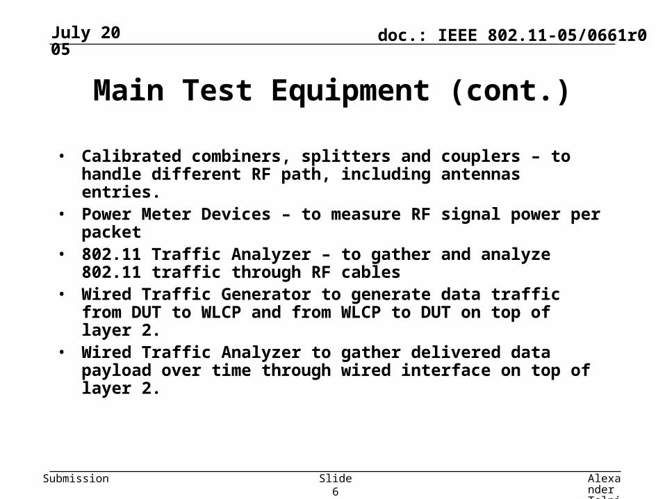
Main Test Equipment (cont.)
• Calibrated combiners, splitters and couplers – to handle different RF path, including antennas entries.
• Power Meter Devices – to measure RF signal power per packet• 802.11 Traffic Analyzer – to gather and analyze 802.11 traffic through RF
cables• Wired Traffic Generator to generate data traffic from DUT to WLCP
and from WLCP to DUT on top of layer 2.• Wired Traffic Analyzer to gather delivered data payload over time
through wired interface on top of layer 2.
July 2005
Alexander Tolpin, Intel
Slide 7
doc.: IEEE 802.11-05/0661r0
Submission
Main Test Equipment (cont.)
Test controller includes the following capabilities, likely automated and controlled by dedicated SW:
• The ability to control TX rates and TX power of WLCP and DUT• The ability to control power meters.• The ability to control attenuators• The ability to control Wired Traffic Analyzer• The ability to control Wired Traffic Generator.• The ability to control 802.11 Traffic Analyzer
July 2005
Alexander Tolpin, Intel
Slide 8
doc.: IEEE 802.11-05/0661r0
Submission
Calibration and isolation of the setup
• The setup shall be properly isolated from external interference and other unwanted signals.
• Prior to beginning the specific test, the test equipment shall be calibrated, taking into account losses due to cables, couplers, splitters etc.
• All test software shall be verified. • The test setup may be monitored during the test to
ensure that the test conditions do not change unintentionally.
July 2005
Alexander Tolpin, Intel
Slide 9
doc.: IEEE 802.11-05/0661r0
Submission
Typical conductive setup - superset
July 2005
Alexander Tolpin, Intel
Slide 10
doc.: IEEE 802.11-05/0661r0
Submission
Examples of setups
• Same test equipment may be used for many test setups depending on test objectives, for example:– Few DUTs may work together (bandwidth sharing test, fairness tests)– Few WLCPs may be used together, some of them, for example, to
generate internal interference signals (ACI, Roaming)– Different RF cables with different length controlled by attenuators may
simulate multi-path effects
• IEEE 802.11-05/0419r1 [7] briefly describes the following conductive setups– TPT vs Attenuation– Roaming– ACI – two configurations– Bandwidth sharing and fairness– Antenna Diversity
July 2005
Alexander Tolpin, Intel
Slide 11
doc.: IEEE 802.11-05/0661r0
Submission
TPT vs Attenuation – purpose• The primary metric is the average data payload successfully
transferred during 1 second from/to MAC SAP of DUT to/from MAC SAP of WLCP for specific attenuation of DUT.
• Attenuation corresponds to RX Power of the RF signal measured at the antenna connector of DUT
• Applicable for 802.11 wireless clients, both IBSS and BSS
• Provides the basic measure of the ability of DUT to transmit and receive frames without loss across the wireless interface in conductive environment.
• Correlates with end-user experiences of TPT vs range in a real life environment
• The additional secondary metrics may be measured concurrently: the retry rate and the non-acked rate.
July 2005
Alexander Tolpin, Intel
Slide 12
doc.: IEEE 802.11-05/0661r0
Submission
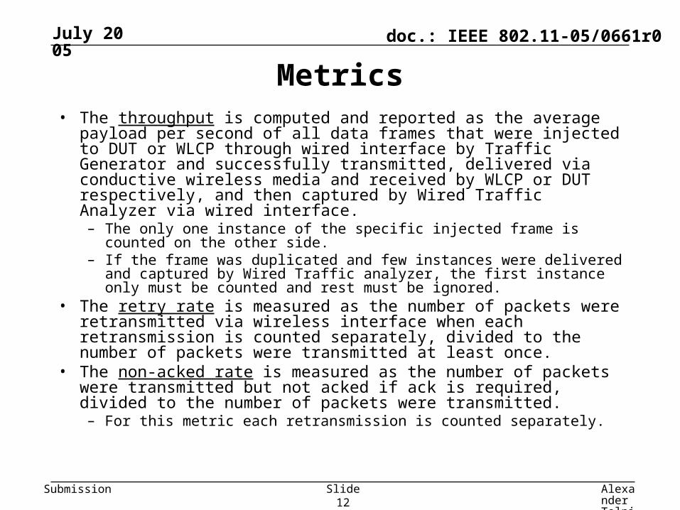
Metrics• The throughput is computed and reported as the average payload per
second of all data frames that were injected to DUT or WLCP through wired interface by Traffic Generator and successfully transmitted, delivered via conductive wireless media and received by WLCP or DUT respectively, and then captured by Wired Traffic Analyzer via wired interface. – The only one instance of the specific injected frame is counted on the
other side. – If the frame was duplicated and few instances were delivered and
captured by Wired Traffic analyzer, the first instance only must be counted and rest must be ignored.
• The retry rate is measured as the number of packets were retransmitted via wireless interface when each retransmission is counted separately, divided to the number of packets were transmitted at least once.
• The non-acked rate is measured as the number of packets were transmitted but not acked if ack is required, divided to the number of packets were transmitted. – For this metric each retransmission is counted separately.
July 2005
Alexander Tolpin, Intel
Slide 13
doc.: IEEE 802.11-05/0661r0
Submission
TPT vs. Attenuation conductive setup
July 2005
Alexander Tolpin, Intel
Slide 14
doc.: IEEE 802.11-05/0661r0
Submission
Procedure• Setup DUT to the initial configuration and associate with WLCP.
• Step 0: Set attenuation current_value=min_value.• Step 1:
– Test controller generates data traffic higher or equal to maximum theoretical throughput for specific frame sizes during required duration.
– The WLCP TX power is measured and recorded. – The traffic captured by the Wired Traffic Analyzer– TPT is measured and recorded. – The retry rate and non-ack rate are extracted by 802.11 Traffic Analyzer
and recorded. • Step 2: Set attenuation current_value+=step_value• Step 3: Repeat steps 1-2 until current_value>max_value
• Each attenuation value should be translated to DUT RX Power based on measured TX Power of WLCP, cables lost and attenuation values
• This is the secondary metric already discussed in [6].
• Based on the previously defined TPT vs Attenuation test.
• The purpose of this test is to determine the ability of DUT to select the TX rate that is the most efficient for current link condition.
• Applicable for 802.11 clients, both IBSS and BSS.• Allows discovering the root cause of TPT degradation.
July 2005
Alexander Tolpin, Intel
Slide 20
doc.: IEEE 802.11-05/0661r0
Submission
Metrics
• The TPT measured using automatic TX rate selection for specific attenuation (RX Power Level) is ActualTPT (RxPowerLevel).
• The maximum of TPT results achieved for the specific attenuation (RX Power) using fixed TX rates is BestTPT(RxPowerLevel).
• The Efficiency(RxPowerLevel) is the metric for a specific attenuation.
• The AverageEfficiency is the metric for the certain range of RX Power Level with n points of measurements.
)(
)()(
elRxPowerLevBestTP
elRxPowerLevActualTPelRxPowerLevEfficiency
n
elRxPowerLevEfficiencyiciencyAverageEff
)(
July 2005
Alexander Tolpin, Intel
Slide 21
doc.: IEEE 802.11-05/0661r0
Submission
Rate Adaptation conductive setup
July 2005
Alexander Tolpin, Intel
Slide 22
doc.: IEEE 802.11-05/0661r0
Submission
Procedure
• Setup DUT according to the initial configuration and associate with WLCP.
• Measure TPT vs. Attenuation using automatic rate selection, and record the ActualTPT
• Enforce DUT to transmit 802.11 data frames on the specific rate, measure TPT vs Attenuation and record TPT per fixed rate. – Repeat for all relevant fixed rates.
– Calculate the BestTPT (the maximum TPT achieved using different fixed rates) for each attenuation point
• Calculate Efficiency (RxPowerLevel) = ActualTPT/BestTPT for each attenuation point.
July 2005
Alexander Tolpin, Intel
Slide 23
doc.: IEEE 802.11-05/0661r0
Submission
Reporting
• The results can be summarized in the following table:
Attenuation (dB)
RX Power Level (dBm)
ActualTPT (MBps)
Fixed rate TPT (MBps) BestTPT (MBps)
Efficiency = ActualTPT/ BestTPT
TxRate#1 … TxRate#n
• The results should be reported as a table or a graph of Efficiency(RxPowerLevel)
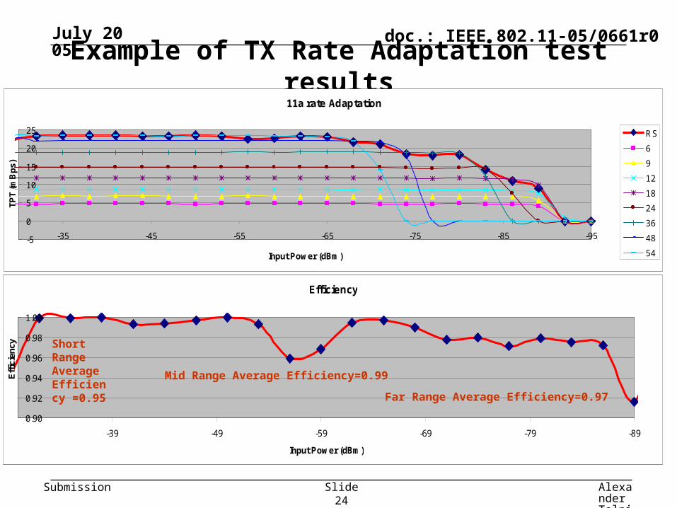
• The Average Efficiency should be calculated and reported for short range (above --35dBm), mid range (between -35dBm and -65dBm inclusive), and far range (below -65dBm till -85dBm)
July 2005
Alexander Tolpin, Intel
Slide 24
doc.: IEEE 802.11-05/0661r0
Submission
Example of TX Rate Adaptation test results11a rate Adaptation
-5
0
5
10
15
20
25
-95-85-75-65-55-45-35
Input Power (dBm)
TPT
(mB
ps)
RS
6
9
12
18
24
36
48
54
Efficiency
0.90
0.92
0.94
0.96
0.98
1.00
-89-79-69-59-49-39
Input Power (dBm)
Eff
icie
ncy
Short Range Average Efficiency =0.95
Mid Range Average Efficiency=0.99
Far Range Average Efficiency=0.97
July 2005
Alexander Tolpin, Intel
Slide 25
doc.: IEEE 802.11-05/0661r0
Submission
Antenna Diversity – purpose
• This is the secondary metric already discussed in [5]
• This test is based on the previously defined TPT vs Attenuation test.
• Applicable for 802.11 clients, both BSS and IBSS
• The purpose of this test is to determine how the changing of RF signal power for single MAIN and AUX antennas impacts TPT of DUT.
• The test provides the basic measure of an ability of DUT to select the optimal antenna when input RX power of each antenna is changing over time.
July 2005
Alexander Tolpin, Intel
Slide 26
doc.: IEEE 802.11-05/0661r0
Submission
Metric
• The required metric is the difference between TPT achieved when both antennas have same RX Power and when one antenna has less RX Power
• The expectation is that DUT selects the antenna with higher RX Power and TPT is not be impacted significantly.
July 2005
Alexander Tolpin, Intel
Slide 27
doc.: IEEE 802.11-05/0661r0
Submission
Antenna Diversity conductive setup
July 2005
Alexander Tolpin, Intel
Slide 28
doc.: IEEE 802.11-05/0661r0
Submission
Antenna Diversity measurement procedure
A = B
Dwell Time
Transition Time
Time
Power
A
B
A = B
Dwell Time
Transition Time
Time
Power
B
A
• The TPT is measured and recorded separately for each antenna combinations during dwell time and transition time
• Test parameters– Dwell time
– Transition time
– Minimum attenuation (maximum RF input power) for each antenna
– Maximum attenuation (minimum RF input power) for each antenna
July 2005
Alexander Tolpin, Intel
Slide 29
doc.: IEEE 802.11-05/0661r0
Submission
Reporting
• The results can be summarized in the following table:
Step Combinations of RX Power Time TPT measured Comments
0 A=B=maximum 0 N/A Initial setting
1 A=B=maximum Dwell Expect maximum TPT
2 A=maximum, B-> minimum Transition Expect a little TPT impact
3 A=maximum, B=minimum Dwell Expect antenna A selected
4 A=maximum, B->maximum Transition Expect TPT -> maximum
5 B=A=maximum Dwell Expect maximum TPT
6 A->minimum, B=maximum Transition Expect a little TPT impact
7 A=minimum, B=maximum Dwell Expect antenna B selected
8 A->maximum, B=maximum Transition Expect TPT -> maximum
July 2005
Alexander Tolpin, Intel
Slide 30
doc.: IEEE 802.11-05/0661r0
Submission
Conclusions• The conductive environment has been proposed• The proposal contains:
– Requirements for equipment– Requirements for test conditions– General test setup– Examples of specific setups for specific tests
• The three specific metrics have been proposed - Throughput vs. attenuation, TX rate adaptation and Antenna Diversity
• The proposal for each metric uses the template [2] and contains:– Purpose of the metric– Description of the metric– Description of the setup– Baseline, modifiers and test parameters– Procedure– Reporting results requirements
• Recommendation:– Recommend TGT to adopt the content of document 11-05/0660r0 into the
P802.11.2 draft.
July 2005
Alexander Tolpin, Intel
Slide 31
doc.: IEEE 802.11-05/0661r0
Submission
References
• [1] IEEE 802.11-1999.
• [2] IEEE 802.11-04/1540r1.Tom Alexander. Task Group T (WPP) Metrics Template.
• [3] IEEE 802.11-05/1641r1. Tom Alexander. Metrics Template Example
• [4] P802.11.2-D0.1. Draft Recommended Practice for the Evaluation of 802.11 Wireless Performance
• [5] IEEE 802.11-05/0194r0. Craig Warren. Performance Testing of Diversity for 802.11
• [6] IEEE 802.11-04/1466r1. Mike Wilhoyte. Some Concepts of Rate Management Testing
• [7] IEEE 802.11-05/419r1. Alexander Tolpin. Conductive Test Environment