September, 2019 doc.: IEEE 802.11-19/0856r6 IEEE P802.11 Wireless LANs Resolutions for some comments on 11md/D2.0 (LB236) Date: 2019-07-30 Author(s): Name Affiliation Address Phone email Mark RISON Samsung Cambridge Solution Centre SJH, CB4 0DS, U.K. +44 1223 434600 at samsung (a global commercial entity) I'm the letter emme then dot rison Submission page 1 Abstract This submission proposes resolutions for CIDs 2280, 2316, 2320, 2321, 2322, 2366, 2417, 2418, 2421, 2445, 2459, 2488, 2529, 2530, 2532, 2565, 2568, 2582, 2584, 2585, 2596, 2601, 2604, 2606, 2608, 2640 on 11md/D2.0. Green indicates material agreed to in the group, yellow material to be discussed, red material rejected by the group and cyan material not to be overlooked. The “Final” view should be selected in Word.
Transcript
September, 2019 doc.: IEEE 802.11-19/0856r6
IEEE P802.11Wireless LANs
Resolutions for some comments on 11md/D2.0 (LB236)
Date: 2019-07-30
Author(s):Name Affiliation Address Phone email
Mark RISON Samsung Cambridge Solution Centre SJH, CB4 0DS, U.K. +44 1223 434600
at samsung (a global commercial entity) I'm the letter emme
then dot rison
Submission page 1
AbstractThis submission proposes resolutions for CIDs 2280, 2316, 2320, 2321, 2322, 2366, 2417, 2418, 2421, 2445, 2459, 2488, 2529, 2530, 2532, 2565, 2568, 2582, 2584, 2585, 2596, 2601, 2604, 2606, 2608, 2640 on 11md/D2.0. Green indicates material agreed to in the group, yellow material to be discussed, red material rejected by the group and cyan material not to be overlooked. The “Final” view should be selected in Word.
"Ack Policy Indicator 0 is limited to at most one MU recipient perMU PPDU." -- this is not the meaning
Move this sentence to a table NOTE (since I understand these are normative, unlike running text NOTEs)
Discussion:
It is not clear what the commenter means by “this is not the meaning”.
The commenter is wrong to say that NOTEs in tables are normative. It’s only footnotes thereto (although only by implication through omission in footnote 17 (155.64 in D2.1)). See 13/0697:
7.5.8 Foot notes to a table are normative, but notes are informative.
However the cited sentence is misplaced, because (a) it only covers the Normal Ack ack policy, not the Implicit BAR ack policy and (b) there is already a more general statement about this (though it only covers VHT).
Proposed resolution:
REVISED
In 9.7.3 A-MPDU contents (D2.1/1654.60), add “or S1G MU PPDU” after “PPDU” in “A VHT MU PPDU does not carry more than one A-MPDU that contains one or more MPDUs soliciting an immediate response.”
In Table 9-535—Ack Policy Indicator(#1415) subfield in the Frame Control field for PV1 frames (D2.1/1660.26), delete “Ack Policy Indicator 0 is limited to at most one MU recipient per MU PPDU.”
Note to the commenter: it is not the case that NOTEs in tables are normative. It’s only footnotes thereto (although only by implication through omission in footnote 17 (155.64 in D2.1)) that are. See 13/0697:
7.5.8 Foot notes to a table are normative, but notes are informative.
9.7.3 says (implicitly for all STAs) " All QoS Data frames within an A-MPDU that have a TID for which an HT-immediate block ack agreement exists have the same value for theAck Policy Indicator(#1415) subfield of the QoS Control field." But 10.15 says (for DMG STAs) " All QoS Data frames within A-MPDUs within an A-PPDU shall have the same ack policy." These are not the same (the ack policy is the combination of the Ack Policy Indicator field and other things)
Change 9.7.4 to say " All QoS Data frames within A-MPDUs within an A-PPDU shall have the same value for the Ack Policy Indicator subfield."
CID 2322Mark RISON10.151781.29
9.7.3 says (implicitly for all STAs) " All QoS Data frames within an A-MPDU that have a TID for which an HT-immediate block ack agreement exists have the same value for theAck Policy Indicator(#1415) subfield of the QoS Control field." But 10.15 says (for DMG STAs) " All QoS Data frames within A-MPDUs within an A-PPDU shall have the same ack policy." These are not the same (the ack policy is the combination of the Ack Policy Indicator field and other things)
Delete the cited sentence in 10.15 (since the 9.7.3 sentence covers it (presuming nothing other than HT-immediate is allowed for DMG))
Discussion:
9.7.3 A-MPDU contents does indeed say (D2.1/1654.4):
All QoS Data frames within an A-MPDU that have a TID for which an HT-immediate block ack agreement exists have the same value for the Ack Policy Indicator(#1415) subfield of the QoS Control field.
10.15 DMG A-PPDU operation does indeed say (D2.1/1781.29):
All QoS Data frames within A-MPDUs within an A-PPDU shall have the same ack policy(#1415).
The ack policy is the combination of the Ack Policy Indicator subfield and other information (e.g. whether the MPDU is a non-A-MPDU frame). Also, the second statement is not restricted to MPDUs sent under HT-immediate BA. So the second statement is wider than the first (i.e. QoS Data frames in DMG A-PPDUs are more constrained than other QoS Data frames).
Proposed resolution:
REJECTED
The ack policy is the combination of the Ack Policy Indicator subfield and other information (e.g. whether the MPDU is a non-A-MPDU frame). Also, the second statement is not restricted to MPDUs sent under HT-immediate BA. So the second statement is wider than the first (i.e. QoS Data frames in DMG A-PPDUs are apparently more constrained than other QoS Data frames).
"Bits in QoS Control field" in Table 9-13---Ack policy should refer to Ack Policy Indicator subfield (cf. Table 9-535---Ack Policy Indicator(#1415) subfield in the Frame Control field for PV1 frames(11ah))
Change the cited heading cell to "Ack Policy Indicator subfield" and renumber the bits below from 5, 6 to 0, 1 respectively
Discussion:
Best practice is for subfield bit definitions to be stand-alone, not dependent on position within the parent field.Multiple subfields of the QoS Control field violate this:
Proposed resolution:
REVISED
In Table 9-12—TID subfield (D2.1/790.11), change “Allowed values in bits 0–3 (TID subfield)” to “Allowed values”.
In the header row of Table 9-13—Ack policy (D2.1/791.8), change “Bits in QoS Control field” to “Ack Policy Indicator subfield” and change “Bit 5” and “Bit 6” to “Bit 0” and “Bit 1” respectively, as proposed by the commenter.
In Figure 9-10—Buffered AC subfield (D2.1/795.17), change the top row from “B10 B11 B12 B13” to “B0 B1 B2 B3”.
"The MPDUExchangeTime equals the time required to transmit the MPDU sequence." -- it is not clear what an MPDU sequence is
Change the cited text at the referenced location to "The MPDUExchangeTime is the duration of the TXOP."
Discussion:
The term “MPDU sequence” is not defined and is not used anywhere else.
Since this is about admission control, the intent must be to account for the time that the TXOP holder has ownership of the medium, since during this time other STAs cannot make use of the medium. Describing it as “the duration of the TXOP” captures this, and is flexible enough to account for corner cases like TXOP truncation.
Proposed resolution:
REVISED
At 1832.15 in D2.2, change:
b) After each successful or unsuccessful MPDU (re)transmission attempt,
to:
b) After each successful or unsuccessful frame exchange sequence,
At 1832.19 in D2.2, change:
The MPDUExchangeTime equals the time required to transmit the MPDU sequence.
to:
The MPDUExchangeTime is the duration of the frame exchange sequence.
"Commit message" -- no such message Prepend "SAE " to the cited text throughout the referenced subclause (7x)
Discussion:
The only places where “Commit message” appears without “SAE” preceding it are the 7 locations identified, and Figure 4-34—Example using SAE authentication. Here is the subclause in question:
12.4.7.4 Encoding and decoding of SAE Commit messages
An SAE Commit message shall be encoded as an Authentication frame with an Authentication AlgorithmNumber field set to 3, a Transaction Sequence Number of 1 and a Status Code of SUCCESS Status codesnot equal to SUCCESS indicate a rejection of a peer’s SAE Commit message and are described in 12.4.7.6(Status codes).
An SAE Commit message shall consist of a Finite Cyclic Group field (9.4.1.42 (Finite Cyclic Group field))indicating a group, a Scalar field (9.4.1.39 (Scalar field)) containing the scalar, and an FFE field containingthe element (9.4.1.40 (Finite field element (FFE) field)). If the SAE Commit message is in response to anAnti-Clogging Token field(#2534) request (see 12.4.7.6 (Status codes)), the Anti-Clogging Tokenfield(#2534) is present (see 9.4.1.38 (Anti-Clogging Token field)). If a password identifier is used ingeneration of the password element (PWE) the Password identifier element shall be present and theidentifier shall be encoded as a UTF-8 string in the Identifier portion of the element (see 9.4.2.216(Password identifier element(M41))).(M41)
When transmitting an SAE Commit message, the scalar and element shall be converted to octet strings andplaced in the Scalar field and FFE field, respectively. The scalar shall be treated as an integer and convertedinto an octet string of length m such that 28m > r, where r is the order of the group, according to 12.4.7.2.2(Integer to octet string conversion), and the element shall be converted into (an) octet string(s) according to12.4.7.2.4 (Element to octet string conversion). When receiving an SAE Commit message the componentoctet strings in the Scalar field and Element field shall be converted into a scalar and element, respectively,according to 12.4.7.2.3 (Octet string to integer conversion) and 12.4.7.2.5 (Octet string to elementconversion), respectively.
(M73)NOTE—Anti-clogging tokens, password identifiers, and vendor specific additions may be optionally present in areceived Commit message. Since the size of the Scalar field and Element field are determined by the Group field, anyanti-clogging token present will be of a size determined by the recipient, and the Password Identifier is an element witha well-defined prefix, the Commit message can be unambiguously parsed using the following technique:a) Compute the following values:— Base length is the sum of the length of the Group field, the length of the Scalar field, and the length of theElement field— Token length is the size of a requested anti-clogging token b) If the length of the Commit message equals the base length then there is no token, no password identifier, andno vendor specific additions;c) If the length of the Commit message is greater than the base length but less than the sum of the base length andtoken length and a Password Identifier element follows the Element field, then there is a password identifierand no token. If a Password Identifier element does not follow the Element field or the length of the Commitmessage indicates there are additional octets following the Password Identifier element, then there are vendorspecific additions.d) If the length of the Commit message is greater than the sum of the base length and the token length and a Pass-word Identifier element follows the Element field, then there is a password identifier and a token. If a PasswordIdentifier element does not follow the Element field or the length of the Commit message indicates there are
Submission page 6
September, 2019 doc.: IEEE 802.11-19/0856r6
additional octets following the Password Identifier element, then there are vendor specific additions.
Proposed resolution:
REVISED
Prepend “SAE ” to “Commit message” throughout the NOTE in Subclause 12.4.7.4 (7x), as proposed by the commenter (other instances in the rest of the subclause appear to have been fixed by D2.1).
In Figure 4-34—Example using SAE authentication (D2.1/289.24), change “Commit Message” to “SAE Commit message” (2x) and “Confirm Message” to “SAE Confirm message” (2x).
"Element field" -- no such field Change "Element field" to "FFE field" throughout the referenced subclause. In Table 9-43 change "Element is present" to "An FFE field is present", add "A " at the start of the 1st, 4th and 5th sentences of the bottom rightmost cell on p.875, add "An " at the start of the 4th, and add "field " before "is present" for the 1st, 3rd and 4th sentences
Discussion:
There is no such field as the “Element field” (good thing, as this would be mega-confusing!). The field is called the FFE field:
So all of the following should refer to the FFE field:
12.4.7.4 Encoding and decoding of SAE Commit messages
An SAE Commit message shall be encoded as an Authentication frame with an Authentication AlgorithmNumber field set to 3, a Transaction Sequence Number of 1 and a Status Code of SUCCESS Status codesnot equal to SUCCESS indicate a rejection of a peer’s SAE Commit message and are described in 12.4.7.6(Status codes).
An SAE Commit message shall consist of a Finite Cyclic Group field (9.4.1.42 (Finite Cyclic Group field))indicating a group, a Scalar field (9.4.1.39 (Scalar field)) containing the scalar, and an FFE field containingthe element (9.4.1.40 (Finite field element (FFE) field)). If the SAE Commit message is in response to anAnti-Clogging Token field(#2534) request (see 12.4.7.6 (Status codes)), the Anti-Clogging Tokenfield(#2534) is present (see 9.4.1.38 (Anti-Clogging Token field)). If a password identifier is used ingeneration of the password element (PWE) the Password identifier element shall be present and theidentifier shall be encoded as a UTF-8 string in the Identifier portion of the element (see 9.4.2.216(Password identifier element(M41))).(M41)
When transmitting an SAE Commit message, the scalar and element shall be converted to octet strings andplaced in the Scalar field and FFE field, respectively. The scalar shall be treated as an integer and convertedinto an octet string of length m such that 28m > r, where r is the order of the group, according to 12.4.7.2.2(Integer to octet string conversion), and the element shall be converted into (an) octet string(s) according to12.4.7.2.4 (Element to octet string conversion). When receiving an SAE Commit message the componentoctet strings in the Scalar field and Element field shall be converted into a scalar and element, respectively,according to 12.4.7.2.3 (Octet string to integer conversion) and 12.4.7.2.5 (Octet string to element
Submission page 8
September, 2019 doc.: IEEE 802.11-19/0856r6
conversion), respectively.
(M73)NOTE—Anti-clogging tokens, password identifiers, and vendor specific additions may be optionally present in areceived Commit message. Since the size of the Scalar field and Element field are determined by the Group field, anyanti-clogging token present will be of a size determined by the recipient, and the Password Identifier is an element witha well-defined prefix, the Commit message can be unambiguously parsed using the following technique:a) Compute the following values:— Base length is the sum of the length of the Group field, the length of the Scalar field, and the length of theElement field— Token length is the size of a requested anti-clogging token b) If the length of the Commit message equals the base length then there is no token, no password identifier, andno vendor specific additions;c) If the length of the Commit message is greater than the base length but less than the sum of the base length andtoken length and a Password Identifier element follows the Element field, then there is a password identifierand no token. If a Password Identifier element does not follow the Element field or the length of the Commitmessage indicates there are additional octets following the Password Identifier element, then there are vendorspecific additions.d) If the length of the Commit message is greater than the sum of the base length and the token length and a Pass-word Identifier element follows the Element field, then there is a password identifier and a token. If a PasswordIdentifier element does not follow the Element field or the length of the Commit message indicates there areadditional octets following the Password Identifier element, then there are vendor specific additions.
Ditto in Table 9-43—Presence of fields and elements in Authentication frames:
(#2471) Finite field element is present if the Status Code field is zero.
The other changes proposed to the SAE 1 row are valid too, but should be “The” and should be applied in other places too. There are various other editorial issues.
Proposed changes:
Change "Element field" to "FFE field" throughout Subclause 12.4.7.4, as proposed by the commenter (D2.2/2550.32 seems to be the only instance; others have been addressed already through other comments).
In Table 9-43—Presence of fields and elements in Authentication frames, change the rightmost cell of the SAE 1 and 2 rows (D2.2/878.9) as follows:
(Ed)The Scalar field(#2531) is present if the Status Code field is zero.(#2471)(Ed)The FFE field(#2531) is present if the Status Code field is zero.(Ed)The Anti-Clogging Token field(#2534) is present if statusthe Status Code field is 76 or if the Authentication frame is in response to a previous rejection with the Status Code field equal to 76.(Ed)The Finite Cyclic Group field(#2531) is present if the Status Code field is zero, 76, or 77.(M104)(M41)(Ed)The Password Identifier element is optionally present if the Status Code field is zero or 123(Ed).
The Send-Confirm field is present.<newline>The Confirm field is present.
In Table 9-43—Presence of fields and elements in Authentication frames, change “if Status Code” to “if the Status Code” (18 instances).
Proposed resolution:
REVISED
Submission page 9
September, 2019 doc.: IEEE 802.11-19/0856r6
Make the changes shown under “Proposed changes” for CID 2530 in <this document>, which address the issues raised by the commenter.
"Group field" -- no such field Change "Group field" to "Finite Cyclic Group field" throughout the referenced subclause
Discussion:
The field containing the finite cyclic group should be referred to as the Finite Cyclic Group field throughout.
Proposed resolution:
REVISED
In 9.6.7.24 Public Key frame (D2.1/1520.21), change “Group” to “Finite Cyclic Group” throughout (2 instances). In 12.11.2 AP PeerKey protocol (D2.1/2671.6), change “Group field” and “group field” to “Finite Cyclic Group field” (3 instances of first and 2 instances of second).
In the NOTE in 12.4.7.4 Encoding and decoding of SAE Commit messages (D2.1/2539.7), change “Group” to “Finite Cyclic Group” (2 instances), as proposed by the commenter.
"{Key Data} is a sequence of zero or more elements and KDEs" -- so it's not clear how you determine whether something is a VS element or a KDE
Change the cited text at the referenced location to "{Key Data} is a sequence of zero or more elements (that are not Vendor-Specifc elements) and KDEs"
Discussion:
Actually, there is no way to distinguish, from the encoding, a vendor-specific KDE from a vendor-specific element.
Proposed resolution:
REVISED
In 12.7.2 EAPOL-Key frames j) (D2.1/2620.7), delete “Elements sent in the Key Data field include the Element ID and Length subfields.”
In 12.7.2 EAPOL-Key frames j) (D2.1/2620.7), change “zero or more key data cryptographic encapsulation(s) (KDEs) (such as GTK(s) or PMKID(s))” to “zero or more key data encapsulation(s) (KDEs) (such as the GTK KDE or PMKID KDE(s))”.
In 12.7.2 EAPOL-Key frames, after “The Type field shall be set to 0xdd. The Length field specifies the number of octets in the OUI, Data Type, and Data fields. The OUI field contains either an OUI or CID. The order of the OUI field is described in 9.2.2 (Conventions).” (D2.1/2620.22), insert a “NOTE—The KDE format is a subset of the Vendor Specific element format (see 9.4.2.25). It is generally not possible to distinguish, from the format, a Vendor Specific element and a vendor specific KDE.”
In 12.5.4.4 BIP replay protection (D2.1/2572.63), change “IGTK key data encapsulation (KDE)” to “IGTK KDE”.
Ack behavior depends on "Where either the originator or the addressed recipient does not support fragment BA procedure". This is bad form, asking a RXr to know the originator's capabilities to know how to ACK something. Should be replaced with signalling/state known immediately by the RXr. Also, the cited sentence doesn't make sense (it starts with "Where", but doesn't have any subjunctive), and the following sentence "Otherwise" isn't clear (otherwise to what?). Lastly, is it reasonable to believe a RXr will be able to determine if a frame contains a fragment quickly enough to decide whether to Ack?
1) Change this sentence (and the one above with the opposite case) to reference information known by the RXr.2) Fix the two sentences' (second "Where", and following "Otherwise") wording.3) Address whether a RXr will be able to determine if a frame contains a fragment quickly enough to decide whether to Ack.
Discussion:
The editorial point (2) is valid. The technical points (1 and 3) are valid in theory too (especially 1, since it involves looking up by MAC address), but in practice since fragment BA is only allowed for S1G STAs and SIFS is 160 µs for S1G BSSes, there’s enough time to do the requisite processing.
Proposed changes:
Change Table 9-535—Ack Policy Indicator(#1415) subfield in the Frame Control field for PV1 frames(11ah) as follows:
(M86)Where the frame contains a fragment and both the originator and the addressed recipient support the fragment BA procedure:The addressed recipient returns an NDP BlockAck or BAT frame after a SIFS, according to the procedures defined in 10.3.2.12 (Fragment BA procedure(11ah)) and 10.48.2 (TWT acknowledgment procedure). (#1415)(#233)Where the frame does not contain a fragment, or either the originator or the addressed recipient does not support the fragment BA procedureOtherwise:The addressed recipient returns an Ack, TACK or STACK frame after a short interframe space (SIFS) period, according to the procedures defined in 10.3.2.11 (Acknowledgment procedure) and 10.48.2 (TWT acknowledgment procedure). (M86)
Change Table 9-13—Ack policy(#1415) as follows:
(M86)Where the frame contains a fragment whereandboth the originator and the addressed recipientsupport the fragment BA procedure:The addressed recipient returns an NDP BlockAckor BAT frame after a SIFS, according to theprocedures defined in 10.3.2.12 (Fragment BAprocedure(11ah)) and 10.48.2 (TWTacknowledgment procedure).(#1415)(#233)Where the frame does not contain a
Submission page 13
September, 2019 doc.: IEEE 802.11-19/0856r6
fragment, or either the originator or the addressedrecipient does not support the fragment BAprocedure. Otherwise:The addressed recipient returns an Ack,STACK(M86), or QoS +CF-Ack frame after a shortinterframe space (SIFS) period, according to theprocedures defined in 10.3.2.11 (Acknowledgmentprocedure), (M86)10.48.2 (TWT acknowledgmentprocedure), and 10.24.3.5 (HCCA transfer rules). Anon-DMG STA uses this ack policy for individuallyaddressed QoS Null (no data) frames.(M86)
Proposed resolution:
REVISED
In Table 9-535—Ack Policy Indicator(#1415) subfield in the Frame Control field for PV1 frames(11ah), change “Where the frame does not contain a fragment, or either the originator or the addressed recipient does not support the fragment BA procedure:” (D2.1/1660.18) to “Otherwise:”. In Table 9-13—Ack policy(#1415), delete “Where the frame does not contain a fragment, or either the originator or the addressed recipient does not support the fragment BA procedure.” (D2.1/791.19), insert a comma after “The addressed recipient returns an NDP BlockAck or BAT frame after a SIFS” and change “Where the frame contains a fragment where both the originator and the addressed recipient support the fragment BA procedure:” (D2.1/791.10) to “Where the frame contains a fragment and both the originator and the addressed recipient support the fragment BA procedure:”.
This addresses editorial point 2. Regarding technical points 1 and 3, these are rejected because: Fragment BA is only used in S1G BSSes (10.3.2.12: “Non-S1G STAs shall not use the fragment BA
procedure described in this subclause.”) aSIFSTime in S1G BSSes is 160 µs (Table 23-37—S1G PHY characteristics) This should be sufficient time for the receiver to check the originator capabilities (looking up the TA) and
examine the MAC header to determine whether a fragment is present (More Fragments set or Fragment Number non-zero)
If this isn’t the case the receiver can simply not declare support for fragment BA (see Fragment BA Support subfield in S1G Capabilities Information field in S1G Capabilities element and dot11FragmentBAOptionImplemented)
"member of an IBSS" should canonically be "IBSS STA". Ditto for MBSS
Change "member of an IBSS" to "IBSS STA" throughout, changing any preceding "a" to "an". Change "member of an MBSS" to "MBSS STA" throughout, changing any preceding "a" to "an"
Discussion:
“member of an IBSS” appears 20 times in D2.1; “IBSS STA” appears 75 times. The term “IBSS STA” is not, however, defined.
“member of a mesh BSS”/”member of an MBSS” appears 10/11 times; “MBSS STA” does not appear but “mesh STA” appears over 2000 times. A “mesh STA” is defined as “A quality-of-service (QoS) STA that implements the mesh facility.”
Proposed resolution:
REVISED
Note to the commenter: “member of a mesh BSS/MBSS” is not the same as “MBSS STA”, since the latter is defined as a STA that implements mesh, not a STA that is actually doing mesh. (Whether this is a good idea is a separate issue…)
In 3.1 add a definition “independent basic service set (IBSS) station (STA): A STA that has started or joined an IBSS.”
Change “a STA that is a member of an IBSS” to “an IBSS STA” in 5.2.5.2 Semantics of the service primitive.Change “STA that is a member of an IBSS” to “IBSS STA” in Table 9-31—STA Info subfields and 10.37.5.2 Rules for VHT sounding protocol sequences (2x).Change “a member of an IBSS” to “an IBSS STA” in 9.3.2.1.2 Address and BSSID fields; 10.28.2 Protection mechanism for non-ERP receivers (3x); 11.5.2.2 Procedure at the originator; 11.15.1 Rules for operation in 20/40 MHz BSS; 11.15.2 Basic 20/40 MHz BSS functionality; 11.39.4 Channel switching methods for a VHT BSS (2x), C.3 for dot11QMFActivated (2x).Change “operating as a member of an IBSS” to “an IBSS STA” in 10.3.9 Determination of PLME aCWmin characteristics.Change “sent by a STA that is a member of an IBSS to a STA or STAs that are members of an IBSS” to “sent by an IBSS STA to one or more IBSS STAs” in 10.22 Group ID, partial AID, Uplink Indication, and COLOR in S1G PPDUs.Change “member of an IBSS” to “IBSS STA” in 10.23.5 Operation with coverage classes.Change “A STA that is a member of an IBSS” to “An IBSS STA” in 10.28.3.1 General (under 10.28.3 Protection mechanisms for transmissions of HT PPDUs).Change “members of an IBSS” to “IBSS STAs” in 9.3.3.1 Format of Management frames.
Submission page 15
Mark Rison, 01/05/19,
Hm, so a STA that implements mesh but is currently operating in an IBSS or infrastructure BSS or PBSS is a “mesh STA”? I suspect that’s not how “mesh STA” is actually used; rather, it’s actually used to mean “is starting/joining or has started/joined an MBSS”. However, 4.3.21.4 says “Accordingly, a mesh STA is not a member of an IBSS or an infrastructure BSS.”, which prima facie contradicts the definition
Duplication: "; but, if it does not support that procedure and dot11RejectUnadmittedTraffic is false or not present, it shall use EDCA parameters of a lower priority AC, as indicated in Table 10-1 (UP-to-AC mappings), that does not require admission control. When a STA uses the EDCA parameters of a lower-priority AC for this purpose, it affects only the EDCA parameters used for channel access, i.e., it has no effect on the contents of the transmitted frame" and "If dot11RejectUnadmittedTraffic is false, a STA may send data without admission control for an AC that mandates admission control by using the EDCA parameters that correspond to a lower priority AC that does not require admission control. When a STA uses a lower priority AC for this purpose, the lower priority AC affects only the EDCA parameters used for channel access, i.e., it has no effect on the contents of the transmitted frame." Actually not duplication but contradiction since the first is shall and the second is may
Delete the first of the two cited blocks of text
Discussion:
Start of 10.24.4.2.1 (bit in yellow is proposed for deletion):
A non-AP STA may support admission control procedures in 10.24.4.2.3 (Procedure at non-AP STAs) to send frames in the AC where admission control is mandated; but, if it does not support that procedure and dot11RejectUnadmittedTraffic is false or not present, it shall use EDCA parameters of a lower priority AC, as indicated in Table 10-1 (UP-to-AC mappings), that does not require admission control. When a STA uses the EDCA parameters of a (#149)lower-priority AC for this purpose, it affects only the EDCA parameters used for channel access, i.e., it has no effect on the contents of the transmitted frame. An AP shall support admission control procedures, at least to the minimal extent of advertising that admission is not mandatory on its ACs.
Middle of next para (bit in yellow is proposed to be kept):
The STA may transmit unadmitted traffic for the ACs for which the AP does not require admission control. If dot11RejectUnadmittedTraffic is false, a STA may send data without admission control for an AC that mandates admission control by using the EDCA parameters that correspond to a lower priority AC that does not require admission control. When a STA uses a lower priority AC for this purpose, the lower priority AC affects only the EDCA parameters used for channel access, i.e., it has no effect on the contents of the transmitted frame.
Note also the definition of the Reject Unadmitted Frame extended capability (sic):
When dot11RejectUnadmittedTraffic is true, the Reject Unadmitted Frame bit is set to 1 to indicate that the STA rejects MA-UNITDATA.request primitives for frames belonging to an unadmitted TS.
Submission page 16
Mark Rison, 01/05/19,
Should this be strengthened to “If dot11RejectUnadmittedTraffic is true, a STA shall not send data without admission control for an AC that mandates admission control.”? Otherwise there’s no clear normative behavioural requirement if dot11RejectUnadmittedTraffic is true, except for a row in a Clause 9 table (see below) and a vague statement in the description of MA-UNITDATA-STATUS.indication and of dot11RejectUnadmittedTraffic
September, 2019 doc.: IEEE 802.11-19/0856r6
When dot11RejectUnadmittedTraffic is false, the Reject Unadmitted Frame bit is set to 0 to indicate that the STA is not required to reject MA-UNITDATA.request primitives for frames belonging to an unadmitted TS.
This does seem like duplication, and as regards the contradiction it seems the intent is to allow but not require a STA to downgrade if dot11RejectUnadmittedTraffic is false.
Proposed changes:
Change 10.24.4.2.1 (D2.2/1830.43) as follows:
An AP shall support admission control procedures, at least to the minimal extent of advertising that admission is not mandatory on its ACs. The AP uses the ACM (admission control mandatory) subfields advertised in the EDCA Parameter Set element to indicate whether admission control is required for each of the ACs. All ACs with priority higher than that of an AC with an ACM flag equal to 1 should have the ACM flag set to 1. While the CWmin, CWmax, AIFS, and TXOP limit parameters may be adjusted over time by the AP, the ACM bit shall be static for the duration of the lifetime of the BSS. [this text just moved from below with paragraphing modifications]
A non-AP STA may send frames in an AC where admission control is not mandated.
A non-AP STA may support the admission control procedures in 10.24.4.2.3 (Procedure at non-AP STAs) to send frames in thean AC where admission control is mandated; but, i. If it does not support that procedure or admission was denied, and both of the following apply:and
dot11RejectUnadmittedTraffic is false or not present, t here is it shall use EDCA parameters of a lower priority AC, as indicated in (see Table 10-1 (UP-
to-AC mappings)), that does not require admission controlthen it may send such frames using the EDCA parameters of that lower priority AC for channel access; . When a STA uses the EDCA parameters of a (#149)(#2443)lower priority AC for this purpose, it affects only the EDCA parameters used for channel access, i.e., it has no effect on the contents of the transmitted frames are unaffected. Otherwise, it shall not send such frames.
An AP shall support admission control procedures, at least to the minimal extent of advertising that admission is not mandatory on its ACs. <remove the para break> The AP uses the ACM (admission control mandatory) subfields advertised in the EDCA Parameter Set element to indicate whether admission control is required for each of the ACs. While the CWmin, CWmax, AIFS, and TXOP limit parameters may be adjusted over time by the AP, the ACM bit shall be static for the duration of the lifetime of the BSS. <para break>
A STA shall transmit an ADDTS Request frame to the HC in order to request admission of traffic in any direction (i.e., uplink, downlink, direct, or bidirectional) employing an AC that requires admission control. The ADDTS Request frame shall contain the UP associated with the traffic and shall indicate EDCA as the access policy. The AP shall associate the received UP of the ADDTS Request frame with the appropriate AC per the UP-to-AC mappings described in 10.2.3.2 (HCF contention based channel access (EDCA)). The STA may transmit unadmitted traffic for the ACs for which the AP does not require admission control. If dot11RejectUnadmittedTraffic is false, a STA may send data without admission control for an AC that mandates admission control by using the EDCA parameters that correspond to a lower priority AC that does not require admission control. When a STA uses a lower priority AC for this purpose, the lower priority AC affects only the EDCA parameters used for channel access, i.e., it has no effect on the contents of the transmitted frame. All ACs with priority higher than that of an AC with an ACM flag equal to 1 should have the ACM flag set to 1. <para break>
The HC contained within an AP when dot11SSPNInterfaceActivated is true shall admit a non-AP STA’s request based on dot11NonAPStationAuthAccessCategories stored in that non-AP STA’s
Submission page 17
September, 2019 doc.: IEEE 802.11-19/0856r6
dot11InterworkingEntry, which is part of the dot11InterworkingTable. The dot11InterworkingEntry specifies the EDCA access classes and throughput limitations on each access class for which a non-AP STA is permitted to transmit.
Proposed resolution:
REVISED
Make the changes shown under “Proposed changes” for CID 2596 in <this document>, which make the change suggested by the commenter with additional editorial clarifications.
Re CID 1468: need to be clearer that the ED thresholds are based on declaring busy *if* a PPDU of a given type with energy above a certain threshold is present, not based on detecting a PPDU of a given type and *then* checking the energy is above the corresponding threshold
As it says in the comment
Discussion:
CID 1468 was:
CommentThe HT rules for CCA as they pertain to non-HT transmissions are not clear. The issue is that if you don't know you're dealing with a non-HT transmission (which you don't know unless you successfully pick up the preamble) you don't know you have to apply the rules ("CCA sensitivity requirements for non-HT PPDUs")
Proposed changeMake it clear that the energy detect rules (not the CCA-ED rules, which are something different) from 18 and 19 apply even if you can't work out what type of PPDU/energy you're dealing with (these are "detect a medium busy condition within 4 us of any signal with a
received energy that is 20 dB above the minimum modulation and coding rate sensitivity" for 2.4 GHz and -- hm, 19.4.6 has no energy detect requirement, that's in 19.3.4 ... but there's no just energy detect requirement there too. Does this mean HT has no just energy detect requirements (again, not talking of CCA-ED here) in the 5 GHz band?
ResolutionREJECTED (EDITOR: 2018-07-16 17:24:04Z) - The draft is already clear that pure energy detect is required for HT STAs, in both the 2.4 and 5 GHz bands: see 19.3.19.5.3. The draft already contains text matching the proposed change, in 19.3.19.5.3.
The issue is that we have e.g. the following in Clause 19:
19.3.19.5.3 CCA sensitivity for non-HT PPDUs
CCA sensitivity requirements for non-HT PPDUs in the primary channel are described in 17.3.10.6 (CCArequirements) and 18.4.6 (CCA performance).
19.3.19.5.4 CCA sensitivity in 20 MHz
For an HT STA with the operating channel width equal to 20 MHz, the start of a valid 20 MHz HT signal at a receive level greater than or equal to the minimum modulation and coding rate sensitivity of –82 dBm shall cause the PHY to set PHY-CCA.indication(BUSY) with a probability > 90% within 4 µs. The
Submission page 19
September, 2019 doc.: IEEE 802.11-19/0856r6
receiver shall indicate a channel busy condition for any signal 20 dB or more above the minimum modulation and coding rate sensitivity (–82 + 20 = –62 dBm) in the 20 MHz channel.An HT STA that does not support the reception of HT_GF format PPDUs shall indicate a channel busycondition (PHY-CCA.indication(BUSY)) for any valid HT_GF signal in the 20 MHz channel at a receivelevel greater than or equal to –72 dBm.
Consider the highlighted sentences. One interpretation is “if you receive a non-HT PPDU, use the 17.3.10.6 requirements for CCA; if you receive an HT PPDU use the requirements here”. Another interpretation is “if presented with a non-HT PPDU (whether or not you actually receive it, i.e. there are no uncorrectable errors), you shall meet the 17.3.10.6 requirements for CCA; if presented with an HT PPDU, you shall meet the requirements here”.
The latter is the intended interpretation. However, the “valid” suggests the former, since it suggests you need to receive the HT header, at least, to determine whether it is valid. And in any case the standard is concerned with conformant implementations, so we need not concern ourselves with “invalid” transmissions (same reason we don’t/shouldn’t say “successfully receive”).
Proposed resolution:
REVISED
In the table in 6.5.4.3 When generated (in the aCCATime row), in 17.3.10.6 CCA requirements, in 19.3.19.5.4 CCA sensitivity in 20 MHz, in 19.3.19.5.5 CCA sensitivity in 40 MHz (2x), in 20.4.4.2.2 CCA, in 20.5.4.2.2 CCA, in 24.4.4.2.2 CCA, in 24.5.4.2.2 CCA, 25.4.6.2.2 CCA, 25.5.7.2.2 CCA, 25.6.9.3.2 CCA: change “a valid” to “a” or “an”, as appropriate for the starting sound of the following word. In 18.4.6 CCA performance change “a valid ERP-OFDM signal or valid ERP-DSSS/CCK sync symbols” to “an ERP-OFDM signal or ERP-DSSS/CCK sync symbols”; “a valid signal” to “an ERP-OFDM signal or ERP-DSSS/CCK sync symbols”.
10.3.4.3 (Backoff procedure for DCF) says (paragraph 5) [context:backoff suspended when medium busy]: "The medium shall be determined tobe idle for the duration of a DIFS --->*or EIFS*<---- as appropriate... before the backoff procedure is allowed to resume".
This conflicts with a reading of the lettered paragraphs in 10.22.2.4,which determine the corresponding rules for EDCA. Note in particularthat the only mention of EIFS is in b), which is therefore crucial. The prologue to the lettered items says "EDCAFoperations shall be performed at slot boundaries, defined as follows onthe primary channel, for each EDCAF:".
b) Following EIFS - DIFS + AIFSN[AC] x aSlotTime + aSIFSTime - aRxTxTurnaroundTime of idle medium after the last indicated busy medium as determined by the physical CS mechanism that was the result of a (11ah)non-S1G frame reception that has resulted in FCS error, or (11ah)of a frame reception that has resulted in PHY-RXEND.indication (RXERROR) primitive where the value of RXERROR is not NoError.
Note in particular that EIFS here is applied only for busy medium thatwas the result of the error itself.
So it seems that when there is later busy medium, and hence thebackoff is suspended in the sense of 10.3.4.3, the catch-all item e) forwhat to do following busy medium applies. This makes no mention ofusing EIFS, so the medium only has to be clear for the standard formulainvolving AIFS at this point.
FWIW, the EDCA version probably makes more sense. The point of EIFS isto clear out a single possible bad frame from consideration. Repeateduse of EIFS after that has happened doesn't
Delete " or EIFS" in "The backoff counter is next decremented after the medium has been determined to beidle for the duration of a DIFS or EIFS, as appropriate" in 10.4.3.4
Submission page 21
September, 2019 doc.: IEEE 802.11-19/0856r6
seem useful.
[This was rejected in CID 1347, in a way that suggest the point was missed. Will present this time!]
Discussion:
The fundamental question is: is EIFS used only for the first backoff after a frame error, or for all backoffs until medium contention is won? If we have a frame error, and the medium goes idle but then busy again, due to energy detect, before contention is won, is EIFS or DIFS used when the medium goes idle again?
The answer is that it is only used for the first backoff, and in the situation given, DIFS is used when the medium goes idle again. This should be made clearer.
Proposed changes:
Make the following changes:
10.3.2.3.7 EIFS
A DCF shall use EIFS before transmission, when it determines that the medium is idle immediately following reception of a frame for which the PHY-RXEND.indication primitive contained an error or frame for which the FCS value was not correct.
10.3.3 Random backoff time [DCF]
If the medium is busy, the STA shall defer until the medium is determined to be idle without interruption for a period of time equal to DIFS when the last frame detected on the medium was received correctly, or after the medium is determined to be idle without interruption for a period of time equal to EIFS when the last transition to idle medium was a result of a frame detected on the medium that was not received correctly, or equal to DIFS otherwise.
10.3.4.3 Backoff procedure for DCF
All backoff slots occur following a DIFS during which the medium is determined to be idle for the duration of the DIFS, or following an EIFS during which the medium is determined to be idle for the duration of the EIFS, as appropriate (see 10.3.2.3 (IFS)10.3.3 and 10.3.2.3.7)
The backoff counter is next decremented after the medium has been determined to be idle for the duration of a DIFS or EIFS, as appropriate (see 10.3.2.3 (IFS)10.3.3 and 10.3.2.3.7), plus aSlotTime.
Proposed resolution:
REVISED
Make the changes shown under “Proposed changes” for CID 2640 in <this document>, which clarify that EIFS is only used immediately following the medium going idle at a frame error.
The concept of a "MAC variable" appears to have sprouted up, but this concept is not described anywhere. Even worse is that in some places it's being used to define something that is not a variable at all, but a PHY characteristic (e.g. aSlotTime)
Delete "MAC" in "MAC variable" in 10.48.1 and 6.3.5.2.3 and 11.3.9.2 (6x). Change 10.3.2.16 to "A STA in which dot11ShortSlotTimeOptionImplemented is true shall force the PHY characteristic aSlotTime tothe short slot value upon transmission or reception of Beacon, Probe Response, Association Response, andReassociation Response frames from the BSS that the STA has joined or started and that have the short slot subfield equal to 1. The STA shall force the PHY characteristic aSlotTime to the long slot value upon transmissionor reception of Beacon, Probe Response, Association Response, and Reassociation Response frames fromthe BSS that the STA has joined or started and that have the short slot subfield equal to 0.A STA in which dot11ShortSlotTimeOptionImplemented is false shall force the PHY characteristic aSlotTime tothe long slot value at all times. A STA in which dot11ShortSlotTimeOptionImplemented is not present, orwhen the PHY supports only a single slot time value shall use the PHY characteristic aSlotTime obtained from the attached PHY."
Discussion:
Both points made in the comment are valid.
The changes proposed by the commenter are:
6.3.5.2.3 When generated
[D2.2/346.63] (11ah)When dot11S1GCentralizedAuthenticationControlActivated is true and a STA’s local MAC variable AuthenticationRequestTransmission is false, then the STA shall not invoke this primitive.
10.3.2.16 Operation of aSlotTime
Submission page 23
Mark Rison, 24/05/19,
Keep “MAC”, delete “local”, add definition of “MAC vaiable”
September, 2019 doc.: IEEE 802.11-19/0856r6
[D2.2/1734.62] A STA in which dot11ShortSlotTimeOptionImplemented is true shall set the MAC variableforce the PHY characteristic aSlotTime to the short slot value upon transmission or reception of Beacon, Probe Response, Association Response, and Reassociation Response frames from the BSS that the STA has joined or started and that have the short slot subfield equal to 1. The STA shall set the MAC variableforce the PHY characteristic aSlotTime to the long slot value upon transmission or reception of Beacon, Probe Response, Association Response, and Reassociation Response frames from the BSS that the STA has joined or started and that have the short slot subfield equal to 0.
A STA in which dot11ShortSlotTimeOptionImplemented is false shall set the MAC variableforce the PHY characteristic aSlotTime to the long slot value at all times. A STA in which dot11ShortSlotTimeOptionImplemented is not present, or when the PHY supports only a single slot time value shall set the MAC variableuse the PHY characteristic aSlotTime to the slot value appropriate forobtained from the attached PHY.
10.48.1 TWT overview
[D2.2/2063.12] A MAC variable AdjustedMinimumTWTWakeDuration is defined for each TWT of each TWT agreement and has a value equal to Nominal Minimum TWT Wake Duration minus the elapsed time from the scheduled start of the TWT SP to the actual start of the SP
11.3.9.2 Centralized authentication control
[D2.2/2224.7] A non-CAC STA is not constrained by the Authentication Control rules specified in this subclause when it transmits an Authentication Request frame to the AP. A CAC STA sets the local MAC variable AuthenticationRequestTransmission to true when it is initialized.
A CAC STA shall generate a random number v when it is initialized. The generated random number v shall be uniformly distributed between 0 and 1022 (inclusive). The STA may generate a new random value for v after receiving an Authentication Response (Ed)frame from an AP.
A CAC STA shall compare v with the Authentication Control Threshold subfield value in the most recently received Authentication Control element from the AP to which it intends to send an Authentication Request frame if the Control and the Deferral subfields are equal to 0. If v is less than (M101)the Authentication Control Threshold subfield, the STA may transmit an Authentication Request frame to the AP and shall set the local MAC variable AuthenticationRequestTransmission to true. Otherwise, the STA shall set the local MAC variable AuthenticationRequestTransmission to false and the STA shall not transmit an Authentication Request frame to the AP. A CAC STA shall update its MIB values of the CAC parameters based on the values received in the Authentication Control element.
A CAC STA shall set the local MAC variable AuthenticationRequestTransmission to false and shall defer the transmission of an Authentication Request frame to an AP from which it has received an individually addressed (Ed)probe response if the Probe Response (Ed)frame contains an Authentication Control element with the Control subfield equal to 0 and the Deferral subfield equal to 1. The deferral begins at the end of the reception of the Probe Response (Ed)fame and extends for a period of time equal to the value contained in the Authentication Control Threshold subfield value in the Probe Response (Ed)frame. At the end of the deferral time period, the STA shall set the local MAC variable AuthenticationRequestTransmission to true and may transmit an Authentication Request frame to the AP.
A CAC STA shall set the local MAC variable AuthenticationRequestTransmission to true when it receives a Beacon or Probe Response frame that does not include an Authentication Control element from the AP that it intends to join.
One location has been missed by the commenter:
Submission page 24
September, 2019 doc.: IEEE 802.11-19/0856r6
10.3.9 Determination of PLME aCWmin characteristics
[D2.2/1749.10] In the case of the Clause 18 (Extended Rate PHY (ERP) specification) ERP, the aCWmin value is dependent on the requester’s characteristic rate set. The characteristic rate set is equal to the IBSS’s basic rate set when the STA is operating as a member of an IBSS. It is equal to the AP’s operational rate set when the STA is associated with an AP. At all other times, it is equal to the STA’s mandatory rate set. The MAC variable aCWmin is set to aCWmin(0) if the characteristic rate set includes only rates in the set 1, 2, 5.5, 11; otherwise, aCWmin is set to aCWmin(1). If the returned value for aCWmin is a scalar, then the MAC always sets the variable aCWmin to the returned scalar value of aCWmin.(#65)
Also, all the talk of “local [MAC] variable” is confusing, since clearly a STA cannot set or read a remote variable.
Proposed resolution:
REVISED
Make the changes proposed by the commenter. Additionally, at D2.2/2224.32 change “fame” to “frame” and at D2.2/1749.14 delete “MAC”.
Also delete “local” in “local variable” at D2.2/2152.33, D2.2/2313.35, D2.2/2319.22/45, D2.2/2322.18/25/46 and “local” in “local MAC variable” in 6.3.5.2.3 and 11.3.9.2 at the same locations where “MAC” is being deleted.
Also change “short time slot subfield” to “Short Slot Time subfield” at D2.2/3561.46 and “the short slot subfield” to “the Short Slot Time subfield” at D2.2/1734.64 and D2.2/1735/3. Also change to “short slot time”: “the short slot time option” at D2.2/901.44, “the Short Slot Time mode” at D2.2/2958.27, “the Short Slot Time option” at D2.2/2958.27, D2.2/4182.64, D2.2/4183.12. At D2.2/2958.33 delete “A STA shall use short slot if the BSS indicates short slot.” At D2.2/3636.49 change “Implement Short Slot Time option” to “Support short slot time”.
References to "within a beacon interval" are not clear as to whether they mean "the nominal duration of one beacon period relative to a starting point that might not be a TBTT" or "the period of time between two consecutive TBTTs"
Change "within a beacon interval" to "between one TBTT and the next TBTT" throughout and change " at least one beacon interval has elapsed" to " an interval of time equal to one beacon interval has elapsed" in 11.31.2
Discussion:
Comment is clear. An example of the meaning being the former is “The beacon interval within an IBSS is established by the STA at which the MLME-START.request primitive is performed to create the IBSS” in 11.1.3.5. An example of the meaning being the latter is “The grpID 0 STAs are allowed to transmit within a beacon interval regardless of whether it is a sectorized beacon interval or not.” in 9.4.2.195, and 10.40.2 Access periods within a beacon interval.
Actually, there is a third possible interpretation, namely “the period of time between two beacons on the air”. This is probably what is intended in “The STAs included in a page slice and indicated by the Page Slice element are served during the beacon intervals within a page period, starting from the Beacon frame that carries the Page Slice element for the page” in 9.4.2.192, and possibly also in 10.40.2.
The wording “within an interval of time equal to one beacon interval” already appears in 10.2.3.2.
Having said all this, there is a definition of “beacon interval”:
beacon interval: The time interval between two consecutive target beacon transmission times (TBTTs).
so anything that is referring to either the time between beacons on the air or the time to the next beacon or TBTT is using the wrong terminology.
Proposed changes:
In D2.2:
In 3.2, after the definition of “beacon interval” add:
NOTE—A beacon interval is a duration; it does not necessarily start at a TBTT.
At 1373.46 (9.4.2.192) change “The STAs included in a page slice and indicated by the Page Slice element are served during the beacon intervals within a page period, starting from the Beacon frame that carries the Page Slice element for the page” to “The STAs included in a page slice and indicated by the Page Slice element are served in the time intervals between Beacon frames within a page period, starting from the Beacon frame that carries the Page Slice element for the page”.
At 1379.30 (9.4.2.195) change “The grpID 0 STAs are allowed to transmit within a beacon interval regardless of whether it is a sectorized beacon interval or not.” to “grpID 0 STAs are allowed to transmit regardless of whether within a sectorized beacon interval or not.”
At 1697.64 (10.2.3.2) change “within an interval of time equal to one beacon interval” to “within one beacon interval”.
At 1950.16 (10.40.2) change “within a beacon interval” to “in the time interval between Beacon frames”.
Submission page 26
Mark Rison, 25/07/19,
So 10.54.3 Group sectorization operation“Duringa beacon interval, the STAs, which are sectorized beam capable and with its group ID (grpID) contained inthe list of group IDs carried in the S1G Sector Operation element are allowed to transmit within that beaconinterval.” is wrong?
September, 2019 doc.: IEEE 802.11-19/0856r6
At 1950.19/20/53/63, 1951.12/31 (10.40.2) change “within a beacon interval” to “in the time interval between Beacon frames transmitted by the AP or PCP”.
At 2449.36 (11.31.2) consider changing “at least one beacon interval has elapsed since the candidate SP was firstscheduled” to “an interval of time equal to at least one beacon interval has elapsed since the candidate SP was first scheduled”.
Proposed resolution:
REVISED
Make the changes shown under “Proposed changes” for CID 2316 in <this document>, which make changes in the direction suggested by the commenter, clarifying that xxxWHAT?.
Table 9-78---Subcarriers for which a Compressed Beamforming Feedback Matrix subfield and surrounding should refer to subcarrier indices (not just subcarriers) where it's referring to an index rather than the general concept. Also, "Each SNR value per tone" should refer to "subcarrier" not "tone" (also a few other instances in other Clause 9 subclauses)
In Subclauses 9.4.1.27/28/29/49/50/52/62 change "tone" to "subcarrier" throughout. In Subclauses 9.4.1.26/27/28/29 change "carrier" to "subcarrier" throughout, when not in "subcarrier"
Discussion:
Subcarriers are identified by a subcarrier index and should be referred to as being so identified.
The term “tone” is PHY slang, and the MAC should consistently use “subcarrier”.
Proposed changes:
In the caption and heading row for Table 9-78 (D2.2/945.1/5) change “Subcarriers” to “Subcarrier indices”.At 948.56 change “NOTE 1—Subcarrier x(L) denotes subcarrier index x in the frequency segment lower in frequency, and subcarrier x(H) denotes subcarrier index x in the frequency segment higher in frequency.” to “NOTE 1—x(L) denotes subcarrier index x in the frequency segment lower in frequency, and x(H) denotes subcarrier index x in the frequency segment higher in frequency.”
In the heading row for Table 9-81 (D2.2/953.25) change “Subcarriers” to “Subcarrier indices”. At 955.53 change “NOTE 2—Subcarrier x(L) denotes subcarrier index x in the frequency segment lower in frequency, and subcarrier x(H) denotes subcarrier index x in the frequency segment higher in frequency.” to “NOTE 2—x(L) denotes subcarrier index x in the frequency segment lower in frequency, and x(H) denotes subcarrier index x in the frequency segment higher in frequency.”
In the caption and heading row for Table 9-91 (D2.2/966.4/8) change “Subcarriers” to “Subcarrier indices”.
At D2.2/966.31 delete “The” in “The scidx() is defined in Table 9-91”.
Change “frequency tone” to “subcarrier” (might be plural) at D2.2/805.36/38.
Change “tone” to “subcarrier” (might be plural) at D2.2/918.57, 919.52, 921.14, 921.15, 921.57, 924.3, 924.4, 924.6, 924.58, 924.35, 924.49, 924.52, 950.28, 950.58, 955.63, 968.31 (2x), 1920.37, 1925.1,
Proposed resolution:
REVISED
Make the changes shown under “Proposed changes” for CID 2417 in <this document>, which consistently refer to subcarriers as such in the MAC clauses, and consistently identify them using an index.
The terminology "<blah> frame" to refer to a frame of type Action or Action No Ack where the Action/Category fields indicate <blah> is never spelt out
Add in 1.4 "The construction "<name> frame" is sometimes used to refer to an Action or Action No Ack frame whose Category and Action Details fields indicate <name>."
Discussion:
For some frames it’s spelt out, but not for all. There is a statement about the term for whole categories in 9.4.1.11:
Action frames of a given category are referred to as <category name> Action frames. For example, frames in the QoS category are called QoS Action frames.
(This suggests no frame should have the same name as the category plus “Action”, or ambiguity will arise.)
Actually, the wording is just all over the place in 9.6!
Proposed changes:
In D2.2:
At the end of the second para in 9.4.11 add a sentence “Action frames of a given category and further identified by a subfield in the Action Details field are referred to as <subfield name> frames. For example, frames in the QoS category with a QoS Action subfield of ADDTS Request are called ADDTS Request frames.”.
At the end of the para in 9.6.1 add a sentence “The frames defined in this subclause are Action frames, unless stated explicitly to be Action No Ack frames.”
At 1488.22 change “Spectrum management Action frames” to “Spectrum Management Action frames”.
At 1488.41/43/58, 1489.24 change “Measurement” to “Spectrum Measurement”.
At 1488.56, 1489.21/55, 1490.18, 1490.44, 1507.8, 1508.3, 1524.58, 1577.41, 1578.7, 1578.34, 1579.3, 1579.32, 1580.24, 1580.56, 1582.3, 1584.12, 1586.13, 1587.12, delete “ uses the Action frame body format and”.
At 1525.52, 1526.21, delete “ uses the Action frame format and”.
At 1504.36, 1505.8, delete “ uses the Action frame body format. It”.
At 1512.25, 1513.24, 1530.25, delete “ is an Action frame. It”.
At 1517.33 change “is a Public Action frame requesting” to “requests”.
At 1518.58, 1520.7, 1521.37, 1522.10, 1530.54, 1534.3, delete “ is a Public Action frame. It”.
At 1532.42 delete “ is a Public Action frame that”.
At 1526.49, 1527.17, 1527.51, 1528.35 change “The Action field format of” to “The format of the Action field of”.
Submission page 30
September, 2019 doc.: IEEE 802.11-19/0856r6
At 1502.54 delete “format”.
At 1510.59 change “The Measurement Pilot frame uses the Action frame format. The format of the Action field is shown in Figure 9-851 (Measurement Pilot frame Action field format).” to “The format of the Action field of the Measurement Pilot frame is shown in Figure 9-851 (Measurement Pilot frame Action field format).”
At 1533.3 change “The GDD Enablement Request frame is a Public Action frame. The format of the GDD Enablement Request frame action field is shown in Figure 9-876” to “The format of the Action field of the GDD Enablement Request frame is shown in Figure 9-876”.
At 1533.34 change “The GDD Enablement Response frame is a Public Action frame. The format of the GDD Enablement Response frame action field is shown in Figure 9-877” to “The format of the Action field of the GDD Enablement Response frame is shown in Figure 9-877”.
At 1535.3 change “The White Space Map Announcement frame is a Public Action frame. The format of the White Space Map Announcement frame body is shown in Figure 9-879” to “The format of the Action field of the White Space Map Announcement frame is shown in Figure 9-879”.
At 1555.10 change “The On-channel Tunnel Request frame format is defined to allow” to “The On-channel Tunnel Request frame allows”.
At 1559.15 change “The format of the Action field is shown in Figure 9-899 (SA Query Request frame Action field format).” to “The format of the Action field of the SA Query Request frame is shown in Figure 9-899 (SA Query Request frame Action field format).”At 1559.42 change “The format of the Action field is shown in Figure 9-900 (SA Query Response frame Action field format).” to “The format of the Action field of the SA Query Response frame is shown in Figure 9-900 (SA Query Response frame Action field format).”
At 1563.65 delete “PSMP is an Action frame of category HT.”
At 1584.63 change “The format of the Action field” to “The format of the Action field of the FMS Request frame”.At 1585.50 change “The format of the Action field” to “The format of the Action field of the FMS Response frame”.At 1593.26 change “The format of the Action field” to “The format of the Action field of the QoS Traffic Capability Update frame”.
At 1618.18 delete “The Information Request frame is an Action frame of category DMG.”At 1619.6 delete “The Information Response frame is an Action frame of category DMG.”At 1619.57 delete “The Handover Request frame is an Action frame of category DMG.”At 1620.28 delete “The Handover Response frame is an Action frame of category DMG.”
At 1631.29 delete “The FST Setup Request frame is an Action frame of category FST.”At 1632.28, 1633.26, 1633.56, 1634.30, delete “ is an Action frame of category FST. This frame”.
At 1635.3 delete “The On-channel Tunnel Request frame is an Action frame of category FST.”
At 1640.54, 1641.17 delete “ is an Action frame of category VHT. It”.
At 1643.3 change “The AID Switch Request frame is an Action frame of category Unprotected S1G. A STA that is changing its device characteristic as defined in 9.4.2.193 (AID Request element(11ah)) uses the frame” to “A STA that is changing its device characteristic as defined in 9.4.2.193 (AID Request element(11ah)) uses the AID Switch Request frame”.
Submission page 31
September, 2019 doc.: IEEE 802.11-19/0856r6
At 1643.39, 1644.12, 1644.41, 1646.3, 1646.37, 1648.44, delete “ is an Action frame of category Unprotected S1G. It”.
At 1658.30 delete “ is an Action frame of category CMMG. It”.
At 1659.24 delete “ an Action frame”.
At 1803.37, 1885.20, 1885.44/46/48 change “Action frame” to “Action and Action No Ack frame”.
At 1870.26 change “GLK Groupcast Mode Change Notification action frame” to “GLK Groupcast Mode Change Notification frame”.
At 2412.26 change “protected dual of public action frames” to “Protected Dual of Public Action frames”. At 479.34 change “Protected dual of” to “Protected Dual of”. At 2495.16, 4078.44/59, 4079.7/21 change “protected duals of” to “Protected Dual of”.
At 2468.3 change “action frame” to “Action frame”.
At 2489.12/14 change “management action frame(s)” to “Action frame(s)”.
At 1488.28, 1503.42, 1504.7, 1558.51, 1576.39, 1598.29, 1600.32, 1605.61, 1612.15, 1636.12, delete “ octet” in “the octet field”.
At 1503.41 delete “An Organization Identifier, in the octet field immediately after the Category field, differentiates the vendors (see 9.4.1.31 (Organization Identifier field)).”
At 1636.12 change “An Action field,” to “An Unprotected DMG Action field,”.
At 1587.43, 1587.54, 1589.30, 1589.43, 1642.11, 1653.1, 1653.33 add “ Action field” after “frame”.
At 1642.4 at the end of the para add a sentence “The format of the Action field of the FILS Container frame is shown in Figure 9-947.”.
At 1652.63 change “The frame format of this frame is shown Table 9-513” to “The format of the Action field of the Control Response MCS Negotiation Request frame is shown in Table 9-513”.At 1653.28 change “The frame format of this frame is shown in” to “The format of the Action field of the Control Response MCS Negotiation Response frame is shown in”.
At 1587.43 add “ the” after “format of”.
At 1657.52 delete “frame format”.
At 1498.34/44 change “Action” to “QoS Action”.
At 1598.52, 1599.17 change “Action” to “Unprotected WNM Action”.
Submission page 32
September, 2019 doc.: IEEE 802.11-19/0856r6
Proposed resolution:
REVISED
Make the changes shown under “Proposed changes” for CID 2568 in <this document>, which address the point raised by the commenter and more generally make the definitions of Action frames clearer and more consistent.
"existing block ack agreement" -- can hardly be about a past or future one!
Delete "existing" in the cited text in 10.2.6 and 11.5.2.2
Discussion:
Clearly, past block ack agreements are of no relevance.
Interestingly, though, future block ack agreements are relevant in that sometimes the test is about the mechanisms used to establish such an agreement.
Proposed resolution:
REVISED
In D2.2:
At 1701.50 change "an existing block ack agreement" to "a block ack agreement".At 1866.4 change "an established block ack agreement" to "a block ack agreement"At 2246.6 change "no other existing block ack agreement" to "no block ack agreement"At 2462.34 change "the established block ack agreement is operating" to "the block ack agreement is to operate"At 2462.38 change "the block ack agreement shall operate" to "the block ack agreement is to operate"At 2462.51 change "the established block ack agreement is operating" to "the block ack agreement is to operate"At 2462.58 change "the block ack agreement, if established, shall operate" to "the block ack agreement is to operate"
The concept "S1G Control frame" is unnecessary, since it's just a Control frame (that happens to be send in an S1G PPDU, but that's the only thing an S1G STA can send anyway). Futhermore, it leaves it unclear whether all the rules that pertain to vanilla Control frames also apply to S1G Control frames, though presumably they do. Oh, and it's confusing with dot11S1GControlFieldOptionImplemented
Delete “S1G” in “S1G Control” (changing “an” to “a” if preceding) throughout except as stated in the following. In 9.2.4.1.1 delete “The Control frames carried by S1G PPDUs are called S1G Control frames.” and change “The Frame Control field of S1G Control frames is defined in 9.3.1.1 (Format of Control frames).” to “For a frame carried in an S1G PPDU, when the value of the Type subfield is equal to 1, the format of the FrameControl field is defined in 9.3.1.1 (Format of Control frames).” In 9.3.1.1 change "S1G Control frame" to "Control frame carried in an S1G PPDU" (6x)
Discussion:
As the commenter says, we don’t need to use different terminology for Control frames sent by an S1G STA (just as we didn't need to introduce “DMG Control frame” terminology). Various STAs have different sets of permissible Control frames (e.g. HT STAs don't use SSW frames; they are only used by DMG STAs), but they’re still all Control frames and obey the rules for Control frames.
Proposed changes:
In D2.2:
9.2.4.1.1 General
The first three subfields of the Frame Control field of a PV0 frame(11ah) are Protocol Version, Type, and Subtype. The remaining subfields of the Frame Control field depend on the setting of the Type and Subtype subfields. (11ah)The Control frames carried by S1G PPDUs are called S1G Control frames.
(11ah)The Frame Control field of S1G Control frames is defined in 9.3.1.1 (Format of Control frames).
(11ah)In an S1G Control frame carried in an S1G PPDU, when the Subtype subfield is not equal to 3 and not equal to 10, the format of the Frame Control field is shown(#243) in Figure 9-27 (Frame Control field format(#2607) in S1G Control frames when Subtype is not equal to 3 and not equal to 10(11ah)).
Figure 9-27—Frame Control field format(#2607) in S1G Control frames carried in an S1G PPDUwhen Subtype is not equal to 3 and not equal to 10(11ah)
(11ah)In an S1G Control frame carried in an S1G PPDU, when the Subtype subfield is equal to 3, the format of the Frame Control field is shown(#243) in Figure 9-28 (Frame Control field format(#2607) in S1G Control frame when Subtype subfield is equal to 3(11ah)).
Figure 9-28—Frame Control field format(#2607) in S1G Control frames carried in an S1G PPDU when Subtype subfield is equal to 3(11ah)
Submission page 35
September, 2019 doc.: IEEE 802.11-19/0856r6
(11ah)In an S1G Control frame carried in an S1G PPDU, when the Subtype subfield is equal to 10, the format of the Frame Control field is shown(#243) in Figure 9-29 (Frame Control field format(#2607) in S1G Control frames when Subtype subfield is equal to 10(11ah)).
Figure 9-29—Frame Control field format(#2607) in S1G Control frames carried in an S1G PPDUwhen Subtype subfield is equal to 10(11ah)
9.3.1.21 TACK frame format(11ah)
The Frame Control field is defined in 9.2.4.1 (Frame Control field) and is shown(#243) in Figure 9-28 (Frame Control field format(#2607) in S1G Control frame when Subtype subfield is equal to 3(11ah)).
10.6.6.6 Channel Width selection for Control frames
(11ah)An S1G STA transmitting an S1G Control frame or an NDP CMAC frame(#1143) shall set the TXVECTOR parameter FORMAT depending on the value of the TXVECTOR parameter CH_BANDWIDTH:— If CH_BANDWIDTH is equal to CBW1 then the FORMAT shall be S1G— If CH_BANDWIDTH is equal to CBW2 then the FORMAT shall be:
— S1G_DUP_1M if the RXVECTOR parameter CH_BANDWIDTH of the eliciting S1G Control frame is equal to CBW1 and the Bandwidth Indication field in the Frame Control field is 1.— S1G_DUP_1M if the S1G STA intends to transmit a duplicate 1 MHz Control frame(M101) to an S1G STA that supports duplicate 1 MHz frames as indicated in the duplicate 1 MHz Support field of the S1G Capabilities element received from that S1G STA.— S1G otherwise.
— Otherwise, the FORMAT shall be S1G DUP_2M.
10.6.12 Channel Width in non-HT and non-HT duplicate PPDUs
(11ah)An S1G STA transmitting an S1G Control frame that is not a control response frame shall set the Bandwidth Indication field in the Frame Control field of the frame to a value that is equivalent to the (#1456)TXVECTOR parameter CH_BANDWIDTH.
(11ah)An S1G STA shall not transmit an S1G Control frame or an NDP CMAC frame with the TXVECTOR parameter S1G_DUP_1M to another S1G STA, unless the Duplicate 1 MHz Support field of the S1G Capabilities element received from that STA contained a value of 1.
(11ah)An S1G STA transmitting a non-NDP S1G Ccontrol response frame that is sent as a response to an S1G Control frame shall set the Bandwidth Indication field in the Frame Control field of the frame to the value of the Bandwidth Indication field in the Frame Control field of the eliciting frame, except for an S1G STA that has indicated the use of 1 MHz control response frames (see 10.6.6.6 (Channel Width selection for Control frames)) in which case the Bandwidth Indication field in the Frame Control field of the non-NDP S1G Ccontrol response frame shall be set to 0.
(11ah)An S1G STA shall set the Dynamic Indication field in the Frame Control field of S1G Control frames, other than RTS frame, to 0.
Proposed resolution:
REVISED
Submission page 36
September, 2019 doc.: IEEE 802.11-19/0856r6
Make the changes shown under “Proposed changes” for CID 2314 in <this document>, which make the changes suggested by the commenter with some minor editorials.
"Any transmit signal transients that occur due to this TX AWV configuration change" - which TX AWV configuration chagne? None were discussed in this sub clause
Move this sentence afterh the first sentence of the next paragraph
Discussion:
As the commenter says, talking about “this TX AWV configuration change” presupposes that a TX AWV configuration change has hitherto been discussed.
Note: TX AWV configuration change is also discussed in 20.9.2.2.6 TRN field and 25.7.2.6 Beam refinement TRN-T subfield, but at the end, so fine.
Proposed changes:
Move sentences as shown (in D2.2):
20.9.2.2.5 AGC field
The beam refinement AGC fields are composed of 4N repetitions of the sequence [Ga64 Ga64 Ga64 Ga64 Ga64] when the packet is transmitted using the (#64)SC mode and [Gb64 Gb64 Gb64 Gb64 Gb64] when the packet is transmitted using the control mode. The sequences Ga64 and Gb64 are defined in 20.10 (Golay sequences). The sequences are transmitted using rotated π/2-BPSK modulation. Any transmit signal transients that occur due to this TX AWV configuration change shall completely settle by the end of the first Ga64 or Gb64 subsequence.
In a BRP-TX PPDU(#1379), the transmitter may change the TX AWV configuration at the beginning of each AGC subfield. Any transmit signal transients that occur due to this TX AWV configuration change shall completely settle by the end of the first Ga64 or Gb64 subsequence. The set of AWVs used for the AGC subfields should be the same as that used for the TRN-T subfields. In a BRP-RX PPDU(#1379), the transmitter shall use the same TX AWV as in the preamble and data fields of the packet.
24.9.2.2.5 AGC field
The beam refinement AGC fields are composed of 4N repetitions of the sequence [Ga64 Ga64 Ga64 Ga64 Ga64] when the packet is transmitted using the SC mode and [Gb64 Gb64 Gb64 Gb64 Gb64] when the packet is transmitted using the control mode. The sequences Ga64 and Gb64 are defined in 20.10 (Golay sequences). The sequences are transmitted using rotated π/2-BPSK modulation. Any transmit signal transients that occur due to this TX AWV configuration change shall completely settle by the end of the first Ga64 or Gb64 subsequence.
In a BRP-TX PPDU(#1379), the transmitter may change the TX AWV configuration at the beginning of each AGC field. Any transmit signal transients that occur due to this TX AWV configuration change shall completely settle by the end of the first Ga64 or Gb64 subsequence. The set of AWVs used for the AGC subfields should be the same as that used for the TRN-T fields. In a BRP-RX PPDU(#1379), the transmitter shall use the same TX AWV as in the preamble and data fields of the packet.
25.7.2.4 Beam refinement AGC field
The beam refinement AGC fields are composed of 4N repetitions of the sequence […] when the packet is transmitted using the control mode in bandwidth 540 MHz, […] when the packet is transmitted using the SC mode in bandwidth 540 MHz, […] when the packet is transmitted using the OFDM mode in
Submission page 38
September, 2019 doc.: IEEE 802.11-19/0856r6
bandwidth 540 MHz, […] when the packet is transmitted using the control mode in bandwidth 1080 MHz, […] when the packet is transmitted using the SC mode in bandwidth 1080 MHz, and […] when the packet is transmitted using the OFDM mode in bandwidth 1080 MHz. The sequences […] are defined in 25.8 (ZCZ sequence). The sequences are transmitted using rotated π/2-QPSK modulation. Any transmit signal transients that occur due to this TX AWV configuration change shall completely settle by the end of the first […] subsequence in bandwidth 540 MHz and […] subsequence in bandwidth 1080 MHz.
In a BRP-TX PPDU(#1379), the transmitter may change the TX AWV configuration at the beginning of each AGC subfield. Any transmit signal transients that occur due to this TX AWV configuration change shall completely settle by the end of the first […] subsequence in bandwidth 540 MHz and […] subsequence in bandwidth 1080 MHz. The set of AWVs used for the AGC subfields should be the same as that used for the TRN-T subfields. In a BRP-RX PPDU(#1379), the transmitter shall use the same TX AWV as in the preamble and data fields of the packet.
Proposed resolution:
REVISED
Make the changes shown under “Proposed changes” for CID 2047 in <this document>, which make the change proposed by the commenter, and additionally make a similar change in Clauses 20 and 24.
The concept of a "MAC variable" appears to have sprouted up, but this concept is not described anywhere. Even worse is that in some places it's being used to define something that is not a variable at all, but a PHY characteristic (e.g. aSlotTime)
Delete “MAC” in “MAC variable” in 10.48.1 and 6.3.5.2.3 and 11.3.9.2 (6x). Change 10.3.2.16 to “A STA in which dot11ShortSlotTimeOptionImplemented is true shall force the PHY characteristic aSlotTime tothe short slot value upon transmission or reception of Beacon, Probe Response, Association Response, andReassociation Response frames from the BSS that the STA has joined or started and that have the short slot subfield equal to 1. The STA shall force the PHY characteristic aSlotTime to the long slot value upon transmissionor reception of Beacon, Probe Response, Association Response, and Reassociation Response frames fromthe BSS that the STA has joined or started and that have the short slot subfield equal to 0.A STA in which dot11ShortSlotTimeOptionImplemented is false shall force the PHY characteristic aSlotTime tothe long slot value at all times. A STA in which dot11ShortSlotTimeOptionImplemented is not present, orwhen the PHY supports only a single slot time value shall use the PHY characteristic aSlotTime obtained from the attached PHY.”
Discussion:
Mark HAMILTON has provided the following historical overview:
I am taking my direction on this term from a discussion in ARC (I think, maybe it was REVmc or REVmb?) about these “things” in the MAC. This got loosely captured in 11-09/533 (slides 18 and 19), and has sort of carried forward in the shadows in the ongoing “MIB attributes rules” discussions. The discussion of these things has never been wrung out.
The gist is that there are:- MIB attributes (aka MIB variables) which are, of course, defined in the MIB, and look like
“dot11<something>”- “Characteristics” – which seem to only apply to PHYs, I think? These are the a<something>
names, and are shared/learned by the SME and PLME/PHY (and maybe handed to the MAC?) as needed.
- What we ended up calling “local variables”, which as the name implies are of very limited scope, not externally visible, but are handy to discuss some particular algorithm/behavior within a
Submission page 40
September, 2019 doc.: IEEE 802.11-19/0856r6
component, usually within the MAC. Examples are NAV, used_time, admitted_time, CW, SSRC, SLRC.
From that last, I personally would read “MAC variable” as something of that latter class, that is within a MAC facility.
Proposed changes:
At the end of 10.2.1 add a para:
The MAC maintains information in local variables called MAC variables. MAC variables that hold state information are also called state variables.
Change 10.3.2.16 as follows:
10.3.2.16 Operation of aSlotTime
A STA in which dot11ShortSlotTimeOptionImplemented is true shall set the MAC variable aSlotTime to the short slot value upon transmission or reception of Beacon, Probe Response, Association Response, and Reassociation Response frames from the BSS that the STA has joined or started and that have the short slot subfield equal to 1. The STA shall set the MAC variable aSlotTime to the long slot value upon transmission or reception of Beacon, Probe Response, Association Response, and Reassociation Response frames from the BSS that the STA has joined or started and that have the short slot subfield equal to 0.
A STA in which dot11ShortSlotTimeOptionImplemented is false shall set the MAC variable aSlotTime to the long slot value at all times. A STA in which dot11ShortSlotTimeOptionImplemented is not present, or when the PHY supports only a single slot time value shall set the MAC variable aSlotTime to the slot value appropriate for the attached PHY the PHY characteristic aSlotTime.
NOTE—The MAC variable aSlotTime is distinct from the PHY characteristic aSlotTime. Outside this subclause, the MAC uses the former whenever the value of aSlotTime is required.
Change “short time slot subfield” to “Short Slot Time subfield” at D2.2/3561.46 and “the short slot subfield” to “the Short Slot Time subfield” at D2.2/1734.64 and D2.2/1735.3. Also change the following to “short slot time”: “the short slot time option” at D2.2/901.44, “the Short Slot Time mode” at D2.2/2958.27, “the Short Slot Time option” at D2.2/2958.27, D2.2/4182.64, D2.2/4183.12. At D2.2/2958.33 delete “A STA shall use short slot if the BSS indicates short slot.” At D2.2/3636.49 change “Implement Short Slot Time option” to “Support short slot time”.
Change 10.3.9 as follows:
10.3.9 Determination of PLME aCWmin characteristics
In the case of the Clause 18 (Extended Rate PHY (ERP) specification) ERP, the aCWmin value is dependent on the requester’s characteristic rate set. The characteristic rate set is equal to the IBSS’s basic rate set when the STA is operating as a member of an IBSS. It is equal to the AP’s operational rate set when the STA is associated with an AP. At all other times, it is equal to the STA’s mandatory rate set. <para break>
If the PHY characteristic aCWmin is a vector, then tThe MAC variable aCWmin is set to the PHY characteristic aCWmin(0) if the characteristic rate set includes only rates in the set 1, 2, 5.5, 11; otherwise, aCWmin is set to and to aCWmin(1) otherwise. If the returned value forPHY characteristic aCWmin is a scalar, then the MAC always sets the MAC variable aCWmin is set to the returned scalar value of the PHY characteristic aCWmin.(#65)
Submission page 41
September, 2019 doc.: IEEE 802.11-19/0856r6
NOTE—The MAC variable aCWmin is distinct from the PHY characteristic aCWmin. Outside this subclause, the MAC uses the former whenever the value of aCWmin is required.
In 6.3.5.2.3 change “local MAC variable” to “MAC variable” (D2.2/346.63); at the start of the sentence change “When” to “If”.
In 6.3.10.2.4 change “internal variables” to “MAC variables” (D2.2/395.28).
In 10.3.9 change “the variable aCWmin” to “the MAC variable aCWmin” (D2.2/1749.18).
In 10.24.2.2 change “a state variable CW[AC]” to “a MAC variable CW[AC]” (D2.2/1806.63).
In 10.24.4.2.3 (D2.2/1831.42) change “Each EDCAF shall maintain two variables” to “Each EDCAF shall maintain two MAC variables” (D2.2/1831.42). Change D2.2/1832.7 as follows:
To describe the behavior at the STA, two parametersMAC variables are defined. The parameterMAC variable used_time signifiesis the amount of time used, in units of 32 μs, by the STA in dot11EDCAAveragingPeriod. The parameterMAC variable admitted_time is the medium time allowed by the AP, in units of 32 μs, in dot11EDCAAveragingPeriod. The STA shall update the value of used_time:
In 10.26.6.3 change “a variable WinEndR;” to “WinEndR, representing the highest sequence number in the current transmission window;” (D2.2/1860.7) and delete “WinEndR is defined as the highest sequence number in the current transmission window.”
In 10.26.9.2 and 10.26.9.3 change “A variable WinEndR” to “WinEndR, representing the highest sequence number in the current transmission window”.
In 10.26.10.6 change “the variable WinLimitO” to “WinLimitO” (2x).
In 10.40.6.6.5 change “variable NAV_DTSCANCELABLE” to “MAC variable NAV_DTSCANCELABLE”.
In 10.40.10 change “associated variables NAV_RTSCANCELABLE” to “associated MAC variables NAV_RTSCANCELABLE”, “The variable NAV_CHANNEL” to “The MAC variable NAV_CHANNEL”, “a variable UPDATE_OPTIONAL” to “a MAC variable UPDATE_OPTIONAL”.
In 11.1.4.5 (D2.2/2152.32) change as follows:
Local time is not adopted but is used as a local variable in adopting the TSF as described in 11.1.3.9 (TSF timer accuracy).
Throughout 11.3.9.2 Centralized authentication control change “local MAC variable” to “MAC variable” (6x).
In 11.15.3.2 change “local variable” to “MAC variable” (D2.2/2313.35) and “local boolean variable” to “MAC variable” (D2.2/2312.58).
Throughout 11.15.4.2/3 change “local boolean variable” to “MAC variable” (8x).
Throughout 11.15.6 Exemption from OBSS scanning change “local variable” to “MAC variable” (2x).
Throughout 11.15.12 Switching between 40 MHz and 20 MHz change “local variable” to “MAC variable” (3x). At D2.2/2322.35 change “its variable” to “the MAC variable”. At D2.2/2323.8 change “variables” to “MAC variables”.
Submission page 42
Mark Rison, 03/07/19,
Doesn’t this duplicate the start of the subclause?
September, 2019 doc.: IEEE 802.11-19/0856r6
Change “MIB variable” to “MIB attribute” (might be plural) throughout (18 instances in D2.2). At D2.2/2522.43 change “The dot11GLKLinkRawRate variable,” to “dot11GLKLinkRawRate,”.
At D2.2/2224.32 change “fame” to “frame”.
In Table 17-7 change the bottom right cell to “CH_BANDWIDTH_IN_NON_HT_INDICATOR (see Table 17-9)”. At 2918.1 change “During reception by a VHT STA, the CbwInNonHtTemp variable shall be set to selected bits in the scrambling sequence as shown in Table 17-7 (Contents of the first 7 bits of the scrambling sequence) and then mapped as shown in Table 17-9 (RXVECTOR parameter CH_BANDWIDTH_IN_NON_HT values) to the RXVECTOR parameter CH_BANDWIDTH_IN_NON_HT.” to “During reception by a VHT STA, RXVECTOR parameter CH_BANDWIDTH_IN_NON_HT shall be determined from selected bits in the scrambling sequence as shown in Table 17-7 (Contents of the first 7 bits of the scrambling sequence) and Table 17-9 (RXVECTOR parameter CH_BANDWIDTH_IN_NON_HT values).” In Table 17-9 change the top left cell to “CH_BANDWIDTH_IN_NON_HT_INDICATOR field of first 7 bits of scrambling sequence”.
In 22.3.8.2.4 and 22.3.8.3.3 change “the rest of the variables” to “the rest of the parameters”.
Proposed resolution:
REVISED
Make the changes shown under “Proposed changes” for CID in <this document>, which make clear distinctions between MAC variables (including state variables), PHY characteristics and MIB attributes.
Change "present" to "included" in 9.4.2.127.1, 9.6.2.6, 9.6.3.2.2 (2x), 11.9.3.2, 11.15.11, 11.22.16.3.4 (2x), 11.38.4 (2x), G.3 (2x).And change "can be included" to "may be included" in 9.4.2.20.7, 9.4.2.20.16, 9.4.2.20.19, 9.4.2.21.15, 9.4.2.21.16, 9.4.2.21.17, 9.4.2.21.18, 9.4.2.45, 9.4.5.4, 9.6.19.11, [because I think in those locations it's the only place that normatively establishes that >1 is allowed]
As it says in the comment
Discussion:
1.4 already states that:
A construction of the form “the x element can be included in a, b and c frames” or “the x element can be present in a, b and c frames” is not to be understood as being a complete list of frames in which the element might be present.
So the change from “present” to “included” is not necessary.
However, since also per 1.4 “The word can is used for statements of possibility and capability” anything introduced by a “can” needs to be normatively established elsewhere. So if it isn’t, it needs to be made normative, though in Clause 9 normative verbs are not to be used.
Proposed resolution:
REVISED
1.4 allows both “present” and “included”, so those changes are not necessary.
Make the following changes in D2.2:
At 1014.18 change “optional subelements field” to “list of optional subelements”.
At 1014.53 change “Multiple AP Channel Report and Vendor Specific subelements can be included in the list of optional subelements.” to “Zero or more AP Channel Report subelements and zero or more Vendor Specific subelements are included in the list of optional subelements.”
At 1029.60, 1072.59, 1073.3, 1547.1 change “Optional Subelements field” to “list of optional subelements”.
At 1033.63, 1081.50, 1083.2, 1084.14, 1085.60 change “Multiple Vendor Specific subelements can be included in the list of Optional Subelements.” to “Zero or more Vendor Specific subelements are included in the list of optional subelements.”
At 1036.54 change “Multiple Vendor Specific subelements can be included in the Optional Subelements field.” to “Zero or more Vendor Specific subelements are included in the list of optional subelements.”
At 1210.50 change “list of Optional subelements” to “list of optional subelements”.
At 1150.65 delete “More than one Multiple BSSID element can be included in a Beacon, S1G Beacon,(11ah) or DMG Beacon frame.”
Submission page 44
Mark Rison, 16/07/19,
Not according to Table 9-48—Minimum and full set of optional elements(11ah)! But can be present in Probe Response frame
September, 2019 doc.: IEEE 802.11-19/0856r6
At 1458.1 delete “Zero or more Venue Name fields can be included in the same or different languages.” (cf. line 17).
At 1623.25 change “Multiple Channel Measurement Info fields can be included if the reporting STA measures the channel for multiple RDSs.” to “More than one Multiple Channel Measurement Info field is included if the reporting STA measures the channel for multiple RDSs.”
It is confusing for "Extensible" information to be sometimes explicitly "No" and sometimes only implicitly not yes
In Table 9-94 and the "subelement ids for" tables make the Extensible cell empty where "No" (e.g. Vendor Specific)
CID 2585Mark RISON9.4.2.1966.32
It is confusing for "Extensible" information to be sometimes explicitly "No" and sometimes only implicitly not yes
In Table 9-94 and the "subelement ids for" tables make the Extensible cell "No" where empty and not for a reserved element ID (e.g. . Also make it empty for a reserved element ID (e.g. 178-180)
Discussion:
The comments are clear. The direction from CID 1105 is to explicitly state “No” for non-extensible elements. This has been done in Table 9-94—Element IDs but not in the subelement IDs tables (note this includes the Vendor Specific subelement, which per Table 9-94 is not extensible).
Proposed changes:
In D2.3:
In 9.4.2.1 change:
A “Yes” in the Extensible column of an element listed in Table 9-94 (Element IDs) indicates that the Length of the element might be extended in future revisions or amendments of this standard. See 10.29.8 (Extensible element parsing). When the Extensible column of an element is set to “Subelements,” then the element might be extended in future revisions or amendments of this standard by defining additional subelements. See 10.29.9 (Extensible subelement parsing).
The element is not extensible otherwise (i.e., if not marked as “Yes” or “Subelements”).
to:
A “Yes” in the Extensible column of an element listed in Table 9-94 (Element IDs) indicates that the Llength of the element might be extended in future revisions or amendments of this standard. See 10.29.8 (Extensible element parsing). When the Extensible column of an element is set to “Subelements,” then the element might be extended in future revisions or amendments of this standard by defining additional subelements. See 10.29.9 (Extensible subelement parsing). The element is not extensible otherwise (i.e., if not marked as “NoYes” or “Subelements”). An element that is not defined as extensible will not be extended in future revisions or amendments of this standard.
In 9.4.3 change:
At the location in this standard that a subelement is defined, the definition might indicate if the subelement is extensible, typically using a table column called “Extensible” in the table in which subelement IDs are defined. A subelement that is indicated as extensible (typically with “Yes” in the “Extensible” column) might be extended in future revisions or amendments of this standard. A subelement that is indicated as extensible through subelements (typically with “Subelements” in the “Extensible” column) might be extended in future revisions or amendments of this standard by defining (additional) subelements within the subelement.
Submission page 46
September, 2019 doc.: IEEE 802.11-19/0856r6
If the definition of a subelement does not indicate whether it is extensible (e.g., there is no “Extensible” column in a table defining it) that subelement is not extensible.
A subelement that is not defined as extensible will not be extended in future revisions or amendments of this standard.
to:
At the location in this standard that a subelement is defined, the definition might indicate if the subelement is extensible, typically using a table column called “Extensible” in the table in which subelement IDs are defined. A subelement that is indicated as extensible (typically with “Yes” in the “Extensible” column) might be extended in future revisions or amendments of this standard. A subelement that is indicated as extensible through subelements (typically with “Subelements” in the “Extensible” column) might be extended in future revisions or amendments of this standard by defining (additional) subelements within the subelement. If the definition of a subelement does not indicate whether it is extensible (e.g., there is no “Extensible” column in a table defining it) that subelement is not extensible. A subelement that is not defined as extensible will not be extended in future revisions or amendments of this standard.
Editor: clarify why “Yes” and “Extensible” do not have quotes around them in (CID 336? Editorial licence?) in:10.29.8 Extensible element parsing10.29.9 Extensible subelement parsing
In 9.6.7.37 DCS Measurement Request frame format delete:
A Yes in the Extensible column of a subelement listed in Table 9-389 (Optional subelement IDs for DCS Measurement Request frame(11aj)) indicates that the Length of the subelement might be extended in future revisions or amendments of this standard. When the Extensible column of an element is Subelements, then the subelement might be extended in future revisions or amendments of this standard by defining additional subelements within the subelement. See 10.29.9 (Extensible subelement parsing).
In 9.6.7.38 DCS Measurement Response frame format delete:
A Yes in the Extensible column of a subelement listed in Table 9-390 (Optional subelement IDs for DCS Measurement Response frame(11aj)) indicates that the Length of the subelement might be extended in future revisions or amendments of this standard. When the Extensible column of an element is Subelements, then the subelement might be extended in future revisions or amendments of this standard by defining additional subelements within the subelement. See 10.29.9 (Extensible subelement parsing).
Set empty rightmost column (“Extensible”) cells for rows that do not have “Reserved” in the middle column (“Name”) cell to “No” in:Table 9-101—Optional subelement IDs for Channel Load requestTable 9-103—Optional subelement IDs for Noise Histogram requestTable 9-106—Optional subelement IDs for Beacon requestTable 9-109—Optional subelement IDs for Frame requestTable 9-111—Optional subelement IDs for STA Statistics requestTable 9-113—Optional subelement IDs for LCI requestTable 9-114—Optional subelement IDs for Transmit Stream/Category Measurement RequestTable 9-116—Optional subelement IDs for Measurement Pause requestTable 9-117—Optional subelement IDs for STA Multicast Diagnostics requestTable 9-120—Optional subelement IDs for Location Civic requestTable 9-121—Optional subelement IDs for Location Identifier requestTable 9-122—Optional subelement IDs for Directional Channel Quality requestTable 9-124—FTM Range subelement IDs for Fine Timing Measurement Range request
Submission page 47
September, 2019 doc.: IEEE 802.11-19/0856r6
Table 9-127—Optional subelement IDs for Channel Load reportTable 9-129—Optional subelement IDs for Noise Histogram reportTable 9-130—Optional subelement IDs for Beacon reportTable 9-131—Optional subelement IDs for Frame reportTable 9-133—Optional subelement IDs for STA Statistics reportTable 9-134—Subelement IDs for LCI ReportTable 9-136—Optional subelement IDs for Transmit Stream/Category Measurement reportTable 9-137—Optional subelement IDs for Multicast Diagnostics reportTable 9-139—Subelement IDs for Location Civic reportTable 9-142—Subelement IDs for Location Identifier reportTable 9-144—Optional subelement IDs for Directional Channel Quality reportTable 9-145—Optional subelement IDs for Directional Measurement reportTable 9-146—Optional subelement IDs for Directional Statistics reportTable 9-148—Optional subelement IDs for Fine Timing Measurement Range reportTable 9-173—Optional subelement IDs for Neighbor reportTable 9-177—Optional subelement IDs for Measurement Pilot TransmissionTable 9-180—Optional subelement IDs for Multiple BSSIDTable 9-230—Optional subelement IDs for DMS DescriptorTable 9-234—Optional subelement IDs for DMS StatusTable 9-235—Optional subelement IDs for U-APSD coexistenceTable 9-247—Optional subelement IDs for SCS Descriptor elementTable 9-249—Optional subelement IDs for QLoad Report elementTable 9-365—Optional subelement IDs for Measurement Pilot frameTable 9-389—Optional subelement IDs for DCS Measurement Request frame(11aj)Table 9-390—Optional subelement IDs for DCS Measurement Response frame(11aj)Table 9-431—Optional subelement IDs for WNM Notification Request
Change “FTM Range subelement IDs” to “Optional subelement IDs” in the caption for:Table 9-124—FTM Range subelement IDs for Fine Timing Measurement Range request
Change “Request” to “request” in the caption for:Table 9-114—Optional subelement IDs for Transmit Stream/Category Measurement Request
Change “Report” to “report” in the caption for:Table 9-134—Subelement IDs for LCI Report
Insert a row with “221”, “Vendor Specific” and “No” at the appropriate numeric location within the following tables, renumbering the leftmost cells immediately above and below:Table 9-365—Optional subelement IDs for Measurement Pilot frameTable 9-431—Optional subelement IDs for WNM Notification Request [TBC]
Delete “STA” in “STA Multicast Diagnostics request” in caption for Table 9-117—Optional subelement IDs for STA Multicast Diagnostics request, in 9.4.2.21.12 Multicast Diagnostics report main text, in caption for Table 9-138—Summary of fields used in the STA Multicast Diagnostics report.
Change the caption for Table 9-124—FTM Range subelement IDs for Fine Timing Measurement Range request to “Table 9-124—Subelement IDs for Fine Timing Measurement Range request”.
In 9.4.2.20.19 Fine Timing Measurement Range request delete “The FTM Range subelements are listed in Table 9-124 (FTM Range subelement IDs for Fine Timing Measurement Range request).” and change “The Subelement IDs for subelements in the Fine Timing Measurement Range request are defined in Table 9-124 (FTM Range subelement IDs for Fine Timing Measurement Range request)” to “The Subelement ID field values for the defined subelements are shown in Table 9-124 (FTM Range subelement IDs for Fine Timing Measurement Range request)”. Delete “Table 9-124 (FTM Range subelement IDs for Fine Timing Measurement Range request) and”.
Submission page 48
Mark Rison, 23/07/19,
Why no request for this?
Mark Rison, 23/07/19,
Why no request for these?
September, 2019 doc.: IEEE 802.11-19/0856r6
Delete “The Subelement ID field is defined in Table 9-124 (FTM Range subelement IDs for Fine Timing Measurement Range request).”
In 9.4.2.21.13 Location Civic report change “The subelement IDs of the Location Civic report are defined in Table 9-139 (Subelement IDs for Location Civic report).” to “The subelement ID field values for the defined subelements are shown in Table 9-139 (Subelement IDs for Location Civic report).”; delete “The Subelement ID is equal to Location Civic as defined in Table 9-139 (Subelement IDs for Location Civic report).”
In 9.4.2.21.14 Location Identifier report change “The subelement IDs for the Location Identifier report are shown in Table 9-142 (Subelement IDs for Location Identifier report).” to “The Subelement ID field values for the defined subelements are shown in Table 9-142 (Subelement IDs for Location Identifier report).”; delete “The Subelement ID is equal to Public Identifier URI/FQDN as defined in Table 9-142 (Subelement IDs for Location Identifier report).”
In 9.4.2.68.5 Diagnostic subelement descriptions change “The Diagnostic Subelement ID field indicates the Diagnostic subelement ID and is any allocated value in Figure 9-203 (Diagnostic subelement ID values).” to “The Diagnostic Subelement ID field values for the defined subelements are shown in Figure 9-203 (Diagnostic subelement ID values).”
In 9.4.2.70.4 Location Status subelement change “The Config Subelement ID field is a specific Location Parameters subelement ID transmitted in a Location Configuration Request frame as defined in Table 9-213 (Optional subelement IDs for Location Parameters).” to “The Config Subelement ID field contains a Location Parameters subelement ID as defined in Table 9-213 (Optional subelement IDs for Location Parameters).” In the next para change “Config subelement ID” to “Config Subelement ID field”; also make this change at D2.3/4064.60.
In 9.4.2.121 SCS Descriptor element change “The Optional Subelement ID field values for the defined subelements are shown in Table 9-247 (Optional subelement IDs for SCS Descriptor element).” to “The Subelement ID field values for the defined subelements are shown in Table 9-247 (Optional subelement IDs for SCS Descriptor element).”
In 9.6.7.37 DCS Measurement Request frame format change “The Subelement ID field values for the defined optional subelements are shown in Table 9-389 (Optional subelement IDs for DCS Measurement Request frame(11aj)).” to “The Subelement ID field values for the defined subelements are shown in Table 9-389 (Optional subelement IDs for DCS Measurement Request frame(11aj)).”
In 9.6.7.38 DCS Measurement Response frame format change “The Subelement ID field values for the defined optional subelements are shown in Table 9-390 (Optional subelement IDs for DCS Measurement Response frame(11aj)).” to “The Subelement ID field values for the defined subelements are shown in Table 9-390 (Optional subelement IDs for DCS Measurement Response frame(11aj)).”
In 9.4.2.20.10 LCI request (Location configuration information request) delete “The Subelement ID field is defined in Table 9-113 (Optional subelement IDs for LCI request).The Length field is defined in 9.4.3 (Subelements).”; delete “The Length field is defined in 9.4.3 (Subelements).” (second instance).
In 9.4.2.20.11 Transmit Stream/Category Measurement request delete “The Subelement ID field is defined in Table 9-114 (Optional subelement IDs for Transmit Stream/CategoryMeasurement Request). The Length field is defined in 9.4.3 (Subelements).”
In 9.4.2.20.19 Fine Timing Measurement Range request delete “The Subelement ID field is defined in Table 9-124 (FTM Range subelement IDs for Fine TimingMeasurement Range request).
Submission page 49
September, 2019 doc.: IEEE 802.11-19/0856r6
The Length field is defined in 9.4.3 (Subelements).”
In 9.4.2.21.8 Frame report delete “The Subelement ID field is defined in Table 9-131 (Optional subelement IDs for Frame report). The Length field is defined in 9.4.3 (Subelements).”
In 9.4.2.21.10 LCI report (Location configuration information report) change “The subelements in the LCI report are defined in Table 9-134 (Subelement IDs for LCI Report).” to “The Subelement ID field values for the defined subelements are shown in Table 9-134 (Subelement IDs for LCI Report).”; delete “The Subelement ID field is equal to the value for LCI in Table 9-134 (Subelement IDs for LCI Report).The Length field is defined in 9.4.3 (Subelements).”; delete “The Subelement ID field is defined in Table 9-134 (Subelement IDs for LCI Report). The Length field is defined in 9.4.3 (Subelements).”; delete “The Subelement ID field is equal to the value for Z in Table 9-134 (Subelement IDs for LCI Report).The Length field is defined in 9.4.3 (Subelements).”; delete “The Subelement ID field is equal to the value for Relative Location Error in Table 9-134 (Subelement IDs for LCI Report).The Length field is defined in 9.4.3 (Subelements).”; delete “The Subelement ID field is equal to the value for Usage Rules/Policy in Table 9-134 (Subelement IDs for LCI Report).The Length field is defined in 9.4.3 (Subelements).”; delete “The Subelement ID field is equal to the value for Co-Located BSSID list in Table 9-134 (Subelement IDs for LCI Report).The Length field is defined in 9.4.3 (Subelements).”.
In 9.4.2.36 Neighbor Report element delete “The Length field is defined in 9.4.3 (Subelements).” (all instances); change “The TSF subelement” to “The TSF Information subelement”; change “TSF subelement format” to “TSF Information subelement format”; change “The Condensed Country String subelement is set to the first two octets of the value contained in dot11CountryString.” to “The Condensed Country String subelement’s Information field contains the first two octets of the value contained in dot11CountryString.”
In 9.4.2.66.2 Transition event request delete “The Subelement ID field is equal to the Transition Target BSSID value in Table 9-194 (Transition Event Request subelement).The Length field is defined in 9.4.3 (Subelements).”; delete “The Subelement ID field is equal to the Transition Source BSSID value in Table 9-194 (Transition Event Request subelement).The Length field is defined in 9.4.3 (Subelements).”; delete “The Subelement ID field is equal to the Transition Time Threshold value in Table 9-194 (Transition Event Request subelement).The Length field is defined in 9.4.3 (Subelements).”; delete “The Subelement ID field is equal to the Transition Result value in Table 9-194 (Transition Event Request subelement).The Length field is defined in 9.4.3 (Subelements).”; delete “The Subelement ID field is equal to the Frequent Transition value in Table 9-194 (Transition Event Request subelement).The Length field is defined in 9.4.3 (Subelements).”
In 9.4.2.66.3 RSNA event request delete “The Subelement ID field is equal to the RSNA Target BSSID value in Table 9-195 (RSNA Event Request subelement).The Length field is defined in 9.4.3 (Subelements).”; delete “The Subelement ID field is equal to the Authentication Type value in Table 9-195 (RSNA Event Request subelement).The Length field is defined in 9.4.3 (Subelements).”; delete “The Subelement ID field is equal to the EAP Method value in Table 9-195 (RSNA Event Request subelement).The Length field is defined in 9.4.3 (Subelements).”; delete “The Subelement ID field is equal to the RSNA Result value in Table 9-195 (RSNA Event Request subelement).The Length field is defined in 9.4.3 (Subelements).”; delete “The Subelement ID field is equal to the Peer Address value in Table 9-196 (Peer-to-Peer Link Event Request subelement).The Length field is defined in 9.4.3 (Subelements).”; delete “The Subelement ID field is equal to the Channel Number value in Table 9-196 (Peer-to-Peer Link Event Request subelement).The Length field is defined in 9.4.3 (Subelements).”
Submission page 50
Mark Rison, 23/07/19,
yuck…
September, 2019 doc.: IEEE 802.11-19/0856r6
In 9.4.2.70.x, x = 2..9, delete “The Subelement ID field is defined in Table 9-213 (Optional subelement IDs for Location Parameters).The Length field is defined in 9.4.3 (Subelements).”
In 9.4.2.75 FMS Request element delete “The Subelement ID field is 1 to uniquely identify this subelement as the FMS subelement. The Length field is defined in 9.4.3 (Subelements).”
In 9.4.2.76 FMS Response element delete “The Subelement ID field is 1 to uniquely identify this subelement as the FMS Status subelement. The Length field is defined in 9.4.3 (Subelements).”; delete “The Subelement ID field is 2 to uniquely identify this subelement as the TCLAS Status subelement.The Length field is defined in 9.4.3 (Subelements).”
In 9.4.2.79 TFS Request element delete “The Subelement ID field uniquely identifies this subelement to be the TFS subelement.The Length field is defined in 9.4.3 (Subelements).”; “The Subelement ID field uniquely identifies this subelement to be the TFS Request subelement. The Length field is defined in 9.4.3 (Subelements).”
In 9.4.2.80 TFS Response element delete “The Length field is defined in 9.4.3 (Subelements).” (first instance); delete “The Subelement ID field uniquely identifies this subelement to be the TFS Response subelement. The Length field is defined in 9.4.3 (Subelements).”
In 9.4.2.87 DMS Request element delete “The Length field is defined in 9.4.3 (Subelements).”
In 9.6.7.37 DCS Measurement Request frame format delete “The Subelement ID field is defined in Figure 9-389 (Optional subelement IDs for DCS Measurement Request frame(11aj)).The Length field is defined in 9.4.3 (Subelements).” and add “DCS ” before “Channel Measurement Request” where not present (4x).
In 9.6.7.38 DCS Measurement Response frame format delete “The Subelement ID field is defined in Table 9-390 (Optional subelement IDs for DCS Measurement Response frame(11aj)).The Length field is defined in 9.4.3 (Subelements).” and add “DCS ” before “Channel Measurement Re[quest|sponse]” where not present (3x).
In 9.6.13.20 WNM Sleep Mode Response frame format delete “The Subelement ID field is set to 0.The Length field is defined in 9.4.3 (Subelements).”; delete “The Subelement ID field is set to 1.The Length field is defined in 9.4.3 (Subelements).”; delete “(#2116)The Subelement ID field is defined in 9.6.13.20 (WNM Sleep Mode Response frame format).(#2116)The Length field is defined in 9.4.3 (Subelements).”; delete “Each subelement starts with the ID andLength fields. The Length field in the subelement is the length of the contents of the subelement.”
Delete “The subelement format and ordering of subelements are defined in 9.4.3 (Subelements).” throughout (40x).
Delete “, each consisting of a 1-octet Subelement ID field, a 1-octet Length field, and a variable-length Data field, as defined in 9.4.3 (Subelements)” in 9.6.7.37 DCS Measurement Request frame format and 9.6.7.38 DCS Measurement Response frame format.
Submission page 51
September, 2019 doc.: IEEE 802.11-19/0856r6
DONE xx delete “The Length field is defined in 9.4.3 (Subelements).” in xxDONE xx delete “The subelement format and ordering of subelements are defined in 9.4.3 (Subelements).” ?xx The optional subelements are ordered by nondecreasing subelement ID. delete and make 9.4.3 more general?DONE xx delete “, each consisting of a 1-octet Subelement IDfield, a 1-octet Length field, and a variable-length Data field, as defined in 9.4.3 (Subelements)” in xxDONE In 9.6.13.20 WNM Sleep Mode Response frame format delete “Each subelement starts with the ID and Length fields. The Length field in the subelement is the length of the contents of the subelement.”
Delete “a ”/“an ” in caption for:Figure 9-181—Measurement Request field format for a Basic requestFigure 9-182—Measurement Request field format for a CCA requestFigure 9-183—Measurement Request field format for an RPI Histogram requestFigure 9-211—Measurement Request field format for a Multicast Diagnostics requestFigure 9-221—Measurement Request field format(#2607) for a Fine Timing Measurement Range requestFigure 9-224—Measurement Report field format for a Basic report(M101)Figure 9-226—Measurement Report field format for a CCA reportFigure 9-227—Measurement Report field format for an RPI histogram reportFigure 9-259—Measurement Report field format for a Multicast Diagnostics reportFigure 9-281—Measurement Report field format for a Fine Timing Measurement Range report
Delete the space at the start of the caption for:Table 9-281— Format And Bandwidth fieldTable 9-498— ......................................................EDCA Parameter Set frame Action field format(11ah)Table 9-523— Operating Mode Notification frame Action field format(11aj)Table 9-526— MPDU delimiter fields (non-DMG)Table 21-18— J(iSS) valuesTable 23-10— Number of LTFs required for different numbers of space-time streams (11ah)Figure 9-340— BSS Transition Candidate Preference subelement formatFigure 9-430— Profile ID subelement formatFigure 9-470— Collocated Interference Report element formatFigure 9-652— IP Address Data field for request format(11ai)Figure 9-894— DCS Measurement Response frame Action field format(11aj)Figure 9-896— DCS Request frame Action field format(11aj)Figure 9-897— DCS Response frame Action field format(11aj)Figure 9-915— BSS Transition Management Response Action field formatFigure 20-1— PHY interaction on transmit for various PPDU formats
The Subelement ID field values for the defined subelements are shown in Table 9-101 (Optional subelementIDs for Channel Load request).The Subelement ID field values for the defined subelements are shown in Table 9-103 (Optional subelementIDs for Noise Histogram request).The Subelement ID field values for the defined subelements are shown in Table 9-106 (Optional subelementIDs for Beacon request).The Subelement ID field values for the defined subelements are shown in Table 9-109 (Optional subelementIDs for Frame request).The Subelement ID field values for the defined subelements are shown in Table 9-111 (Optional subelementIDs for STA Statistics request).The Subelement ID field values for the defined subelements are shown in Table 9-113 (Optional subelementIDs for LCI request).DONE The Subelement ID field is defined in Table 9-113 (Optional subelement IDs for LCI request).The Subelement ID field values for the defined subelements are shown in Table 9-114 (Optional subelementIDs for Transmit Stream/Category Measurement Request).
Submission page 52
September, 2019 doc.: IEEE 802.11-19/0856r6
DONE The Subelement ID field is defined in Table 9-114 (Optional subelement IDs for Transmit Stream/CategoryMeasurement Request).The Subelement ID field values for the defined subelements are shown in Table 9-116 (Optional subelementIDs for Measurement Pause request).The Subelement ID field values for the defined subelements are shown in Table 9-117 (Optional subelementIDs for STA Multicast Diagnostics request).The Subelement ID field values for the defined subelements are shown in Table 9-120 (Optional subelementIDs for Location Civic request).The Subelement ID field values for the defined subelements are shown in Table 9-121 (Optional subelementIDs for Location Identifier request).The Subelement ID field values for the defined subelements are shown in Table 9-122 (Optional subelementIDs for Directional Channel Quality request).DONE The FTM Range subelements are listed in Table 9-124 (FTM Range subelement IDs for Fine Timing Measurement Range request).DONE The Subelement IDs for subelements in the Fine Timing Measurement Range request are defined in Table 9-124 (FTM Range subelement IDs for Fine Timing Measurement Range request).DONE […] See Table 9-124 (FTM Rangesubelement IDs for Fine Timing Measurement Range request) and Table 9.4.2.36 (Neighbor Reportelement).DONE The Subelement ID field is defined in Table 9-124 (FTM Range subelement IDs for Fine TimingMeasurement Range request).The Subelement ID field values for the defined subelements are shown in Table 9-127 (Optional subelementIDs for Channel Load report).The Subelement ID field values for the defined subelements are shown in Table 9-129 (Optional subelementIDs for Noise Histogram report).The Subelement ID field values for the defined subelements are shown in Table 9-130 (Optional subelementIDs for Beacon report).The Subelement ID field values for the defined subelements are shown in Table 9-131 (Optional subelementIDs for Frame report).DONE The Subelement ID field is defined in Table 9-131 (Optional subelement IDs for Frame report).The Subelement ID field values for the defined subelements are shown in Table 9-133 (Optional subelementIDs for STA Statistics report).DONE The subelements in the LCI report are defined in Table 9-134 (Subelement IDs for LCI Report).DONE The Subelement ID field is equal to the value for LCI in Table 9-134 (Subelement IDs for LCI Report).The Optional Subelements field contains zero or more subelements with subelement ID greater than or equalto 1 as listed in Table 9-134 (Subelement IDs for LCI Report).DONE The Subelement ID field is defined in Table 9-134 (Subelement IDs for LCI Report).DONE The Subelement ID field is equal to the value for Z in Table 9-134 (Subelement IDs for LCI Report).DONE The Subelement ID field is equal to the value for Relative Location Error in Table 9-134 (Subelement IDsDONE for LCI Report).DONE The Subelement ID field is equal to the value for Usage Rules/Policy in Table 9-134 (Subelement IDs forLCI Report).DONE The Subelement ID field is equal to the value for Co-Located BSSID list in Table 9-134 (Subelement IDsfor LCI Report).The Subelement ID field values for the defined subelements are shown in Table 9-136 (Optional subelementIDs for Transmit Stream/Category Measurement report).The Subelement ID field values for the defined subelements are shown in Table 9-137 (Optional subelementIDs for Multicast Diagnostics report).DONE The subelement IDs of the Location Civic report are defined in Table 9-139 (Subelement IDs for LocationCivic report).DONE The Subelement ID is equal to Location Civic as defined in Table 9-139 (Subelement IDs for Location Civic report).When the Civic Location Type field is IETF RFC 4776, the Optional Subelements field optionally includes
Submission page 53
September, 2019 doc.: IEEE 802.11-19/0856r6
the Location Reference, Location Shape, Map Image, and Vendor Specific subelements as defined inTable 9-139 (Subelement IDs for Location Civic report).The Optional Subelements field contains zero or more subelements with subelement ID greater than or equalto 1 as listed in Table 9-139 (Subelement IDs for Location Civic report).DONE The subelement IDs for the Location Identifier report are shown in Table 9-142 (Subelement IDs forLocation Identifier report).DONE The Subelement ID is equal to Public Identifier URI/FQDN as defined in Table 9-142 (Subelement IDs forLocation Identifier report).The Optional Subelements field contains zero or more subelements with subelement ID greater than or equalto 1 as listed in Table 9-142 (Subelement IDs for Location Identifier report).The Subelement ID field values for the defined subelements are shown in Table 9-144 (Optional subelementIDs for Directional Channel Quality report).The Subelement ID field values for the defined subelements are shown in Table 9-145 (Optional subelementIDs for Directional Measurement report).The Subelement ID field values for the defined subelements are shown in Table 9-146 (Optional subelementIDs for Directional Statistics report).The Subelement ID field values for the defined subelements are shown in Table 9-148 (Optional subelementIDs for Fine Timing Measurement Range report).The Subelement ID field values for the defined subelements are shown in Table 9-173 (Optional subelementIDs for Neighbor report). The Subelement ID field values for the defined subelements are shown in Table 9-177 (Optional subelementIDs for Measurement Pilot Transmission).The Subelement ID field values for the defined subelements are shown in Table 9-180 (Optional subelementIDs for Multiple BSSID).LEAVE The Location Subelements field contains one or more Location subelements described in Table 9-213(Optional subelement IDs for Location Parameters).DONE The Subelement ID field is defined in Table 9-213 (Optional subelement IDs for Location Parameters). [9x]The FMS Request Subelements field contains one or more FMS Request subelements described in Table 9-218 (Optional subelement IDs for FMS Request subelements).The FMS Response Subelements field contains one or more FMS Response subelements described inTable 9-219 (Optional subelement IDs for FMS Response subelements). [no “The subelement format and ordering of subelements are defined in 9.4.3 (Subelements).”]The TFS Request Subelements field contains one or more TFS Request subelements described inTable 9-223 (Optional subelement IDs for TFS Request parameters).The Subelement ID field values for the defined subelements are shown in Table 9-223 (Optional subelementIDs for TFS Request parameters).The Subelement ID field values for the defined subelements are shown in Table 9-224 (Optional subelementIDs for TFS Response parameters).The Subelement ID field values for the defined subelements are shown in Table 9-230 (Optional subelementIDs for DMS Descriptor).The Subelement ID field values for the defined subelements are shown in Table 9-234 (Optional subelementIDs for DMS Status).The Subelement ID field values for the defined subelements are shown in Table 9-235 (Optional subelementIDs for U-APSD coexistence). DONE The Optional Subelement ID field values for the defined subelements are shown in Table 9-247 (Optionalsubelement IDs for SCS Descriptor element).The Subelement ID field values for the defined subelements are shown in Table 9-249 (Optional subelementIDs for QLoad Report element).The Subelement ID field values for the defined subelements are shown in Table 9-365 (Optional subelementIDs for Measurement Pilot frame).
Submission page 54
September, 2019 doc.: IEEE 802.11-19/0856r6
The Location Parameters Element field contains the Location Parameters subelements, described in Table 9-213 (Optional subelement IDs for Location Parameters). Table 9-374 (Location Parameters Element fieldfor Location Track Notification frame) defines the allowed Location Parameters subelements for a LocationParameters element that is included in the frame.DONE The Subelement ID field values for the defined optional subelements are shown in Table 9-389 (Optionalsubelement IDs for DCS Measurement Request frame(11aj)).DONE The Subelement ID field is defined in Figure 9-389 (Optional subelement IDs for DCS Measurement Request frame(11aj)).DONE The Subelement ID field values for the defined optional subelements are shown in Table 9-390 (Optionalsubelement IDs for DCS Measurement Response frame(11aj)).DONE The Subelement ID field is defined in Table 9-390 (Optional subelement IDs for DCS Measurement Response frame(11aj)).LEAVE The subelement IDs for these subelements are defined in Table 9-428 (Optional subelement IDs for WNM Sleep Mode parameters). DONE Each subelement starts with the ID andLength fields. The Length field in the subelement is the length of the contents of the subelement.The Subelement ID field values for the defined subelements are shown in Table 9-431 (Optional subelementIDs for WNM Notification Request).Each FMS Responseelement shall contain an FMS Status subelement and zero or more other subelements drawn from Table 9-219 (Optional subelement IDs for FMS Response subelements)The optional subelements are ordered by nondecreasing subelement ID. [multiple]
Proposed resolution:
REVISED
Make the changes shown under “Proposed changes” for CIDs 2584 and 2585 in <this document>, which explicitly say “No” for non-reserved non-extensible elements, and make some editorial improvements.
"successful[ly]" should not be used in the context of reception except in the one place where it is defined (CID 1118), since if you don't successfully receive something you don't receive it at all
Change "successfully receive" (might be followed by "s" or "d") to "receive" throughout, except where it's "unsuccessfully receive" where it should be changed to "not receive". Change "successful rece" (might be followed by "ption" or "ipt") to "rece" throughout
Discussion:
The comment is clear.
Proposed changes:
In D2.3:
Delete “successfully” in:
6.3.45.3.3 When generatedThis primitive is generated when the STA successfully receives a TDLS Peer Traffic Response frame6.3.46.3.3 When generatedThis primitive is generated when the STA successfully receives a TDLS Channel Switch Response frame6.3.47.3.3 When generatedThis primitive is generated when the STA successfully receives a TDLS Peer PSM Response frame6.3.98.3.3 When generatedThis primitive is generated when the STA successfully receives a GDD Enablement Response frame10.3.2.12 Fragment BA procedureThe originator STA shall consider an NDP_1M BlockAck frame (or an NDP_2M BlockAck frame) as successfully received if10.26.6.8 Maintaining block ack state at the originatorIf an originator successfully receives a BlockAck frame[…]in which the MPDU is not indicated as successfully received10.43.5.2 Operation during the A-BFTbut does not successfully receive an SSW-Feedback frame10.48.1 TWT overviewuntil it has successfully received a PS-Poll frame or APSD trigger frame[…]before it has successfully received a frame11.2.3.1 Generalfrom which it successfully receives frames11.2.3.12 TDLS peer power save modemay enter a doze state when it has successfully received11.22.16.2 DMS proceduresthat are identical irrespective of ordering to another successfully received DMS request11.32.3.2 Transitioning between statesThe initiator does not successfully receive an FST Setup Response frame11.43.4.1 IntroductionOnce the GDD dependent STA successfully receives the response for its Channel Availability Query frame12.12.2.3.5 Non-AP STA processing of Authentication framedid not successfully receive an Authentication frame
Submission page 56
September, 2019 doc.: IEEE 802.11-19/0856r6
C.3It is written by the MAC when a fragment is successfully received.This counter is incremented for each successfully received MPDU[…]This counter is incremented for each successfully received MPDU[…]each MSDU successfully received on either user priority 6 or 7[…]each MSDU successfully received on either user priority 6 or 7[…]each MSDU successfully received on either user priority 4 or 5[…]each MSDU successfully received on either user priority 4 or 5[…]each MSDU successfully received on either user priority 0 or 3[…]each MSDU successfully received on either user priority 0 or 3[…]each MSDU successfully received on either user priority 1 or 2[…]each MSDU successfully received on either user priority 1 or 2[…]each MSDU successfully received on either.[…]each MSDU successfully received.[…]each Multicast MSDU successfully received at the AP. -- also change “Multicast” to “group addressed”?[…]each Multicast MSDU successfully received. -- also change “Multicast” to “group addressed”?
Delete “successful” in:
9.3.1.8.2 Compressed BlockAck variantacknowledges the successful reception of a single MSDU or A-MSDU9.3.1.8.3 Multi-TID BlockAck variantacknowledges the successful reception of a single MSDU or A-MSDU9.3.1.8.4 Extended Compressed BlockAck variantacknowledges the successful reception of a single MSDU or A-MSDU9.3.1.8.5 GCR Block Ack variantacknowledges the successful reception of a single MSDU or A-MSDU9.3.1.8.6 GLK-GCR BlockAck variantacknowledges the successful reception of a single MSDU or A-MSDU9.8.4.3 BAT frame formatacknowledges the successful reception of a single MSDU or A-MSDU9.9.2.6.1 NDP_1M BlockAckacknowledges the successful reception of a single MSDU or A-MSDU[…]acknowledges the successful reception of a single fragment of an MSDU9.9.2.6.2 NDP_2M BlockAckacknowledges the successful reception of a single MSDU or A-MSDU[…]acknowledges the successful reception of a single fragment of an MSDU10.3.2.11 Acknowledgment procedurethe successful reception of the Data frame shall be accepted as successful acknowledgment
Submission page 57
Mark Rison, 24/07/19,
Huh?
September, 2019 doc.: IEEE 802.11-19/0856r6
[…]Upon successful reception of a PV1 frame that requires acknowledgment[…]Upon successful reception of a PV1 frame that requires acknowledgment10.3.2.12 Fragment BA procedurean NDP_1M BlockAck frame that indicates successful reception of all F-MPDUs10.3.4.4 Recovery procedures and retransmit limitsin response to successful receipt of this BU10.55.5.2 Explicit Ack procedureUpon successful receipt of the relayed PV1 QoS Data frame10.55.5.3 Implicit Ack procedureAn indication of successful reception allows the frame sequence to continue[…]An indication of successful reception allows the frame sequence to continue10.55.5.4 Relay-shared TXOP protection mechanismsupon successful reception of a PV1 QoS Data frame10.63 Energy limited STAs operationupon successful reception of an EL Operation element11.2.3.6 AP operationThe successful reception of the acknowledgment frame
Change “unsuccessfully” to “not” in:
10.26.6.5 Generation and transmission of BlockAck frames by an HT STA, DMG STA, or S1G STAshall be reported as unsuccessfully received
In general, this subclause treats APs and PCPs the same. However, in some places it seems to forget PCPs. For example, in "Upon receipt of an MLME-ASSOCIATE.request primitive, a non-AP and non-PCP STA shall associatewith an AP or PCP using the following procedure:a) If the state for the AP is State 1, " shouldn't the last "AP" be "AP or PCP"? There are other instances
As it says in the comment
Discussion:
The comment is clear.
Proposed changes:
In D2.3:
Change as follows:
11.3.4.1 GeneralAPs and PCPs do not initiate authentication.11.3.4.2 Authentication—originating STAAn AP or PCP may provide estimated association response latency to a non-AP and non-PCP STA11.3.4.3 Authentication—destination STA<insert para break>When a non-AP and non-PCP STA receives an Authentication frame that includes an Association Delay Info element, the non-AP STAit sets (#2317)dot11AssociationResponseTimeOut(#2318) equal to or larger than the Association Delay Info field(11ai).11.3.4.4 Deauthentication—originating STAIf the STA is contained within an AP or PCP, its SME, upon receipt of an MLME-DEAUTHENTICATE.confirm primitive, shall release the AID assigned for the indicated STAIf the STA is contained within an AP, its SME shall inform the DS of the disassociation, if the statefor the indicated STA was State 3 or State 4.11.3.4.5 Deauthentication—destination STA2) If the STA is contained within an AP or PCP, release the AID assigned for the indicated STA.3) If the STA is contained within an AP, and shall inform the DS of the disassociation, if the state for the originating STA was State 3 or State 4.34) If the STA is a mesh STA,11.3.5.1 GeneralAPs and PCPs do not initiate association.11.3.5.2 Non-AP and non-PCP STA association initiation proceduresIf dot11InterworkingServiceActivated is true, the STA is associating with an AP but does not have credentials for the AP[…]If the state for the AP or PCP is State 1, the MLME shall inform the SME11.3.5.4 Non-AP and non-PCP STA reassociation initiation proceduresIf the STA is not associated in the same ESS or the state for the new AP or PCP is State 1,[…]If the MLME-REASSOCIATION.request primitive has the new AP’s or PCP’s MAC address in the CurrentAPAddress parameter (reassociation to the same AP or PCP)
Submission page 59
September, 2019 doc.: IEEE 802.11-19/0856r6
[…]In the case of reassociation to a different AP or PCP (the CurrentAPAddress parameter is not the new AP’s or PCP’s MAC address11.3.5.5 AP or PCP reassociation receipt proceduresp) (#1454)If the ResultCode in the MLME-REASSOCIATE.response primitive is SUCCESS and theCurrentAPAddress parameter in the MLME-REASSOCIATION.indication primitive is this AP's orPCP’s MAC address (reassociation to the same AP or PCP), the AP or PCP shall match the non-AP STA’s treatment of the listed agreements and allocations as described in 11.3.5.4 (Non-AP and non-PCP STAreassociation initiation procedures) item c). The AP or PCP deletes or resets to initial values those items thatthe non-AP STA is required in 11.3.5.4 (Non-AP and non-PCP STA reassociation initiationprocedures) item c) to delete or reset to initial values, and the AP or PCP does not modify the states,agreements and allocations that are listed as not affected by the reassociation procedure.q) (#1454)If the ResultCode in the MLME-REASSOCIATE.response primitive is SUCCESS and theCurrentAPAddress parameter in the MLME-REASSOCIATION.indication primitive is not thisAP’s or PCP’s MAC address (reassociation to a different AP or PCP), all the states, agreements andallocations pertaining to the associating STA and listed in both numbered lists in 11.3.5.4 (Non-APand non-PCP STA reassociation initiation procedures) item c) are deleted or reset to initial values.
Proposed resolution:
REVISED
Make the changes shown under “Proposed changes” for CID 2582 in <this document>, which address the issue raised.
There are references to "successful" exchanges, but it is not clear what constitutes exchange success
Clarify what is considered success in 10.46.2.3's "successful exchange", 12.6.1.1.2's "exchange successfully completes" and 13.10.2's "successfully exchange", in terms of something being received by one side, and the other side receiving the ack
Discussion:
As the comment says, the concept of a “successful” exchange is never defined.
The concept of “successful” transmission is, however, well defined:
successful transmission: A transmission and the reception of its expected acknowledgment or a transmission for which no acknowledgment is expected.
An unsuccessful transmission is one where an Ack frame is not received from the STA addressed by the RA field of the transmitted frame and the value of the RA field is an individual address.[Note: this sentence doesn’t seem to allow for RTS-CTS.]
It would be better to always use this term when this is about transmission. For completion of some protocol, with the protocol completing without error, “successful[ly]” seems OK. For other cases, different wording should be used.
Proposed changes:
Change D2.3 as follows:
10.3.4.3 Backoff procedure for DCFIn the case of unsuccessful transmissions requiring an immediate acknowledgmentresponse(#1442), this backoff procedure shall begin at the end of the AckTimeout interval (as defined in 10.3.2.11 (Acknowledgment procedure)) or CTSTimeout interval (as defined in 10.3.2.9 (CTS and DMG CTS procedure)). An unsuccessful transmission is one where an Acka control response frame is not received from the STA addressed by the RA field of the transmitted frame and the value of the RA field is an individual address.
10.46.2.3 Usage of RDSA source REDS or destination REDS may change the transmission mode used in a relay link following a successful exchangetransmission of RLS Request and RLS Response frames as described in 11.35.2.4 (RLS procedure).
12.6.1.1.2 PMKSAWhen the PMKSA is the result of a successful IEEE 802.1X authentication, it is derived from the EAP authentication and authorization parameters provided by the AS. When the PMKSA is the result of a successful FILS authentication, it is generated as a result of the successful completion of the FILS exchange. When the PMKSA is the result of a successful SAE authentication, it is generated as a result of the successful completion of the SAE exchange. (M84)The PMKSA is created by the Supplicant’s SME when the EAP authentication or, FILS authentication(11ai) or SAE authentication completes successfully, or when the PSK is configured. The PMKSA is created by the Authenticator’s SME when the PMK is created from the keying information transferred from the AS in an(11ai) IEEE 802.1X authentication
Submission page 61
September, 2019 doc.: IEEE 802.11-19/0856r6
exchange, when the FILS authentication completes successfully(11ai), when the FILS or SAE exchange successfully completes, or when the PSK is configured.
13.10.2 Remote request broker (RRB)The target AP and the current AP need to reside in the same mobility domain to successfully exchangeRemote Request frames.
Proposed resolution:
REVISED
Make the changes shown under “Proposed changes” for CID in <this document>, which
Submission page 62
Mark Rison, 29/07/19,
Isn’t this duplication of the previous sentences?
September, 2019 doc.: IEEE 802.11-19/0856r6
Identifiers Comment Proposed changeCIDMark RISON
Discussion:
Proposed changes:
Proposed resolution:
REVISED
Make the changes shown under “Proposed changes” for CID in <this document>, which


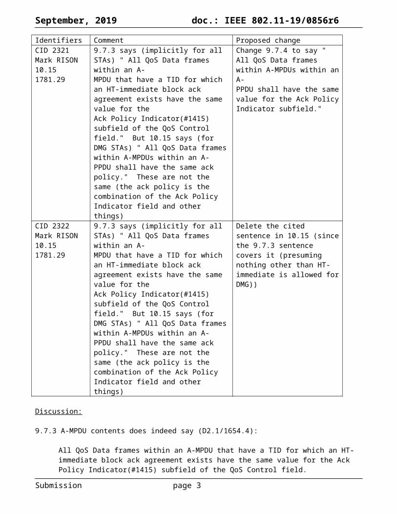


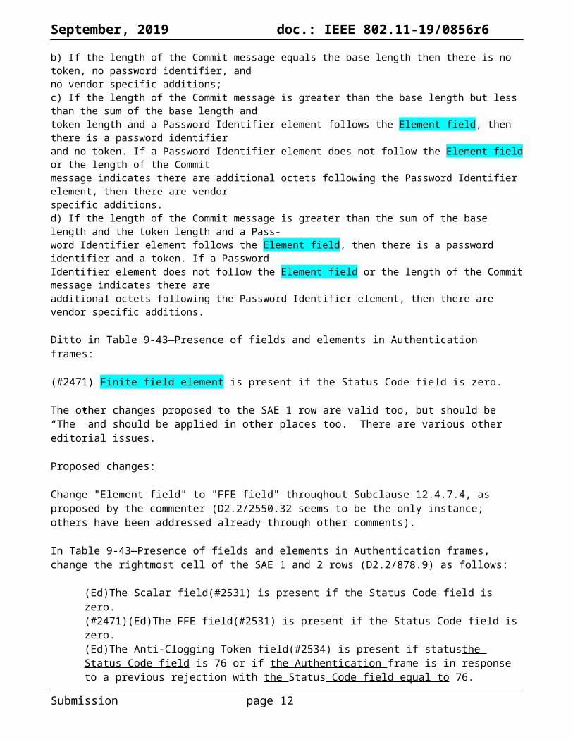


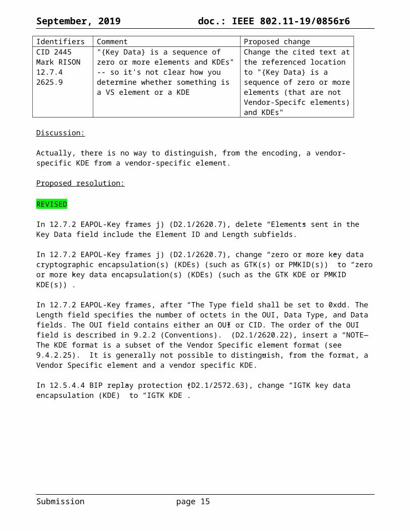
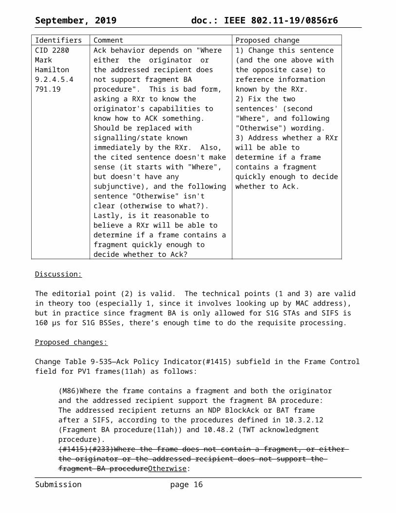


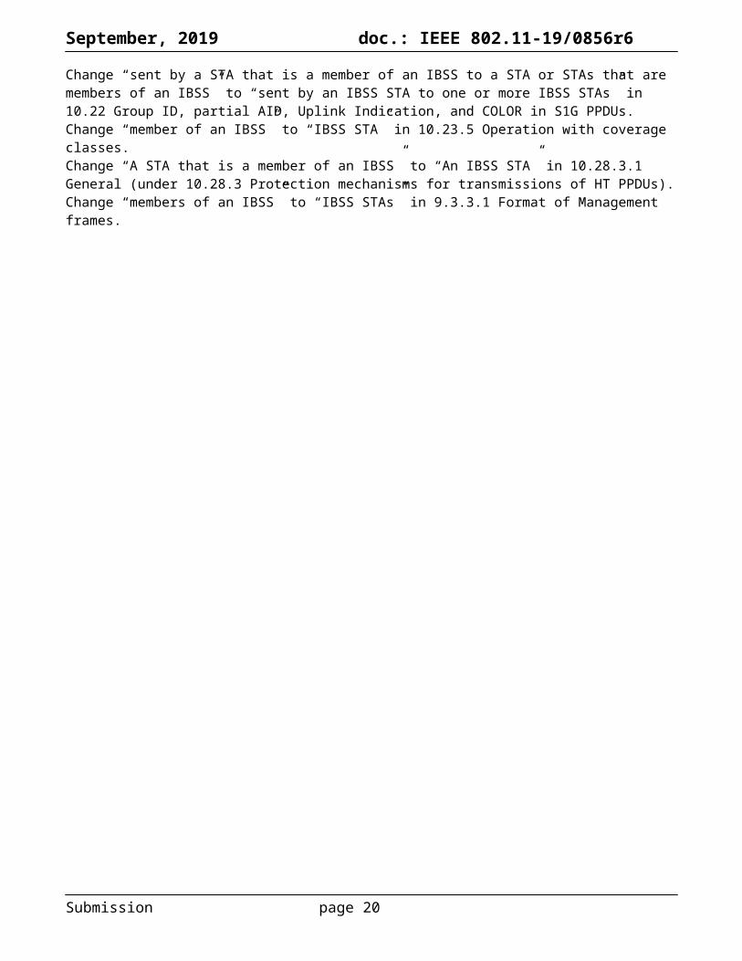


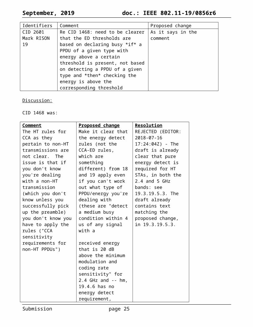

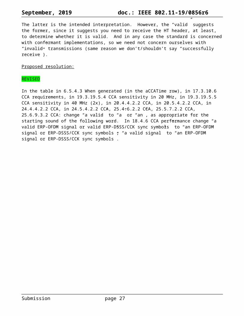
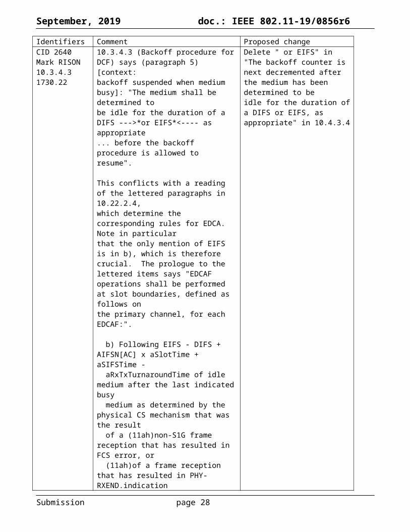


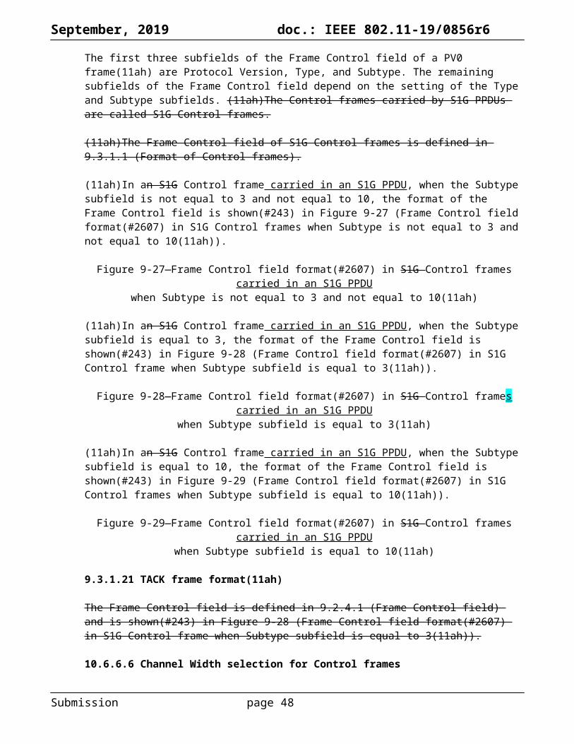


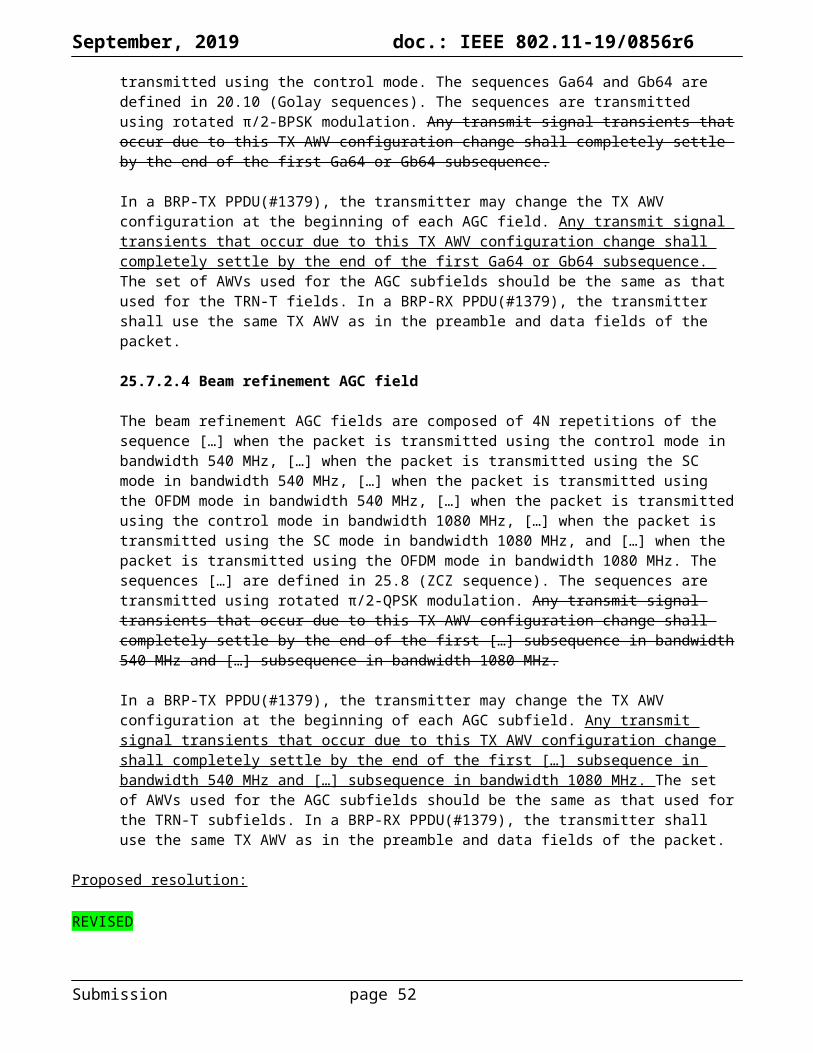


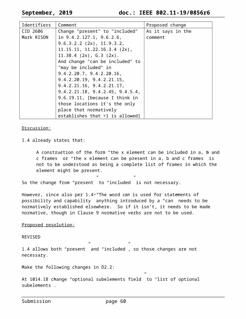


![SUPPLEMENTARY INFORMATIONraible/nclimate1816-s1.pdf · [5]) and thus not record the complete range of climate variability and datasets can also have gaps (Fig. S1g, [6], here filled](https://static.documents.pub/doc/80x56/5f64a358907a4f1df10c160d/supplementary-information-raiblenclimate1816-s1pdf-5-and-thus-not-record.jpg)


![doc.: IEEE 802.11-11/1137r13 · Web view[2012 July meeting minutes, 11-12/816r1] 3.2 S1G PLCP Sublayer R.3.2.A: 11ah defines single stream pilots in the LTF, SIG and Data fields of](https://static.documents.pub/doc/80x56/6048d43bc708fc108b73ab63/doc-ieee-80211-111137r13-web-view-2012-july-meeting-minutes-11-12816r1-32.jpg)


