22
Aesculap ® Aesculap Spine Instructions for use/Technical description A-Space SIBD and Arcadius XP L Instruments
| Date post: | 31-Jan-2016 |
| Category: |
Documents |
| Upload: | gusmargono |
| View: | 243 times |
| Download: | 0 times |

Aesculap®
Aesculap Spine
Instructions for use/Technical description
A-Space SIBD and ArcadiusXP L Instruments
1 2 3 4 5 6 7
8 9 10 11 12 13 14 15 16 17

18 19 20 21 22 23 24 25

2
Aesculap® A-Space SIBD and ArcadiusXP L Instruments
Aesculap®A-Space SIBD and ArcadiusXP L Instruments
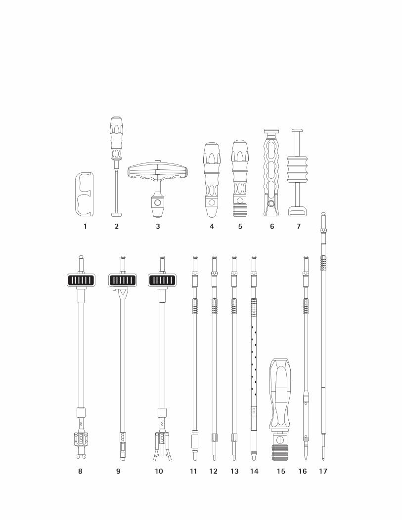
Legend 1 Packing Block (SJ604R)2 Tamp (SJ608R)3 T-Handle (SJ033R)4 Handle (FW440R)5 Ratchet Handle (SJ705R)6 Slap Hammer Handle (SJ708T)7 Slap Hammer Extension (SJ709R)8 Implant Introducer (SJ605R)*9 Trial Insertion Instrument (ME020R)10 Implant Inserter Manipulator (ME015R)11 U-Joint Screwdriver (ME014R)12 Straight Ball Hex Screwdriver (ME013R)13 Straight Hex Screwdriver (ME016R)14 Flexible Screw Driver (SJ706R)15 Torque Limiting Handle (ME012R)16 Flexible Bone Awl (SJ607R)17 Straight Bone Awl (ME017R)18 Straight Drill (SJ725R)19 Flexible Drill (SJ723R)20 Straight Drill Guide (SJ724R)21 Angled Drill Guide (SJ722R)22 Impactor (SJ606R)23 Implant Extraction Instrument (ME018R)24 Trial Implant (SJ664T – SJ798T: 36 sizes)25 Distractor 10 mm–20 mm (SJ020R, SJ022R,
SJ024R, SJ026R, SJ028R, SJ030R)* Instrument offered upon customer request only, notincluded in the instrument set.
Symbols on product and packages
Applicable to� A-Space SIBD and ArcadiusXP L� For item-specific instructions for use and informa-
tion on material compatibility, see also theAesculap Extranet at www.extranet.bbraun.com
Intended useThe A-Space SIBD and ArcadiusXP L Instruments areused for the implantation of A-Space SIBD andArcadiusXP L devices into the lumbar spine. Indicationsand contraindications are listed in the instructions foruse for the implants (TA013175 and TA015555).
Caution, general warning symbolCaution, see documentation sup-plied with the product

3
Safe handling and preparationCAUTION
Federal law restricts this device to sale by, or on
order of a physician!
� Always follow the instructions for use of the A-Space SIBD and ArcadiusXP L implants (TA013175and TA015555) and the respective surgical tech-niques.
� Ensure that the product and its accessories areoperated and used only by persons with the requi-site training, knowledge, or experience.
� Read, follow, and keep the instructions for use.� Use the product only in accordance with its
intended use, see Intended use.� Remove the transport packaging and clean the new
product, either manually or mechanically, prior toits initial sterilization.
� Store any new or unused products in a dry, clean,and safe place.
� Prior to each use, inspect the product for loose,bent, broken, cracked, worn, or fractured compo-nents.
� Do not use the product if it is damaged or defec-tive. Set aside the product if it is damaged.
� Replace any damaged components immediatelywith original spare parts.
Safe operation
Distraction
� Desired distraction of the vertebral bodies can beachieved by using the Distractors (SJ020R -SJ030R).
� Desired working height can be gradually achievedby coupling a Distractor to a T-Handle (SJ033R),inserting horizontally into the disc space androtating by 90°.
WARNING
Risk of injury and/or product
malfunction!
� Always carry out a func-
tion check prior to using
the product.
WARNING
Risk of damage to the spinal
cord, spinal nerve roots, adja-
cent intervertebral bodies or
soft tissue when inserting and
using the Distractor!
� Do not over insert the Dis-
tractor into the disc space.
� Do not over distract the
disc space.

4
Aesculap® A-Space SIBD and ArcadiusXP L Instruments
Selection of Implant Size Using Trial
Implants
� Attach selected Trial Implant to the Trial InsertionInstrument (ME020R) by inserting the Instrumentinto the anterior face of the Trial Implant. Turn thewheel clockwise to engage the Trial Implant ontothe Trial Insertion Instrument.
� To advance the Trial Implant into the disc space useeither a mallet or a Slap Hammer Extension(SJ709R) assembled onto a Slap Hammer Handle(SJ708T).
� Under lateral and anterior-posterior fluoroscopyconfirm the:– Implant depth, height, and lordosis– Endplate coverage (anterior-posterior / medial-
lateral)– Midline placement– Implant rotation
� Select the implant size that corresponds with thefinal Trial Implant size chosen.
Filling the Implant
� Fill the implant with bone or bone replacementmaterial by using the Packing Block (SJ604R) andTamp (SJ608R).
WARNING
Risk of over distracting, dam-
aging the endplates, or adja-
cent vertebral bodies in the
course of incorrectly applying
the Trial Insertion Instrument!
� During the Trial Implant
insertion, do not apply an
excessive bending/tilting/
levering force to the Trial
Insertion Instrument
(ME020R).
� Keep the instrument
directly in the plane of the
disc.
WARNING
If the Trial implant is inserted
too deep there is a risk of
damage to the spinal cord, spi-
nal nerve roots, posterior
structures!
� Always use the Trial Inser-
tion Instrument (ME020R)
with a depth stop.
� Do not apply excessive
hammering force.
WARNING
Risk of selecting incorrect
implant size!
� Fluoroscopy is mandatory
to confirm the final Trial
Implant size.
� Trial Implant must provide
good contact with the
inferior and superior end-
plates. Therefore the
proper footprint, height,
and lordotic angle should
be chosen for the disc
space.

5
Implant Placement and Positioning
� Securely attach the implant (corresponding to thefinal Trial Implant size) to the distal end of theinsertion instrument by turning the wheel clock-wise.
The laser markings (CRANIAL/CAUDAL) on the implantinsertion instrument indicate the correct orientationfor implant engagement.:� The Implant Inserter/Manipulator (ME015R) will
grip the implant utilizing the two lateral implantscrew holes.
� The Implant Introducer (SJ605R) will grip theimplant utilizing the two medial implant screwholes.
� Use appropriate care when inserting the implant.– Drive the Implant into the disc space using
either a mallet or the Slap Hammer Extension(SJ709R) assembled onto the Slap HammerHandle (SJ708T).
� Confirm an anatomically suitable position and ori-entation of the implant. It is recommended to con-firm implant position prior to removing the implantinserter.– Obtain an AP fluoroscopic image to confirm
midline placement of the device.– Obtain a lateral fluoroscopic image to confirm
that the anterior edge of the implant is seatedflush with the anterior border of the vertebralbody.
– Observe the X-Ray markers in both the AP andlateral views to ensure that the implant is notrotated within the disc space.
� Use Impactor (SJ606R) to adjust the position (in APdirection) of the implant as necessary.
Bone Screw Placement
� Use the bone awls (Straight Bone Awl (ME017R) orFlexible Bone Awl (SJ607R)) and the drills (StraightDrill (SJ725R) or Flexible Drill (SJ723R)) to preparea pilot hole for the bone screws at the intendedscrew placement site.
WARNING
Inaccurate marking of the
midline may result in incorrect
positioning of the implant!
� Always mark the midline
under X-ray visualization.
� Determine the center of
the vertebral disc using the
midline marker, under X-
Ray visualization.
WARNING
If the implant is inserted too
deep, the spinal canal and
other posterior elements may
be compressed!
� Always use the Implant
Inserter/Manipulator
(ME015R) with a depth
stop.
� Excessive hammering may
over-insert implant.
WARNING
Risk of damaging biological
structures (spinal cord, spinal
nerve roots, ligaments, vessels,
soft tissues, etc.) with the
drills and the bone awls, espe-
cially if the PEEK cage is
placed off midline!
� The instruments are sharp,
always use the bone awls/
drills under X-Ray control.

6
Aesculap® A-Space SIBD and ArcadiusXP L Instruments
� Always use the Drills and Straight Bone Awl withthe drill guides (Straight Drill Guide (SJ724R) orAngled Drill Guide (SJ722R)).
� Attach bone screw of appropriate length to theselected self-retaining screwdriver (Straight HexScrewdriver (ME016R), Straight Ball Hex Screw-driver (ME013R), Flexible Screw Driver (SJ706R),and U-Joint Screwdriver (ME014R)).
� Place a bone screw through selected screw hole onthe anterior face of the implant.
WARNING
Risk of damaging biological
structures (spinal nerve roots,
ligaments, vessels, soft tissues,
etc.) upon disengaging the
flexible instruments!
� The working end of the
Flexible Bone Awl
(SJ607R) may elastically
spring back to the original
shape upon disengagement
from the Implant and the
working end of the Flexible
Drill (SJ723R) may elasti-
cally spring back to the
original shape upon disen-
gagement from the Angled
Drill Guide (SJ722R).
� Follow Surgical technique,
or training by Aesculap.
WARNING
Risk of damaging biological
structures (spinal cord, spinal
nerve roots, ligaments, vessels,
soft tissues, etc.) due to
Straight Bone Awl tip or
Straight Drill tip breaking!
� Do not apply an excessive
bending/tilting/levering
force to the Straight Bone
Awl (ME017R) or Straight
Drill (SJ725R).
WARNING
Risk of damaging PEEK cage
with incorrectly applied
Straight Drill Guide (SJ724R)!
� Do not apply an excessive
bending/tilting/levering
force to the instrument.
WARNING
Engaging the screwdriver
incorrectly when turning the
bone screw into the PEEK cage
may result in damage to the
bone screws!
� Fully insert the tip of the
screwdriver into the bone
screw.
WARNING
Risk of damaging biological
structures (spinal cord, spinal
nerve roots, ligaments, vessels,
soft tissues, etc.) while
advancing incorrectly sized
bone screws, especially if the
PEEK cage is placed off mid-
line!
� Always advance the bone
screws, especially the
diverging lateral screws,
under X-Ray control.
� Follow Surgical technique,
or training by Aesculap.
WARNING
Applying too much torque may
result in damage to the bone
screws and the PEEK cages!
� Use of the Torque Limiting
Handle (ME012R) is rec-
ommended.

7
� Turn the screwdriver in a clockwise motion toadvance the bone screw into the vertebral body.
� Insert the bone screws until they reach the finalseated position, ensuring full engagement of thetwo locking mechanisms.
� Repeat the bone screw placement steps outlinedabove to insert the remaining bone screws throughthe implant.
Revision
� Locate implant, which is to be revised, and engageselected self-retaining screwdriver (Straight HexScrewdriver (ME016R), Straight Ball Hex Screw-driver (ME013R), Flexible Screw Driver (SJ706R), orU-Joint Screwdriver (ME014R)) in the bone screwhead.
� Retract the bone screw from the vertebral body byturning the screw in a counterclockwise motion.
� Repeat the bone screw removal process with theremaining bone screws in the PEEK cage.
� Engage Implant Extraction Instrument (ME018R)or the Implant Inserter/Manipulator (ME015R) tothe implant and remove it from the disc space.
NoteIf a fully seated bone screw is removed from theimplant, a small piece of PEEK debris from the lockingrim in the locking mechanism may be present.
WARNING
Risk of damage to the PEEK
cage, or the bone screw head
in the course of incorrectly
driving the bone screw!
� Do not apply an excessive
bending/tilting/levering
force to the Straight Hex
Screwdriver (ME016R) or
Straight Ball Hex Screw-
driver (ME013R) engaged
in the bone screw.
� Keep the screwdrivers
directly aligned with the
axis of the bone screws.
WARNING
The screws could back out or
loosen if they are not fully
inserted into the cage!
� Insert the bone screw until
it is fully engaged.
� Follow Surgical technique,
or training by Aesculap.
WARNING
Risk of insufficient stability or
implant failure if fewer than
four screws are used!
� Apply all four screws or use
an additional supplemental
spinal fixation system such
as the Aesculap S4 Spinal
System.
WARNING
Risk of injury to the patient!
� Remove implant in the
direction it was inserted.
� Excessive force during
extraction may cause
implant to dislodge sud-
denly and impact the sur-
rounding tissues.

8
Aesculap® A-Space SIBD and ArcadiusXP L Instruments
General
� Caution should be taken while operating theinstruments with quick connect modular handles:T-Handle (SJ033R), Handle (FW440R), RatchetHandle (SJ705R), Slap Hammer Handle (SJ708T)and Torque Limiting Handle (ME012R).
� Caution should be taken for assembling the follow-ing modular instruments: Implant Inserter/Manip-ulator (ME015R), Implant Introducer (SJ605R),Flexible Drill (SJ723R), Straight Hex Screwdriver(ME016R) and Straight Ball Hex Screwdriver(ME013R).
Disassembling
Straight Ball Hex Screwdriver (ME013R)
and Straight Hex Screwdriver (ME016R)
� Unthread the nut 30 from the distal end of theshaft.
� Remove the screwdriver bit 31 from the shaft.� Remove the soft tissue protection sleeve 32 from
the shaft, see Fig. 1.
Fig. 1 Disassembling ME013R and ME016R
WARNING
Activating the "PRESS" button
on the handle while actively
using the instruments can
result in the instrument shaft
detaching from the handle!
� Do not cover the "PRESS"
button with hand when
utilizing fully assembled
instruments.
WARNING
Risk of not being able to
securely engage implant or
damaging the instrument with
incorrectly assembled Implant
Inserter/Manipulator
(ME015R) or Introducer
(SJ605R)!
� Ensure that the instru-
ments are correctly assem-
bled prior to the surgery.
WARNING
Danger from improperly
assembled Flexible Drill
(SJ723R): the flexible drill bit
may disengage from the
instrument shaft!
� Prior to the surgery, ensure
that the drill bit is secured
to the instrument shaft by
firmly tightening the nut
until it is fully threaded.
WARNING
Danger from improperly
assembled Straight Hex
Screwdriver (ME016R) or
Straight Ball Hex Screwdriver
(ME013R): the screwdriver bit
may disengage from the
instrument shaft!
� Prior to surgery, ensure
that the screwdriver bit is
secured to the instrument
shaft, by firmly tightening
the nut until it is fully
threaded.
3130
32

9
U-joint screwdriver (ME014R) and
Implant Extraction Instrument (ME018R)
� Remove the spring 33 covering the u-joint fromthe distal end of the shaft, see Fig. 2 and see Fig. 3.
Fig. 2 Disassembling ME014R
Fig. 3 Disassembling ME018R
Flexible Drill (SJ723R)
� Unthread the nut 34 from the distal end of theshaft.
� Remove the drill bit 35 from the shaft end, see Fig.4.
Fig. 4 Disassembling SJ723R
Implant Inserter Manipulator (ME015R)
and Implant Introducer (SJ605R)
� While holding the proximal end (mechanism withthumb wheel) upright, unthread the nut 36 coun-terclockwise towards the proximal end.
� With the nut disengaged from its threading, turnthe thumb wheel 37 clockwise ("LOCK" - direction)until the sub-assembly 38 disengages from theouter sheath 39.
� Pull out the sub-assembly 38 from the outersheath 39.
� Remove the depth stopper 40 by pushing it distallyparallel along the shaft until it disengages from its
33
33
3435

10
Aesculap® A-Space SIBD and ArcadiusXP L Instruments
rail, see Fig. 5 and see Fig. 6.
Fig. 5 Disassembling ME015R
Fig. 6 Disassembling SJ605R
Trial Insertion Instrument (ME020R)
� Press the locking mechanism button 41 near thethumb wheel and pull out the outer sheath 42.
� Remove the inner shaft 43 from the thumb wheel.� Remove the depth stopper 44 by pushing it distally
parallel along the shaft until it disengages from itsrail.
Fig. 7 Disassembling ME020R
36
38
3840
39
37
36
38
3840
39
37
43
42
41
44

11
Assembling
Straight Ball Hex Screwdriver (ME013R)
and Straight Hex Screwdriver (ME016R)
� Place the soft tissue protection sleeve 32 over theinner shaft.
� Insert the screwdriver bit 31 into the internalhexagon of the distal end of the shaft.
� Firmly thread the nut 30 proximally over thescrewdriver bit until it is fully threaded, see Fig. 8.
Fig. 8 Assembling ME013R and ME016R
U-joint screwdriver (ME014R) and
Implant Extraction Instrument (ME018R)
� Slide the spring 33 over the distal end until it iscompletely covering the u-joint, see Fig. 9 and seeFig. 10. The ends of the spring should sit within theflange on the shaft and the flange on the distalhead, see Fig. 11.
Fig. 9 Assembling ME014R
Fig. 10 Assembling ME018R
Fig. 11 Correct spring position
WARNING
Danger from improperly
assembled Straight Hex
Screwdriver (ME016R) or
Straight Ball Hex Screwdriver
(ME013R): the screwdriver bit
may disengage from the
instrument shaft during ship-
ment or operation!
� Ensure the screwdriver
bit 31 is secured to the
shaft, by firmly tightening
the nut 32 until it is fully
threaded
32
31
30
33
33

12
Aesculap® A-Space SIBD and ArcadiusXP L Instruments
Flexible Drill (SJ723R)
� Insert the drill bit 35 into the internal hexagon ofthe distal end of the shaft.
� Firmly thread the nut 34 over the drill bit towardsthe proximal end until it is fully threaded, see Fig.12.
Fig. 12 Assembling SJ723R
Implant Inserter Manipulator (ME015R)
and Implant Introducer (SJ605R)
� Place the depth stopper 40 on its rail and press itproximally along the shaft until it is fully engaged.
� Insert the sub-assembly 38 all the way into theouter sheath 39.
� Start turning the thumb wheel 37 counterclock-wise ("RELEASE"-direction) while pressing the sub-assembly towards the thumb wheel.The threads between the end of the sub-assemblyshaft and the inner thread in the thumb wheel willstart to engage.
� Continue turning the thumb wheel until the pro-trusions of the sub-assembly are flush with theslots in the outer sheath.
� Visually verify that both components (38 and 39)are fully engaged, see Fig. 15.
WARNING
Danger from improperly
assembled Flexible Drill
(SJ723R): the flexible drill bit
may disengage from the
instrument shaft during ship-
ment or operation!
� Ensure that the drill bit 35
is secured to instrument
shaft, by firmly tightening
the nut 34 until it is fully
threaded.
3435
WARNING
Risk of not being able to
securely engage the implant or
damaging the instrument with
incorrectly assembled Implant
Inserter/Manipulator
(ME015R) or Introducer
(SJ605R)!
� Ensure that there is no gap
between components 38
and 39.
� Firmly tighten the nut 36
until it is fully threaded.

13
� Firmly thread the nut 36 towards the distal enduntil it is fully threaded, see Fig. 13 and see Fig. 14.
Fig. 13 Assembling ME015R
Fig. 14 Assembling SJ605R
Fig. 15 Correct engagement of sub-assembly andouter sheath
Trial Insertion Instrument (ME020R)
� Place the depth stop 44 on its rail and press itproximally along the shaft until it is fully engaged.
� Insert the hexagonal end of the inner shaft 43 intothe inner hexagon of the thumb wheel 45.
� Place the outer sheath 42 over the inner shaft 43.� Press the locking mechanism button 41 and fully
insert the outer sheath into the locking mechanism(until it reaches the hard stop).
� Release the button 41, see Fig. 16.
Fig. 16 Assembling ME020R
40
38
38
39
37
36
36
4038
38
39
37
t = 0
39383938
t > 0
43
42
45
4441

14
Aesculap® A-Space SIBD and ArcadiusXP L Instruments
Validated reprocessing procedure
Disassembling the product before carry-
ing out the reprocessing procedure
� Disassemble the product immediately after use, seeDisassembling.
Preparation before cleaning
� Dismantle the product prior to cleaning, see Disas-sembling.
Cleaning/disinfection
Product-specific safety notes on the repro-
cessing procedure
� Use suitable cleaning/disinfecting agents if theproduct is put away in a wet condition. To preventfoam formation and reduced effectiveness of theprocess chemicals: Prior to mechanical cleaningand disinfection, rinse the product thoroughly withrunning water.
� Carry out ultrasound cleaning:– as an effective mechanical supplement to man-
ual cleaning/disinfecting.– as a pre-cleaning procedure for products with
encrusted residues, in preparation for mechan-ical cleaning/disinfecting.
– as an integrated mechanical support measurefor mechanical cleaning/disinfecting.
– for additional cleaning of products with resi-dues left after mechanical cleaning/disinfect-ing.
DANGER
Risk to patients!
� The Ratchet Handle
(SJ705R), Slap Hammer
Handle (SJ708T), Slap
Hammer Extension
(SJ709R), Torque Limiting
Handle (ME012R), Implant
Inserter Manipulator
(ME015R), Implant Intro-
ducer (SJ605R), Straight
Drill Guide (SJ724R), and
Trial Insertion Instrument
(ME020R) must only be
cleaned mechanically.
CAUTION
Damage to the product due to
inappropriate cleaning/disin-
fecting agents and/or exces-
sive temperatures!
� Use cleaning and disinfect-
ing agents according to the
manufacturer’s instruc-
tions which are approved
for high-grade steel.
� Observe specifications
regarding concentration,
temperature and exposure
time.

15
Validated cleaning and disinfection procedure
NoteReprocessing may only take place in accordance with the following listed procedures in version V6. These are doc-umented in the Validated Reprocessing Procedures brochure (AVA-V6). You can also find this brochure in theAesculap extranet at www.extranet.bbraun.com
Validated procedure Specific requirements Reference
Manual cleaning with immersion disinfection� ME013R
� ME014R
� ME016R
� ME018R
� SJ604R
� SJ606R
� SJ607R
� SJ608R
� SJ722R
� SJ723R
� SJ725R
� SJ020R – SJ030R (6 sizes)
� SJ664T – SJ798T (36 sizes)
� Cleaning brush: e.g. TA011944, TE654202, GK469200
� Disposable syringe 20 ml
� When cleaning products with movable hinges, ensure that these are in an open position and, if applicable, move the joint while cleaning.
� Drying phase: Use a lint-free cloth or medical compressed air
Chapter Manual cleaning/disinfection and sub-chapter:� Chapter Manual cleaning with
immersion disinfection
Manual cleaning with ultrasound and immer-sion disinfection� SJ706R
� Cleaning brush: e.g. TA011944, TE654202, GK469200
� Disposable syringe 20 ml
� When cleaning products with movable hinges, ensure that these are in an open position and, if applicable, move the joint while cleaning.
� Drying phase: Use a lint-free cloth or medical compressed air
Chapter Manual cleaning/disinfection and sub-chapter:� Chapter Manual cleaning with
ultrasound and immersion disinfection

16
Aesculap® A-Space SIBD and ArcadiusXP L Instruments
Mechanical alkaline cleaning and thermal disinfection� FW440R
� SJ033R
� SJ604R
� SJ606R
� SJ608R
� SJ725R
� SJ020R – SJ030R (6 sizes)
� Place the product in a tray that is suitable for cleaning (avoiding rinsing blind spots).
� Place products in the tray with their hinges open.
Chapter Mechanical cleaning/disinfecting and sub-chapter:� Chapter Mechanical alkaline cleaning
and thermal disinfecting
Manual pre-cleaning with brush and subse-quent mechanical alka-line cleaning and ther-mal disinfection� ME012R
� ME013R
� ME014R
� ME016R
� ME018R
� SJ607R
� SJ705R
� SJ708T
� SJ722R
� SJ723R
� SJ664T – SJ798T (36 sizes)
� Cleaning brush: e.g. TA011944, TE654202, GK469200
� Disposable syringe 20 ml
� Place the product in a tray that is suitable for cleaning (avoiding rinsing blind spots).
� Place products in the tray with their hinges open.
Chapter Mechanical cleaning/disinfection with manual pre-cleaning and sub-chap-ter:� Chapter Manual pre-cleaning with a
brush
� Chapter Mechanical alkaline cleaning and thermal disinfecting
Validated procedure Specific requirements Reference

17
Inspection, maintenance and checks
� Allow the product to cool down to room tempera-ture.
� After each complete cleaning, disinfecting and dry-ing cycle, check that the product is dry, clean,operational, and free of damage (e.g. broken insu-lation or corroded, loose, bent, broken, cracked,worn, or fractured components).
� Dry the product if it is wet or damp.� Repeat cleaning and disinfection of products that
still show impurities or contamination.� Check that the product functions correctly.� Immediately put aside damaged or inoperative
products and send them to Aesculap Technical Ser-vice, see Technical Service.
� Assemble dismountable products, see Assembling.� Check for compatibility with associated products.
Packaging
� Appropriately protect products with fine workingtips for the following instruments: SJ607R,ME017R, SJ723R, SJ725R, SJ706R, ME013R,ME014R and ME016R.
� Place the product in its holder or on a suitable tray.Ensure that all cutting edges are protected.
� Pack trays appropriately for the intended steriliza-tion process (e.g. in Aesculap sterile containers).
� Ensure that the packaging provides sufficient pro-tection against recontamination of the productduring storage.
Manual pre-cleaning with ultrasound and brush, and subsequent mechanical alkaline cleaning and thermal disinfection� ME015R
� SJ605R
� ME020R
� SJ706R
� SJ709R
� SJ724R
� Cleaning brush: e.g. TA011944, TE654202, GK469200
� Disposable syringe 20 ml
� Place the product in a tray that is suitable for cleaning (avoiding rinsing blind spots).
� Place products in the tray with their hinges open.
Chapter Mechanical cleaning/disinfection with manual pre-cleaning and sub-chap-ter:� Chapter Manual pre-cleaning with
ultrasound and brush
� Chapter Mechanical alkaline cleaning and thermal disinfecting
Validated procedure Specific requirements Reference
CAUTION
Damage (metal seizure/fric-
tion corrosion) to the product
caused by insufficient lubrica-
tion!
� Prior to function checks,
lubricate moving parts (e.g.
joints, pusher components
and threaded rods) at the
marked lubrication points,
using maintenance oil suit-
able for the respective
sterilization process (e.g.
for steam sterilization:
Aesculap STERILIT® I oil
spray JG600 or STERILIT® I
drip lubricator JG598).

18
Aesculap® A-Space SIBD and ArcadiusXP L Instruments
Steam sterilization
NoteThe product can be sterilized either in disassembled orin assembled condition.
� Check to ensure that the sterilizing agent will comeinto contact with all external and internal surfaces(e.g. by opening any valves and faucets).
� Validated sterilization process– Steam sterilization through fractionated vac-
uum process– Steam sterilizer according to DIN EN 285 and
validated according to DIN EN ISO 17665– Sterilization using fractionated vacuum pro-
cess at 134 °C/holding time 5 min� When sterilizing several products at the same time
in a steam sterilizer, ensure that the maximum loadcapacity of the steam sterilizer specified by themanufacturer is not exceeded.
Sterilization for the US market
� Aesculap advises against sterilizing the device byflash sterilization or chemical sterilization.
� Sterilization may be accomplished by a standardprevacuum cycle in a steam autoclave.
To achieve a sterility assurance level of 10-6, Aesculaprecommends the following parameters:
*Aesculap has validated the above sterilization cycleand has the data on file. The validation was accom-plished in an Aesculap sterile container cleared by FDA
for the sterilization and storage of these products.Other sterilization cycles may also be suitable, how-ever individuals or hospitals not using the recom-mended method are advised to validate any alternativemethod using appropriate laboratory techniques. Usean FDA cleared accessory to maintain sterility afterprocessing, such as a wrap, pouch, etc.WARNING for the US market
If this device is/was used in a patient with, or sus-
pected of having Creutzfeldt-Jakob Disease (CJD),
the device cannot be reused and must be destroyed
due to the inability to reprocess or sterilize to elim-
inate the risk of crosscontamination.
Storage
� Store sterile products in germ-proof packaging,protected from dust, in a dry, dark, temperature-controlled area.
Aesculap Orga Tray/Sterile container (perforated
bottom)
Minimum cycle parameters*
Steriliza-
tion method
Temp. Time Minimum
drying
time
Prevacuum 270 °F/275 °F
4 min 30 min

19
Technical Service
� For service and repairs, please contact yournational B. Braun/Aesculap agency.
Modifications carried out on medical technical equip-ment may result in loss of guarantee/warranty rightsand forfeiture of applicable licenses.
Service addresses
Aesculap Technischer ServiceAm Aesculap-Platz 78532 Tuttlingen / GermanyPhone: +49 (7461) 95-1602Fax: +49 (7461) 16-5621E-Mail: [email protected] in the US: Aesculap Implant Systems LLC Attn. Aesculap Technical Services 615 Lambert Pointe Drive Hazelwood MO, 63042 Aesculap Repair Hotline Phone: +1 (800) 214-3392 Fax: +1 (314) 895-4420Other service addresses can be obtained from theaddress indicated above.
Disposal� Adhere to national regulations when disposing of
or recycling the product, its components and itspackaging!
Distributor in the US/Contact in Canada for product information and complaintsAesculap Implant Systems LLC 3773 Corporate Parkway Center Valley, PA, 18034,USA
WARNING
Risk of injury and/or malfunc-
tion!
� Do not modify the product.

- DIR 93/42/EEC Technical alterations reserved
Aesculap AG | Am Aesculap-Platz | 78532 Tuttlingen | GermanyPhone +49 (0) 7461 95-0 | Fax +49 (0) 7461 95-26 00 | www.aesculap.com
Aesculap – a B. Braun company TA-Nr. 015556 08/12 V6


