Page 1
8/18/2019 Docslide.us tggg Balancing of Rotors Ppt
http://slidepdf.com/reader/full/docslideus-tggg-balancing-of-rotors-ppt 1/60
DYNAMIC BALANCING OF ROTORS
ByDr. Rajiv Tiwari
Department of Mechanical Engineering
Indian Institute of Technology Guwahati !"#$%
&nder 'I(TE )ponsored *I+ )hort Term (ourse on
Theory & Practice of Rotor Dynamics
,"-"% Dec /##!0
IIT Guwahati
Dr. R. Tiwari ([email protected] ) 1
Page 2
8/18/2019 Docslide.us tggg Balancing of Rotors Ppt
http://slidepdf.com/reader/full/docslideus-tggg-balancing-of-rotors-ppt 2/60
Intro!ction
The unbalance in rotors will not only cause rotor vibrations, but also
transmit rotating forces to bearings and to the foundation structure.
The force thus transmitted may cause damage to machine parts and its
foundation. f the transmitted force is large enough, it might affect even the
neighboring machines and structures.
Thus, it is necessary to remove the unbalance of a rotor, to as large an
e!tend as possible, for its smooth running. The residual unbalance
estimation in rotor"bearing system is an age"old problem.
#rom the state of the art of the unbalance estimation, the unbalance can be
obtained with fairly good accuracy $1"%&.
'ow the trend in the unbalance estimation is to reduce the number of test
runs reuired, especially for the application of large turbo generators where
the downtime is very e!pDer.nRs.iTviewa$r i (,r *tiw&.ar
[email protected] )
+
Page 3
8/18/2019 Docslide.us tggg Balancing of Rotors Ppt
http://slidepdf.com/reader/full/docslideus-tggg-balancing-of-rotors-ppt 3/60
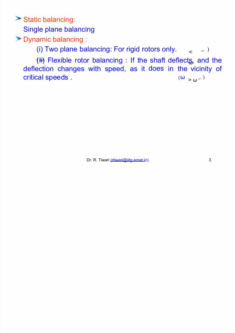
tatic balancing-
ingle plane balancing
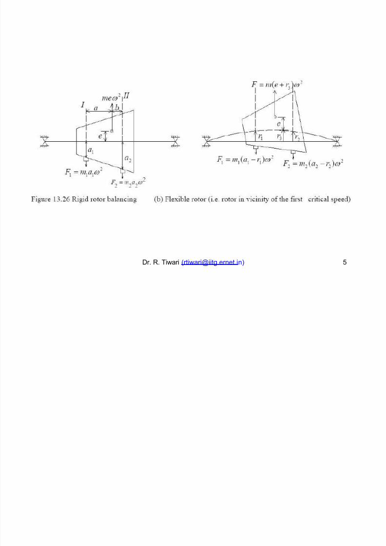
Dynamic balancing -(i) Two plane balancing- #or rigid rotors only.
( ω
<
ω
)cr
(ii) #le!ible rotor balancing - f the shaftdoes
deflects, and the
deflection changes with speed, as it in the(ω
vicinity of
critical speeds .ω>
)cr
Dr. R. Tiwari ([email protected] )
Page 4
8/18/2019 Docslide.us tggg Balancing of Rotors Ppt
http://slidepdf.com/reader/full/docslideus-tggg-balancing-of-rotors-ppt 4/60
Dr. R. Tiwari ([email protected] ) /
Page 5
8/18/2019 Docslide.us tggg Balancing of Rotors Ppt
http://slidepdf.com/reader/full/docslideus-tggg-balancing-of-rotors-ppt 5/60
Dr. R. Tiwari ([email protected] ) %
Page 6
8/18/2019 Docslide.us tggg Balancing of Rotors Ppt
http://slidepdf.com/reader/full/docslideus-tggg-balancing-of-rotors-ppt 6/60
Dr. R. Tiwari ([email protected] )
Page 7
8/18/2019 Docslide.us tggg Balancing of Rotors Ppt
http://slidepdf.com/reader/full/docslideus-tggg-balancing-of-rotors-ppt 7/60
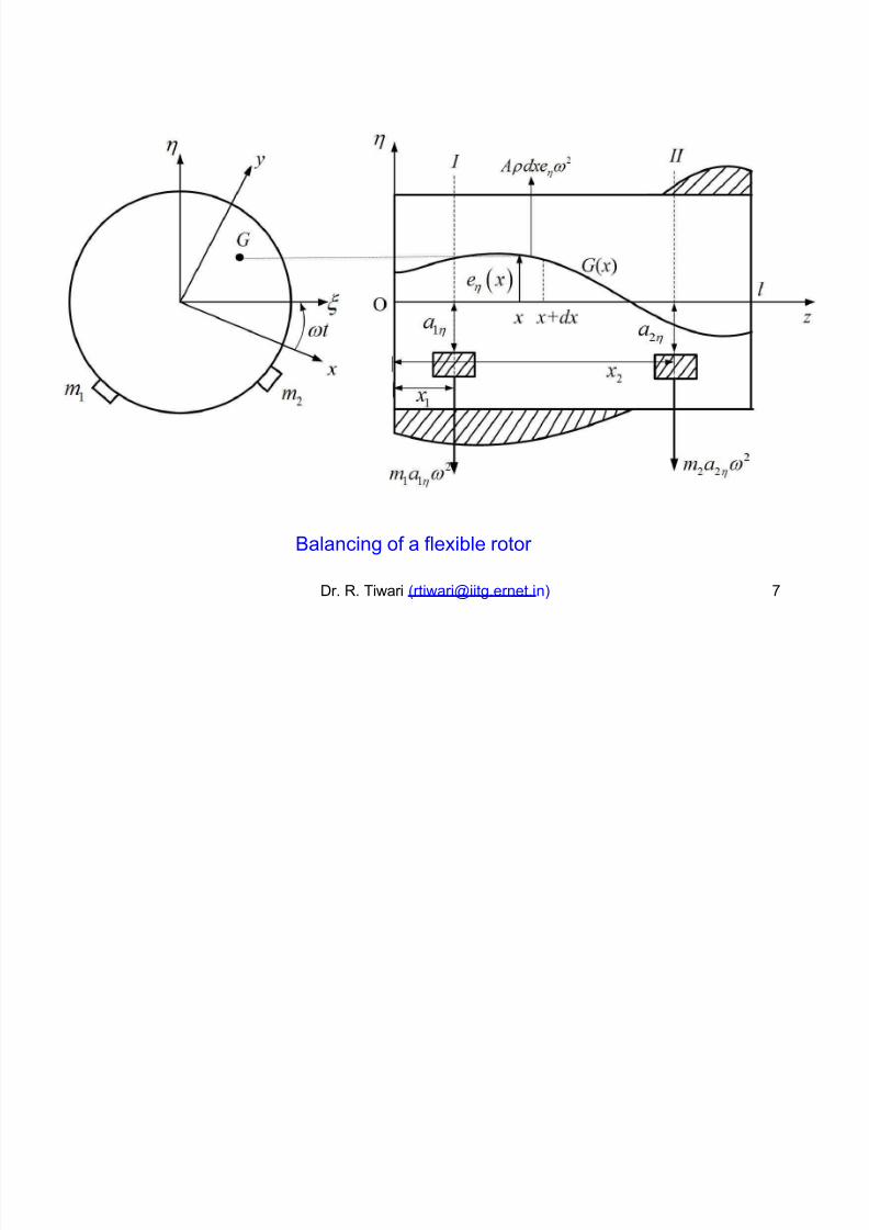
0alancing of a fle!ible rotor
Dr. R. Tiwari ([email protected] ) *
Page 8
8/18/2019 Docslide.us tggg Balancing of Rotors Ppt
http://slidepdf.com/reader/full/docslideus-tggg-balancing-of-rotors-ppt 8/60
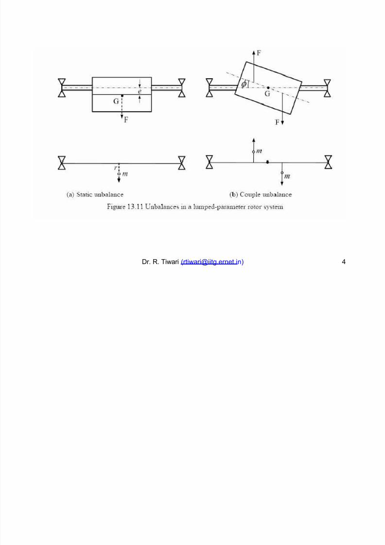
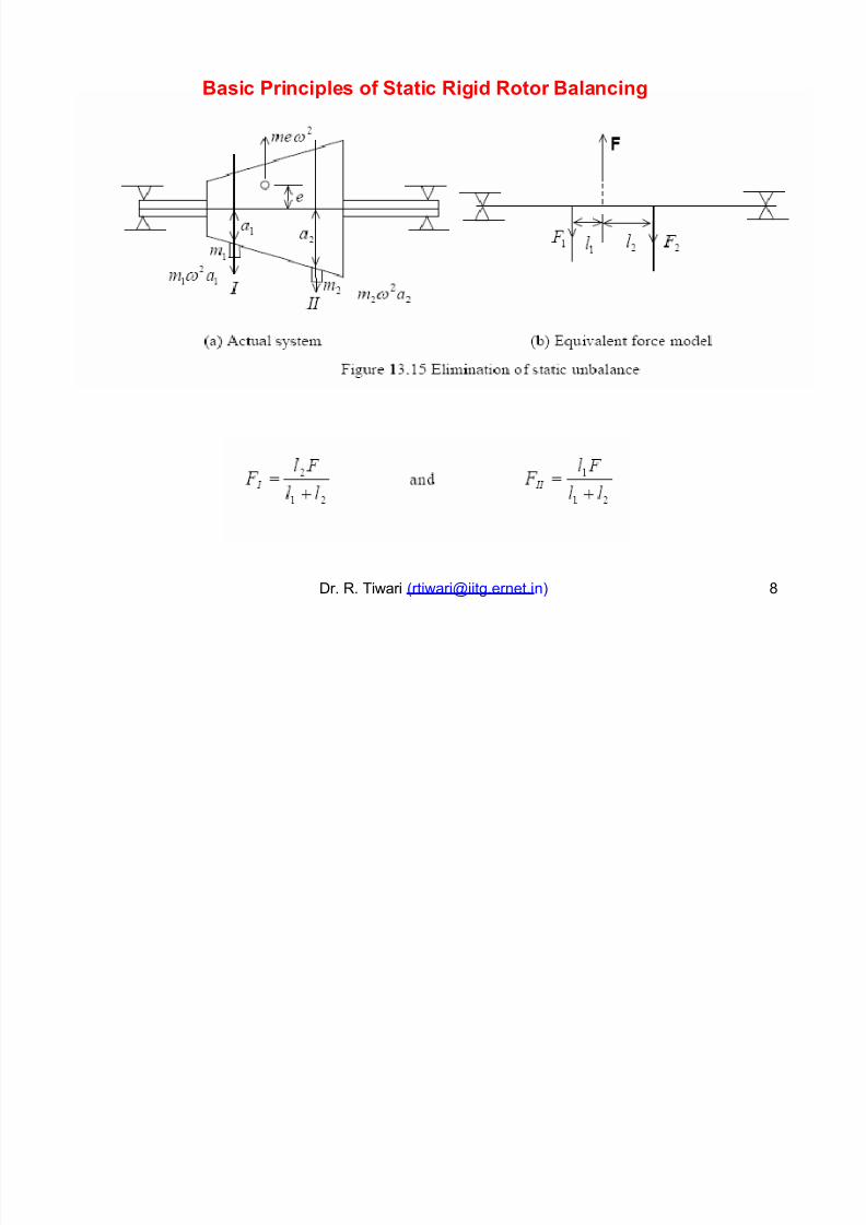
Basic Princi"#es of Static Ri$i Rotor Ba#ancin$
Dr. R. Tiwari ([email protected] )
Page 9
8/18/2019 Docslide.us tggg Balancing of Rotors Ppt
http://slidepdf.com/reader/full/docslideus-tggg-balancing-of-rotors-ppt 9/60
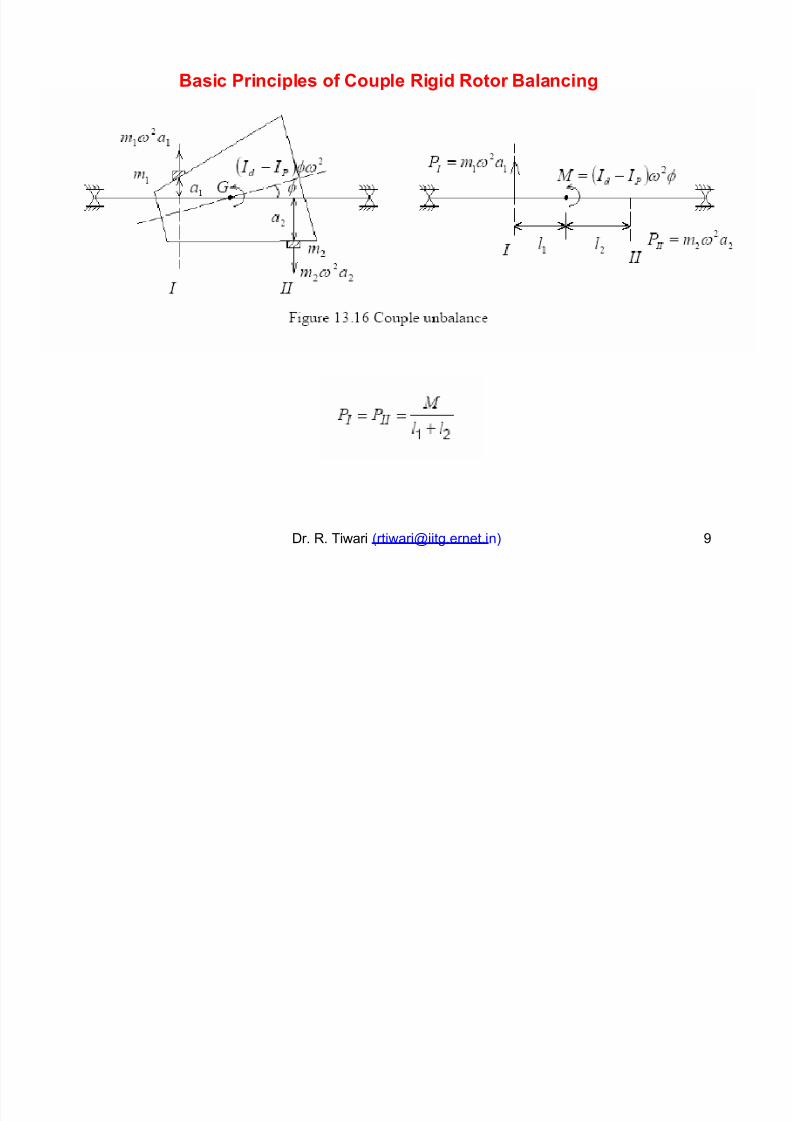
Basic Princi"#es of Co!"#e Ri$i Rotor Ba#ancin$
Dr. R. Tiwari ([email protected] ) 2
Page 10
8/18/2019 Docslide.us tggg Balancing of Rotors Ppt
http://slidepdf.com/reader/full/docslideus-tggg-balancing-of-rotors-ppt 10/60
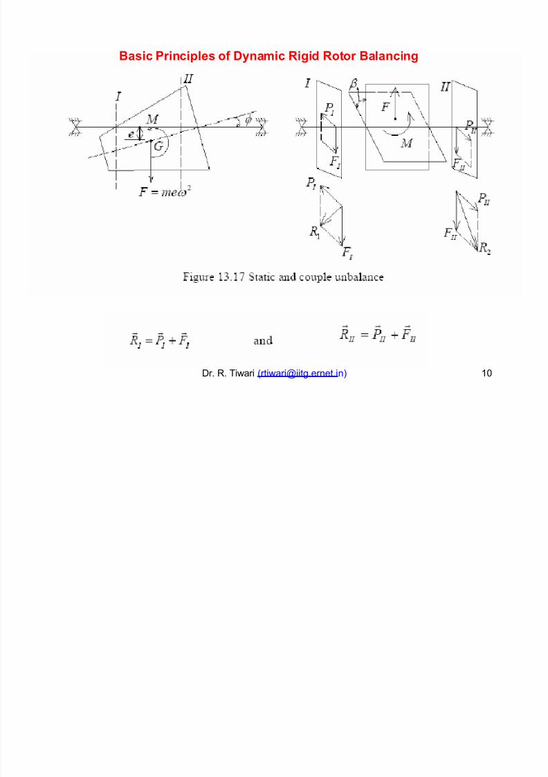
Basic Princi"#es of Dynamic Ri$i Rotor Ba#ancin$
Dr. R. Tiwari ([email protected] ) 13
Page 11
8/18/2019 Docslide.us tggg Balancing of Rotors Ppt
http://slidepdf.com/reader/full/docslideus-tggg-balancing-of-rotors-ppt 11/60
4
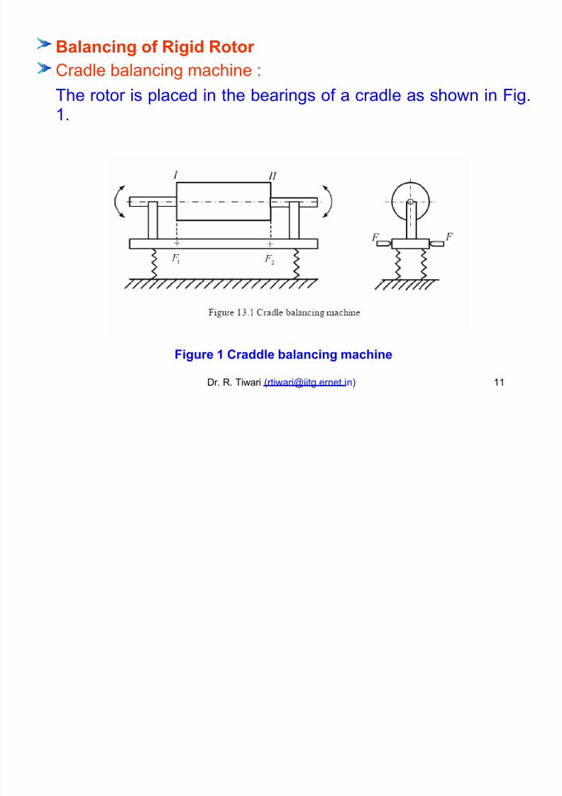
Ba#ancin$ of Ri$i Rotor
5radle balancing machine -
The1.
rotor is placed in the bearings of a cradle as shown in #ig.
Fi$!re % Cra#e a#ancin$ machine
Dr. R. Tiwari ([email protected] ) 11
Page 12
8/18/2019 Docslide.us tggg Balancing of Rotors Ppt
http://slidepdf.com/reader/full/docslideus-tggg-balancing-of-rotors-ppt 12/60
The cradle is placed on two springs and can be fulcrum about #1 or #+ to
form a simple vibrating system.
Two fulcrum can be located at two chosen balance planes (i.e. and ),
where the correction mass to be added.
The rotor can be driven by a motor through a belt pulley arrangement.
f the spring system is such that the natural freuency of the system is in the
range of motor speed, the
mass in either plane can be
phase angle or the location of the unbalance
determined as follows.
#ulcrum the cradle in plane, by fi!ing #1 and releasing #+. Run the rotor to
resonance, observing the ma!imum amplitude to the right of fulcrum #+.
This vibration is due to all the unbalance in plane ,
plane has no moment about #1.Dr. R. Tiwari ([email protected] )
since the unbalance in
1+
Page 13
8/18/2019 Docslide.us tggg Balancing of Rotors Ppt
http://slidepdf.com/reader/full/docslideus-tggg-balancing-of-rotors-ppt 13/60
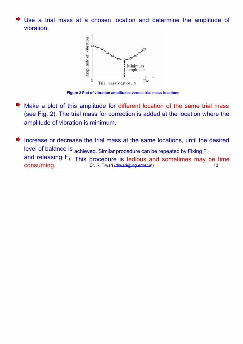
6se a trial
vibration.
mass at a chosen location and determine the amplitude of
Fi$!re ' P#ot of (iration am"#it!es (ers!s tria# mass #ocations
7a8e a plot
(see #ig. +).
of this amplitude for different location of the same trial mass
The trial mass for correction is added at the location where the
amplitude of vibration is minimum.
ncrease or decrease the trial mass at the same locations, until the desired
level of balance is
and releasing #1.
consuming.
achieved. imilar procedure can be repeated by #i!ing #+
This procedure is tedious and sometimes may be timeDr. R. Tiwari ([email protected] ) 1
Page 14
8/18/2019 Docslide.us tggg Balancing of Rotors Ppt
http://slidepdf.com/reader/full/docslideus-tggg-balancing-of-rotors-ppt 14/60
9 procedure to determine the correction mass and location can be laid
down as follows, based on four observations
(i) without any addition to the rotor
of amplitude -
(ii) with a trial mass at 8 : ;3
(iii) with a trial mass at 1;3
and
mass at 8
location.
: <2;3, where
8
(iv) with same trial
conveniently chosen
is measured from a
This procedure has to be repeated
and then for #+ ).
for two cases (e.g. when fulcruming at #1
(1) =et ;9 is the amplitude measured with trial run
(+) ;0 is the amplitude measured in trial run by addition of a trial mass W t
at ;3(arbitrary chosen location on rotor).Dr. R. Tiwari ([email protected] ) 1/
Page 15
8/18/2019 Docslide.us tggg Balancing of Rotors Ppt
http://slidepdf.com/reader/full/docslideus-tggg-balancing-of-rotors-ppt 15/60
>ence the vector 90 will represent the effect of trial mass W t .
(9t this stage we do not 8now the location of vector ;9 on therotor).
() ;5 is the vibration measured in the trial run with the trial mass at
1;3.
o we will have 90 : 95 with 1;3 phase difference between them.
(>ence 95 vector is also the effect of trial mass W t so the magnitudes 90 :
95 and phase will be 1;3).
>owever we 8now only ;9, ;0 ? ;5 from test run (1), (+) ? ()
respectively ? conditions 90 : 95 with 1;3phase.
#rom these information we have to construct or locate
a plane.
points ;, 9, 0 ? 5 on
Dr. R. Tiwari ([email protected] ) 1%
Page 16
8/18/2019 Docslide.us tggg Balancing of Rotors Ppt
http://slidepdf.com/reader/full/docslideus-tggg-balancing-of-rotors-ppt 16/60
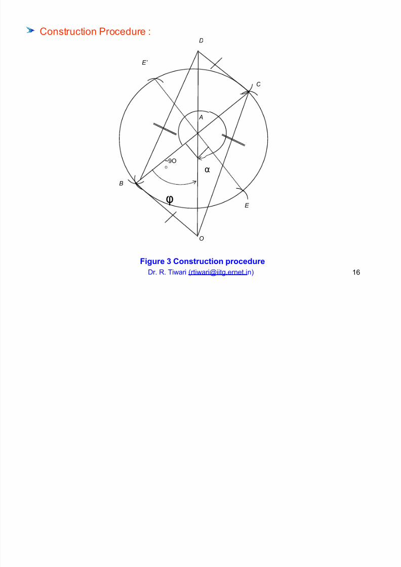
5onstruction rocedure -D
E’
C
A
A2;; α
B
φE
O
Fi$!re ) Constr!ction "roce!re
Dr. R. Tiwari ([email protected] ) 1
Page 17
8/18/2019 Docslide.us tggg Balancing of Rotors Ppt
http://slidepdf.com/reader/full/docslideus-tggg-balancing-of-rotors-ppt 17/60
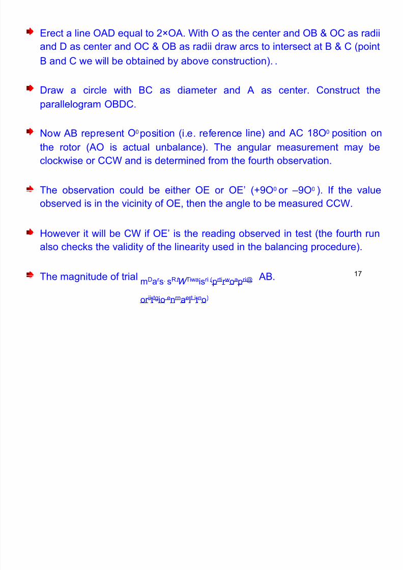
Brect a line ;9D eual to +C;9. ith ; as the center and ;0 ? ;5 as radii
and D as center and ;5 ? ;0 as radii draw arcs to intersect at 0 ? 5 (point
0 and 5 we will be obtained by above construction). .
Draw a circle with 05 as diameter and 9 as center. 5onstruct the
parallelogram ;0D5.
;3 line) and 95 1;3 position on'ow 90 represent position (i.e. reference
the rotor (9; is actual unbalance). The angular measurement may be
cloc8wise or 55 and is determined from the fourth observation.
The observation could be either ;B or ;BE (42;3
observed is in the vicinity of ;B, then the angle to be
or F2;3 ). f the value
measured 55.
>owever it will be 5 if ;BE is the reading observed in test (the fourth run
also chec8s the validity of the linearity used in the balancing procedure).
mDar s. sR.W Tiwaisri (prtir woapri@
or iittgio.enrnaelt.itno)
1*The magnitude of trial 90.t
Page 18
8/18/2019 Docslide.us tggg Balancing of Rotors Ppt
http://slidepdf.com/reader/full/docslideus-tggg-balancing-of-rotors-ppt 18/60
The unbalance ;9 can be obtained accordingly in the mass term. The
∠OABlocation of unbalance is
55).
and the direction from figure (i.e. 5 or
The test is repeated by ma8ing
plane .
the cradle fulcrum bed at #and
measurements are made in
This procedure is very time
of the rotor.
consuming and also restricts the mass and siGe
7odern balancing machines use amplitude and phase measurement
planes for balancing a rotor.
in two
7achines are either soft support or hard support machines.
Dr. R. Tiwari ([email protected] ) 1
Page 19
8/18/2019 Docslide.us tggg Balancing of Rotors Ppt
http://slidepdf.com/reader/full/docslideus-tggg-balancing-of-rotors-ppt 19/60
2;;
2;;2;;
E 4ve 4ve
180 ; ;
;
180 ; ;
;
A
B E B;;
2;;
+*;;
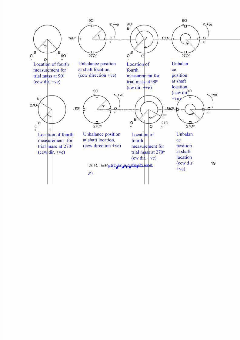
Unbalance position
at shaft location,
(ccw direction +ve)
;;
+*;;
Unbalan
ce
position
at shaft
location
(ccw dir.
+ve)
OO
Location of fourth
measurement for
trial mass at 900
(ccw dir. +ve)
Location of
fourth
measurement for
trial mass at 900
(cw dir. +ve)2;;
2;;4ve 4ve
E’
+*;;
180 ; ;;
180 ; ;;
E’
+*;;
B;;
B
;;
+*;;
Unbalance position
at shaft location,
(ccw direction +ve)
+*;;
Unbalan
ce
position
at shaft
location
(ccw dir.
+ve)
OO
Location of fourth
measurement for
trial mass at 200
(ccw dir. +ve)
Location of
fourth
measurement for
trial mass at 200
(cw dir. +ve)
Dr. R. Tiwari
F
(r
i
t
$
iw
!
a
r
r
e
i@
*
iitg.ernet.
in)
12
Page 20
8/18/2019 Docslide.us tggg Balancing of Rotors Ppt
http://slidepdf.com/reader/full/docslideus-tggg-balancing-of-rotors-ppt 20/60
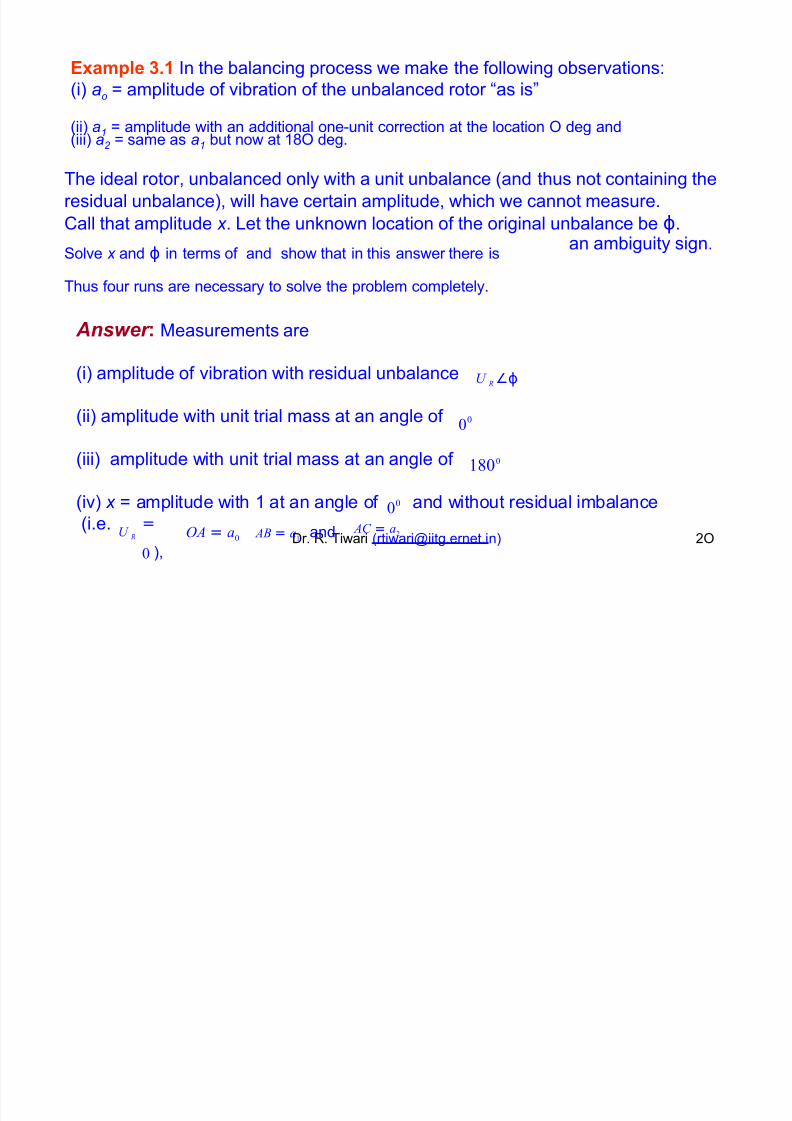
+,am"#e )-% n the balancing process we ma8e the following observations-
(i) ao : amplitude of vibration of the unbalanced rotor Has isI
(ii) a1 : amplitude with an additional one"unit correction at the location ; deg and
(iii) a2 : same as a1 but now at 1; deg.
The ideal rotor, unbalanced only with a unit unbalance (and thus not containing the
residual unbalance), will have certain amplitude, which we cannot measure.
5all that amplitude x . =et the un8nown location of the original unbalance be ϕ.
olve x and ϕ in terms of and show that in this answer there is
Thus four runs are necessary to solve the problem completely.
an ambiguity sign.
Answer . 7easurements are
U R ∠ϕ(i) amplitude of vibration with residual unbalance
00
!800
(ii) amplitude with unit trial mass at an angle of
(iii) amplitude with unit trial mass at an angle of
00(iv) x : amplitude with 1 at an angle of and without residual imbalance
(i.e. =
0 ),
AB = a!and AC = a2OA = a0
U R Dr. R. Tiwari ([email protected] ) +;
Page 21
8/18/2019 Docslide.us tggg Balancing of Rotors Ppt
http://slidepdf.com/reader/full/docslideus-tggg-balancing-of-rotors-ppt 21/60
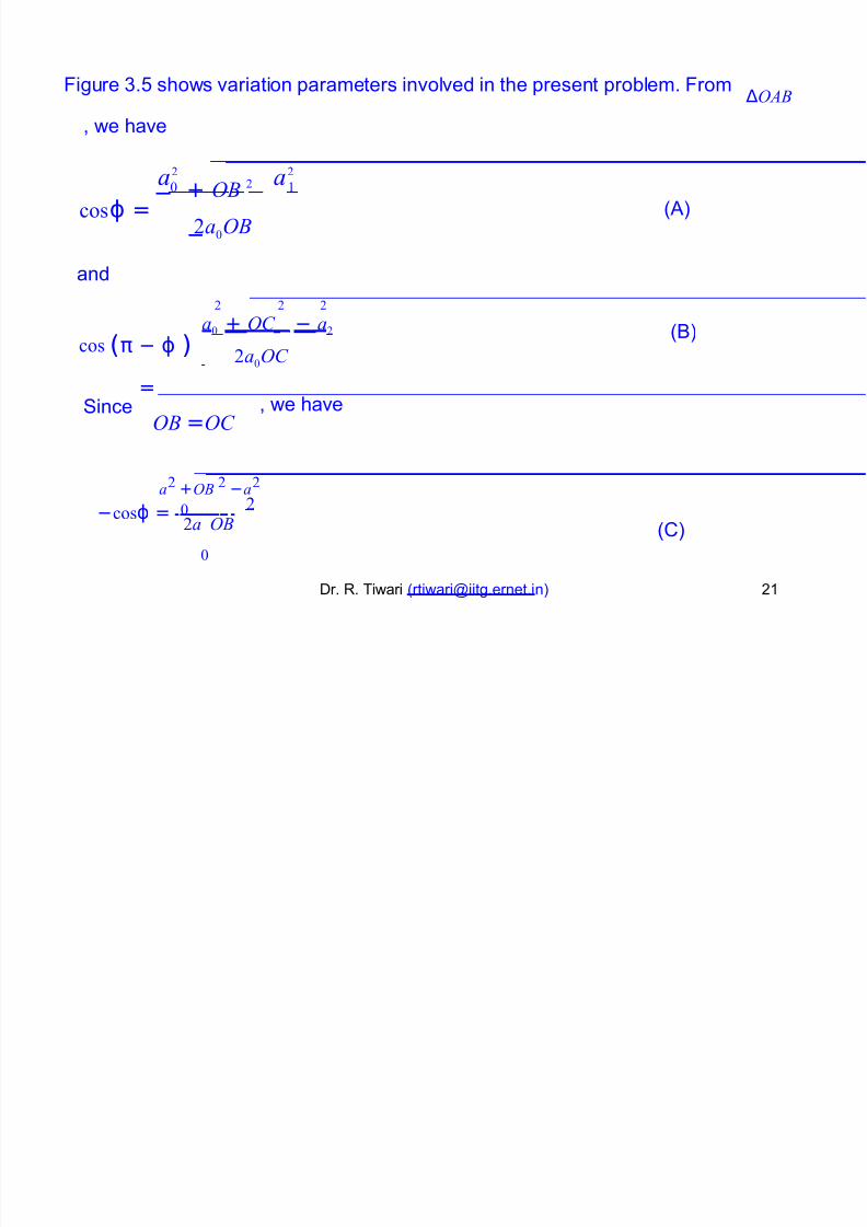
#igure .% shows variation parameters involved in the present problem. #rom ∆OAB
, we have
a2
+ OB 2
−
a2
0 !
cosϕ = (9)2a0OB
and
2 2 2
a0 + OC − a2
cos (π − ϕ )
=
(0)
2a0OC
, we haveinceOB =OC
a2 +OB 2 −a2
−cosϕ = 0 22a OB
0
(5)
Dr. R. Tiwari ([email protected] ) +1
Page 22
8/18/2019 Docslide.us tggg Balancing of Rotors Ppt
http://slidepdf.com/reader/full/docslideus-tggg-balancing-of-rotors-ppt 22/60
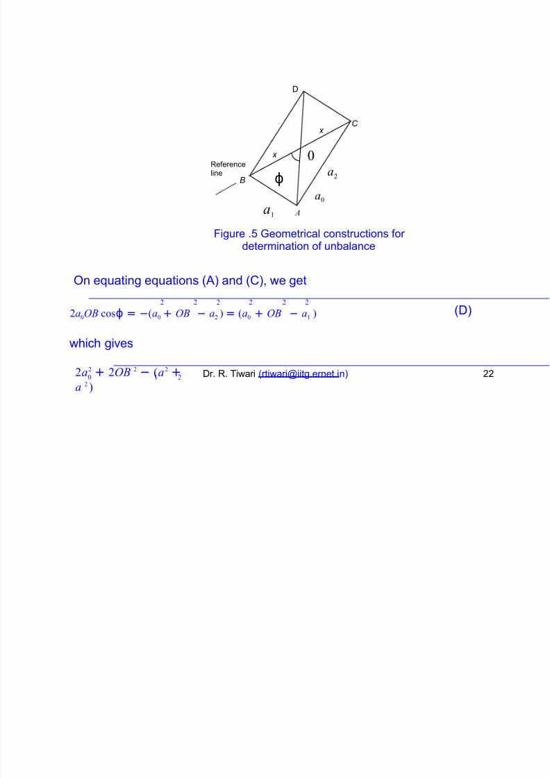
D
C x
0 x
ϕ
a!
a2
Referenceline
B
a0
A
#igure .% Jeometrical constructions for determination of unbalance
;n euating euations (9) and (5), we get
2 2 2 2 2 2
2a0OB cosϕ = −(a0 + OB − a2 ) = (a0 + OB − a! ) (D)
which gives
2a2 + 2OB 2 − (a2 +
a 2 )
Dr. R. Tiwari ([email protected] ) ++0 ! 2
Page 23
8/18/2019 Docslide.us tggg Balancing of Rotors Ppt
http://slidepdf.com/reader/full/docslideus-tggg-balancing-of-rotors-ppt 23/60
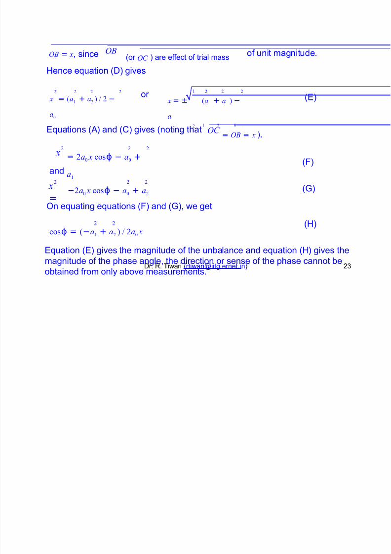
OB = x, since OB(or OC ) are effect of trial mass
of unit magnitude.
>ence euation (D) gives
! 2 2 22 2 2 2 or x = (a
! + a2) " 2 −
a0
x = ± (a + a ) −
a
2 ! 2 0
(B)
Buations (9) and (5) gives (noting that
= OB = x ),
OC
2 2 2
= 2a0 x cosϕ − a0 +
a!
x(#)
and
x
=
2 2 2
−2a0 x cosϕ − a0 + a2(J)
;n euating euations (#) and (J), we get
(>)2 2
cosϕ = (−a! + a2 ) " 2a0 x
Buation (B) gives the magnitude of the unbalance and euation (>) gives the
magnitude of the phase angle, the dir ection or sense of the phase cannot beDr. R. Tiwari ([email protected] ) +
obtained from only above measurements.
Page 24
8/18/2019 Docslide.us tggg Balancing of Rotors Ppt
http://slidepdf.com/reader/full/docslideus-tggg-balancing-of-rotors-ppt 24/60
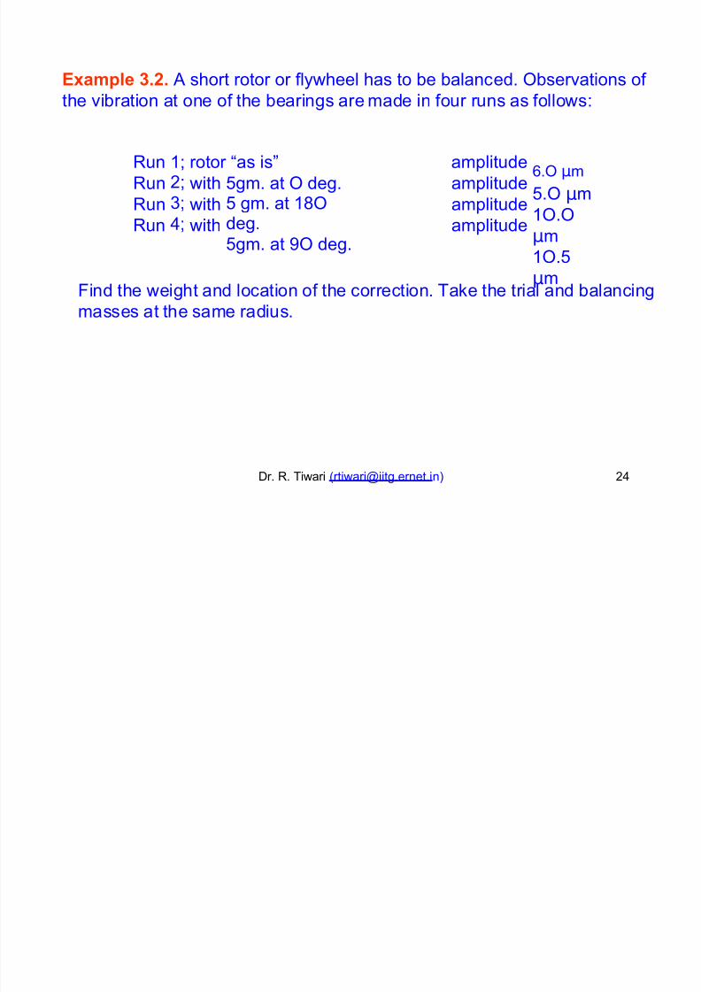
+,am"#e )-'- 9 short rotor or flywheel has to be balanced. ;bservations of
the vibration at one of the bearings are made in four runs as follows-
Run
Run
Run
Run
1K+K
K
/K
rotor Has isI amplitude
amplitude
amplitude
amplitude
.; µm
%.; µm
1;.;
µm
1;.%
µm
with
with
with
%gm. at ; deg.% gm. at 1;deg.
%gm. at 2; deg.
#ind the weight and location of the correction. Ta8e the trial and balancing
masses at the same radius.
Dr. R. Tiwari ([email protected] ) +/
Page 25
8/18/2019 Docslide.us tggg Balancing of Rotors Ppt
http://slidepdf.com/reader/full/docslideus-tggg-balancing-of-rotors-ppt 25/60
B D
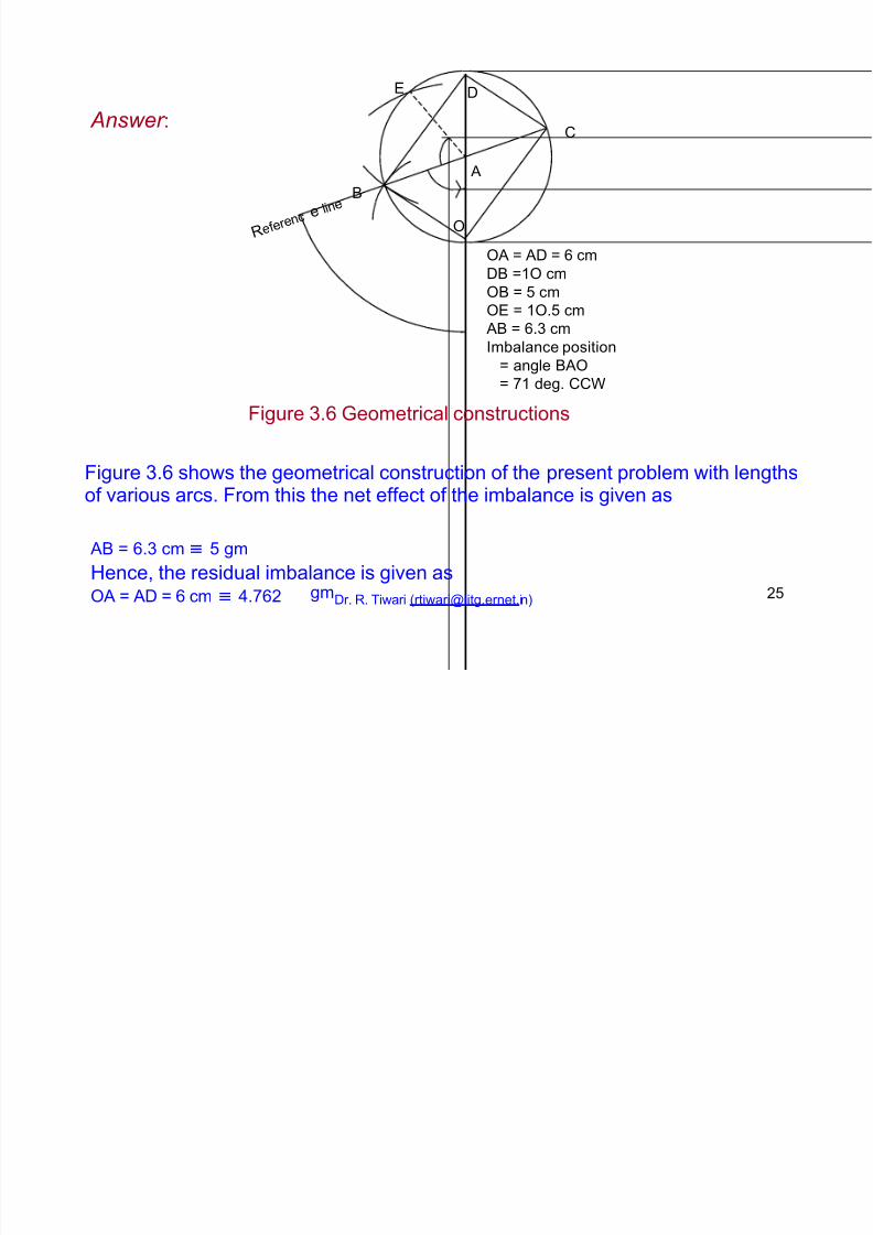
Answer -5
9
0
;
;9 : 9D : cm
D0 :1; cm
;0 : % cm
;B : 1;.% cm 90 : . cm
mbalance position
: angle 09;
: *1 deg. 55
#igure . Jeometrical constructions
#igure . shows the geometrical construction of the present problem with lengthsof various arcs. #rom this the net effect of the imbalance is given as
90 : . cm ≡ % gm
>ence, the residual imbalance is given as;9 : 9D : cm ≡ /.*+ gmDr. R. Tiwari ([email protected] ) +%
R e f e r e
n c e l i n
e
Page 26
8/18/2019 Docslide.us tggg Balancing of Rotors Ppt
http://slidepdf.com/reader/full/docslideus-tggg-balancing-of-rotors-ppt 26/60
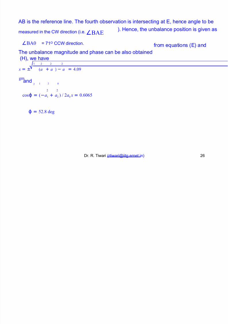
90 is the reference line. The fourth observation is intersecting at B, hence angle to be
measured in the 5 direction (i.e.∠#$%
∠#$0 : *1; 55 direction.
The unbalance magnitude and phase can be also obtained
(>), we have
). >ence, the unbalance position is given as
from euations (B) and
! 2 2 2
x = ± (a + a ) − a = &.09
'm
2 ! 2 0and
2 2
cosϕ = (−a! + a2 ) " 2a0 x = 0.0
ϕ = 2.8 de'
Dr. R. Tiwari ([email protected] ) +
Page 27
8/18/2019 Docslide.us tggg Balancing of Rotors Ppt
http://slidepdf.com/reader/full/docslideus-tggg-balancing-of-rotors-ppt 27/60
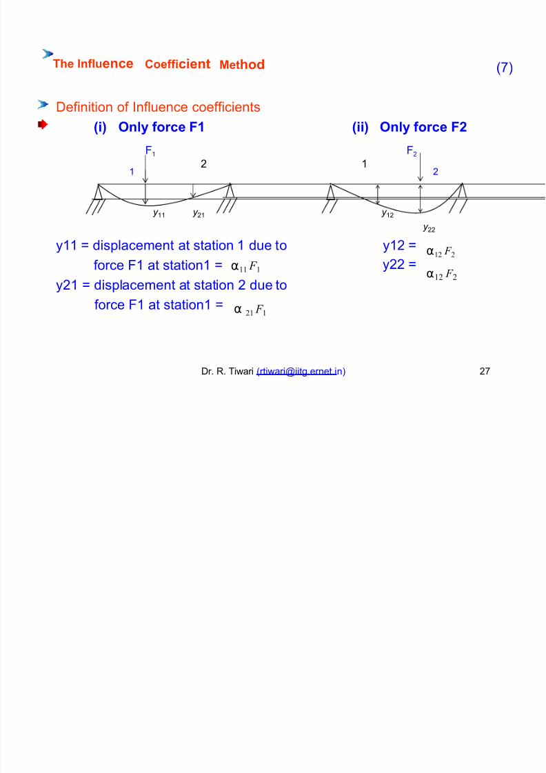
The Inf#!ence Coefficient Metho (*)
Definition of nfluence coefficients
/i0 On#y force
#1
1
F% /ii0 On#y force F'
#+
++ 1
y 11 y +1 y 1+
y ++
α!2 F 2
α!2 F 2
y11 : displacement at station 1 due to y1+
y++
:
:α!! F !force #1 at station1 :
y+1 : displacement at station + due toα 2! F !
force #1 at station1 :
Dr. R. Tiwari ([email protected] ) +*
Page 28
8/18/2019 Docslide.us tggg Balancing of Rotors Ppt
http://slidepdf.com/reader/full/docslideus-tggg-balancing-of-rotors-ppt 28/60
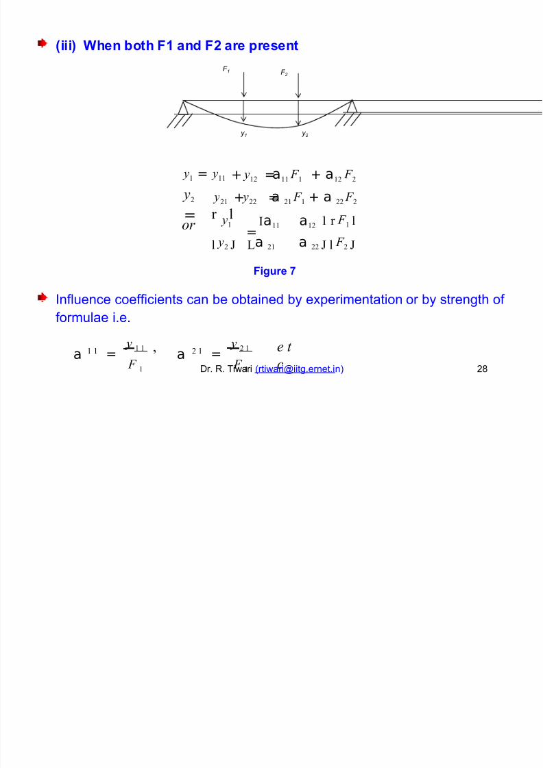
/iii0 1hen oth F% an F' are "resent
F 1 F 2
y 1 y 2
y!2 a!! F ! + a!2 F 2 y! =
y2
=
y!! + =
y2! y22 a 2! F ! + a 22 F 2+ =
*a!! a!2 y! ! r F ! l
r lor
=l y2 La 2!
Fi$!re 2
a 22 l F 2
nfluence coefficients can be obtained by e!perimentation
formulae i.e.
or by strength of
y ! ! y 2 !a a=
,=
e t
c .! ! 2 !
F ! F !Dr. R. Tiwari ([email protected] ) +
Page 29
8/18/2019 Docslide.us tggg Balancing of Rotors Ppt
http://slidepdf.com/reader/full/docslideus-tggg-balancing-of-rotors-ppt 29/60
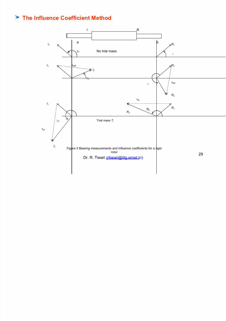
The Inf#!ence Coefficient Metho
l R
l 1 R 1
1'o trial mass
l 1 R 1
l 2
2
abR
R 2
abl
l 1
R 1
R 3
3 Trial mass T l
aal
l 3#igure % 0earing measurements and influence coefficients for a rigid
rotor
Dr. R. Tiwari ([email protected] )
+2
b
2
#
a
1
aaR
Page 30
8/18/2019 Docslide.us tggg Balancing of Rotors Ppt
http://slidepdf.com/reader/full/docslideus-tggg-balancing-of-rotors-ppt 30/60
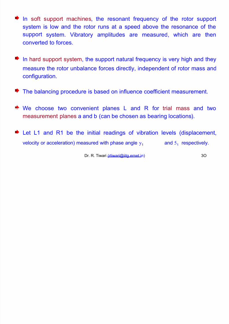
n soft support machines, the resonant freuency of the rotor support
system
support
is low and the rotor runs at a speed above the resonance of the
system. Libratory amplitudes are measured, which are then
converted to forces.
n hard support system, the support natural freuency is very high and they
measure the rotor unbalance forces directly, independent of rotor mass and
configuration.
The balancing procedure is based on influence coefficient measurement.
e choose two convenient planes = and R for trial mass and two
measurement planes a and b (can be chosen as bearing locations).
=et =1 and R1 be the initial readings of vibration levels (displacement,
velocity or acceleration) measured with phase angle 1 and 1 respectively.
Dr. R. Tiwari ([email protected] ) ;
Page 31
8/18/2019 Docslide.us tggg Balancing of Rotors Ppt
http://slidepdf.com/reader/full/docslideus-tggg-balancing-of-rotors-ppt 31/60
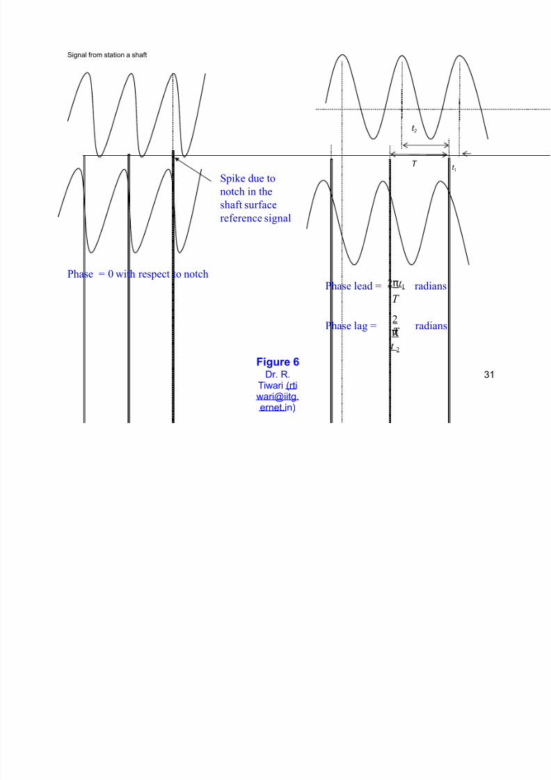
ignal from station a shaft
T t 1
-pie due to
notch in theshaft surface
reference si'nal
/hase 0 with respect to notch2πt !
T
2
πt 2
/hase lead radians
/hase la' radiansT
Fi$!re 3Dr. R.
Tiwari ([email protected] )
1
t 2
Page 32
8/18/2019 Docslide.us tggg Balancing of Rotors Ppt
http://slidepdf.com/reader/full/docslideus-tggg-balancing-of-rotors-ppt 32/60
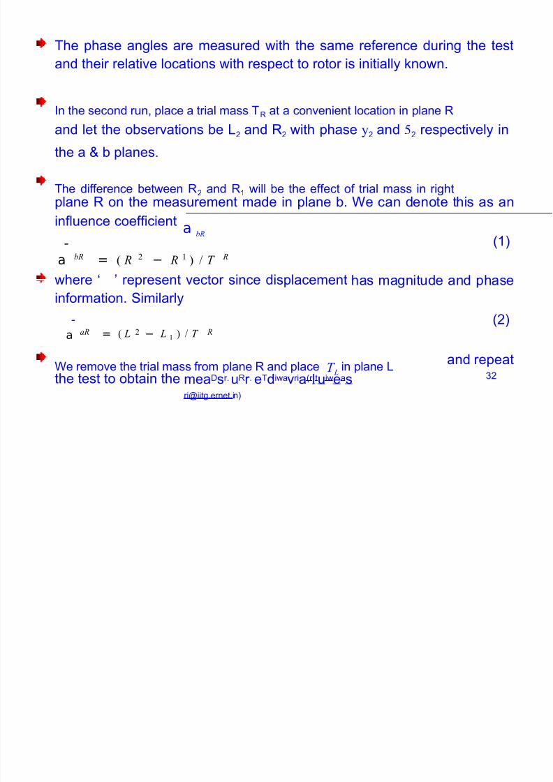
The phase angles are measured with the same reference during the test
and their relative locations with respect to rotor is initially 8nown.
n the second run, place a trial mass TR at a convenient location in plane R
and let the observations be =+ and R+ with phase + and + respectively in
the a ? b planes.
The difference between R+
and R1
will be the effect of trial mass in rightplane R on the measurement made in plane b.
a bR
e can denote this as an
influence coefficient
(1)1
a = ( R − R ) " T bR 2 ! R
where M E represent vector since displacement
information. imilarly
1
has magnitude and phase
(+)a = ( L − L ! ) " T aR 2 R
e remove the trial mass from plane R and place T L in plane =and repeat
+meaDsr. uRr . eTdiwavria(r [email protected] )
the test to obtain the
Page 33
8/18/2019 Docslide.us tggg Balancing of Rotors Ppt
http://slidepdf.com/reader/full/docslideus-tggg-balancing-of-rotors-ppt 33/60
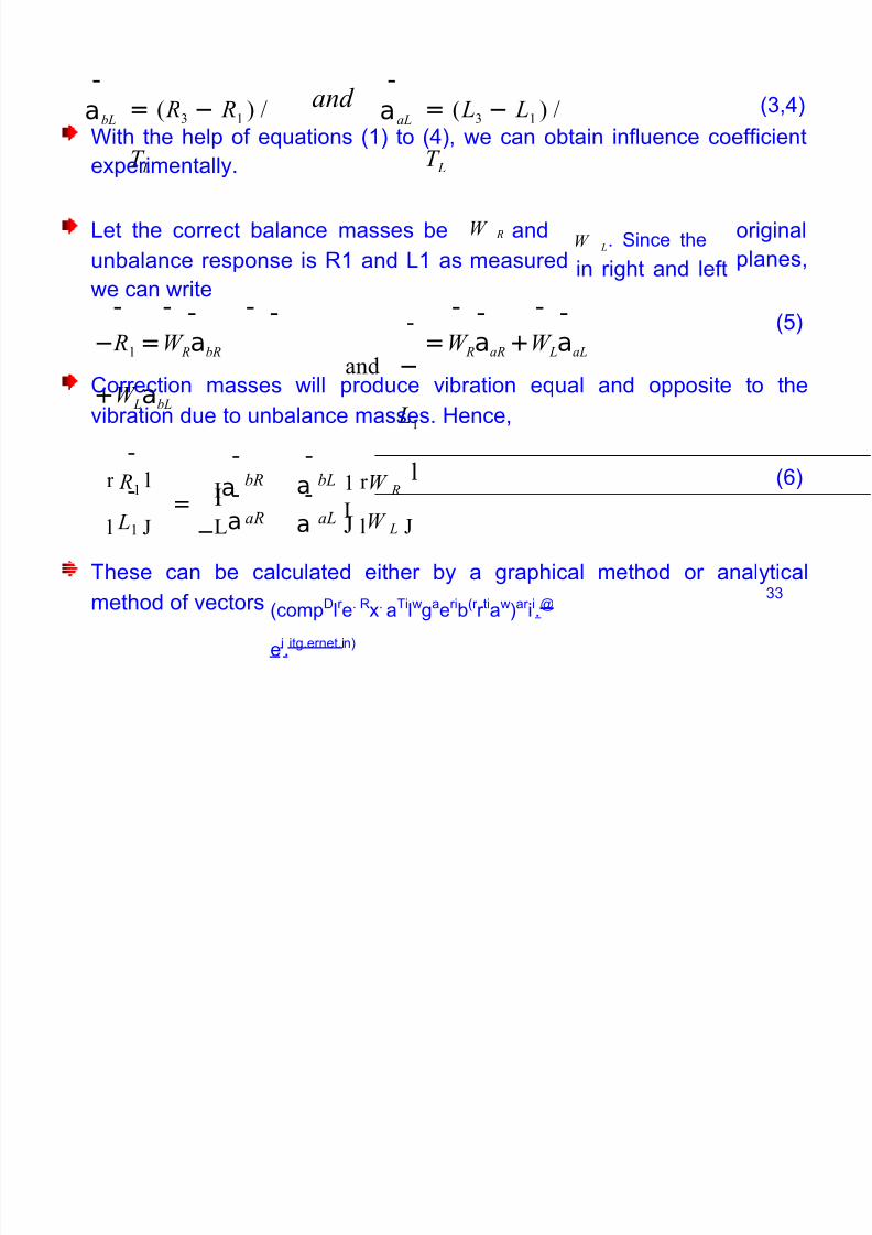
1 1
abL aaL= ( R − R! ) "
T L
and = ( L − L! ) "
T L
(,/)
ith the help of euations (1) to
e!perimentally.
(/), we can obtain influence coefficient
W =et the correct balance masses be andW L. ince the
in right and left
original
planes,
R
unbalance response is R1 and =1 as
we can write
measured
1 1 1 1
and −
L!
1 11 1 1 1 (%)− R! =W RabR
+W LabL
=W RaaR +W LaaL
5orrection masses will produce vibration eual and opposite to the
vibration due to unbalance masses. >ence,
1 1 1r R!l
*a
−
a ! r W Rl ()bR bL
1= 1 1
**La a lW L l L!
aR aL
These can be calculated either by a graphical method or analytical
(compD
lr
e. R
!.
aTi
lw
ga
eri
b(r
r ti
aw
)ar
ii
.@
ei.itg.ernet.in)
method of vectors
Page 34
8/18/2019 Docslide.us tggg Balancing of Rotors Ppt
http://slidepdf.com/reader/full/docslideus-tggg-balancing-of-rotors-ppt 34/60
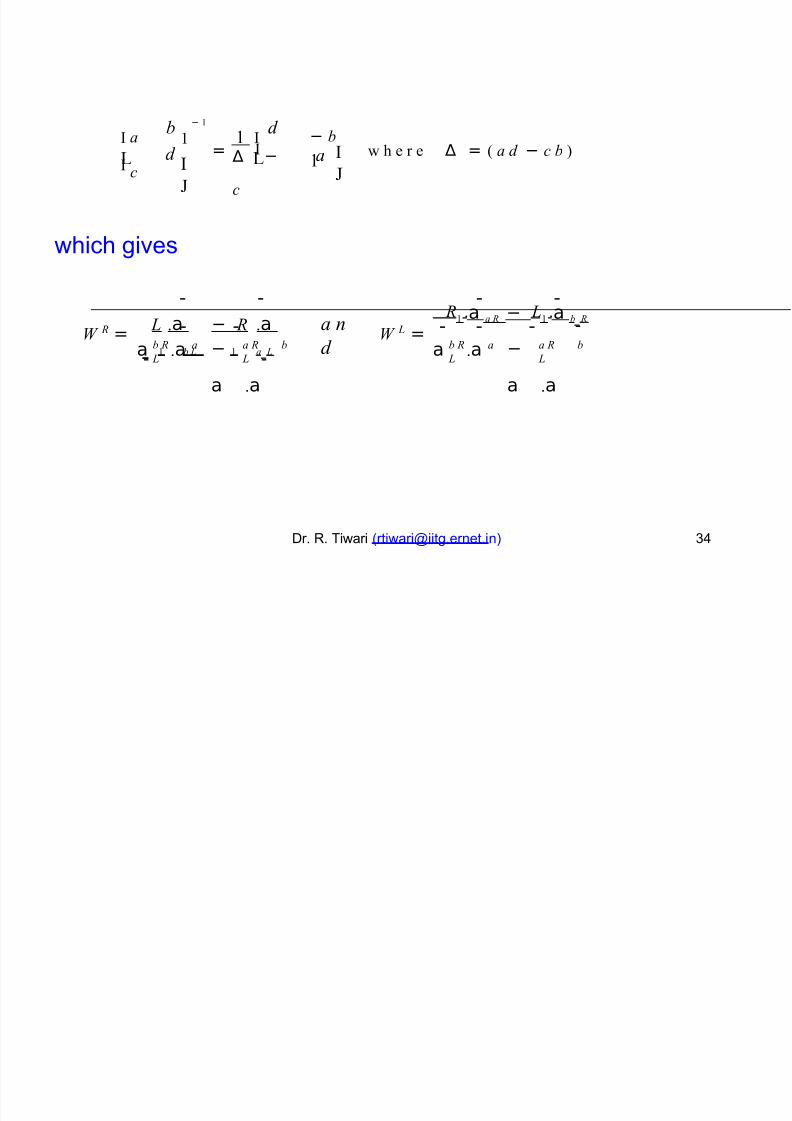
− !
* a* c
b
d
d
− b!
!*
! *= w h e r e ∆ = ( a d − c b ) ∆ * −
c
*
aL L
which gives
1 1 1 1
L .a − R .a
1! b L ! a
1 L
R!.a a R − L
!.a b
1 R
W =a n
d W =1 1 1 1 1 R L
a .a −
a .a
a .a −
a .a
b R a
L
a R b
L
b R a
L
a R b
L
Dr. R. Tiwari ([email protected] ) /
Page 35
8/18/2019 Docslide.us tggg Balancing of Rotors Ppt
http://slidepdf.com/reader/full/docslideus-tggg-balancing-of-rotors-ppt 35/60
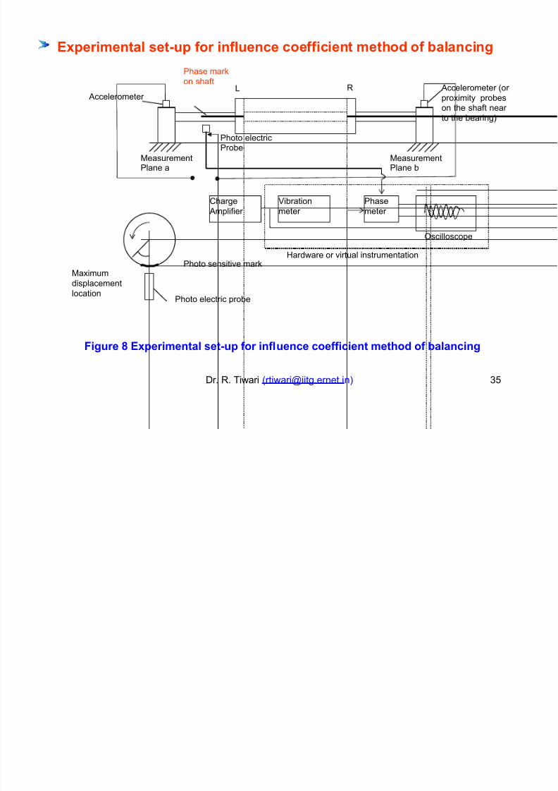
+,"erimenta# set4!" for inf#!ence
hase mar8
on shaft
coefficient metho of a#ancin$
R 9ccelerometer (or
pro!imity probeson the shaft near
to the bearing)
= 9ccelerometer
7easurementlane a
7easurementlane b
>ardware or virtual instrumentationhoto sensitive mar8
7a!imum
displacement
location hoto electric probe
Fi$!re 5 +,"erimenta# set4!" for inf#!ence coefficient metho of a#ancin$
Dr. R. Tiwari ([email protected] ) %
5harge 9mplifier
Librationmeter
hasemeter
;scilloscope
hoto electricrobe
Page 36
8/18/2019 Docslide.us tggg Balancing of Rotors Ppt
http://slidepdf.com/reader/full/docslideus-tggg-balancing-of-rotors-ppt 36/60
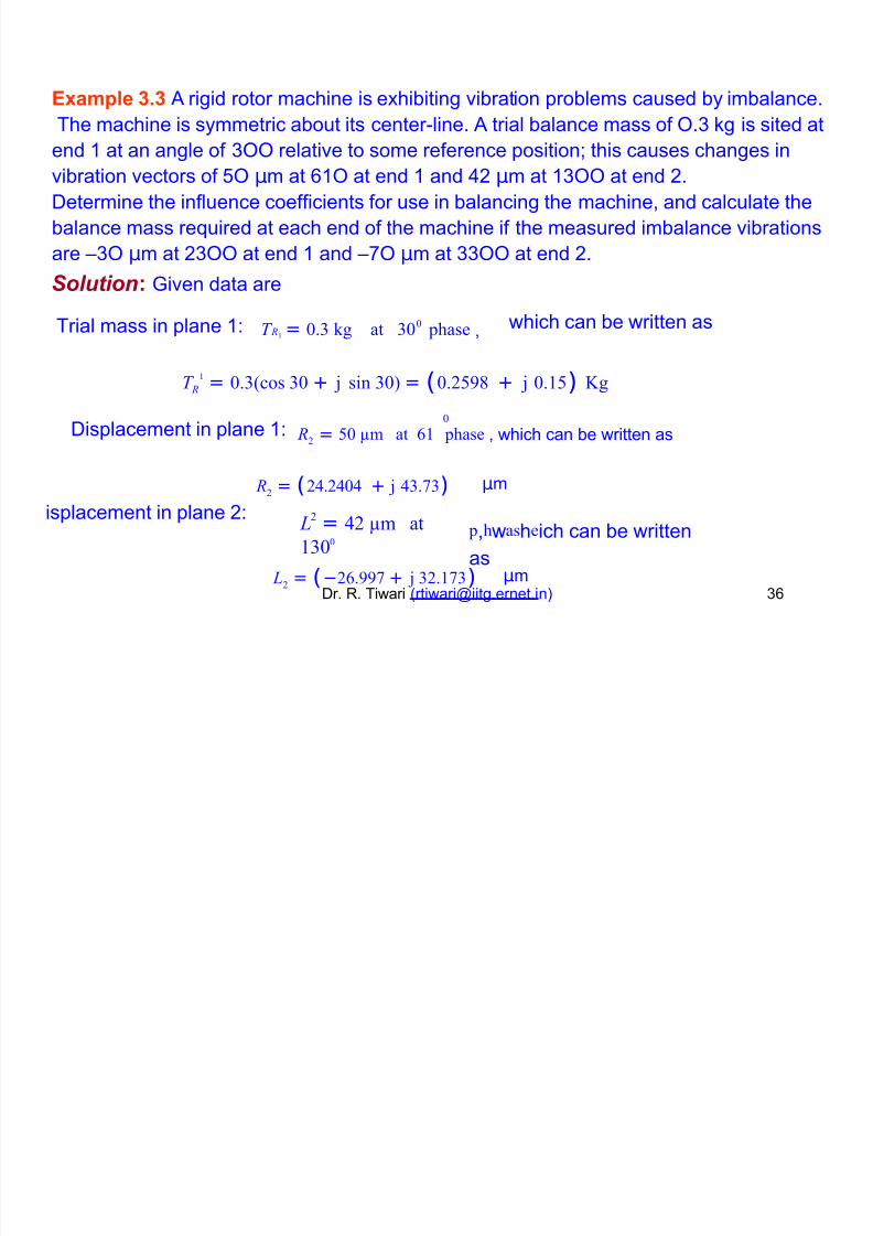
+,am"#e )-) 9 rigid rotor machine is e!hibiting vibration problems caused by imbalance.
The machine is symmetric about its center"line. 9 trial balance mass of ;. 8g is sited at
end 1 at an angle of ;; relative to some reference positionK this causes changes invibration vectors of %; µm at 1; at end 1 and /+ µm at 1;; at end +.
Determine the influence coefficients for use in balancing the machine, and calculate the
balance mass reuired at each end of the machine if the measured imbalance vibrations
are F; µm at +;; at end 1 and F*; µm at ;; at end +.
Solution. Jiven data are
T = 0. ' at 00 phase , which can be written asTrial mass in plane 1- R!
T R = 0.(cos 0 + 3 sin 0) = (0.298 + 3 0.!) 4'!
0
R2 = 0 5m at ! phase , which can be written asDisplacement in plane 1-
R2 = (2&.2&0& + 3 &.)
L = &2 5m at
!00
µm
p,hwasheich can be written
as
isplacement in plane +- 2
L2= (−2.99 + 3 2.!) µm
Dr. R. Tiwari ([email protected] )
Page 37
8/18/2019 Docslide.us tggg Balancing of Rotors Ppt
http://slidepdf.com/reader/full/docslideus-tggg-balancing-of-rotors-ppt 37/60
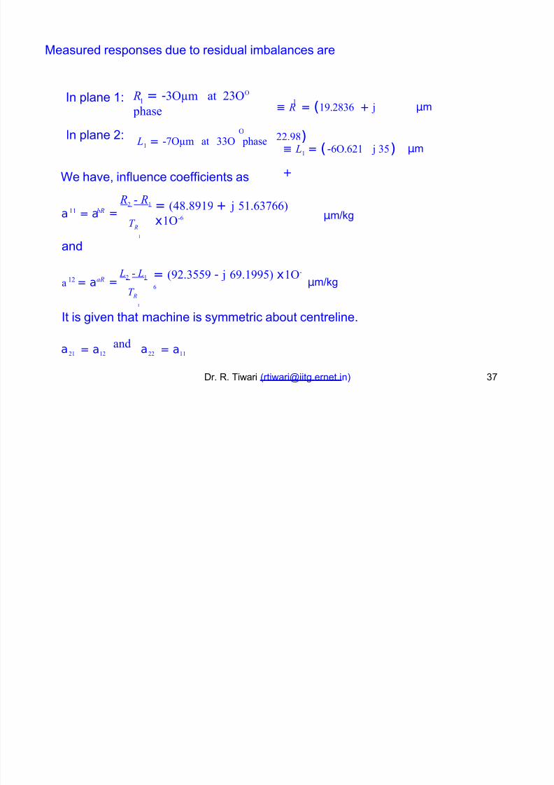
7easured responses due to residual imbalances are
R = -65m at 26
6
phase ≡ R = (!9.28 + 3
22.98)
n plane 1- µm! !
6n plane +- L
! = -65m at 6 phase≡ L
! = (-6.2!
+
3 ) µm
e have, influence coefficients as
R2 1 R! = (&8.89!9 + 3 !.)
x!6-a = a = µmN8g
!! bR
T R!
and
L2 1 L! = (92.9 - 3 9.!99) x!6-
a = a µmN8g=!2 aR
T R!
t is given that machine is symmetric about centreline.
a2! = a!2 a22 = a!!
and
Dr. R. Tiwari ([email protected] ) *
Page 38
8/18/2019 Docslide.us tggg Balancing of Rotors Ppt
http://slidepdf.com/reader/full/docslideus-tggg-balancing-of-rotors-ppt 38/60
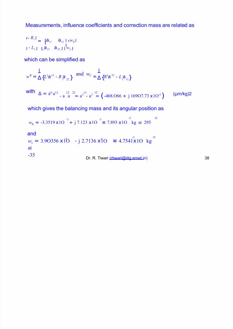
7easurements, influence coefficients and correction mass are related as
*a!! a!2 ! r w R l
r - R! l
= **l - L! La2! a22 l w L
which can be simplified as
!
∆
!
∆{ ! 22 } { ! !!} L a - R a R a - L aw =and w
= R ! !2 L ! 2!
- a a = a2 - a2 = (-&8.6 + 3 !96. x!6-) ∆ = a a (µmN8g)+with !! !2 !2 22 !! !2
which gives the balancing mass and its angular position as
- -1 6
w7 = -.!9 x!6 + 3 .!2 x!6 ≡ .89 x!6 ' at 29
and
wL = .96 x!6 - 3 2.! x!6 ≡ &.&!x!6 '
at
1
- -1 6
Dr. R. Tiwari ([email protected] )
Page 39
8/18/2019 Docslide.us tggg Balancing of Rotors Ppt
http://slidepdf.com/reader/full/docslideus-tggg-balancing-of-rotors-ppt 39/60
Ba#ancin$ of F#e,i#e Rotors .
9s long as the rotor e!periences no deformations i.e. it remains as a
rigid rotor, the balancing procedure discussed earlier is effective.
;nce the rotor bends while approaching a critical speed, the bend center
line whirls around and additional centrifugal forces are set"up and the rigid
rotor balancing becomes ineffective. (sometimes rigid rotor balancing
worsens bending mode whirl amplitude).
Two different techniues are generally employed
(i) 7odal balancing techniue. 0ishop, Jladwell ? ar8insonand
(ii) nfluence coefficient method. Tessarri8, 0adgley and Rieger.
Moa# a#ancin$ metho
9 practical procedure to balance the rotor by model correction, masses
eual in number to the fle!ible mode shapes, ', 8nown as '"plane
method.Dr. R. Tiwari ([email protected] ) 2
Page 40
8/18/2019 Docslide.us tggg Balancing of Rotors Ppt
http://slidepdf.com/reader/full/docslideus-tggg-balancing-of-rotors-ppt 40/60
Run the rotor in a suitable hard bearing balancing machine, to a safe speed
approaching the first critical speed and record the bearing vibrations
forces.
or
5hoose an appropriate location for the trial mass.
#or first critical speed, this should be roughly in the middle for a
a
t
symmetrical rotor in its a!ial distribution of mass. Record the readings
the same speed as before.
6sing the above two readings, the correct mass and location can be
determined. (single plane balancing). ith this correction mass, it should be
possible to run the rotor through the first critical speed without appreciable
vibration.
'e!t, run the rotor to a safe speed approaching the second critical speed, if
the operating speed is near the second critical or above the second criticalDr. R. Tiwari ([email protected] ) /;speed.
Page 41
8/18/2019 Docslide.us tggg Balancing of Rotors Ppt
http://slidepdf.com/reader/full/docslideus-tggg-balancing-of-rotors-ppt 41/60
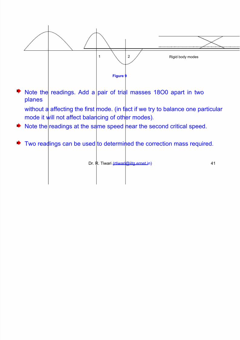
Rigid body modes
Fi$!re 6
'ote the readings. 9dd a pair of trial masses 1;3 apart in two
planes
without a affecting the first mode. (in fact if we try to balance one particular
mode it will not affect balancing of other modes).
'ote the readings at the same speed near the second critical speed.
Two readings can be used to determined the correction mass reuired.
Dr. R. Tiwari ([email protected] ) /1
1 +
Page 42
8/18/2019 Docslide.us tggg Balancing of Rotors Ppt
http://slidepdf.com/reader/full/docslideus-tggg-balancing-of-rotors-ppt 42/60
'thimilarly higher modes can be balanced i.e. up
of
to
'
mode can be
balanced by ' balancing planes. nstead plane correction,
Oellenberger suggested that the rotor should
so as not to disturb the rigid body balancing.
be corrected in '4+ planes,
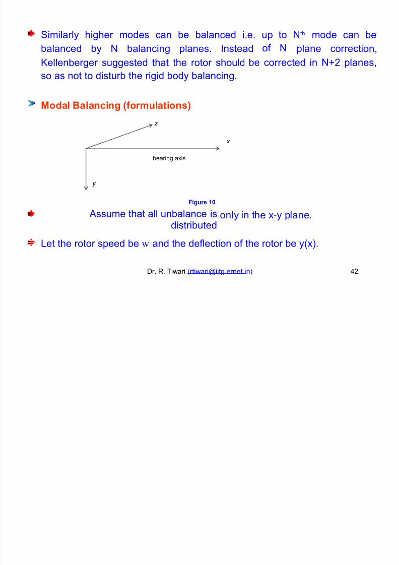
Moa# Ba#ancin$ /form!#ations0
z
x
bearing a!is
y
Fi$!re %7
9ssume that all unbalance isdistributed
only in the !"y plane.
=et the rotor speed be w and the deflection of the rotor be y(!).
Dr. R. Tiwari ([email protected] ) /+
Page 43
8/18/2019 Docslide.us tggg Balancing of Rotors Ppt
http://slidepdf.com/reader/full/docslideus-tggg-balancing-of-rotors-ppt 43/60
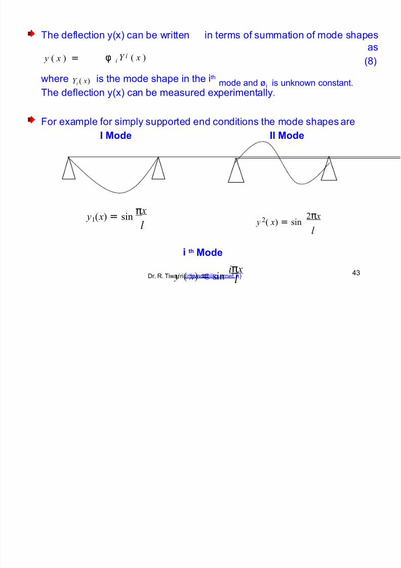
The deflection y(!) can be written in terms of summation of mode shapes
as
()φ i Y ( x ) y ( x ) = i
Y i ( x) ithwhere is the mode shape in the mode and Pi is un8nown constant.The deflection y(!) can be measured e!perimentally.
#or e!ample for simply
I Moe
supported end conditions the mode shapes
II Moe
are
y ( x) = sin π x 2π x
l y ( x) = sin! 2
l
i th Moe
iπ x y ( x) = sinDr. R. Tiwairi ([email protected] )
/
l
Page 44
8/18/2019 Docslide.us tggg Balancing of Rotors Ppt
http://slidepdf.com/reader/full/docslideus-tggg-balancing-of-rotors-ppt 44/60
#or other end conditions mode shapes can be obtained by free vibration
analysis. 7odal series for eccentricity can also be written as
a( x) = La i Y i ( x)
i
(2)
t can be written in terms of mode summation since the y ( x ) is the result of
a( x ). The main obQective is to find out for the eccentricity distribution to be
8nown.
7ultiplying () by the mass per unit length m(!) and the mode shape
Y j( x)
l
and integrate from ; to
1.
l * !
m( x) y( x)Y j ( x) = m( x)*LφiY i ( x)*Y j ( x)dx
(1;
)L
i
6 6
noting the orthogonality condition of mode shapes
l
6
m ( x)Y i ( x)Y j ( x)dx = 6 for all i ≠ j (11)//Dr. R. Tiwari ([email protected] )
Page 45
8/18/2019 Docslide.us tggg Balancing of Rotors Ppt
http://slidepdf.com/reader/full/docslideus-tggg-balancing-of-rotors-ppt 45/60
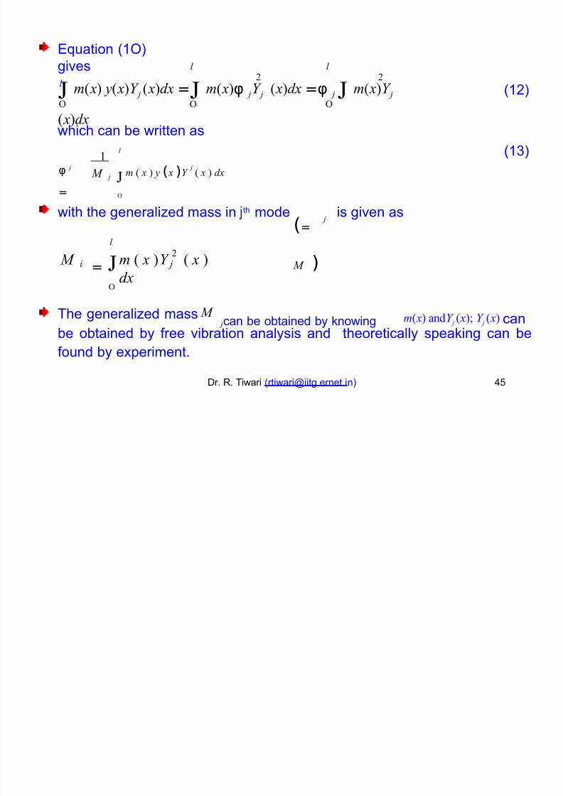
Buation (1;)
givesl
l l 2 2
m( x) y( x)Y j ( x)dx =
m( x)φ jY j ( x)dx =φ j
m( x)Y j
( x)dx
(1+)6 6 6
which can be written as
(1)l
6
!
m ( x ) y ( x )Y ( x ) dxφ
=
j j M j
(=
M )
Qthwith the generaliGed mass in mode is given as j
l
6
2 M
=m ( x )Y ( x )
dxi j
m( x) andY j ( x) Y j ( x) can M The generaliGed mass jcan be obtained by 8nowing
be obtained by free vibration analysis and
found by e!periment.
theoretically spea8ing can be
Dr. R. Tiwari ([email protected] ) /%
Page 46
8/18/2019 Docslide.us tggg Balancing of Rotors Ppt
http://slidepdf.com/reader/full/docslideus-tggg-balancing-of-rotors-ppt 46/60
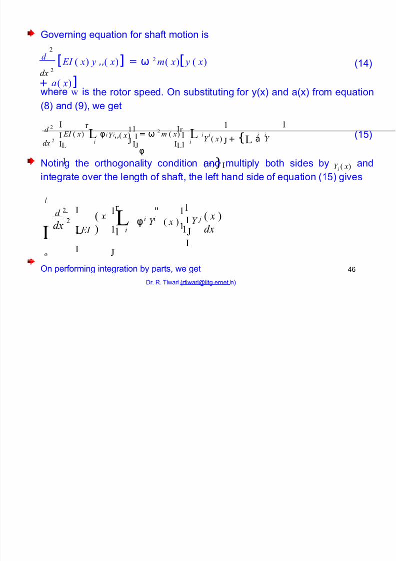
Joverning euation for shaft motion is
d [ E ( x) y ,,( x)] = ω 2 m( x)[ y ( x)
+ a( x)]
2
(1/)
dx 2
where w is the rotor speed. ;n substituting for y(!) and a(!) from euation
() and (2), we get
*!! *r
!d 2 r !
Y ( x) + {L a Y
( x)}*
* E ( x) L φ = ω 2m ( x) * L
φ
Y ,,( x) * (1%)i i i i i i
dx 2 *L
l
* *Ll i i
'oting the orthogonality condition and multiply both sides by Y i ( x) and
integrate over the length of shaft, the left hand side of euation (1%) gives
l
*o
*
* E
*
!!
!
!r "d 2
L * Y φ Y ( x )( x
)
( x )
dx
*
i i j2dx !l !
L i
;n performing integration by parts, we get
Dr. R. Tiwari ([email protected] )
/
Page 47
8/18/2019 Docslide.us tggg Balancing of Rotors Ppt
http://slidepdf.com/reader/full/docslideus-tggg-balancing-of-rotors-ppt 47/60
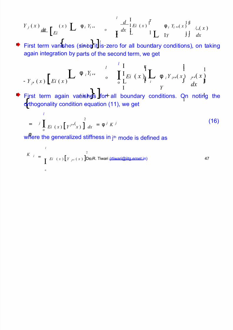
l
*
*! !r
d [ Ei
φ Y ,,
( x ) }]l -
( x )
{
d* Ei ( x )
!φ Y ,,( x )
!
*Y
LL
!
,,( x )
dx
Y ( x ) j i i i i jdx dx *
! *o
l i
Lo
#irst term vanishes
again integration by
(since it is Gero for all boundary conditions), on ta8ing
parts of the second
l
term, we get
*
*!
*
r !
- Y j, ( x ) [ Ei ( x )
{
φ i Y ,,
( x )}] +
! !l
L L* φ i Y i,,( x )
Y
!
j,,( x )
dx
*
Ei
*
( x )io !
li
L o
#irst term again vanishes for all boundary conditions. ;n noting the
orthogonality condition euation (11), we get
l
Ei ( x ) [Y x ) ] dx*2 (1)
=
φ
j,,( = φ ! j j jo
where the generaliGed stiffness in Qth mode is defined as
l
*o
Ei ( x ) [Y j,, ( x ) ] dx
2 !
= jDr. R. Tiwari ([email protected] ) /*
Page 48
8/18/2019 Docslide.us tggg Balancing of Rotors Ppt
http://slidepdf.com/reader/full/docslideus-tggg-balancing-of-rotors-ppt 48/60
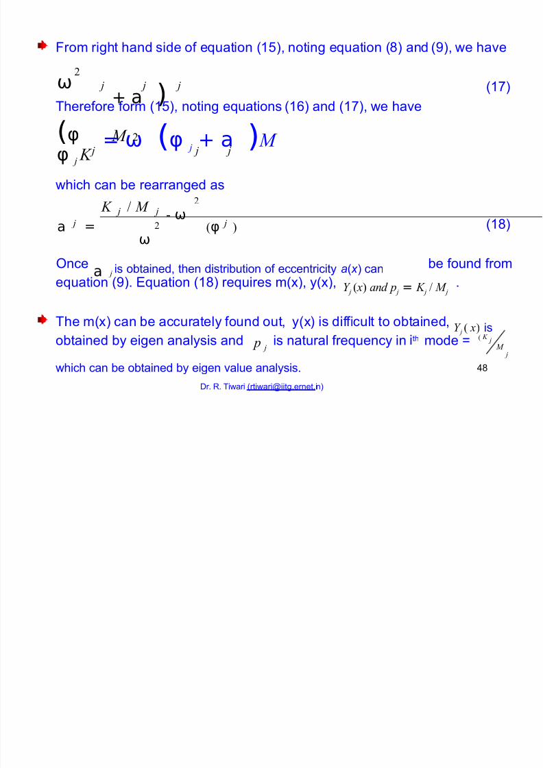
#rom right hand side of euation (1%), noting euation () and (2), we have
ω
(φ
+ a ) M
2
j j j (1*)
Therefore form (1%), noting euations
= ω (φ j + a ) M
(1) and (1*), we have
2
φ j ! j j j
which can be rearranged as2
- ω ! " M j j
a (φ )= (1) j j2
ω
a;nce
j is obtained, then distribution of eccentricity a( x ) can be found from
Y j ( x) and " j = ! j " M jeuation (2). Buation (1) reuires m(!), y(!), .
The m(!) can be accurately found out, y(!) is difficult to obtained, Y j ( x) is
" j
( ! jithobtained by eigen analysis and is natural freuency in mode : M
j
/which can be obtained by eigen value analysis.
Dr. R. Tiwari ([email protected] )
Page 49
8/18/2019 Docslide.us tggg Balancing of Rotors Ppt
http://slidepdf.com/reader/full/docslideus-tggg-balancing-of-rotors-ppt 49/60
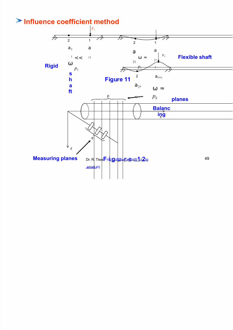
Inf#!ence coefficient methoF 1
+
a2
!
ω
sh
aft
1
a
!!
+
a
2!
1
a
!,
!
,
<<
"!
ω ≈
"!
#1 F#e,i#e shaft
Ri$i
a!,,!
ω ≈
"+
Ba#ancin$
+
a2,
,!
Fi$!re %%
"#anes
x
!
z
Meas!rin$ "#anes Dr. R. TiwaFrii($rt!iwr aeri@%ii'tg
.ernet.in)
/2
Page 50
8/18/2019 Docslide.us tggg Balancing of Rotors Ppt
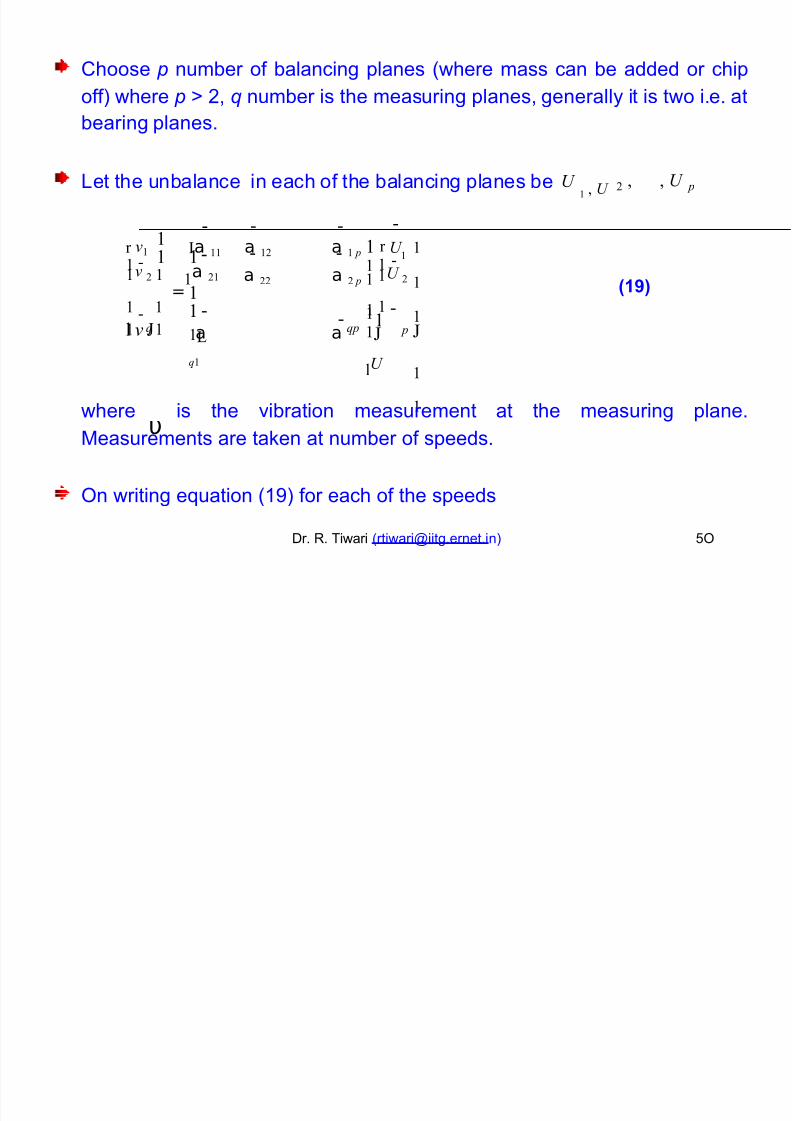
http://slidepdf.com/reader/full/docslideus-tggg-balancing-of-rotors-ppt 50/60
5hoose number of balancing planes (where mass can be added or chip
off) where +, ! number
bearing planes.
is the measuring planes, generally it is two i.e. at
=et the unbalance in each of the balancing planes be , , U U ! , U 2 "
11 1
1
1
1*a !! a !2 a ! " ! r U !
!
!
!
!
r #!!
1 !! 1 1
! !! !!# 2 !
!a 2!
a 22 a 2 "
1
!!U
2=!
/%60!! 1 ! ! ! 11!!# !
!a a !
lU
!L
$!
l $ $" "
υwhere is the vibration measurement at the measuring plane.
7easurements are ta8en at number of speeds.
;n writing euation (12) for each of the speeds
Dr. R. Tiwari ([email protected] ) %;
Page 51
8/18/2019 Docslide.us tggg Balancing of Rotors Ppt
http://slidepdf.com/reader/full/docslideus-tggg-balancing-of-rotors-ppt 51/60
1 1 1 1! ! ! !r
*
*
**
*
*
*
*
**
*
*
*
*
*
*l
l
*
*
**
*
*
*
*
**
*
*
*
*
*
*
. al
*
*
**
*
*
*
*
*
**
*
*
*
*
*
*
a.
.
.
.
.
.
.
a#
1!
1! !
1! 2
1! "
*a
! !
2 !
!
2 2
!
!
2 "a a# *
*
2
1
* 1 1 11
%
! ! !
$ "
2
! "
a a a# *
1$ ! r l
*
*
*
*
1$
1$ 2 1 !
* a1*2 2
! !
2
! 2
2
$2
a a# !
** % 2
1**
*
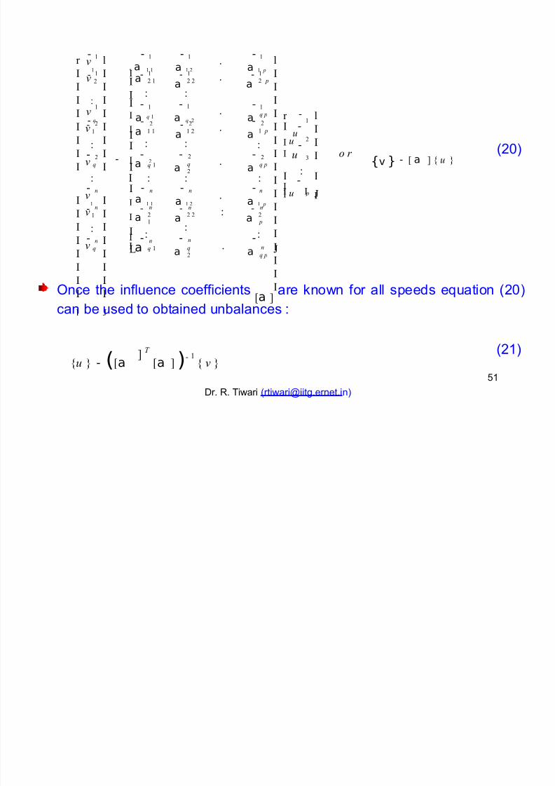
(+3){v } - : a ; < % =-
o r 1 1 1 1 %* a 2
2
$
2
$ "a a
#* $ !
* * *
n
1* % *1 1 11 *n n n
l * a a a# "
1!
1! !
1! 2
1! "
* a
*
n n
2!
n
2 2
n
$2
n
2 "
n
$ "
a a# !
*1 1 1 1
* an
$
n
$ ! a a# L
;nce the influence coefficients :a ; are 8nown for all speeds euation (+3)can be used to obtained unbalances -
<% = - (:a :a ; )- !< # =
Dr. R. Tiwari ([email protected] )
; T (+1)
%1
Page 52
8/18/2019 Docslide.us tggg Balancing of Rotors Ppt
http://slidepdf.com/reader/full/docslideus-tggg-balancing-of-rotors-ppt 52/60
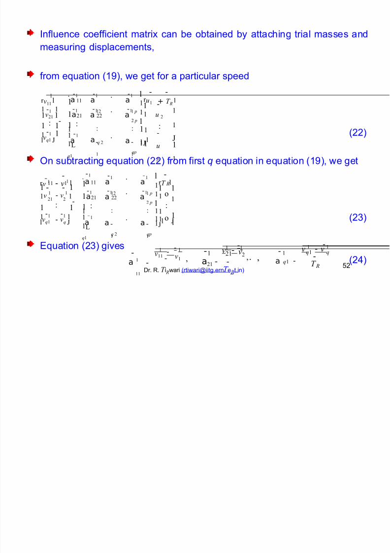
nfluence coefficient matri! can be obtained by
measuring displacements,
attaching trial masses and
from euation (12), we get for a particular speed
1! 1! 1!1 1. l
a a
!2
.
.
.
a
! "
!r #!!
l !r %! + T R l! !!
11! 1! 1!! 1! !
!!
!
!
!
!a
!
!!a a!#2! ! % 2
- 2 " !
2! 22
1
!
1
!
!!!
!!
! !1
%
"
! 1! ! 1! (++)!
l#$! a a $ 2 a$"
!l !L
$!
;n subtracting euation (++) from first ! euation in euation (12), we get
.1! 1! 1!
11 la a
!2
.
.
.
a
! "
r # ! - # ! l !r T l! !!!! ! R
1! 1! 1!! 1 1 ! ! !
!a
!
!!!#! - # !
! a a o
!
!
2! 2 - 2 " ! 2! 22
1
!
1
!
! !!! !! 1! 1! ! ! 1! !!
! (+)l#$! - #$ a a
$ 2
a
$"
o!
l !L
$!
#! -1!
1Buation (+) gives ! -
1 ! # ! - # !1 #2 ,
11 #!! 1 #!
$! $! 2! !
$!a2! - 1. 1
aa !
!!
, --, (+/)T
Dr. R. T i Rwari ([email protected] e Rt.in)%+ R
Page 53
8/18/2019 Docslide.us tggg Balancing of Rotors Ppt
http://slidepdf.com/reader/full/docslideus-tggg-balancing-of-rotors-ppt 53/60
imilarly by attaching a trial mass on plane + we get second
column of the influence coefficient matri! in euation (+/),
above analysis should be done at a constant speed.
the
imilarly
different
we can find the influence coefficient"matri! for
speeds.
Dr. R. Tiwari ([email protected] ) %
Page 54
8/18/2019 Docslide.us tggg Balancing of Rotors Ppt
http://slidepdf.com/reader/full/docslideus-tggg-balancing-of-rotors-ppt 54/60
Dr. R. Tiwari ([email protected] ) %/
Page 55
8/18/2019 Docslide.us tggg Balancing of Rotors Ppt
http://slidepdf.com/reader/full/docslideus-tggg-balancing-of-rotors-ppt 55/60
Dr. R. Tiwari ([email protected] ) %%
Page 56
8/18/2019 Docslide.us tggg Balancing of Rotors Ppt
http://slidepdf.com/reader/full/docslideus-tggg-balancing-of-rotors-ppt 56/60
Dr. R. Tiwari ([email protected] ) %
Page 57
8/18/2019 Docslide.us tggg Balancing of Rotors Ppt
http://slidepdf.com/reader/full/docslideus-tggg-balancing-of-rotors-ppt 57/60
References
$1& . Oellenburger 12*+ Transa"t#ons o$ t%e Amer#"an &o"#ety o$ 'e"%an#"al
En(#neers, Sournal of Bngineering for ndustry 6*, %/"%3.
fle!ible rotor be balanced in ' or '4+ planes
hould a
$+& S. Drechsler 123 )nst#t*t#on o$ 'e"%an#"al En(#neers Con$eren"e on
+#brat#ons #n Rotat#n( 'a"%#nery , 5ambridge, 6O, %"*3. rocessing
surplus information in computer aided balancing of large fle!ible rotors.
$& . Jnil8a 12 ,o*rnal o$ +#brat#on 67, 1%*"1*+. 7odal balancing of
fle!ible rotors without test runs- an e!perimental investigation.
$/& S.7. Orod8iews8i, S. Ding and '. Uhang 122/ ,o*rnal o$ +#brat#on %36,
%"2. dentification of unbalance change using a non"linear
mathematical model for rotor bearing systems.
$%& 7.. Darlow 122, &r#n(er - +erla(. 0alancing of >igh"peedDr. R. Tiwari ([email protected] )
7achinery,%*
Page 58
8/18/2019 Docslide.us tggg Balancing of Rotors Ppt
http://slidepdf.com/reader/full/docslideus-tggg-balancing-of-rotors-ppt 58/60
$& . Bdwards, 9.. =ees and 7.. #riswell +333 ,o*rnal o$ &o*n/ an/
+#brat#on, ')'(%), 2"22+. B!perimental dentification of B!citation and
upport arameters of a #le!ible Rotor"0earings"#oundation ystem from
a ingle Run"Down.
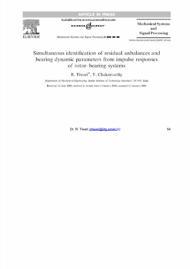
$*& R- Ti8ari, +33%, 'e"%an#"al &ystem an/ &#(nal ro"ess#n( , 5onditioning
of Regression 7atrices for imultaneous Bstimation of the Residual
6nbalance and 0earing Dynamic arameters (in press).
$& %1*+ - 122 pecification for 0alancing 0ench,
$2& 1+*/ - 122+N; 12+% - F Locabulary.
1223 7echanical vibration F 0alancing
$13& 1+*% - 122+N; +*1balancing euipment.
- 12*/ Description and evaluation of field
$11& 1+** - 122+N; +2% - 12% 0alancing machine " Description
and evaluation.Dr. R. Tiwari ([email protected] ) %
Page 59
8/18/2019 Docslide.us tggg Balancing of Rotors Ppt
http://slidepdf.com/reader/full/docslideus-tggg-balancing-of-rotors-ppt 59/60
$1+& 1+* - 1222 N; *12 - 122/ 7echanical Libration " ymbolsfor 0alancing 7achines and 9ssociated nstrumentation.
$1& 1+3 - 122+N; %/3 - 123 7echanical balancing of fle!iblerotors.
$1/& 1/+3 - 122%N; +1 - 122 7echanical vibration " 0alancing" haft and fitment 8ey convention.
$1%& 1/*/ - 1222 N; */*% - 12/ 0alancing 7achines "Bnclosures and ;ther afety 7easures.
$1& 1/21 - +331 7echanical Libration " 7ethodsthe 7echanical 0alancing of #le!ible Rotors
and 5riteria for
Dr. R. Tiwari ([email protected] ) %2
Page 60
8/18/2019 Docslide.us tggg Balancing of Rotors Ppt
http://slidepdf.com/reader/full/docslideus-tggg-balancing-of-rotors-ppt 60/60
Than8 you
Dr. R. Tiwari ([email protected] ) 3