3.1.1. First and second back pass S1 ETG10/20................................................... 7 3.1.2. First two hoppers of bag house S1 ETG30/35............................................ 8 3.1.3. Last two hoppers of bag house S1 ETG80.................................................. 8
3.2. Pipelines ....................................................................................................................... 9 3.2.1. Back pass ....................................................................................................... 9 3.2.2. Bag filter ........................................................................................................ 9
4. AUTOMATION AND INSTRUMENTATION ......................................... 13 4.1. Ash conveying to the fly ash silo from the conveyors S1 ETG10/20/80 AF501…50213 4.2. Ash conveying to the fly ash silo from the conveyors S1 ETG30/35 AF501............ 15 4.3. Wet discharge from silo ............................................................................................. 20
4.3.1. Fly ash outloading sequence ........................................................................ 20 4.4. Dry discharge from the silo........................................................................................ 23
5.2.1. Starting up the conveyors ............................................................................ 24 5.2.2. Starting up wet fly ash unloading from the silo........................................... 26 5.2.3. Starting up dry fly ash wet unloading from the silo .................................... 26
5.3. Normal operation ....................................................................................................... 27 5.4. Shut down .................................................................................................................. 27
5.4.1. Shut down of a pneumatic conveyor............................................................ 27 5.4.2. Shut down of the wet fly ash unloading....................................................... 27 5.4.3. Shut down of the dry fly ash unloading ....................................................... 28
5.5. Troubleshoot for pneumatic conveyors (S1 ETG___-series) ....................................... 28
1. GENERAL A part of the fly ash, that passes through the separator, falls out of the flue gas as it turns through the boiler. To remove this ash there is hoppers located under the back passes and bag house. Hop-pers are made of insulated carbon steel plate and steeply sloped to allow the flow of fly ash. The fly ash conveying system of ESB West Offaly Power comprises the ash removal system, which serves the plant and is intended to collect fly ash from the five different places. These five places are located to be hoppers of economizers (called also back pass one), hoppers of air-preheaters (called also back pass two) and the three fields of bag house pneumatic convey-ors/transmitters. Rest of a fly ash is removed in the end of the flue gas duct at the bag house. Bag house’ pneu-matic conveyors are in order first two as parallel and last two in series, equalling altogether three sender pairs. Ash itself is discharged from the mentioned hoppers to a system of pneumatic conveyor. The conveyors transport the ash to the fly ash silo before removal from the power plant. The fly ash silo is furnished with two separate discharge/unloading systems: − wet discharging system S1 ETK10 − dry discharging system S1 ETK20. Fly ash is discharged from the silo through the rotary feeder, either to the wet or dry discharge. Rotary feeder rotates with constant speed and works with nominal filling grade. Bottom cones of the silo are equipped with fluidizing piping, which facilitates the ash discharge. From the rotary feeder the ash falls into the humidifier or in the other line straight into the lorry.
Document Code: 5 (29)
Issuing date:
Status: rev 0
2. DESIGN DATA
2.1. General The fly ash pneumatic conveying system is designed to convey fly ash from boiler back-pass ash hoppers and discharge points of fly ash at flue gas cleaning device to fly ash storage silo.
2.2. Ash analysis The primary fuel of the Lough Ree Power and West Offaly Power peat fired plants is milled peat. Milled peat has the following typical characteristics:
2.3. Wet discharge main equipment from the fly ash silo
2.3.1. Rotary feeder S1 ETK10 AF501 Rotary feeder transfer the material from ash silo to the fly ash humidifier. Before rotary feeder can operate must the manually operated slide gate, which is located above the rotary feeder, be open. Rotary feeder is equipped with rotation sensor which gives one signal from every round of the rotary feeder. The volume of the rotary feeder is 150 m3 /h. Rotary feeder is equipped with local control switch. Local control switch returned Forward-0-Back typed switch. Backward drive for the rotary feeder is limited to 5 seconds. The new try to backward is allowed when feeder is been driven first to forward.
2.3.2. Fly ash humidifier FAH 1100 S1 ETK10 AF301 Fly ash humidifier FAH 1100 humidifies incoming material from rotary feeder and transfer it to the rail cars ash container. Fly ash humidifier is equipped with high pressure cleaning device which cleans the humidifier screw automatically if the cleaning sequence is chosen by the operator. Fly ash humidifier is equipped with lubrication unit which lubricate humidifier and rotary feeder automatically and independently.
2.4. Dry discharge main equipment from the fly ash silo
2.4.1. Rotary feeder ALF 50/50 S1 ETK20 AF501 Rotary feeder transfer the material from ashsilo to the dry ash outloading equip-ment. Before rotary feeder can operate must the manually operated slide gate which is located above the rotary feeder be open. Rotary feeder is equipped with rotation sensor which gives one signal from every round of the rotary feeder. The volume of the rotary feeder is 150 m3 /h. Rotary feeder is equipped with local control switch. Local control switch returned Forward-0-Back typed switch. Backward drive for the rotary feeder is limited to 5 seconds. The new try to backward is allowed when feeder is been driven first to forward.
2.4.2. Dry ash outloading equipment S1 ETK20 AF901 Dry ash outloading equipment transfers dry ash from ash silo to dry ash con-tainer rail. The volume of dry ash outloading is 120 m3 /h Dry ash outloaded is equipped with local control switches which start and stops the outloading se-quence.
Document Code: 7 (29)
Issuing date:
Status: rev 0
3. EQUIPMENT DATA
3.1. Pneumatic conveyors
3.1.1. First and second back pass S1 ETG10/20 Manufacturer Pneuplan Oy Number of senders 2 S1 ETG10 Number of senders 2 S1 ETG20 Capacity 0,359 kg/s S1 ETG10/20 Temperature max. 300 °C S1 ETG10 Temperature max. 170 °C S1 ETG20 First back pass S1 ETG10 Second back pass S1 ETG20 − Type Pneumatic conveyor unit 40T/200 − Volume 40 litre − Structural pressure 10 bar − Material cast iron − Fill-up valve NS 200 dome valve −
stainless steel dome, sealing material viton and first back pass water-cooled
− Rotameter with ind.limit switch for cooling water − Air inlet valve group 1 pc for 2 conveyors − Hopper upper side of hopper 327x327 slide gate service
valve. Equipped with a level probe. − Instrument box, with necessary solenoid valves and pressure switches for lo-
cal control, 1 pcs for two conveyors. − Control through DCS systems
Document Code: 8 (29)
Issuing date:
Status: rev 0
3.1.2. First two hoppers of bag house S1 ETG30/35 Manufacturer Pneuplan Oy Number of senders 1 S1 ETG30 Number of senders 1 S1 ETG35 Capacity 8,1 kg/s / sender S1 ETG30/35 Temperature max. 170 °C S1 ETG30/35 First bag house hopper at the left side S1 ETG30 First bag house hopper at the right side S1 ETG35 − Type Pneumatic conveyor unit 1800/300 − Volume 1800 litre − Structural pressure 10 bar − Material structural steel − Fill-up valve NS 300 dome valve stainless steel dome, sealing material butyl − Air inlet valve group 1 set for 1 conveyor − Hopper upper side of hopper 327x327 slide gate service
valve. Equipped with a level probe. − Instrument box, with necessary solenoid valves and pressure switches for lo-
cal control, 1 pcs per conveyor − Control through DCS systems − Hopper volume 2 m3 − Hopper material structural steel − Ventilation pipe DN 100, ~ 12 m
3.1.3. Last two hoppers of bag house S1 ETG80 Manufacturer Pneuplan Oy Number of senders 2 S1 ETG80 Capacity 0,869 kg/s 0,435 kg/s per hopper Temperature max. 170 °C Bag house’ last two hoppers constructed in series S1 ETG80 − Hopper volume 200 litre − Hopper material structural steel − Ventilation pipe DN 100, ~ 12 m
Document Code: 9 (29)
Issuing date:
Status: rev 0
− Type Pneumatic conveyor unit 200T/200 − Volume 200 litre − Structural pressure 10 bar − Material structural steel − Fill-up valve NS 200 dome valve stainless steel dome, sealing material butyl − Air inlet valve group 1 set for 1 conveyor − Hopper upper side of hopper 327x327 slide gate service valve − Equipped with a level probe − Instrument box, with necessary solenoid valves and pressure switches for lo-
cal control, 1 pcs per conveyor. − Control through DCS systems
3.2. Pipelines
3.2.1. Back pass − Pipeline size DN 100 pipe with special flanges − Number of lines 2 − Curves special cast basalt curves, 8 pcs / pipeline − Auxiliary All necessary pipe clamps, screws, nuts and o-rings − End box 2x DN 150 2x DN 100 shared with bag filter conveying lines
3.2.2. Bag filter − Pipeline size DN 200 pipe with special flanges − Number of lines 2 − Piping ~125 m 8x 90º pipe bends − Curves Special cast basalt curves, 8 pcs / pipeline ) − Auxiliary All necessary pipe clamps, screws, nuts and o-rings
Document Code: 10 (29)
Issuing date:
Status: rev 0
3.3. Fly ash silo equipments S1 EH10 BB101
3.3.1. Air filter S1 ETH10 AT201 Manufacturer Pneuplan Oy Location top of the fly ash silo, with counter flange Number of filters 1 pc Surface area 30 m� Fucntion counter pressure cleaning Blower 2,2 kW (ABB motor, 400 V)
R1/2 “ ball valve for instrument air
3.3.2. Relief valve Manufacturer Pneuplan Oy Over pressure valve size DN 200 S1 ETH10 AA301 Number of valves 1 pc Vacuum valve size DN 100 S1 ETH10 AA302 Number of valves 1 pc
3.3.3. Silo fluidization Number of fluidization rings 2 pcs S1 ETP40/45 Fluidization ring with 4 pcs of one way nozzles Other equipment R1” manual ball valve 1 pc R1” pressure regulator 1 pc R1” ball valve with actuator 1 pc
3.4. Fly ash silo discharge equipment
3.4.1. Manually operated slide gates S1 ETK10/20 AA001 Manufacturer Raumaster Oy Number of gates 2 Size 500 x 500 Material − frame carbon steel − slide stainless − plate steel
Document Code: 11 (29)
Issuing date:
Status: rev 0
3.4.2. Rotary feeders S1 ETK10/20 AF501 Manufacturer Raumaster Oy Number of units 2 Type ALF 50/50 Capacity 150 m3/h Rotation speed 20 rpm Motor 5,5 kW (Siemens 400 V; 50 Hz; 1500 rpm) Filling grade 85 % Rotors volume 146 l Gear Kumera TFM-3140H1-71-LA-38F265 Bracket for zero switch Z = 4 and volume indicator Z = 1 Zero switch Telemecanique XSA-V11801 Volume indicator Telemecanique XS1-M30MA230B Shaft sealing Packing housing (3 seals and a grease ring) Lubrication Safematic central lubrication system Materials − inner lining of cells Stainless steel − other parts Carbon steel
3.4.3. Fly ash humidifier S1 ETK10 AF301 Manufacturer Raumaster Oy Type FAH 1100 Capacity 150 m3/h Rotation speed 75 rpm Motor 45 kW (Siemens 400 V; 50 Hz; 1500 rpm) Gear Kumera RFM-3180H1-20-LA-60F400 Bracket for zero speed switch Z = 9 Zero switch Telemecanique XSA-V11801 Mixing screws 2 pieces, ¢ 630 mm − paddles PL15 mm stainless steel with ceramic wearing
parts Shaft sealing Packing housing (3 seals and a grease ring) Lubrication Safematic central lubrication system Material (through) PL 6 mm stainless steel
The humidifier is equipped with humidification piping, which is dealt to separate humidification areas by magnet valves. It contains closing valve (ball valve), filter for coming water and water spray nozzles. Outlet chute is equipped with flexible (fabric) lower part L= ~1,5 m.
Document Code: 12 (29)
Issuing date:
Status: rev 0
3.4.4. Cleaning system for fly ash humidifier S1 GHH11 Manufacturer Raumaster Oy Type FAH 1100 Rotating washing nozzles 6 pcs Capacity 21 L/min with high pressure pump Motor 5,5 kW Water consumption ~200-250 L/wash
3.4.5. Automatic lubrication unit S1 ETV10 AP001 Manufacturer Safematic By automatic lubrication unit is lubricated Fly
Ash Humidifier FAH 1100 and Rotary Feeder ALF 50/50 in the same line Greasing points 10 pcs - shaft sealings 4 pcs in FAH 1100 and
2 pcs in ALF 50/50 - bearings 2 pcs in FAH 1100 and 2 pcs in ALF 50/50
Piping Ø6 mm stainless steel The lubrication unit is mounted to the frame of the humidifier
3.4.6. Dry out loading unit S1 ETK20/30 AF901 Manufacturer Raumaster Oy Number of units 2 Capacity 120 m3/h each Material temperature < 200 °C Motor 0,55 kW (Siemens 400 V; 50 Hz; 1500 rpm) Gear SEW-Eurodrive SA57 17rpm / min Outlet chute D = 600 mm, movement 2500 mm, glass fibre and steel cones Infeed chute L = 2 m Dust removal system DN 150, pneumatic actuator Needed air quantity for dust removal 2000 m³/h, 2000 Pa (by customer). Dust extraction pipe from dry loader is led to the upper part of the silo. The dry outloading unit is equipped with housing, control unit, terminal box, and regulating unit.
Document Code: 13 (29)
Issuing date:
Status: rev 0
4. AUTOMATION AND INSTRUMENTATION In this section automation is explained only basic level and more detailed descriptions can be found in Automation Descriptions
4.1. Ash conveying to the fly ash silo from the conveyors S1 ETG10/20/80 AF501…502 S1 ETG10 AF501…502 equals conveyors of the first back pass S1 ETG20 AF501…502 equals conveyors of the second back pass S1 ETG80 AF501…502 equals conveyors of the second field of the bag house
Document Code: 14 (29)
Issuing date:
Status: rev 0
Document Code: 15 (29)
Issuing date:
Status: rev 0
4.2. Ash conveying to the fly ash silo from the conveyors S1 ETG30/35 AF501 L1 ETG30/35 AF501 equals conveyors of the first field of the bag house
Document Code: 16 (29)
Issuing date:
Status: rev 0
Document Code: 17 (29)
Issuing date:
Status: rev 0
Document Code: 18 (29)
Issuing date:
Status: rev 0
Document Code: 19 (29)
Issuing date:
Status: rev 0
Document Code: 20 (29)
Issuing date:
Status: rev 0
4.3. Wet discharge from silo
4.3.1. Fly ash outloading sequence 1. OUTLOADING SEQUENCE READY − Automatic mode selected. − No alarms. 2. START ORDER FROM OPERATOR − Start switch at control panel. 3. START THE HUMIDIFIER SCREW S1ETK10AF301-M01 4. DELAY 5 SECONDS. 5. OPEN HUMIDIFIER WATER VALVE 1 S1GHH10AA901 AND START THE FLUIDIZATION. 6. START ROTARY FEEDER S1ETK10AF501-M01 7. DELAY 5 SECONDS 8. OPEN HUMIDIFIER WATER VALVE 2 S1GHH10AA902 9. DELAY 5 SECONDS 10. OPEN HUMIDIFIER WATER VALVE 3 S1GHH10AA903 11. OUTLOADING SEQUENCE RUNNING. 12. STOP ORDER FROM OPERATOR. − Stop switch at control panel. 13. STOP THE ROTARY FEEDER S1ETK10AF501-M01 AND STOP THE FLUIDIZATION. 14. DELAY 10 SECONDS. 15. CLOSE THE HUMIDIFIER WATER VALVE 1 S1GHH10AA901 16. DELAY 10 SECONDS 17. CLOSE THE HUMIDIFIER WATER VALVE 2 S1GHH10AA902 18. DELAY 10 SECONDS.
Document Code: 21 (29)
Issuing date:
Status: rev 0
19. CLOSE THE HUMIDIFIER WATER VALVE 3 S1GHH10AA903 S1ETK__-MDC6003 FUNCTIONAL DESCRIPTION FOR FLY ASH DISCHARGE EQUIPMENT 7(10) FLY ASH HANDLING SYSTEM 20. IF THE WASHING SEQUENCE IS SELECTED GO TO STEP 21. IF THE WASHING SEQUENCE IS NOT SELECTED JUMP TO STEP 47. − Washing sequence is selected switch at control panel. 21. OPEN THE WASHING VALVE 1 S1GHH11AA901 22. START HIGH PRESSURE PUMP S1GHH11AP101-M01 23. DELAY 100 SECONDS. 24. OPEN THE WASHING VALVE 2 S1GHH11AA902 25. DELAY 15 SECONDS 26. CLOSE THE WASHING VALVE 1 S1GHH11AA901 27. DELAY 100 SECONDS. 28. OPEN THE WASHING VALVE 3 S1GHH11AA903 29. DELAY 15 SECONDS. 30. CLOSE THE WASHING VALVE 2 S1GHH11AA902 31. DELAY 100 SECONDS. 32. OPEN THE WASHING VALVE 4 S1GHH11AA904 33. DELAY 15 SECONDS 34. CLOSE THE WASHING VALVE 3 S1GHH11AA903 35. DELAY 100 SECONDS 36. OPEN WASHING VALVE 5 S1GHH11AA905 37. DELAY 15 SECONDS. 38. CLOSE THE WASHING VALVE 4 S1GHH11AA904 39. DELAY 100 SECONDS. 40. OPEN WASHING VALVE 6 S1GHH11AA906
Document Code: 22 (29)
Issuing date:
Status: rev 0
41. DELAY 15 SECONDS. 42. CLOSE THE WASHING VALVE 5 S1GHH11AA905 43. DELAY 100 SECONDS. 44. STOP THE HIGH PRESSURE PUMP S1GHH11AP101-M01 45. DELAY 5 SECONDS. 46. CLOSE THE WASHING VALVE 6 S1GHH11AA906 47. DELAY 30 SECONDS. 48. STOP THE HUMIDIFIER SCREW S1ETK10AF301-M01 49. OUTLOADING SEQUENCY STOPPED.
Document Code: 23 (29)
Issuing date:
Status: rev 0
4.4. Dry discharge from the silo
4.4.1. Dry ash outloading sequence 1. Manually open slide gate S1ETK20AA001 2. Drive ouloading bellows to down position. Bellows is driven manually
from local control switch. When the control switch is not pushed then the bellows is stopped. Bellows movement is automatically stopped when the limit switch S1ETK20CG102 is activated.
3. When the bellows is dropped from upper limit switch S1ETK20CG101.
- The outloading control valve S1ETK20AA902 open. - The outgoing air valve S1ETK20AA101 open. - Dust filter fan motor S1ETH10AN401-M01 is started.
4. Rotary feeder S1ETK20AF501 can be started from local control switch
start outloading. Rotary feeder can be stopped from local control switch stop outloading.
5. When the outloaded material level reaches the high level and level switch
S1ETK20CL101 is activated then the rotary feeder S1ETK20AF501 is automatically stopped. The rotary feeder can be re-started from local con-trol switch when the level in container is dropped and the level switch S1ETK20CL101 is deactivated.
6. When the material outloading is stopped the bellows is driven up position
manually from local control switch. When the control switch is not pushed then the bellows is stopped. Bellows movement is automatically stopped when the limit switch S1ETK20CG101 IS activated.
7. When the bellows reach the upper limit switch S1ETK20CG101.
- The outloading control valve S1ETK20AA902 closed. - Delay 30 second - Dust filter fan motor S1ETH10AN401-M01 stop. - The outgoing air valve S1ETK20AA101 close.
8. Dry ash outloading sequence ready.
Document Code: 24 (29)
Issuing date:
Status: rev 0
5. OPERATION See also the manufacturer documentation of the Pneuplan Oy and Raumaster Oy. Manufacturer operation, safety and maintenance instructions has to be noted and followed.
5.1. Start-up pre-check Check, that: − any device of the system is not damaged − all devices maintenance and mandoors has been closed − all controlled devices are electrically connected − all manually controlled equipments are in correct position: opened / closed − all devices are ready for safe operation (f.e. over pressure valves are checked =OK, etc.)
5.2. Start-up
5.2.1. Starting up the conveyors Ensure, that first and second back pass: − fly ash closing valves, S1 ETG10/20 AA001…002, are opened − pressure air hand valves, S1 ETP10/20 AA002, are opened − instrument air hand valves, S1 QFD10/20 AA002, are opened − closed cooling water hand valves, S1 PGE11/12 AA001, are opened. − closed cooling water flows, S1 PGF11/12 CF001/101, are normal. − fly ash backwards discharge valves, S1 ETG10/20 AA810 and
S1 ETG10/20 AA020, are closed. Ensure, that bag house first and second field: − fly ash closing gates from bag house, S1 ETG30/35/80 AA_____, are opened − 0conveyors hand valves, S1 ETG30/35 AA001, S1 ETG80 AA001…002, S1
ETG30/35 AA810 and S1 QFD30/35/80 AA003, are closed − pressure air hand valves, S1 ETP30/31/35/36/80 AA002, are opened − instrument air hand valves, S1 QFD30/35/80 AA002, are opened After that go through locally each conveyor and: a) Open the service valve b) Open the air intake valve c) Open instrument air valve d) Make sure the supply pressure is higher than 5 bars e) Turn the conveying cycle to position “1”. f) Turn the fill-up switch to position “1”.
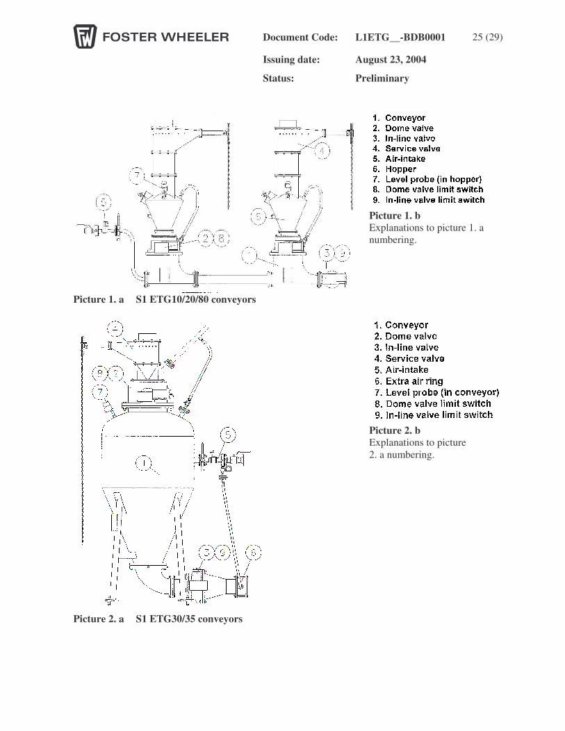
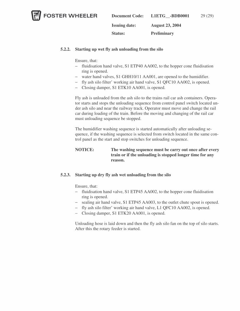
Both conveyor systems, mentioned at pictures 1. a and 2. a on the following page, has local switch board, where the switch has to be drawn to position “1”.
Document Code: L1ETG__-BDB0001 25 (29)
Issuing date: August 23, 2004
Status: Preliminary
Picture 1. a S1 ETG10/20/80 conveyors
Picture 2. a S1 ETG30/35 conveyors
Picture 1. b Explanations to picture 1. a numbering.
Picture 2. b Explanations to picture 2. a numbering.
Document Code: L1ETG__-BDB0001 29 (29)
Issuing date: August 23, 2004
Status: Preliminary
5.2.2. Starting up wet fly ash unloading from the silo Ensure, that: − fluidisation hand valve, S1 ETP40 AA002, to the hopper cone fluidisation
ring is opened. − water hand valves, S1 GHH10/11 AA001, are opened to the humidifier. − fly ash silo filter’ working air hand valve, S1 QFC10 AA002, is opened. − Closing damper, S1 ETK10 AA001, is opened. Fly ash is unloaded from the ash silo to the trains rail car ash containers. Opera-tor starts and stops the unloading sequence from control panel switch located un-der ash silo and near the railway track. Operator must move and change the rail car during loading of the train. Before the moving and changing of the rail car must unloading sequence be stopped. The humidifier washing sequence is started automatically after unloading se-quence, if the washing sequence is selected from switch located in the same con-trol panel as the start and stop switches for unloading sequence. NOTICE: The washing sequence must be carry out once after every
train or if the unloading is stopped longer time for any reason.
5.2.3. Starting up dry fly ash wet unloading from the silo Ensure, that: − fluidisation hand valve, S1 ETP45 AA002, to the hopper cone fluidisation
ring is opened. − sealing air hand valve, S1 ETP45 AA003, to the outlet chute spout is opened. − fly ash silo filter’ working air hand valve, L1 QFC10 AA002, is opened. − Closing damper, S1 ETK20 AA001, is opened. Unloading hose is laid down and then the fly ash silo fan on the top of silo starts. After this the rotary feeder is started.
Document Code: L1ETG__-BDB0001 29 (29)
Issuing date: August 23, 2004
Status: Preliminary
5.3. Normal operation All systems needs normal monitoring from the DCS system, but also local controlling in daily period to see, that there are no unusual noises, leakages, breakdowns or other un-usual observations to be noticed. DCS systems shows from the continuous measurement function of the pneumatic con-veyors as well the need for the fly ash silo unloading. With the help of DCS system alarms, operator is able noticed f.e. malfunction at the pneumatic conveying. If there is a blockage at the system, operator is needed to re-solve/discharge blockage locally. All pneumatic conveyors should work properly and send sly ash automatically to the fly ash silo from the level indicator signal (level indicators of senders are needed to be tuned in the commissioning period to the correct fly ash conductivity) or after certain minimum cycle. Fly ash silo unloading is needed to discharge locally – either with dry or wet unloading system (for which the lorry is ordered). Fly ash silo filter (S1 ETH10 AT201) functions auto-matically from the silo unloading signal or anyway after a timer.
5.4. Shut down
5.4.1. Shut down of a pneumatic conveyor Each pneumatic conveyor can be taken away from operation or shut down from DCS or/and locally. From the DCS sender will be switched OFF and locally switch will be turned to position “0”.
5.4.2. Shut down of the wet fly ash unloading If emergency stop is pushed or some other interlock stops the sequence operation is stopped immediately and when the alarms is been resetting the sequence starts from step 1. Every equipment has its own 0 / start-selector switch. All the delay times in description are preliminary and the right times must be checked during commissioning.
5.4.3. Shut down of the dry fly ash unloading When the level switch gives indication "truck full", the rotary feeder stops. The unloading hose is lifted up and then the fly ash silo fan stops. Every equipment has its own 0 / start-selector switch.