Master Classes Document: ETG.1500 D (R) 1.0.2 Nomenclature: ETG-Number ETG.1500 Type D (Directive) State R (Release) Version 1.0.2 Created by: ETG Contact: [email protected]Filename: ETG1500_D_MasterClasses.docx Date: 19.05.16
Transcript
Master Classes
Document: ETG.1500 D (R) 1.0.2
Nomenclature: ETG-Number ETG.1500 Type D (Directive) State R (Release) Version 1.0.2
Created by: ETG Contact: [email protected] Filename: ETG1500_D_MasterClasses.docx Date: 19.05.16
EtherCAT® is a registered trademark and patented technology, licensed by Beckhoff Automation GmbH, Germany. Other designations used in this publication may be trademarks whose use by third parties for their own purposes could violate the rights of the owners.
Disclaimer
The documentation has been prepared with care. The technology described is, however, constantly under development. For that reason the documentation is not in every case checked for consistency with performance data, standards or other characteristics. In the event that it contains technical or editorial errors, we retain the right to make alterations at any time and without warning. No claims for the modification of products that have already been supplied may be made on the basis of the data, diagrams and descriptions in this documentation.
The reproduction, distribution and utilization of this document as well as the communication of its contents to others without express authorization is prohibited. Offenders will be held liable for the payment of damages. All rights reserved in the event of the grant of a patent, utility model or design.
ETG.1500, EtherCAT Master Classes III
DOCUMENT HISTORY
Version Comment
1.0.0 First outline
1.0.1 Removed ETG.1400 reference and update ETG.8000 Name
1.0.2 Replaced ETG.1400 by ETG.8000 throughout the document
Figure 1: EtherCAT Master and Configuration Tool Structure ................................................................ 5 Figure 2: The cable redundancy principle ............................................................................................ 19
ETG.1500, EtherCAT Master Classes VIII
ABBREVIATIONS
µC Microcontroller C Conditional CMD Command CoE CANopen over EtherCAT DC Distributed Clock DPRAM Dual-Ported RAM ENI EtherCAT Network Information (EtherCAT XML Master Configuration) EoE Ethernet over EtherCAT ESC EtherCAT Slave Controller ESI EtherCAT Slave Information (EtherCAT Devices Description) ESM EtherCAT State Machine ETG EtherCAT Technology Group FMMU Fieldbus Memory Management Unit FoE File Access over EtherCAT FPMR Configured Address Physical Read Multiple Write FPRD Configured Address Physical Read FPRW Configured Address Physical ReadWrite FPWR Configured Address Physical Write I/O Input/Output IDN Identification Number (Servo Profile Identifier) IEC International Electrotechnical Commission INT Integer IRQ Interrupt Request LRD Logical Read LRW Logical ReadWrite LSB Least Significant Bit LWR Logical Write M Mandatory MAC Media Access Controller MI (PHY) Management Interface MII Media Independent Interface MSB Most Significant Bit NIC Network Interface Card NOP No Operation ns nanoseconds (10-9 seconds) O Optional OD Object Dictionary OS Oversampling PDO Process Data Object DLPDU Data-Link Layer Process Data Unit PreOp Pre-Operational RD Read SDO Service Data Object SII Slave Information Interface (EEPROM content) SM SyncManager SoE Servo Profile over EtherCAT SOF Start of Frame SPI Serial Peripheral Interface SU Sync Unit WD Watchdog WKC Working Counter WR Write XML eXtensible Markup Language
Scope
ETG.1500, EtherCAT Master Classes 1
GLOSSARY
configurator configuration tool or configuration logic
Scope
ETG.1500, EtherCAT Master Classes 2
1 Scope
End users and/ or System integrators expect a defined minimum functionality and interoperability when selecting an EtherCAT Master device. But not every master has to support all features of the EtherCAT Technology.
This specification defines Master Classes with a well-defined set of Master functionalities. In order to keep things simple only 2 Master Classes are defined:
Class A: Standard EtherCAT Master Device
Class B: Minimum EtherCAT Master Device
The principle idea is that each implementation should aim to meet Class A requirements. Only if resources prohibit, e.g. on embedded systems, at least Class B shall be met.
Additional Functionality, which can be considered to be optional, is described by Feature Packs. The Feature Pack describes all mandatory master functionality for a specific feature, e.g. Redundancy.
References
ETG.1500, EtherCAT Master Classes 3
2 References
The following referenced documents are indispensable for the application of this document. For dated references, only the edition cited applies. For undated references, the latest edition of the referenced document (including any amendments) applies.
ETG Standards
[1] ETG.1000.2: Physical Layer service definition and protocol specification
[2] ETG.1000.3: Data Link Layer service definition
[3] ETG.1000.4: Data Link Layer protocol specification
[4] ETG.1000.5: Application Layer service definition
[7] ETG.1020: EtherCAT Guidelines and Protocol Enhancements
[8] ETG.2000: EtherCAT Slave Information
[9] ETG.2100: EtherCAT Network Information
[10] ETG.5001: EtherCAT Modular Device Profiles
[11] ETG.6010: EtherCAT Implementation Guideline for CiA402 Drive Profile
[12] ETG.8000: EtherCAT Knowledge Base
Other References
[13] IEC 61158-x-12 (all parts for type 12): Industrial communication networks – Fieldbus specifications
[14] IEC 61784-2: Industrial communication networks – Profiles – Part 2: Additional fieldbus profiles for real-time networks based on ISO/IEC 8802-3
[15] IEC 61800-7: Adjustable speed electrical power drives systems – Part 7: Generic interface and use of profiles for power drive systems
Terms, Definitions and Word Usage
ETG.1500, EtherCAT Master Classes 4
3 Terms, Definitions and Word Usage
3.1 Terms and Definitions
The terms and definitions of ETG.1000 series shall be fully valid, unless otherwise stated.
3.2 Word usage: shall, should, may, can
The word shall is used to indicate mandatory requirements to be followed in order to conform to the directive and from which no deviation is permitted (shall equals is required to).
The word should is used to indicate that among several possibilities one is recommended as particularly suitable, without mentioning or excluding others; or that a certain course of action is preferred but not necessarily required; or that (in the negative form) a certain course of action is deprecated but not prohibited (should equals is recommended that). The support of this possibility increases performance of the system or broadens the support of devices or functionalities which are used in a relatively small number of implementations.
The word may is used to indicate a course of action permissible within the limits of the standard (may equals is permitted to). The support of this possibility is used for optimization and mainly implemented for concrete use cases only.
The word can is used for statements of possibility and capability, whether material, physical, or causal (can equals is able to).
Master Classes
ETG.1500, EtherCAT Master Classes 5
4 Master Classes
4.1 Introduction
The main tasks of an EtherCAT master are the network initialization and the handling of the state machines of all devices, the process data communication and providing acyclic access for parameter data exchange between master application and slave.
However, the master itself does not collect the information for the list of initialization and cyclic commands. This is done by a network configuration logic. In many cases this is an EtherCAT network configuration software.
The configuration logic collects the necessary information from the ESI or the SII, ESC registers and object dictionary or IDN list and generates the EtherCAT Network Information (ENI). This is provided to the EtherCAT master.
Mailbox
Services
acyclic
commands
cyclic
req. resp.
commands
Eth
erC
AT
Ma
ste
r
Ne
wo
rk
Co
nfig
ura
tio
n L
og
ic
EtherCAT Slave Information
(ESI)
EtherCAT Network Information
EtherCAT Network
Application
Process Data
ImageS
lave
OD/
IDN LIst
ESC
RegistersSII
Device Profile
Figure 1: EtherCAT Master and Configuration Tool Structure
Configuration Functionality: Either Configuration Tool or Configuration functionality in Master In the following this is referred to as configuration tool. This represents both versions.
Master application may be a PLC or Motion Control function, or online diagnosis application.
4.2 Master Class A
A Master Class A device shall support all functions that are described by the ETG specification ETG.1000 series as well as many functions of the ETG.1020. Additional functions are listed in the requirement specification, see Table 1.
Master devices should support the Master Class A requirements.
4.3 Master Class B
The Master Class B has reduced functionality compared to Class A. The main functions that are needed to run most of the EtherCAT devices (e.g. support of CoE, cyclic process data exchange) are required for this master.
Master Classes
ETG.1500, EtherCAT Master Classes 6
Only master devices those are not able to fulfill Master Class A requirements shall fulfill Master Class B requirements.
4.4 Feature Packs
Feature Packs (FP) defines sets of optional functionality. If a FP is supported than all functions of the listed requirements shall be fulfilled.
4.5 Validity of Master Classes and Feature Packs
The definition of Master Classes and Feature Packs is an ongoing process due to enhancements of the technology and additional features needed to satisfy upcoming requirements from customers and applications.
The Master Classes are meant to take those enhancements into account to the end-user’s benefit. Therefore, the range of functionalities of the basic feature set and each individual Feature Pack is identified by a version number.
The Master vendor must not classify his Master Classes implementation (basic feature set as well as each Feature Packs) without the corresponding version numbers.
Master Classes Requirement Specification
ETG.1500, EtherCAT Master Classes 7
5 Master Classes Requirement Specification
5.1 Version history Master Classes specification
Version history Master Class A
Version Comment
1.0.0 First release
Version history Master Class B
Version Comment
1.0.0 First release
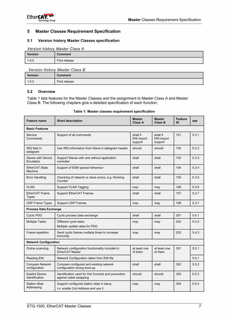
5.2 Overview
Table 1 lists features for the Master Classes and the assignment to Master Class A and Master Class B. The following chapters give a detailed specification of each function.
Table 1: Master classes requirement specification
Feature name Short description Master Class A
Master Class B
Feature ID
see
Basic Features
Service Commands
Support of all commands shall if ENI import support
shall if ENI import support
101 5.3.1
IRQ field in datagram
Use IRQ information from Slave in datagram header should should 102 5.3.2
Slaves with Device Emulation
Support Slaves with and without application controller
shall shall 103 5.3.3
EtherCAT State Machine
Support of ESM special behaviour shall shall 104 5.3.4
Error Handling Checking of network or slave errors, e.g. Working Counter
shall shall 105 5.3.5
VLAN Support VLAN Tagging may may 106 5.3.6
EtherCAT Frame Types
Support EtherCAT Frames shall shall 107 5.3.7
UDP Frame Types Support UDP Frames may may 108 5.3.7
Process Data Exchange
Cyclic PDO Cyclic process data exchange shall shall 201 5.4.1
Multiple Tasks Different cycle tasks
Multiple update rates for PDO
may may 202 5.4.2
Frame repetition Send cyclic frames multiple times to increase immunity
may may 203 5.4.3
Network Configuration
Online scanning Network configuration functionality included in EtherCAT Master
at least one of them
at least one of them
301 5.5.1
Reading ENI Network Configuration taken from ENI file 5.5.1
Compare Network configuration
Compare configured and existing network configuration during boot-up
shall shall 302 5.5.2
Explicit Device Identification
Identification used for Hot Connect and prevention against cable swapping
should should 303 5.5.3
Station Alias Addressing
Support configured station alias in slave,
i.e. enable 2nd Address and use it
may may 304 5.5.4
Master Classes Requirement Specification
ETG.1500, EtherCAT Master Classes 8
Feature name Short description Master Class A
Master Class B
Feature ID
see
Access to EEPROM
Support routines to access EEPROM via ESC register
Read shall
Write may
Read shall Write may
305 5.5.5
Mailbox Support
Support Mailbox Main functionality for mailbox transfer shall shall 401 5.6.1
Mailbox Resilient Layer
Support underlying resilient layer shall shall 402 5.6.2
Multiple Mailbox channels
may may 403 5.6.3
Mailbox polling Polling Mailbox state in slaves
shall shall 404 5.6.4
CAN application layer over EtherCAT (CoE)
SDO Up/Download Normal and expedited transfer shall shall 501 5.7.1
Segmented Transfer
Segmented transfer shall should 502 5.7.2
Complete Access Transfer the entire object (with all sub-indices) at once
shall should
shall if ENI Import supported
503 5.7.3
SDO Info service Services to read object dictionary shall should 504 5.7.4
Emergency Message
Receive Emergency messages shall shall 505 5.7.5
PDO in CoE PDO services transmitted via CoE may may 506 5.7.6
EoE
EoE protocol Services for tunneling Ethernet frames. includes all specified EoE services
shall shall if EoE support
601 5.8.1
Virtual Switch Virtual Switch functionality shall shall if EoE support
602 5.8.2
EoE Endpoint to Operation Systems
Interface to the Operation System on top of the EoE layer
should should if EoE support
603 5.8.3
FoE
FoE Protocol Support FoE Protocol shall shall if FoE support
701 5.9.1
Firmware Up-/Download
Password, FileName should be given by the application
shall should 702 5.9.1
Boot State Support Boot-State for Firmware Up/Download shall shall if FW UP/ Download
703 5.9.2
SoE
SoE Services Support SoE Services shall should if SoE support
801 5.10.1
AoE
AoE Protocol Support AoE Protocol should should 901 5.11.1
VoE
VoE Protocol External Connectivity supported may may 1001 5.12.1
Synchronization with Distributed Clock (DC)
DC support Support of Distributed Clock shall shall if DC support
1101 5.13.1
Master Classes Requirement Specification
ETG.1500, EtherCAT Master Classes 9
Feature name Short description Master Class A
Master Class B
Feature ID
see
Continuous Propagation Delay compensation
Continuous Calculation of the propagation delay should should 1102 5.13.2
Sync window monitoring
Continuous monitoring of the Synchronization difference in the slaves
should should 1103 5.13.3
Slave-to-Slave Communication
via Master Information is given in ENI file or can be part of any other network configuration
Copying of the data can be handled by master stack or master’s application
shall shall 1201 5.14
Master information
Master Object Dictionary
Support of Master Object Dictionary (ETG.5001 MDP sub profile 1100)
should may 1301 5.15.1
5.3 Basic Functions
5.3.1 Service Commands
Description
The EtherCAT datagrams (DLPDU) uses several service commands to address data in the network.
Reference
ETG.1000.3 and ETG.1000.4
Note
Some slaves do not support LRW commands. The configurator has to take care if the flag UseLrdLwr is set in the ESI file / SII.
Implementation Aspect
The network configuration is done by the configuration tool (even a separated configuration tool or integrated in the master functionality). This configuration tool may use several commands to start-up the network and to cyclic update the process image.
If the Master supports internal configuration capability, it may reduce the variety of commands
5.3.2 IRQ Field in datagram
Description
The EtherCAT datagrams (DLPDU) contains an IRQ field. The Master may use the IRQ field to get information from the slaves.
Reference
ETG.1000.3 and ETG.1000.4
Note
It has to be considered, that the IRQ bits are ORed by all slaves and that the bits are set in all datagrams of a frame.
Use Case
Detect a change of the DL Status event, e.g. when a device is connected to or disconnected from the network; especially for hot connect applications
Master Classes Requirement Specification
ETG.1500, EtherCAT Master Classes 10
5.3.3 Slaves with Device Emulation
Description
There are slaves which confirm the AL Management services with (device emulation = true) or without (device emulation = false) any reaction within the local application.
The master should not set the Error Indication Acknowledge bit for slaves with device emulation = true at all, because setting this bit would result in setting the Error Indication bit – although no error occurred.
5.3.4 EtherCAT State Machine (ESM)
Description
The EtherCAT State Machine defines the network behaviour of the master and of the slaves.
Reference
ETG.1000.5 and ETG.1000.6
ETG.1020, SII Specification
Implementation Aspect
The Timeout values for the ESM transitions from the ESI / SII shall be used. If no timeout values are available the default timeouts defined in ETG.1020 shall be used.
If the OpOnly Flag is set in the ESI file / SII the Master shall disable the SyncManager of all outputs if not in state Operational (this can be part of the network configuration Init Commands).
5.3.5 Error Handling
Description
The Error Handling defines a unique behaviour of EtherCAT devices (Masters and Slaves) in cases of communication problems.
Reference
ETG.1020 Error Handling
Implementation Aspect
Evaluation of the PDO Parameter, like PDO Toggle or PDO state, can be done in the application.
Master shall support an interface to the application which provides access to error and diagnosis information (e.g. error register, Diagnosis object).
5.3.6 VLAN
Description
The VLAN Tag can be used for classification of a frame.
Reference
ETG.1000.4 DLPDU structure
Master Classes Requirement Specification
ETG.1500, EtherCAT Master Classes 11
5.3.7 Ethernet Frame Types
Description
The EtherCAT datagrams are transferred inside an Ethernet frames with EtherType = 0x88A4 and with EtherCAT Header Type = 1.
The EtherCAT Frame may also be transferred inside a UDP datagram (EtherType = 0x0800, UDP-Port = 0x88A4).
Reference
ETG.1000.3 and ETG.1000.4
Note
When using UDP datagrams system performance obviously depends on the real-time characteristics of the control and its Ethernet protocol implementation.
5.4 Process Data Exchange
5.4.1 Cyclic PDO
Description
Cyclic frames to update the process image are defined in the network configuration.
Reference
ETG.1000.3 and ETG.1000.4
Implementation Aspect
The trigger for sending the cyclic frames can be done by the Master or by the user (application) of the Master.
5.4.2 Multiple Tasks
Description
A master may support different Cycle Tasks (Task ID) and sends different Frames or Frame sets with different cycle times.
The ENI schema (ETG.2100) defines different Task IDs to distinguish these different Frames or Frame sets.
Reference
ETG.2100
Implementation Aspect
Some Slaves (drives, oversampling) need fix cycle time. The Master shall give a message, if a slave type is not supported
5.4.3 Frame repetition
Description
For the improvement of robustness the cyclic frames may be sent multiple times within one cycle.
Only Slaves supporting the frame repetition shall be charged with multiple frames per cycle. This information is given in the ESI / SII (Flag FrameRepeatSupport), ETG.2000
Reference
ETG.2000
Master Classes Requirement Specification
ETG.1500, EtherCAT Master Classes 12
Implementation Aspect
At least three identical frames per cycle should be supported. This is part of the network configuration, ETG.2100.
5.5 Network Configuration
5.5.1 Getting Network Configuration
Description
The Network Configuration shall be build by one of the following ways:
- Online configuration by scanning the Network and read SII content The content of the Slave Information Interface (SII) is described in ETG.1000.6 and enhanced in the ETG.1020
- Import ENI File With the import of the ENI file, defined in ETG.2100 the master can boot-up and run a network. The ENI configuration comes from a configuration tool. The contained Validate information in the ENI file for the Init-Commands shall be processed
Reference
ETG.1000.6 and ETG.1020
ETG.2100
5.5.2 Compare network configuration during boot-up
Description
During boot-up the master shall compare the configured network configuration with the existing network configuration according to the configured behaviour.
The network configuration can contain the comparison of
- VendorID, ProductCode, RevisionNo, SerialNo in the SII of the devices
- Identification information (IdentificationAdo)
- Topology information
Reference
ETG.2100
Implementation Aspect
The indispensable compare values shall be part of the Network Configuration coming from the ENI, ETG.2100, or the online configuration
5.5.3 Explicit Station Identification
Description
The use of EtherCAT Device identification is to identify a device explicitly. This can be used for Hot Connect applications and prevention against cable swapping.
Reference
ETG.1020
5.5.4 Station Alias Addressing
Description
A slave can be addressed by a fixed address stored in SII; this address is called Configured Station Alias. The Configured Station Alias address is loaded from SII to Register 0x0012 (Configured Station
Master Classes Requirement Specification
ETG.1500, EtherCAT Master Classes 13
Alias register) during Power-on of the device. The Configured Station Alias has to be enabled by the master.
Reference
ETG.1000.4
Implementation Aspect
The use of this alias is activated by Register DL Control Bit 24 (0x0100.24/0x0103.0). If the bit is set in DL Control Configured Station Alias address can be used for all configured address command types (FPRD, FPWR, FPRW, FPMW).
5.5.5 Access to EEPROM
Description
The Master shall support read access to the EEPROM, which contains the SII. This is done via the relevant Registers of the slave’s ESC.
The write access to the EEPROM can be used for configuration issues.
Reference
ETG.1000.4
Note
This includes a state machine for EEPROM access
5.6 Mailbox Support
5.6.1 Support Mailbox
Description
Mailbox transfer is a non real-time service used to access application configuration data (CoE, SoE), transfer files (FoE) or transfer standard IT data (EoE).
Reference
ETG.1000.3, ETG.1000.4 and ETG.1000.6
5.6.2 Mailbox Resilient Layer
Description
The Resilient Mailbox State machine (RMSM) is responsible for recover lost frames with mailbox information. It is independent of the upper Mailbox protocol.
Reference
ETG.1000.4
5.6.3 Simultaneous Mailbox protocol transfer to one device
Description
A Master may support the simultaneous transfer of two or more mailbox communication to the same device
Reference
--
Implementation Aspect
The slave must support multiple mailbox protocols in parallel (which is not usual).
Master Classes Requirement Specification
ETG.1500, EtherCAT Master Classes 14
5.6.4 Mailbox polling
Description
The master shall evaluate the Input- Mailbox for new data.
Reference
ETG.2100
Details
Polling of Input Mailbox: If the element MailboxRecvInfoType:PollTime is given in the ENI (ETG.2100) the Input Mailbox shall be read within the configured poll time by auto increment or fixed addressing commands.
Polling of Input-Mailbox-Status-Bit If the element MailboxRecvInfoType:StatusBitAddr is given in the ENI (ETG.2100) an FMMU shall be configured to map the status flag of the SyncManager (0x0805.0 *y; y = number of SyncManager starting with 0) to the cyclic data. If the status bit indicates a written Input mailbox the master shall read the mailbox service data.
Note
To support polling of input-Mailbox-Status-Bit the slave needs an additional FMMU. This is indicated in the ESI DeviceType:FMMU = MBoxState (see ETG.2000).
5.7 CAN application layer over EtherCAT (CoE)
The CAN application layer over EtherCAT (CoE) protocol shall be supported by every master.
5.7.1 SDO Up-/Download
Description
The SDO Up-/Download protocol and services are used for access to the object dictionary. The expedited and normal SDO Up-/Download services shall be supported by every master
Reference
ETG.1000.5 and ETG.1000.6
5.7.2 Segmented Transfer
Description
The SDO segmented transfer is used, if the service data exceeds the mailbox data length.
Reference
ETG.1000.5 and ETG.1000.6
5.7.3 Complete Access
Description
The SDO complete access service allows one to transfer the entire object at once. The data of all sub-indices is transferred subsequently.
Reference
ETG.1000.5 and ETG.1000.6
5.7.4 SDO Information Service
Description
With the SDO information services the object dictionary of a server can be read by a client.
Master Classes Requirement Specification
ETG.1500, EtherCAT Master Classes 15
Reference
ETG.1000.5 and ETG.1000.6
5.7.5 Emergency Message
Description
Emergency messages are triggered by the occurrence of a device internal error situation.
Reference
ETG.1000.5 and ETG.1000.6
Implementation Aspect
The evaluation of the Emergency messages does not have to be done by the master. Usually it is done by the masters’ application.
5.7.6 PDO transmission with CoE
Description
With the PDO services process data objects can be transmitted via the mailbox Interface acyclically from the client to the server (RxPDO) or from the server to the client (TxPDO).
Reference
ETG.1000.5 and ETG.1000.6
Use Case
No relevant use case known.
5.8 Ethernet over EtherCAT (EoE)
5.8.1 EoE Protocol
Description
Ethernet over EtherCAT (EoE) protocol is used to tunnel standard Ethernet frames through the EtherCAT network.
Reference
ETG.1000.5 and ETG.1000.6
ETG.1020
5.8.2 Virtual Switch
Description
The software-integrated Ethernet switch functionality is responsible for the routing of the individual Ethernet frames from and to the devices and the IP stack of the host operating system. The switch functionality is identical with that of a standard layer 2 Ethernet switch and responds to the Ethernet addresses used irrespective of the protocol.
Reference
ETG.1000.5
5.8.3 EoE Endpoint to Operating Systems
Description
An Interface to the Operation System on top of the EoE layer.The EtherCAT master stack, in this regard functioning as a standard Ethernet network interface (compare with NIC).
Master Classes Requirement Specification
ETG.1500, EtherCAT Master Classes 16
5.9 File Access over EtherCAT (FoE)
5.9.1 FoE Protocol
Description
The File access over EtherCAT (FoE) mailbox command specifies a standard way to download a firmware or any other files from a client to a server or to upload a firmware or any other files from a server to a client.
Reference
ETG.1000.5 and ETG.1000.6
Implementation Aspect
The password and file name needed for the Up/Download should be given by the master’s application therefore an interface between Master and application is required.
5.9.2 Boot State
Description
For the download of firmware the BOOT state in the EtherCAT state machine is defined.
Reference
ETG.1000.5 and ETG.1000.6
Note
A special Mailbox size can be supported by the slave for the Boot state (ETG.2000). This is part of the Init-Commands in the network configuration.
5.10 Servo drive profile over EtherCAT (SoE)
5.10.1 SoE Services
Description
Servo drive profile over EtherCAT (SoE) communication services are used to access the IDNs of a SoE slave.
The SoE drive profile is part of an extra master application, not of the master itself.
Reference
IEC 61800-7-304
5.11 ADS over EtherCAT (AoE)
5.11.1 AoE Protocol
Description
The AoE protocol is used to access the Object dictionary of slave devices of underlying fieldbuses, e.g. for a CANopen Slave connected to a EtherCAT-CANopen gateway device. It is also used in relation with the EtherCAT Automation Protocol (EAP).
Reference
ETG.1020 AoE
Master Classes Requirement Specification
ETG.1500, EtherCAT Master Classes 17
5.12 Vendor-specific over EtherCAT (VoE)
5.12.1 VoE Protocol
Description
By supporting the Mailbox protocol, Vendor-specific protocol over EtherCAT (VoE) date can be transferred. No additional services are required for the master.
5.13 Synchronization with Distributed Clocks (DC)
5.13.1 DC support
Description
“DC-slave” is defined as slave which shall be synchronized by means of distributed clocks.
During network start-up several steps have to be performed to set-up a consistent time base in all DC-slaves:
- After network start-up: continuous drift compensation (ETG.8000)
- The Master must synchronize itself on the reference clock (ETG.1020)
Initial propagation delay measurement and Offset compensation commands are not part of the Network configuration. Cyclic ARMW commands for drift compensation are part of the network configuration.
Reference
ETG.1000.3 and ETG.1000.4
ETG.1020 Synchronization
ETG.8000 Distributed Clocks
Implementation Aspect
To achieve best synchronization results the first DC-slave after the master should be the reference clock.
Note
The ETG.8000 gives an example for the clock synchronization initialization, containing propagation delay measurement, Offset compensation to the Reference clock and drift compensation
5.13.2 Continuous Propagation delay measurement
Description
Continuous measurement of Propagation Delay enhances the long time accuracy of synchronization.
Reference
--
Implementation Aspect
Some configuration tools add a NOP command to register 0x0900 DC Receive Time Port 0 to the cyclic commands. This NOP command is meant to be replaced from time to time (several seconds) by a BWR command to start the continuous propagation measurement.
Master Classes Requirement Specification
ETG.1500, EtherCAT Master Classes 18
5.13.3 Sync window monitoring
Description
To monitor the time deviation of the DC-slaves from the Reference clock the master reads out the Register 0x092C System Time Difference.
Reference
--
Implementation Aspect
This can be done by a BRD datagram in each cycle. The ORed result can be compared to a limit value.
5.14 Slave-to-Slave Communication
Description
Slave-to-Slave communication via the Master is the generic approach independent of the topology. The data of the server are copied to the client by the master stack so that the maximum transfer time is two communication cycles.
Reference
--
Implementation Aspect
The copy information is part of the ENI file (ETG.2100) or can be part of any other network configuration.
Note
In addition to the mapping of slave-to-slave data in the master stack a master may provide an API to configure the mapping of slave-to-slave data which is then done by the master application.
Slave-to-Slave communication via LRW commands and corresponding configuration of the devices is restricted to a fixed topology. Another drawback of this solution is that the Working Counter cannot be checked by the receiving slave. Therefore, it cannot verify if the received data is valid
Use Case
Slave-to-Slave communication is necessary to support Safety-over-EtherCAT Master and Slave devices within the EtherCAT segment
5.15 Master information
5.15.1 Master Object Dictionary
Description
The Master Object dictionary contains information about the network configuration and EtherCAT slave diagnosis data.
Reference
ETG.5001 MDP sub profile 1100
Note
As an interface to access the Master Object Dictionary the master should support AoE (ETG.1020).
Feature Packs
ETG.1500, EtherCAT Master Classes 19
6 Feature Packs
6.1 FP Cable Redundancy
6.1.1 Version history FP Cable Redundancy
Version history
Version Comment
1.0.0 First release
6.1.2 FP Cable Redundancy description
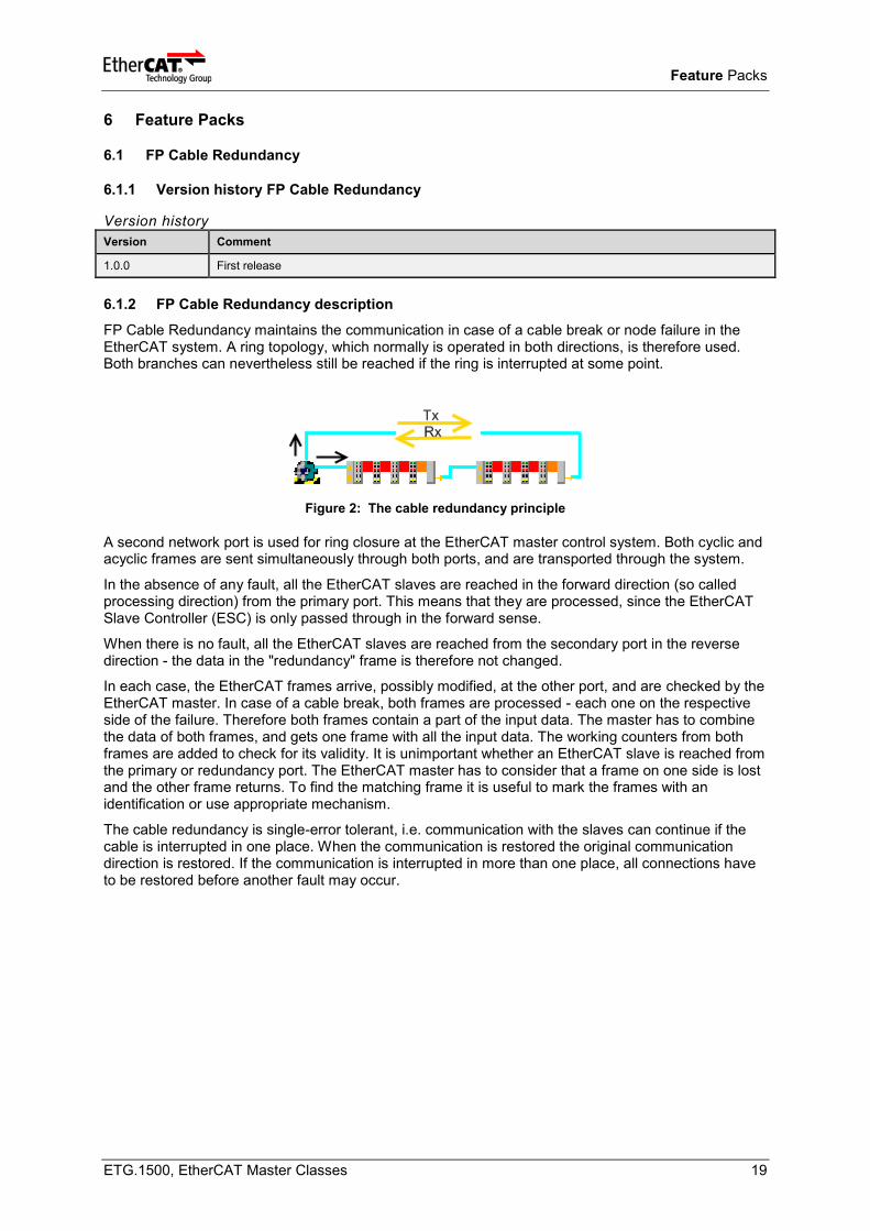
FP Cable Redundancy maintains the communication in case of a cable break or node failure in the EtherCAT system. A ring topology, which normally is operated in both directions, is therefore used. Both branches can nevertheless still be reached if the ring is interrupted at some point.
Figure 2: The cable redundancy principle
A second network port is used for ring closure at the EtherCAT master control system. Both cyclic and acyclic frames are sent simultaneously through both ports, and are transported through the system.
In the absence of any fault, all the EtherCAT slaves are reached in the forward direction (so called processing direction) from the primary port. This means that they are processed, since the EtherCAT Slave Controller (ESC) is only passed through in the forward sense.
When there is no fault, all the EtherCAT slaves are reached from the secondary port in the reverse direction - the data in the "redundancy" frame is therefore not changed.
In each case, the EtherCAT frames arrive, possibly modified, at the other port, and are checked by the EtherCAT master. In case of a cable break, both frames are processed - each one on the respective side of the failure. Therefore both frames contain a part of the input data. The master has to combine the data of both frames, and gets one frame with all the input data. The working counters from both frames are added to check for its validity. It is unimportant whether an EtherCAT slave is reached from the primary or redundancy port. The EtherCAT master has to consider that a frame on one side is lost and the other frame returns. To find the matching frame it is useful to mark the frames with an identification or use appropriate mechanism.
The cable redundancy is single-error tolerant, i.e. communication with the slaves can continue if the cable is interrupted in one place. When the communication is restored the original communication direction is restored. If the communication is interrupted in more than one place, all connections have to be restored before another fault may occur.
Feature Packs
ETG.1500, EtherCAT Master Classes 20
Table 2 lists features for the FP Cable Redundancy.
Table 2: FP Cable Redundancy specification
Function name Short description Category Feature ID Chapter
Basic Functions Basic functions to handle cable redundancy M FPCR_101 6.1.3
Diagnosis Functions Localization of cable break. M FPCR_102 6.1.4
Redundancy with Hot Connect
Combination of feature packs Hot Connect and Cable Redundancy
O FPCR_103 6.1.5
Redundancy with DC
Combination of FP Cable Redundancy with Distributed Clocks slaves
O FPCR_104 6.1.6
Implementation Aspect
Auto Increment Address changes in case of a cable break. Typically the same address exists twice. Therefore it is necessary to adjust the address in the frame sent on the primary port combined with disabling the command on the secondary port and vice versa.
Note
In ETG.8000Redundancy, [12], an example of the Cable redundancy is shown.
6.1.3 Basic Functions
Description
In case of cable break all types of EtherCAT communications (process data and mailbox protocols) shall be supported without any restrictions.
Handling of the following use cases:
Normal operation
Stay operational in case of cable break between two slaves
Stay operational in case of cable break between primary port and first slave
Stay operational in case of cable break between secondary port and last slave
Stay operational in case of cable fixed
Start/Stop (State change) in case of cable break
Adjustment of Auto Increment address in case of cable break
Frame loss in case of cable break (partner frame was not received)
Reference
In ETG.8000Redundancy, [12], an example of the Cable redundancy is shown.
6.1.4 Diagnosis Functions
Description
Localization of cable break shall be possible (Number of slaves on each port)
Support function to check link status of primary port and of secondary port.
6.1.5 Redundancy with Hot Connect
Description
Combination of feature packs Hot Connect and Cable Redundancy
Feature Packs
ETG.1500, EtherCAT Master Classes 21
6.1.6 Redundancy with DC
Description
Combination of feature pack Cable Redundancy and DC synchronization
Implementation Aspects
Special measures need to be taken for a combination of cable redundancy with Distributed Clocks slaves
6.2 FP Motion Control
6.2.1 Version history FP Motion Control
Version history
Version Comment
1.0.0 First release
6.2.2 FP Motion Control description
For EtherCAT drives two drive profiles, CiA 402 and SERCOS™, are defined. Within these profiles the support of a drive state machines and modes of operation are specified for example. Synchronization capabilities of the master are indispensible to support the drive profiles.
The drive profiles can be part of the master application.
Table 3 lists features for the FP Motion Control.
Table 3: FP Motion control specification
Function name Short description Category Feature ID Chapter
Drive Profile CiA402 Support Profile CiA402 M FPMC_101 6.2.3
Drive Profile SERCOS Support Profile SERCOS drive profile O FPMC_102 6.2.4
Synchronization with DC Support Synchronization with DC M FPMC_103 6.2.5
6.2.3 Drive Profile CiA402
Description
The CiA402 Drive Profile defined in IEC 61800-78-201 shall be supported.
For EtherCAT-based servo drives with CiA402 drive profile the Implementation Guideline ETG.6010 defines a common behaviour for the implementation of the drive profile. At least the requirements in this guideline (Control/Status word, Modes of Operation, supported objects etc.) shall be fulfilled.
References
IEC 61800-7-201
Mapping to EtherCAT in IEC 61800-7-301
ETG.6010
6.2.4 Drive Profile SERCOS
Description
The SERCOS™ Drive Profile defined in IEC 61800-7-204 should be supported.
References
SEROC Drive Profile in IEC 61800-7-204
Mapping to EtherCAT in IEC 61800-7-304
Feature Packs
ETG.1500, EtherCAT Master Classes 22
6.2.5 Synchronization with DC
Description
The master shall support synchronization with DC, as defined in chapter 5.13
Reference
see 5.13
6.3 FP Hot Connect
6.3.1 Version history FP Hot Connect
Version history
Version Comment
0.0.0 to be defined
6.3.2 FP Hot Connect description
The FP Hot Connect still needs to be defined.
6.4 FP External Synchronization
6.4.1 Version history FP External Synchronization
Version history
Version Comment
0.0.0 to be defined
6.4.2 FP External Synchronization description
The FP External Synchronization still needs to be defined.
6.5 FP EtherCAT Automation Protocol
6.5.1 Version history FP EtherCAT Automation Protocol
Version history
Version Comment
0.0.0 to be defined
6.5.2 FP EtherCAT Automation Protocol description
The FP EtherCAT Automation Protocol still needs to be defined.
Feature Packs
ETG.1500, EtherCAT Master Classes 23
6.6 FP Device Replacement
6.6.1 Version history FP Device Replacement
Version history
Version Comment
0.0.0 to be defined
6.6.2 FP Device Replacement description
The FP Device Replacement still needs to be defined.