3.1 Site Preparation ...................................................................................................................................................................... 4
4.2 Normal Operation .................................................................................................................................................................... 7
Terra Universal, Inc. • TerraUniversal.com • 800 S. Raymond Ave. • Fullerton, CA 92831 • TEL: (714) 578-6000 • FAX: (714) 578-6020 3
1.0 Introduction
This manual provides information on installing and operating your custom Terra Universal Roll-Up Door Pass-through. For more information, please visit https://www.terrauniversal.com/cleanroom-passthroughs/roll-up-door-pass-throughs.php.
IMPORTANT NOTICE
This pass-through is designed to transfer large equipment between controlled environments. Personnel should not attempt to use the pass-through as a means of entry or egress, as the controls are not designed to be operated from inside the pass-through.
2.0 Description
The Roll-Up Door Pass-Through features dual roll-up access doors made of segmented anodized aluminum. This door-type eliminates the need for door-swing clearance and allows large equipment (such as rolling racks) to be transferred in and out of the cleanroom.
Proprietary Notice This manual pertains to proprietary devices manufactured by Terra Universal, Inc. Neither this document nor any portion of it may be reproduced in any way without prior written permission from Terra Universal.
Terra Universal makes no warranties applying to information contained in this manual or its suitability for any implied or inferred purpose. Terra Universal shall not be held liable for any errors this manual contains or for any damages that result from its use.
Safety Notice A thorough familiarity with all operating guidelines is essential to safe operation of the product. Failure to observe safety precautions could result in poor performance, damage to the system or other property, or serious bodily injury or death. The following symbols are intended to call your attention to two levels of hazard involved in operation:
Cautions are used when failure to observe instructions could result in significant damage to equipment.
CAUTION
Warnings are used when failure to observe instructions or precautions could result in injury or death.
WARNING
The information presented here is subject to change without notice.
Terra Universal, Inc. • TerraUniversal.com • 800 S. Raymond Ave. • Fullerton, CA 92831 • TEL: (714) 578-6000 • FAX: (714) 578-6020 4
The electronic door interlock system prevents accidental cross-contamination by ensuring that only one door can be open at a time. The interlock system includes an override key-switch that will disable the interlock for repair or maintenance. During normal operation, the key-switch is turned to the NORMAL position. To prevent tampering with the interlock, the key can be removed and kept with designated personnel or stored in a lockbox. During installation or maintenance, the key-switch should be turned to the BYPASS position to keep both doors open at the same time. The Roll-Up Door Pass-Through is operated via a touch panel adjacent to each door of the pass-through. In addition to the open/close buttons, the touch panel includes an emergency stop function and a lockdown function. As an additional safety feature, the pass-through includes a pressure-sensitive safety switch that immediately stops the door from closing if the bottom edge of the door comes into contact with an object. Each pass-through door is monitored by two photoelectric sensors that send “stop” signals when the door is fully open or fully closed. The photoelectric sensors use lasers and reflective tape to monitor the position of the doors. The lasers emitted by the sensors must be properly aligned with the reflective tape in order for the doors to operate properly.
3.0 Installation
Do not remove the cross-braces inside the chamber until the pass-through is in its final position inside the wall cut-out, with all necessary adjustments and anchoring completed.
WARNING 3.1 Site Preparation A. Make sure that the pass-through will be placed on a level, stable surface, away from heat or chemicals that could damage
it.
B. Make a wall cut-out that will be ¼” wider and ¼” taller than the body of the pass-through. It is recommended that the cut-out be finished with the same materials as the cleanroom.
3.2 Unpacking
The Roll-Up Door Pass-Through is shipped with both doors in the fully open position to prevent damage during transit. Both doors will close once the unit is connected to power for the first time.
NOTE Carefully remove the crating from around the pass-through and visually inspect for damage, both inside and out. Be sure not to throw away any accessories or other important items with the packing material. Any damage should be reported according to the terms in the shipping agreement.
Figure 1. Safety Limit Switch along bottom edge of roll-up door
Figure 2. Photoelectric Sensor, mounted to the ceiling of the pass-through, with the laser striking the reflective tape
Terra Universal, Inc. • TerraUniversal.com • 800 S. Raymond Ave. • Fullerton, CA 92831 • TEL: (714) 578-6000 • FAX: (714) 578-6020 5
3.3 Pass-through Installation
Do not turn on the power source until all installation steps are complete and the unit has been carefully inspected for improper installation or damage to any of the components.
WARNING
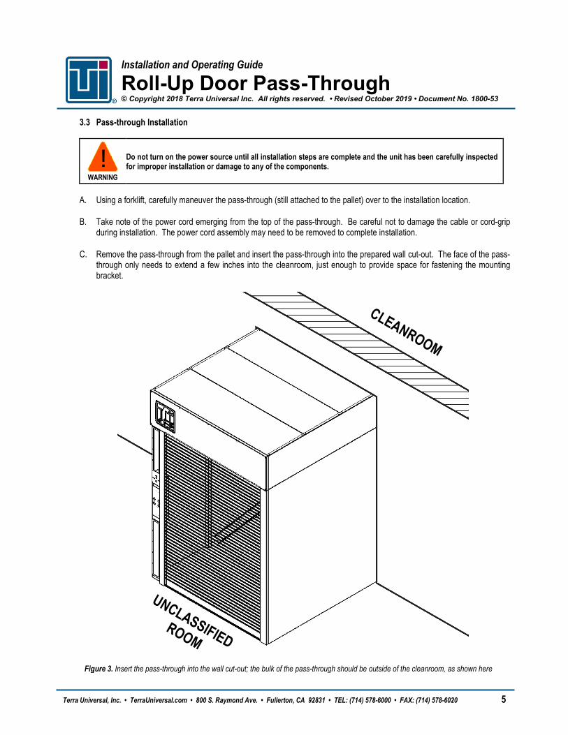
A. Using a forklift, carefully maneuver the pass-through (still attached to the pallet) over to the installation location.
B. Take note of the power cord emerging from the top of the pass-through. Be careful not to damage the cable or cord-grip during installation. The power cord assembly may need to be removed to complete installation.
C. Remove the pass-through from the pallet and insert the pass-through into the prepared wall cut-out. The face of the pass-through only needs to extend a few inches into the cleanroom, just enough to provide space for fastening the mounting bracket.
Figure 3. Insert the pass-through into the wall cut-out; the bulk of the pass-through should be outside of the cleanroom, as shown here
Terra Universal, Inc. • TerraUniversal.com • 800 S. Raymond Ave. • Fullerton, CA 92831 • TEL: (714) 578-6000 • FAX: (714) 578-6020 6
D. Check the entire unit for squareness by measuring diagonally across both faces of the unit and across the interior walls, floor, and ceiling. Compare diagonal measurements and ensure that they are equal. Be sure to check the chamber interior for squareness by measuring diagonally from the ceiling corner to the opposite floor corner, in both directions.
E. Position the top mounting bracket along the upper housing of the pass-through, against the wall surface. Before fastening, make sure that the mounting bracket covers the gap between the wall and the body of the pass-through.
F. While another person holds the mounting bracket in place, fasten the top bracket to the upper housing using ¾” self-tapping sheet metal screws.
G. Hold the two vertical brackets in place along the sides of the pass-through. Using the predrilled holes as a guide, drill through the wall of the main chamber. Be careful not to damage components on the other side of the chamber wall.
H. Use flat-headed bolts and nuts (not provided) to attach the mounting bracket to the pass-through walls (insert the flathead bolt from inside the pass-through; the nut should be on the outside). Cover the exposed nuts with stainless steel caps.
Figure 4. Cleanroom-side of the pass-through, with the three mounting brackets fastened around the body of the unit
(F) Fasten the mounting bracket to the top of the pass-through with screws
(G) Drill through the sides of the pass-through and (H)
insert flat-head bolts/nuts
(I) Fasten the mounting bracket to the wall surface with appropriate fasteners
Terra Universal, Inc. • TerraUniversal.com • 800 S. Raymond Ave. • Fullerton, CA 92831 • TEL: (714) 578-6000 • FAX: (714) 578-6020 7
I. Repeat Steps E through H for the mounting brackets on the opposite side of the wall. Once all mounting brackets are attached to the pass-through, fasten the mounting brackets to the wall surface using suitable fasteners (not provided).
J. Anchor the pass-through to the floor using the same bottom brackets that held the unit on the pallet.
K. Connect the unit to the power source, but do not turn on the power supply at this time.
L. Remove the cross-bracing by loosening the screws at each end and carefully pulling the ends of the bracing out of position. Take care not to damage the stainless steel surfaces inside the pass-through.
M. Apply a suitable sealant along the edges of the mounting brackets, as well as along any interior or exterior seams as determined by the end-user.
4.0 Operation
4.1 Initial Start-Up
A. Prior to turning on the power source, make sure that both override key-switches are turned to the NORMAL position.
B. Clear any obstructions from the path of the doors.
C. Turn on the power source. Both roll-up doors will automatically close.
Once the doors are fully closed, the unit is ready for use. If either of the doors malfunctions while closing, press the malfunctioning door’s RESET button for one second and then release. The door will return to the fully closed position.
4.2 Normal Operation
Roll-up doors are rated at a maximum of twelve (12) open/close cycles per hour, depending on ambient conditions. Motors are equipped with a thermal overload circuit to protect them from overuse; however, continuous use at high temperatures may lead to premature motor failure.
CAUTION During normal operation, the two override key-switches should remain in the NORMAL position with the keys removed, stored in a secure location. In this mode, the electronic interlock is activated anytime that one of the roll-up doors is opened, causing the opposite-side door to be locked in the closed position. Only one roll-up door can be open at a time, which protects the controlled environment from sudden cross-contamination.
The control panel functions are as follows:
UP Button Press once to open the roll-up door. DOWN Button Press once to close the roll-up door.
LOCK Button Press once to close the pass-through door and lock both doors in the closed position. Disable the Lock Down function by pressing the LOCK button three times in succession. An internal alarm will beep as long as the Lock Down function is activated.
Terra Universal, Inc. • TerraUniversal.com • 800 S. Raymond Ave. • Fullerton, CA 92831 • TEL: (714) 578-6000 • FAX: (714) 578-6020 8
E-STOP Button Press once to open the pass-through door and lock it in the open position. All status indicator lights will blink alternating between red and green until E-STOP is disabled. Disable the Emergency Stop function by pressing the E-STOP button three times in succession.
Make sure that both doors are clear of obstructions before pressing the LOCK button. The safety limit switch does not work when using the lockdown function.
WARNING 4.3 Manual Override
Overriding the electronic interlock system will put the cleanroom at risk of contamination. This mode should only be used for maintenance purposes and should be followed by decontamination of the cleanroom.
WARNING The override key-switches allow operators to disable the electronic interlock system, opening the roll-up door even if the opposite-side door is already open. This mode is useful when transferring new pieces of equipment or large amounts of material into the cleanroom, particularly during a new cleanroom buildout. To raise both doors to the fully open position: A. Turn both key-switches to the BYPASS position.
B. Remove the keys from the key-switches to prevent tampering with the interlock system during maintenance.
To return both doors to the closed position: A. One at a time, turn the key-switches to the NORMAL position, allowing the door to fully close before moving on to the next
door.
B. Remove the key from the key-switch to prevent tampering with the interlock system during normal operation.
The door may behave unexpectedly if any control panel buttons were pressed while the system was in BYPASS mode. Press the RESET button to halt the door movement and the door will close when RESET is released.
NOTE 4.4 Optional Air Shower If equipped with the optional Air Shower system, the air shower cycle will activate when the cleanroom-side door closes. Micro-filtered air will stream through the nozzles on either side of the chamber, blowing off particles that have been deposited on the materials and equipment being transferred. Return vents on the ceiling of the chamber allow the air to recirculate through the two blowers, each equipped with an inlet ULPA filter. The air shower cycle lasts for 60 seconds by default. Users can adjust the cycle time via a DIP switch on the circuit board within the upper housing (see Section 5.2 for instructions on accessing the circuit board).
Terra Universal, Inc. • TerraUniversal.com • 800 S. Raymond Ave. • Fullerton, CA 92831 • TEL: (714) 578-6000 • FAX: (714) 578-6020 9
DIP Switch Settings for Air Shower Cycle Timer
10-Second Cycle
1 2 3
Figure 6. DIP Switch settings for 60 second cycle
30-Second Cycle
1 2 3
60-Second Cycle
1 2 3
Air Shower Disabled
1 2 3
5.0 Maintenance
Take care when cleaning to avoid excessive spraying, particularly when using conductive liquids, which can damage the electronic connections and components. Cleaning should be accomplished through controlled application of cleaning agents or pre-dampened wipers.
CAUTION
Always check material compatibility before selecting a cleaning agent.
NOTE 5.1 Cleaning Stainless steel should be cleaned with alcohol (or similar cleaning agent), used to dampen a non-shedding wiper. In general, Terra Universal’s Roll-Up Door Pass-Through features no user-serviceable parts and requires no maintenance aside from periodic cleaning and ULPA filter replacement (if equipped with an air shower). Operators are responsible for inspecting the general condition of the unit before each use. Any worn or damaged component should be thoroughly examined and a safety evaluation should be performed before placing the unit back into service. When the pass-through is used in a cleanroom environment, Terra recommends use of knitted polyester wipers or spun-lace, non-woven blends of cellulose and polyester manufactured and packaged specifically for cleanroom use. These products are manufactured under tightly controlled conditions that restrict the use of binders or chemical treatments that can outgas, and cleanroom packaging and strict lot control ensure optimal cleanliness. Less critical environments (ISO 6 – 8 / Class 1000 – 100,000) generally tolerate more absorbent materials made of 100% cotton twill or cellulose.
Terra Universal, Inc. • TerraUniversal.com • 800 S. Raymond Ave. • Fullerton, CA 92831 • TEL: (714) 578-6000 • FAX: (714) 578-6020 10
Clean surfaces with clean, lukewarm water with or without a mild, non-abrasive detergent. In critical cleanroom applications, DI water may be required. For thorough, repeatable results, avoid cleaning with a circular motion, which rubs dirt or grit into the surface. Using mild pressure, wipe in one direction, from top to bottom or side to side, in slightly overlapping stokes. Fold the wiper between strokes, and replace with a clean wiper often.
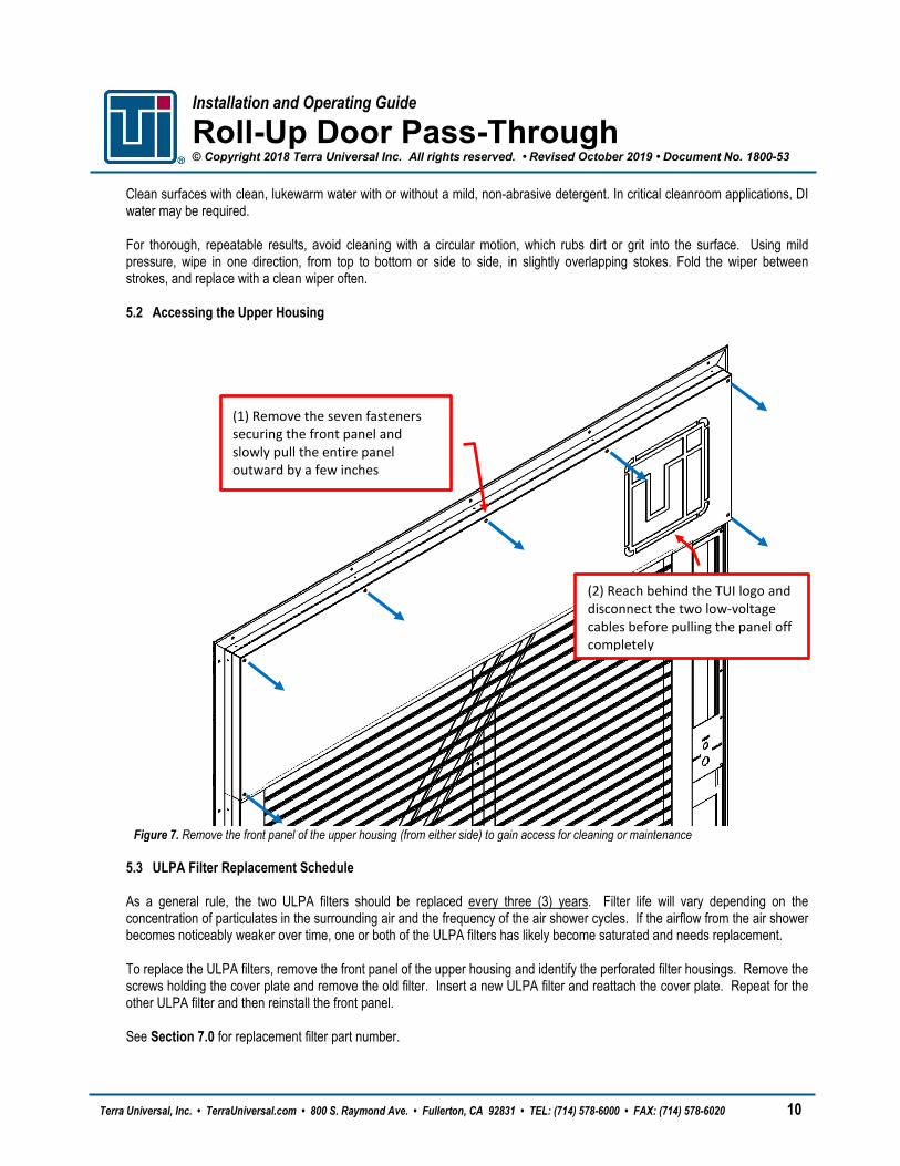
5.2 Accessing the Upper Housing
Figure 7. Remove the front panel of the upper housing (from either side) to gain access for cleaning or maintenance
5.3 ULPA Filter Replacement Schedule As a general rule, the two ULPA filters should be replaced every three (3) years. Filter life will vary depending on the concentration of particulates in the surrounding air and the frequency of the air shower cycles. If the airflow from the air shower becomes noticeably weaker over time, one or both of the ULPA filters has likely become saturated and needs replacement. To replace the ULPA filters, remove the front panel of the upper housing and identify the perforated filter housings. Remove the screws holding the cover plate and remove the old filter. Insert a new ULPA filter and reattach the cover plate. Repeat for the other ULPA filter and then reinstall the front panel. See Section 7.0 for replacement filter part number.
(1) Remove the seven fasteners securing the front panel and slowly pull the entire panel outward by a few inches
(2) Reach behind the TUI logo and disconnect the two low-voltage cables before pulling the panel off completely
Terra Universal, Inc. • TerraUniversal.com • 800 S. Raymond Ave. • Fullerton, CA 92831 • TEL: (714) 578-6000 • FAX: (714) 578-6020 11
5.4 Door Open/Close Limit Adjustment Each roll-up door includes a tension adjustment that changes open/close limits for each door. A tool is provided for this purpose, but an Allen wrench will also work. A. With the door in the closed position, remove the front access
panel (see Section 5.2) to access the door motor mechanism. On the right-hand side of the door motor, locate the two hex-head adjustment screws.
B. Use the tool to turn the DOWN screw to adjust the gap
between the door’s leading edge and the floor. A gap of less than ¼” is recommended to minimize leakage.
C. Repeat this procedure with the door in the open position,
adjusting the UP screw until satisfied with the positioning of the door.
D. Check the alignment of the photoelectric sensor with the
reflective tape after adjusting the doors. If necessary, replace the tape according to the instructions in Section 5.5.
5.5 Reflective Tape Replacement The reflective tape on the inside of the roll-up doors should be replaced if the reflective surface is damaged, the tape is peeling off, or if the laser is no longer in alignment. A. With the door in the closed position, remove the old tape being
struck by the laser. Take care not to damage the door surface.
B. Use a mild detergent to remove any adhesive residue.
C. Check the gap along the bottom of the door for correct positioning. If needed, adjust the door by following the instructions in Section 5.4.
D. Cut a strip of Terra-supplied reflective tape 1-½” long and stick the tape onto the door surface, centered on the laser beam.
E. Open the door and repeat Steps A through D for the next piece of tape struck by the laser.
Figure 8. Tension adjustment tool in position
Figure 9. Tension adjustment screws, viewed from above
Terra Universal, Inc. • TerraUniversal.com • 800 S. Raymond Ave. • Fullerton, CA 92831 • TEL: (714) 578-6000 • FAX: (714) 578-6020 12
6.0 Troubleshooting
Problem: The system has malfunctioned.
Possible Solution(s): Check to make sure that the manual override key-switches are turned to the NORMAL position and then reset the doors to the closed position by pressing one or both of the RESET buttons.
Problem: One or both of the pass-through doors will not close.
Possible Solution(s): Check to make sure that the manual override key switches are turned to the NORMAL position and try again. If the problem persists, press the corresponding RESET button to close the doors.
Problem: One or both of the pass-through doors will not open.
Possible Solution(s): Try disabling the Lock Down function by pressing LOCK three times in succession. Turn the corresponding key-switch to the BYPASS position. If the problem persists, press the RESET button to reset the door motor.
Problem: The pass-through door does not move or has stopped moving in the middle of opening/closing.
Possible Solution(s): The door motor may have overheated. Wait approximately 30 minutes to an hour for the motor to cool down before trying again. If the door was in the middle of opening/closing, it will resume its process automatically once the motor has cooled down.
Problem: The doors do not stop at the proper open and closed positions.
Possible Solution(s): Check the reflective tape on the inside of the doors and reapply if it has fallen off (See Section 5.5). If the problem persists, the photo sensor may need to be recalibrated. Contact Terra Universal for further instruction.
Problem: The touch panel does not respond when any button is pressed.
Possible Solution(s): Check to make sure that the manual override key switches are turned to the NORMAL position. Press and hold one or both of the RESET buttons. If the problem persists, the system may have crashed. Disconnect the unit from power, wait two minutes, and then reconnect the unit.
Problem: The system is not responding. The TUI logo does not light up.
Possible Solution(s): Check the unit’s power source. If the power supply is intact, the system’s main circuit breaker may have been tripped. Access the circuit breaker in the upper housing by following the instructions in Section 5.2. Check for any blown fuses, any visible damage to the main circuit board, or any visible damage to the other components.
Terra Universal, Inc. • TerraUniversal.com • 800 S. Raymond Ave. • Fullerton, CA 92831 • TEL: (714) 578-6000 • FAX: (714) 578-6020 13
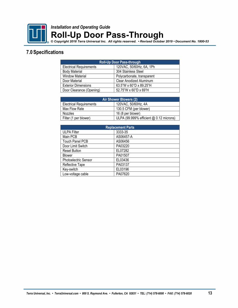
7.0 Specifications
Roll-Up Door Pass-through Electrical Requirements 120VAC, 50/60Hz, 6A, 1Ph Body Material 304 Stainless Steel Window Material Polycarbonate, transparent Door Material Clear Anodized Aluminum Exterior Dimensions 63.5”W x 60”D x 89.25”H Door Clearance (Opening) 52.75”W x 60”D x 69”H
Air Shower Blowers (2)
Electrical Requirements 120VAC, 50/60Hz, 4A Max Flow Rate 130.5 CFM (per blower) Nozzles 16 (8 per blower) Filter (1 per blower) ULPA (99.999% efficient @ 0.12 microns)
Terra Universal, Inc. • TerraUniversal.com • 800 S. Raymond Ave. • Fullerton, CA 92831 • TEL: (714) 578-6000 • FAX: (714) 578-6020 14
8.0 Warranty
Products Manufactured by Terra: Terra Universal, Inc., warrants products that it manufactures to be free from defects for a period of 12 months for parts and 90 days for labor, commencing from the date of shipment. This limited warranty covers parts and labor, but not transportation and insurance charges. Terra’s sole responsibility is to repair or replace, at its option, any part of the product that proves defective or malfunctioning during this time limit. In some cases, components incorporated in Terra Universal products are covered by additional warranties from component manufacturers; obtain specific information from Terra sales representatives. Repairs may be completed by 3rd party service agents approved by Terra Universal. Terra Universal reserves the rights to limit this warranty based on a service agent’s travel, working hours, the site’s entry restrictions and unobstructed access to serviceable components of the product. This warranty is void if the equipment is abused or modified by the customer, is operated outside Terra’s operating instructions or specifications, or is used in any application other than that for which it is specified. This warranty does not include routine maintenance or service procedures, breakage of quartz baths after 60 days, shipping damage, nor damage from misuse, intentional or unintentional abuse, neglect, natural disasters, or acts of God. Products Manufactured by Others: Terra Universal, Inc., warrants that, to the best of its ability, Terra’s representations of products that are manufactured by others reflect the manufacturer’s representations, subject to change without notice. Sole warranty for these products is the original manufacturer’s warranty that is passed forward to the purchaser and constitutes the customer’s sole remedy for these products. Detailed warranties for distributed products are available through Terra sales representatives. Freight Shortage or Damage: Upon receipt of any equipment from Terra Universal, Inc., customer shall immediately unpack and inspect for damage or shortage. The customer shall not accept a damaged package or a short shipment until the carrier makes a "damage or shortage" notation on both the carrier's and customer's copy of the freight bill or delivery receipt. Service title passes when the shipment is loaded, so customer is responsible for filing and collecting a freight claim. Any replacement products must be ordered and paid for separately. For Terra's "Policy and Procedures for Returning Goods," see Terra's Internet site: www.TerraUniversal.com. Generally, customers can improve the chance of collecting on a freight claim by following these procedures: 1) formally requesting that the carrier inspect the shipment immediately upon suspecting damage or shortage to verify condition; 2) notifying the carrier upon discovery of concealed damage and requesting an inspection within 15 days of receipt, both in person or phone and following up via mail; 3) keeping the shipment as intact as possible, including retaining original packaging materials and keeping the product as close to the original receiving location as possible; 4) holding salvage for disposition by the carrier. All Claims: Terra Universal expressly disclaims all other warranties, expressed or implied or implied by statute, including the warranties of merchantability or fitness for intended use. Terra Universal is not responsible for consequential or incidental damages arising out of the purchase or use of the products supplied by Terra Universal. Terra Universal is not liable for damage to facilities, other equipment, products, property or personnel of others, or of their agents, suppliers, or affiliated parties, which is caused or alleged to have been caused by products supplied by Terra Universal. In any event or series of events, Terra Universal’s total liability for any and all damages whatsoever is limited to the lesser of the actual damages or the original invoice cost of the items alleged to have caused the damage. The customer’s sole and exclusive remedy for any cause of action whatsoever is repair or replacement of the non-conforming products or refund of the actual purchase price, at the sole option of Terra Universal. All claims must be made in writing within 90 days of the date the product was shipped. Any claims not made within this time limit shall be deemed waived by the customer. Terra Universal is not responsible for any additional costs of repair caused by poor packaging or in-shipment damage during return. Warranty Returns: All warranty returns must be authorized in advance by Terra Universal and approved under an RMA. Unless approved in advance for good reason, all returns must be in original condition, including all manuals, and must be packaged in original packaging materials. All returned goods are to be shipped to Terra Universal, freight prepaid at customer’s expense. See Terra’s “Policy and Procedure for Returned Goods.” Terra Universal Warranty Policy: https://www.terrauniversal.com/warranty/