Sika thermoformed plastic formliners are used for texturing tilt- up, cast-in-place or precast architectural concrete. Sheets of formliner attach to the formwork or casting bed prior to placing the concrete. Following placement and normal curing time, the formwork and formliner are stripped, leaving a textured concrete surface. Sika formliners are rigid thermoformed polymer alloy sheets, engineered for lightweight and ease of handling at the job site. More than 80 standard patterns are available. Custom designs will be considered. Call Sika St. Louis with specific details. All patterns are available in at least two use ranges: UNI-CAST ® - Single-use thermoformed plastic formliner, designed for tilt-up or cast in place jobs where the formliner will only be used once. MULTI-CAST ® - Intermediate-use thermoformed plastic formliner designed for 2-10 uses under normal job site conditions. Some formliner patterns are available in a third usage range: DURA-CAST ® - High-use thermoformed plastic formliner, designed for 10-25 uses under normal job site conditions. Significantly more uses can be expected in precast applications. Sika UNI-CAST ® , MULTI-CAST ® and DURA-CAST ® formliners are interchangeable on the same job. Allowances need to be made for thickness differences between formliner grades. Formliner sheets are trimmed straight and square to a nominal 4′ x 10′ size (see Catalog for actual dimensions). 1/8 FORMLINER – INSTALLATION DOCUMENT 08/2014 ARCHITECTURAL CONCRETE FORMLINERS INSTALLATION GUIDE AND SPECIFICATION DATA
Transcript
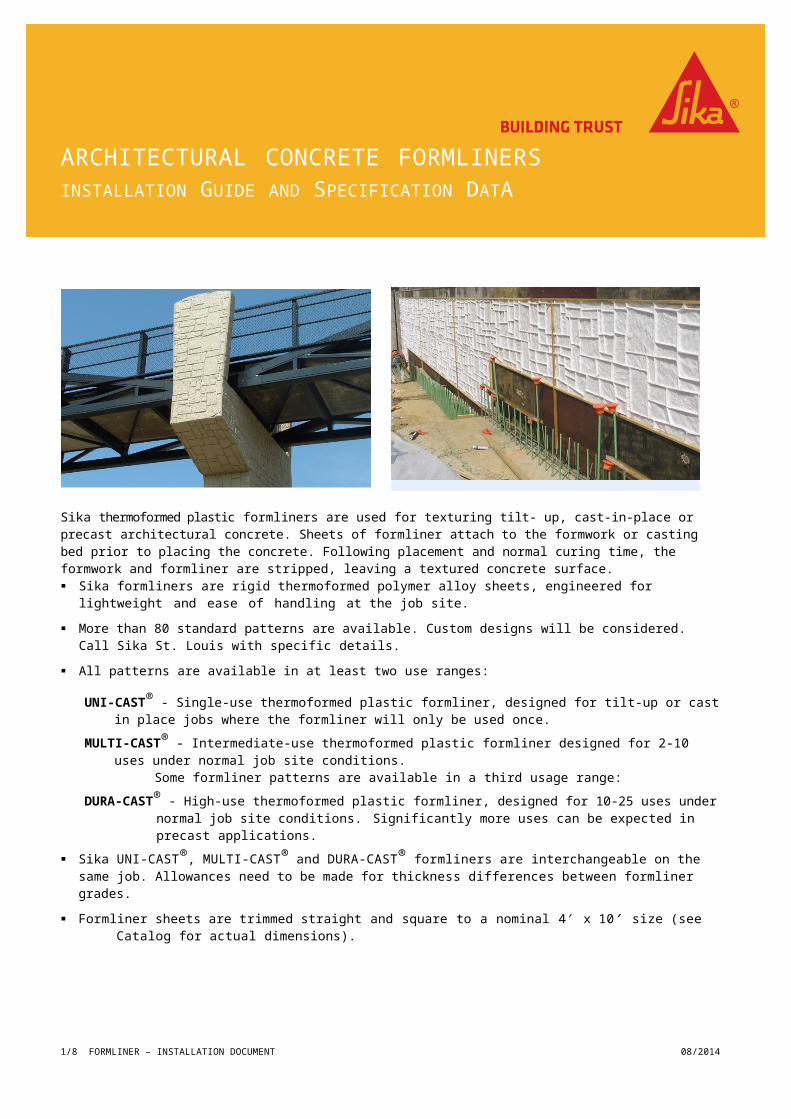
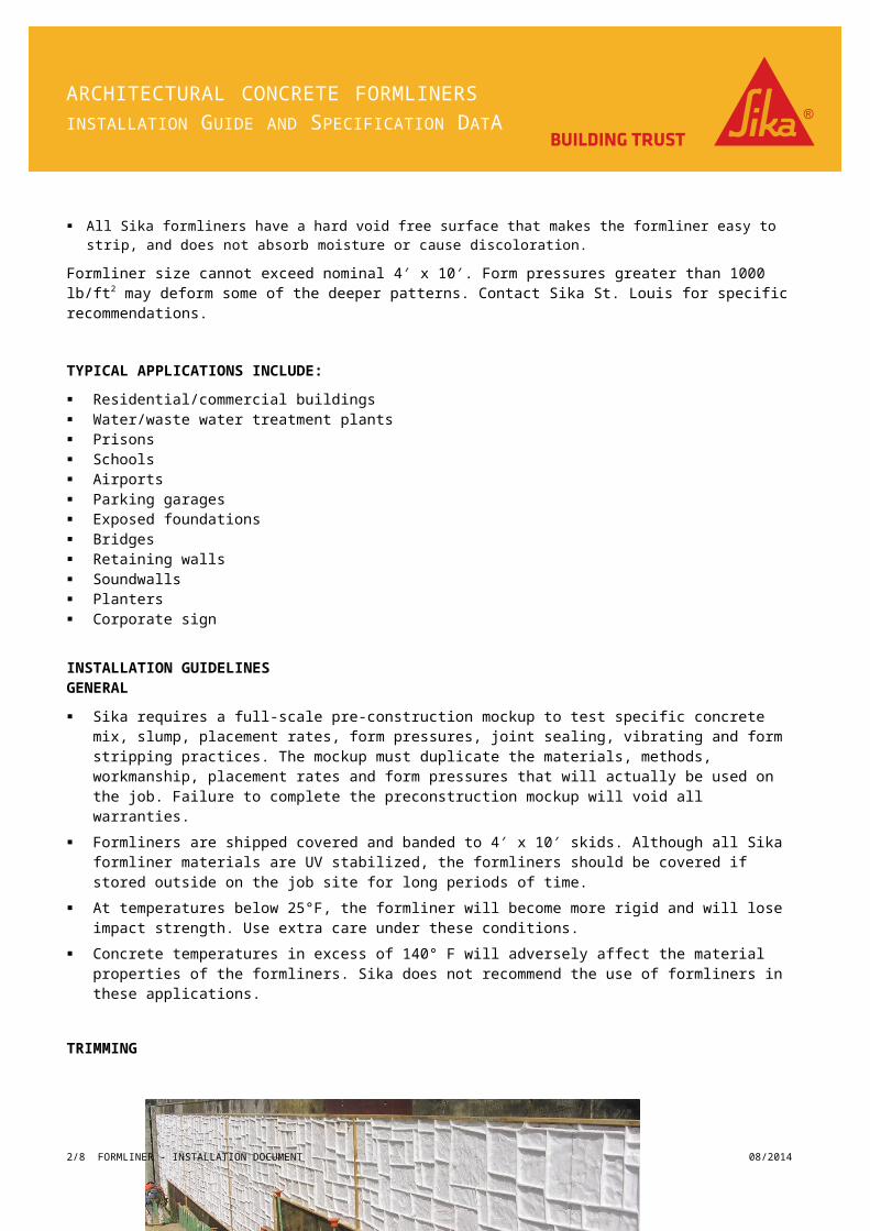
Sika thermoformed plastic formliners are used for texturing tilt- up, cast-in-place or precast architectural concrete. Sheets of formliner attach to the formwork or casting bed prior to placing the concrete. Following placement and normal curing time, the formwork and formliner are stripped, leaving a textured concrete surface. Sika formliners are rigid thermoformed polymer alloy sheets, engineered for lightweight and ease of handling at the job
site.
More than 80 standard patterns are available. Custom designs will be considered. Call Sika St. Louis with specific details.
All patterns are available in at least two use ranges:
UNI-CAST® - Single-use thermoformed plastic formliner, designed for tilt-up or cast in place jobs where the formliner will only be used once.
MULTI-CAST® - Intermediate-use thermoformed plastic formliner designed for 2-10 uses under normal job site conditions.Some formliner patterns are available in a third usage range:
DURA-CAST® - High-use thermoformed plastic formliner, designed for 10-25 uses under normal job site conditions. Significantly more uses can be expected in precast applications.
Sika UNI-CAST®, MULTI-CAST® and DURA-CAST® formliners are interchangeable on the same job. Allowances need to be made for thickness differences between formliner grades.
Formliner sheets are trimmed straight and square to a nominal 4′ x 10′ size (see Catalog for actual dimensions).
All Sika formliners have a hard void free surface that makes the formliner easy to strip, and does not absorb moisture or cause discoloration.
Formliner size cannot exceed nominal 4 x 10 . Form pressures greater than 1000 lb/ft′ ′ 2 may deform some of the deeper patterns. Contact Sika St. Louis for specific recommendations.
TYPICAL APPLICATIONS INCLUDE:
Residential/commercial buildings Water/waste water treatment plants
1/6 FORMLINER – INSTALLATION DOCUMENT 08/2014
ARCHITECTURAL CONCRETE FORMLINERSINSTALLATION GUIDE AND SPECIFICATION DATA
ARCHITECTURAL CONCRETE FORMLINERSINSTALLATION GUIDE AND SPECIFICATION DATA
Sika requires a full-scale pre-construction mockup to test specific concrete mix, slump, placement rates, form pressures, joint sealing, vibrating and form stripping practices. The mockup must duplicate the materials, methods, workmanship, placement rates and form pressures that will actually be used on the job. Failure to complete the preconstruction mockup will void all warranties.
Formliners are shipped covered and banded to 4 x 10 skids. Although all Sika formliner materials are UV stabilized, ′ ′the formliners should be covered if stored outside on the job site for long periods of time.
At temperatures below 25°F, the formliner will become more rigid and will lose impact strength. Use extra care under these conditions.
Concrete temperatures in excess of 140° F will adversely affect the material properties of the formliners. Sika does not recommend the use of formliners in these applications.
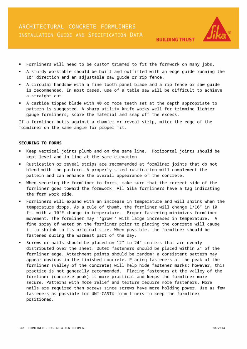
TRIMMING
Formliners will need to be custom trimmed to fit the formwork on many jobs.
A sturdy worktable should be built and outfitted with an edge guide running the 10 direction and an adjustable saw ′guide or rip fence.
A circular handsaw with a fine tooth panel blade and a rip fence or saw guide is recommended. In most cases, use of a table saw will be difficult to achieve a straight cut.
A carbide tipped blade with 40 or more teeth set at the depth appropriate to pattern is suggested. A sharp utility knife works well for trimming lighter gauge formliners; score the material and snap off the excess.
If a formliner butts against a chamfer or reveal strip, miter the edge of the formliner on the same angle for proper fit.
SECURING TO FORMS
Keep vertical joints plumb and on the same line. Horizontal joints should be kept level and in line at the same elevation.
Rustication or reveal strips are recommended at formliner joints that do not blend with the pattern. A properly sized rustication will complement the pattern and can enhance the overall appearance of the concrete.
When securing the formliner to forms, make sure that the correct side of the formliner goes toward the formwork. All Sika formliners have a tag indicating the form work side.
2/6 FORMLINER - INSTALLATION DOCUMENT 08/2014
ARCHITECTURAL CONCRETE FORMLINERSINSTALLATION GUIDE AND SPECIFICATION DATA
Formliners will expand with an increase in temperature and will shrink when the temperature drops. As a rule of thumb, the formliner will change 1/16″ in 10 ft. with a 10°F change in temperature. Proper fastening minimizes formliner movement. The formliner may ‘‘grow’’ with large increases in temperature. A fine spray of water on the formliner prior to placing the concrete will cause it to shrink to its original size. When possible, the formliner should be fastened during the warmest part of the day.
Screws or nails should be placed on 12″ to 24″ centers that are evenly distributed over the sheet. Outer fasteners should be placed within 2″ of the formliner edge. Attachment points should be random; a consistent pattern may appear obvious in the finished concrete. Placing fasteners at the peak of the formliner (valley of the concrete) will help hide fastener marks; however, this practice is not generally recommended. Placing fasteners at the valley of the formliner (concrete peak) is more practical and keeps the formliner more secure. Patterns with more relief and texture require more fasteners. More nails are required than screws since screws have more holding power. Use as few fasteners as possible for UNI-CAST® form liners to keep the formliner positioned.
Screws: Easy to use, screws have the best holding power and are easily removed. Bugle head self- drilling and tapping screws #8-18 x 1″ are the minimum size recommended. Self-drilling and tapping, the flat head fits flush with the formliner, and may be used for steel or wood forms. A screw gun with adjustable torque setting is also recommended.
Nails: Easy to install, nails feature good holding power. 7D or larger cement coated or ring shanked nails are recommended. A pneumatic nailer should be used with a pressure regulator.
Staples: Small staples (approx. 1/8″ wide x 3/8″ deep) are easy to use and easily hidden in the pattern. They have much less holding power and should be used on 6″ - 12″ centers. Use a pneumatic stapler with pressure regulator.
Pop rivets: Feature good holding power on metal forms but require more work than self-drilling screws.
WOODEN DOWELS: On tilt-up or precast jobs where the formliner is attached to the concrete casting bed, screw or nail the formliner to 1/2″ wooden dowels inserted in the concrete. The dowels are easy to drill out and patch when the job is complete.
CONSTRUCTION ADHESIVE: On tilt-up concrete applications, construction adhesive may be used to adhere formliners to concrete slabs. The concrete and the formliner must be clean and dry during installation. After initial installation, keep the concrete surface dry, as moisture between the plastic and the concrete can break the adhesive bond. Sealing at the formliner joints will aid in maintaining this bond.
DOUBLE-COATED FOAM TAPE: On tilt-up concrete applications, double-coated foam tape provides an easy way to secure the formliner to the casting bed. On most patterns, the tape should be centered on the formliner seams. Carpet tape 1/32″ - 1/16″ is recommended. Both formliner and concrete must be clean and dry.
BACKUP STRIPS: To prevent deflection from the pressure of freshly placed concrete, some formliner patterns will require additional support. Generally, patterns with ribs wider than 1 1/2″, or a depth of 1 1/2″ or greater should have back-up strips installed (see Sika literature for recommendations). The need for back-up strips should be confirmed from the mockup. Wood or styrene foam insulation board may be effective back-up strip materials.
SEALING
All formliner joints and tie holes should be sealed to prevent localized water loss and subsequent discoloration of the concrete. Grout leakage will make stripping difficult and may damage the formliner.
Neutral cure silicone sealant is recommended for cast-in-place concrete. Once cured, it is flexible, has good adhesion and won’t discolor or stick to the concrete.
FORM BOLTS, TIES AND BAR SUPPORTS
3/6 FORMLINER - INSTALLATION DOCUMENT 08/2014
ARCHITECTURAL CONCRETE FORMLINERSINSTALLATION GUIDE AND SPECIFICATION DATA
Tie spacing should be a multiple of the formliner pattern repeat.
Tight fitting holes may be drilled or cut with a hole saw.
Reinforced fiberglass rod ties work well with architectural formliners. After stripping, the rods are snapped off and ground flush with the concrete. Patching and filling of holes is eliminated.
Ties located in the ‘‘valley’’ of the concrete may be less obvious. Patching tie holes located in the ‘‘peak’’ of the concrete is easier.
Bar supports or spacers should always rest against the portion of the formliner that is in contact with the formwork. The leg spacing of the bar supports should match the pattern repeat of the formliner.
Supports and spacers should be plastic or plastic tipped to minimize rust stains on the finished concrete.
Some deeper patterns may deform when walked on in precast and tilt-up applications. When placing the rebar mat, workers should walk on strips of 1/4″ plywood to distribute the load on the formliner. The thin plywood strips are flexible enough to pull out through the rebar mat prior to concrete placement. The concrete itself distributes the load during placement. If permissible, walk on the reinforcing steel rather than the formliner surface.
RELEASE AGENTS
Sika formliners are made from rigid non-absorbing materials that will not bond to concrete.
Formliners should be prepared with Sika Greenstreak Form Release 7000 just prior to concrete placement. Proper use of Form Release 7000 will aid in stripping of forms, improve the surface appearance of the concrete, and speed clean-up between concrete placements. Other form release agents may cause cracking and degradation of the formliner material with subsequent failure. Although Sika UNI-CAST® single-use formliners do not require the use of a form release agent, it is still suggested to improve the surface appearance of the concrete.
Apply form release agent at recommended rates. Over-application may produce surface voids.
CONCRETE MIX DESIGN
For uniformity of color and texture, use one concrete supplier, making sure that all concrete materials come from the same sources.
Recommended slump is 4 to 6 inches. Higher slump improves concrete consolidation in pattern details.
Avoid overly sandy or high air-entrained mixes, as they tend to be ‘‘sticky’’ and can promote bug holes.
For ribbed textures, coarse aggregate size should be smaller than the width of the rib. Oversize aggregates can cause honeycombing and brittleness of the concrete ribs.
Use an elephant trunk or tremie during concrete placement to minimize aggregate segregation. Dropping fresh concrete long distances directly against the formliner may cause surface abrasion or deformation of the formliner pattern, resulting in an undesirable concrete appearance.
Pumping concrete into the forms from the bottom of a wall will generally reduce air voids in the surface of the concrete. This method will also raise the form pressures significantly, which may damage the formliner.
Proper use of a water reducing admixture (plasticizer) in the concrete mix will minimize air voids. Concrete placement rate may have to be reduced to keep form pressures at an acceptable level.
High concrete placement rates may create excessive form pressures, which can deform or damage the formliner. High concrete placement rates may also cause excessive air voids.
4/6 FORMLINER - INSTALLATION DOCUMENT 08/2014
ARCHITECTURAL CONCRETE FORMLINERSINSTALLATION GUIDE AND SPECIFICATION DATA
THE FOLLOWING ACI COMMITTEE REPORTS ARE RECOMMENDED:
ACI 117; ‘‘Specifications for Tolerances for Concrete Construction and Materials and Commentary’’
ACI 303R; ‘‘Guide to Cast-in-PlaceArchitectural Concrete Practice’’
ACI 309 CH.7; ‘‘Guide forConsolidation of Concrete’’
ACI 347 CH.5; ‘‘Guide to Formwork for Concrete’’
Concrete lifts should not exceed 24 inches. Thoroughly vibrate concrete to achieve good consolidation, eliminate lift lines, and to minimize air voids. External vibrators can loosen the formliner from the formwork; internal vibrators are normally used. Contact between the vibrator and the formliner may damage the formliner. Under and over vibration may also cause defects in the surface of the concrete.
Footprints, standing water, and dirt/debris should be removed from the formliner before placing concrete for precast and tilt-up concrete applications.
Elevated temperatures encountered with heated curing beds may harm the formliner. Contact Sika (St. Louis Sales Office) for specific recommendations.
STRIPPING AND CLEAN-UP
The force required in stripping forms with formliners is greater than smooth formwork. When applying the extra force needed, care should be taken so that the textured surface is not damaged.
Formwork should be broken back after a minimum of 12 hours and removed preferably within 24 hours of concrete placement. Extending the time from placement to stripping can increase the force required.
Begin stripping at the top of the formwork. Separate the form from the concrete slightly. Hold in this position for several minutes to allow the induced stress in the form to diminish. Continue to separate the formwork from the concrete in stages until final separation is achieved.
Sika formliners are easily cleaned with household detergent and a stiff brush.
FINAL FINISHING
Rubbing: Seams and forming defects may be removed with a stone while the concrete is green.
Sandblasting: Many jobs call for sandblasting to roughen the surface and expose aggregate color. Sandblasting may also hide seams and forming defects but will not hide discoloration caused by grout leakage.
Patching: When patching tie holes or more serious forming defects, a close color match is critical. Use the same materials used in the original mix and perform several trial runs before beginning work on the structure. If in doubt, hire a consultant. Bad patches look worse than the original problem.
AVAILABILITY AND COST
Availability: Sika formliners are distributed worldwide through an extensive network of concrete forming and accessory dealers. Contact Sika (St. Louis Sales Office) for the nearest product dealer.
Lead Time: Lead times will vary with order quantity, pattern, and production schedule. Some popular patterns are kept in stock for immediate delivery. Allow one to two weeks for most orders, and six weeks for custom patterns.
Price: Price will vary with order quantity, pattern, and choice of UNI-CAST®, MULTI-
CAST® or DURA-CAST® grade.
5/6 FORMLINER - INSTALLATION DOCUMENT 08/2014
ARCHITECTURAL CONCRETE FORMLINERSINSTALLATION GUIDE AND SPECIFICATION DATA
TECHNICAL SERVICES Sika product engineers are available for consultation during design, specification, and product installation.
Additional information, product brochures, 3-part CSI formatted specification, and technical notes are available upon request.
Formliner Weight Range (lb/ft2) 0.41 - 0.82 0.33 - 0.81
Fastener Pull Through Strength(lb/fastener/in of material thickness)
2056 1263
Fastener Fatigue(# of cycles to failure @ 165 lb/fastener)
173 1
6/6 FORMLINER - INSTALLATION DOCUMENT 08/2014
Sika Corporation - US 201 Polito Avenue Lyndhurst, NJ 07071 United States Usa.Sika.com
For More Information Contact Sika - St. Louis Sales Office 3400 Tree Court Industrial Blvd. 63122, St. Louis, MO United States www.USA.Sika.com Phone: 1-800-325-9504 Fax: 800-551-5145