HELIA , 30 , Nr. 46, p.p. 103-132, (2007) UDC 633.854.78:631.527.85 DOI: 10.2298/HEL0746103D STEAM REFORMING OF SUNFLOWER OIL FOR HYDROGEN GAS PRODUCTION Dupont, V. Energy and Resources Research Institute, The University of Leeds, LS2 9JT, England Received: October 10, 2006 Accepted: May 15, 2007 SUMMARY Methods of current hydrogen production for the petroleum refinery industry as well as future technologies under research and development in preparation for a global hydrogen-based economy are briefly reviewed. The advantages of biomass and of liquid biofuels, including vegetable oils as fuel sources in the sustainable production of hydrogen gas are then presented. The bulk of this lecture is thereafter concerned with the thermo-chemical means of hydrogen production which are suitable to the conversion of vegetable oil into hydrogen gas. In particular, previous work on the catalytic steam reforming of vegetable oils is summarised and the advantages and drawbacks of conven- tional steam reforming exposed. The principles behind an exciting novel proc- ess of steam reforming called “unmixed steam reforming” (or USR) that is fuel- flexible, insensitive to coking, and therefore suitable to unconventional gas and liquid fuels are outlined next. Based on the work carried out at the University of Leeds, preliminary results from tests of the USR process involving sunflower oil fuel are then presented and discussed. To conclude the lecture, future work planned in this area of investigation is outlined. Key words: sunflower, hydrogen production, liquid biofuels, vegetable oil, catalytic steam reforming INTRODUCTION Hydrogen and the H 2 economy Energy usage is increasing at a rate many believe to be unsustainable, both from an economic and environmental point of view. The UK consumes an amount of fossil fuels energy equal to approximately 245 million tonnes of oil petroleum annually which provide 88% of total UK energy consumption. Petroleum refiners currently operate at levels nearing 90% of their capacity, leaving them sensitive to even slight variations in global oil supply levels. Increases in world oil consumption are predicted to rise from 82 to 121 million barrels per day between now and 2030.
Transcript
HELIA, 30, Nr. 46, p.p. 103-132, (2007) UDC 633.854.78:631.527.85DOI: 10.2298/HEL0746103D
STEAM REFORMING OF SUNFLOWER OIL FOR HYDROGEN GAS PRODUCTION
Dupont, V.
Energy and Resources Research Institute, The University of Leeds, LS2 9JT, England
Received: October 10, 2006Accepted: May 15, 2007
SUMMARY
Methods of current hydrogen production for the petroleum refineryindustry as well as future technologies under research and development inpreparation for a global hydrogen-based economy are briefly reviewed. Theadvantages of biomass and of liquid biofuels, including vegetable oils as fuelsources in the sustainable production of hydrogen gas are then presented. Thebulk of this lecture is thereafter concerned with the thermo-chemical means ofhydrogen production which are suitable to the conversion of vegetable oil intohydrogen gas. In particular, previous work on the catalytic steam reforming ofvegetable oils is summarised and the advantages and drawbacks of conven-tional steam reforming exposed. The principles behind an exciting novel proc-ess of steam reforming called “unmixed steam reforming” (or USR) that is fuel-flexible, insensitive to coking, and therefore suitable to unconventional gas andliquid fuels are outlined next. Based on the work carried out at the Universityof Leeds, preliminary results from tests of the USR process involving sunfloweroil fuel are then presented and discussed. To conclude the lecture, future workplanned in this area of investigation is outlined.
Energy usage is increasing at a rate many believe to be unsustainable, bothfrom an economic and environmental point of view. The UK consumes an amountof fossil fuels energy equal to approximately 245 million tonnes of oil petroleumannually which provide 88% of total UK energy consumption.
Petroleum refiners currently operate at levels nearing 90% of their capacity,leaving them sensitive to even slight variations in global oil supply levels.
Increases in world oil consumption are predicted to rise from 82 to 121 millionbarrels per day between now and 2030.
104 HELIA, 30, Nr. 46, p.p. 103-132, (2007)
UK aims to reduce emissions of six greenhouse gases in the years 2008-2012 to12.5% below their 1990 level, and finally reduce CO2 emissions by 60% by 2050 inorder to curb the greenhouse effect. To reach this target, various renewable cleanenergy technologies are developed and hydrogen energy is one of the promising can-didates.
The hydrogen economy is not a new idea. The need for hydrogen economydevelopments is therefore of significant importance at present. Several importantfactors are widely regarded as being necessary in guaranteeing the successful imple-mentation of a hydrogen economy. The hydrogen must be cost competitive with cur-rent energy produced from non-renewable sources and should be of a clean origin ifthe full benefits of a hydrogen economy are to be exploited. The ultimate conversionof energy present in the hydrogen into usable power must be done so with a highefficiency, sufficient enough to warrant its use over that of current energy technolo-gies.
The matter in universe consists of 75% hydrogen. It is the lightest and mostabundant element on earth. It is only found in nature as bound-hydrogen becauseof its high reactivity. The most common hydrogen-containing compound is water.Hydrogen has long been considered the cleanest fuel because its only combustionproduct is water, without toxic emissions or greenhouse gases, unlike carbon con-taining fuels. Because it is not found as hydrogen gas in nature, hydrogen is not anenergy source, but is termed an energy carrier, that is it provides the means fortransferring energy. Natural gas and crude oil are energy sources, petrol and dieselare carriers.
Hydrogen is the densest energy carrier in the universe: 1 kg of it can carryroughly the same energy as 3 kg of petrol. When combusted, it produces three timesas much energy as the same mass of natural gas and six times that of coal. Liquidhydrogen, with its large mass to energy ratio makes excellent rocket fuel. Unlikeelectricity, hydrogen is easily stored in large amounts as a gas or a (costlier) supercold liquid. Hydrogen gas requires four times the concentration of gasoline fumes toignite. The flames produced by the combustion of hydrogen only release heat andwater, and no pollutants such as smoke, soot, nitrogen oxides or sulphur oxides.
Although internal combustion engines can be modified rather easily to burnhydrogen (with test results displaying efficiency increases of up to 25% greater thanthat of gasoline internal combustion engines), its most appealing factor lies in itscompatibility with fuel cells. Fuel cells represent decentralized power - they makeelectricity at the point of use, rather than importing it from distant generators viatransformers and long high-tension lines, where significant losses in transmissionoccur. There are many types of fuel cells, some of them designed to run on otherfuels than hydrogen (methanol, natural gas). The transportation industry hasadopted the lower temperature and fast start-up characteristics of the PolymerElectrolyte Membrane (PEM) fuel cell (also termed ‘Proton Exchange Membrane’).The PEMFC with its high power density, temperature tolerances and fast load
HELIA, 30, Nr. 46, p.p. 103-132, (2007) 105
response is the ideal, environmentally friendly, replacement for internal combus-tion engines. However, PEM fuel cells suffer the major drawback of extreme elec-trode sensitivity to even slight concentrations of carbon monoxide.
Iceland has an official goal intent on replacing all oil-reliant transportation,including its ship fleets, with hydrogen by the year 2050. The total cost of conver-sion to a hydrogen economy in Iceland would be approximately 5 billion Euros(approximately $7 billion) (Maack et al., 2006). An estimated $200 to $500 billionwould be required to provide a hydrogen economy capable of equalling current gridcapacity in America (Mazza et al., 2004). California’s state governor signed an exec-utive order in April 2004 aiming to build a ‘hydrogen highway’ by 2010. Californiaclaims 20% of car purchases in the US. At present, most developed countries whichare dependent on foreign fossil fuel imports have a program of research into realis-ing a hydrogen economy using indigenous fuels and renewable or sustainablesources of energy. This is no doubt being catalysed by the approaching point in timewhen the demand for oil exceeds its production.
Hydrogen safety
At room temperature hydrogen is a colourless, non-toxic gas. Hydrogen gas isvery light, its density is only 6.9 percent that of air. As a result hydrogen is fourtimes as diffusive as natural gas, and 12 times as diffusive as gasoline. Therefore ahydrogen leak rapidly dissipates as it rises from its source, reducing the risk of fireor explosion. Due to its non-toxicity, a hydrogen leak would not cause environmen-tal damage.
In a confined space, hydrogen could lead to fire or explosion if mixed with air.Any fire started would burn out quickly as the hydrogen dissipated. It is difficult tomake a hydrogen-air mix explode - a transient spark can set it off - but it will burnrather than explode, in open air. Some studies have suggested that hydrogen vehi-cles would have lower risks than petrol vehicles in confined spaces as petrol leakswould create a larger cloud of flammable gas. Hydrogen blazes with little radiationof heat, so nothing would burn unless it was immediately next to the flame. Anothersafety advantage is that its clear flame cannot sear skin at a distance because of thelittle thermal radiation emitted by the flame due its lack of soot content. In additionto this, hydrogen storage tanks are much tougher than petrol tanks, and are lesslikely to cause a big leak.
Global hydrogen production and uses
Global hydrogen production is currently rated at approximately 5×10¹¹Nm3
(500 billion cubic metres) or 44.5 megatons per annum, representing around 2% ofprimary energy demand (Ewan et al., 2005). The US Department of Energy (2003)estimates that by 2040 the world would require the annual production of approxi-mately 150 megatons of hydrogen in fuel cell powered cars and light trucks.
106 HELIA, 30, Nr. 46, p.p. 103-132, (2007)
Conventional hydrogen production methods are typically steam reforming, gas-ification and partial oxidation, implementing the use of fossil fuels, most notablynatural gas.
Table 1 represents the feedstock sources of global hydrogen production, clearlyillustrating the dominance of natural gas based technologies.
The reason for the current market dominance occupied by this reaction is dueto the low cost and relatively high hydrogen conversion efficiencies observed, typi-cally 70-80% on a dry basis (Ersoz et al., 2006).
According to long-term projections, renewable sources such as biomass, windand solar energy are suggested to replace natural gas in hydrogen productionindustry.
Currently the cost of hydrogen is more than twice as much as that of diesel andpetrol.
CURRENT HYDROGEN USES
Current uses of hydrogen are listed below:- ammonia synthesis and other nitrogenated fertilisers synthesis,- refining and desulphurisation (hydrogenation reactions, hydrodesulphurisa-
tion), - hydrogenation of hazardous wastes (dioxins, PCBs), - chemical plants, food preparation, - synthesis of methanol, ethanol, dimethyl ether (DME), - alternative fuels synthesis by Fischer-Tropsch synthesis, - gas to liquid (GTL) synthesis technology, - rocket fuel, - internal combustion engine fuel, - high temperature industrial furnaces fuel.The International Energy Agency has estimated the worldwide hydrogen con-
sumption around 500 billion Nm3/year which are shared out amongst the activitieslisted in Table 2.
The current $60 billion world hydrogen business breaks down by usage in thefollowing way:
- 60% production of ammonia fertiliser
Table 1: 1994 hydrogen production feedstocks (Palm et al., 1999)
Source Billions of Nm3/year Millions of metric tons /year % total production
Natural gas 240 21.6 48
Oil 150 13.5 30
Coal 90 8.1 18
Electrolysis 20 1.8 4
TOTAL 500 45.0 100
HELIA, 30, Nr. 46, p.p. 103-132, (2007) 107
- 24% refining and desulfurisation of oil- 8% production of methanol- 8% industrial uses, such as the hydrogenation of foodThe European requirement of hydrogen needed to produce ammonia is 30 bil-
lions Nm3/year, that is to say, 2.7 millions tonnes/year.
As far as other chemical products such as methanol, amines or oxygenate waterare concerned the industry requirements are significantly lower than those forammonia production. They are estimated around 15 billions Nm3/year that is to say1.35 millions tonnes/year. (European data collected in 2004).
In Europe, the petrochemical industry’s requirement of hydrogen is estimatedaround 20 billions of Nm3/year or 1.8 millions tonnes/year.
CURRENT HYDROGEN PRODUCTION METHODS
These are in order of decreasing contribution to world production of hydrogen:steam methane reforming (SMR), coal gasification, electrolysis.
Electrolysis
Hydrogen produced via electrolysis can result in zero or near-zero greenhousegas emissions, depending on the source of the electricity used (emissions resultingfrom electricity generation must be considered when evaluating the environmentalbenefits of electrolytic hydrogen production technologies).
2H2O + energy → 2H2 + O2
Water electrolysis is an established method of hydrogen production, its effi-ciency is typically in the range of 72-82% (in reality this value is much less due tothe relatively low efficiencies that occur during the production of the electricity con-sumed in the electrolyser). However, this method of hydrogen production repre-sents a relatively insignificant 4% of the 500 billion cubic meters of hydrogen
Table 2: World hydrogen consumption by different uses
Hydrogen Uses Consumption (billions of Nm3/year) Percentage
Ammonia production 250 50
Production of other chemical products 65 13
Petrochemistry 185 37
TOTAL 500 100
Table 3: European hydrogen production
European H2 production Consumption(billions of Nm3/year)
Consumption(millions of tonnes) %
Ammonia production 30 2.7 46
Production of other chemical products 15 1.35 23
Petrochemistry 20 1.8 31
TOTAL 65 5.85 100
108 HELIA, 30, Nr. 46, p.p. 103-132, (2007)
produced annually (Mazza et al., 2004), accountable primarily due to the extremelyhigh electricity consumption and hence cost (Norsk Hydro Electrolysers estimatethat electricity costs account on average for approximately 2/3 of the total opera-tional expenses).
The type of electrolyte employed is usually the factor responsible in naming theelectrolyser, resulting in three main categories:
- alkaline electrolyser; employing the use of a liquid electrolyte, a solutiongenerally containing 25% potassium hydroxide
- polymer electrolyte membrane electrolysers; a relatively new technology,implementing the use of a proton-conducting ion exchange membrane as anelectrolyte that couples as a separating membrane for the electrolysis cell. Alsocalled the reversible fuel cell.
- steam electrolysers; operating at high temperatures, typically between 1000and 1300 K (Sherif et al., 2005), employing the use of ceramic ion-conductingelectrolytes
Alkaline electrolyser technology is currently most suitable for large scale com-mercial production of hydrogen. Its efficiency is increasing with the development ofnew electrolyte materials. Research in increasing the efficiency of the electricity con-version of electrolysers is very much active due to the boost caused by the efforts torealise a hydrogen economy.
The electrolysis of water using electricity derived from renewable sources is anextremely attractive method of commercial hydrogen production (wind, solar andtidal powered electrolysis). The majority of water electrolysis, however, is carriedout using electricity generated through the consumption of fossil fuels.
Water splitting reactions may be obtained through the use of photovoltaic (PV)systems, the efficiencies of which vary from those witnessed under laboratory con-ditions and those observed using “off-the-shelf” models. A realistic efficiency may beassumed to be approximately 15%, resulting in an overall efficiency of 10.6% whencombining an expected 70% electrolysis efficiency (Ewan et al., 2005). Photoelec-trolysis combines the two steps present in the traditional PV system via the submer-gence of a semiconductor in an aqueous electrolyte. The generation of hydrogen willoccur providing the voltage produced by the system is sufficient enough to splitwater into hydrogen and oxygen. Technological advances in factors maximising thecapture and conversion of solar energy make the possibility of a photovoltaic pow-ered hydrogen economy all the more possible. One such example of these advancesis the multi-junction technology that achieves high efficiency conversion through thecapture of a wider range of light wavelengths. This is still at the research stage.
Gasification
The gasification of solid fuels in order to mass produce hydrogen has beenunder serious consideration for some time now. Both coal and biomass are suitablefeedstocks for gasification, and will therefore be discussed.
HELIA, 30, Nr. 46, p.p. 103-132, (2007) 109
Coal gasification
Coal is particularly advantageous as a feedstock due to its global abundanceand the lack of political instability associated with the fuel, a fact particularly evi-dent in its comparison with oil. Coal prices are inherently low and are likely to staythat way for the foreseeable future (referring to Tseng (2005), future coal prices areactually predicted to decrease until the year 2040). The total recoverable coal atpresent is rated at approximately 200,000 EJ (exajoule; joule×1018), equivalent toa 2,000-year supply at the current coal consumption rate. When coupling gasifica-tion with CO2 capture, the production of a gaseous fuel with an extremely low emis-sions rating is achievable.
The mechanism of the gasification process is relatively simple; upon entranceto the gasifier the coal feedstock is reacted with steam and oxygen under high tem-perature and pressure, resulting in a product gas composed primarily of CO andH2.
Air may be substituted for oxygen, although dilution of the synthesis gas (syn-gas) results due to the high nitrogen content of the air. This, however, must beweighed up against the separation costs associated with the production of oxygenfor use in the gasifier (an oxygen plant may consume roughly 10-15% of the grosspower generated).
Gasification may in fact be referred to as incomplete combustion in the pres-ence of steam, the main difference between that and standard combustion being thereducing atmosphere present in coal gasification. Oxygen levels in gasification aretypically 1/5 to 1/3 of the theoretical amount required for complete combustion.
The actual product gas composition is dependant on several factors, namely thecoal and gasifier type, and also the operating temperature and pressure.
As an example, the typical composition of the product gas exiting the Koppers-Totzek gasifier is 29% H2 and 60% CO, the less significant constituents such as CO2accounting for the remainder.
The Texaco gasifier, on the other hand, produces a syngas composed of 34%hydrogen and 48% CO.
The method of gasification may be tailored to the type of coal employed in theprocess, the quality of which varies from region to region. Many strategies that arecurrently being pursued involve gasification coupled with the water gas shift reac-tion (CO + H2O ⇔ H2 + CO2), in order to increase the hydrogen output concentra-tion.
The three main types of gasifier typically employed in the process are;- fixed bed,- fluidised bed, - entrained flow. Low rank coals are most suitable for usage in fluidised bed combustors, a
result of not only their non-caking characteristics, but also their higher reactivity. It
110 HELIA, 30, Nr. 46, p.p. 103-132, (2007)
has been proposed that bituminous coals are most suitable for entrained flow gasi-fiers, although all coals are competent feedstock’s (Modelling and simulation forcoal gasification, 2000).
Despite the apparent advantages of using coal for hydrogen generation, thehydrogen to carbon ratio possessed by Natural Gas is inherently greater. Gener-ation costs when using coal as a feedstock are therefore close to double that of NG-based production.
Biomass gasification
The term ‘biomass’ typically refers to materials that have taken part in the lifecycle, and includes plant and animal waste. Biomass commonly used in Europeincludes fuel wood, straw, wood residues and pumping liquors. Trees and grassesgrown specifically for energy production, such as willow and elephant grass, areknown as energy crops and have been the focus of attention for some time now.Many believe current sources of biomass that are relatively untapped, such as fruitand forestry residues, to have a great deal of potential in the areas local to its pro-duction. Current excitement surrounding the use of biomass may be accounted tothe widespread belief that the energy source is in fact ‘CO2 neutral’ i.e. CO2 releasedduring plant combustion is equal to that fixed by the plant during growth. Howeverthe CO2-neutrality claims are mitigated by the CO2 emitted through transportationand preparation of the biomass. Life cycle analysis is therefore needed in each casewhere the claim is made.
The biomass gasification mechanism is much the same as that for coal, gas pro-duction primarily being the result of partial oxidation. The production of hydrogenis optimised by steam reforming followed by the water gas shift reaction. The over-all reaction is as follows;
Biomass+Heat+Steam H2+CO+CO2+CH4+light and heavy hydrocarbons+char (8)The process takes place at temperatures in excess of 1000 K. It is possible to
optimise the generation of hydrogen by altering certain process parameters, such astemperature and pressure, as well as the design of the gasifier, as outlined previ-ously. Hydrogen generation through sawdust gasification, for example, is optimal at700oC whilst implementing a Na2CO3 catalyst. A specification of the gasificationprocess requires biomass moisture content to be less than or equal to 35% (Ni etal., 2006).
Disadvantages of the process include the unwanted tar and ash formation, thelevel of which is dependent upon the type of biomass used. Tar formation may beminimised through gasifier design considerations, in addition to the employment ofsuitable catalysts. Ash is a particular problem due to the associated fouling, deposi-tion, slagging and agglomeration. Solutions to remedy ash formation primarilyinclude fractionation and leaching.
Gasification technology in not just confined to singular feedstock’s; biomassmay be gasified together with coal, as demonstrated by the Royal Dutch/Shell
HELIA, 30, Nr. 46, p.p. 103-132, (2007) 111
group. The co-gasification of biomass and coal has been carried out in the ratio 25/75 by the group on a commercial level.
Although the environmentally-friendly nature of the fuel is apparent, large-scalecommercialisation of the related technology is likely to remain unrealised for sometime. As a result, biomass will most probably only be used as a niche feedstock inregions remote from ready supplies of coal and natural gas.
Steam methane reforming (SMR)
The Steam Reforming (SR) mechanism is the production of hydrogen via thecatalytic conversion of a hydrocarbon and water. Carbon dioxide is an unfortunatebi-product of the SR reaction. As long as a fuel contains carbon, the outcome of itsconversion will inevitably be either solid carbon (non GHG) or carbon dioxide(GHG). Technologies are currently being developed to counteract this problem,such as CO2 sequestration (an expansion on this topic is beyond the scope of thereport). Reactions (R1) and (R2) represent the reversible production of hydrogenvia the discussed process.
exothermic - releases heat.The combined reactions are endothermic in nature, resulting in the require-
ment of an input of heat energy. Commercial SMR processes operate with a highsteam/carbon ratio for the production of a hydrogen-rich product stream, addi-tional to the high pressure (~35atm) and temperature (850-950oC) requirements.The elevated steam/carbon ratios such as 3.5, is chosen to aid in preventing catalystdeactivation through carbon deposition, resulting in the optimisation of catalystperformance (although this is highly temperature dependent) (Ersoz et al., 2006).The high pressure is chosen to increase production rates despite its adverse effectson the thermodynamics of the reaction. The temperature is chosen to avoid carbonformation on the catalyst, but has the unfortunate effect of reversing the water shiftreaction and thus decreasing the efficiency of the water conversion into hydrogen.As a result, the product gas leaving the reformer, called the ‘reformate’ has typicallya dry hydrogen content not exceeding 70%, with the remainder a mixture of CO andCO2. A Nickel catalyst is commonly employed in the reaction, the removal of carbonfrom the surface of which is aided by the addition of alkali or alkali earths in thecatalyst. One or two water shift reactors are then used downstream of the reformerto convert the CO into CO2, achieving a dry H2 content of typically 75.2%.
The deposition of carbon onto the catalyst occurs via the Boudouard reactionand the decomposition of methane:
112 HELIA, 30, Nr. 46, p.p. 103-132, (2007)
2CO ↔ C + CO2 ∆Ho=-172kJ/mol Boudouard, exothermic
CH4 ↔ C + 2H2 ∆Ho=+75kJ/mol Methane thermal decomposition, endothermic
The water gas shift reaction is optimal at reduced temperatures, ranging from200oC to 475oC. Advances in steam reforming conditions, such as increasedreforming temperatures and decreased steam to carbon ratios, allow for the optimi-sation of the energy consumed during the process. A diagram of the steam reform-ing of methane is presented in Figure 1.
Several difficulties encountered in the traditional steam reforming processinclude diffusion and thermodynamic limitations, and catalyst deactivation due tocarbon formation at elevated temperatures. Carbon formation is a complex issue, itoccurs readily on acidic Ni-catalysts (temperatures 400-600°C), is removed abovethat through various reactions (reverse Boudouard, reaction with steam), but isformed in graphitic form again non-catalytically at higher temperature still. If thereactor presents hot spots due to non uniform external heating, such a stable car-bon could form there and obstruct the flow. Due to heat transfer issues and inher-ent heat losses, the process is only valid from an efficiency standpoint at large scale.
In order to achieve the high purity hydrogen gas needed to run an alkaline orPEM fuel cell, or be used as chemical feedstock, the reformate undergoes at leastone additional water shift in a separate reactor (but typically two: one at low tem-perature followed by another at higher temperature), which maximises the conver-sion of CO into CO2 while producing hydrogen. The resulting CO2/H2 mixture is
Figure 1: Methane steam reforming illustration. PSA= pressure swing adsorber (removes CO2 from the reformate and produces a pure H2 stream).
HELIA, 30, Nr. 46, p.p. 103-132, (2007) 113
finally purified of its CO2 in a Pressure Swing Adsorber, a complex reactor thatrequires large scale throughput to justify its expense. Overall this is why the currentcommercial SMR process needs to run at refinery-scale to be economic.
FUTURE HYDROGEN PRODUCTION TECHNOLOGIES
These include partial oxidation (short contact time reactors), biological produc-tion, photochemical production, photoelectrochemical production, thermochemicalwater splitting, thermal decomposition of methane, and variations of the currentthermochemical methods applied to alternative fuels, or modified through the useof mass transfer materials undergoing thermodynamic cycles, such as unmixedsteam reforming process.
This paper will concentrate on the latter three methods due to their relevance tothe work carried out at Leeds on the unmixed steam reforming of vegetable oil.
Thermal decomposition of methane
The thermal decomposition of Natural Gas is a hydrogen production methodcurrently under intense investigation. Possible CO2-free generation coupled with theproduction of a marketable carbon by-product outline the potential of the process.Provided necessary temperatures are obtainable, the decomposition of methaneinto its constituents is possible. The following reaction may be presented in order tosummarise the process;
CH4 → C + 2H2 ∆H=74.5 kJ/mol CH4 endothermicThe endothermic nature of the reaction means that a heat input is necessary.
The production of hydrogen is significantly lower than that obtained via the steamreforming mechanism. In SMR, 4 moles of hydrogen are produced per mole CH4compared with the 2 moles acquired through the thermal decomposition method.On the other hand, through thermal decomposition of methane, the H2 produced isextremely pure, thus largely resulting in the avoidance of expensive gas clean-up. Itsproduct gas can feed directly a PEM or alkaline fuel cell, or be used as chemicalfeedstock. The process may be carried out either with or without the presence of acatalyst as outlined below.
Non-catalytic thermal decomposition of methane
In order to produce desirable hydrogen yields in the absence of a catalyst, tem-peratures in the range 1500-2000 K must be acquired. This heat input is typicallyderived from fossil fuel sources, however this serves to counteract the CO2-freepotential of the process. The implementation of concentrated solar thermal energywill serve to decrease this problem, as will recent advances in the area of plasmatechnology.
As demonstrated by Dunker et al. (2006), thermal decomposition without acatalyst proves to have a negative effect on the production of hydrogen. Concentra-
114 HELIA, 30, Nr. 46, p.p. 103-132, (2007)
tions lower than 2.7 vol% were obtained when carrying out the process at tempera-tures below 868oC.
Thermo-catalytic decomposition of methane
In an attempt to reduce the required operating temperature of the process, sev-eral catalysts have been developed, the metallic varieties of which are typicallybased on transition metals. Significant issues, however, have been raised regardingthe lifetime of the catalysts, a result of the rapid deactivation due to the carbon for-mation. Catalyst deactivation may be expressed as a function of temperature andmethane flow, increasing the values of which will serve to produce a negative effecton catalyst activity (Villacampa et al., 2003). Oxidation of the carbon on the surfaceof the catalyst is necessary in its regeneration, a result of which is the production ofCO2.
Despite the fact that carbon catalysts are less active than those based on metals,their implementation results in several advantages. Deactivation of the catalystoccurs much slower in comparison to those based on transition metals. Catalystregeneration and thus CO2 removal is therefore unnecessary, resulting in a grosssimplification of the overall process. Carbon based catalysts typically include car-bon blacks, activated carbons and graphite, although investigations involving awider range of catalysts has been demonstrated.
Although often carried out implementing fixed bed reactors, Dunker at al(2006) demonstrated the suitability of fluidised bed technology for thermal decom-position. The absence of catalyst hot spots, a result of thorough in-bed mixing, isone of the reasons for the observed increase in process efficiency. Employing theuse of catalyst in pellet form is advantageous due to the reduction in attrition,agglomeration and reactor clogging.
The apparent potential of the process must be weighed up against the currentcost implications of certain of its aspects, specifically the catalyst. Provided the car-bon produced by the process is sold at a sufficiently high price, the thermo-catalyticdecomposition of methane may well compete at an economical level with steamreforming technologies.
Catalytic steam reforming of vegetable oils
Bio-oils have been studied as fuel feedstocks for the transport sector, looking atvegetable oils from sunflowers and rapeseed plants, as well as residue oil producedfrom the pyrolysis of municipal solid waste, wood and other biomasses. The use ofbio-oils has advantages over ethanol and methane biofuels. Due to the higher hydro-gen and lower oxygen content of oils compared to ethanol, and the much higherenergy efficiency of producing bio-oils compared to methane produced by anaerobicdigestion. The use of vegetable oils has further advantages in that there is already aproduction and distribution infrastructure in place. Unlike other methods to pro-duced bio-oils for use in hydrogen production such as gasification or pyrolysis of
HELIA, 30, Nr. 46, p.p. 103-132, (2007) 115
biomass, the steam reforming of vegetable oil does not use fossil fuels. The physicaland chemical properties of vegetable oil make it very similar to diesel, and havebeen used as replacements of diesel in internal combustion engines. A massiveeffort is currently in action to improve the processes of biodiesel synthesis, of whichthe supercritical methanol process seems the most promising.
A life-cycle analysis carried out by Marquevich et al. (2002) calculated the glo-bal warming potential of selected vegetable oils using the conventional catalyticsteam reforming process using external heating, and compared the results to thoseof natural gas and naphtha. The results are given in Table 2, and clearly show thatthe production of hydrogen from vegetable oils has up to less than half the globalwarming impact than that of fossil fuels.
The lower CO2 emissions are mainly due to the fact that there are zero netemissions of CO2 made during the actual steam reforming of the vegetable oil, andany other CO2 emissions are due to the extraction and refinement processes, andthe operation of the steam reforming processes.
A Life Cycle Investigation (LCI) was conducted by Marquevich et al. (2002) wasconducted on the same three vegetable oils and compared with the two fossil fuels.As biomass CO2 effectively does not contribute towards global warming, the CO2emissions are given in terms of fossil fuel derived CO2. With regards to air emis-sions, rapeseed oil actually reduces the NOx and SOx atmospheric levels due to itsintake during the growth of the plant, and so actually has a beneficial effect in thatrespect. In terms of the water emissions, the different fuels do not differ greatlyother than the high COD values for the vegetable oil, this is due to the eutrophica-tion impact from the growth of the plant (use of fertilisers etc.).
Marquevich et al. (2000) investigated the catalytic steam reforming of sunfloweroil. They found that the carbon products of thermal decomposition (thermal crack-ing) of the sunflower oil at 700°C were, in order of decreasing contributions, C2H4(ethylene) 39.1%, CO 18.4%, CO2 13.7%, CH4 12.5%, C3+ 13.8%. At the optimumsteam to carbon ratio of 6, the thermal decomposition of mainly ethylene and to alower extent methane were then responsible for carbon deposition on the catalystbed which caused a gradual deactivation (decrease in fuel conversion to gases).During the initial reaction time, all the oil was converted to gases in the upstreamsection of the bed. As the catalyst began to deactivate, the entire bed was used untilthe reaction front reached the downstream extremity of the bed. Breakthrough of
Table 4: GWP associated with the production of hydrogen by steam reformation of variousfuels (Marquevich et al., 2002).
Fuel GWP over 100 years period kg CO2-eq/kg H2)
Naphtha 9.46
Natural gas 9.71
Rapeseed oil 6.42
Palm oil 4.32
Soybean oil 3.30
116 HELIA, 30, Nr. 46, p.p. 103-132, (2007)
ethylene began at 14 h of running the reactor, and the oil conversion to gases beganto drop (deactivation). The oil conversion to gases dropped from 100% to 75% oil in11 h. Marquevich et al. (2000) then investigated steaming as a method to regener-ate the catalyst.
Steaming over three hours, i.e., flushing the deactivated reactor bed with steamonly, at a temperature of 850°C, achieved complete regeneration of the catalystreactor bed and 100% conversion of the oil was restored.
While the oil conversion was dropping, the dry composition of the reformateremained unchanged with respect to hydrogen (constant at 68%), CO2 (17-20%),CO (15-10%), CH4 (5%) and C2H4 (0-6%).
When fuel conversion to gases was highest, the hydrogen yield was 82%. Thehydrogen yield is defined by 100 × the ratio of the actual hydrogen yield to the theo-retical yield. The theoretical yield is the amount of hydrogen produced if the reform-ing and water gas shift reactions converted all carbon in the feedstock to CO2.
Later experiments (Marquevich et al., 2003) on sunflower oil at 575°C and dif-ferent Ni/Al catalysts prepared from hydrotalcite materials did not improve on thehydrogen yield but achieved much lower CO content in the reformate, which wascompensated by a higher CO2 thereby achieving a higher H2 yield.
Table 5: LCI results for H2 production from fossil and biomass feedstock for 1 kg of H2production (Marquevich et al., 2002).
Coal (in ground) kg 3.67×10⁻² 1.84×10⁻² 2.51×10⁻¹ 7.24×10⁻² 1.85×10⁻²
Natural gas (in ground) kg 2.64 6.90×10⁻¹ 7.69×10⁻¹ 7.04×10⁻¹ 5.15×10⁻²
Oil (in ground) kg 1.75×10⁻² 2.47 5.68×10⁻³ 2.18×10⁻¹ 1.41×10⁻¹
Total primary energy MJ 118.0 136.4 41.0 42.4 29.2
Air emissions
CO2, fossil kg 7.58 9.40 1.94 3.14 2.61
CO g 1.71 1.04 1.07 3.98 4.09
HC's (except CH4) g 2.05 1.96×10⁻¹ 6.04×10⁻¹ 10.3 5.61
HC1 g 1.49×10⁻² 1.60×10⁻² 4.62×10⁻² 4.77×10⁻² 1.49×10⁻²
CH4 g 86.4 2.04 6.33 5.85 69.4
NOx g 3.21 8.15 -2.17 9.05 16.0
N2O g 1.79×10⁻² 1.38×10⁻² 1.35×10⁻¹ 4.65×10⁻² 1.42×10⁻²
Particulates g 63.9 81.8 86.5 86.7 91.9
SOx g 8.14×10⁻¹ 2.97 -5.25 11.1 13.8
Water emissions
Acids g 7.50×10⁻⁴ 3.16×10⁻³ 9.40×10⁻⁴ 9.40×10⁻⁴ 4.46×10⁻³
COD g 5.99×10⁻² 9.76×10⁻² 1.16×10⁻² 1.25 4.51
Oils g 1.52×10⁻¹ 2.14×10⁻² 2.42×10⁻² 2.65×10⁻² 1.65×10⁻¹
HELIA, 30, Nr. 46, p.p. 103-132, (2007) 117
Unmixed steam reforming: the fuel flexible process producing a H2-rich reformate
Unmixed Steam Reforming originated out of a new type of combustion termed“unmixed combustion”. The unmixed combustion mechanism, first encountered inthe literature in Kumar et al. (1999) and Lyon and Cole (2000), may be describedas an alternative to fire. Its combination with catalytic steam reforming results in aprocess termed Unmixed Steam Reforming (USR), implementing the use of an oxy-gen transfer material or OTM (which also acts as catalyst) and a CO2 sorbent.
The OTM catalyst, typically based on Ni, Fe or Cu, is employed here primarilyto promote oxygen mass transfer, but its catalytic properties have been shown byDupont et al. (2006) to be equally important in establishing a high steam reformingefficiency. Nickel is often selected due to its high performance, in particular underthe high temperature reaction conditions. In the earlier versions of the USR proc-ess, the catalyst resides on an inert support material and is housed within a fixedbed reactor, always operating in a transient regime under alternated feed flows ofair and vapourised fuel/steam mixture.
The USR mechanism is operated on a two-step cycle, during which the air andfuel-steam flows do not meet throughout the duration of the operation. This is thefoundation upon which the technology is based, allowing the technique to bedubbed ‘unmixed’. USR may be described as an expansion of the steam reformingH2 production method, accompanied by additional advantages over the traditionaltechnology.
The two flows present in the process may be termed airflow (AF) and fuel/steamflow (FF). The purpose of the AF is twofold; its passage over the Nickel-OxygenTransfer Material (Ni-OTM) catalyst results primarily in the formation of NiO viathe oxidation mechanism. This reaction (R3), is reversible and may be defined sim-ply as the transfer of oxygen to the Ni catalyst. The heat liberated, a result of theexothermic nature of the reaction, serves to heat up the reactor bed and regeneratethe CO2 sorbent (CaCO3) to CaO through its thermal decomposition and resultingloss of CO2. This is illustrated in reaction (R4). Therefore the resultant first-cycleproduct stream is an O2-depleted, CO2-rich and N2-rich flow. The temperature ofthe reactor is dependant upon the extent to which the CO2 adsorbent is regener-ated.
During FF, the reduction of the Ni-OTM catalyst is initiated through its reactionwith the fuel, resulting in the donation of its oxygen. This process is essentially theregeneration of the Ni-OTM catalyst. Upon contact between the fuel, steam and thereactor, CO, un-reacted CH4 and CO2 are formed in addition to the H2 (R1). Thecarbonation of the CO2 sorbent (illustrated in reaction (R8)) occurs in unison withthe catalyst reduction (R10). This initiates a shift in the equilibrium of the water gasshift reaction to the RHS, resulting in an increase in H2 production and enrichmentof the reformate in hydrogen content. The product stream of the FF cycle isextremely H2-rich; levels may be in excess of 80% dependant upon the fuel
118 HELIA, 30, Nr. 46, p.p. 103-132, (2007)
employed. The temperature of the reactor during the FF varies according to thereactor pressure and the extent to which the CO2 is adsorbed. It is evident, there-fore, that there will be a certain degree of temperature fluctuation between the twocycles.
The reactions that take place in the two cycles are presented below:
Many of the problems associated with the traditional steam reforming technolo-gies are solved when employing USR.
The USR has a number of advantages over the other thermochemical methodsof H2 production, notably over the conventional catalytic steam reforming process.These are:
CO2 adsorption CaO + CO2 → CaCO3 (R8) Exothermic (∆H<0)
Boudouard reaction 2CO ↔ C + CO2 (R9) Exothemic (∆H<0)
Regeneration of the catalyst 1 NiO + H2 → Ni + H2O (R10) Exothermic (∆H<0)
Regeneration of the catalyst 2 NiO + C → Ni + CO/CO2 (R11)
Figure 2: Sequence of the main reactions under the two feed steps.
HELIA, 30, Nr. 46, p.p. 103-132, (2007) 119
Fuel flexibility. This manifests itself in two ways: coking fuels can be usedbecause if carbon accumulates on the reactant bed during the fuel-steam feed step,it is subsequently burned under the air flow step. The process is therefore insensi-tive to coking, the major drawback of the conventional catalytic steam reformingprocess. In addition, Lyon and Cole claimed that the process was insensitive to sul-phur poisoning. The oxidation of the liberated sulphur under airflow meant that theirreversible deactivation of the catalyst is negligible. Therefore the fuel constrictionsusually associated with steam reforming are less significant when applying USR.Heavier fuels, such as diesel and heavy oils, are therefore suitable for implementa-tion.
No mixing of the streams. The cyclic operation of the process means thatthere are two separate product streams instead of a single reformate stream. Thereformate of the USR process, that is, the product flow under fuel-steam feed is veryrich in hydrogen, while the product flow under air feed contains the CO2 from thefuel conversion. Thus purification post-processing of the reformate is much easieras a result. This is relatively unique to USR and certain biological processes such asindirect biophotolysis. A stream consisting of CO2 in the absence of H2 may proveto be beneficial in the future, especially considering the advent of CO2 sequestrationtechnologies or CO2 recycling (such as formic acid synthesis).
Uniform bed heating. The heating of the bed during the AF cycle is evenacross the cross section, resulting in an absence of hot-spots.
Auto-thermal behaviour; i.e. the reaction should proceed without an input ofheat energy; this is possible provided the correct steam, fuel and air streams andfeed durations are selected. The catalyst to adsorbent ratio must also be ideal, inaddition to the correct choice of time interval between cycles. Steam reforming, onthe other hand, is endothermic and therefore requires an input of heat energy inorder to proceed. The latter is provided either by external heating via burners, orinternally via catalytic partial oxidation. In the former case, combustion emissionsand fuel costs are added, in the latter, additional oxidation catalysts sensitivities areto be considered with respect to poisoning and aging.
Lower vessel materials cost. The catalyst bed is the source of the heat duringthe airflow cycle, meaning that the temperature is greater at the centre of the reac-tor. The reactor wall material does not therefore need to withstand the oxidationconditions of exposure to flames unlike conventional reformers. Typically the USRreformer could consist of a single stainless steel enclosure, as opposed to theexpensive corrosion resistant conventional reformers.
More compact reformer. The reformer can have an aspect ratio closer to 1given that the heat source is internal. Lyon and Cole (2000) recommend a height todiameter ratio of 1.5. This is in contrast to current reformers which, having to beexternally heated, require a long tubular shape several meters long.
Greater H2 yield. This is in comparison with traditional steam reforming.This is a result of the implementation of the CO2 adsorbent combined with regener-
120 HELIA, 30, Nr. 46, p.p. 103-132, (2007)
ation, in addition to the allowance of carbon formation by fuel thermal decomposi-tion. As a comparison, the partial oxidation technologies have inherently poorproduct quality; typically 40-50% H2 in the product stream.
Low pressure operation. Operation is typically carried out at 1-2 bar. Thisprovides the process with cost reduction benefits. The economies are realised inlower compressor demands, and higher process efficiency due to more favourablethermodynamics (the steam reforming reaction is more efficient at lower pressuresdue to its non-equimolarity).
More efficient on a small scale. This results from several effects: (i) the USRprocess is not bound by the same heat transfer constraints typically associated withtraditional steam reforming (conventional SR relies on external heating), (ii) theprocess does not need to run with the large excess of steam necessary to the con-ventional process., (iii) the process is efficient at low pressures and low through-puts compared to the conventional process.
In contrast the USR process presents a number of drawbacks:Intermittent H2 production. This is a result of operation in a two-step cycle,
where one of the step does not produce hydrogen (the air feed step). Two reactorsmust therefore be employed out of phase in order to achieve continuous H2 genera-tion.
Possible delayed H2 production. Dupont et al. (2006) discovered that thesteam reforming reaction is only instigated under the fuel-steam feed step once theNi-OTM catalyst has been reduced to a sufficient level (typically 10-15% of its con-tent, but it can be more). With the correct choice of reformer running conditions,this delay can be minimised to half a minute. This means that H2 production can bedelayed as a result in conditions of low fuel flow. The problem disappears at highfuel flow due to the contribution of the thermal decomposition of the fuel to hydro-gen production at the very onset of the fuel-steam feed step.
Historically the development of the unmixed steam reforming technology fol-lowed two strands: the first one preserved the original design criteria of intermittentgas reactant and product flows over a single fixed bed reactor. Methane (Kumar etal., 1999; Lyon and Cole, 2000; Ross et al., 2004; Dupont et al., 2006), diesel(Kumar et al. 1999; Lyon and Cole, 2000) and vegetable oil (Dupont et al., 2006)fuels were investigated with these process specifications.
A second strand attempted to overcome the drawback of intermittent flows byreplacing the single fixed bed reactor with three interconnected fluidised beds, withfixed, constant gas flows over each reactor, and circulating materials between eachreactor (Rizeq et al., 2003) to allow their various mass transfer steps (sorption/regeneration). The latter was similar in concept to chemical looping combustion(Ishida, 1987; Son and Kim, 2006) albeit adapted for the steam reforming process.GE Global Research (GEGR) termed the latter technology Unmixed Fuel Processing(UFP) and developed it for pulverised coal-based production of hydrogen intendedfor fuel cells or combustion turbines and could be integrated into a number of
HELIA, 30, Nr. 46, p.p. 103-132, (2007) 121
advanced power systems. This technology also claimed to offer increased energyefficiency relative to conventional gasification and combustion systems and near-zero pollution. The coverage of the UFP technology here is motivated by the suitabil-ity of the UFP process to pulverised fuel such as biomass residue, or mixtures ofbiomass and coal in pulverised form.
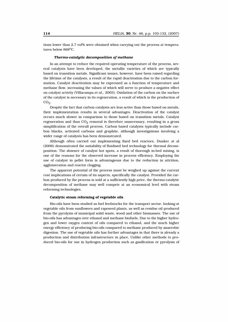
In the UFP technology, three circulating fluidized beds are fed coal, steam andair to produce separate streams of (1) high-purity hydrogen that be utilized in fuelcells or turbines, (2) sequestration-ready CO2, and (3) high temperature and pres-sure vitiated air to produce electricity in gas turbine (Rizeq et al., 2003). The UFPtechnology makes use of three circulating fluidized bed reactor containing a CO2Absorbing Material (CAM) and Oxygen Transfer Material (OTM), just as the originalunmixed steam reforming process. The CAM is a sorbent that adsorbs CO2 and theOTM is a metal oxide that oxidises to form OTM-O. Three reactors are connectedtogether and a mixture of the bed material and coal ash is present in each reactor.
Figure 3 shows how the UFP operates with constant coal and steam feeds toproduce a H2-rich gas, a sequestration ready CO2 flow and a hot high pressureexhaust gas (N2-rich O2-depleted) which can be used in a gas turbine for addedoverall process energy efficiency.
Unmixed steam reforming of methane and sunflower oil work at Leeds University
Figure 4 depicts the experimental set-up for the USR bench scale rig at LeedsUniversity. A close up diagram of the USR reactor can be seen in Figure 5.
Reactant gases were controlled by three mass flow controllers for nitrogen,methane and air followed by three solenoid valves operated in sequence. The liquidfeeds of water and vegetable oil were regulated by two actuated valves switchingbetween the AF and FF steps. All valves were centrally controlled by a sequence gen-
Figure 3: Schematic of operation of the UFP (from Rizeq et al., 2003)
122 HELIA, 30, Nr. 46, p.p. 103-132, (2007)
erator. When the unit was not operating (not cycling), a third valve allowed flushingof the assembly with nitrogen.
The product gases were cooled using a water-cooled condenser before enteringa water trap (ice bath), followed by a chemical water trap (silica gel). The dry gase-ous products CO/CO2, CH4, H2 and O2 were fed through a series of on-line analys-ers from ABB and data-logged. The gas reaching the analysers was dry and at roomtemperature. For safety reasons, the entire gas product stream was diluted with airand N2 and disposed of by flowing it over resistively-heated platinum gauze withinan enclosure, where its combustible components were removed by catalytic com-bustion. Two relief valves were situated before and after the reactor to maintain thereactor pressure below 2 bar. Pressure and temperature readings were measured atvarious points in the rig as described in Figures 4-5. The reactor had an internalvolume of 80 cm3. It contained a combination of an OTM chosen from a previousmicroreactor study in (Ross et al., 2004) and in the final tests, a mixture of theOTM and a natural dolomite, in ground pellets form of approximately 1-2 mm size,preceded and succeeded by two plugs of alumina particles. We report here experi-ments where either 80 or 40 g of OTM were used. The reactor was heated externallyby a coiled 1 kW tubing heater which was actuated in an ‘on-off’ control feedbackloop using the middle-reactor thermocouple as the measuring element, and a refer-ence temperature that could be set in the range 600-800°C. The heating elementwas first clad with K wool then surrounded by an alumina casing itself enclosed in astainless steel casing.
Figure 4: Diagram of bench scale USR set up at Leeds University
HELIA, 30, Nr. 46, p.p. 103-132, (2007) 123
Methane work
To understand how the process worked with vegetable oil, a model fuel had tobe investigated first with the unmixed steam reforming process. With its simplecomposition C1H4, and the relatively few carbon and hydrogen containing productsof conversion via thermal decomposition and steam reforming (C, CO, CO2), meth-ane was the ideal candidate. It presented the added advantage that conventional cat-alytic steam reforming of methane was well known and therefore provided anexcellent basis for comparison to the USR process and the verification of its advan-tages and drawbacks.
Figure 5: Close up diagram of USR reformer reactor at Leeds University
Figures 6a-b: Methane and steam percent conversions during FF (fuel/steam flow step) on 40 g of OTM ‘A’ (Ni content of 27.5 wt% on alumina) for a reactor temperature of 800°C, at a steam/methane molar ratio of 1.8 using a step duration of 600 s (a) methane flow of 152 sccm (1.13×10⁻⁴ mol of C/s) and (b) 400 sccm (3×10⁻⁴ mol of C/s). These runs were without CO2 sorbent. (Dupont et al., 2006)
124 HELIA, 30, Nr. 46, p.p. 103-132, (2007)
The graphs of Figures 6a and 6b indicate that with the USR process, the steam,with a conversion of 42-48%, is as valuable a source of hydrogen as the fuel (98%).This is unlike the conventional catalytic steam reforming process which operateswith a steam to carbon ratio of at least 3.5, i.e. with a large excess of water whichcarries purification, vapourisation and recycling costs. In many parts of the worldthe availability of clean water might be an issue, and being able to operate at asteam to carbon ratio of 1.8 as in the USR process could be very advantageous.
Figure 6b, which represents an operation with a larger fuel/steam inflow (400sccm or cm3/min at STP) than Figure 6a (152 sccm), indicates that choosing theright flow for the reactor size has large consequences on the time at which steamreforming initiates. Given that the FF duration is short, of the order of 6-10 min-utes, this has a crucial role in the overall hydrogen production efficiency, when inte-grated over the whole fuel-steam step duration.
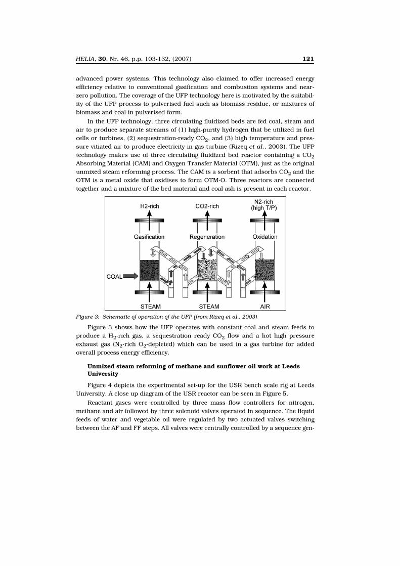
The effect of operating with dolomite as the CO2 sorbent in the reactor is illus-trated in Figure 7. At a reactor temperature of 600°C, the purity of the reformatereaches above 90% in hydrogen. The same experiment with a reactor temperatureof 650°C lowers the reformate H2 purity to 75%. When a reformate purity of 75-90%is achieved, downstream water shift reactors are not necessary, which reduces thecapital and operating costs of the process.
USR operation with sunflower oil
Table 6 indicates that the dry H2 content achieved in the reformate in theabsence of CO2 sorbent is, with a value of 67.2% very similar to that obtained previ-ously by Marquevich et al. (2000). However in the Leeds runs, the conversion of
Figure 7: H2 content in reformate (on a dry basis) when using a reactor set temperature of 600°C (dashed line) and 650°C (solid line) during FF step, over 64 g of OTM ‘A’ and 21 g of dolomite homogeneously mixed. The flow of methane was main-tained at 200 sccm, with a steam to carbon ratio of 4.
HELIA, 30, Nr. 46, p.p. 103-132, (2007) 125
steam (32%), thanks to an operation with a steam to carbon ratio of 1.8, contrib-utes greatly to the overall H2 production efficiency. A drawback is found in this run:for 25% of the initial fuel/steam step duration, steam reforming is inactive and indi-cates optimisation of the flows for this reactor load could achieve an earlier activa-tion of the steam reforming reaction, as carried out for the methane experiments.
Further optimisation could be achieved in converting the methane by-product(15% of carbon products) to hydrogen and CO2, and this can be done by using ahigher temperature in the reactor. With regards to other carbon products of thethermal cracking of the sunflower oil (mainly C2H4 ethylene), it is expected that atthe temperature of 700°C, these would have undergone either catalytic cracking tocarbon and hydrogen, or steam reforming as found in early experiments at Leeds(Powell, 2003) and in the work of Marcquevich et al. (2000).
The large carbon deposition resulting from the high carbon selectivity wouldeventually poison the catalyst, but the advantage of the USR process is that the fuel/steam steps are of short durations (6-10 min) and followed by the air feed step, dur-ing which the carbon burns and the bed material regenerates and heats up.
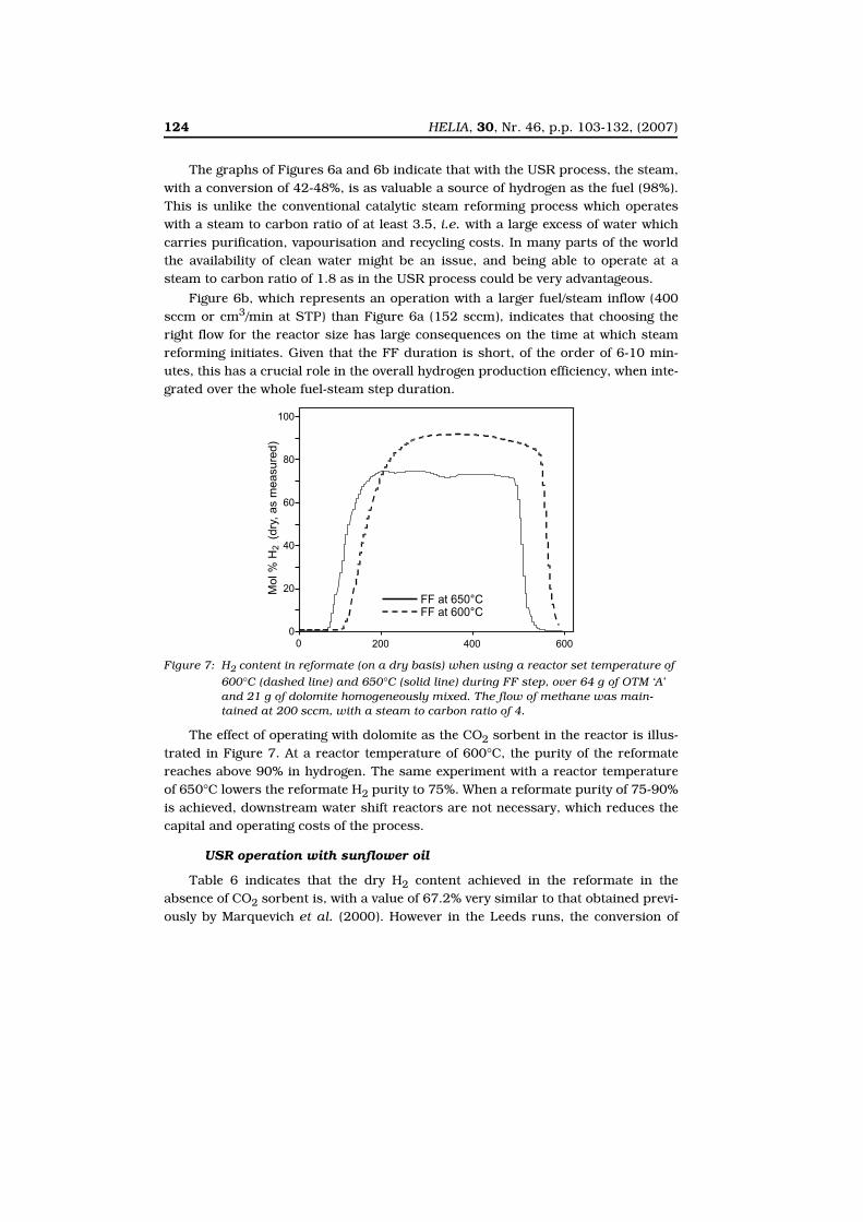
Table 6: Results obtained for OTM ‘A’ during the bench scale USR Leeds University tests usingsunflower oil with N2-diluted steam/C ratio of 1.8 in the absence of CO2-sorbent overa bed of 80 g of OTM at 700°C. Average values are reported for the period ofestablished steam reforming. The duration of the FF step was 400 s. Sunflower oilmolar composition: C18H34.4O2.1. (Dupont et al., 2006)
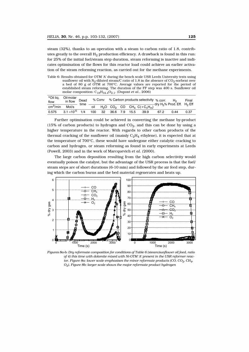
Figures 8a-b: Dry reformate composition for conditions of Table 6 (steam/sunflower oil feed, ratio of 4) this time with dolomite mixed with Ni-OTM ‘A’ present in the USR reformer reac-tor. Figure 8a: lower scale emphasises the minor reformate products (CO, CO2, CH4, O2), Figure 8b: larger scale shows the major reformate product hydrogen
126 HELIA, 30, Nr. 46, p.p. 103-132, (2007)
The results shown in Figures 8a-b are from early tests at Leeds University andindicate that it is possible to obtain a reformate with more than 90% dry H2 contentwhen using sunflower oil to fuel the USR process, when using dolomite as the CO2sorbent and the Ni-OTM catalyst with a medium-high Nickel content (‘A’ contains27.5 wt% Ni impregnated on an Alumina support). We found that such an excellentoperation is difficult to sustain over repeated cycles when operating with a single settemperature, and attribute the lower dry H2 content of subsequent cycles (shown inFigure 9) to the lack of regeneration of the dolomite at the set reactor temperatureof 600°C during the air flow. This would indicate that during the air flow, this tem-perature is insufficient to decompose the carbonate, and as a result the CO2 can nolonger adsorb with a resulting increase in reformate CO2 content in the followingfuel-steam step. One can see from the air feed steps dry gas compositions that someCO2 evolves from the reactor but that this is likely to be due to carbon combustionrather than carbonate decomposition given the large CO2 concentrations found dur-ing the subsequent fuel-steam feed step. As an optimisation step, it would be there-fore be useful to increase the reactor set temperature to 800°C during the air feedsteps, to ensure regeneration of the CO2 sorbent.
It is also interesting to note that the second and third cycles produce a similarreformate composition to that of Marquevich et al. (2003), in that hardly any CO isfound in the reformate. In contrast, some methane is found, indicating that theprocess could be further optimised by achieving its decomposition or steam reform-ing.
Future work at Leeds
Significant work is on-going at Leeds to find the optimum conditions for themechanism of the Ni-OTM reduction. It has been established that the steam reform-ing reaction is delayed until the Ni-OTM catalyst has been reduced to a certain level
Figure 9: Dry reformate gas composition for three initial cycles sunflower oil+steam feed/ air feed in conditions of Figure 8ab. In order of decreasing content: H2>>CO2>CH4>>CO.
HELIA, 30, Nr. 46, p.p. 103-132, (2007) 127
(minimum of ca. 15%). Any hydrogen produced up to then is via the less efficientthermal decomposition reaction of the fuel, which does not use the added value ofthe water-hydrogen content. It is therefore crucial to establish steam reforming assoon as possible given that the Ni material operates equally as an oxygen transfermaterial and as a steam reforming catalyst. The latter has implications with respectto the sensitivity of the material to poisons and might compromise the claims of fuelflexibility as a result. Another strand of the project is dedicated to the optimisationof the autothermal behaviour, so far very little explored, using methane and sun-flower oil as the fuel. In continuation to this, more challenging fuels will be investi-gated, such as waste cooking oil, pyrolysis oils from pine wood residue, and alsomyscanthus as representatives of high lignin and low lignin biomass sourcesrespectively, producing highly oxygenated oils. Industrial waste oil and pyrolysiswaste tyre oils will also be studied, to represent low oxygen high sulphur contentoils. It is also intended to devote another section of the study to the development ofappropriate CO2 sorbents for these oils.
Implications for distributed electrical power generation using a pilot plant sunflower fuelled USR
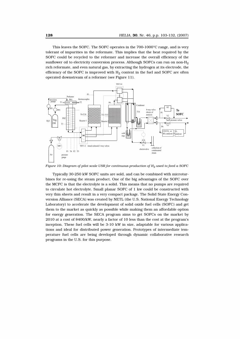
The sunflower oil-fuelled USR process at pilot scale, with the aims of continu-ously powering a fuel cell for electricity generation would have to rely on two USRreactors operating out of phase: while one is under fuel-steam feed, the other isunder air feed and vice versa, ensuring an uninterrupted supply of hydrogen-richreformate (see Figure 10).
There are various types of fuel cells, but those which require very pure hydro-gen as their fuel (polymer electrolyte membrane fuel cells, alkaline fuel cells) needto be discarded since this would necessitate expensive purification steps down-stream of the USR reformers. This leaves the ‘molten carbonate’, ‘phosphoric acid’and ‘solid oxide’ fuel cells (MCFC, PAFC, SOFC), their names referring to the type ofelectrolyte they rely on. The first kind (MCFC) tends to be used at very large scale (2to 100 MW) due to the complexity of operating with a liquid electrolyte which needscontinuous CO2 injection. Their temperature of operation (650°C) is however wellsuited to its coupling with a reformer, allowing heat integration and co-generation(steam and electricity generation). Phosphoric acid fuel cells rely on a Pt catalyst atthe electrodes to speed up the decomposition of hydrogen and the formation ofwater, but because they operate between 150 and 200°C, they have a tolerance toCO content up to 1.5%. They are used for stationary power generation. For instancea 250-kilowatt phosphoric acid fuel cell powers a police station and is used torecharge a police electric vehicle in New York's Central Park. Whereas 1.5% CO con-tent can be achieved by a well tuned sunflower oil fuelled USR process, fluctuationsdue to autothermal operation could exceed this value occasionally, leading to grad-ual poisoning of the PAFC electrodes.
128 HELIA, 30, Nr. 46, p.p. 103-132, (2007)
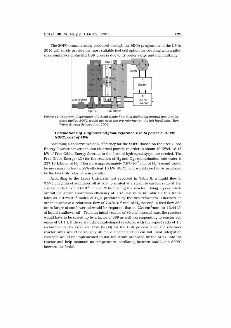
This leaves the SOFC. The SOFC operates in the 700-1000°C range, and is verytolerant of impurities in the reformate. This implies that the heat required by theSOFC could be recycled to the reformer and increase the overall efficiency of thesunflower oil to electricity conversion process. Although SOFCs can run on non-H2rich reformate, and even natural gas, by extracting the hydrogen at its electrode, theefficiency of the SOFC is improved with H2 content in the fuel and SOFC are oftenoperated downstream of a reformer (see Figure 11).
Typically 30-250 kW SOFC units are sold, and can be combined with microtur-bines for re-using the steam product. One of the big advantages of the SOFC overthe MCFC is that the electrolyte is a solid. This means that no pumps are requiredto circulate hot electrolyte. Small planar SOFC of 1 kw could be constructed withvery thin sheets and result in a very compact package. The Solid State Energy Con-version Alliance (SECA) was created by NETL (the U.S. National Energy TechnologyLaboratory) to accelerate the development of solid oxide fuel cells (SOFC) and getthem to the market as quickly as possible while making them an affordable optionfor energy generation. The SECA program aims to get SOFCs on the market by2010 at a cost of $400/kW, nearly a factor of 10 less than the cost at the program’sinception. These fuel cells will be 3-10 kW in size, adaptable for various applica-tions and ideal for distributed power generation. Prototypes of intermediate tem-perature fuel cells are being developed through dynamic collaborative researchprograms in the U.S. for this purpose.
Figure 10: Diagram of pilot scale USR for continuous production of H2 used to feed a SOFC
HELIA, 30, Nr. 46, p.p. 103-132, (2007) 129
The SOFCs commercially produced through the SECA programme in the US by2010 will surely provide the most suitable fuel cell option for coupling with a pilot-scale sunflower oil-fuelled USR process due to its power range and fuel flexibility.
Calculations of sunflower oil flow, reformer size to power a 10 kW SOFC, cost of kWh
Assuming a conservative 55% efficiency for the SOFC (based on the Free GibbsEnergy flowrate conversion into electrical power), in order to obtain 10 KWel, 18.18kW of Free Gibbs Energy flowrate in the form of hydrogen/oxygen are needed. TheFree Gibbs Energy (∆G) for the reaction of H2 and O2 recombination into water is237.13 kJ/mol of H2. Therefore approximately 7.67×10⁻² mol of H2 /second wouldbe necessary to feed a 55% efficient 10 kW SOFC, and would need to be producedby the two USR reformers in parallel.
According to the Leeds University test reported in Table 6, a liquid flow of0.575 cm3/min of sunflower oil at STP, operated at a steam to carbon ratio of 1.8,corresponded to 5.33×10⁻⁴ mol of 2H/s fuelling the reactor. Using a pessimisticoverall fuel-steam conversion efficiency of 0.37 (last value in Table 6), this trans-lates as 1.972×10⁻⁴ moles of H2/s produced by the two reformers. Therefore inorder to achieve a reformate flow of 7.67×10⁻² mol of H2 /second, a feed-flow 389times larger of sunflower oil would be required, that is, 224 cm3/min (or 13.44 l/hof liquid sunflower oil). From an initial reactor of 80 cm3 internal size, the reactorswould have to be scaled up by a factor of 389 as well, corresponding to reactor vol-umes of 31.1 l. If these are cylindrical-shaped reactors, with the aspect ratio of 1.5recommended by Lyon and Cole (2000) for the USR process, then the reformerreactor sizes would be roughly 40 cm diameter and 60 cm tall. Heat integrationconcepts would be implemented to use the steam produced by the SOFC into thereactor and help maintain its temperature (oscillating between 600°C and 800°Cbetween the feeds).
Figure 11: Diagram of operation of a Solid Oxide Fuel Cell fuelled by natural gas. A refor-mate fuelled SOFC would not need the pre-reformer on the left hand side. (Ben Wiens Energy Science Inc., 2006)
130 HELIA, 30, Nr. 46, p.p. 103-132, (2007)
At the time of writing this paper (Sept. 2006), with a wholesale price of 0.459Euros/l of sunflower oil, the cost of sunflower oil consumption to run the 10 kWelUSR-SOFC process would be 6.2 Euros/kWh based on fuel consumption only. Thiscompares favourably to the average European price of 7.69 Euros per kWh.
ACKNOWLEDGEMENTS
This paper is heavily indebted to my MSc students Marc Knowles,Jonathan Powell, Mathieu Lucquiaud, Bo (Peter) Jiang and LawrenceAdediran, my Ph.D. students Elisabeth (Liz) Knight, Ian Hanley andGavin Rickett, and Dr. Andy B. Ross. Many thanks to Dr. Martyn V.Twigg at Johnson Matthey Catalysts, Royston, UK. The work at Leedshas been funded by EPSRC grant GR/R50677 from 2002-2005, currentand future work is funded by an EPSRC-Johnson Matthey CASEaward (E. Knight), and EPSRC grant EP/D078199/1 until December2009.
REFERENCES
Ben Wiens Energy Science Inc., 2006. Look at: http://www.benwiens.com/energy4.html#energy1.8.
Dunker, M., Kumar, S. and Mulawa, P.A., 2006. International Journal of Hydrogen Energy, 31:473-484.
Dupont, V., Ross, A.B., Hanley, I., Twigg, M.V., 2006. Accepted for publication in InternationalJournal of Hydrogen Energy.
Ersoz, A., Olgun, H., Ozdogan, S., 2006. Journal of Power sources 154: 67-73.Ewan, B.C.R. and Allen, R.W.K., 2005. International Journal of Hydrogen Energy 30: 809-819.Ishida, M., Zheng, D., Ahehata, T., 1987. Energy 12(2): 147-154.Kumar, R.V., Cole, J. A., Lyon, R.K., 1999. Preprints of Symposia, J. Am. Chem. Soc. 44(4).Lyon, R.K., Cole, J.A., 2000. Combustion and Flame 121: 249-261.Maack, M.H. and Skulason, J.B., 2006. Journal of Cleaner Production 14: 52-64.Marquevich, M., Sonnemann, G.W., Castells, F., Montane, D., 2002. Green Chemistry 4(5): 414-
423.Marquevich, M., Coll, R., Montane, D., 2000. Industrial Engineering Chemistry Research 39:
2140-2147.Marquevich, M., Farriol, X., Medina, F. and Montane, D., 2003. Catalysis Letters 85(1-2): 41-48.Mazza, P., Hammerschlag, R., 2004. Institute for Lifecycle Environment assessment.Ni, M., Leung, D.Y.C., Leung, M.K.H. and Sumathy, K., 2006. Fuel Processing Technology 87:
461-472.Palm, T., Buch, C.B., Sauar, K.E., 1999. Green Heat and Power, Bellona Foundation, Look at:
(http://www.bellona.no/imaker?id=11191%E2%8A%82=1)Powell, J., 2003. MSc thesis, MSc Environmental Pollution Control, The University of Leeds.Rizeq, G., West, J., Frydman, A., Subia, R., Zamansky, V., Loreth, H., Stonawski, L., Wiltowski,
Ross, A.B., Dupont, V., Hanley, I., Jones, J.M., and Twigg, M.V., 2004. Presented at: Sciencein Thermal and Chemical Biomass Conversion, 30th Aug-2nd Sept. Victoria, Canada.
Sherif, S.A., Barbir, F. and Veziroglu, T.N., 2005. The Electricity Journal 18: 62-76.Son, S.R. and Kim, S.D., 2006. Industrial Engineering Chemistry Research 45: 2689-2696.Tseng, P., Lee, J. and Friley, P., 2005. Energy 30: 2703-2720.Villacampa, J.I., Royo, C., Romeo, E., Montoya, J.A., Del Angel, P. and Monzón, A., 2003.
Applied Catalysis A: General 252: 363-383.
HELIA, 30, Nr. 46, p.p. 103-132, (2007) 131
OXIDACIÓN CATALÍTICA DEL ACEITE DE GIRASOL EN LA PRODUCCIÓN DEL GAS HIDRÓGENO
RESUMEN
En el trabajo, en breve se consideran los métodos que se utilizan en laproducción de hidrógeno contemporánea para las necesidades de la industriade procesamiento del petróleo, tanto como de las futuras tecnologías que sedesarrollan actualmente, como preparación de la economía global, basada enla utilización del gas hidrógeno. Luego se da el cuadro de las ventajas de la bio-masa y de los biocombustibles líquidos, incluyendo los aceites de origen vege-tal, como fuente de combustible en la producción sostenible del hidrógeno enforma de gas. La mayor parte del trabajo se dedica a los procesos termo-químicos en la producción del hidrógeno, que son apropiados para la transfor-mación de aceites vegetales en el hidrógeno gaseoso. Especialmente se estáconsiderando el trabajo que se ha hecho hasta el momento, en cuanto a la oxi-dación catalítica de carburo de hidrógeno mediante el vapor de agua, tantocomo las ventajas y desventajas, en relación con los métodos convencionales.En continuación, está descrito el principio de un proceso de transformación debiogases totalmente nuevo, mediante el vapor de agua, llamado ‘unmixedsteam reforming’ (USR), que es ajustable para todos los tipos de biogases,insensible a los problemas de índole termal, y por ello pertinente para laobtención de todos los tipos de biocombustibles gaseosos y líquidos no con-vencionales. Luego se presentan y discutan, sobre la base del trabajo realizadoen la Universidad de Leeds, los resultados preliminares de investigación de laaplicación del proceso USR en la obtención de biocombustible del aceite degirasol. Como conclusión, se expone la descripción del futuro trabajo planifi-cado en este campo de investigaciones.
REFORMAGE À LA VAPEUR DE L’HUILE DE TOURNESOL DANS LA PRODUCTION DE GAZ HYDROGÈNE
RÉSUMÉ
Cet article résume brièvement les méthodes utilisées dans la productionmoderne d’hydrogène pour les besoins de l’industrie de raffinement du pétroleainsi que les technologies qui se développent actuellement dans le but d’élab-orer une économie mondiale basée sur l’utilisation du gaz hydrogène. Puis, ilprésente les avantages de la biomasse et des carburants liquides, incluant leshuiles végétales en tant que sources de carburants dans la production durablede gaz hydrogène. La plus grande partie de l’article traite des procédés thermo-chimiques favorables à la conversion d’huile végétale en gaz hydrogène dans laproduction d’hydrogène. Il traite particulièrement du travail fait jusqu’à main-tenant sur le reformage catalytique des huiles végétales et des avantages etinconvénients du reformage à la vapeur traditionnel. Puis il décrit le principed’un tout nouveau procédé de transformation de biogaz à l’aide de la vapeurd’eau appelé “unmixed steam reforming“ (USR) qui est adaptable à toutes lessortes de biogaz, insensible aux problèmes de nature thermique et ainsipropice à l’obtention de toutes les sortes de biocarburants non traditionnelssous forme de liquide ou de gaz. Puis, d’après le travail fait à l’université deLeeds, les résultats préliminaires des tests du procédé USR incluant le car-burant à l’huile de tournesol sont présentés et discutés. En conclusion, ildonne une description du travail projeté dans ce domaine de recherche.