Studia Geotechnica et Mechanica, Vol. XXXV, No. 2, 2013 DOI: 10.2478/sgem-2013-0023 ANALYTICAL VERIFICATION OF OUTLET DEVICES CAPACITY OF LUBACHÓW STORAGE RESERVOIR ON THE BYSTRZYCA RIVER JERZY MACHAJSKI Institute of Geotechnics and Hydrotechnics, Wrocław University of Technology, Wybrzeże Wyspiańskiego 27, 30-370 Wrocław, Poland. DOROTA OLEARCZYK Institute of Environmental Engineering, Wrocław University of Environmental Life Sciences, Poland. Abstract: The Lubachów storage reservoir was built in the 1920’s. It is equipped with a relatively complex outlet installation, operating in variable hydraulic regime. The discharge deviations curves elaborated by German engineers for individual devices, after verification turned out to be burdened with a comparatively big error. This concerns especially the front spillway as well as intermediate outlets, and to a smaller degree the bottom outlets. The authors made a detailed analytical verifica- tion of the outlet installations and found great deviations from the currently valid discharge curves for these devices. Based on the analysis of conditions of computational discharges passage through the reservoir, they proved a high potential threat of water flow over the dam crest. 1. INTRODUCTION The Lubachów storage reservoir on the Bystrzyca River was designed for the needs of flood protection of downstream areas as well as electric energy production by a small hydro power plant located downstream. In the 1970’s to previous tasks a water uptake for industry was added, which in the 1990’s was changed to serve municipal aims. Be- cause the reservoir storage is small and water needs are great, the flood protection func- tion was delimited by splitting an insignificant flood control storage in the reservoir. This brought about certain fears if with the moment of flood wave inflow, for example design wave, into reservoir there is a real possibility of its failure-free transformation to tail- water, without any damage to the object itself and to downstream area. In the first phase of this study the authors carried out an analytical verification of capacity of existing outlet devices, because of more and more frequent opinions about their possible over-dimensioning by German engineers. In the paper, the results of calculations are presented. 2. OBJECT DESCRIPTION The Lubachów storage reservoir [1] was formed as a result of river partitioning at 80+143 km of its watercourse by stone dam. Reservoir capacity at water level corre-
Transcript
Studia Geotechnica et Mechanica, Vol. XXXV, No. 2, 2013DOI: 10.2478/sgem-2013-0023
ANALYTICAL VERIFICATION OF OUTLET DEVICES CAPACITYOF LUBACHÓW STORAGE RESERVOIR
ON THE BYSTRZYCA RIVER
JERZY MACHAJSKI
Institute of Geotechnics and Hydrotechnics, Wrocław University of Technology,Wybrzeże Wyspiańskiego 27, 30-370 Wrocław, Poland.
DOROTA OLEARCZYK
Institute of Environmental Engineering, Wrocław University of Environmental Life Sciences, Poland.
Abstract: The Lubachów storage reservoir was built in the 1920’s. It is equipped with a relativelycomplex outlet installation, operating in variable hydraulic regime. The discharge deviations curveselaborated by German engineers for individual devices, after verification turned out to be burdenedwith a comparatively big error. This concerns especially the front spillway as well as intermediateoutlets, and to a smaller degree the bottom outlets. The authors made a detailed analytical verifica-tion of the outlet installations and found great deviations from the currently valid discharge curvesfor these devices. Based on the analysis of conditions of computational discharges passage throughthe reservoir, they proved a high potential threat of water flow over the dam crest.
1. INTRODUCTION
The Lubachów storage reservoir on the Bystrzyca River was designed for the needsof flood protection of downstream areas as well as electric energy production by a smallhydro power plant located downstream. In the 1970’s to previous tasks a water uptakefor industry was added, which in the 1990’s was changed to serve municipal aims. Be-cause the reservoir storage is small and water needs are great, the flood protection func-tion was delimited by splitting an insignificant flood control storage in the reservoir. Thisbrought about certain fears if with the moment of flood wave inflow, for example designwave, into reservoir there is a real possibility of its failure-free transformation to tail-water, without any damage to the object itself and to downstream area.
In the first phase of this study the authors carried out an analytical verification ofcapacity of existing outlet devices, because of more and more frequent opinions abouttheir possible over-dimensioning by German engineers. In the paper, the results ofcalculations are presented.
2. OBJECT DESCRIPTION
The Lubachów storage reservoir [1] was formed as a result of river partitioning at80+143 km of its watercourse by stone dam. Reservoir capacity at water level corre-
J. MACHAJSKI, D. OLEARCZYK50
sponding to the dam crest elevation of 352.0 m a.s.l. equals Vzb = 9.1 mln m3, withreservoir area of about 51 ha and resultant backwater length of about 3 km.
Fig. 1. Functional plan of the Lubachów storage reservoir dam
Analytical verification of outlet devices capacity... 51
The dam body was built with natural local stone on cement mortar as monolithicstructure without expansion joints. It was founded on concrete layer, levelling theground of biotite gneiss. The average dam width at the base equals 29 m. The radius ofthe dam circular arch at the crest level is equal to 250 m (Fig. 1). Upstream dam bodyslope up to elevation of 343.50 m a.s.l. is covered by cement mortar of 6.50 cm inthickness, above this level it is covered by protective stone pointing by cement mortar.Downstream dam body slope is faced with local stone pointing by cement mortar. Thedam crest width is equal to 3.50 m and its elevation is 352.0 m a.s.l. The dam length atcrest equals 230.50 m, and at a base about 80 m, a minimum foundation elevation is308.0 m a.s.l. The dam crest is topped with service road, with pavement made ofgranite cubes on concrete layer.
The powerhouse is located about 1.0 km downstream from the dam. It is foundedon rock, which is a support for dam body. In a turbine room there are three turbine setsinstalled, conduits that supply water to the turbines are laid perpendicularly to longitu-dinal wall of the building and are a branching of the main supply conduit of 1800 mmin diameter. The penstock fulfils a double function; it delivers water from the reservoirto the hydro power plant and to the intermediate pumping station for water supplypurposes.
3. RESERVOIR OUTLET DEVICES
Outlet devices of Lubachów reservoir consist of front spillway in the form of 10orifices, 4 intermediate outlets, 2 conduits of bottom channel, water intake for smallhydro power station and potable water intake, stilling basin joining a trained by ero-sion-control step the Bystrzyca River bed [1].
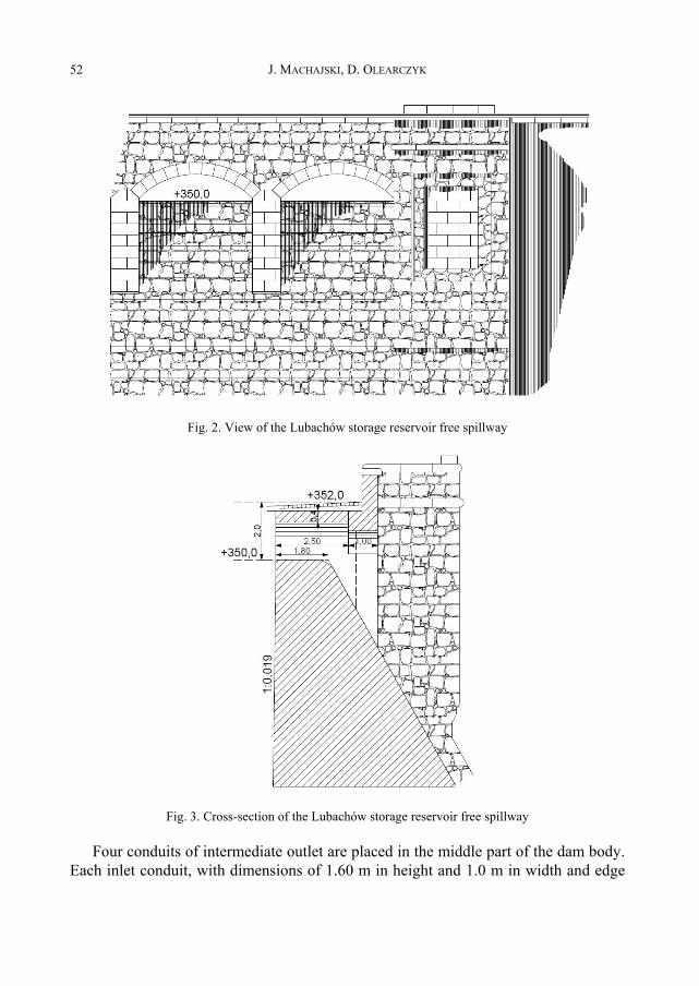
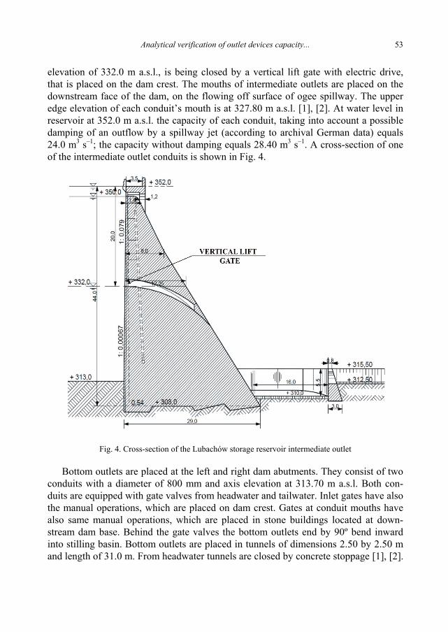
Spillway consists of 10 orifices located in the central part of the dam. The shapeof opening cross-section is close to a semicircle with the weir crest elevation at350.0 m a.s.l. (Fig. 2). The width of each opening in its lower part equals 3.60 m, andmaximum height is 1.30 m. Because of spillway cross-section shape, height positionof upper and bottom edge, and also irregular changeability of its cross-section area asa function of height from weir crest (bottom edge) the spillway works in variable hy-draulic regime. When a water level in reservoir reaches an elevation of 351.40 m a.s.l.,the upper edge of spillway becomes submerged and the character of flow changes fromoverflow to outflow from big not submerged orifice [1], [2].The capacity of overflowspillway (according to archival German data) was estimated to be about 200 m3 s–1 forwater level in reservoir corresponding to dam crest elevation at 352,0 m a.s.l.A view of the front spillway is shown in Fig. 2 and a spillway cross-section is shownin Fig. 3.
J. MACHAJSKI, D. OLEARCZYK52
Fig. 2. View of the Lubachów storage reservoir free spillway
Fig. 3. Cross-section of the Lubachów storage reservoir free spillway
Four conduits of intermediate outlet are placed in the middle part of the dam body.Each inlet conduit, with dimensions of 1.60 m in height and 1.0 m in width and edge
Analytical verification of outlet devices capacity... 53
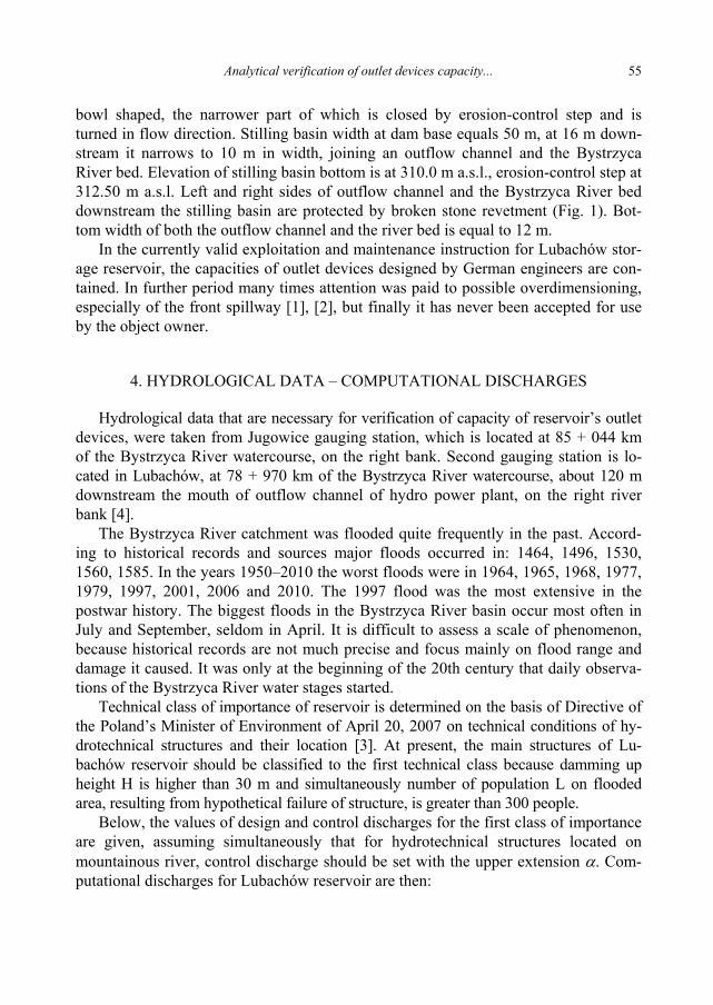
elevation of 332.0 m a.s.l., is being closed by a vertical lift gate with electric drive,that is placed on the dam crest. The mouths of intermediate outlets are placed on thedownstream face of the dam, on the flowing off surface of ogee spillway. The upperedge elevation of each conduit’s mouth is at 327.80 m a.s.l. [1], [2]. At water level inreservoir at 352.0 m a.s.l. the capacity of each conduit, taking into account a possibledamping of an outflow by a spillway jet (according to archival German data) equals24.0 m3 s–1; the capacity without damping equals 28.40 m3 s–1. A cross-section of oneof the intermediate outlet conduits is shown in Fig. 4.
Fig. 4. Cross-section of the Lubachów storage reservoir intermediate outlet
Bottom outlets are placed at the left and right dam abutments. They consist of twoconduits with a diameter of 800 mm and axis elevation at 313.70 m a.s.l. Both con-duits are equipped with gate valves from headwater and tailwater. Inlet gates have alsothe manual operations, which are placed on dam crest. Gates at conduit mouths havealso same manual operations, which are placed in stone buildings located at down-stream dam base. Behind the gate valves the bottom outlets end by 90º bend inwardinto stilling basin. Bottom outlets are placed in tunnels of dimensions 2.50 by 2.50 mand length of 31.0 m. From headwater tunnels are closed by concrete stoppage [1], [2].
J. MACHAJSKI, D. OLEARCZYK54
The capacity of each conduit (according to archival German data) was estimatedat 11.50 m3 s–1 for water level in reservoir at 352.0 m a.s.l. Cross-section of the one ofthe bottom outlets is shown in Fig. 5.
Fig. 5. Cross-section of the Lubachów storage reservoir bottom outlet
Water is delivered to three turbine sets by one penstock with a diameter of 1800 mm,whose axis elevation from the side of an inlet is at 323.00 m a.s.l. The conduit of totallength equal 968.50 m is made of steel plate with riveted joints. The penstock isequipped with inlet and outflow gates. Manual operation from headwater is placed ondam crest, and manual operation from tailwater is located in special shaft at tailwaterdam base. In the hydro power plant three turbine sets are installed, equipped withFrancis turbines, placed in a spiral cast-iron casing with generators on a common shaftand nominal head is equal to 40.0 m. Total installed electric power of turbine sets isequal to 1.150 MW, and their total capacity is estimated at 4.60 m3 s–1 for water levelin reservoir at 346.0 m a.s.l.
The stilling basin is located downstream of the outflow face from spillway and in-termediate outlets, also mouths of bottom channel are placed in it. Stilling basin is
Analytical verification of outlet devices capacity... 55
bowl shaped, the narrower part of which is closed by erosion-control step and isturned in flow direction. Stilling basin width at dam base equals 50 m, at 16 m down-stream it narrows to 10 m in width, joining an outflow channel and the BystrzycaRiver bed. Elevation of stilling basin bottom is at 310.0 m a.s.l., erosion-control step at312.50 m a.s.l. Left and right sides of outflow channel and the Bystrzyca River beddownstream the stilling basin are protected by broken stone revetment (Fig. 1). Bot-tom width of both the outflow channel and the river bed is equal to 12 m.
In the currently valid exploitation and maintenance instruction for Lubachów stor-age reservoir, the capacities of outlet devices designed by German engineers are con-tained. In further period many times attention was paid to possible overdimensioning,especially of the front spillway [1], [2], but finally it has never been accepted for useby the object owner.
4. HYDROLOGICAL DATA – COMPUTATIONAL DISCHARGES
Hydrological data that are necessary for verification of capacity of reservoir’s outletdevices, were taken from Jugowice gauging station, which is located at 85 + 044 kmof the Bystrzyca River watercourse, on the right bank. Second gauging station is lo-cated in Lubachów, at 78 + 970 km of the Bystrzyca River watercourse, about 120 mdownstream the mouth of outflow channel of hydro power plant, on the right riverbank [4].
The Bystrzyca River catchment was flooded quite frequently in the past. Accord-ing to historical records and sources major floods occurred in: 1464, 1496, 1530,1560, 1585. In the years 1950–2010 the worst floods were in 1964, 1965, 1968, 1977,1979, 1997, 2001, 2006 and 2010. The 1997 flood was the most extensive in thepostwar history. The biggest floods in the Bystrzyca River basin occur most often inJuly and September, seldom in April. It is difficult to assess a scale of phenomenon,because historical records are not much precise and focus mainly on flood range anddamage it caused. It was only at the beginning of the 20th century that daily observa-tions of the Bystrzyca River water stages started.
Technical class of importance of reservoir is determined on the basis of Directive ofthe Poland’s Minister of Environment of April 20, 2007 on technical conditions of hy-drotechnical structures and their location [3]. At present, the main structures of Lu-bachów reservoir should be classified to the first technical class because damming upheight H is higher than 30 m and simultaneously number of population L on floodedarea, resulting from hypothetical failure of structure, is greater than 300 people.
Below, the values of design and control discharges for the first class of importanceare given, assuming simultaneously that for hydrotechnical structures located onmountainous river, control discharge should be set with the upper extension α. Com-putational discharges for Lubachów reservoir are then:
J. MACHAJSKI, D. OLEARCZYK56
Qm = Q0.5% = 310 m3 s–1,
Qk = Q0.1% = 567 m3 s–1,α
%1.0QQak = = 801 m3 s–1.
5. THEORETICAL HYDRAULICS BASIS OF OUTLET INSTALLATION
In analytical calculations of capacity of outlet devices, first the operating condi-tions of a given device should be established, which are connected with mutual waterlevel elevation and spillway crest elevation, also a hydraulic scheme determininga flow character – orifice, spillway, outlet submergence or lack of submergence. Be-cause a capacity is a function of device parameters and flow velocity, that is why anacceptance of proper hydraulic scheme have the most significant impact on final de-termination the capacity of given device. Simultaneously, because some of devices areequipped in movable gates, hence, again a flow character should be set – over or undera gate and principles of its operation [5]–[9].
The above approach was applied for determination of capacity of Lubachów reser-voir’s outlet installations.
5.1. BOTTOM OUTLETS
The bottom outlets of Lubachów reservoir work under relatively favourable hy-draulic conditions, an inlet from headwater is entirely submerged, mouth from tailwa-ter is free [5], [7]–[9]. However, it should be mentioned that mouths of bottom outletswork as free till moment when front spillway starts its working, since even intermedi-ate outlets work entirely, a river outflow is not significant to submerge the mouths ofbottom outlets. In analysis of bottom outlets operations it is important to take intoaccount the losses, both local and longitudinal as well, the more as a velocity will beconsidered, caused by water column of height over 35–40 m. It is also important todetermine hydraulic characteristics of each conduit under conditions of changeableposition of valve at its mouth [8].
5.2. INTERMEDIATE OUTLETS
The intermediate outlets of Lubachów reservoir also work under favourable hy-draulic conditions. Their mouths remain free till the moment the spillway starts towork, as water flowing on dam face can damp an outflow from intermediate outlet.Another matter is the cross-section of intermediate outlet, it gradually decreases alongits length from inlet to outlet; and also the fact that each conduit is drawn in arch with
Analytical verification of outlet devices capacity... 57
radius adjusted to curvature, resulting from orifice free water jet. Also a determinationof its capacity variability with the change of opening degree of inlet gate is significantfor this device operation. Hence, is was necessary to take into account in calculationsof small discharges only inlet cross-section, whereas in calculations of big dischargesthe outlet cross-section. A determination of the moment of cross-section change frominlet to outlet was the most difficult, moreover a fact of a certain flux aeration, andalso an impact of front spillway operation on outflow conditions from intermediateoutlets [5], [6], [9].
5.3. FRONT SPILLWAY
On the basis of preliminary analysis of the capacity of this device, one might thinkthat Lubachów reservoir’s spillway works under the most favourable hydraulic condi-tions. However, precise analysis of this device cross-section parameters allowed tostate that not under all conditions, related to water levels in reservoir, the spillwayworks as not submerged. When water level reaches the spillway crest and water startsto overflow its cross-section, a work of weir is defined as front spillway with a straightinsert on its crest; with further rising of water levels the spillway is defined in thesame way but with changeable width, whereas when water level reaches weir’s upperedge the flow character changes and spillway works as big, not submerged orifice(Fig. 2) [5]–[7], [9].
6. ANALYTICAL VERIFICATION OF OUTLET DEVICES CAPACITY
6.1. BOTTOM OUTLETS
Assuming first the bottom outlet operation with not submerged mouth, the capacityof a single conduit can be expressed as follows [5], [7], [8]
HgA
DL
AQ
kzdzgwlkr
21
1
ξξξξξλυμ
++++++== (1)
where:Q – discharge in bottom outlet conduit; m3 s–1,µ – discharge coefficient of conduit,A – cross-section of conduit; m2,υ – flow velocity in the conduit; m s–1,g – gravitational acceleration; 9.81 m2 s–1,H – hydraulic head, calculated as difference between water level in reservoir
and axis of conduit; m,
J. MACHAJSKI, D. OLEARCZYK58
λ – hydraulic friction factor, determined on the basis of the Colebrook–Whiteequation, for iron pipes with a long period of exploitation λ = 0.0250 is as-sumed,
L – length of conduit; L = 31 m,D – conduit diameter; D = 0.80 m,ξkr – loss coefficient on grate at conduit inlet, ξkr = 0.097,ξwl – loss coefficient at inlet, ξwl = 0.10,ξzg – loss coefficient at gate from headwater, depending on gate opening degree,
for fully opened gate it is ξzg = 0.10,ξzd – loss coefficient at gate from tailwater, depending on gate opening degree,
for fully opened gate ξzd = 0.10 is assumed,ξk – loss coefficient due to direction change (90º bend), ξk = 0.51 is assumed.The results of calculations show a significant departure from currently valid dis-
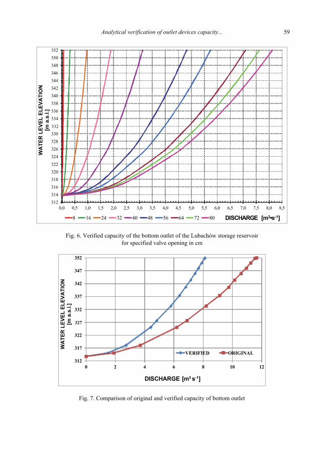
charge curves (original design), particularly in the case of small openings of the gateat the mouth of the conduit. This results from the fact that local losses in the case ofsmall opening are significant, influencing essentially the value of discharge coeffi-cient. Verified results of calculation in a graphical relation of water level elevationand gate opening degree from tailwater, are shown in Fig. 6. For fully opened gateat mouth of conduit and for water level in reservoir at 352.0 m a.s.l., capacity forthis device equals 8.125 m3 s–1. Simultaneously, in Fig. 7 a comparison of currentlyvalid discharge with verified one is shown, for fully opened gate and water level at352.0 m a.s.l.
The moment the four conduits of intermediate outlets start working under con-ditions of damming up level at 350.0 m a.s.l. (spillway crest elevation) and thegates are fully opened, the outflow equals 85 m3 s–1, which means that outflowfrom bottom outlets still remains not submerged. Just when spillway openings startoperating, downstream water level gradually rises. This causes a change of out-flow character from not submerged to submerged one, which is equivalent toa change of hydraulic conditions of bottom outlets operating. It should be calcu-lated from [5]
strhH Σ≥ (2)
where:H – head, calculated as a difference between water level elevation in reservoir
and tailwater level,hstr – sum of local and length losses, calculated for the above case.From the above condition after transformation a flow velocity is determined;
velocity is smaller if tailwater level is higher. Subsequently a discharge is calcu-lated.
Analytical verification of outlet devices capacity... 59
Fig. 6. Verified capacity of the bottom outlet of the Lubachów storage reservoirfor specified valve opening in cm
312
317
322
327
332
337
342
347
352
0 2 4 6 8 10 12WATERLEVEL ELEVA T I O N
[m a.s.l.]
DISCHARGE [m3 s-1]
VERIFIED ORIGINAL
Fig. 7. Comparison of original and verified capacity of bottom outlet
332
WA
TER
LEV
EL E
LEVA
TIO
N[m
a.s
.l.]
327
WA
TER
LEV
EL E
LEVA
TIO
N[m
a.s
.l.]
J. MACHAJSKI, D. OLEARCZYK60
6.2. INTERMEDIATE OUTLETS
The capacity of intermediate outlets depends on water level in reservoir, and theheight of opening of gates on each conduit. Their cross-sections change along theirlengths; at an inlet of each conduit is rectangular with 1.0 m width and 1.60 mheight, topped with slight arch finial. Along the conduit length its height graduallydecreases, which is important because of the need to maintain continuous flow inthe conduit in such way that at its mouth the cross-section area is about 1.0 m2.Hence, discharge of individual conduit was calculated, assuming a changeable inletcross-section area, depending on gate opening degree, assuming variable value ofdischarge coefficient, which for 0.20 m opening height is equal to 0.600 and 0.700for fully opened gate at inlet of intermediate conduit. The following equation wasapplied [5]–[9]
HgaBCQ 2= (3)
where:Q – discharge; m3 s–1,C – discharge coefficient,B – opening width; B = 1.0 m,a – height of gate opening,H – height of damming up, measured in relation to inlet crest.Determination of the moment the cross-section changes from an inlet to an outlet
was of major importance and at the same time the most difficult task in the analysis.This problem was solved analyzing a path of free water jet from an orifice, treating itas sharp edge. Results were compared with existing conduit cross-section contour onthe premises of Lubachów dam body. The moment of change occurs in a situationwhen water jet touches the upper edge of the cross-section so that it is completelyfilled with water.
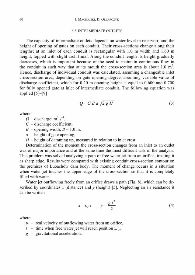
Water jet outflowing freely from an orifice draws a path (Fig. 8), which can be de-scribed by coordinates x (distance) and y (height) [5]. Neglecting an air resistance itcan be written
2
2tgytx r ==υ (4)
where:υr – real velocity of outflowing water from an orifice,t – time when free water jet will reach position x, y,g – gravitational acceleration.
Analytical verification of outlet devices capacity... 61
Fig. 8. Path of free water outflow from an orifice
Eliminating from above equations time t, we obtain
yg
x r2
2 2υ= (5)
in which
hgr 2ϕυ = (6)
where:h – position of orifice axis in relation to water level in reservoir,φ – velocity coefficient, for sharp edge orifice φ = 0.97–0.98.Analyzing a curvilinear contour of the flowing surface of intermediate outlet, it
was found to overlap the path of water jet from the completely opened orifice. Hence,it was necessary to determine a moment of change of a free flow (resulting from gateopening) into operation of completely filled intermediate outlet. It was important alsoto determine if this moment has place when a gate is partly opened and at what open-ing degree or when a gate is completely opened. At last it was determined that thismoment has place when a gate is 50% opened.
As regards the aeration problem, it was finally eliminated because its entertainmentis impossible when the cross-section of intermediate outlet is totally filled. This phe-nomenon may occur when the inflow of air is possible from the mouth side to its inte-rior. Because this phenomenon occurs only in the case of very small discharges, it wasexcluded from further considerations.
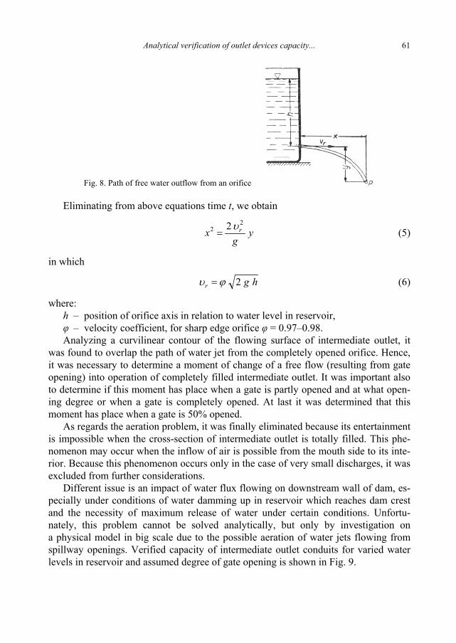
Different issue is an impact of water flux flowing on downstream wall of dam, es-pecially under conditions of water damming up in reservoir which reaches dam crestand the necessity of maximum release of water under certain conditions. Unfortu-nately, this problem cannot be solved analytically, but only by investigation ona physical model in big scale due to the possible aeration of water jets flowing fromspillway openings. Verified capacity of intermediate outlet conduits for varied waterlevels in reservoir and assumed degree of gate opening is shown in Fig. 9.
Fig. 9. Verified capacity of intermediate outlet of the Lubachów storage reservoir
332
336
340
344
348
352
0 5 10 15 20 25 30
WATERLEVEL ELEVATION
[m a.s.l.]
DISCHARGE [m3 s-1]
VERIFIED ORIGINAL
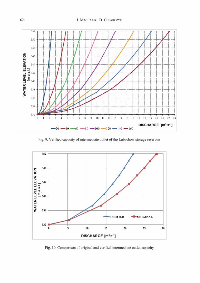
Fig. 10. Comparison of original and verified intermediate outlet capacity
WA
TER
LEV
EL E
LEVA
TIO
N[m
a.s
.l.]
340
WA
TER
LEV
EL E
LEVA
TIO
N[m
a.s
.l.]
Analytical verification of outlet devices capacity... 63
The results of calculations significantly differ from design discharge curves. Fromthe curve for fully opened gate at the mouth and assuming the lack of damping anoutflow from intermediate outlet by spillway water jet, the capacity of this device atwater level in reservoir at 352.0 m a.s.l. equals 22.150 m3 s–1. In Fig. 10, a comparisonof currently valid capacity with verified one, for fully opened gate and at water levelin reservoir at 352.0 m a.s.l. is shown.
6.3. FRONT SPILLWAY
Analyzing the capacity of front spillway openings, it has been noticed that flowcharacteristic was determined for not submerged rectangular weir. In reality, depend-ing on water level in reservoir, three flow conditions occur, differing from each other.Taking into account the geometry of opening, as given in Figs. 2 and 3, the followingtypes of flow can be distinguished, depending on the thickness of water layer thatoverflows the weir [5], [6], [9]:
– 0 < H ≤ 30 cm, free flow for rectangular cross-section with a straight insert on itscrest,
– 30 < H ≤ 130 cm, free flow through spillway with a straight insert on its crest butunder conditions of changeable width, narrowing with height,
– 130 < H ≤ 200 cm, water outflow from not submerged orifice.An interesting proposal was given by Rędowicz [2]. He based his theoretical cal-
culations of flow through a spillway opening on a method available in professionalliterature [5]. According to this method the cross-sectional area of an opening is di-vided into stripes of infinitesimal thickness dz, within which flow velocity can be as-sumed to be constant. Taking the position of a chosen strip in relation to water level inreservoir as z, then flow velocity within such strip can be calculated as
zg2=υ (7)
For discharge calculation through cross-sectional area equal to
dzzydA )(= (8)
first a specific discharge should be determined from
dzzyzgdQ )(2= (9)
and next, after integration in limits from H1 to H2, a total discharge through the cross-section of spillway opening equals
dzzzygQH
H
2/12
1
)(2 ∫= μ (10)
J. MACHAJSKI, D. OLEARCZYK64
To solve the above equation it is necessary to know function y(z). In the case of thespillway base, the solution could be expressed as follows
)(232 2/3
12/3
2 HHgbQ −= μ . (11)
350
350,4
350,8
351,2
351,6
352
0 2 4 6 8 10 12 14 16
WATER LEVELELEVATION
[m a.s.l]
DISCHARGE [m3 s-1]
VERIFIED
Fig. 11. Verified capacity of spillway of the Lubachów storage reservoir
350
350,5
351
351,5
352
0 2 4 6 8 10 12 14 16 18 20
WATER LEVEL ELEVATION
[ma.s.l.]
DISCHARGE [m3 s-1]
VERIFIED ORIGINAL
Fig. 12. Comparison of original and verified spillway capacity
WA
TER
LEV
EL E
LEVA
TIO
N[m
a.s
.l.]
WA
TER
LEV
EL E
LEVA
TIO
N[m
a.s
.l.]
352
351,5
351
350,5
350
Analytical verification of outlet devices capacity... 65
Because an equation describing a curvature of spillway opening vault is notknown, hence Rędowicz [2] proposed a division of integrated area into seven areasclose to rectangle, and next an integration of each area within some adequate limits.Obtained in that way verified capacities of spillway openings for different waterlevels in reservoir are presented in Fig. 11. Simultaneously, in Fig. 12, a comparisonof the designed capacity with verified one is shown, at water level in reservoir at352.0 m a.s.l.
7. COMPARATIVE ANALYSIS
In the table below, authors compare results obtained from calculations with originaldata determined by German designers. For comparison the capacities at damming upwater in reservoir at 352.0 m a.s.l. were taken.
Discharge Q [m3 s–1] DifferencesNo. Type
of outlet device according to archivaldischarge curves
calculatedby the authors ΔQ [m3 s–1] %
1 Bottom outlets2 × 800 mm 23.300 16.250 7.05 43.38
From the results of analytical calculations the capacity of existing outlet installa-tions is clearly seen to be overestimated nearly 30% in relation to their actual capacity.This is mainly due to the fact of the hydraulic characteristics of intermediate outflowsand front spillway being incorrectly assumed with respect to real conditions of theirfunctioning.
8. SUMMARY
The authors carried out analytical calculations to determine a capacity of outlet de-vices of the Lubachów reservoir, particularly of those elements that facilitate the ef-fective manoeuvres of water outflow, including prereleases. Based on the above, theytried to get an answer to the question of how far computational discharges can safelypass through the existing outlet devices. Unfortunately, the capacity of these deviceswas proved to be significantly overestimated, which created a crucial threat of waterflowing over the dam crest of Lubachów reservoir. Hence, in further investigations the
J. MACHAJSKI, D. OLEARCZYK66
authors made an estimation of transformations of freshet waves and conditions of theirpassage through reservoir.
REFERENCES
[1] MACHAJSKI J., OLEARCZYK D., NIEMIRSKI D., Water management directive for storage reservoirLubachów, INWDAR Wrocław, Wrocław, March, 2011 (in Polish).
[2] RĘDOWICZ W., Verification of outlet devices capacity of Lubachów dam, Materials of the Symposium“Hydrotechnika IV”, Ustroń, June, 2001 (in Polish).
[3] Directive of the Poland’s Minister of Environment of April 20, 2007, on technological conditions ofhydro-engineering structures, Dz.U. Nr 86/2007, poz. 579, (in Polish).
[4] RADCZUK L. et al., Flood protection study for the Bystrzyca river catchment, Hydrology of floodwater, Hydrological basis for flood range determination, Institute of Meteorology and Water Man-agement, Wrocław, February, 2006 (in Polish).
[5] ROGALA R., MACHAJSKI J., RĘDOWICZ W., Applied hydraulics. Calculation examples, Wrocław Uni-versity of Technology Publishers, Wrocław, 1991 (in Polish).
[6] KHATSURIA R.M., Hydraulics of Spillways and Energy Dissipators, Marcel Decker Publisher, NewYork, 2005.
[7] NOVAK P., MOFFAT A.I.B., NALLURI C., NARAYANAN R., Hydraulic Structures, Taylor & FrancisPublisher, New York, 2007.
[8] LEWIN J., Hydraulic gates and valves in free surface flow and submerged outlets, Thomas TelfordPublications, London, 1995.
[9] ŞENTÜRK F., Hydraulics of Dams and Reservoirs, Water Resources Publications, Colorado, 1994.