82
domestic commercial industrial circuit protection

domesticcommercialindustrial
circuit protection
NH INSULATED CONSUMER UNITS 4
NH METAL CONSUMER UNITS 8
CONSUMER UNIT MCBs RCBOs & FUSES 11
CONTROL DEVICES 11
CUSTOM BUILT 12
NH PHOTO VOLTAIC RANGE 14
NH DISTRIBUTION BOARDS 20
DISTRIBUTION BOARD INCOMERS 23
DISTRIBUTION BOARD MCBs & RCBOs 26
NH125 MCCB PANELBOARDS 28
NH125 OUTGOING MCCBs 33
NH125 METERS & SURGE ARRESTOR KITS 34
NH125 ACCESSORIES 35
NH250 MCCB PANELBOARDS 36
NH250 METERS & SURGE ARRESTOR KITS 41
NH250 OUTGOING MCCBs 42
NH250 ACCESSORIES 43
Founded in 1897, Wylex introducedthe first ‘consumer unit’ to theelectrical industry, this original designwas the forerunner to the ‘StandardRange’, which is still in wide use todayacross the world.From its United Kingdom base atWythenshawe, through a policy ofcontinuous design improvement,Wylex has continued to develop acomprehensive range of Domestic,Commercial and Industrial circuitprotection devices based on qualityand close attention to the practicalrequirements of the contractorincluding the fundamentalrequirements of electrical safetyembodied in the relevant latest Britishand International standards includingthe new issue and amendments of theIET Wiring Regulations.
LeftElectrium’s purpose built Commercial Centrein Cannock, Staffordshire
As a leading manufacturer of electrical domesticand industrial circuit protection products, Wylex iscommitted to the continual improvement of allquality assurance procedures and performance.
This publication has been printed
on paper that originates from a
forest that is responsibly managed,
using vegetable based inks.
NH FUSE SWITCH COMBINATION UNITS 44
SWITCH DISCONNECTORS & ISOLATORS 46
LIFELINE RCDs & ENCLOSURES 48
STANDARD RANGE 53
TECHNICAL DATA & DIMENSIONS 56
NUMERIC INDEX 76
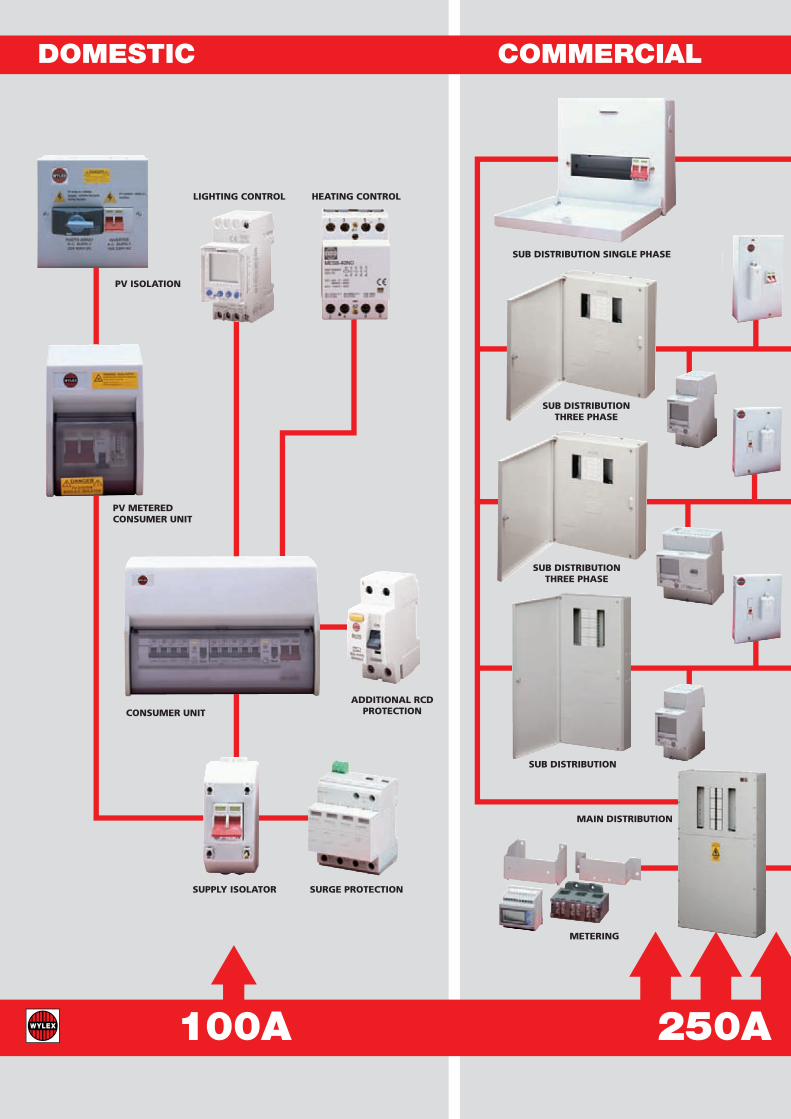
DOMESTIC COMMERCIAL
PV ISOLATION
PV METEREDCONSUMER UNIT
LIGHTING CONTROL
SUPPLY ISOLATOR SURGE PROTECTION
HEATING CONTROL
ADDITIONAL RCDPROTECTIONCONSUMER UNIT
100A 250A
METERING
SUB DISTRIBUTION SINGLE PHASE
SUB DISTRIBUTIONTHREE PHASE
SUB DISTRIBUTIONTHREE PHASE
MAIN DISTRIBUTION
SUB DISTRIBUTION

INDUSTRIAL
H&V ISOLATION
LIGHTING CONTROL
LIFT ISOLATION
CONSUMER UNIT
CONSUMER UNIT
CONSUMER UNIT
630A
MAIN ISOLATION
LOCAL ISOLATION
SUB DISTRIBUTIONTHREE PHASE
INTEGRAL METERING
SURGE PROTECTION
SUB DISTRIBUTIONTHREE PHASE
METERING
METERING
MAINDISTRIBUTION
SUB DISTRIBUTION SINGLE PHASE
SUB DISTRIBUTION
LOCAL ISOLATION

EDITIONFor details on the application to meetthe 17th edition wiring regulationsplease refer to page 59.
1st AMENDMENT
The NH range of consumer units providescontemporary styling with particular attentionto generous cable preparation room, suppliedwith incoming devices and two busbar options“fixed” for quick installation balcony connectionand “flexible” easily configured DIN rail designwith cut to length busbar kits. All designs areavailable as insulatedor metal cased versions
NH SOLUTION 17 RANGETo help installers comply with the amendedrequirements of 17th Edition wiring regulations,Wylex created the NH Solution 17 Range ofconsumer units providing 100% 30mA RCDprotection (if required)
l Main Switch – Complete Independent circuitsl Split Load – Half independent circuitsl High Integrity – Some independent circuitsl Dual RCD – No
independent circuits
THE NH RANGE Solution
NH PHOTO VOLTAIC RANGEThe ever changing needs of end users, as they
try to reduce their energy consumption andreduce their carbon foot print: has lead to the
development for all of our NH Solution 17Consumer Unit designs to be adapted for the
addition of a separate micro generationsupply e.g. Solar Photo Voltaic.

NH804
NHRS6604
NHRS12SL
NHRS44204
With DINAccessorySection
5
NH Insulated R
ange
MAIN SWITCH
CAT REF MS RATING * WAYS DIN MODULES
NH204/40 40A 2NH204/63 63A 2NH504 100A 5NH804 100A 8NH1104 100A 11NH1404 100A 14NH1904 100A 19NH504+3 100A 5 3NH804+3 100A 8 3NH804+6 100A 8 6NH1104+3 100A 11 3
Flexible - comb busbar and full DIN rail MS units available Suffix catalogue ref with FLEX e.g. NH804FLEX
SPLIT LOAD
CAT REF RCD RATING MCB WAYS MS RATING * WAYS
NHRS2404 80A 30mA 2 100A 4NHRS3304 80A 30mA 3 100A 3NHRS4204 80A 30mA 4 100A 2NHRS5404 80A 30mA 5 100A 4NHRS4504 80A 30mA 4 100A 5NHRS3604 80A 30mA 3 100A 6NHRS6304 80A 30mA 6 100A 3NHRS3904 80A 30mA 3 100A 9NHRS4804 80A 30mA 4 100A 8NHRS6604 80A 30mA 6 100A 6NHRS5704 80A 30mA 5 100A 7NHRS7504 80A 30mA 7 100A 5NHRS8404 80A 30mA 8 100A 4NHRS9304 80A 30mA 9 100A 3NHRS12504 80A 30mA 12 100A 5NHRS11604 80A 30mA 11 100A 6NHRS10704 80A 30mA 10 100A 7NHRS61104 80A 30mA 6 100A 11NHRS71004 80A 30mA 7 100A 10NHRS9804 80A 30mA 9 100A 8NHRS8904 80A 30mA 8 100A 9NHRS51204 80A 30mA 5 100A 12
FLEXIBLE SPLIT LOAD CONSUMER UNITS
CAT REF RCD RATING MCB WAYS MS RATING * WAYS * WAYS MIN MAX TOTAL
NHRS6SL 80A 30mA 2 4 100A 2 4 6NHRS9SL 80A 30mA 3 6 100A 3 6 9NHRS12SL 80A 30mA 3 9 100A 3 9 12NHRS17SL 80A 30mA 5 12 100A 5 12 17
SPLIT LOAD WITH DIN RAIL ACCESSORY SECTION
CAT REF RCD RATING MCB WAYS MS RATING * WAYS NO OF MODULES
NHRS6504+6 80A 30mA 6 100A 5 6NHRS5604+6 80A 30mA 5 100A 6 6NHRS7704+3 80A 30mA 7 100A 7 3NHRS8604+3 80A 30mA 8 100A 6 3NHRS6804+3 80A 30mA 6 100A 8 3
HIGH INTEGRITY
CAT REF 30mA 30mA MCB MCB MS * MS WAYS WAYS RATING WAYS TOTAL *
NHRS23204 2 3 100A 2 7NHRS44204 4 4 100A 2 10NHRS43304 4 3 100A 3 10NHRS33404 3 3 100A 4 10NHRS76204 7 6 100A 2 15NHRS66304 6 6 100A 3 15NHRS46504 4 6 100A 5 15NHRS55504 5 5 100A 5 15NHRS45604 4 5 100A 6 15NHRS7SSLHI 2 to 4 2 to 4 100A 1 to 4 7NHRS10SSLHI 2 to 5 2 to 5 100A 2 to 5 10NHRS15SSLHI 2 to 9 2 to 9 100A 2 to 9 15
* RCBOs or MCBs may be fitted to unprotected ways depending upon the installation requirements see page 59.
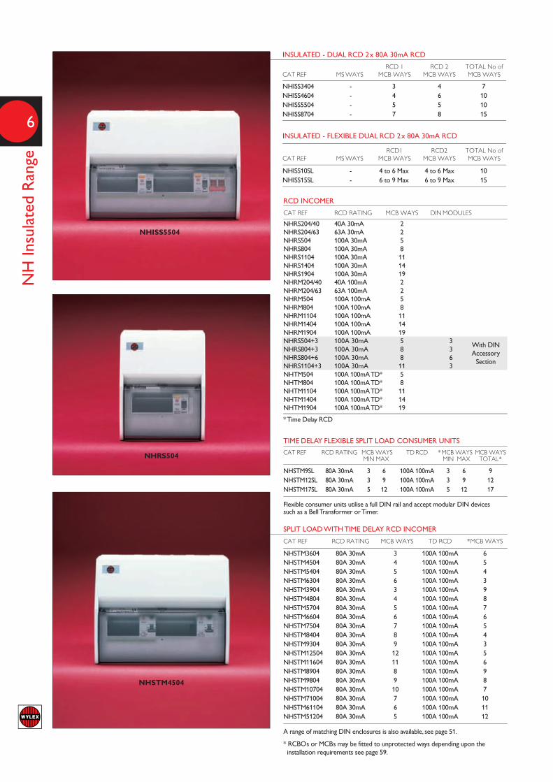
RCD INCOMER
CAT REF RCD RATING MCB WAYS DIN MODULES
NHRS204/40 40A 30mA 2NHRS204/63 63A 30mA 2NHRS504 100A 30mA 5NHRS804 100A 30mA 8NHRS1104 100A 30mA 11NHRS1404 100A 30mA 14NHRS1904 100A 30mA 19NHRM204/40 40A 100mA 2NHRM204/63 63A 100mA 2NHRM504 100A 100mA 5NHRM804 100A 100mA 8NHRM1104 100A 100mA 11NHRM1404 100A 100mA 14NHRM1904 100A 100mA 19NHRS504+3 100A 30mA 5 3NHRS804+3 100A 30mA 8 3NHRS804+6 100A 30mA 8 6NHRS1104+3 100A 30mA 11 3NHTM504 100A 100mA TD* 5NHTM804 100A 100mA TD* 8NHTM1104 100A 100mA TD* 11NHTM1404 100A 100mA TD* 14NHTM1904 100A 100mA TD* 19
* Time Delay RCD
TIME DELAY FLEXIBLE SPLIT LOAD CONSUMER UNITS
CAT REF RCD RATING MCB WAYS TD RCD *MCB WAYS MCB WAYS MIN MAX MIN MAX TOTAL*
NHSTM9SL 80A 30mA 3 6 100A 100mA 3 6 9NHSTM12SL 80A 30mA 3 9 100A 100mA 3 9 12NHSTM17SL 80A 30mA 5 12 100A 100mA 5 12 17
Flexible consumer units utilise a full DIN rail and accept modular DIN devices such as a Bell Transformer or Timer.
SPLIT LOAD WITH TIME DELAY RCD INCOMER
CAT REF RCD RATING MCB WAYS TD RCD *MCB WAYS
NHSTM3604 80A 30mA 3 100A 100mA 6NHSTM4504 80A 30mA 4 100A 100mA 5NHSTM5404 80A 30mA 5 100A 100mA 4NHSTM6304 80A 30mA 6 100A 100mA 3NHSTM3904 80A 30mA 3 100A 100mA 9NHSTM4804 80A 30mA 4 100A 100mA 8NHSTM5704 80A 30mA 5 100A 100mA 7NHSTM6604 80A 30mA 6 100A 100mA 6NHSTM7504 80A 30mA 7 100A 100mA 5NHSTM8404 80A 30mA 8 100A 100mA 4NHSTM9304 80A 30mA 9 100A 100mA 3NHSTM12504 80A 30mA 12 100A 100mA 5NHSTM11604 80A 30mA 11 100A 100mA 6NHSTM8904 80A 30mA 8 100A 100mA 9NHSTM9804 80A 30mA 9 100A 100mA 8NHSTM10704 80A 30mA 10 100A 100mA 7NHSTM71004 80A 30mA 7 100A 100mA 10NHSTM61104 80A 30mA 6 100A 100mA 11NHSTM51204 80A 30mA 5 100A 100mA 12
A range of matching DIN enclosures is also available, see page 51.
* RCBOs or MCBs may be fitted to unprotected ways depending upon the installation requirements see page 59.
INSULATED - DUAL RCD 2x 80A 30mA RCD
RCD 1 RCD 2 TOTAL No ofCAT REF MS WAYS MCB WAYS MCB WAYS MCB WAYS
NHISS3404 - 3 4 7NHISS4604 - 4 6 10NHISS5504 - 5 5 10NHISS8704 - 7 8 15
INSULATED - FLEXIBLE DUAL RCD 2x 80A 30mA RCD
RCD1 RCD2 TOTAL No ofCAT REF MS WAYS MCB WAYS MCB WAYS MCB WAYS
NHISS10SL - 4 to 6 Max 4 to 6 Max 10NHISS15SL - 6 to 9 Max 6 to 9 Max 15
6
NH Insulated Range
With DINAccessorySection
NHISS5504
NHRS504
NHSTM4504

7
NH Insulated R
ange
NH704IP
NHIIX6604
DUAL TARIFF 100A MAIN SWITCH AND 100A MAIN SWITCH
CAT REF MS RATING *WAYS MS RATING *WAYS
NHIIX5404 100A 5 100A 4NHIIX4504 100A 4 100A 5NHIIX3904 100A 3 100A 9NHIIX4804 100A 4 100A 8NHIIX7504 100A 7 100A 5NHIIX6604 100A 6 100A 6NHIIX5704 100A 5 100A 7NHIIX9804 100A 9 100A 8NHIIX8904 100A 8 100A 9NHIIX11604 100A 11 100A 6NHIIX51204 100A 5 100A 12
DUAL TARIFF 100A MAIN SWITCH AND 100A 30mA RCD MAIN SWITCH
CAT REF RCD RATING MCB WAYS MS RATING *WAYS
NHRSX5704 100A 30mA 5 100A 7NHRSX6604 100A 30mA 6 100A 6NHRSX7504 100A 30mA 7 100A 5NHRSX8904 100A 30mA 8 100A 9NHRSX9804 100A 30mA 9 100A 8
IP65 CONSUMER UNITS WITH MAIN SWITCH
CAT REF MS RATING *WAYS=
NH304IP 63A 3
NH704IP 100A 7
NH1004IP 100A 10
=2 module wide RCBOs only
IP65 CONSUMER UNITS WITH RCD INCOMER
CAT REF RCD RATING MCB WAYS
NHRS304IP 40A 30mA 3
NHRS704IP 80A 30mA 7
NHRS1004IP 80A 30mA 10
NH HOUSE BUILDERS CONSUMER UNITS
During the construction phase of a domestic property, house developers may need to have the facility to lock offthe visor and restrict the access to the consumer unit. This will be inline with their specific Health and Safetyprocedures and requirements on the construction site.
Wylex have produced a range of High Integrity ‘flexible’ consumer units that are pre drilled and blanked ready tobe fitted with a NHLDK visor locking kit and WPL padlock if required. When the property is handed over for salethe visor locking kit is easily removed by the electrical contractor, returning the consumer unit back to its originaldesign allowing complete access to the main isolator and protective devices for the house owner.
NH HOUSE BUILDERS CONSUMER UNITS
CAT REF PRODUCT
NHP-7HIFWLK 7 way High Integrity, lockable ready
NHP-10HIFWLK 10 way High Integrity, lockable ready
NHP-15HIFWLK 15 way High Integrity, lockable ready
NHLDK Visor locking kit
WPL Padlock for NHLDK
We strongly recommend that with a modified lockable visor consumerunits a separate accessible point of isolation is available for emergenciese.g. an RECSW2S isolation switch or emergency push button isolator. Itis the responsibility of the installer to ensure compliance with all relevantregulations and Health & Safety requirements of the construction site /building developer. See page 62.
8
NH Metal Cased Range
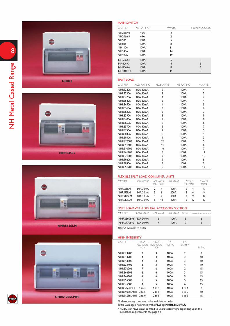
NH806
NHRS4506
NHRS12SLM
NHRS10SSLMHI
MAIN SWITCH
CAT REF MS RATING *WAYS + DIN MODULES
NH206/40 40A 2NH206/63 63A 2NH506 100A 5NH806 100A 8NH1106 100A 11NH1406 100A 14NH1906 100A 19
NH506+3 100A 5 3NH806+3 100A 8 3NH806+6 100A 8 6NH1106+3 100A 11 3
SPLIT LOAD
CAT REF RCD RATING MCB WAYS MS RATING *WAYS
NHRS2406 80A 30mA 2 100A 4NHRS3306 80A 30mA 3 100A 3NHRS4206 80A 30mA 4 100A 2NHRS5406 80A 30mA 5 100A 4NHRS4506 80A 30mA 4 100A 5NHRS3606 80A 30mA 3 100A 6NHRS6306 80A 30mA 6 100A 3NHRS3906 80A 30mA 3 100A 9NHRS4806 80A 30mA 4 100A 8NHRS6606 80A 30mA 6 100A 6NHRS5706 80A 30mA 5 100A 7NHRS7506 80A 30mA 7 100A 5NHRS8406 80A 30mA 8 100A 4NHRS9306 80A 30mA 9 100A 3NHRS12506 80A 30mA 12 100A 5NHRS11606 80A 30mA 11 100A 6NHRS10706 80A 30mA 10 100A 7NHRS61106 80A 30mA 6 100A 11NHRS71006 80A 30mA 7 100A 10NHRS9806 80A 30mA 9 100A 8NHRS8906 80A 30mA 8 100A 9NHRS51206 80A 30mA 5 100A 12
FLEXIBLE SPLIT LOAD CONSUMER UNITS
CAT REF RCD RATING MCB WAYS MS RATING *WAYS *WAYS MIN MAX MIN MAX TOTAL
NHRS6SLM 80A 30mA 2 4 100A 2 4 6NHRS9SLM 80A 30mA 3 6 100A 3 6 9NHRS12SLM 80A 30mA 3 9 100A 3 9 12NHRS17SLM 80A 30mA 5 12 100A 5 12 17
SPLIT LOAD WITH DIN RAIL ACCESSORY SECTION
CAT REF RCD RATING MCB WAYS MS RATING *WAYS No of MODULE WAYS
NHRS5606+6 80A 30mA 6 100A 5 6NHRS7706+3 80A 30mA 7 100A 7 3
100mA available to order
HIGH INTEGRITY
CAT REF 30mA 30mA MS MS RCD WAYS RCD WAYS RATING WAYS* MCB MCB TOTAL
NHRS23206 2 3 100A 2 7NHRS44206 4 4 100A 2 10NHRS43306 4 3 100A 3 10NHRS33406 3 3 100A 4 10NHRS76206 7 6 100A 2 15NHRS66306 6 6 100A 3 15NHRS46506 4 6 100A 5 15NHRS55506 5 5 100A 5 15NHRS45606 4 5 100A 6 15NHRS7SSLMHI 1 to 4 1 to 4 100A 1 to 4 7NHRS10SSLMHI 2 to 5 2 to 5 100A 2 to 5 10NHRS15SSLMHI 2 to 9 2 to 9 100A 2 to 9 15
Flush mounting consumer units available to order. Suffix Catalogue Reference with /FLU eg: NHRS6606/FLU* RCBOs or MCBs may be fitted to unprotected ways depending upon the installation requirements see page 59.
RCD INCOMER
CAT REF RCD RATING MCB WAYS
NHRS206/40 40A 30mA 2NHRS206/63 63A 30mA 2NHRS506 100A 30mA 5NHRS806 100A 30mA 8NHRS1106 100A 30mA 11NHRM206/40 40A 100mA 2NHRM206/63 63A 100mA 2NHRM506 100A 100mA 5NHRM806 100A 100mA 8NHRM1106 100A 100mA 11NHTM506 100A 100mA time delay 5NHTM806 100A 100mA time delay 8NHTM1106 100A 100mA time delay 11
9
NH Metal C
ased Range
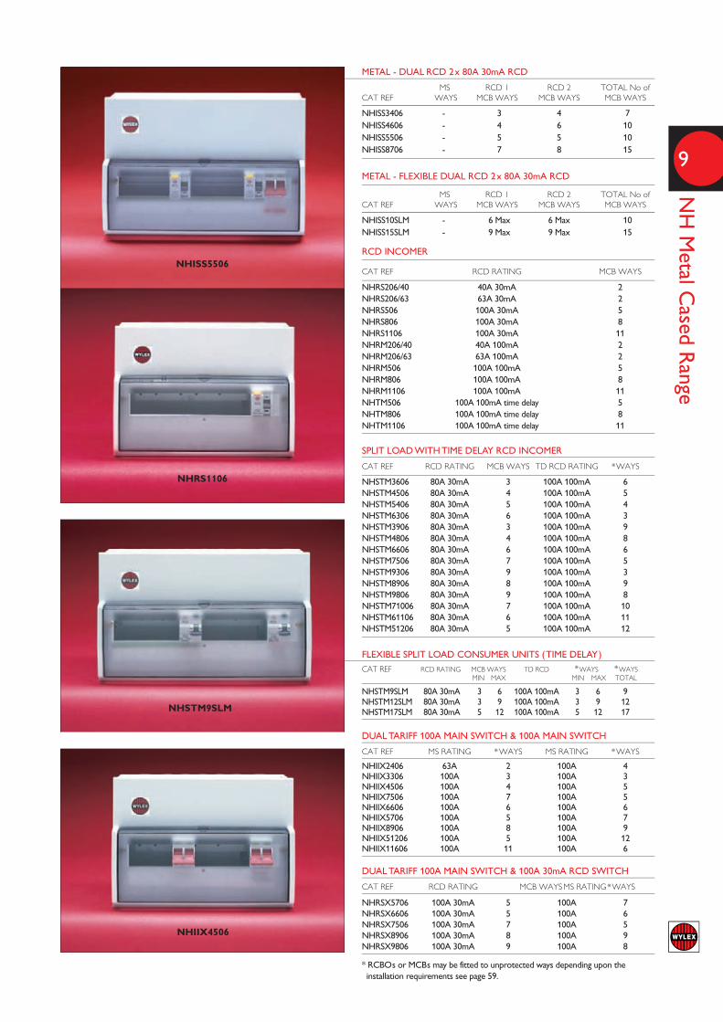
METAL - DUAL RCD 2x 80A 30mA RCD
MS RCD 1 RCD 2 TOTAL No ofCAT REF WAYS MCB WAYS MCB WAYS MCB WAYS
NHISS3406 - 3 4 7NHISS4606 - 4 6 10NHISS5506 - 5 5 10NHISS8706 - 7 8 15
METAL - FLEXIBLE DUAL RCD 2x 80A 30mA RCD
MS RCD 1 RCD 2 TOTAL No ofCAT REF WAYS MCB WAYS MCB WAYS MCB WAYS
NHISS10SLM - 6 Max 6 Max 10NHISS15SLM - 9 Max 9 Max 15
NHISS5506
NHRS1106
NHSTM9SLM
SPLIT LOAD WITH TIME DELAY RCD INCOMER
CAT REF RCD RATING MCB WAYS TD RCD RATING *WAYS
NHSTM3606 80A 30mA 3 100A 100mA 6NHSTM4506 80A 30mA 4 100A 100mA 5NHSTM5406 80A 30mA 5 100A 100mA 4NHSTM6306 80A 30mA 6 100A 100mA 3NHSTM3906 80A 30mA 3 100A 100mA 9NHSTM4806 80A 30mA 4 100A 100mA 8NHSTM6606 80A 30mA 6 100A 100mA 6NHSTM7506 80A 30mA 7 100A 100mA 5NHSTM9306 80A 30mA 9 100A 100mA 3NHSTM8906 80A 30mA 8 100A 100mA 9NHSTM9806 80A 30mA 9 100A 100mA 8NHSTM71006 80A 30mA 7 100A 100mA 10NHSTM61106 80A 30mA 6 100A 100mA 11NHSTM51206 80A 30mA 5 100A 100mA 12
FLEXIBLE SPLIT LOAD CONSUMER UNITS (TIME DELAY)
CAT REF RCD RATING MCB WAYS TD RCD *WAYS *WAYS MIN MAX MIN MAX TOTAL
NHSTM9SLM 80A 30mA 3 6 100A 100mA 3 6 9NHSTM12SLM 80A 30mA 3 9 100A 100mA 3 9 12NHSTM17SLM 80A 30mA 5 12 100A 100mA 5 12 17
DUAL TARIFF 100A MAIN SWITCH & 100A MAIN SWITCH
CAT REF MS RATING *WAYS MS RATING *WAYS
NHIIX2406 63A 2 100A 4NHIIX3306 100A 3 100A 3NHIIX4506 100A 4 100A 5NHIIX7506 100A 7 100A 5NHIIX6606 100A 6 100A 6NHIIX5706 100A 5 100A 7NHIIX8906 100A 8 100A 9NHIIX51206 100A 5 100A 12NHIIX11606 100A 11 100A 6
DUAL TARIFF 100A MAIN SWITCH & 100A 30mA RCD SWITCH
CAT REF RCD RATING MCB WAYSMS RATING*WAYS
NHRSX5706 100A 30mA 5 100A 7NHRSX6606 100A 30mA 5 100A 6NHRSX7506 100A 30mA 7 100A 5NHRSX8906 100A 30mA 8 100A 9NHRSX9806 100A 30mA 9 100A 8
* RCBOs or MCBs may be fitted to unprotected ways depending upon the installation requirements see page 59.
NHIIX4506

MAIN SWITCHCAT REF 80A 30mA 80A 30mA MS RCD WAYS RCD WAYS RATING *WAYS TOTAL
FALNH806 - - 100A 8 8FALNH1206 - - 100A 12 12FALNH1706 - - 100A 17 17
SPLIT LOAD
FALNHRS10SL - Flexi 100A Flexi 10FALNHRS15SL - Flexi 100A Flexi 15
HIGH INTEGRITY
FALNHRS10SSL Flexi Flexi 100A Flexi 10FALNHRS13SSL Flexi Flexi 100A Flexi 13FALNHRS76206 7 6 100A 2 15
DUAL SPLIT LOAD RCD
FALNHISS10SL Flexi Flexi 100A - 10FALNHISS15SL Flexi Flexi 100A - 15FALNHISS4606 4 6 100A - 10FALNHISS5506 5 5 100A - 10FALNHISS8706 8 7 100A - 15
RCD INCOMERCAT REF 100A 30mA RCD WAYS TOTAL
FALNHRS706 7 7FALNHRS1106 11 11
* RCBOs or MCBs may be fitted to unprotected ways depending upon the installation requirements see page 59.
METAL - SPLIT LOAD DUPLEX
TOP BANK BOTTOM BANKCAT REF MS RATING *WAYS RCD RATING MCB WAYS
NHDIS88 100A 8 80A 30mA 8NHDIS1111 100A 11 80A 30mA 11
METAL-HIGH INTEGRITY DUPLEX 2xRCDS, 1x 100A MAIN SWITCHCAT REF 80A 30mA 80A 30mA 80A 30mA MS RCD WAYS RCD WAYS RCD WAYS *WAYS BOTTOM BANK BOTTOM BANK TOP BANK TOTAL
NHDRS14SSLHI - 8 Flexi Flexi 14NHDRS20SSLHI - 11 Flexi Flexi 20NHDRS26SSLHI - 14 Flexi Flexi 26NHDRS36SSLHI - 19 Flexi Flexi 36
METAL - HIGH INTEGRITY DUPLEX 3xRCDS, 1x 100A MAIN SWITCHCAT REF 80A 30mA 80A 30mA 80A 30mA MS RCD WAYS RCD WAYS RCD WAYS *WAYS BOTTOM BANK BOTTOM BANK TOP BANK TOTAL
NHDRS12HI Flexi Flexi Flexi Flexi 12NHDRS18HI Flexi Flexi Flexi Flexi 18NHDRS24HI Flexi Flexi Flexi Flexi 24NHDRS34HI Flexi Flexi Flexi Flexi 34
METAL - DUAL RCD DUPLEX 2 xRCDS, 100A MAIN SWITCH
BOTTOM BANK TOP BANK TOTAL 80A 30mA 80A 30mA 80A 30mA MSCAT REF RCD WAYS RCD WAYS RCD WAYS WAYS
NHDISS119 - 11 9 - 20NHDISS1214 - 14 12 - 26
METAL - DUAL TARIFF DUPLEX
TOP BANK BOTTOM BANKCAT REF MS RATING *WAYS MS RATING *WAYS
NHDIIX88 100A 8 100A 8NHDIIX1111 100A 11 100A 11NHDIIX1414 100A 14 100A 14NHDIIX1919 100A 19 100A 19
CAT REF MS RATING *WAYS RCD RATING MCB WAYS
NHDISX88 100A 8 80A 30mA 8NHDISX1111 100A 11 80A 30mA 11
10
Metal Cased Range
FALNHR10SL
NHDIS1111
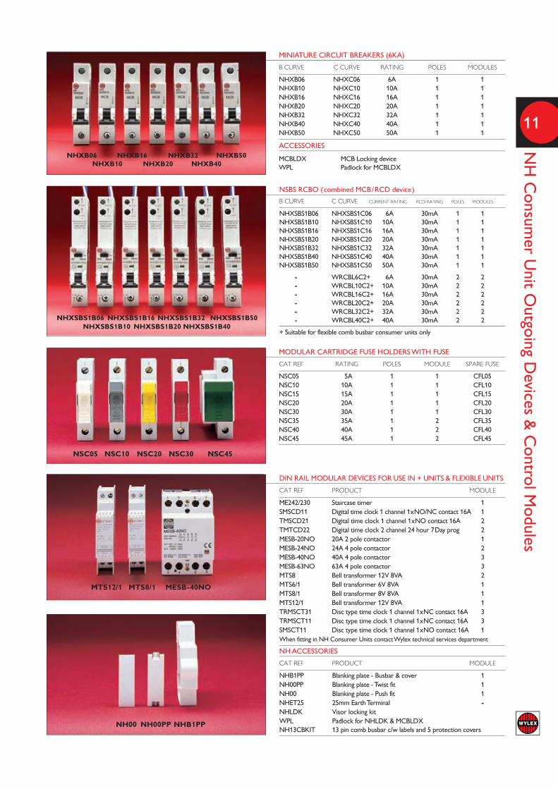
DIN RAIL MODULAR DEVICES FOR USE IN + UNITS & FLEXIBLE UNITS
CAT REF PRODUCT MODULE
ME242/230 Staircase timer 1SMSCD11 Digital time clock 1 channel 1xNO/NC contact 16A 1TMSCD21 Digital time clock 1 channel 1xNO contact 16A 2TMTCD22 Digital time clock 2 channel 24 hour 7Day prog 2MESB-20NO 20A 2 pole contactor 1MESB-24NO 24A 4 pole contactor 2MESB-40NO 40A 4 pole contactor 3MESB-63NO 63A 4 pole contactor 3MTS8 Bell transformer 12V 8VA 2MTS6/1 Bell transformer 6V 8VA 1MTS8/1 Bell transformer 8V 8VA 1MTS12/1 Bell transformer 12V 8VA 1TRMSCT31 Disc type time clock 1 channel 1xNC contact 16A 3TRMSCT11 Disc type time clock 1 channel 1xNC contact 16A 3SMSCT11 Disc type time clock 1 channel 1xNO contact 16A 1When fitting in NH Consumer Units contact Wylex technical services department
NH ACCESSORIES
CAT REF PRODUCT MODULE
NHB1PP Blanking plate - Busbar & cover 1NH00PP Blanking plate - Twist fit 1NH00 Blanking plate - Push fit 1NHET25 25mm Earth Terminal -NHLDK Visor locking kit WPL Padlock for NHLDK & MCBLDXNH13CBKIT 13 pin comb busbar c/w labels and 5 protection covers
11
NH Consum
er Unit O
utgoing Devices &
Control M
odules
MINIATURE CIRCUIT BREAKERS (6KA)
B CURVE C CURVE RATING POLES MODULES
NHXB06 NHXC06 6A 1 1NHXB10 NHXC10 10A 1 1NHXB16 NHXC16 16A 1 1NHXB20 NHXC20 20A 1 1NHXB32 NHXC32 32A 1 1NHXB40 NHXC40 40A 1 1NHXB50 NHXC50 50A 1 1
ACCESSORIES
MCBLDX MCB Locking device WPL Padlock for MCBLDX
MODULAR CARTRIDGE FUSE HOLDERS WITH FUSE
CAT REF RATING POLES MODULE SPARE FUSE
NSC05 5A 1 1 CFL05NSC10 10A 1 1 CFL10NSC15 15A 1 1 CFL15NSC20 20A 1 1 CFL20NSC30 30A 1 1 CFL30NSC35 35A 1 2 CFL35NSC40 40A 1 2 CFL40NSC45 45A 1 2 CFL45
NSBS RCBO (combined MCB/RCD device)
B CURVE C CURVE CURRENT RATING RCD RATING POLES MODULES
NHXSBS1B06 NHXSBS1C06 6A 30mA 1 1NHXSBS1B10 NHXSBS1C10 10A 30mA 1 1NHXSBS1B16 NHXSBS1C16 16A 30mA 1 1NHXSBS1B20 NHXSBS1C20 20A 30mA 1 1NHXSBS1B32 NHXSBS1C32 32A 30mA 1 1NHXSBS1B40 NHXSBS1C40 40A 30mA 1 1NHXSBS1B50 NHXSBS1C50 50A 30mA 1 1
- WRCBL6C2+ 6A 30mA 2 2 - WRCBL10C2+ 10A 30mA 2 2 - WRCBL16C2+ 16A 30mA 2 2 - WRCBL20C2+ 20A 30mA 2 2 - WRCBL32C2+ 32A 30mA 2 2 - WRCBL40C2+ 40A 30mA 2 2
+ Suitable for flexible comb busbar consumer units only
NHXB06 NHXB16 NHXB32 NHXB50 NHXB10 NHXB20 NHXB40
NSC05 NSC10 NSC20 NSC30 NSC45
NH00 NH00PP NHB1PP
MTS12/1 MTS8/1 MESB-40NO
NHXSBS1B06 NHXSBS1B16 NHXSBS1B32 NHXSBS1B50 NHXSBS1B10 NHXSBS1B20 NHXSBS1B40

CUSTOM BUILTTo meet the ever changing requirements anddesigns of the modern electrical installation,Wylex offers a service to the electricalinstaller for all the catalogued NH range ofproducts - Consumer Units, and DistributionBoards to be modified and assembled totheir own particular specification andmeeting specific customer needs.
The levels of adaptation may vary from thebasic pre-population and assembly ofoutgoing protective devices MCBs, RCBOsinto the units with personalised labelling, to
the complete customisation and wiring ofadditional accessory devices within a unit:-for example meters, energy monitors,control switching equipment:- contactors,relays and timers, and over voltage surgeprotection devices plus almost any otherDIN rail mounted piece of electricalaccessory equipment that is available.
This Custom Built service can save time onsite, reduce labour costs, and help achieveearly completion & ultimately save moneyfor the installer of these units.

13
Custom
Built
SURGE PROTECTION DEVICES
Consumer unit fitted with a Wylex Type 2 Surge ProtectionDevice (SPD) connected at the main switch.
Wylex have a range of Type 1 and Type 2 SPDs that can befitted into any single or three phase distribution unit. Theseoffer protection against over voltage surges from lightning ortransient switching voltage surges. This is inline with the newsections 534 and 443 of the amended 17th edition wiringregulations
Surge protection unit
METERING - ENERGY MONITORS
Consumer unit fitted with an ‘Efergy’ Energy Monitor;connected within the consumer unit is a current transformerand mains fed transmitter that sends the energy usage‘wireless’ to a separate ‘Efergy’ Elite or E2 energy displaymonitor.
Consumers can see how much energy they are using and costin real time, which helps them to save energy and reduce theircarbon foot print with instantaneous readings as electricalitems are switched off or turned down
Wireless Energy Monitored unit
PREWIRED PLUG-IN CONNECTORS
Consumer unit fitted with plug in connectors pre wired toeach MCB that has been specifically manufactured forprefabricated wiring / modular wiring systems.
Prefabricated / Offsite constructed buildings are becoming amore popular method of manufacture as developers strive toreduce costs, save energy and time for building construction atsite. These prefabricated modular wiring systems commonlyknown as a “plug and play” wiring, are used extensively for thistype of construction allowing quick and instantaneousconnection of consumer units & distribution boards withinthe building .
Plug and play unit
COMPLETE ENERGY CONTROL
This High Integrity duplex metal consumer unit fitted with aType 1 SPD connected at the main switch, a 20A contactor, 7 day digital time clock, 1 channel disc type time clock, and asecondary MID Meter.
The SPD offers protection against lightning strikes as this 3 storey apartment is fitted with a lightning conductor. Therewas a requirement for outdoor lighting control and timedcircuits plus the MID meter was monitoring half the circuits inthe consumer unit because these were feeding a sub lettingwithin the property.
Custom built duplex unit
The following examples are all pre-populated consumer units fitted with various ratings of MCBs and RCBOs plusadditional accessory equipment as described:-

NH PHOTO VOLTAIC RANGE
EDITIONFor details on the application to meetthe 17th edition wiring regulationsplease refer to page 59.
1st AMENDMENT

Wylex have created a number of new consumer units and Photo Voltaic dedicated circuit protectionsolutions to help installers to economically and efficiently install systems to meet the growingdemand of Small Scale Embedded Generators commonly known as Micro Generation of which themost popular for domestic premises is Solar Photovoltaic systems up to 4kW.
l AC & DC Enclosed Isolatorsl Combination DC/AC PV inverter Isolators options in single enclosurel Dual Supply PV & Grid Mains supply switchl PV add on extension consumer unitsl PV ready NH Solution 17 consumer unitsl Plug in DC solar panel cable connection options
available for all units
All four of the NH Solution 17Consumer Unit designs are available as
PV ready units incorporating the additionalequipment necessary to meet the specific regulations
for Micro Generation feeds supplied back into theDistribution Network Operator supply.
l MID approved Generation Meters l Additional Micro Generation independent circuit protectionl Additional Micro generation isolation (with padlocking facility)
16
NH Photo Voltaic
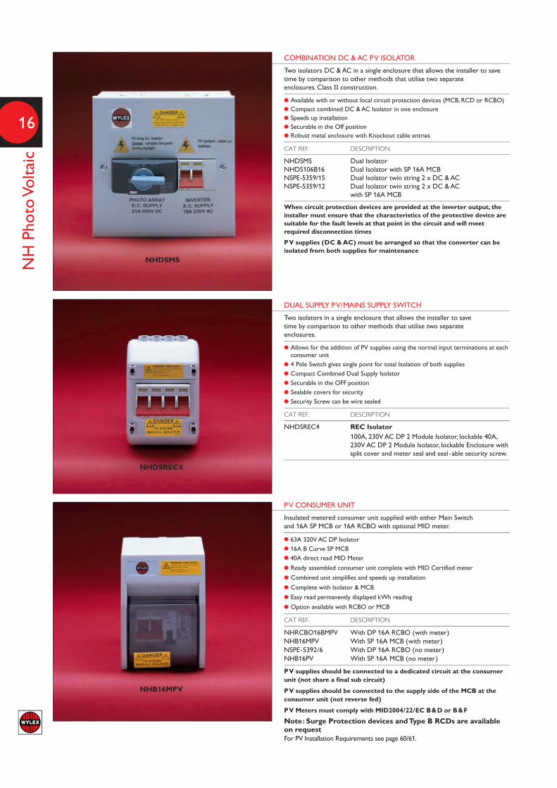
COMBINATION DC & AC PV ISOLATORTwo isolators DC & AC in a single enclosure that allows the installer to savetime by comparison to other methods that utilise two separateenclosures. Class II construction.
l Available with or without local circuit protection devices (MCB, RCD or RCBO) l Compact combined DC & AC Isolator in one enclosure l Speeds up installation l Securable in the Off position l Robust metal enclosure with Knockout cable entries
CAT REF. DESCRIPTION
NHDSMS Dual Isolator NHDS106B16 Dual Isolator with SP 16A MCBNSPE-5359/15 Dual Isolator twin string 2 x DC & ACNSPE-5359/12 Dual Isolator twin string 2 x DC & AC
with SP 16A MCB
When circuit protection devices are provided at the inverter output, theinstaller must ensure that the characteristics of the protective device aresuitable for the fault levels at that point in the circuit and will meetrequired disconnection times
PV supplies (DC & AC) must be arranged so that the converter can beisolated from both supplies for maintenance
DUAL SUPPLY PV/MAINS SUPPLY SWITCH
Two isolators in a single enclosure that allows the installer to savetime by comparison to other methods that utilise two separateenclosures.
l Allows for the addition of PV supplies using the normal input terminations at eachconsumer unit
l 4 Pole Switch gives single point for total Isolation of both suppliesl Compact Combined Dual Supply Isolatorl Securable in the OFF positionl Sealable covers for securityl Security Screw can be wire sealed
CAT REF. DESCRIPTION
NHDSREC4 REC Isolator100A, 230V AC DP 2 Module Isolator, lockable 40A,230V AC DP 2 Module Isolator, lockable Enclosure withsplit cover and meter seal and seal -able security screw.
PV CONSUMER UNIT
Insulated metered consumer unit supplied with either Main Switchand 16A SP MCB or 16A RCBO with optional MID meter.
l 63A 320V AC DP Isolatorl 16A B Curve SP MCBl 40A direct read MID Meter.
l Ready assembled consumer unit complete with MID Certified meter
l Combined unit simplifies and speeds up installation
l Complete with Isolator & MCB
l Easy read permanently displayed kWh reading
l Option available with RCBO or MCB
CAT REF. DESCRIPTION
NHRCBO16BMPV With DP 16A RCBO (with meter)NHB16MPV With SP 16A MCB (with meter)NSPE-5392/6 With DP 16A RCBO (no meter)NHB16PV With SP 16A MCB (no meter)
PV supplies should be connected to a dedicated circuit at the consumerunit (not share a final sub circuit)
PV supplies should be connected to the supply side of the MCB at theconsumer unit (not reverse fed)
PV Meters must comply with MID2004/22/EC B&D or B&F
Note: Surge Protection devices and Type B RCDs are availableon requestFor PV Installation Requirements see page 60/61.
NHDSMS
NHDSREC4
NHB16MPV

17
NH Photo Voltaic
Note: Surge Protection devices and Type B RCDs are availableon requestFor PV Installation Requirements see page 60/61.
MID METERS IN ENCLOSURE
MID B&D certified meters c/w an IP40 insulated enclosure.
l Direct connected kWh meterl Mechanical barell number or Liquid Crystal Displayl Pulsed output for BMS monitoringl DIN Rail mounting
CAT REF. DESCRIPTION
NHSPMTRA 1 Mod MID Meter (Analogue)NHSPMTRD 1 Mod MID Meter (Digital)
AC ISOLATOR
AC Isolator in an all insulated IP65 enclosure with rotary doorinterlock and padlock locking Off facility.
l Multi Polel 16, 25 or 32A, AC 21 & AC 23 ratedl 230V ACl IP65 Enclosurel Rotary Handle & padlock ‘Off ’ facility
CAT REF. DESCRIPTION
NHTPSD16 16A 230V AC 3 Pole
NHTPSD25 25A 230V AC 3 Pole
NHTPSD32 32A 230V AC 3 Pole
DC ISOLATOR
DC Isolator in an all insulated enclosure with rotary handle andpadlock locking Off facility.
l Multi Polel 25A, 32A, 40Al 500V or 600V DCl Insulated Enclosurel Rotary Handle & padlock ‘Off ’ facilityl DC-21B utilization category
CAT REF. DESCRIPTION
NHDC325004P 32A 500V 4 Pole
NHDC405004P 40A 500V 4 Pole
NHDC256006P 25A 600V 6 Pole
NHDC406006P 40A 600V 6 Pole
NHSPMTRA NHSPMTRD
NHTPSD32 NHTPSD25
NHDC406006P NHDC405004P
18
NH Photo Voltaic
NH14DSRCBMPVF
NH12DSRCBMPVSL
NH10DSRCBMPVHI
NH10DSRCBMPVDR
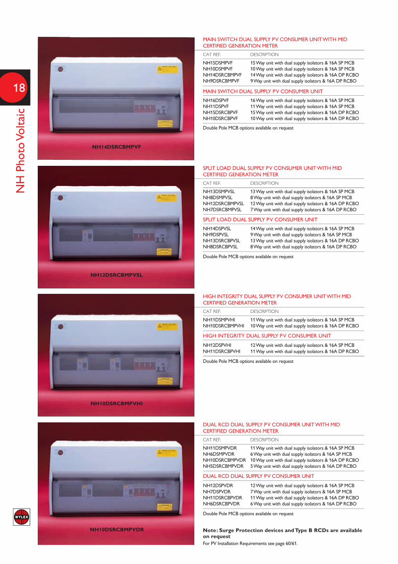
MAIN SWITCH DUAL SUPPLY PV CONSUMER UNIT WITH MID CERTIFIED GENERATION METER
CAT REF. DESCRIPTION
NH15DSMPVF 15 Way unit with dual supply isolators & 16A SP MCB NH10DSMPVF 10 Way unit with dual supply isolators & 16A SP MCB NH14DSRCBMPVF 14 Way unit with dual supply isolators & 16A DP RCBO NH9DSRCBMPVF 9 Way unit with dual supply isolators & 16A DP RCBO
MAIN SWITCH DUAL SUPPLY PV CONSUMER UNIT
NH16DSPVF 16 Way unit with dual supply isolators & 16A SP MCB NH11DSPVF 11 Way unit with dual supply isolators & 16A SP MCB NH15DSRCBPVF 15 Way unit with dual supply isolators & 16A DP RCBO NH10DSRCBPVF 10 Way unit with dual supply isolators & 16A DP RCBO
Double Pole MCB options available on request
SPLIT LOAD DUAL SUPPLY PV CONSUMER UNIT WITH MID CERTIFIED GENERATION METER
CAT REF. DESCRIPTION
NH13DSMPVSL 13 Way unit with dual supply isolators & 16A SP MCBNH8DSMPVSL 8 Way unit with dual supply isolators & 16A SP MCB NH12DSRCBMPVSL 12 Way unit with dual supply isolators & 16A DP RCBONH7DSRCBMPVSL 7 Way unit with dual supply isolators & 16A DP RCBO
SPLIT LOAD DUAL SUPPLY PV CONSUMER UNIT
NH14DSPVSL 14 Way unit with dual supply isolators & 16A SP MCBNH9DSPVSL 9 Way unit with dual supply isolators & 16A SP MCB NH13DSRCBPVSL 13 Way unit with dual supply isolators & 16A DP RCBONH8DSRCBPVSL 8 Way unit with dual supply isolators & 16A DP RCBO
Double Pole MCB options available on request
HIGH INTEGRITY DUAL SUPPLY PV CONSUMER UNIT WITH MID CERTIFIED GENERATION METER
CAT REF. DESCRIPTION
NH11DSMPVHI 11 Way unit with dual supply isolators & 16A SP MCBNH10DSRCBMPVHI 10 Way unit with dual supply isolators & 16A DP RCBO
HIGH INTEGRITY DUAL SUPPLY PV CONSUMER UNIT
NH12DSPVHI 12 Way unit with dual supply isolators & 16A SP MCBNH11DSRCBPVHI 11 Way unit with dual supply isolators & 16A DP RCBO
Double Pole MCB options available on request
DUAL RCD DUAL SUPPLY PV CONSUMER UNIT WITH MID CERTIFIED GENERATION METER
CAT REF. DESCRIPTION
NH11DSMPVDR 11 Way unit with dual supply isolators & 16A SP MCBNH6DSMPVDR 6 Way unit with dual supply isolators & 16A SP MCBNH10DSRCBMPVDR 10 Way unit with dual supply isolators & 16A DP RCBONH5DSRCBMPVDR 5 Way unit with dual supply isolators & 16A DP RCBO
DUAL RCD DUAL SUPPLY PV CONSUMER UNIT
NH12DSPVDR 12 Way unit with dual supply isolators & 16A SP MCBNH7DSPVDR 7 Way unit with dual supply isolators & 16A SP MCB NH11DSRCBPVDR 11 Way unit with dual supply isolators & 16A DP RCBONH6DSRCBPVDR 6 Way unit with dual supply isolators & 16A DP RCBO
Double Pole MCB options available on request
Note: Surge Protection devices and Type B RCDs are availableon requestFor PV Installation Requirements see page 60/61.
19
NH Photo Voltaic
For PV Installation Requirements see page 60/61.
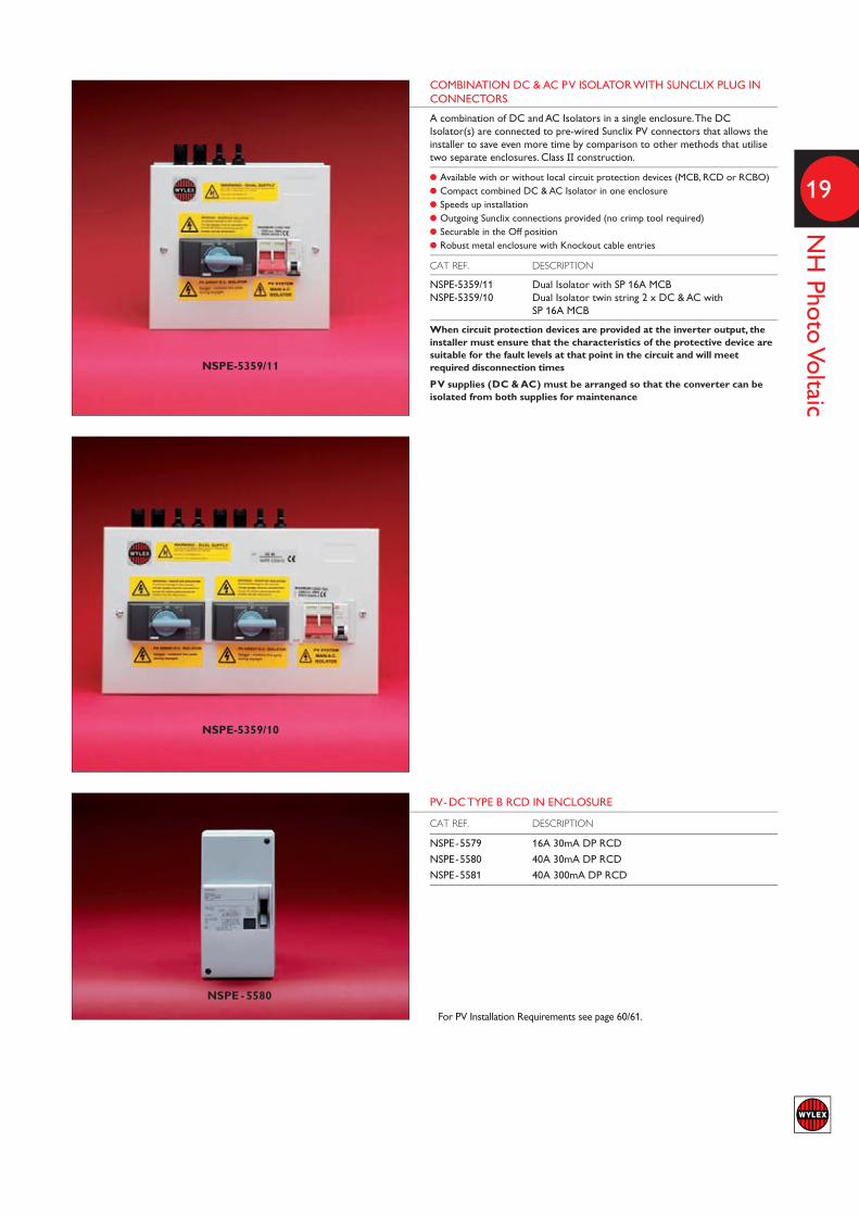
PV-DC TYPE B RCD IN ENCLOSURECAT REF. DESCRIPTION
NSPE-5579 16A 30mA DP RCD
NSPE-5580 40A 30mA DP RCD
NSPE-5581 40A 300mA DP RCD
NSPE - 5580
COMBINATION DC & AC PV ISOLATOR WITH SUNCLIX PLUG IN CONNECTORS
A combination of DC and AC Isolators in a single enclosure. The DCIsolator(s) are connected to pre-wired Sunclix PV connectors that allows theinstaller to save even more time by comparison to other methods that utilisetwo separate enclosures. Class II construction.
l Available with or without local circuit protection devices (MCB, RCD or RCBO) l Compact combined DC & AC Isolator in one enclosure l Speeds up installation l Outgoing Sunclix connections provided (no crimp tool required) l Securable in the Off position l Robust metal enclosure with Knockout cable entries
CAT REF. DESCRIPTION
NSPE-5359/11 Dual Isolator with SP 16A MCB NSPE-5359/10 Dual Isolator twin string 2 x DC & AC with
SP 16A MCB
When circuit protection devices are provided at the inverter output, theinstaller must ensure that the characteristics of the protective device aresuitable for the fault levels at that point in the circuit and will meetrequired disconnection times
PV supplies (DC & AC) must be arranged so that the converter can beisolated from both supplies for maintenance
NSPE-5359/11
NSPE-5359/10

This comprehensive collection of circuitprotection and distribution products allows thecontractor to select the most economical and electrically appropriate solutions.
l Integral metering facility
l All metal enclosures for both A Boards and B Boards
l Two frame sizes 125A and 250A B Boards
l Choice of incoming devices including SwitchDisconnector, RCDs, or Direct Connection
l B Boards accept four pole incomers (125A)
l Over 250 different boards available fromstandard catalogue items
l Removable pan assembly and glandplates for easy fixing and cable entry
l Split neutral bars help make full useof interior space and keep allterminals accessible
l Range of 10kA and 6kA MCBs
l Single pole 18mm wide RCBOstypes B or C
NH METER READYDISTRIBUTION BOARDSThe Wylex range of NH distribution Boards isdesigned to cater for a variety of industrial andcommercial applications.
The wide range of distribution boards iscomplemented by an extensive choice ofincoming devices including direct connection,switch disconnector or RCD. All TP incomingoptions allow for an integral metering option.Outgoing device options include a broadselection of MCBs and RCBOs.

TYPE ‘A’ SP & N DISTRIBUTION BOARD
CAT REF DESCRIPTION NO. OF SP WAYS
NHSPN0051 125A Distribution board Including incomer 5NHSPN0081 125A Distribution board Including incomer 8NHSPN00111 125A Distribution board Including incomer 11NHSPN00141 125A Distribution board Including incomer 14NHSPN00161 125A Distribution board Including incomer 16NHSPN00191 125A Distribution board Including incomer 19
A wide range of custom built variations are also available.Contact Wylex Technical for full details.
TYPE ‘B’ TP & N METER READY DISTRIBUTION BOARDS (Excluding Incomer)
CAT REF DESCRIPTION NO. OF TP WAYS
NHTN4MR 125A Distribution board Excluding incomer 4NHTN6MR 125A Distribution board Excluding incomer 6NHTN8MR 125A Distribution board Excluding incomer 8NHTN12MR 125A Distribution board Excluding incomer 12NHTN16MR 125A Distribution board Excluding incomer 16NHTN20MR 125A Distribution board Excluding incomer 20NHTN24MR 125A Distribution board Excluding incomer 24
Suitable for use with switch disconnector, RCD or direct connection incomer arrangementIP66TP&N MCB Distribution boards are available up to 16 TP ways
TYPE ‘B’ TP & N DISTRIBUTION BOARDS (Excluding Incomer)
CAT REF DESCRIPTION NO. OF TP WAYS
NHTN2540MR 250A Distribution board Excluding incomer 4NHTN2560MR 250A Distribution board Excluding incomer 6NHTN2580MR 250A Distribution board Excluding incomer 8NHTN25120MR 250A Distribution board Excluding incomer 12NHTN25160MR 250A Distribution board Excluding incomer 16NHTN25200MR 250A Distribution board Excluding incomer 20NHTN25240MR 250A Distribution board Excluding incomer 24
NHSPN0081
NHTN4MR
NHTN2580MR
22
NH Distribution Boards
23
NH Distribution Board Incom
ing Units &
Accessories
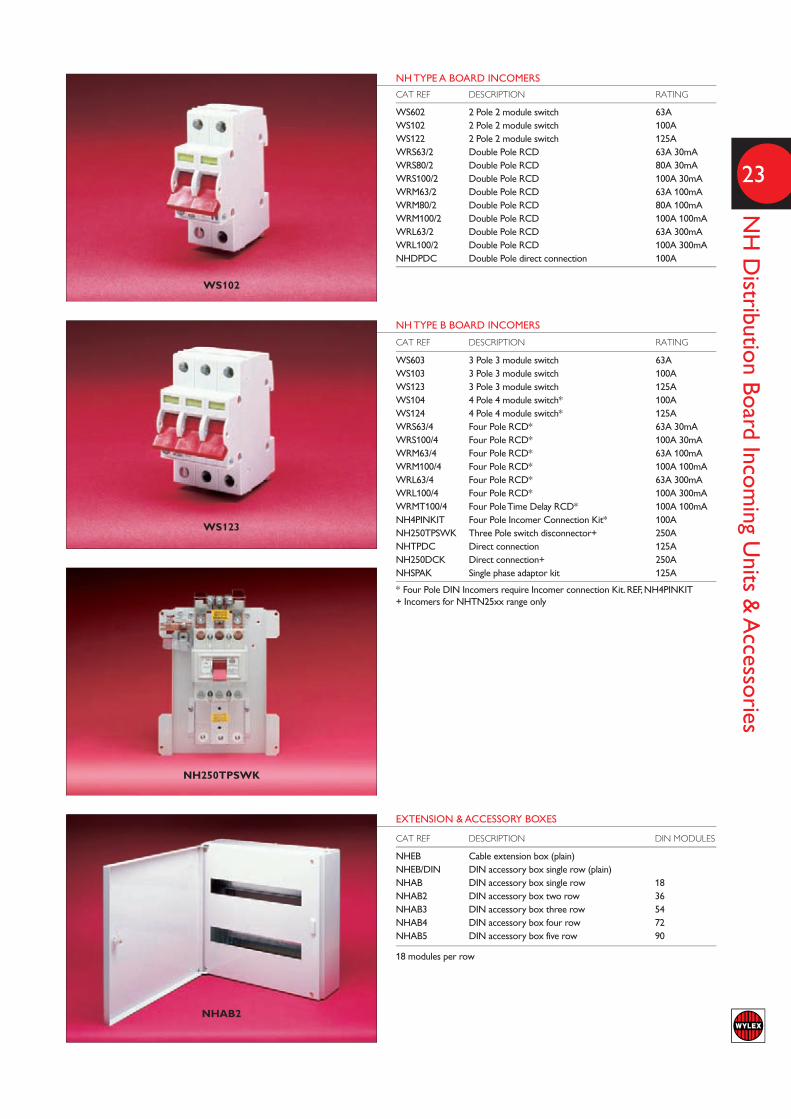
NH TYPE A BOARD INCOMERS
CAT REF DESCRIPTION RATING
WS602 2 Pole 2 module switch 63AWS102 2 Pole 2 module switch 100AWS122 2 Pole 2 module switch 125AWRS63/2 Double Pole RCD 63A 30mAWRS80/2 Double Pole RCD 80A 30mAWRS100/2 Double Pole RCD 100A 30mAWRM63/2 Double Pole RCD 63A 100mAWRM80/2 Double Pole RCD 80A 100mAWRM100/2 Double Pole RCD 100A 100mAWRL63/2 Double Pole RCD 63A 300mAWRL100/2 Double Pole RCD 100A 300mANHDPDC Double Pole direct connection 100A
WS102
WS123
NH250TPSWK
NHAB2
EXTENSION & ACCESSORY BOXES
CAT REF DESCRIPTION DIN MODULES
NHEB Cable extension box (plain) NHEB/DIN DIN accessory box single row (plain) NHAB DIN accessory box single row 18NHAB2 DIN accessory box two row 36NHAB3 DIN accessory box three row 54NHAB4 DIN accessory box four row 72NHAB5 DIN accessory box five row 90
18 modules per row
NH TYPE B BOARD INCOMERS
CAT REF DESCRIPTION RATING
WS603 3 Pole 3 module switch 63AWS103 3 Pole 3 module switch 100AWS123 3 Pole 3 module switch 125AWS104 4 Pole 4 module switch* 100AWS124 4 Pole 4 module switch* 125AWRS63/4 Four Pole RCD* 63A 30mAWRS100/4 Four Pole RCD* 100A 30mAWRM63/4 Four Pole RCD* 63A 100mAWRM100/4 Four Pole RCD* 100A 100mAWRL63/4 Four Pole RCD* 63A 300mAWRL100/4 Four Pole RCD* 100A 300mAWRMT100/4 Four Pole Time Delay RCD* 100A 100mANH4PINKIT Four Pole Incomer Connection Kit* 100ANH250TPSWK Three Pole switch disconnector+ 250ANHTPDC Direct connection 125ANH250DCK Direct connection+ 250ANHSPAK Single phase adaptor kit 125A
* Four Pole DIN Incomers require Incomer connection Kit. REF, NH4PINKIT + Incomers for NHTN25xx range only

24
NH Metering Options
NH DISTRIBUTION BOARD INTEGRAL METER KITS
CAT REF. DESCRIPTION
NHCM125INMP 125A Std Integral meter kitNHMID125INMP 125A MID Integral meter kit
l For use with 125A Type B TPN Distribution Boardsl Complete with meter, current transformers & cable looml Digital meter with kWh, amps, and volts readout
NHCM250INMP 250A Std Integral meter kitNHMID250INMP 250A MID Integral meter kit
l For use with 250A Type B TPN Distribution Boardsl Complete with meter, current transformers & cable looml Digital meter with kWh, amps, and volts readout
METER KIT EXTENSION BOXES
CAT REF. DESCRIPTION
NHTN125MP 125A Enclosed meter pack
l For use with 125A Type B TPN Distribution Boardsl Complete with meter, current transformers & cable looml Digital meter with kWh, amps, and volts readout
NHTN250MP 250A Enclosed meter pack
l For use with 250A Type B TPN Distribution Boardsl Complete with meter, current transformers & cable looml Digital meter with kWh, amps, and volts readout
For MID approved options contact Wylex Technical for full detailsNHTN125MP
NHCM125INMP
ACCESSORIES
CAT REF DESCRIPTION
NHEP11 Replacement gland plateNHBL1 1 Module blankNHBL3 3 Module blankNHBL6 6 Module blankNHBL9 9 Module blankNHBLM1 1 Module MCB dummy blankNH00PP Blanking plate - Twist fitNH18BB1 9 busbar insulatorsMCBLDX Locking device for MCBWPL Padlock for MCBLDXNHPBDL MCB Board lockPDDPL Door lock with padlocking deviceNHCEKIT 14 terminal clean earth kitNHCEKIT20 20 terminal clean earth kitNHMSL Locking device for incoming switchNHBBTOK Busbar tap off kit
MCBLDX WPL NHBL1 NH00PP NHBLM1

LIGHT AND POWER METER KIT EXTENSION BOXES
CAT REF. DESCRIPTION
NHTN125LP 125A Meter extension box
l For use with 125A Type B TPN Distribution Boardsl Complete with meter, current transformers & cable looml Digital meter with kWh, amps, and volts readout
NHTN250LP 250A Meter extension box
l For use with 250A Type B TPN Distribution Boardsl Complete with meter, current transformers & cable looml Digital meter with kWh, amps, and volts readout
For MID approved options contact Wylex Technical for full details
DUAL METERED LIGHT AND POWER BOARDS
l Suitable for use with any size of distribution board of the same ratingl 49 Distribution Board combinationsl Min 2 x 4 TP waysl Max 2 x 24 TP waysl Any two standard size distribution boards can be mounted to the L&P meteringunit to meet your specific requirements
A wide range of custom built variations are also available contact Wylex Technicalfor full details
49 different configurations can be achieved from the 7 Triple pole way standarddesign options – 4w, 6w, 8w, 12w, 16w, 20w and 24way of NH distribution boards.
Any standard size of NH unit can be combined together ranging from the 7 basiceven splits options e.g. 4w + 4w plus another 42 uneven split combinations that canbe assembled together for example the utmost combination of a 4w + 24w units.
These 49 design combinations give 17 options for the total number of combinedtriple ways ranging from 8 TP ways - 4w + 4w to a maximum of 48 TP ways - 24w+ 24w combination.
A wide range of custom built variations are also available, contact Wylex Technicalfor full details.
25
NH Metering O
ptions
MeteringMetering
MeteringMetering
4 way
Metering
4 way
6 way 6 way
24 way 24 way
8 way 8 way
12 way 12 way
16 way 16 way
20 way 20 way
MeteringMetering
MeteringMetering
4 way
Metering
4 way
6 way 6 way
24 way 24 way
8 way 8 way
12 way 12 way
16 way 16 way
20 way 20 way
NHTN125LP
NHTN125LP + 2x NHTN4

26
NH Miniature Circuit Breakers
PSB06-B PSB32-B PSB63-B
PSB206-B PSB232-B
PSB306-B PSB332-B
SINGLE POLE MCBs
RATING POLES B CURVE C CURVE D CURVE
6A 6kA 1 NSB06-B NSB06-C NSB06-D 10A 6kA 1 NSB10-B NSB10-C NSB10-D 16A 6kA 1 NSB16-B NSB16-C NSB16-D 20A 6kA 1 NSB20-B NSB20-C NSB20-D 32A 6kA 1 NSB32-B NSB32-C NSB32-D 40A 6kA 1 NSB40-B NSB40-C NSB40-D 50A 6kA 1 NSB50-B NSB50-C NSB50-D 63A 6kA 1 NSB63-B NSB63-C NSB63-D 6A 10kA 1 PSB06-B PSB06-C PSB06-D 10A 10kA 1 PSB10-B PSB10-C PSB10-D 16A 10kA 1 PSB16-B PSB16-C PSB16-D 20A 10kA 1 PSB20-B PSB20-C PSB20-D 25A 10kA 1 PSB25-B PSB25-C PSB25-D 32A 10kA 1 PSB32-B PSB32-C PSB32-D 40A 10kA 1 PSB40-B PSB40-C PSB40-D 50A 10kA 1 PSB50-B PSB50-C PSB50-D 63A 10kA 1 PSB63-B PSB63-C PSB63-D
TWO POLE MCBs
RATING POLES B CURVE C CURVE D CURVE
6A 10kA 2 PSB206-B PSB206-C PSB206-D 10A 10kA 2 PSB210-B PSB210-C PSB210-D 16A 10kA 2 PSB216-B PSB216-C PSB216-D 20A 10kA 2 PSB220-B PSB220-C PSB220-D 25A 10kA 2 PSB225-B PSB225-C PSB225-D 32A 10kA 2 PSB232-B PSB232-C PSB232-D 40A 10kA 2 PSB240-B PSB240-C PSB240-D 50A 10kA 2 PSB250-B PSB250-C PSB250-D 63A 10kA 2 PSB263-B PSB263-C PSB263-D
TRIPLE POLE MCBs
RATING POLES B CURVE C CURVE D CURVE
6A 6kA 3 NSB306-B NSB306-C NSB306-D 10A 6kA 3 NSB310-B NSB310-C NSB310-D 16A 6kA 3 NSB316-B NSB316-C NSB316-D 20A 6kA 3 NSB320-B NSB320-C NSB320-D 32A 6kA 3 NSB332-B NSB332-C NSB332-D 40A 6kA 3 NSB340-B NSB340-C NSB340-D 50A 6kA 3 NSB350-B NSB350-C NSB350-D 63A 6kA 3 NSB363-B NSB363-C NSB363-D 6A 10kA 3 PSB306-B PSB306-C PSB306-D 10A 10kA 3 PSB310-B PSB310-C PSB310-D 16A 10kA 3 PSB316-B PSB316-C PSB316-D 20A 10kA 3 PSB320-B PSB320-C PSB320-D 25A 10kA 3 PSB325-B PSB325-C PSB325-D 32A 10kA 3 PSB332-B PSB332-C PSB332-D 40A 10kA 3 PSB340-B PSB340-C PSB340-D 50A 10kA 3 PSB350-B PSB350-C PSB350-D 63A 10kA 3 PSB363-B PSB363-C PSB363-D

PSBS6/1 PSBS32/1 PSBS50/1
TMSCD21 TMTCD22 MESB-40NO
27
NH RCBOs, M
odular Devices &
Accessories
MODULAR DIN RAIL DEVICES
CAT REF. DESCRIPTION MODULE
SMSCD11 Digital Timeclock 1 channel 1xNO/NC Contact 16A 1TMSCD21 Digital Timeclock 1 channel 1xNO Contact 16A 2TMTCD22 Digital Timeclock 2 channel 2MESB-20NC 20A 2 Pole Contactor 2 x N/C 240V Coil 1MESB-20NO 20A 2 Pole Contactor 2 x N/O 240V Coil 1MESB-24NC 24A 4 Pole Contactor 4 x N/C 240V Coil 2MESB-24NO 24A 4 Pole Contactor 4 x N/O 240V Coil 2MESB-40NC 40A 4 Pole Contactor 4 x N/C 240V Coil 3MESB-40NO 40A 4 Pole Contactor 4 x N/O 240V Coil 3MESB-63NO 63A 4 Pole Contactor 4 x N/O 240V Coil 3
For use in DIN Enclosures EG: NH ED Range, Flexible CUs or ‘+’ Units
SINGLE MODULE RCBO - FOR USE IN NH TYPE A & B DISTRIBUTION BOARDS
RATING POLES RCD RATING B CURVE C CURVE
6A 10kA 1 30mA PSBS6-B/1 PSBS6/110A 10kA 1 30mA PSBS10-B/1 PSBS10/116A 10kA 1 30mA PSBS16-B/1 PSBS16/120A 10kA 1 30mA PSBS20-B/1 PSBS20/132A 10kA 1 30mA PSBS32-B/1 PSBS32/140A 10kA 1 30mA PSBS40-B/1 PSBS40/150A 10kA 1 30mA PSBS50-B/1 PSBS50/1
RCBOs with longer incoming neutral flying leads (1.2M) are available - Suffix theType C list number with LT (e.g. PSBS6/1LT)
KILOWATT HOUR METERS
CAT REF. DESCRIPTION MODULE
NHCM80SP 80A SP kWh Meter 2NHCM80TP 80A TP kWh Meter 4NHMID80SP 80A SP kWh (MID Approved) Meter 2NHMID80TP 80A TP kWh (MID Approved) Meter 4
l Direct Connected Digital kWh meterl Pulsed output for BMS monitoringl DIN Rail mountingFor use in DIN enclosures eg: NHAB
MID approval - see Technical section page 75.
NHCM80SP NHCM80TP
ACCESSORIES
CAT REF DESCRIPTION
NHEP11 Replacement gland plateNHBL1 1 Module blankNHBL3 3 Module blankNHBL6 6 Module blankNHBL9 9 Module blankNHBLM1 1 Module MCB dummy blankNH00PP Blanking plate - Twist fitNH18BB1 9 busbar insulatorsMCBLDX Locking device for MCBWPL Padlock for MCBLDXNHPBDL MCB Board lockPDDPL Door lock with padlocking deviceNHCEKIT 14 terminal clean earth kitNHCEKIT20 20 terminal clean earth kitNHMSL Locking device for incoming switchNHBBTOK Busbar tap off kit
MCBLDX WPL NHBL1 NH00PP NHBLM1

The NH125 Panelboard system offers 250Aand 400A rated, fully shrouded busbarsystems in a modular enclosure whichincludes integral incoming metering facility.
The enclosure system combined withNHGG MCCBs, outgoing metering and arange of accessories, provides a competentflexible main or sub-main panelboard.
l NHGG125 MCCBs 15A-125A ratings
l 25kA breaking capacity
l Max conductor cross sections: up to andincluding 40 amp rating - 16mm2
above 40 amp rating - 50mm2
l Comprehensive range of accessories
l Fully shrouded bus bars
l Excellent access to N/E bars for cabling
l Full or partial lockable doors
l Conforms fully with BSEN 61439-2 form 3b type 2
l Enclosure supplied with factory fittedincoming switching unit where applicable
NH125 MCCB PANELBOARDS

Panelboards(includes TP switching unit)
Panelboards(direct connection)
250A NHPBG6SW250 NHPBG8SW250 NHPBG12SW250 NHPBG16SW250400A NHPBG6SW400 NHPBG8SW400 NHPBG12SW400 NHPBG16SW400
250A NHPBG6DC250 NHPBG8DC250 NHPBG12DC250 NHPBG16DC250400A NHPBG6DC400 NHPBG8DC400 NHPBG12DC400 NHPBG16DC400
6 way8 way
12 way
16 way
6 way8 way
12 way
16 way
Overcurrent Release Modules(required for each incomer)
TP
Cableways
3 mod
12 mod
17 mod
Add-on unit NHPB3MW250A 6 Way NHPB12MW250A 8 Way NHPB13MW400A 6 Way NHPB14MW250A 12 Way/400A 8 Way NHPB15MW250A 16 Way/400A 12 Way NHPB17MW400A 16 Way NHPB19MW
Outgoing Metering
Standard MID Meter Kit Meter Kit63A NHPB63CTM -125A NHPB125CTM NHPB125CTMID
Each metering cableway of outgoing meterkits requires power supply cable NHPBOCL
CA
RLO
GA
VA
ZZI
kWh
M21
Door KitsAdd-on Units NHPBG3DRHalf door - 6 Way NHPBG5DRHalf door - 8 Way NHPBG6DRHalf door - 250A incomer NHPBG7DRHalf door - 12 Way NHPBG8DRHalf door - 400A incomer NHPBG9DRHalf door - 16 Way NHPBG10DRFull door - 250A 6 Way NHPBG12DRFull door - 250A 8 Way NHPBG13DRFull door - 400A 6 Way NHPBG14DRFull door - 250A 12 Way/400A 8 Way NHPBG15DR
Integral Lightning /Surge Protection
Combination Kit NHPBCLSALightning Arrester Kit NHPBLASurge Arrester Kit NHPBSA
Cableways
Integral Incoming Meter Kits
250A 400AStd NHPB250CTINM NHPB400CTINMMID NHPB250CTINMID NHPB400CTINMID
CA
RLO
GA
VA
ZZI
kWh
M21
Add-on Units
Add-on 100A SPN Distribution Board NHPBGDBAdd-on Control Module - 24 mod NHPBGABAdd-on 250A Panelboard Metering Kit NHPBG250MPAdd-on 400A Panelboard Metering Kit NHPBG400MPCable Spreader Box NHPBGCSB
250A 400A63A - 160A NHJ631603ELI -100A - 250A NHJ1002503ELI NHL1002503ELI160A - 400A - NHL1604003ELISwitch Disconnector NHJ2503SWDM NHL630SWDM
NHPB250CTINM Std 250A
Integral Incoming Meter Kits
NHPB400CTINMNHPB250CTINM 400A
Integral Incoming Meter Kits
M21
AZZI
kWhVC
AR
LO G
A
Add-on 250A Panelboarol Module - 24 mod Add-on Contr
Add-on 100A SPN Distribution Boar
Add-on Units
NHPBG250MPd Metering Kit Add-on 250A PanelboarNHPBGABol Module - 24 mod NHPBGDBd Add-on 100A SPN Distribution Boar
NHPBG250MPNHPBGABNHPBGDB
Surge PrIntegral Lightning /
Combination Kit
otectionSurge PrIntegral Lightning /
NHPBCLSACombination Kit
NHPBCLSA
Cableways
Cableways 17 mod
12 mod
NHPB250CTINMID MID
(includes TP switching unit)Panelboar
17 mod
NHPB400CTINMIDNHPB250CTINMID
(includes TP switching unit)dsPanelboar
eader Box Cable SprAdd-on 400A Panelboar
NHPBGCSBNHPBG400MPd Metering Kit Add-on 400A Panelboar
16 way
NHPBGCSBNHPBG400MP
ect connection)(dirdsPanelboar
12 way
8 way
ester Kit Surge ArrLightning Arr
16 way
12 way
NHPBSAester Kit NHPBLAester Kit Lightning Arr
3 mod
ay 250A 6 WAdd-on unit
3 mod
NHPB12MWay NHPB3MWAdd-on unit
6 way
NHPB12MWNHPB3MW
8 way6 way
12 way
Cableways
6 way
Cableways
8 way
ay 400A 16 Way/400A 12 W250A 16 Way/400A 8 W250A 12 W
ay 400A 6 Way 250A 8 W
Outgoing Metering
NHPB19MW ay NHPB17MWay ay/400A 12 WNHPB15MWay ay/400A 8 WNHPB14MWay NHPB13MWay
Outgoing Metering
NHPBG6SW400 400A NHPBG6SW250 250A
currOver
NHPB19MW NHPB17MWNHPB15MWNHPB14MWNHPB13MW
NHPBG8SW400 NHPBG6SW400 NHPBG8SW250 NHPBG6SW250
ent Release Modulescurr
NHPBG16SW400NHPBG12SW400 NHPBG8SW400 NHPBG16SW250NHPBG12SW250 NHPBG8SW250
ent Release Modules
NHPBG16SW400 NHPBG16SW250
Door Kits
NHPBG6DC400 400A NHPBG6DC250 250A
NHPBG12DC400 NHPBG8DC400 NHPBG12DC250 NHPBG8DC250
NHPBG16DC400NHPBG12DC400 NHPBG16DC250NHPBG12DC250
NHPBG16DC400NHPBG16DC250
NHPB125CTM 125A NHPB63CTM 63A Meter Kit Standar
Outgoing Metering
NHPB125CTMIDNHPB125CTM -NHPB63CTM Meter KitMeter Kit MIDd Standar
Outgoing Metering
M21
AZZI
kWhVC
AR
LO G
A
ed for each incomer)equir(rcurrOver
100A - 250A NHPB125CTMID63A - 160A
ed for each incomer)ent Release Modulescurr
TP
NHJ1002503ELI NHJ631603ELI 250A
ent Release Modules
NHL1002503ELI-400A
Door Kits
Full door - 400A 6 Way Full door - 250A 8 Way Full door - 250A 6 W
ay Half door - 16 WHalf door - 400A incomer
ay Half door - 12 WHalf door - 250A incomer
ay Half door - 8 Way Half door - 6 W
Add-on Units
NHPBG14DRNHPBG13DRNHPBG12DRNHPBG10DRNHPBG9DRHalf door - 400A incomer NHPBG8DRNHPBG7DRHalf door - 250A incomer NHPBG6DRNHPBG5DRNHPBG3DR
NHPBG14DRNHPBG13DRNHPBG12DRNHPBG10DRNHPBG9DRNHPBG8DRNHPBG7DRNHPBG6DRNHPBG5DRNHPBG3DR
es power supply cable NHPBOCLequirkits rEach metering cableway of outgoing meter
es power supply cable NHPBOCLEach metering cableway of outgoing meter
Switch Disconnector es power supply cable NHPBOCL
Each metering cableway of outgoing meter160A - 400A
NHJ2503SWDM Switch Disconnector -
NHL630SWDM NHL1604003ELI
ay/400A 8 WFull door - 250A 12 Way Full door - 400A 6 W
NHPBG15DRay ay/400A 8 WNHPBG14DR
NHPBG15DRNHPBG14DR
30
NH125 PANELBOARD SELECTION GUIDE

Panelboards(includes TP switching unit)
Panelboards(direct connection)
250A NHPBG6SW250 NHPBG8SW250 NHPBG12SW250 NHPBG16SW250400A NHPBG6SW400 NHPBG8SW400 NHPBG12SW400 NHPBG16SW400
250A NHPBG6DC250 NHPBG8DC250 NHPBG12DC250 NHPBG16DC250400A NHPBG6DC400 NHPBG8DC400 NHPBG12DC400 NHPBG16DC400
6 way8 way
12 way
16 way
6 way8 way
12 way
16 way
Overcurrent Release Modules(required for each incomer)
TP
Cableways
3 mod
12 mod
17 mod
Add-on unit NHPB3MW250A 6 Way NHPB12MW250A 8 Way NHPB13MW400A 6 Way NHPB14MW250A 12 Way/400A 8 Way NHPB15MW250A 16 Way/400A 12 Way NHPB17MW400A 16 Way NHPB19MW
Outgoing Metering
Standard MID Meter Kit Meter Kit63A NHPB63CTM -125A NHPB125CTM NHPB125CTMID
Each metering cableway of outgoing meterkits requires power supply cable NHPBOCL
CA
RLO
GA
VA
ZZI
kWh
M21
Door KitsAdd-on Units NHPBG3DRHalf door - 6 Way NHPBG5DRHalf door - 8 Way NHPBG6DRHalf door - 250A incomer NHPBG7DRHalf door - 12 Way NHPBG8DRHalf door - 400A incomer NHPBG9DRHalf door - 16 Way NHPBG10DRFull door - 250A 6 Way NHPBG12DRFull door - 250A 8 Way NHPBG13DRFull door - 400A 6 Way NHPBG14DRFull door - 250A 12 Way/400A 8 Way NHPBG15DR
Integral Lightning /Surge Protection
Combination Kit NHPBCLSALightning Arrester Kit NHPBLASurge Arrester Kit NHPBSA
Cableways
Integral Incoming Meter Kits
250A 400AStd NHPB250CTINM NHPB400CTINMMID NHPB250CTINMID NHPB400CTINMID
CA
RLO
GA
VA
ZZI
kWh
M21
Add-on Units
Add-on 100A SPN Distribution Board NHPBGDBAdd-on Control Module - 24 mod NHPBGABAdd-on 250A Panelboard Metering Kit NHPBG250MPAdd-on 400A Panelboard Metering Kit NHPBG400MPCable Spreader Box NHPBGCSB
250A 400A63A - 160A NHJ631603ELI -100A - 250A NHJ1002503ELI NHL1002503ELI160A - 400A - NHL1604003ELISwitch Disconnector NHJ2503SWDM NHL630SWDM
NHPB250CTINM Std 250A
Integral Incoming Meter Kits
NHPB400CTINMNHPB250CTINM 400A
Integral Incoming Meter Kits
M21
AZZI
kWhVC
AR
LO G
A
Add-on 250A Panelboarol Module - 24 mod Add-on Contr
Add-on 100A SPN Distribution Boar
Add-on Units
NHPBG250MPd Metering Kit Add-on 250A PanelboarNHPBGABol Module - 24 mod NHPBGDBd Add-on 100A SPN Distribution Boar
NHPBG250MPNHPBGABNHPBGDB
Surge PrIntegral Lightning /
Combination Kit
otectionSurge PrIntegral Lightning /
NHPBCLSACombination Kit
NHPBCLSA
Cableways
Cableways 17 mod
12 mod
NHPB250CTINMID MID
(includes TP switching unit)Panelboar
17 mod
NHPB400CTINMIDNHPB250CTINMID
(includes TP switching unit)dsPanelboar
eader Box Cable SprAdd-on 400A Panelboar
NHPBGCSBNHPBG400MPd Metering Kit Add-on 400A Panelboar
16 way
NHPBGCSBNHPBG400MP
ect connection)(dirdsPanelboar
12 way
8 way
ester Kit Surge ArrLightning Arr
16 way
12 way
NHPBSAester Kit NHPBLAester Kit Lightning Arr
3 mod
ay 250A 6 WAdd-on unit
3 mod
NHPB12MWay NHPB3MWAdd-on unit
6 way
NHPB12MWNHPB3MW
8 way6 way
12 way
Cableways
6 way
Cableways
8 way
ay 400A 16 Way/400A 12 W250A 16 Way/400A 8 W250A 12 W
ay 400A 6 Way 250A 8 W
Outgoing Metering
NHPB19MW ay NHPB17MWay ay/400A 12 WNHPB15MWay ay/400A 8 WNHPB14MWay NHPB13MWay
Outgoing Metering
NHPBG6SW400 400A NHPBG6SW250 250A
currOver
NHPB19MW NHPB17MWNHPB15MWNHPB14MWNHPB13MW
NHPBG8SW400 NHPBG6SW400 NHPBG8SW250 NHPBG6SW250
ent Release Modulescurr
NHPBG16SW400NHPBG12SW400 NHPBG8SW400 NHPBG16SW250NHPBG12SW250 NHPBG8SW250
ent Release Modules
NHPBG16SW400 NHPBG16SW250
Door Kits
NHPBG6DC400 400A NHPBG6DC250 250A
NHPBG12DC400 NHPBG8DC400 NHPBG12DC250 NHPBG8DC250
NHPBG16DC400NHPBG12DC400 NHPBG16DC250NHPBG12DC250
NHPBG16DC400NHPBG16DC250
NHPB125CTM 125A NHPB63CTM 63A Meter Kit Standar
Outgoing Metering
NHPB125CTMIDNHPB125CTM -NHPB63CTM Meter KitMeter Kit MIDd Standar
Outgoing Metering
M21
AZZI
kWhVC
AR
LO G
A
ed for each incomer)equir(rcurrOver
100A - 250A NHPB125CTMID63A - 160A
ed for each incomer)ent Release Modulescurr
TP
NHJ1002503ELI NHJ631603ELI 250A
ent Release Modules
NHL1002503ELI-400A
Door Kits
Full door - 400A 6 Way Full door - 250A 8 Way Full door - 250A 6 W
ay Half door - 16 WHalf door - 400A incomer
ay Half door - 12 WHalf door - 250A incomer
ay Half door - 8 Way Half door - 6 W
Add-on Units
NHPBG14DRNHPBG13DRNHPBG12DRNHPBG10DRNHPBG9DRHalf door - 400A incomer NHPBG8DRNHPBG7DRHalf door - 250A incomer NHPBG6DRNHPBG5DRNHPBG3DR
NHPBG14DRNHPBG13DRNHPBG12DRNHPBG10DRNHPBG9DRNHPBG8DRNHPBG7DRNHPBG6DRNHPBG5DRNHPBG3DR
es power supply cable NHPBOCLequirkits rEach metering cableway of outgoing meter
es power supply cable NHPBOCLEach metering cableway of outgoing meter
Switch Disconnector es power supply cable NHPBOCL
Each metering cableway of outgoing meter160A - 400A
NHJ2503SWDM Switch Disconnector -
NHL630SWDM NHL1604003ELI
ay/400A 8 WFull door - 250A 12 Way Full door - 400A 6 W
NHPBG15DRay ay/400A 8 WNHPBG14DR
NHPBG15DRNHPBG14DR
31

32
PANELBOARD WITH TP SWITCHING UNIT(PLUG-IN MODULE REQUIRED)
DESCRIPTION 250A CAT REF. 400A CAT REF.
6 Way NHPBG6SW250 NHPBG6SW4008 Way NHPBG8SW250 NHPBG8SW40012 Way NHPBG12SW250 NHPBG12SW40016 Way NHPBG16SW250 NHPBG16SW400
Fault rating: 25kA Icc 25kA for 1 sec
Max 4c Incoming Cu Cable Size: 150mm² see note below
Max cable lug connection: see note below 32mm wide
DIRECT CONNECTED PANELBOARDS
DESCRIPTION 250A CAT REF. 400A CAT REF.
6 Way NHPBG6DC250 NHPBG6DC4008 Way NHPBG8DC250 NHPBG8DC40012 Way NHPBG12DC250 NHPBG12DC40016 Way NHPBG16DC250 NHPBG16DC400
Fault rating: 25kA Icc 25kA for 1 sec
Max 4c Incoming Cu Cable Size: see note below see note below
Available lug connection:on 30mm wide Cu bar M8 M10
NHPBG6SW250
NHPBG8DC400
NH125 Panelboards
PLUG-IN MODULES FOR 250A INCOMER
250A CAT REF. DESCRIPTION
NHJ631603ELI 63A - 160A Overcurrent releaseNHJ1002503ELI 100A - 250A Overcurrent releaseNHJ2503SWDM 250A Switch disconnector
PLUG-IN MODULES FOR 400A INCOMER
400A CAT REF. DESCRIPTION
NHL1002503ELI 100A - 250A Overcurrent releaseNHL1604003ELI 160A - 400A Overcurrent releaseNHL630SWDM 400A Switch disconnector
NHJ1002503ELI
NHL1604003ELI
The 400A switching unit accepts cable lug connections up to 32mm wide.Dependant on the size & type of cable lug selected the potential maximum cablecapacity of the cable lug can be up to 300mm².

DOOR BLANKS
CAT REF. DESCRIPTION
NHPB1TS NHGG SP MCCB door blank withbusbar insulator
33
NH125 O
utgoing MCCBs
1 POLE OUTGOING G FRAME MCCBs
CAT REF. DESCRIPTION
NHGGPCB151 15A MCCBNHGGPCB201 20A MCCBNHGGPCB251 25A MCCBNHGGPCB301 30A MCCBNHGGPCB401 40A MCCBNHGGPCB501 50A MCCBNHGGPCB601 60A MCCBNHGGPCB801 80A MCCBNHGGPCB1001 100A MCCBNHGGPCB1251 125A MCCB
NHGGPCB201
3 POLE OUTGOING G FRAME MCCBs
CAT REF. DESCRIPTION
NHGGPCB153 15A MCCBNHGGPCB203 20A MCCBNHGGPCB253 25A MCCBNHGGPCB303 30A MCCBNHGGPCB403 40A MCCBNHGGPCB503 50A MCCBNHGGPCB603 60A MCCBNHGGPCB803 80A MCCBNHGGPCB1003 100A MCCBNHGGPCB1253 125A MCCB
NHGGPCB1253
NHPB1TS

OUTGOING METER KITS *
STANDARD CAT REF. MID CAT REF. DESCRIPTION
NHPB63CTM - 63A Energy Meter KitNHPB125CTM NHPB125CTMID 125A Energy Meter Kit
* Each metering cableway of outgoing meter kits requires: NHPBOCL Meter Kit Voltage Supply Cable Loom Current transformer internal dimensions: Standard versions: MID versions: 63A & 125A - 16mm W x 31mm H slot 125A - 21mm diameter
INCOMING INTEGRAL METER KITS
250A CAT REF. 400A CAT REF. DESCRIPTION
NHPB250CTINM NHPB400CTINM Energy Meter Kit - StandardNHPB250CTINMID NHPB400CTINMID Energy Meter Kit - MID
Each kit contains: Digital meter offering Amps, Volts, kWh readout plus pulsedoutput, block current transformer (MID option - 3CTs), fuses, mounting plates &cable looms. Supplied loose for assembly and connection by others.
Current transformer internal dimensions:Standard Versions: MID Versions:250A - 21mm W x 25mm H slot 250A - 28mm diameter400A - 31mm W x 36mm H slot 400A - 31mm W x 36mm H slot
INTEGRAL LIGHTNING & SURGE ARRESTERS
CAT REF. DESCRIPTION
NHPBCLSA Combination Lightning & Surge Arrester KitNHPBLA Lightning Arrester KitNHPBSA Surge Arrester Kit
Each kit contains: Lightning, Surge or Combination arrester, MCCB, mounting plate& cable loom. Supplied loose for assembly and connection by others. Only one ofthese three options is possible per panelboard. MCCB mounted in bottom righthand outgoing way.
NHPB250CTINM
NHPBCLSA
NHPB125CTM
34
NH125 Panelboard Meter & Surge Arrester Kits

CABLEWAYS (WITH METER KNOCK-OUTS)
PANEL BOARD AVAILABLECAT REF. DESCRIPTION TYPE KNOCK-OUTS
NHPB3MW 3 mod Add-on unit -NHPB12MW 12 mod 250A 6 Way 6NHPB13MW 13 mod 250A 8 Way 6NHPB14MW 14 mod 400A 6 Way 6NHPB15MW 15 mod 250A 12W/400A 8 Way 6NHPB17MW 17 mod 250A 16W/400A 12 Way 8NHPB19MW 19 mod 400A 16 Way 9
Dimensions: Height as listed, width: 250mm, depth: 180mm
ADD-ON UNITS
CAT REF. DESCRIPTION
NHPBGDB Add-on 100A SPN Distribution Board NHPBGAB Add-on Control Module - 24 modNHPBG250MP Add-on 250A Panelboard Metering KitNHPBG400MP Add-on 400A Panelboard Metering KitNHPBGCSB Cable Spreader Box
Dimensions: 228mm H x 630mm W x 164mm D
DOOR KITS
PANEL BOARDCAT REF. DESCRIPTION TYPE
NHPBG3DR 3 mod Add-on UnitsNHPBG5DR 5 mod Half door - 6 WayNHPBG6DR 6 mod Half door - 8 WayNHPBG7DR 7 mod Half door - 250A incomerNHPBG8DR 8 mod Half door - 12 Way NHPBG9DR 9 mod Half door - 400A incomer NHPBG10DR 10 mod Half door - 16 Way NHPBG12DR 12 mod Full door - 250A 6 Way NHPBG13DR 13 mod Full door - 250A 8 Way NHPBG14DR 14 mod Full door - 400A 6 Way NHPBG15DR 15 mod Full door - 250A 12 Way/400A 8 Way
NHPBDL Standard door lock (2 keys)
NHPB3MW NHPB15MW NHPB13MW
NHPBGDB
NHPBG3DRNHPBG10DR
35
NH125 Panelboard A
ccessories
NHPBG15DR
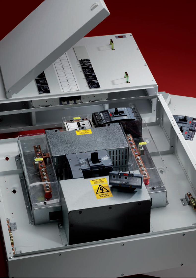
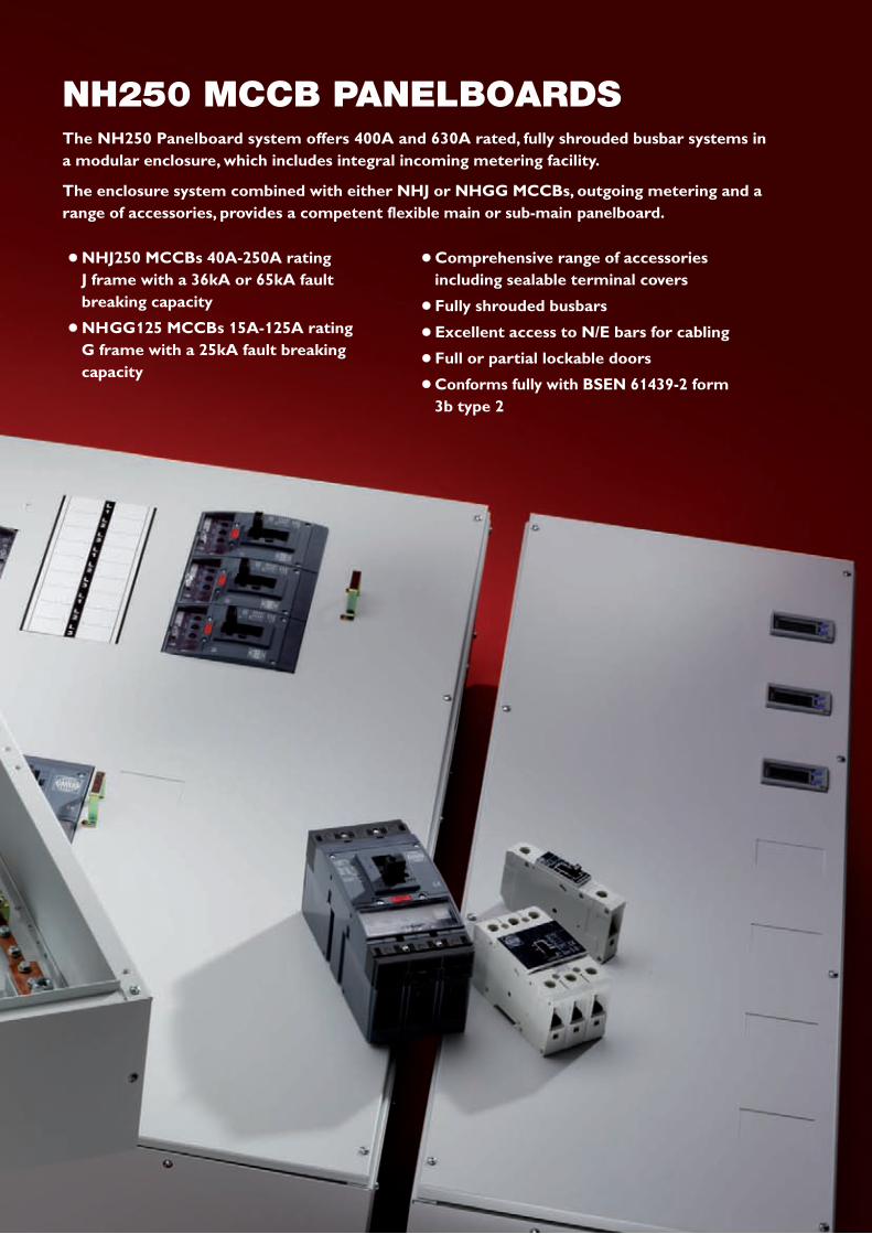
The NH250 Panelboard system offers 400A and 630A rated, fully shrouded busbar systems ina modular enclosure, which includes integral incoming metering facility.
The enclosure system combined with either NHJ or NHGG MCCBs, outgoing metering and arange of accessories, provides a competent flexible main or sub-main panelboard.
NH250 MCCB PANELBOARDS
l NHJ250 MCCBs 40A-250A rating J frame with a 36kA or 65kA faultbreaking capacity
l NHGG125 MCCBs 15A-125A rating G frame with a 25kA fault breakingcapacity
l Comprehensive range of accessoriesincluding sealable terminal covers
l Fully shrouded busbars
l Excellent access to N/E bars for cabling
l Full or partial lockable doors
l Conforms fully with BSEN 61439-2 form3b type 2

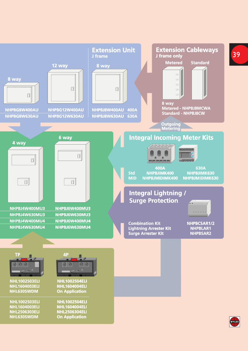
Panelboards(includes TP or 4P switching unit)
TP4P
400A NHPBJ2W400MU3 NHPBJ4W400MU3 NHPBJ6W400MU3
630A NHPBJ2W630MU3 NHPBJ4W630MU3 NHPBJ6W630MU3
400A NHPBJ2W400MU4 NHPBJ4W400MU4 NHPBJ6W400MU4
630A NHPBJ2W630MU4 NHPBJ4W630MU4 NHPBJ6W630MU4
2 way
4 way6 way
Extension UnitsG frame
Extension UnitJ frame
Panelboard Cableways Integral Incoming Meter Kits
2 way
4 way6 way
2 way
4 way6 way
Metered2 way - NHPBJ2MCW4 way - NHPBJ4MCW 6 way - NHPBJ6MCW
Standard2 way - NHPBJ2CW4 way - NHPBJ4CW 6 way - NHPBJ6CW
Extension CablewaysG frame
4 way
8 way
12 way
4 way
8 way
12 way
Metered4 way - NHPBG4MCWA8 way - NHPBG8MCWA 12 way - NHPBG12MCWA
Standard4 way - NHPBG4CW8 way - NHPBG8CW 12 way - NHPBG12CW
400A NHPBG4W400AU NHPBG8W400AU NHPBG12W400AU
630A NHPBG4W630AU NHPBG8W630AU NHPBG12W630AU
NHPBJ8W400AU 400A
NHPBJ8W630AU 630A
4 way
8 way
8 way12 way
Extension CablewaysJ frame only
StandardMetered
8 way Metered - NHPBJ8MCWAStandard - NHPBJ8CW
400A 630AStd NHPBJIMK400 NHPBJIMK630MID NHPBJMIDIMK400 NHPBJMIDIMK630
Outgoing Metering
Standard MID63A G frame Meter Kit NHPBJOMK63 -125A G frame Meter Kit NHPBJOMK125 NHPBJMIDOMK125160A J frame Meter Kit NHPBJOMK160 NHPBJMIDOMK160250A J frame Meter Kit NHPBJOMK250 NHPBJMIDOMK250
Each metering cableway of outgoing meter kits requires powersupply cable NHPBOCL
OutgoingMetering
OutgoingMetering
CA
RLO
GA
VA
ZZI
kWh
M21
CA
RLO
GA
VA
ZZI
kWh
M21
Integral Lightning / Surge Protection
Combination Kit NHPBCSAR1/2Lightning Arrester Kit NHPBLAR1Surge Arrester Kit NHPBSAR2
OvercurrentRelease Modules(required for each incomer)
160A - 400A NHL1604003ELI NHL1604004ELI100A - 250A NHL1002503ELI NHL1002504ELI
Switch Disconnector NHL630SWDM On Application
TP 4P
40
0A
160A - 400A NHL1604003ELI NHL1604004ELI100A - 250A NHL1002503ELI NHL1002504ELI
250A - 630A NHL2506303ELI NHL2506304ELISwitch Disconnector NHL630SWDM On Application6
30
A
Extension Units rating must match the rating of the Panelboard being extended.
G frameExtension Cableways
4 way
Extension Cableways12 way
8 way
12 way
8 way
4 way
G frameExtension Units
d being extended.
12 way
Panelboarmatch the rating of the Extension Units rating must
Extension Units
8 way
4 way
d being extended. match the rating of the Extension Units rating must
12 way
8 way
J frameExtension Unit
12 way 8 way
Extension UnitJ frame onlyExtension Cableways
J frame onlyExtension Cableways
edMeter dStandar
Extension Cableways
Panelboar
12 way - NHPBG12MCW8 way - NHPBG8MCW4 way - NHPBG4MCW
edMeter
d CablewaysPanelboar6 way
A 12 way - NHPBG12MCW12 way - NHPBG12MCWA A
Metering
8 way - NHPBG8MCW8 way - NHPBG8MCWA A4 way - NHPBG4MCW4 way - NHPBG4MCWA
Outgoing
6 way
12 way - NHPBG12CW 8 way - NHPBG8CW 4 way - NHPBG4CW
dStandar
630A
(includes TP or 4P Panelboar
6 way
400A
NHPBG8W630AU
(includes TP or 4P dsPanelboar
NHPBG4W630AU
NHPBG8W400AU NHPBG4W400AU
NHPBG12W630AU
6 way4 way
NHPBG8W630AU
NHPBG12W400AU NHPBG8W400AU
NHPBJ8W630AU
6 way
NHPBJ8W400AU
NHPBG12W630AU
NHPBG12W400AU
630A
Integral Incoming Meter Kits
NHPBJ8W630AU
400ANHPBJ8W400AU
Outgoing
Integral Incoming Meter Kits
d - NHPBJ8CW StandarMeter8 way
MeteringOutgoing
Integral Incoming Meter Kits
2 way
6 way4 way
4 way
2 way
switching unit)6 way
switching unit)2 way
NHPBJMIDIMK400 MID NHPBJIMK400 Std
400A
Integral Lightning /
NHPBJMIDIMK630NHPBJMIDIMK400 NHPBJIMK630NHPBJIMK400
630A400A
M21
AZZI
kWhVC
AR
LO G
A
Integral Lightning /
NHPBJMIDIMK630NHPBJIMK630
6 way - NHPBJ6MCW 4 way - NHPBJ4MCW 2 way - NHPBJ2MCW
edMeter
6 way - NHPBJ6MCW 4 way - NHPBJ4MCW 2 way - NHPBJ2MCW
6 way - NHPBJ6CW 4 way - NHPBJ4CW 2 way - NHPBJ2CW
dStandar
4PTP
630A
400A
630A
400A
NHPBJ2W630MU4
NHPBJ2W400MU4
NHPBJ2W630MU3
NHPBJ2W400MU3
NHPBJ6W630MU4 NHPBJ4W630MU4
NHPBJ6W400MU4 NHPBJ4W400MU4
NHPBJ6W630MU3 NHPBJ4W630MU3
NHPBJ6W400MU3 NHPBJ4W400MU3
NHPBJ6W630MU4
NHPBJ6W400MU4
NHPBJ6W630MU3
NHPBJ6W400MU3
ester Kit Surge Arrester Kit Lightning Arr
Combination Kit
otectionSurge Pr
NHPBSAR2ester Kit NHPBLAR1ester Kit
NHPBCSAR1/2
otection
NHPBCSAR1/2
160A J frame Meter Kit 125A G frame Meter Kit 63A G frame Meter Kit
Outgoing Metering
NHPBJOMK160 160A J frame Meter Kit NHPBJOMK125 125A G frame Meter Kit NHPBJOMK63 63A G frame Meter Kit
Standar
Outgoing Metering
NHPBJMIDOMK160NHPBJOMK160 NHPBJMIDOMK125NHPBJOMK125
-NHPBJOMK63 MIDd Standar
M21
AZZI
kWhVC
AR
LO G
A
NHPBJMIDOMK160NHPBJMIDOMK125
ed for each incomer)equir(rRelease Modules
entcurrOver
Switch Disconnector
100A - 250A 160A - 400A
40
0A
ed for each incomer)Release Modules
ent
Switch Disconnector
100A - 250A 160A - 400A
On ApplicationNHL630SWDM
NHL1002504ELI NHL1002503ELI NHL1604004ELINHL1604003ELI
TP
On Application
NHL1002504ELI NHL1604004ELI
4P
supply cable NHPBOCLEach metering cableway of outgoing meter kits r
250A J frame Meter Kit 160A J frame Meter Kit
supply cable NHPBOCLEach metering cableway of outgoing meter kits r
NHPBJOMK250 250A J frame Meter Kit NHPBJOMK160 160A J frame Meter Kit
es powerequirEach metering cableway of outgoing meter kits r
NHPBJMIDOMK250NHPBJOMK250 NHPBJMIDOMK160NHPBJOMK160
NHPBJMIDOMK250NHPBJMIDOMK160
63
0A
Switch Disconnector 250A - 630A
100A - 250A 160A - 400A
Switch Disconnector 250A - 630A
100A - 250A 160A - 400A
On ApplicationNHL630SWDM NHL2506304ELINHL2506303ELI
NHL1002504ELI NHL1002503ELI NHL1604004ELINHL1604003ELI
On ApplicationNHL2506304ELI
NHL1002504ELI NHL1604004ELI
NH250 PANELBOARD SELECTION GUIDE
38
Panelboards(includes TP or 4P switching unit)
TP4P
400A NHPBJ2W400MU3 NHPBJ4W400MU3 NHPBJ6W400MU3
630A NHPBJ2W630MU3 NHPBJ4W630MU3 NHPBJ6W630MU3
400A NHPBJ2W400MU4 NHPBJ4W400MU4 NHPBJ6W400MU4
630A NHPBJ2W630MU4 NHPBJ4W630MU4 NHPBJ6W630MU4
2 way
4 way6 way
Extension UnitsG frame
Extension UnitJ frame
Panelboard Cableways Integral Incoming Meter Kits
2 way
4 way6 way
2 way
4 way6 way
Metered2 way - NHPBJ2MCW4 way - NHPBJ4MCW 6 way - NHPBJ6MCW
Standard2 way - NHPBJ2CW4 way - NHPBJ4CW 6 way - NHPBJ6CW
Extension CablewaysG frame
4 way
8 way
12 way
4 way
8 way
12 way
Metered4 way - NHPBG4MCWA8 way - NHPBG8MCWA 12 way - NHPBG12MCWA
Standard4 way - NHPBG4CW8 way - NHPBG8CW 12 way - NHPBG12CW
400A NHPBG4W400AU NHPBG8W400AU NHPBG12W400AU
630A NHPBG4W630AU NHPBG8W630AU NHPBG12W630AU
NHPBJ8W400AU 400A
NHPBJ8W630AU 630A
4 way
8 way
8 way12 way
Extension CablewaysJ frame only
StandardMetered
8 way Metered - NHPBJ8MCWAStandard - NHPBJ8CW
400A 630AStd NHPBJIMK400 NHPBJIMK630MID NHPBJMIDIMK400 NHPBJMIDIMK630
Outgoing Metering
Standard MID63A G frame Meter Kit NHPBJOMK63 -125A G frame Meter Kit NHPBJOMK125 NHPBJMIDOMK125160A J frame Meter Kit NHPBJOMK160 NHPBJMIDOMK160250A J frame Meter Kit NHPBJOMK250 NHPBJMIDOMK250
Each metering cableway of outgoing meter kits requires powersupply cable NHPBOCL
OutgoingMetering
OutgoingMetering
CA
RLO
GA
VA
ZZI
kWh
M21
CA
RLO
GA
VA
ZZI
kWh
M21
Integral Lightning / Surge Protection
Combination Kit NHPBCSAR1/2Lightning Arrester Kit NHPBLAR1Surge Arrester Kit NHPBSAR2
OvercurrentRelease Modules(required for each incomer)
160A - 400A NHL1604003ELI NHL1604004ELI100A - 250A NHL1002503ELI NHL1002504ELI
Switch Disconnector NHL630SWDM On Application
TP 4P
40
0A
160A - 400A NHL1604003ELI NHL1604004ELI100A - 250A NHL1002503ELI NHL1002504ELI
250A - 630A NHL2506303ELI NHL2506304ELISwitch Disconnector NHL630SWDM On Application6
30
A
Extension Units rating must match the rating of the Panelboard being extended.
G frameExtension Cableways
4 way
Extension Cableways12 way
8 way
12 way
8 way
4 way
G frameExtension Units
d being extended.
12 way
Panelboarmatch the rating of the Extension Units rating must
Extension Units
8 way
4 way
d being extended. match the rating of the Extension Units rating must
12 way
8 way
J frameExtension Unit
12 way 8 way
Extension UnitJ frame onlyExtension Cableways
J frame onlyExtension Cableways
edMeter dStandar
Extension Cableways
Panelboar
12 way - NHPBG12MCW8 way - NHPBG8MCW4 way - NHPBG4MCW
edMeter
d CablewaysPanelboar6 way
MeteringOutgoing
6 way
12 way - NHPBG12CW 8 way - NHPBG8CW 4 way - NHPBG4CW
dStandar
630A
(includes TP or 4P Panelboar
6 way
400A
NHPBG8W630AU
(includes TP or 4P dsPanelboar
NHPBG4W630AU
NHPBG8W400AU NHPBG4W400AU
NHPBG12W630AU
6 way4 way
NHPBG8W630AU
NHPBG12W400AU NHPBG8W400AU
NHPBJ8W630AU
6 way
NHPBJ8W400AU
NHPBG12W630AU
NHPBG12W400AU
630A
Integral Incoming Meter Kits
NHPBJ8W630AU
400ANHPBJ8W400AU
Outgoing
Integral Incoming Meter Kits
d - NHPBJ8CW StandarAed - NHPBJ8MCWed - NHPBJ8MCWAMeter
8 way
MeteringOutgoing
Integral Incoming Meter Kits
2 way
6 way4 way
4 way
2 way
switching unit)6 way
switching unit)2 way
NHPBJMIDIMK400 MID NHPBJIMK400 Std
400A
Integral Lightning /
NHPBJMIDIMK630NHPBJMIDIMK400 NHPBJIMK630NHPBJIMK400
630A400A
M21
AZZI
kWhVC
AR
LO G
A
Integral Lightning /
NHPBJMIDIMK630NHPBJIMK630
6 way - NHPBJ6MCW 4 way - NHPBJ4MCW 2 way - NHPBJ2MCW
edMeter
6 way - NHPBJ6MCW 4 way - NHPBJ4MCW 2 way - NHPBJ2MCW
6 way - NHPBJ6CW 4 way - NHPBJ4CW 2 way - NHPBJ2CW
dStandar
4PTP
630A
400A
630A
400A
NHPBJ2W630MU4
NHPBJ2W400MU4
NHPBJ2W630MU3
NHPBJ2W400MU3
NHPBJ6W630MU4 NHPBJ4W630MU4
NHPBJ6W400MU4 NHPBJ4W400MU4
NHPBJ6W630MU3 NHPBJ4W630MU3
NHPBJ6W400MU3 NHPBJ4W400MU3
NHPBJ6W630MU4
NHPBJ6W400MU4
NHPBJ6W630MU3
NHPBJ6W400MU3
ester Kit Surge Arrester Kit Lightning Arr
Combination Kit
otectionSurge Pr
NHPBSAR2ester Kit NHPBLAR1ester Kit
NHPBCSAR1/2
otection
NHPBCSAR1/2
160A J frame Meter Kit 125A G frame Meter Kit 63A G frame Meter Kit
Outgoing Metering
NHPBJOMK160 160A J frame Meter Kit NHPBJOMK125 125A G frame Meter Kit NHPBJOMK63 63A G frame Meter Kit
Standar
Outgoing Metering
NHPBJMIDOMK160NHPBJOMK160 NHPBJMIDOMK125NHPBJOMK125
-NHPBJOMK63 MIDd Standar
M21
AZZI
kWhVC
AR
LO G
A
NHPBJMIDOMK160NHPBJMIDOMK125
ed for each incomer)equir(rRelease Modules
entcurrOver
Switch Disconnector
100A - 250A 160A - 400A
40
0A
ed for each incomer)Release Modules
ent
Switch Disconnector
100A - 250A 160A - 400A
On ApplicationNHL630SWDM
NHL1002504ELI NHL1002503ELI NHL1604004ELINHL1604003ELI
TP
On Application
NHL1002504ELI NHL1604004ELI
4P
supply cable NHPBOCLEach metering cableway of outgoing meter kits r
250A J frame Meter Kit 160A J frame Meter Kit
supply cable NHPBOCLEach metering cableway of outgoing meter kits r
NHPBJOMK250 250A J frame Meter Kit NHPBJOMK160 160A J frame Meter Kit
es powerequirEach metering cableway of outgoing meter kits r
NHPBJMIDOMK250NHPBJOMK250 NHPBJMIDOMK160NHPBJOMK160
NHPBJMIDOMK250NHPBJMIDOMK160
63
0A
Switch Disconnector 250A - 630A
100A - 250A 160A - 400A
Switch Disconnector 250A - 630A
100A - 250A 160A - 400A
On ApplicationNHL630SWDM NHL2506304ELINHL2506303ELI
NHL1002504ELI NHL1002503ELI NHL1604004ELINHL1604003ELI
On ApplicationNHL2506304ELI
NHL1002504ELI NHL1604004ELI
39
40
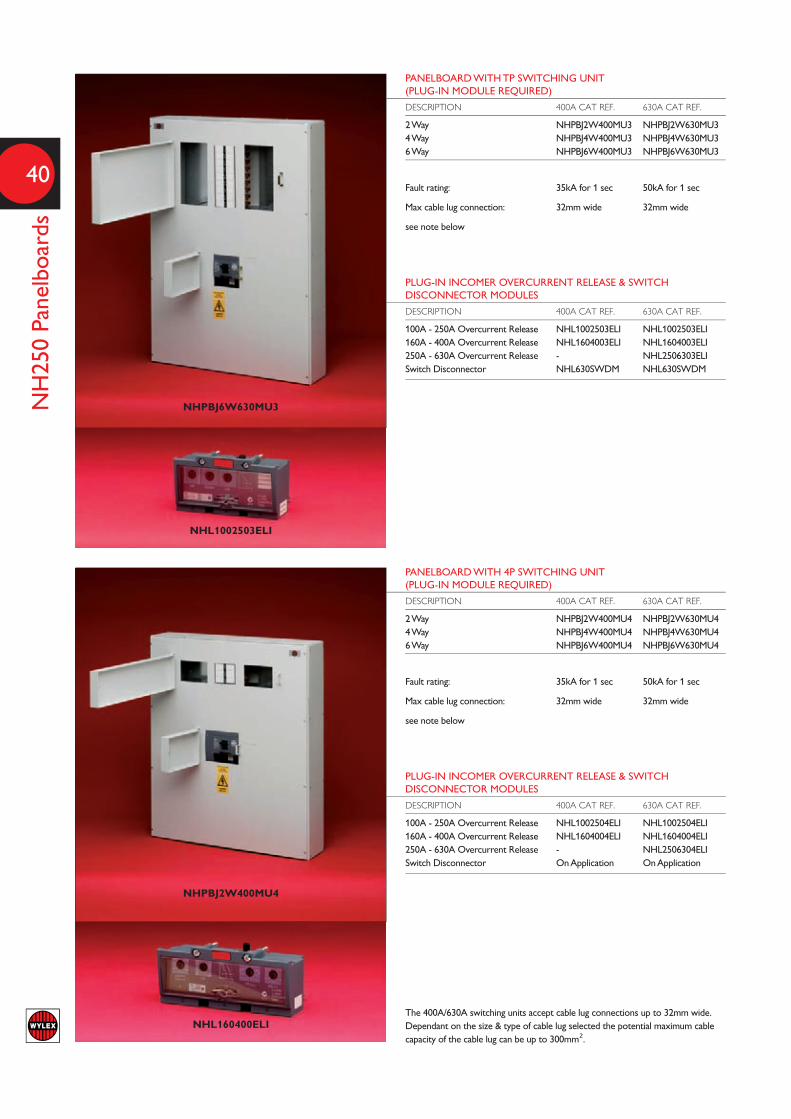
PANELBOARD WITH TP SWITCHING UNIT(PLUG-IN MODULE REQUIRED)
DESCRIPTION 400A CAT REF. 630A CAT REF.
2 Way NHPBJ2W400MU3 NHPBJ2W630MU34 Way NHPBJ4W400MU3 NHPBJ4W630MU36 Way NHPBJ6W400MU3 NHPBJ6W630MU3
Fault rating: 35kA for 1 sec 50kA for 1 sec
Max cable lug connection: 32mm wide 32mm wide
see note below
PLUG-IN INCOMER OVERCURRENT RELEASE & SWITCHDISCONNECTOR MODULES
DESCRIPTION 400A CAT REF. 630A CAT REF.
100A - 250A Overcurrent Release NHL1002503ELI NHL1002503ELI160A - 400A Overcurrent Release NHL1604003ELI NHL1604003ELI250A - 630A Overcurrent Release - NHL2506303ELISwitch Disconnector NHL630SWDM NHL630SWDM
PANELBOARD WITH 4P SWITCHING UNIT(PLUG-IN MODULE REQUIRED)
DESCRIPTION 400A CAT REF. 630A CAT REF.
2 Way NHPBJ2W400MU4 NHPBJ2W630MU44 Way NHPBJ4W400MU4 NHPBJ4W630MU46 Way NHPBJ6W400MU4 NHPBJ6W630MU4
Fault rating: 35kA for 1 sec 50kA for 1 sec
Max cable lug connection: 32mm wide 32mm wide
see note below
PLUG-IN INCOMER OVERCURRENT RELEASE & SWITCHDISCONNECTOR MODULES
DESCRIPTION 400A CAT REF. 630A CAT REF.
100A - 250A Overcurrent Release NHL1002504ELI NHL1002504ELI160A - 400A Overcurrent Release NHL1604004ELI NHL1604004ELI250A - 630A Overcurrent Release - NHL2506304ELISwitch Disconnector On Application On Application
NHPBJ6W630MU3
NHPBJ2W400MU4
NHL1002503ELI
NH250 Panelboards
NHL160400ELIThe 400A/630A switching units accept cable lug connections up to 32mm wide.Dependant on the size & type of cable lug selected the potential maximum cablecapacity of the cable lug can be up to 300mm².

41
NH250 Panelboard M
eter & Surge A
rrester Kits
INTEGRAL LIGHTNING & SURGE ARRESTERS
CAT REF. DESCRIPTION
NHPBCSAR1/2 Combination Lightning & Surge Arrester KitNHPBLAR1 Lightning Arrester Kit (Type 1)NHPBSAR2 Surge Arrester Kit (Type 2)
Each kit contains: Lightning, Surge or Combination arrester, MCCB, mounting plate& cable loom. Supplied loose for assembly and connection by others.
Only one of these three options is possible per panelboard. MCCB mounted inbottom left hand NHJ position.
OUTGOING METER KITS*
STANDARD MID CAT REF. CAT REF. DESCRIPTION
NHPBJOMK63 - 63A Energy Meter Kit - G frameNHPBJOMK125 NHPBJMIDOMK125 125A Energy Meter Kit - G frameNHPBJOMK160 NHPBJMIDOMK160 160A Energy Meter Kit - J frameNHPBJOMK250 NHPBJMIDOMK250 250A Energy Meter Kit - J frame
Each kit contains: Digital meter offering Amps, Volts, kWh readout plus pulsedoutput, block current transformer (MID option - 3 separate CTs), fuses, mountingplates & cable looms. Supplied loose for assembly and connection by others.
* Each metering cableway of outgoing meter kits requires:NHPBOCL Meter Kit Voltage Supply Cable Loom
Current transformer internal dimensionsStandard versions: MID versions:63A & 125A - 16mm W x 31mm H slot 125A & 160A - 21mm diameter160A & 250A - 21mm W x 25mm H slot 250A - 28mm diameter
NHPBSAR2
NHPBJOMK250
INTEGRAL INCOMING METER KITS
400A CAT REF. 630A CAT REF. DESCRIPTION
NHPBJIMK400 NHPBJIMK630 Energy Meter Kit - StandardNHPBJMIDIMK400 NHPBJMIDIMK630 Energy Meter Kit - MID
Each kit contains: Digital meter offering Amps, Volts, kWh readout plus pulsedoutput, block current transformer, fuses, mounting plates & cable looms. Suppliedloose for assembly and connection by others.
Cable Connection Information:30mm x 10mm copper bar - M10 connection
NHPBJIMK400
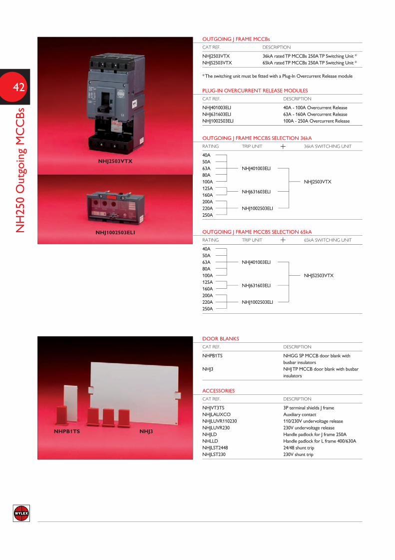
42
OUTGOING J FRAME MCCBs
CAT REF. DESCRIPTION
NHJ2503VTX 36kA rated TP MCCBs 250A TP Switching Unit *NHJS2503VTX 65kA rated TP MCCBs 250A TP Switching Unit *
* The switching unit must be fitted with a Plug-In Overcurrent Release module
PLUG-IN OVERCURRENT RELEASE MODULES
CAT REF. DESCRIPTION
NHJ401003ELI 40A - 100A Overcurrent ReleaseNHJ631603ELI 63A - 160A Overcurrent ReleaseNHJ1002503ELI 100A - 250A Overcurrent Release
OUTGOING J FRAME MCCBS SELECTION 36kA
RATING TRIP UNIT 36kA SWITCHING UNIT
40A50A63A NHJ401003ELI80A100A NHJ2503VTX125A
NHJ631603ELI160A200A220A NHJ1002503ELI250A
DOOR BLANKS
CAT REF. DESCRIPTION
NHPB1TS NHGG SP MCCB door blank withbusbar insulators
NHJ3 NHJ TP MCCB door blank with busbarinsulators
ACCESSORIES
CAT REF. DESCRIPTION
NHJVT3TS 3P terminal shields J frameNHJLAUXCO Auxiliary contactNHJLUVR110230 110/230V undervoltage release NHJLUVR230 230V undervoltage release NHJLD Handle padlock for J frame 250ANHLLD Handle padlock for L frame 400/630ANHJLST2448 24/48 shunt tripNHJLST230 230V shunt trip
NHPB1TS NHJ3
NH250 Outgoing MCCBs
OUTGOING J FRAME MCCBS SELECTION 65kA
RATING TRIP UNIT 65kA SWITCHING UNIT
40A50A63A NHJ401003ELI80A100A NHJS2503VTX125A
NHJ631603ELI160A200A220A NHJ1002503ELI250A
NHJ1002503ELI
NHJ2503VTX
+
+
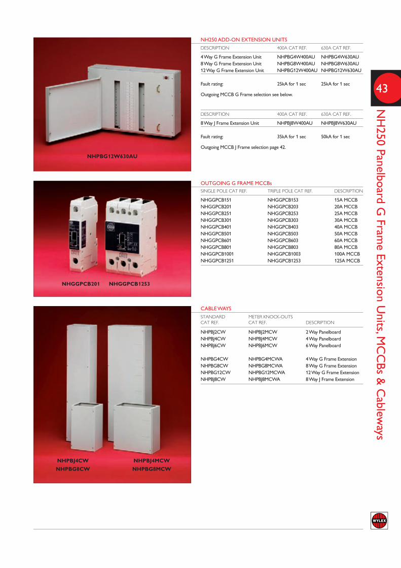
43
NH250 Panelboard G
Frame Extension U
nits, MCCBs &
Cablew
ays
NH250 ADD-ON EXTENSION UNITS
DESCRIPTION 400A CAT REF. 630A CAT REF.
4 Way G Frame Extension Unit NHPBG4W400AU NHPBG4W630AU8 Way G Frame Extension Unit NHPBG8W400AU NHPBG8W630AU12 Way G Frame Extension Unit NHPBG12W400AU NHPBG12W630AU
Fault rating: 25kA for 1 sec 25kA for 1 sec
Outgoing MCCB G Frame selection see below.
DESCRIPTION 400A CAT REF. 630A CAT REF.
8 Way J Frame Extension Unit NHPBJ8W400AU NHPBJ8W630AU
Fault rating: 35kA for 1 sec 50kA for 1 sec
Outgoing MCCB J Frame selection page 42.
CABLE WAYS
STANDARD METER KNOCK-OUTS CAT REF. CAT REF. DESCRIPTION
NHPBJ2CW NHPBJ2MCW 2 Way PanelboardNHPBJ4CW NHPBJ4MCW 4 Way PanelboardNHPBJ6CW NHPBJ6MCW 6 Way Panelboard
NHPBG4CW NHPBG4MCWA 4 Way G Frame ExtensionNHPBG8CW NHPBG8MCWA 8 Way G Frame ExtensionNHPBG12CW NHPBG12MCWA 12 Way G Frame ExtensionNHPBJ8CW NHPBJ8MCWA 8 Way J Frame Extension
NHPBG12W630AU
NHPBJ4CW
NHPBG8CW
NHPBJ4MCW
NHPBG8MCW
OUTGOING G FRAME MCCBsSINGLE POLE CAT REF. TRIPLE POLE CAT REF. DESCRIPTION
NHGGPCB151 NHGGPCB153 15A MCCBNHGGPCB201 NHGGPCB203 20A MCCBNHGGPCB251 NHGGPCB253 25A MCCBNHGGPCB301 NHGGPCB303 30A MCCBNHGGPCB401 NHGGPCB403 40A MCCBNHGGPCB501 NHGGPCB503 50A MCCBNHGGPCB601 NHGGPCB603 60A MCCBNHGGPCB801 NHGGPCB803 80A MCCBNHGGPCB1001 NHGGPCB1003 100A MCCBNHGGPCB1251 NHGGPCB1253 125A MCCB
NHGGPCB201 NHGGPCB1253

l Robust steel enclosures with cable glandingplate supplied top and bottom
l Removable door opens through 180º forease of access
l Easy access fuse link fixingsl Neutral fully ratedl Fully shrouded terminalsl Handle padlocking facility locks switch &
door in off position l Large cable terminal capacityl Ingress protection to IP4Xl Positive indication of On and Off
NH Fuse combination units are designedwith features that ensure compliance withEN60947 while also providing an economicaland high quality range of industrial switchgearproducts.
With ratings from 20A to 200A and a choiceof single pole or three pole configurations,NH fuse combination units have a utilisationcategory of AC23A, and fused short circuitcapacity of 80kA.
NH FUSE-COMBINATION UNITS

45
NH Fuse C
ombination U
nits & Isolator Sw
itches
NHSPSF32
NHTPSF63
NHTPSF160
NH FUSE COMBINATION UNIT 20A-32A
SUPPLIED CAT REF. AMPERAGE MODULES TYPE WITH FUSES
NHSPSF20 20A 4 SP & N YESNHTPSF20 20A 4 TP & N YESNHSPSF32 32A 4 SP & N YESNHTPSF32 32A 4 TP & N YES
Fuse Combination Units Technical Specification EN 60947-3 IEC 947-380kA RMS Fused Short Circuit Capacity 415V ac Rated Voltage Full Uninterrupted DutyAC23A Utilisation Category
NH FUSE COMBINATION UNIT 63A-125A
SUPPLIEDCAT REF. AMPERAGE MODULES TYPE WITH FUSES
NHSPSF63 63A 5 SP & N YESNHTPSF63 63A 5 TP & N YESNHSPSF100 100A 5 SP & N YESNHTPSF100 100A 5 TP & N YESNHTPSF125 125A 6 TP & N YES
ACCESSORIES
CAT REF. DESCRIPTION
NHCIL2 63A Copper Isolator linksNHCIL3 100A to 200A Copper Isolator linksNHCSB2 63A to 100A Cable Spreader BoxNHCSB3 125A Cable Spreader BoxFor fuse types see page 50
NH FUSE COMBINATION UNIT 160A-800A
SUPPLIEDCAT REF. AMPERAGE MODULES TYPE WITH FUSES
NHTPSF160 160A 6 TP & N NONHTPSF200 200A 6 TP & N NONHTPSF315 315A 8 TP & N NONHTPSF400 400A 8 TP & N NONHTPSF630 630A 12 TP & N NONHTPSF800 800A 12 TP & N NO
ACCESSORIES
CAT REF. DESCRIPTION
NHCIL3 100A to 200A Copper Isolator links NHCSB3 125A to 200A Cable Spreader Box NHCIL4 315A & 400A Copper Isolator links NHCSB4 315A & 400A Cable Spreader Box NHCIL5 630A & 800A Copper Isolator links NHCSB5 630A & 800A Cable Spreader Box
For fuse types see page 50
BUS BAR CHAMBER
CAT REF. AMPERAGE MODULES TYPE
NHSFBBC400 400A 16 TP & NNHSFBBTM250 250A Each Busbar Terminal
Cable spreading room is allowed for at one end only. To fit a 4 core cable atboth ends an additional cable spreader box will be required.
160CM 110M
METAL-SWITCH FUSE
CAT REF. CURRENT RATING NO. OF WAYS
106 45A 1106RED 45A 1108M 60A 1160CM* 60A 1110M/63* 63A 1110M/80* 80A 1110M* 100A 1
*Supplied complete with cartridge fuse
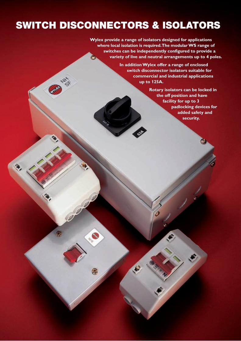
Wylex provide a range of isolators designed for applicationswhere local isolation is required. The modular WS range of
switches can be independently configured to provide a variety of live and neutral arrangements up to 4 poles.
In addition Wylex offer a range of enclosed switch disconnector isolators suitable for
commercial and industrial applicationsup to 125A.
Rotary isolators can be locked in the off position and have
facility for up to 3 padlocking devices for
added safety and security.
SWITCH DISCONNECTORS & ISOLATORS

47
Isolators & Switch D
isconnectors
921E
WS102 WS104
TRIPLE POLE & NEUTRAL 415V, 50HZ AC
CAT REF. DESCRIPTION CURRENT RATING
921E With switched neutral, surface mounting in a metal enclosure 32A921X With switched neutral, for loose mounting in an enclosure (Non DIN) 32A
WS RANGE OF MODULAR ISOLATORS
CAT REF. DESCRIPTION CURRENT RATING
WS601 1 Pole, 1 module 63AWS101 1 Pole, 1 module 100AWS121 1 Pole, 1 module 125A
WS602 2 Pole, 2 module 63AWS102 2 Pole, 2 module 100AWS122 2 Pole, 2 module 125A
WS603 3 Pole, 3 module 63AWS103 3 Pole, 3 module 100AWS123 3 Pole, 3 module 125A
WS604 4 Pole, 4 module 63AWS104 4 Pole, 4 module 100AWS124 4 Pole, 4 module 125A
NH ISOLATOR SWITCHES STEEL ENCLOSURE
TP&N/SP&N RATING BOX SIZE
NHSW320 20A 1NHSW332 32A 1NHSW340 40A 1NHSW363 63A 1NHSW363X 63A 2NHSW3100 100A 2NHSW3125 125A 2
NHSW363X
SUPPLY AUTHORITY ISOLATOR ASSEMBLIES
CAT REF. DESCRIPTION CURRENT RATING
REC2S Slimline & DP Switch Enclosure 100AREC2 DP Isolator & 4 Mod Enclosure 100AREC3 TP Isolator & 4 Mod Enclosure 100AREC4 4P Isolator & 4 Mod Enclosure 100A
SUPPLY AUTHORITY TWIN TERMINAL ISOLATOR ASSEMBLIES
CAT REF. DESCRIPTION CURRENT RATING
REC2STT DP Isolator Hex Socket Screw & 2 Mod Enclosure 100ARECSW2S DP Isolator Combi Screw & 2 Mod Enclosure 100ARECSW3 TP Isolator Combi Screw & 4 Mod Enclosure 100ARECSW4 4P Isolator Combi Screw & 4 Mod Enclosure 100A
A wide range of custom built variations is also available. Contact WylexTechnical for full details.
REC2S REC4


Residual Current Devices are a critical device of the Solution17 offer thathelp installers meet the latest amendments of the wiring regulations,guarding circuits and offering additional 30mA personal protection againstelectric shock 24/7, 365 days of every year.
These loose RCDs and enclosures are ideal for installations with an existingconsumer unit that require an upgraded, additional or modified circuit thathas to comply to the latest wiring regulations; where 30mA additionalprotection is required for almost every new circuit which is beyond thelevels sensed by a traditional overcurrent device such as fuses or miniaturecircuit breakers installed in the existing consumer unit.
One of the largest ranges available in the UK todayoffers other features which include:-
l Fully shrouded terminals
l Contact position indication on the dolly handle
l Both AC and Type A (DCsensitive) devices available
l A range of enclosuresfrom IP20 up to IP65
l Time delay versionsavailable in 2 and 4
pole configurations
LIFELINE RANGE
EDITIONFor details on the application to meet the 17th editionwiring regulations please refer to page 59.
1st AMENDMENT

50
Lifeline Range
2 POLE RCDs – TYPE AC
CAT REF. RATED CURRENT SENSITIVITY
WRS16/2 16A 30mAWRS25/2 25A 30mAWRS32/2 32A 30mAWRS40/2 40A 30mAWRM40/2 40A 100mAWRS63/2 63A 30mAWRM63/2 63A 100mAWRL63/2 63A 300mAWRS80/2 80A 30mAWRM80/2 80A 100mAWRS100/2 100A 30mAWRM100/2 100A 100mAWRL100/2 100A 300mA
2 POLE RCDs DC SENSITIVE – TYPE A
CAT REF. RATED CURRENT SENSITIVITY
WRDVS32/2 32A 10mAWRDS40/2 40A 30mAWRDM40/2 40A 100mAWRDS63/2 63A 30mAWRDS80/2 80A 30mAWRDS100/2 100A 30mAWRDM100/2 100A 100mA
4 POLE RCDs – TYPE AC
CAT REF. RATED CURRENT SENSITIVITY
WRS32/4 32A 30mAWRS40/4 40A 30mAWRM40/4 40A 100mAWRS63/4 63A 30mAWRM63/4 63A 100mAWRL63/4 63A 300mAWRS100/4 100A 30mAWRM100/4 100A 100mAWRL100/4 100A 300mA
4 POLE RCDs DC SENSITIVE – TYPE A
CAT REF. RATED CURRENT SENSITIVITY
WRDS40/4 40A 30mAWRDM40/4 40A 100mAWRDS63/4 63A 30mAWRDM63/4 63A 100mAWRDS100/4 100A 30mAWRDM100/4 100A 100mA
TIME DELAY UNITS (100ms) TYPE S
CAT REF. DESCRIPTION RATED CURRENT SENSITIVITY
WRMT100/2 2P 100A 100mAWRMT100/4 4P 100A 100mA
TYPE B DC SENSITIVE RCD
CAT REF. DESCRIPTION
NSPE-5579 16A 30mA DP RCDNSPE-5580 40A 30mA DP RCDNSPE-5581 40A 300mA DP RCD
WRS32/2 WRS80/2
WRS100/2 WRM100/2
WRS63/4
NSBS RCBO (combined MCB/RCD device)
CURRENT RCDC CURVE RATING RATING POLES MODULES
WRCBX6C2 6A 30mA 2 2WRCBX10C2 10A 30mA 2 2WRCBX16C2 16A 30mA 2 2WRCBX20C2 20A 30mA 2 2WRCBX32C2 32A 30mA 2 2WRCBX40C2 40A 30mA 2 2
WRMT100/4
WRCBX16C2 WRCBX32C2

NH METAL DIN ENCLOSURES
CAT REF. DESCRIPTION
NH4ED6 4 modulesNH7ED6 7 modulesNH10ED6 10 modulesNH13ED6 13 modulesNH16ED6 16 modulesNH21ED6 21 modules
Supplied with earth & neutral terminal bars cover and visor
IP65 DIN ENCLOSURES AND ACCESSORIES
CAT REF. DESCRIPTION
WBE3 2/3 module enclosureWBE4 4 module enclosureWBE3/EK Earth blockWBE3/NK Neutral blockWBE4/EK Earth blockWBE4/NK Neutral blockWBE/BS Blanks
NH INSULATED DIN ENCLOSURES
CAT REF. DESCRIPTION
NH4ED4 4 modulesNH7ED4 7 modulesNH10ED4 10 modulesNH13ED4 13 modulesNH16ED4 16 modulesNH21ED4 21 modules
Supplied with earth & neutral terminal bars cover and visor
NH10ED4
WBE4/NK installed in WBE4
51
Enclosures Range
DIN ENCLOSURES
CAT REF. CAT REF. DIN IPINSULATED METAL MODULES RATING
ESE2 ESM6 2 IP40ESi2S - 2 IP40ESE2L* - 2 IP40- ESM7 2 IP54
ESE4 - 4 IP20ESi4 ESM8 4 IP40- ESM11 4 IP54- ESM13** 4 IP54
* Supplied with earth connection link ** Enclosure for larger cables
ESE2 ESE4 ESM6 ESM8
NH13ED6


The Wylex Standard range of consumer unitsremains one of the most widely used ranges indomestic circuit protection applications.
Originally designed with fuses in mind, standardconsumer units can easily be upgraded to currentstandards by using the plug in range of MCBs.
This time saving feature offers installers aneconomical alternative to full consumer unitreplacement.
The range also includes SP&N switch fuses up to100A allowing for submain circuit installation orsystem extensions/additions to be easily completed.
STANDARD RANGE
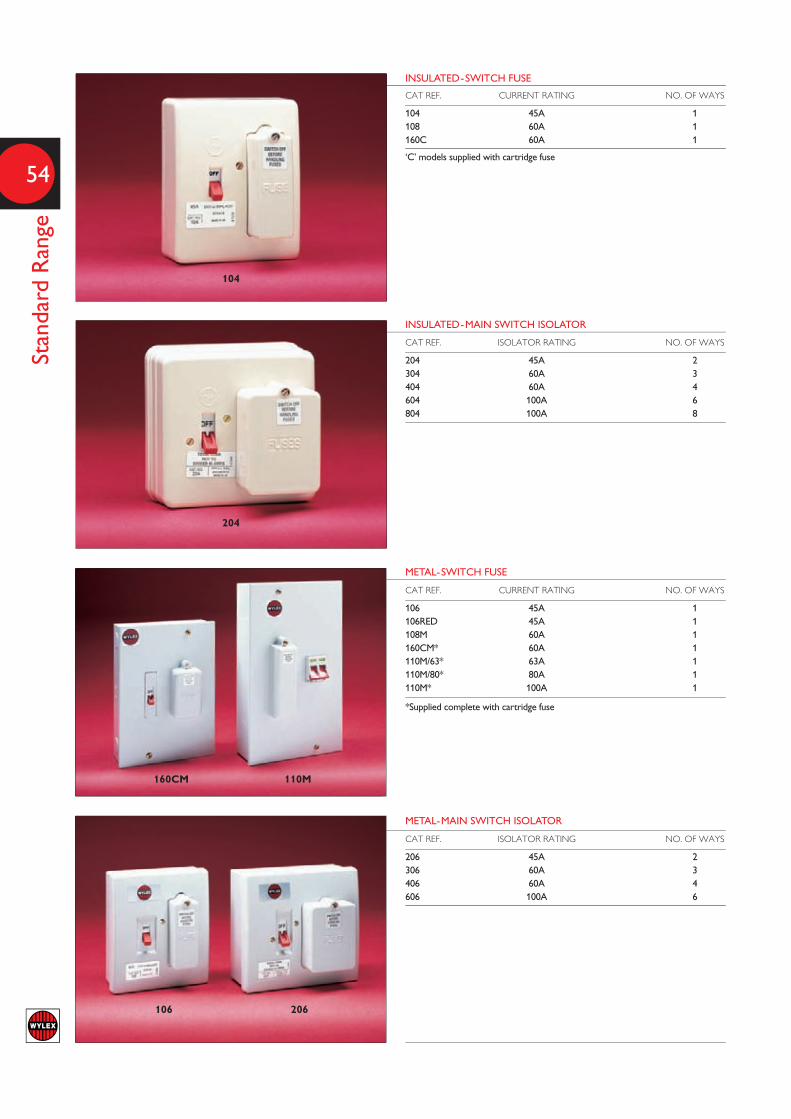
54
Standard Range
INSULATED-SWITCH FUSE
CAT REF. CURRENT RATING NO. OF WAYS
104 45A 1108 60A 1160C 60A 1
‘C’ models supplied with cartridge fuse
INSULATED-MAIN SWITCH ISOLATOR
CAT REF. ISOLATOR RATING NO. OF WAYS
204 45A 2304 60A 3404 60A 4604 100A 6804 100A 8
METAL-SWITCH FUSE
CAT REF. CURRENT RATING NO. OF WAYS
106 45A 1106RED 45A 1108M 60A 1160CM* 60A 1110M/63* 63A 1110M/80* 80A 1110M* 100A 1
*Supplied complete with cartridge fuse
METAL-MAIN SWITCH ISOLATOR
CAT REF. ISOLATOR RATING NO. OF WAYS
206 45A 2306 60A 3406 60A 4606 100A 6
104
204
160CM 110M
106 206

55
Standard Range O
utgoing Devices &
Accessories
MCBs
CAT REF. CURRENT RATING CONTACT SHIELD COLOUR
B6 6A WHITEB10 10A GREYB16 16A BLUEB20 20A YELLOWB32 32A REDB40 40A ORANGE
May be used as a direct replacement for rewirable fuses part ref R5, R15, R20and R30
CARTRIDGE FUSES (Including contact shield)
CAT REF. CURRENT RATING CONTACT SHIELD COLOUR
C5 5A WHITEC15 15A BLUEC20 20A YELLOWC30 30A REDC35 35A ORANGEC40 40A ORANGEC45 45A GREEN
CAT REF. CURRENT RATING
L45 45A L60 60A
May be used as a direct replacement for rewirable fuses part ref R5, R15, R20and R30
CARTRIDGE FUSE LINKS
CAT REF. CURRENT RATING CONTACT SHIELD COLOUR
CFL05 5A WHITECFL10 10A BLUECFL15 15A BLUECFL20 20A YELLOWCFL30 30A REDCFL35 35A ORANGECFL40 40A ORANGECFL45 45A GREEN
CARTRIDGE FUSE LINKS
CAT REF. CURRENT RATING
LFL45 45A LFL60 60A
LFL63 63A LFL80 80A LFL100 100A
ACCESSORIES
CAT REF. DESCRIPTION
FWC* Fusewire card 1m 5A, 15A, 30A M10 Blank shield for unused ways
* Rewirable fuses replaced by Bxx Plug in MCBs or Cxx Cartridge fuses above
B6 B10 B16 B20 B32 B40
C5 C15 C20 C30 C35 C40 C45
CARTRIDGE FUSE LINKS
M10
}
}
}
for use with 108, 145 & 160type switch fuses
for use with 108 or 108M
for use with 110Munits only

TECHNICAL DATA& DIMENSIONS
A C
B
D
E
Maximum prospective fault current
Healthy circuit current
Fault
20ms 20ms
A B
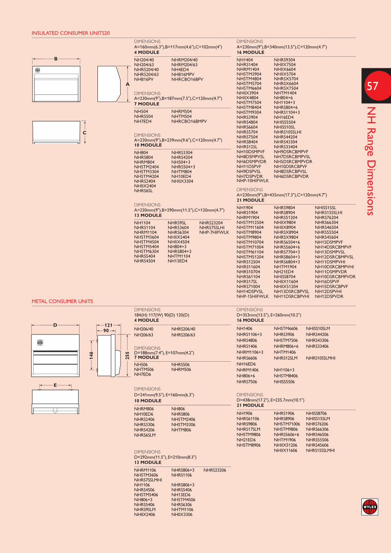
57
NH Range D
imensions
INSULATED CONSUMER UNITS20
B
A
C
D 12190
255
146
E
DIMENSIONSA=160mm(6.3"),B=117mm(4.6"),C=102mm(4")4 MODULE
NH204/40 NHRM204/40NH204/63 NHRM204/63NHRS204/40 NH4ED4NHRS204/63 NHB16MPVNHB16PV NHRCBO16BPV
DIMENSIONSA=230mm(9"),B=187mm(7.5"),C=120mm(4.7")7 MODULE
NH504 NHRM504NHRS504 NHTM504NH7ED4 NHRCBO16BMPV
DIMENSIONSA=230mm(9"),B=239mm(9.6"),C=120mm(4.7")10 MODULE
NH804 NHRS3304NHRS804 NHRS4204NHRM804 NH504+3NHSTM2404 NHRS504+3NHSTM3304 NHTM804NHSTM4204 NH10ED4NHRS2404 NHIIX3304NHIIX2404 NHRS6SL
DIMENSIONSA=230mm(9"),B=290mm(11.5"),C=120mm(4.7")13 MODULE
NH1104 NHRS9SL NHRS23204NHRS1104 NHRS3604 NHRS7SSLHINHRM1104 NHRS6304 NHP-7HIFWLKNHSTM3604 NHIIX5404NHSTM4504 NHIIX4504NHSTM5404 NH804+3NHSTM6304 NHRS804+3NHRS5404 NHTM1104NHRS4504 NH13ED4
DIMENSIONSA=230mm(9"),B=340mm(13.5"),C=120mm(4.7")16 MODULE
NH1404 NHRS9304 NHRS1404 NHIIX7504 NHRM1404 NHIIX6604 NHSTM3904 NHIIX5704 NHSTM4804 NHRSX5704NHSTM5704 NHRSX6604NHSTM6604 NHRSX7504NHIIX3904 NHTM1404NHIIX4804 NH804+6NHSTM7504 NH1104+3NHSTM8404 NHRS804+6NHSTM9304 NHRS1104+3NHRS3904 NH16ED4NHRS4804 NHISS5504NHRS6604 NHISS10SLNHRS5704 NHRS10SSLHINHRS7504 NHRS44204NHRS8404 NHRS43304NHRS12SL NHRS33404NH10DSMPVF NH9DSRCBMPVFNH8DSMPVSL NH7DSRCBMPVSLNH6DSMPVDR NH5DSRCBMPVDRNH11DSPVF NH10DSRCBPVFNH9DSPVSL NH8DSRCBPVSLNH7DSPVDR NH6DSRCBPVDRNHP-10HIFWLK
DIMENSIONSA=230mm(9"),B=435mm(17.3"),C=120mm(4.7")21 MODULE
NH1904 NHRS9804 NHISS15SLNHRS1904 NHRS8904 NHRS15SSLHINHRM1904 NHRS51204 NHRS76204NHSTM12504 NHIIX9804 NHRS66304NHSTM11604 NHIIX8904 NHRS46504NHSTM8904 NHRSX8904 NHRS55504NHSTM9804 NHRSX9804 NHRS45604NHSTM10704 NHRS6504+6 NH15DSMPVFNHSTM71004 NHRS5604+6 NH14DSRCBMPVFNHSTM61104 NHRS7704+3 NH13DSMPVSLNHSTM51204 NHRS8604+3 NH12DSRCBMPVSLNHRS12504 NHRS6804+3 NH11DSMPVHINHRS11604 NHTM1904 NH10DSRCBMPVHINHRS10704 NH21ED4 NH11DSMPVDRNHRS61104 NHISS8704 NH10DSRCBMPVDRNHRS17SL NHIIX11604 NH16DSPVFNHRS71004 NHIIX51204 NH15DSRCBPVFNH14DSPVSL NH13DSRCBPVSL NH12DSPVHINHP-15HIFWLK NH11DSRCBPVHI NH12DSPVDR
METAL CONSUMER UNITS
DIMENSIONS184(H) 117(W) 90(D) 120(D)4 MODULE
NH206/40 NHRS206/40NH206/63 NHRS206/63
DIMENSIONSD=188mm(7.4"), E=107mm(4.2")7 MODULE
NH506 NHRS506NHTM506 NHRM506NH7ED6
DIMENSIONSD=241mm(9.5"), E=160mm(6.3")10 MODULE
NHRM806 NH806NH10ED6 NHRS806NHRS2406 NHSTM2406NHRS3306 NHSTM3306NHRS4206 NHTM806NHRS6SLM
DIMENSIONSD=292mm(11.5"), E=210mm(8.3")13 MODULE
NHRM1106 NHRS806+3 NHRS23206NHSTM3606 NHRS1106 NHRS7SSLMHINH1106 NHRS806+3NHRS4506 NHRS5406NHSTM5406 NH13ED6NH806+3 NHSTM4506NHRS5406 NHRS6306NHRS9SLM NHTM1106NHIIX2406 NHIIX3306
DIMENSIONSD=353mm(13.5"), E=260mm(10.2")16 MODULE
NH1406 NHSTM6606 NHISS10SLMNHRS1106+3 NHRS3906 NHRS44206NHRS4806 NHSTM7506 NHRS43306NHRS1406 NHRM806+6 NHRS33406NHRM1106+3 NHTM1406 NHRS6606 NHRS12SLM NHRS10SSLMHINH16ED6NHRM1406 NH1106+3 NH806+6 NHSTM8406 NHRS7506 NHISS5506
DIMENSIONSD=438mm(17.2"), E=235.7mm(10.1")21 MODULE
NH1906 NHRS1906 NHISS8706NHRS61106 NHRS8906 NHISS15SLMNHRS9806 NHSTM71006 NHRS76206NHRS17SLM NHSTM9806 NHRS66306NHSTM9806 NHRS5606+6 NHRS46506NH21ED6 NHTM1906 NHRS55506NHSTM8906 NHIIX51206 NHRS45606 NHIIX11606 NHRS15SSLMHI
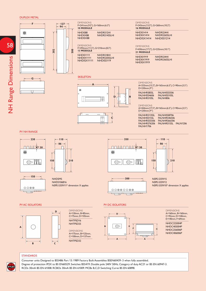
58
NH Range Dimensions
DUPLEX METAL
DIMENSIONSF=241mm(9.5"), G=160mm(6.3")10 MODULE
NHDIS88 NHDRS12HINHDIIX88 NHDRS14SSLHINHDISX88
DIMENSIONSF=292mm(11.5"), G=210mm(8.3")13 MODULE
NHDIS1111 NHDRS18HINHDIIX1111 NHDRS20SSLHINHDISX1111 NHDISS119
DIMENSIONSF=343mm(13.5"), G=260mm(10.2")16 MODULE
NHDIS1414 NHDRS24HINHDIIX1414 NHDRS26SSLHINHDISX1414 NHDISS1214
DIMENSIONSF=430mm(17.2"), G=235mm(10.1")21 MODULE
NHDIS1919 NHDRS34HINHDIIX1919 NHDRS36SSLHINHDISX1919
F
G
12794
500
302
STANDARDS
Consumer units Designed to BS5486 Part 13: 1989 Factory Built Assemblies BSEN60439-3 when fully assembled. Degree of protection IP2X to BS EN60529. Switches BS5419. Double pole 240V 50Hz. Category of duty AC21 or BS EN 60947-3.RCDs 30mA BS EN 61008. RCBOs 30mA BS EN 61009. MCBs B,C,D Switching Curve BS EN 60898.
150 210
150
230 110
86X* 30
150 210
300
350 110
86X* 30
150 210
150
230 110
86X* 30
150 210
300
350 110
86X* 30
DIMENSIONSA=333mm(13.2"), B=165mm(6.5"), C=90mm(3.5”)D=230mm(9”)
FALNHRS8SSL FALNHISS5506FALNHISS4606 FALNHISS10SLFALNHRS10SL FALNH806
DIMENSIONSA=444mm(17.5"), B=165mm(6.5"), C=90mm(3.5”)D=230mm(9”)
FALNHRS13SSL FALNHISS8706FALNHISS15SL FALNHRS46506FALNHRS55506 FALNHRS66306FALNHRS76206 FALNHRS15SL FALN1206FALNH1706
A
C
BD
SKELETON
PV NH RANGE
NHDSMSNHDS106B16NSPE-5359/11* dimension X applies
NSPE-5359/15NSPE-5359/12NSPE-5359/10* dimension X applies
DIMENSIONSA=130mm, B=85mm,C=75mm, D=105mm
NHTPSD16NHTPSD25
DIMENSIONSA=175mm, B=125mm,C=100mm, D=137mm
NHTPSD32
A
B C
D
A
B C
D
PV AC ISOLATORS
DIMENSIONSA=160mm, B=160mm,C=92mm, D=140mm,E=140mm, F=69mm
NHDC325004PNHDC405004PNHDC256006PNHDC406006P
D
A A
EC
BF
PV DC ISOLATORS

REGULATIONS RELATING TO: EXAMPLES
Upstairs Sockets Downstairs Sockets Kitchen Sockets Cooker outlet with integral 13A socket Garage Sockets Plus any other sockets up to 20A rated
Shower circuit Lighting circuit Heating circuit Ventilation circuit Shaver Socket Plus Other circuits
Downstairs Lighting Upstairs Lighting Immersion heater Smoke Alarms Burglar Alarm (Safety service) Plus any other circuits
Note: Each circuit may have more than one reason for additional protection by 30mA RCD eg: firstly because of the equipment ie: a socketoutlet and secondly because of the cable installation method. Additional protection is provided as additional protection. It does not obviatethe need for circuit protection by circuit breakers or fuses.* Regulation 411.3.3 socket outlets with a rated current not exceeding 20A that are for general use by ordinary persons (exemption may be permitted). ** Regulation 701.411.3.3 Additional protection shall be provided for all circuits of the location by use of one or more 30mA RCD.*** Regulations 522.6.101 522.6.102 522.6.103 cables concealed in a wall or partition at less than 50mm depth and without earthed mechanical protection e.g. conduit.**** Regulation 314.1 Every installation shall be divided into circuits as necessary to avoid danger and inconvenience in the event of a fault, take account of danger that may arise from the failure of a single circuit such as a lighting circuit, reduce the possibility of unwanted tripping of RCDs etc.**** Regulation 314.2 Separate circuits to be provided for parts of the installation that need to be separately controlled in such a way that those circuits are not affected by the failure of other circuits. ***** Regulation 560.7.1 Chapter 56 circuits for safety services shall be independent of other circuits. In addition Chapter 51 requires designers/ installers to take account of all relevant British Standards and manufacturers instructions. For example BS5839 Part 6 is the British Standard for fire detection and alarm systems in dwellings. It states that power supplies to Grade D smoke alarms should be an independent circuit at the consumer unit, or a separately electrically protected local lighting circuit. British Standards and IEE regulations are subject to change and amendments. This guide to Wylex consumer units is not a substitute for the regulations which should always be used for all types of electrical installation design and installation work.
ADDITIONAL PROTECTION
30mA RCD
30mA RCDs
30mA RCD
411.3.3*
701.411.3.3**
522.6.101522.6.102522.6.103
and560.7.1*****
Sockets up to 20Arating for general useby ordinary persons
Taking into account3.14.1 ****3.14.2 ****
Taking into account3.14.1 ****3.14.2 ****
Taking into account3.14.1 ****3.14.2 ****
All Circuits in a roomwith a fixed bath orshower
All circuits buried ina wall or partition atless than 50mm andwithout mechanicalprotection
SUMMARY TABLE
CONSUMER UNIT SELECTION GUIDE
Under the latest 17th edition wiring regulations certain installationsrequire “additional protection” on many MCB circuits that were notpreviously protected by the supplementary use of 30mA RCDs.
Extracts from the regulations and examples of these ‘newly’ protectedRCD circuits are given in the summary table below.
THE 17th EDITION WIRING REGULATIONS
HALF INDEPENDENT CIRCUITS
Split Load
ALL INDEPENDENT CIRCUITS
Main Switch - RCBOs
NO INDEPENDENT CIRCUITS
Dual RCD
SOME INDEPENDENT CIRCUITS
High Integrity
30mA Earth leakage Protection
59
RCBOs RCDs - A
pplication Data
N
Coo
ker
Sock
ets
Dow
nsta
irs
Sock
ets
Ups
tairs
Gar
age
Sock
et
Shav
e So
cket
Bat
hroo
m
Smok
eA
larm
Hal
l / S
tairs
Lig
htin
g
Ligh
ts U
psta
irs
Ligh
ts D
owns
tairs
Spar
e
Spar
e
Main Switch - RCBOs
C40 30mANHXSBS1C40
Test
C32 30mANHXSBS1C32
Test
C32 30mANHXSBS1C32
Test
C16 30mANHXSBS1C16
Test
C6 30mANHXSBS1C06
Test
C6 30mANHXSBS1C06
Test
C6 30mANHXSBS1C06
Test
C6 30mANHXSBS1C06
Test
C6 30mANHXSBS1C06
Test
Spar
e
Show
er
Smok
eA
larm
Hal
l / S
tairs
Lig
htin
g
Ligh
ts U
psta
irs
Ligh
ts D
owns
tairs
Sock
ets
Dow
nsta
irs
Sock
ets
Ups
tairs
Gar
age
Sock
ets
Split Load - RCBOs/MCBs
RCD O-OFF
80A 30mAWRS80/2
TEST
N
C40 30mANHXSBS1C40
Test
C6 30mANHXSBS1C06
Test
C6 30mANHXSBS1C06
Test
C6 30mANHXSBS1C06
Test
C6 30mANHXSBS1C06
TestB32NHXB32
MCB
B32NHXB32
MCB
B16NHXB16
MCB
Spar
e
Smok
eA
larm
Hal
l / S
tairs
Lig
htin
g
Coo
ker
Sock
ets
Dow
nsta
irs
Gar
age
Sock
ets
Ligh
ts U
psta
irs
Sock
ets
Ups
tairs
Shav
e So
cket
Bat
hroo
m
Ligh
ts D
owns
tairs
High Integrity - RCBOs/MCBs
N
RCD O-OFF
80A 30mAWRS80/2
TEST
RCD O-OFF
80A 30mAWRS80/2
TESTB32NHXB32
MCB
B6NHXB06
MCB
B16NHXB16
MCB
B6NHXB06
MCB
B40NHXB40
MCB
B32NHXB32
MCB
B6NHXB06
MCB
C6 30mANHXSBS1C06
Test
C6 30mANHXSBS1C06
Test
Spar
e
Sock
ets
Dow
nsta
irs
Gar
age
Sock
ets
Ligh
ts U
psta
irs
Hal
l / S
tairs
Lig
htin
g
Sock
ets
Ups
tairs
Shav
e So
cket
Bat
hroo
m
Ligh
ts D
owns
tairs
Show
er
Spar
e
Dual RCD - RCBOs/MCBs
RCD O-OFF
80A 30mAWRS80/2
TEST
RCD O-OFF
80A 30mAWRS80/2
TEST
N
B40NHXB40
MCB
B32NHXB32
MCB
B6NHXB06
MCB
B6NHXB06
MCB
B432NHXB32
MCB
B16NHXB16
MCB
B6NHXB06
MCB
B6NHXB06
MCB
B6NHXB06
MCB

60
Solar Voltaics
411.3.2.2 The maximum disconnection time shown in Table 41.1 applies to circuits not exceeding 32A. 0.4s TN System & 0.2s TT Systems.
551.4.1Fault protection shall be provided for of each source of supply or combination of sources of supply.(Also, refer to chapter 55, regulation group 551- Low Voltage Generating Sets)
551.5.1Over current protection should be located as near as practical to the generator terminals (where required).
712.537.2.1.1To allow maintenance of the PV Inverter, means of isolating the PV inverter from the DC side and the AC side shall be provided.(Also, refer to chapter 53, regulation group 537- Isolation and Switching)
712.434.1The PV supply cable (AC side) shall be protected against fault current by an overcurrent protective device installed at the connection to the ACmains. Also, refer to Part 7, all regulations in Section 712- Solar Photovoltaic (PV) Power Supply Systems)
712.411.3.2.1.1The PV Supply cable (on the AC side) shall be connected to the supply side of the protective device for automatic disconnection of circuitssupplying current-using equipment.
314.1Every installation shall be divided into circuits as necessary to : (ii) facilitate safe inspection testing & maintenance (vi) prevent the indirectenergising of a circuit intended to be isolated.
314.4In an installation comprising more than one final circuit, each final circuit shall be connected to a separate way in a distribution board. The wiring of each final circuit shall be electrically separate from that of every other final circuit, so as to prevent the indirect energising of a finalcircuit intended to be isolated.
522.6.101 522.6.102 & 522.6.103Installers must consider the need for Additional Protection by 30mA RCD in accordance with regulations (Previously 522.6.6 & 522.6.8) thatrelate to concealed cables in walls & partitions.
1
2
3
4
56
A
C
D
B
E
G
F
I
1
2
3
4
56
A
C
D
B
E
G
F
I
1
2
3
4
56
A
C
D
B
E
G
F
I
1
2
3
4
56
A
C
D
B
E
G
F
I
1
2
3
4
56
A
C
D
B
E
G
F
I
1
2
3
4
56
A
C
D
B
E
G
F
I
1
2
3
4
56
A
C
D
B
E
G
F
I
1
2
3
4
56
A
C
D
B
E
G
F
I
1
2
3
4
56
A
C
D
B
E
G
F
I
Solar Voltaics in Domestic InstallationsCables with a power supply at each end need special considerations.
Using Double pole RCBOs on a dedicated circuit could be the simplest answer.
PV Ready Consumer Unit(with DP RCBO & meter)
PV ReadyConsumer Unit
(with meter)
Dual Supply PV/Main Supply
Switch
Combination DC/ACPV Isolator
Circuit protection for both power supplies may be required (subject to inverter operatingcharacteristics)
PV supplies with an RCD providing additional protection for the final circuit must be DP and disconnectLine and Neutral conductors (e.g. Double pole RCBO). Use of DP RCBOs may negate the need to takeaccount of inverter shut down times
PV supplies require DC and AC Isolators so that the inverter can be isolated from both supplies formaintenance
PV supplies should be connected to a dedicated circuit at the consumer unit (not share a final sub circuit)
PV Meters must comply with MID2004/22/EC B&D or B&F
A new range of Wylex products is available to help installers meet the above
1
2
3
4
56
A
C
D
B
E
G
F
I
1
2
3
4
56
A
C
D
B
E
G
F
I
1
2
3
4
56
A
C
D
B
E
G
F
I
1
2
3
4
56
A
C
D
B
E
G
F
I
1
2
3
4
56
A
C
D
B
E
G
F
I
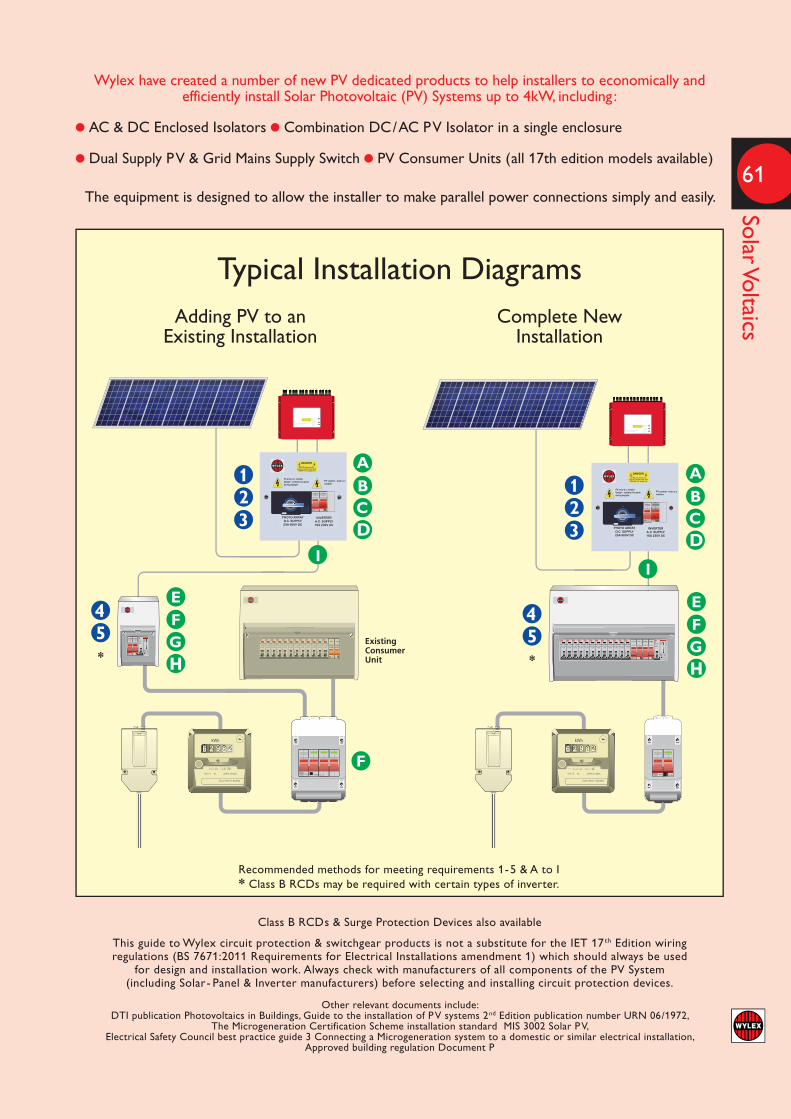
61
Solar Voltaics
ExistingConsumerUnit
123
45
A
CD
B
E
GF
F
E
G
II
F
123
A
CD
B
45
* *
NN L L Cat.No.
Wylex have created a number of new PV dedicated products to help installers to economically andefficiently install Solar Photovoltaic (PV) Systems up to 4kW, including :
l AC & DC Enclosed Isolators l Combination DC/AC PV Isolator in a single enclosure
l Dual Supply PV & Grid Mains Supply Switch l PV Consumer Units (all 17th edition models available)
The equipment is designed to allow the installer to make parallel power connections simply and easily.
Adding PV to an Complete New Existing Installation Installation
Typical Installation Diagrams
Class B RCDs & Surge Protection Devices also available
This guide to Wylex circuit protection & switchgear products is not a substitute for the IET 17th Edition wiringregulations (BS 7671:2011 Requirements for Electrical Installations amendment 1) which should always be used
for design and installation work. Always check with manufacturers of all components of the PV System(including Solar- Panel & Inverter manufacturers) before selecting and installing circuit protection devices.
Other relevant documents include: DTI publication Photovoltaics in Buildings, Guide to the installation of PV systems 2nd Edition publication number URN 06/1972,
The Microgeneration Certification Scheme installation standard MIS 3002 Solar PV, Electrical Safety Council best practice guide 3 Connecting a Microgeneration system to a domestic or similar electrical installation,
Approved building regulation Document P
Recommended methods for meeting requirements 1-5 & A to I* Class B RCDs may be required with certain types of inverter.

62
Locked Consumer units
Isolation - Locked Consumer unitsAlthough Wylex in the past have offered a lockable consumer unit(access to the devices MCBs /RCBOs and Isolating Switch is covered bya lockable door); this unit can only be specified and used in certainmitigating circumstances for example power to fire alarm circuits islocked in the ‘On’ position (via interlocks) to ensure the safety circuit isnever isolated unless authorised (via interlocking procedure).
Wylex’s view on “lockable consumer units” is inline with good safetypractice; in that you should object to locking power in an “On” positionwithout the means of local isolation, especially in the case of an‘Emergency’ to achieve immediate electrical shut down. The Main Switch/ Isolator provided in a consumer unit is deemed the main isolationpoint for the installation and is automatically classed as the EmergencySwitching point for isolating the complete installation in an crisissituation.
In the case of an emergency and the immediate need to isolate thepower; if the Main Switch of the consumer unit can only be actuated(turned off) by obtaining a key (kept separate away from the unit) tounlock the door, to gain access to the switch, this can be interpreted byits numerous operations as against good safety practice.
Extracts from various regulations that support this view are as follows:-
BS 7671:2008 17th Edition wiring regulations: Incorporating amendment No1:2011
CHAPTER 13 FUNDAMENTAL PRINCIPLES
132.15.1 Effective means, suitably placed ready for operation, shall beprovided so that all voltage may be cut off from every installation, fromevery circuit thereof and from all equipment, as may be necessary toprevent or remove danger.
537 ISOLATING AND SWITCHING
537.1.3 Each installation shall have the provision for disconnection fromsupply.
537.1.4 A main linked switch or linked circuit-breaker shall be providedas near as practicable to the origin of every of every installation as ameans of switching the supply on load and as a means of isolation. Amain switch intended for operation by ordinary persons, e.g. of ahousehold or similar installation, shall interrupt both live conductors ofa single-phase supply.
537.4 Emergency Switching
537.4.1.1 Means shall be provided for emergency switching of any partof an installation where it may be necessary to control the supply toremove an unexpected danger.
537.4.1.3 Means for emergency switching shall act as directly as possibleon the appropriate supply conductors. The arrangement shall be thatone single action only will interrupt the appropriate supply.
537.4.1.4 The arrangement of the emergency switching shall be suchthat its operation does not introduce a further danger or interfere withthe complete operation necessary to remove the danger.
537.4.2.7 A device for emergency switching shall so be placed anddurably marked so as to be readily identifiable and convenient for theintended use.
ELECTRICAL SAFETY COUNCIL: (ADVICE TAKEN FROM THEIR WEB SITE/ LITERATURE).
A consumer unit or fusebox is used to control and distribute electricityaround our homes.
They usually contain:
A) Mains switch, B) Fuses or Circuit Breakers, C) Residual CurrentDevice
Mains Switch
The mains switch allows you to turn off the electricity supply to yourelectrical installation. Some electrical installations have more than onemains switch, for example, if your home is heated by electric storageheaters, you may have a separate consumer unit (fuse box) for them.The consumer unit should be easy to get to, so find out where themains switch is to turn the electricity off in an emergency.
LOCKING A CONSUMER UNIT TO STOP UNAUTHORISED ACCESS / ACTUATION OF THE PROTECTION DEVICES.
A request is sometimes made to lock the consumer unit because theinstaller / user don’t want unauthorised access to switch devices ‘On’and/or ‘Off’. In this case, the isolation point to switch ‘Off’ theinstallation and Emergency Switching requirements still applies to theconsumer unit and may be achieved in several ways. Wylex offer 3 costeffective options as follows:-
Option 1. Use a standard consumer unit with a MCB/ RCBO lockingdevice and padlock on the individual outgoing circuits to lock in the ‘On’or ‘Off’ position’s. When locked in the ‘On’ position the MCB / RCBOwill still ‘trip’ due to a fault condition on the circuit. (Note: you will needto open the padlock and remove the locking device to reset a trippedunit). The Main Switch Isolator is still accessible on the consumer unitto isolate the installation under emergency conditions.
Option 2. Have all the outgoing protection devices MCBs / RCBOsunder a separate lockable door / cover to stop unauthorized access /operation of the individual circuits. The operation of the Main SwitchIsolator is ‘outside’ of this lockable door / cover; via a protruding toggleswitch or door interlocked rotary handle connected to the Main SwitchIsolator. The operation of the Main Switch Isolator is still accessible /unhindered on the consumer unit to isolate the installation underemergency conditions.
Option 3. Have a lockable door on the complete consumer unitstopping unauthorised access to all the outgoing devices and MainSwitch Isolator fitted into the unit. In this case, the Consumer unit mustalso be fed by a separate Isolation Point that is “still local” (near aspracticable) to the consumer unit. This separate Isolation Device is usedto isolate the installation under emergency conditions. This IsolationPoint /Device should have easy access and is marked as the Emergency /Isolation Point for the particular consumer unit. The consumer unitshould also be marked in a way to indicate the emergency isolationpoint is separate / next to the unit and not part of the consumer unit.In this case, because it is not intuitive that the Isolation Point is notwithin / accessible directly on this consumer unit; Instructions should begiven to each user of the installation on how to isolate in emergencyconditions using the separate Isolation Point device.
Meter
CUTOUTFUSE
100AREC
ISOLATINGSWITCH
Typical arrangement with REC Isolating Switch
Locked Visor

63
MCBs - Technical D
ata
GENERAL CONSTRUCTION
Wylex MCBs are of the thermal-magnetic current limiting type.MCBs have an easy to operate handle with a trip-free toggle mechanism– so even when the handle is held in the ‘on’ position the MCB is freeto trip.
AMBIENT TEMPERATURE CONSIDERATIONS
Wylex MCBs are calibrated to meet the requirements of BS EN 60898,30°C Ref Calibration Temperature.At other temperatures the following rating factors should be used:
At 60°C 0.9 At 20°C 1.0 At 0°C 1.1
Adjacent thermal-magnetic MCBs should not be continuously loaded ator approaching their nominal rated currents when mounted inenclosures. It is good engineering practice to apply generous deratingfactors or make provision for adequate free air between devices.In these situations, and in common with other manufacturers, werecommend a 66% diversity factor is applied to the MCB nominal ratedcurrent where it is intended to load the MCBs continuously (in excessof 1 hour).
METHOD OF OPERATION
1 Moderate overload conditionsDetection of moderate overload conditions is achieved by the use of athermo-metal element which deflects in response to the current passingthrough it. The thermo-metal element moves against the trip barreleasing the trip mechanism.2 Short circuit conditionsWhen the current flowing through the MCB reaches a predeterminedlevel, the solenoid directly pulls in the plunger which forcibly separatesthe contacts and simultaneously releases the trip mechanism.3 Establishment of arc between fixed and moving contactsAs the moving contact moves away from the fixed contact, an arc isestablished. The arc runs along the arc runner to the arc chamberwhere it is split up between the plates and extinguished.The low inertia and consequent high speed of the moving contact has alimiting effect on the flow of fault current. The rapid development of thearc, together with its accelerated extinction in the arc chamber, BS EN 60898-2 gives a typical operating time of 3.5-5 milliseconds fora type B curve MCB.
CURRENT LIMITING ACTION
The high speed current limiting action ensures that the MCB operatesbefore the full prospective fault current is allowed to develop.Under fault conditions, damage can be sustained to the installation andassociated equipment due to the amount of energy that passes beforethe current is completely interrupted. The total energy let-throughdepends on the value of current and the time for which it flows, and isdenoted by the symbol I2t. The high speed current limiting action ofMCBs ensures that the energy let-through and any subsequent damageis minimised. This reduced energy let-through assists greatly with bothback-up and discrimination considerations.
CURRENT LIMITING EFFECT
Maximumprospectivefaultcurrent
Healthycircuitcurrent
Fault
20ms 20ms

64
MCB & RCBO – Technical Data
SHORT CIRCUIT CURRENT AS A MULTIPLE OF RATED CURRENT
OPE
RA
TIN
G T
IME
IN S
ECO
ND
S
2 HRS
1 HR
1,000
100
10
1.0
0.1
0.01
0.001
1 3 5 10 20 100 1,000
Type B
Type C
Type D
BACK-UP PROTECTION
Back-up protection is required only if the prospective short circuitcurrent at the point of installation exceeds the breaking capacity of theMCB. When providing back-up protection consideration must be givento discrimination between the MCB and fuse.
DISCRIMINATION
It is desirable that the protective device nearest the fault shouldoperate first. The low energy let through of modern MCBs providesbetter discrimination with HRC fuse back-up than is given by earliertypes of MCBs.
CONSUMER UNIT MCBs
Standards BS EN 60898-2 : 2006Rated voltage (single pole) 240VTripping characteristics Type B,CShort circuit rating 6kAReference calibration temperature 30°CTerminal capacity – outgoing cable 0.75 to 25mm2
CAT REF C CURVE RATING
NHXB06 NHXC06 6ANHXB10 NHXC10 10ANHXB16 NHXC16 16ANHXB20 NHXC20 20ANHXB32 NHXC32 32ANHXB40 NHXC40 40ANHXB50 NHXC50 50A
4x10²
Prospective short circuit current Ip/A
Let
-th
rou
gh I
2 t (
amp
2 /se
c)
103
6 8 103 2 3 4 6 1048
In=
2
3
4
6
8104
2
3
4
6
8105
40 A32 A25 A20 A16 A10 A
6 A
50 A
40 A
35 A
32 A
63 A
80 A100 A
125 A
BS88 FUSE 160A
2
1
1
HW
= 0
.01
sec
2
min melting pt (pre-arching) eg In=125A BS 88
max let-through I2t of MCB eg 6A
1 1.5 2 3 4 53 5
6 8 10 15 20 300.01
0.02
0.04
0.06
0.1
0.2
0.40.6
1
2
46
10
20
401
2
46
10
20
4060
120
Tri
pp
ing
tim
e
Min
ute
sS
eco
nd
s
1.13 1.45
7
Multiple of rated current
ac
NHX, NSB AND PSB DISTRIBUTION BOARDMCBs
Standards BSEN 60898 -2: 2006Rated Voltage 230/400 VoltsTripping characteristics Type B, C and DShort circuit rating 6kA and 10kAReference calibrationtemperature 30˚CTerminal capacity - outgoing cable 0.75 to 25mm2
NHXSBS, NSBS & PSBS RCBO(COMBINED MCB/RCD)
Standards BSEN 61009 -2: 1995 BSEN 61009 -1: 2004Rated Voltage 230 Volts -1 2004SP or SP with switched neutralTripping characteristics NSBS=B,C PSBS=C
Short circuit rating 6kA and 10kAReference calibrationtemperature 30˚CRated residual operatingcurrent 30mASingle module Type ATwo module Type ACTerminal capacity - 0.5 to 16mm2
outgoing cable
Unique live side busbar combi-terminal allowsconnection of cable up to 25mm2
Maximum neutral cable size 25mm2

65
Lifeline Range R
CDs – Technical D
ata
OPERATION
The RCD employs the current balance principle which involves the supplyconductors to the load (phase and neutral) being wound onto a commontransformer core to form the primary windings. Under healthy circuitconditions, the current in the phase conductor is equal to the current in theneutral, and the vector sum of the current is zero.In the event of an earth fault, an amount of current will flow to earth,creating an out of balance situation in the transformer assembly.This out of balance is detected by the secondary winding of the transformerand at a pre-determined level of out of balance will activate the tripmechanism.Single phase and neutral or three phase and neutral units (suitable for 3or 4 wire systems) are available, the latter being suitable for balancedor unbalanced 3 phase loads.The RCD trip mechanism will operate at a residual current of between 50–100% of its rating tripping current (sensitivity).
TRANSIENT EARTH LEAKAGE CURRENTS
All Wylex residual current devices incorporate a high level of immunity totripping when subjected to transient earth leakage currents.Such transients can occur when there is a significant level of capacitance toearth as can result from cable capacitance (particularly MICC) or RF filternetworks. Wylex RCDs are therefore less susceptible to nuisance trippingdue to transient earth leakage currents.
RESIDUAL TRIPPING CURRENTS
10mA-Used in special applications where additional protection against contact isessential due to the nature of the installation.
30mA-Tripping current designated by the IEE Wiring Regulations to provideadditional protection.
100mA-Suitable for use where protection is provided to guard against firehazard,etc, rather than to provide additional protection to personnel, and wherethe earthing requirements need supplementing by RCD protection.
100mA time delay-Suitable for use when total RCD protection is required to supplement thesystem earthing and where local 30mA RCDs are used to give additionalprotection. The time delay RCD will discriminate with the 30mA RCD.
300mA-For use in large installations where plant and equipment protection are themain considerations and high levels of earth leakage are experienced.
If using RCDs in series, discrimination can only be achieved by using Type Sdevices in series with Types A or AC. See chart below.
IEC PUBLICATION (60479) CURVES WITH WYLEX RCD CHARACTERISTICS SUPERIMPOSED
TIME/CURRENT ZONES OF EFFECT OF AC CURRENT (15–100Hz) ON PERSONS
FAULT CURRENT SENSITIVITY
As the equipment is fed from the mains electrical supply, in the event ofan earth fault the presence of semi-conductors may result in the normalac waveform being replaced by a non-sinusoidal fault current. In somecases the waveform may be rectified or chopped. These waveforms aresaid to contain a pulsating dc component which can either partiallydesensitise or totally disable a standard Type AC RCD.International standards IEC 61008 (RCCBs) and IEC 61009 (RCBOs)divide RCDs into two performance classes:
Type ACRCDs for which tripping is ensured for residual sinusoidal alternatingcurrents, whether suddenly applied or slowly arising.
Type ARCDs for which tripping is ensured for residual sinusoidal alternatingcurrents and residual pulsating direct currents, whether suddenlyapplied or slowly arising.
To ensure the correct level of protection, check for the followingsymbols:
TYPE ACnormal ac sensitivity
TYPE Apulsating dc sensitivity
Wylex RCDs are available as both Type AC and Type A devices.
Technical details for Type B RCDs available on request.
10,000
5,000
2000
1000
500
200
100
50
20
100.1 0.2 0.3 0.5 1 2 3 5 10 20 30 50 100 200 300 500 1,000 2,000 10,000
mA5,0003,000
Body current in milliamperes (RMS)
100mA30mA
Typical current Limits due to body resistanceat 230V
1 2 3 4
a b c1 c2 c3 IEC 60479
Tim
e in
millise
con
ds
Zone Physiological effects
1 Usually no reaction effects (no danger).
2 Usually no harmful physiological effects (usually no effects).
3 Usually no organic damage to be expected.Likelihood of muscular contraction anddifficulty of breathing, reversibledisturbances of formation and conductionof impulses in the heart, and transientcardiac arrest without ventricular fibrillationincreases with current magnitude and time.
4 In addition to the effects of zone 3,probability of ventricular fibrillationincreased up to 5% (Curve C2), up to 50%(Curve C3) and above 50% beyond CurveC3. Increasing with magnitude and time,pathyphysiological effects such as cardiacarrest, breathing arrest and heavy burns may occur.
BSEN61008-1:1995 RCBOs BSEN61009-1:1995l
Rated Residual Current (In) Tripping Type of RCD RCD to Trip between times 50%-100% In 1x In 2x In 5x In 500Amps Scope
Standard Any Value, eg 10, 30, 100mA 300ms 150ms 40ms 40ms Maximum-Trip
A & AC
Time Delay Greater than 30mA, eg 100mA
500ms 200ms 150ms 150ms Maximum-Trip (S) 130ms 60ms 50ms 40ms Minimum-Non Trip

66
NH MCB Distribution Boards
Switches Multipole: 415V 50Hz BSEN 60947-3 1992 Category of duty AC22A
MCBs BSEN 60898: 1991 Type B, C and DShort circuit rating 6 & 10kA
Distribution Boards BS EN 60439-3
Degree of For indoor use onlyProtection. (IP3X)
CAT REF DIMENSIONS A mm B mm C mm
NHSPN0051 210 188 105NHSPN0081 210 242 105NHSPN00111 210 293 105NHSPN00141 210 343 105NHSPN00161 210 394 105NHSPN00191 210 394 105
CAT REF DIMENSION A mm
NHTN4MR 490NHTN6MR 570 NHTN8MR 650 NHTN12MR 815NHTN16MR 895NHTN20MR 1000NHTN24MR 1140
Depth 165mm- all sizes
CAT REF DIMENSION A mm
NHTN2540MR 769NHTN2560MR 823NHTN2580MR 877NHTN25120MR 985NHTN25160MR 1093NHTN25200MR 1201NHTN25240MR 1309
*144mm
* including fixing feet which are 3.5mm high
107mm
37mm
430mm
Enclosure Top View
Cover & Door Top View
A
430mm
165mm
400mm
130mm
35mm
Enclosure Top View
Cover & Door Top View
B
B C
A
125A DISTRIBUTION BOARDS
SINGLE PHASE DISTRIBUTION BOARDS
250A DISTRIBUTION BOARDSCONSTRUCTION
Wylex NH MCB distribution boardenclosures are fabricated in heavy gauge steeland are rust protected and highly resistant toboth weathering and mechanical damage.Incorporated in the distribution boards aremulti-terminal dual earth and neutral bars.They are designed for ease of installation andhave ample wiring space.
The WYLEX PSB miniature circuit breakersare rated at 10kA and are of the fault limitingtype.
When a short circuit occurs, the currentoperates a solenoid which trips the mechanismand forces the moving contact away from thefixed contact. The arc generated is forced intoan arcing chamber which incorporates splitterplates, to divide and cool it, reducing the totaloperating time to less than 5ms, This high speedoperation substantially reduces the ‘let through’energy (I2t) keeping additional damage at thepoint of the fault to a minimum. Additionallythis allows discrimination with HRC fuses athigh fault levels.
STANDARDS
NHTN METER PACKS (EXTENSION)
CAT REF DIMENSIONS A mm B mm C mm
NHTN125MP 245 430 144NHTN250MP 245 430 144
NHAB DIN ACCESSORY BOXES
CAT REF DIN DIMENSION MODULES A mm
NHEB - 240NHEB/DIN 18 240NHAB 18 240 NHAB2 36 387 NHAB3 54 544 NHAB4 72 756NHAB5 90 856

67
NH125 PanelboardsApproximate
Overallwith Doors
193630
164525250
62.562.5
62.562.5
BA
M8 Fixing Holes
630
164525
59228 239
NH125-250A Incomer
Inc
CTs
Std CTs - 195mmMID CTs - 135mm*
* We would recommend the use of a cable spreader box forincoming 4c copper cables in excess of 70mm2 when usedin conjunction with the 250A integral MID meter option
253mm
NH125-400A Incomer
Inc
Std/MID CTs - 207mm325mm
CTs
Incomer: 150mm2 Cu CableMeter CTs: Std - 21mm x 25mm slots MID - 28mm diameter
Incomer:Max Lug Connection: 32mm Std or MID CTs 31mm x 36mm slots
Cableways Main Units
110
ApproximateOverallwith Doors
193630
164525250
62.562.5
62.562.5
BA
M8 Fixing Holes
630
164525
59228 239
NH125-250A Incomer
Inc
CTs
Std CTs - 195mmMID CTs - 135mm*
* We would recommend the use of a cable spreader box forincoming 4c copper cables in excess of 70mm2 when usedin conjunction with the 250A integral MID meter option
253mm
NH125-400A Incomer
Inc
Std/MID CTs - 207mm325mm
CTs
Incomer: 150mm2 Cu CableMeter CTs: Std - 21mm x 25mm slots MID - 28mm diameter
Incomer:Max Lug Connection: 32mm Std or MID CTs 31mm x 36mm slots
Cableways Main Units
110
250A PANELBOARD
DIMENSIONSH W D Modules
6 Way 912 630 164 12
8 Way 988 630 164 13
12 Way 1140 630 164 15
16 Way 1292 630 164 17
250A CABLE WAYS
6 Way 912 250 180 12
8 Way 988 250 180 13
12 Way 1140 250 180 15
16 Way 1292 250 180 17
400A PANELBOARD
DIMENSIONSH W D Modules
6 Way 1064 630 164 14
8 Way 1140 630 164 15
12 Way 1292 630 164 17
16 Way 1444 630 164 19
400A CABLE WAYS
6 Way 1064 250 180 14
8 Way 1140 250 180 15
12 Way 1292 250 180 17
16 Way 1444 250 180 19
MAIN UNITS 250A
DIMENSIONSA B
6 Way 912 787
8 Way 988 863
12 Way 1140 1015
16 Way 1292 1167
MAIN UNITS 400A
6 Way 1064 939
8 Way 1140 1015
12 Way 1292 1167
16 Way 1444 1319
NH125 PANELBOARD DIMENSIONS (mm)
MAIN UNITS
ADD-ON UNITS
AVAILABLE SPREADING ROOM FOR INCOMING CABLES
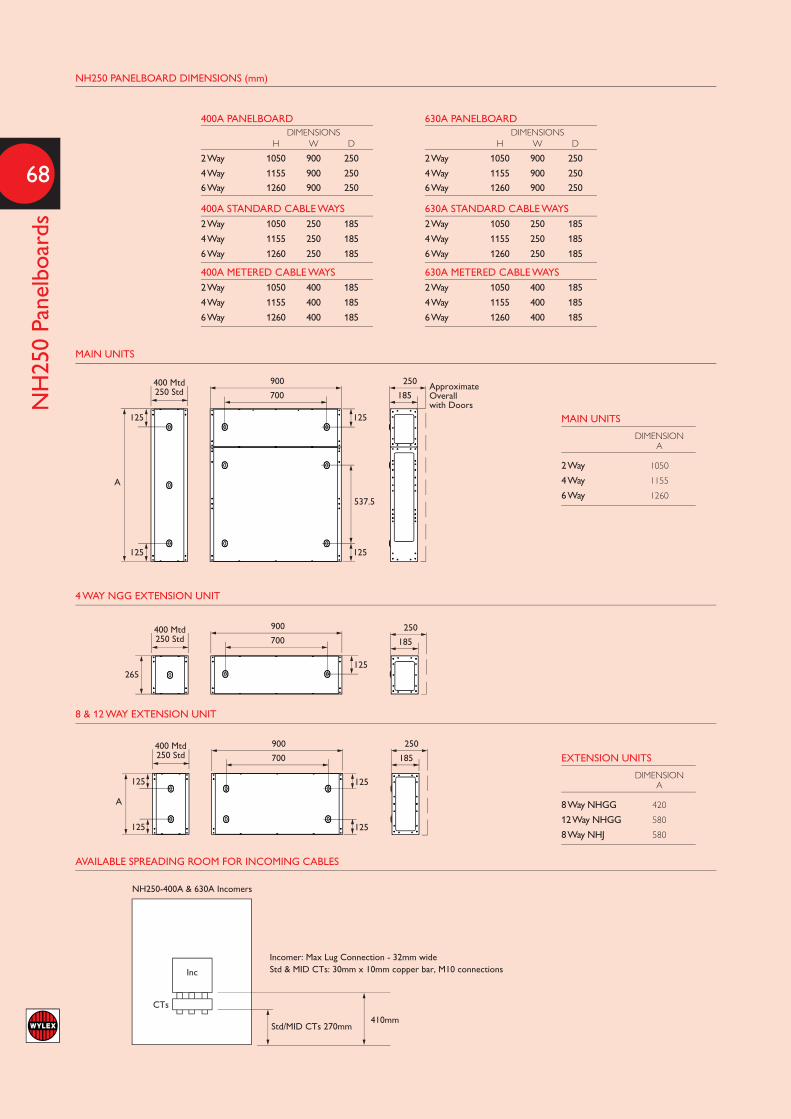
68
NH250 Panelboards
ApproximateOverallwith Doors
250
185
250
185
250
185
700
900
400 Mtd250 Std
400 Mtd250 Std
400 Mtd250 Std
700
900
700
900
125
125
265
125
125
537.5
125
125
125
A
125
125
A
NH250-400A & 630A Incomers
Inc
CTs
Std/MID CTs 270mm410mm
Incomer: Max Lug Connection - 32mm wideStd & MID CTs: 30mm x 10mm copper bar, M10 connections
400A PANELBOARDDIMENSIONS
H W D
2 Way 1050 900 250
4 Way 1155 900 250
6 Way 1260 900 250
400A STANDARD CABLE WAYS2 Way 1050 250 185
4 Way 1155 250 185
6 Way 1260 250 185
400A METERED CABLE WAYS2 Way 1050 400 185
4 Way 1155 400 185
6 Way 1260 400 185
630A PANELBOARDDIMENSIONS
H W D
2 Way 1050 900 250
4 Way 1155 900 250
6 Way 1260 900 250
630A STANDARD CABLE WAYS2 Way 1050 250 185
4 Way 1155 250 185
6 Way 1260 250 185
630A METERED CABLE WAYS2 Way 1050 400 185
4 Way 1155 400 185
6 Way 1260 400 185
NH250 PANELBOARD DIMENSIONS (mm)
MAIN UNITS
DIMENSIONA
2 Way 1050
4 Way 1155
6 Way 1260
EXTENSION UNITS
DIMENSIONA
8 Way NHGG 420
12 Way NHGG 580
8 Way NHJ 580
MAIN UNITS
4 WAY NGG EXTENSION UNIT
8 & 12 WAY EXTENSION UNIT
AVAILABLE SPREADING ROOM FOR INCOMING CABLES

69
NHGG MCCB C
haracteristics
NHGG TIME / CURRENT CHARACTERISTICS
125A
80-1
00A
60-7
0A
50A
45A
30-3
5A
15A
NHGG15, 20, 25, 30, 40,
50, 60, 80, 100,110, 125 Amp
65kA 25kA
240VSymmetrical RMS Amperes
480VType Maximum Trip
Unit Rating n
FROM THE 5 SEC VALUE FOR THE 125A BREAKER, THE ABOVE CURVE SUGGESTS A OHMIC VALUE OF 0,33 OHMS
5 SEC VALUES (230V / 5.5X IN) FOR OTHER RATINGS ARE AS FOLLOWS
Ampere 20 25 30 40 50 60 80 100 125
Ohm 2.09 1.67 1.39 1.05 0.84 0.70 0.52 0.42 0.33

70
NHJ MCCB Characteristics
NHJ TIME / CURRENT CHARACTERISTICS
NHL TIME / CURRENT CHARACTERISTICS
x In1 2 5 20 50100.1 0.2 0.5
0.01
0.01
10
100
1000
10000
t [s]
0.01
0.1
0.1
0.1
1
x
4x 4x8x 8x
4x 4x8x 8x
4x 4x8x 8x
I
L
Ii
Ii
IiIn = 100 A
In = 160 A
In = 250 A
In = 100 AIn = 160 AIn = 250 A
Ir Ii
33
Irmin. max.
xIn1 2 5 20 50100.1 0.2 0.5
Ir = 575 A.630 A ~ Ii = 7 kA
4x12.5x
4x12.5x
4x12.5x
4x12.5x
4x12.5x
4x12.5x
I
In = 250 A
In = 400 A
In = 630 A Ii
Ii
Ii
In = 250 AIn = 400 AIn = 630 A
L
Ir Ii
0.01
0.01
10
100
1000
10000
t [s]
0.01
0.1
0.1
0.1
1
Irmin. max.
33
IR & II SET AT MINIMUM
CURRENT VALUE (A) OHMIC VALUE0.4 5 0.4 5
AMPS SECONDS SECONDS VOLTAGE SECONDS SECONDS
100 150A 150A 230V 1.533Ω 1.533Ω
160 240A 240A 230V 0.958Ω 0.958Ω
250 375A 375A 230V 0.613Ω 0.613Ω
IR SET AT MINIMUM & II SET AT MAXIMUM
100 320A 230A 230V 0.719Ω 1.000Ω
160 512A 368A 230V 0.449Ω 0.625Ω
250 800A 575A 230V 0.288Ω 0.400Ω
IR & II SET AT MAXIMUM
100 800A 600A 230V 0.288Ω 0.383Ω
160 1280A 960A 230V 0.180Ω 0.240Ω
250 2000A 1500A 230V 0.115Ω 0.153Ω
IR SET AT MAXIMUM & II SET AT MINIMUM
100 400A 400A 230V 0.575Ω 0.575Ω
160 640A 640A 230V 0.359Ω 0.359Ω
250 1000A 1000A 230V 0.230Ω 0.230Ω
IR & II SET AT MINIMUM
CURRENT VALUE (A) OHMIC VALUE0.4 5 0.4 5
AMPS SECONDS SECONDS VOLTAGE SECONDS SECONDS
250 375A 375A 230V 0.613Ω 0.613Ω
400 600A 600A 230V 0.383Ω 0.383Ω
630 945A 945A 230V 0.243Ω 0.243Ω
IR SET AT MINIMUM & II SET AT MAXIMUM
250 1250A 575A 230V 0.184Ω 0.400Ω
400 2000A 920A 230V 0.115Ω 0.250Ω
630 3150A 1449A 230V 0.073Ω 0.159Ω
IR & II SET AT MAXIMUM
250 3125A 1500A 230V 0.074Ω 0.153Ω
400 5000A 2400A 230V 0.046Ω 0.096Ω
630 7875A 3780A 230V 0.029Ω 0.061Ω
IR SET AT MAXIMUM & II SET AT MINIMUM
250 1000A 1000A 230V 0.230Ω 0.230Ω
400 1600A 1600A 230V 0.144Ω 0.144Ω
630 2520A 2520A 230V 0.091Ω 0.091Ω

71
MESB C
ontactors
CONTACTORS
MESB-20NC MESB-24NC MESB-40NC MESB-63NCTYPE POWER (W) C(yF) I(A) MESB-20NO MESB-24NO MESB-40NO MESB-63NO 60 - 0.26 23 29 65 85 100 - 0.43 14 16 40 50Incandescent Lamps 200 - 0.87 7 8 20 25 500 - 2.17 3 3 8 10 1000 - 4.35 1 1 4 5 18 - 0.37 22 24 90 140Fluorescent Lamps
24 - 0.35 22 24 90 140uncorrected and
36 - 0.43 17 20 65 95Series correction
58 - 0.67 14 17 45 70 18 - 0.11 2 x 30 2 x 40 2 x 100 2 x 150Fluorescent Lamps 24 - 0.14 2 x 24 2 x 31 2 x 78 2 x 118lead- lag circuit 36 - 0.22 2 x 17 2 x 24 2 x 65 2 x 95 58 - 0.35 2 x 10 2 x 14 2 x 40 2 x 60 18 4.5 0.12 7 8 48 73Fluorescent Lamps 24 4.5 0.15 7 8 48 73Parallel correction 36 4.5 0.2 7 8 48 73 58 7 0.32 4 5 31 47 1 x 18 - 0.09 25 35 100 140 1 x 36 - 0.16 15 20 52 75Fluorescent Lamps 1 x 58 - 0.25 14 19 50 72with electronic 2 x 18 - 0.17 12 17 50 70ballast units (EVG) 2 x 36 - 0.32 7 10 26 38 2 x 58 - 0.49 7 9 25 36 50 - 0.61 14 18 38 55 80 - 0.8 10 13 29 42High-pressure 125 - 1.15 7 9 20 29Mercury-vapour Lamps 250 - 2.15 4 5 10 15uncorrected 400 - 3.25 2 3 7 10 700 - 5.4 1 2 4 6 1000 - 7.5 1 1 3 4 50 7 0.28 4 5 31 47 80 8 0.41 4 5 27 41High Pressure 125 10 0.65 3 4 22 33Mercury-vapour Lamps 250 18 1.22 1 2 12 18Parallel correction 400 25 1.95 1 1 9 13 700 45 3.45 - - 5 7 1000 60 4.8 - - 4 5 35 - 0.53 18 22 43 60 70 - 1 10 12 23 32
Halogen metal -vapour 150 - 1.8 5 7 12 18
250 - 3 3 4 7 10Lamps uncorrected 400 - 3.5 3 3 6 9 1000 - 9.5 1 1 2 3 2000 - 16.5 - - 1 1 35 6 0.25 5 6 36 50 70 12 0.45 2 3 18 25
Halogen metal -vapour 150 20 0.75 1 1 11 15
250 33 1.5 - 1 6 9Lamps Parallel correction 400 35 2.5 - 1 6 8 1000 95 5.8 - - 2 3 2000 148 11.5 - - 1 2 150 - 1.8 5 6 17 22High-pressure Sodium-vapour 250 - 3 3 4 10 13Lamps uncorrected 400 - 4.7 2 2 6 8 1000 - 10.3 - 1 3 3 150 20 0.83 1 1 11 16High-pressure Sodium-vapour 250 33 1.5 - 1 6 10Lamps parallel 400 48 2.4 - - 4 6 1000 106 6.3 - - 2 3 18 - 0.35 22 27 71 90 35 - 1.5 7 9 23 30Low-pressure 55 - 1.5 7 9 23 30Sodium-vapour Lamps 90 - 2.4 4 5 14 19uncorrected 135 - 3.5 3 4 10 13 180 - 3.3 3 4 10 13 18 5 0.35 6 7 44 66 35 20 0.31 1 1 11 16Low-pressure 55 20 0.42 1 1 11 16Sodium-vapour Lamps 90 26 0.63 1 1 8 12Parallel correction 135 45 0.94 - - 4 7 180 40 1.16 - - 5 8
Thermal Rating per Pole Motor Rating AC3 (kW)
230V 400V
MESB-20NC MESB-20NO 20 1.3 -MESB-24NC MESB-24NO 24 2.2 4MESB-40NC MESB-40NO 40 5.5 11 - MESB-63NO 63 8.5 15
AC Ratings in accordance with BSEN60947-5-1 and BSEN 60947-4-1Definitions: AC1 Primarily Resistive Load but may be slightly inductive AC3 Medium-Starting-duty motors, starting and switching off of squirrel -cage motors
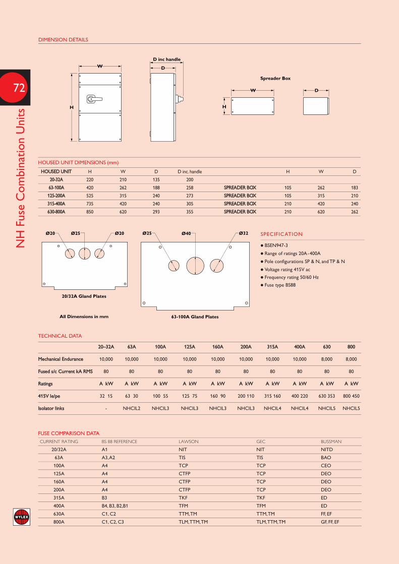
72
NH Fuse Combination Units
DIMENSION DETAILS
Ø20 Ø20Ø25
20/32A Gland Plates
63-100A Gland PlatesAll Dimensions in mm
Ø25 Ø32Ø40Ø20 Ø20Ø25
20/32A Gland Plates
63-100A Gland PlatesAll Dimensions in mm
Ø25 Ø32Ø40
W D
D
D inc handle
H
W
Spreader Box
H
W D
D
D inc handle
H
W
Spreader Box
H
HOUSED UNIT DIMENSIONS (mm)
HOUSED UNIT H W D D inc. handle H W D
20-32A 220 210 135 200
63-100A 420 262 188 258 SPREADER BOX 105 262 183
125-200A 525 315 240 273 SPREADER BOX 105 315 210
315-400A 735 420 240 305 SPREADER BOX 210 420 240
630-800A 850 620 293 355 SPREADER BOX 210 620 262
FUSE COMPARISON DATA
CURRENT RATING BS 88 REFERENCE LAWSON GEC BUSSMAN
20/32A A1 NIT NIT NITD
63A A3, A2 TIS TIS BAO
100A A4 TCP TCP CEO
125A A4 CTFP TCP DEO
160A A4 CTFP TCP DEO
200A A4 CTFP TCP DEO
315A B3 TKF TKF ED
400A B4, B3, B2,B1 TFM TFM ED
630A C1, C2 TTM, TM TTM, TM FF, EF
800A C1, C2, C3 TLM, TTM, TM TLM, TTM, TM GF, FF, EF
TECHNICAL DATA
20–32A 63A 100A 125A 160A 200A 315A 400A 630 800
Mechanical Endurance 10,000 10,000 10,000 10,000 10,000 10,000 10,000 10,000 8,000 8,000
Fused s/c Current kA RMS 80 80 80 80 80 80 80 80 80 80
Ratings A kW A kW A kW A kW A kW A kW A kW A kW A kW A kW
415V le/pe 32 15 63 30 100 55 125 75 160 90 200 110 315 160 400 220 630 353 800 450
Isolator links - NHCIL2 NHCIL3 NHCIL3 NHCIL3 NHCIL3 NHCIL4 NHCIL4 NHCIL5 NHCIL5
SPECIFICATION
l BSEN947-3
l Range of ratings 20A-400A
l Pole configurations SP & N, and TP & N
l Voltage rating 415V ac
l Frequency rating 50/60 Hz
l Fuse type BS88
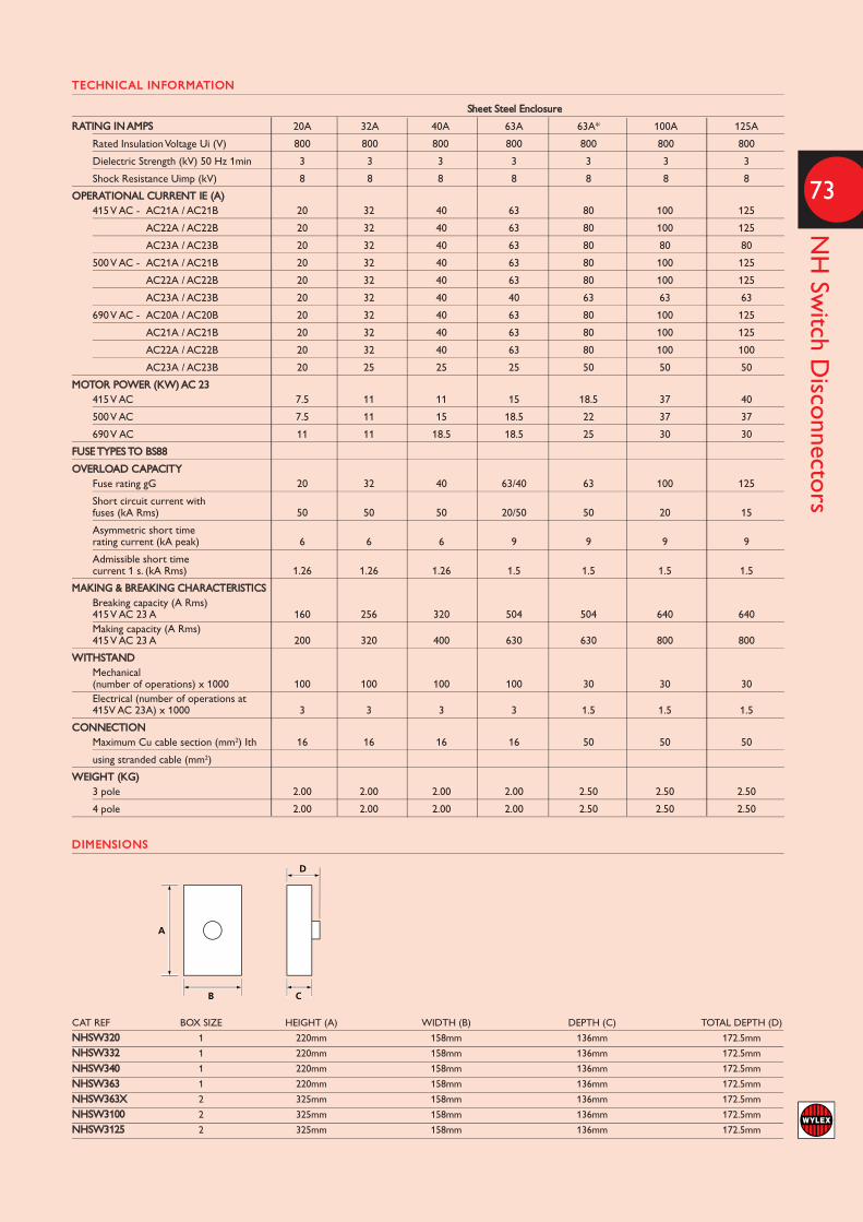
73
NH Switch D
isconnectors
DIMENSIONS
TECHNICAL INFORMATION
Sheet Steel Enclosure
RATING IN AMPS 20A 32A 40A 63A 63A* 100A 125A
Rated Insulation Voltage Ui (V) 800 800 800 800 800 800 800
Dielectric Strength (kV) 50 Hz 1min 3 3 3 3 3 3 3
Shock Resistance Uimp (kV) 8 8 8 8 8 8 8
OPERATIONAL CURRENT IE (A) 415 V AC - AC21A / AC21B 20 32 40 63 80 100 125
AC22A / AC22B 20 32 40 63 80 100 125
AC23A / AC23B 20 32 40 63 80 80 80
500 V AC - AC21A / AC21B 20 32 40 63 80 100 125
AC22A / AC22B 20 32 40 63 80 100 125
AC23A / AC23B 20 32 40 40 63 63 63
690 V AC - AC20A / AC20B 20 32 40 63 80 100 125
AC21A / AC21B 20 32 40 63 80 100 125
AC22A / AC22B 20 32 40 63 80 100 100
AC23A / AC23B 20 25 25 25 50 50 50
MOTOR POWER (KW) AC 23 415 V AC 7.5 11 11 15 18.5 37 40
500 V AC 7.5 11 15 18.5 22 37 37
690 V AC 11 11 18.5 18.5 25 30 30
FUSE TYPES TO BS88
OVERLOAD CAPACITY Fuse rating gG 20 32 40 63/40 63 100 125
Short circuit current with fuses (kA Rms) 50 50 50 20/50 50 20 15
Asymmetric short time rating current (kA peak) 6 6 6 9 9 9 9
Admissible short time current 1 s. (kA Rms) 1.26 1.26 1.26 1.5 1.5 1.5 1.5
MAKING & BREAKING CHARACTERISTICS Breaking capacity (A Rms) 415 V AC 23 A 160 256 320 504 504 640 640 Making capacity (A Rms) 415 V AC 23 A 200 320 400 630 630 800 800
WITHSTAND Mechanical (number of operations) x 1000 100 100 100 100 30 30 30 Electrical (number of operations at 415V AC 23A) x 1000 3 3 3 3 1.5 1.5 1.5
CONNECTION Maximum Cu cable section (mm2) Ith 16 16 16 16 50 50 50
using stranded cable (mm2)
WEIGHT (KG) 3 pole 2.00 2.00 2.00 2.00 2.50 2.50 2.50
4 pole 2.00 2.00 2.00 2.00 2.50 2.50 2.50
A
B C
D
A
B C
D
CAT REF BOX SIZE HEIGHT (A) WIDTH (B) DEPTH (C) TOTAL DEPTH (D)
NHSW320 1 220mm 158mm 136mm 172.5mmNHSW332 1 220mm 158mm 136mm 172.5mmNHSW340 1 220mm 158mm 136mm 172.5mmNHSW363 1 220mm 158mm 136mm 172.5mmNHSW363X 2 325mm 158mm 136mm 172.5mmNHSW3100 2 325mm 158mm 136mm 172.5mmNHSW3125 2 325mm 158mm 136mm 172.5mm

74
Standard Range - Dimensions
STANDARD RANGE
CAT REF DIMENSIONS Terminal A B C Capacity
832A 62 76 30 10
860A 57 79 29 25
CAT REF DIMENSIONS Terminal A B C Capacity
921X 72 45 48 10
921E 114 133 61 10
REC2S 78 150 65 50
REC2 100 150 65 50
REC3 100 150 65 50
REC4 100 150 65 50
METAL-MAIN SWITCH ISOLATOR
CAT REF DIMENSIONS A B C
206 140 131 93
306 210 153 99
406 210 153 99
606 293 210 104
CAT REF DIMENSIONSIP RATING A B C
ESE2 IP40 60 153 60ESE2L IP20 60 140 60WBE3 IP65 85 160 114ESI4 IP40 100 150 68ESM6 IP40 90 225 62ESM7 IP54 90 225 89ESE4 IP20 77 140 65WBE4 IP65 110 160 114ESM11 IP54 120 225 95ESM13 IP54 137 318 104ESM8 IP40 120 225 70
INSULATED-MAIN SWITCH ISOLATOR
CAT REF DIMENSIONS A B C
104 98 121 68
204 125 120 70
304 190 155 95
404 190 155 95
604 272 186 103
804 323 186 103
108/160/160C 143 178 99
METAL-45A AND 60A SWITCHFUSES
CAT REF DIMENSIONS A B C
106 112 131 80
108M/160CM 172 242 98
METAL-100A DOUBLE POLE SWITCHFUSE
CAT REF DIMENSIONS A B C
110M 178 305 76
110M/80 178 305 76
110M/63 178 305 76
CA
B
FUSES
A
B
C
A
C
B
A C
B
ENCLOSURES
ISOLATORS

75
Metering Technical D
ata
METERING - TECHNICAL DATA
General Characteristics
Housing Width 2 modules DIN 4 modules DIN
Mounting 35mm DIN rail 35mm DIN rail
Depth 70mm 70mm
Reference standard EN 50470-1-3 (B), EN 62053-23-31 EN 50470-1-3 (B), EN 62053-23-31
Operating Features
Connectivity 2 2-3-4
Storage of energy values and configuration yes yes
Display tariffs identifier T1 and T2 T1 and T2
Supply
Rated control supply voltage Un 230 VAC 230 VAC
Operating range voltage 184 … 276 V 184 … 276 V
Rated frequency fn 50 Hz 50 Hz
Rated power dissipation (max.) Pv ≤8 (0.6) VA (W) ≤8 (0.6) VA (W)
Display (readouts)
Connection errors and phase out - PHASE Err
Display type LCD - Digits 7 (1 decimal) - 6mm x 3mm 8 (1 decimal) - 6mm x 3mm
Active energy: 1 display, 7-digit 000000.0 … 999999.9 kWh 0000000.0 … 999999.9 kWh
+ display import or export (arrow) 999999.9 … 000000.0 kWh 9999999.9 … 000000.0 kWh
Reactive energy: 1 display, 7-digit 000000.0 … 999999.9 kWh 0000000.0 … 999999.9 kWh
+ display import or export (arrow) 999999.9 … 000000.0 kWh 9999999.9 … 000000.0 kWh
Instantaneous active power: 1 display, 3-digit 000 … 999 W, kW or MW 000 … 999 W, kW or MW
Instantaneous reactive power: 1 display, 3-digit 000 … 999 var, kvar or Mvar 000 … 999 var, kvar or Mvar
Instantaneous tariff measurement 1 display, 1 digit T1 or T2 1 display, 1 digit T1 or T2
Display period refresh (seconds) 1 2
Measuring accuracy
Active energy and power ±1% (B) ±1% (B)
Reactive energy and power ±2 % ±2 %
Pulse output SO
Pulse output yes yes
Pulse quantity 1000 imp/kWh 500 imp/kWh
Pulse duration 30 ±2 ms 30 ±2 ms
Required voltage 5 … 230 ±5% (5 …300) VAC (DC) 5 … 230 ±5% (5 …300) VAC (DC)
Permissible current 90 mA 90 mA
Permissible current 1mA 1mA
80 A SP 80 A TP
Single Phase and Three PhaseMeasuring DevicesDirect Connected kW Meters - No external current transformersrequired.Standard reading or MID calibratedoptions. All meters have pulsed output forBuilding Management Systems. (BMS)
MID approval Under the Electricity Act 1989 allelectricity meters used for billingpurposes must be approved. The approval for these meters isobtained by conforming to theEuropean Measuring InstrumentsDirective (MID) 2004/22/EC(replacing OFGEM approval). Thisdirective covers a number of differentInstruments that are used to measureproducts or services for reselling.Therefore not only does it apply toElectrical Meters but you may seeMID approval on a range of itemssuch as the charge meter in a taxi,beer and wine glasses (the volumemeasurement line) in a Public Houseor on the petrol pumps when you arefilling up your vehicle.
Who should be using MIDcertified meters?By Law, anyone who is taking a meterreading that is then used for billingpurposes and for which theysubsequently receive a payment fromthe user for the electricity consumed.
Some typical examples:l A Retail shopping centre ownerwants to measure the individualconsumption of all the storeowners in his shopping mall andsend them separate invoices forthe electricity that each has usedto run their business.
l A Landlord who wants to measurethe electricity used by tenantsrenting apartments in his buildingand then send them a bill for theelectricity they have used.
l A caravan/mobile home LeisurePark wants to measure theconsumption of its customers andcharge them an exact amount forthe electricity used at the end oftheir rental period.
All of these examples must have theelectricity consumption reading takenfrom a certified MID approved meter.The MID certification validates thatthe meter is manufactured usingquality components, assures themeter is accurate for electricity billingpurposes and that it maintains thisaccuracy over time for consistentreadings.
Standard Meters - NonMID approvedIf a meter is being used purely for a“check meter reading” and not beingused to resell or charge for electricityconsumed, then a standard meter thatis reasonably accurate may be used tomeasure energy used at that point intime. For example, a check meterreading is required to meet L2Building Regulations and CharteredInstitution of Building ServicesEngineers TM39 guide to BuildingEnergy Metering. The reading taken isused as a ‘check point’ to help reduceenergy consumption.

List No Page No
104 54
106 45, 54
106RED 45, 54
108 54
108M 45, 54
110M 45, 54
110M/63 45, 54
110M/80 45, 54
160C 54
160CM 45, 54
204 54
206 54
304 54
306 54
404 54
406 54
604 54
606 54
804 54
921E 47
921X 47
B6 55
B10 55
B16 55
B20 55
B32 55
B40 55
C5 55
C15 55
C20 55
C30 55
C35 55
C40 55
C45 55
CFL05 55
CFL10 55
CFL15 55
CFL20 55
CFL30 55
CFL35 55
List No Page No
CFL40 55
CFL45 55
ESM11 51
ESM13 51
ESM6 51
ESM7 51
ESM8 51
ESE2 51
ESE2L 51
ESE4 51
ESi2S 51
ESi4 51
FALNH1206 10
FALNH1706 10
FALNH806 10
FALNHISS10SL 10
FALNHISS15SL 10
FALNHISS4606 10
FALNHISS5506 10
FALNHISS8706 10
FALNHRS10SL 10
FALNHRS10SSL 10
FALNHRS1106 10
FALNHRS13SSL 10
FALNHRS15SL 10
FALNHRS706 10
FALNHRS76206 10
FWC 55
L45 55
L60 55
LFL100 55
LFL45 55
LFL60 55
LFL63 55
LFL80 55
M10 55
MCBLDX 24, 27
ME242/230 11
MESB-20NC 27
MESB-20NO 11, 27
List No Page No
MESB-24NC 27
MESB-24NO 11, 27
MESB-40NC 27
MESB-40NO 11, 27
MESB-63NO 11, 27
MTS12/1 11
MTS6/1 11
MTS8 11
MTS8/1 11
NHPB125CTMID 34
NH00 11
NH00PP 11
NH1004IP 7
NH10DSMPVF 18
NH10DSRCBMPVDR 18
NH10DSRCBMPVHI 18
NH10DSRCBPVF 18
NH10ED4 51
NH10ED6 51
NH1104 5
NH1104+3 5
NH1106 8
NH1106+3 8
NH11DSMPVDR 18
NH11DSMPVHI 18
NH11DSPVF 18
NH11DSRCBPVDR 18
NH11DSRCBPVHI 18
NH12DSPVDR 18
NH12DSPVHI 18
NH12DSRCBMPVSL 18
NH13CBKIT 11
NH13DSMPVSL 18
NH13DSRCBPVSL 18
NH13ED4 51
NH13ED6 51
NH1404 5
NH1406 8
NH14DSPVSL 18
NH14DSRCBMPVF 18
List No Page No
NH15DSMPVF 18
NH15DSRCBPVF 18
NH16DSPVF 18
NH16ED4 51
NH16ED6 51
NH18BB1 24, 27
NH1904 5
NH1906 8
NH250DCK 23
NH250TPSWK 23
NH204/40 5
NH204/63 5
NH206/40 8
NH206/63 8
NH21ED4 51
NH21ED6 51
NH304IP 7
NH4ED4 51
NH4ED6 51
NH4PINKIT 23
NH504 5
NH504+3 5
NH506 8
NH506+3 8
NH5DSRCBMPVDR 18
NH6DSMPVDR 18
NH6DSRCBPVDR 18
NH704IP 7
NH7DSPVDR 18
NH7DSRCBMPVSL 18
NH7ED4 51
NH7ED6 51
NH804 5
NH804+3 5
NH804+6 5
NH806 8
NH806+3 8
NH806+6 8
NH8DSMPVSL 18
NH8DSRCBPVSL 18
76
Numeric Index
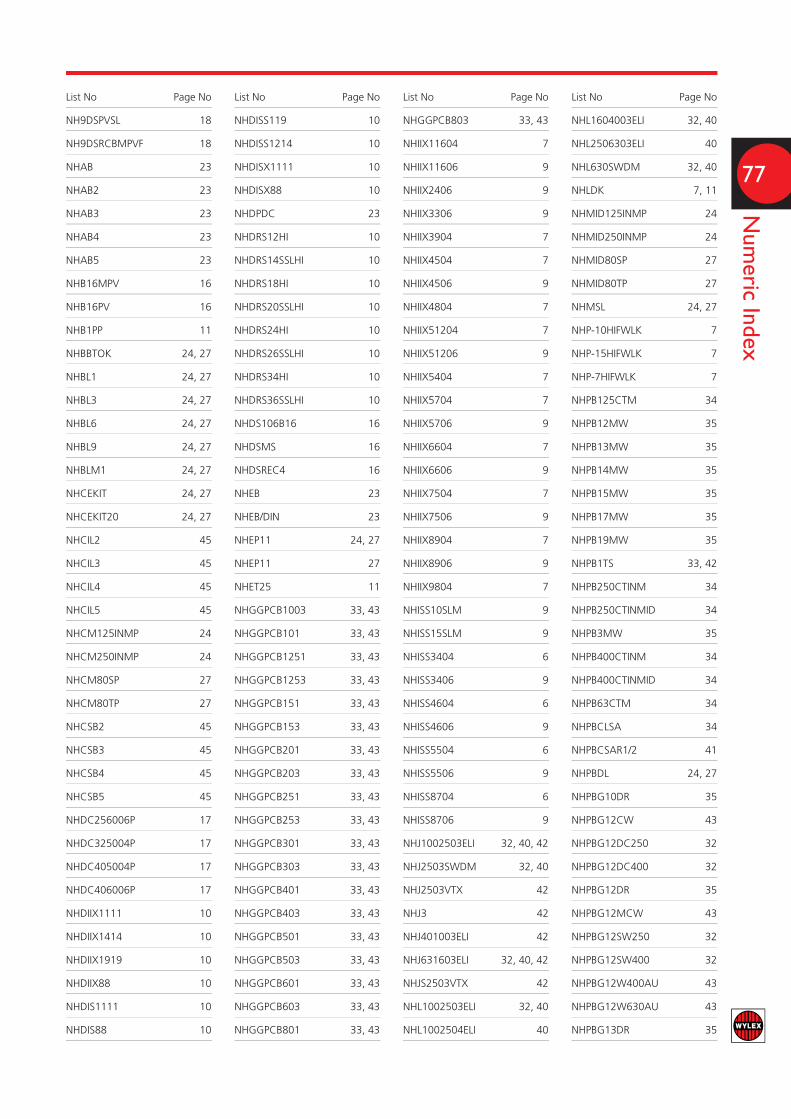
77
Numeric Index
List No Page No
NH9DSPVSL 18
NH9DSRCBMPVF 18
NHAB 23
NHAB2 23
NHAB3 23
NHAB4 23
NHAB5 23
NHB16MPV 16
NHB16PV 16
NHB1PP 11
NHBBTOK 24, 27
NHBL1 24, 27
NHBL3 24, 27
NHBL6 24, 27
NHBL9 24, 27
NHBLM1 24, 27
NHCEKIT 24, 27
NHCEKIT20 24, 27
NHCIL2 45
NHCIL3 45
NHCIL4 45
NHCIL5 45
NHCM125INMP 24
NHCM250INMP 24
NHCM80SP 27
NHCM80TP 27
NHCSB2 45
NHCSB3 45
NHCSB4 45
NHCSB5 45
NHDC256006P 17
NHDC325004P 17
NHDC405004P 17
NHDC406006P 17
NHDIIX1111 10
NHDIIX1414 10
NHDIIX1919 10
NHDIIX88 10
NHDIS1111 10
NHDIS88 10
List No Page No
NHDISS119 10
NHDISS1214 10
NHDISX1111 10
NHDISX88 10
NHDPDC 23
NHDRS12HI 10
NHDRS14SSLHI 10
NHDRS18HI 10
NHDRS20SSLHI 10
NHDRS24HI 10
NHDRS26SSLHI 10
NHDRS34HI 10
NHDRS36SSLHI 10
NHDS106B16 16
NHDSMS 16
NHDSREC4 16
NHEB 23
NHEB/DIN 23
NHEP11 24, 27
NHEP11 27
NHET25 11
NHGGPCB1003 33, 43
NHGGPCB101 33, 43
NHGGPCB1251 33, 43
NHGGPCB1253 33, 43
NHGGPCB151 33, 43
NHGGPCB153 33, 43
NHGGPCB201 33, 43
NHGGPCB203 33, 43
NHGGPCB251 33, 43
NHGGPCB253 33, 43
NHGGPCB301 33, 43
NHGGPCB303 33, 43
NHGGPCB401 33, 43
NHGGPCB403 33, 43
NHGGPCB501 33, 43
NHGGPCB503 33, 43
NHGGPCB601 33, 43
NHGGPCB603 33, 43
NHGGPCB801 33, 43
List No Page No
NHGGPCB803 33, 43
NHIIX11604 7
NHIIX11606 9
NHIIX2406 9
NHIIX3306 9
NHIIX3904 7
NHIIX4504 7
NHIIX4506 9
NHIIX4804 7
NHIIX51204 7
NHIIX51206 9
NHIIX5404 7
NHIIX5704 7
NHIIX5706 9
NHIIX6604 7
NHIIX6606 9
NHIIX7504 7
NHIIX7506 9
NHIIX8904 7
NHIIX8906 9
NHIIX9804 7
NHISS10SLM 9
NHISS15SLM 9
NHISS3404 6
NHISS3406 9
NHISS4604 6
NHISS4606 9
NHISS5504 6
NHISS5506 9
NHISS8704 6
NHISS8706 9
NHJ1002503ELI 32, 40, 42
NHJ2503SWDM 32, 40
NHJ2503VTX 42
NHJ3 42
NHJ401003ELI 42
NHJ631603ELI 32, 40, 42
NHJS2503VTX 42
NHL1002503ELI 32, 40
NHL1002504ELI 40
List No Page No
NHL1604003ELI 32, 40
NHL2506303ELI 40
NHL630SWDM 32, 40
NHLDK 7, 11
NHMID125INMP 24
NHMID250INMP 24
NHMID80SP 27
NHMID80TP 27
NHMSL 24, 27
NHP-10HIFWLK 7
NHP-15HIFWLK 7
NHP-7HIFWLK 7
NHPB125CTM 34
NHPB12MW 35
NHPB13MW 35
NHPB14MW 35
NHPB15MW 35
NHPB17MW 35
NHPB19MW 35
NHPB1TS 33, 42
NHPB250CTINM 34
NHPB250CTINMID 34
NHPB3MW 35
NHPB400CTINM 34
NHPB400CTINMID 34
NHPB63CTM 34
NHPBCLSA 34
NHPBCSAR1/2 41
NHPBDL 24, 27
NHPBG10DR 35
NHPBG12CW 43
NHPBG12DC250 32
NHPBG12DC400 32
NHPBG12DR 35
NHPBG12MCW 43
NHPBG12SW250 32
NHPBG12SW400 32
NHPBG12W400AU 43
NHPBG12W630AU 43
NHPBG13DR 35
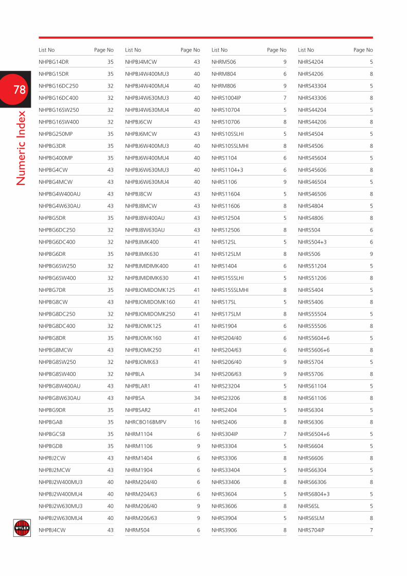
78
Numeric Index
List No Page No
NHPBG14DR 35
NHPBG15DR 35
NHPBG16DC250 32
NHPBG16DC400 32
NHPBG16SW250 32
NHPBG16SW400 32
NHPBG250MP 35
NHPBG3DR 35
NHPBG400MP 35
NHPBG4CW 43
NHPBG4MCW 43
NHPBG4W400AU 43
NHPBG4W630AU 43
NHPBG5DR 35
NHPBG6DC250 32
NHPBG6DC400 32
NHPBG6DR 35
NHPBG6SW250 32
NHPBG6SW400 32
NHPBG7DR 35
NHPBG8CW 43
NHPBG8DC250 32
NHPBG8DC400 32
NHPBG8DR 35
NHPBG8MCW 43
NHPBG8SW250 32
NHPBG8SW400 32
NHPBG8W400AU 43
NHPBG8W630AU 43
NHPBG9DR 35
NHPBGAB 35
NHPBGCSB 35
NHPBGDB 35
NHPBJ2CW 43
NHPBJ2MCW 43
NHPBJ2W400MU3 40
NHPBJ2W400MU4 40
NHPBJ2W630MU3 40
NHPBJ2W630MU4 40
NHPBJ4CW 43
List No Page No
NHPBJ4MCW 43
NHPBJ4W400MU3 40
NHPBJ4W400MU4 40
NHPBJ4W630MU3 40
NHPBJ4W630MU4 40
NHPBJ6CW 43
NHPBJ6MCW 43
NHPBJ6W400MU3 40
NHPBJ6W400MU4 40
NHPBJ6W630MU3 40
NHPBJ6W630MU4 40
NHPBJ8CW 43
NHPBJ8MCW 43
NHPBJ8W400AU 43
NHPBJ8W630AU 43
NHPBJIMK400 41
NHPBJIMK630 41
NHPBJMIDIMK400 41
NHPBJMIDIMK630 41
NHPBJOMIDOMK125 41
NHPBJOMIDOMK160 41
NHPBJOMIDOMK250 41
NHPBJOMK125 41
NHPBJOMK160 41
NHPBJOMK250 41
NHPBJOMK63 41
NHPBLA 34
NHPBLAR1 41
NHPBSA 34
NHPBSAR2 41
NHRCBO16BMPV 16
NHRM1104 6
NHRM1106 9
NHRM1404 6
NHRM1904 6
NHRM204/40 6
NHRM204/63 6
NHRM206/40 9
NHRM206/63 9
NHRM504 6
List No Page No
NHRM506 9
NHRM804 6
NHRM806 9
NHRS1004IP 7
NHRS10704 5
NHRS10706 8
NHRS10SSLHI 5
NHRS10SSLMHI 8
NHRS1104 6
NHRS1104+3 6
NHRS1106 9
NHRS11604 5
NHRS11606 8
NHRS12504 5
NHRS12506 8
NHRS12SL 5
NHRS12SLM 8
NHRS1404 6
NHRS15SSLHI 5
NHRS15SSLMHI 8
NHRS17SL 5
NHRS17SLM 8
NHRS1904 6
NHRS204/40 6
NHRS204/63 6
NHRS206/40 9
NHRS206/63 9
NHRS23204 5
NHRS23206 8
NHRS2404 5
NHRS2406 8
NHRS304IP 7
NHRS3304 5
NHRS3306 8
NHRS33404 5
NHRS33406 8
NHRS3604 5
NHRS3606 8
NHRS3904 5
NHRS3906 8
List No Page No
NHRS4204 5
NHRS4206 8
NHRS43304 5
NHRS43306 8
NHRS44204 5
NHRS44206 8
NHRS4504 5
NHRS4506 8
NHRS45604 5
NHRS45606 8
NHRS46504 5
NHRS46506 8
NHRS4804 5
NHRS4806 8
NHRS504 6
NHRS504+3 6
NHRS506 9
NHRS51204 5
NHRS51206 8
NHRS5404 5
NHRS5406 8
NHRS55504 5
NHRS55506 8
NHRS5604+6 5
NHRS5606+6 8
NHRS5704 5
NHRS5706 8
NHRS61104 5
NHRS61106 8
NHRS6304 5
NHRS6306 8
NHRS6504+6 5
NHRS6604 5
NHRS6606 8
NHRS66304 5
NHRS66306 8
NHRS6804+3 5
NHRS6SL 5
NHRS6SLM 8
NHRS704IP 7

Numeric Index
79
List No Page No
NHRS71004 5
NHRS71006 8
NHRS7504 5
NHRS7506 8
NHRS76204 5
NHRS76206 8
NHRS7704+3 5
NHRS7706+3 8
NHRS7SSLHI 5
NHRS7SSLMHI 8
NHRS804 6
NHRS804+3 6
NHRS804+6 6
NHRS806 9
NHRS8404 5
NHRS8406 8
NHRS8604+3 5
NHRS8904 5
NHRS8906 8
NHRS9304 5
NHRS9306 8
NHRS9804 5
NHRS9806 8
NHRS9SL 5
NHRS9SLM 8
NHRSX5704 7
NHRSX5706 9
NHRSX6604 7
NHRSX6606 9
NHRSX7504 7
NHRSX7506 9
NHRSX8904 7
NHRSX8906 9
NHRSX9804 7
NHRSX9806 9
NHSFBBC400 45
NHSFBBTM250 45
NHSPAK 23
NHSPMTRA 17
NHSPMTRD 17
List No Page No
NHSPN00111 22
NHSPN00141 22
NHSPN00161 22
NHSPN00191 22
NHSPN0051 22
NHSPN0081 22
NHSPSF100 45
NHSPSF20 45
NHSPSF32 45
NHSPSF63 45
NHSTM10704 6
NHSTM11604 6
NHSTM12504 6
NHSTM12SL 6
NHSTM12SLM 9
NHSTM17SL 6
NHSTM17SLM 9
NHSTM3604 6
NHSTM3606 9
NHSTM3904 6
NHSTM3906 9
NHSTM4504 6
NHSTM4506 9
NHSTM4804 6
NHSTM4806 9
NHSTM51204 6
NHSTM51206 9
NHSTM5404 6
NHSTM5406 9
NHSTM5704 6
NHSTM61104 6
NHSTM61106 9
NHSTM6304 6
NHSTM6306 9
NHSTM6604 6
NHSTM6606 9
NHSTM71004 6
NHSTM71006 9
NHSTM7504 6
NHSTM7506 9
List No Page No
NHSTM8404 6
NHSTM8904 6
NHSTM8906 9
NHSTM9304 6
NHSTM9306 9
NHSTM9804 6
NHSTM9806 9
NHSTM9SL 6
NHSTM9SLM 9
NHSW3100 47
NHSW3125 47
NHSW320 47
NHSW332 47
NHSW340 47
NHSW363 47
NHSW363X 47
NHTM1104 6
NHTM1106 9
NHTM1404 6
NHTM1904 6
NHTM504 6
NHTM506 9
NHTM804 6
NHTM806 9
NHTN125LP 25
NHTN125MP 24
NHTN12MR 22
NHTN16MR 22
NHTN20MR 22
NHTN24MR 22
NHTN250LP 25
NHTN250MP 24
NHTN25120MR 22
NHTN25160MR 22
NHTN25200MR 22
NHTN25240MR 22
NHTN2540MR 22
NHTN2560MR 22
NHTN2580MR 22
NHTN4MR 22
List No Page No
NHTN6MR 22
NHTN8MR 22
NHTPDC 23
NHTPSD16 17
NHTPSD25 17
NHTPSD32 17
NHTPSF100 45
NHTPSF125 45
NHTPSF160 45
NHTPSF20 45
NHTPSF200 45
NHTPSF315 45
NHTPSF32 45
NHTPSF400 45
NHTPSF63 45
NHTPSF630 45
NHTPSF800 45
NHXB06 11
NHXB10 11
NHXB16 11
NHXB20 11
NHXB32 11
NHXB40 11
NHXB50 11
NHXC06 11
NHXC10 11
NHXC16 11
NHXC20 11
NHXC32 11
NHXC40 11
NHXC50 11
NHXSBS1B06 11
NHXSBS1B10 11
NHXSBS1B16 11
NHXSBS1B20 11
NHXSBS1B32 11
NHXSBS1B40 11
NHXSBS1B50 11
NHXSBS1C06 11
NHXSBS1C10 11
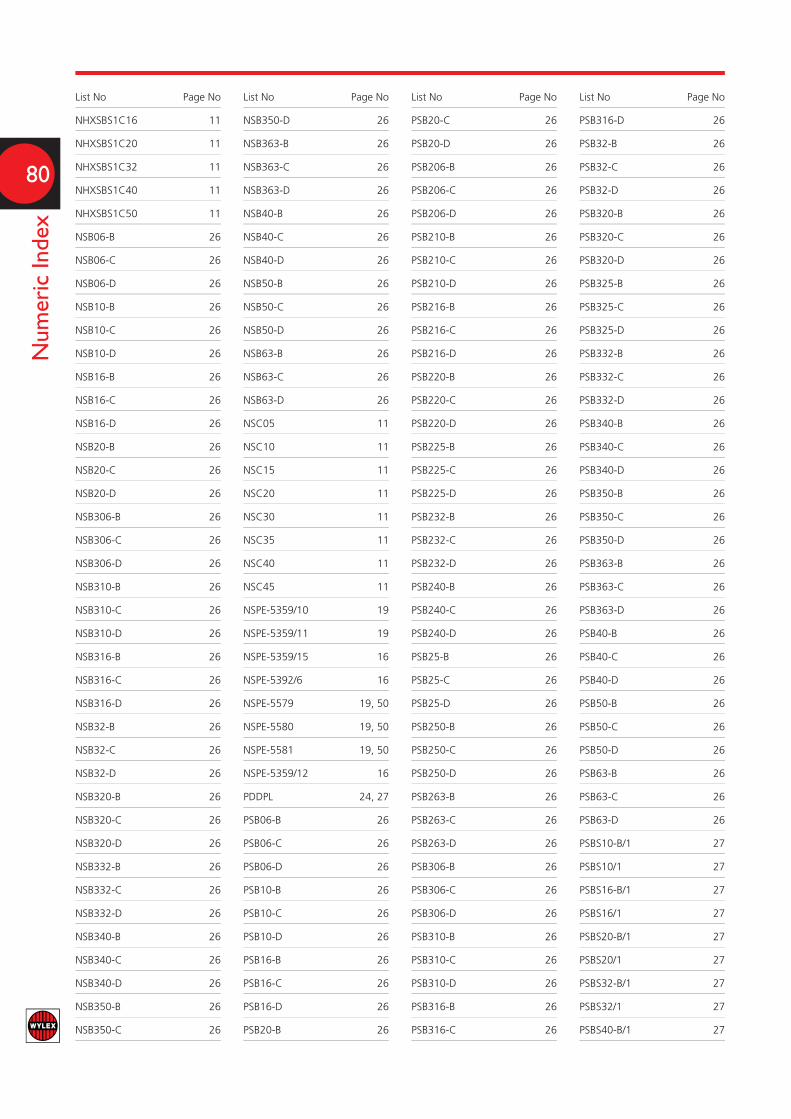
80
Numeric Index
List No Page No
NHXSBS1C16 11
NHXSBS1C20 11
NHXSBS1C32 11
NHXSBS1C40 11
NHXSBS1C50 11
NSB06-B 26
NSB06-C 26
NSB06-D 26
NSB10-B 26
NSB10-C 26
NSB10-D 26
NSB16-B 26
NSB16-C 26
NSB16-D 26
NSB20-B 26
NSB20-C 26
NSB20-D 26
NSB306-B 26
NSB306-C 26
NSB306-D 26
NSB310-B 26
NSB310-C 26
NSB310-D 26
NSB316-B 26
NSB316-C 26
NSB316-D 26
NSB32-B 26
NSB32-C 26
NSB32-D 26
NSB320-B 26
NSB320-C 26
NSB320-D 26
NSB332-B 26
NSB332-C 26
NSB332-D 26
NSB340-B 26
NSB340-C 26
NSB340-D 26
NSB350-B 26
NSB350-C 26
List No Page No
NSB350-D 26
NSB363-B 26
NSB363-C 26
NSB363-D 26
NSB40-B 26
NSB40-C 26
NSB40-D 26
NSB50-B 26
NSB50-C 26
NSB50-D 26
NSB63-B 26
NSB63-C 26
NSB63-D 26
NSC05 11
NSC10 11
NSC15 11
NSC20 11
NSC30 11
NSC35 11
NSC40 11
NSC45 11
NSPE-5359/10 19
NSPE-5359/11 19
NSPE-5359/15 16
NSPE-5392/6 16
NSPE-5579 19, 50
NSPE-5580 19, 50
NSPE-5581 19, 50
NSPE-5359/12 16
PDDPL 24, 27
PSB06-B 26
PSB06-C 26
PSB06-D 26
PSB10-B 26
PSB10-C 26
PSB10-D 26
PSB16-B 26
PSB16-C 26
PSB16-D 26
PSB20-B 26
List No Page No
PSB20-C 26
PSB20-D 26
PSB206-B 26
PSB206-C 26
PSB206-D 26
PSB210-B 26
PSB210-C 26
PSB210-D 26
PSB216-B 26
PSB216-C 26
PSB216-D 26
PSB220-B 26
PSB220-C 26
PSB220-D 26
PSB225-B 26
PSB225-C 26
PSB225-D 26
PSB232-B 26
PSB232-C 26
PSB232-D 26
PSB240-B 26
PSB240-C 26
PSB240-D 26
PSB25-B 26
PSB25-C 26
PSB25-D 26
PSB250-B 26
PSB250-C 26
PSB250-D 26
PSB263-B 26
PSB263-C 26
PSB263-D 26
PSB306-B 26
PSB306-C 26
PSB306-D 26
PSB310-B 26
PSB310-C 26
PSB310-D 26
PSB316-B 26
PSB316-C 26
List No Page No
PSB316-D 26
PSB32-B 26
PSB32-C 26
PSB32-D 26
PSB320-B 26
PSB320-C 26
PSB320-D 26
PSB325-B 26
PSB325-C 26
PSB325-D 26
PSB332-B 26
PSB332-C 26
PSB332-D 26
PSB340-B 26
PSB340-C 26
PSB340-D 26
PSB350-B 26
PSB350-C 26
PSB350-D 26
PSB363-B 26
PSB363-C 26
PSB363-D 26
PSB40-B 26
PSB40-C 26
PSB40-D 26
PSB50-B 26
PSB50-C 26
PSB50-D 26
PSB63-B 26
PSB63-C 26
PSB63-D 26
PSBS10-B/1 27
PSBS10/1 27
PSBS16-B/1 27
PSBS16/1 27
PSBS20-B/1 27
PSBS20/1 27
PSBS32-B/1 27
PSBS32/1 27
PSBS40-B/1 27

ELECTRIUM SALES LIMITED A SIEMENS COMPANYCommercial Centre, Lakeside Plaza, Walkmill Lane, Bridgtown, Cannock WS11 0XE.
eMail: [email protected] Web: www.electrium.co.uk
UK SALESTelephone: 01543 455020 Facsimile: 01543 455021 eMail: [email protected]
TECHNICALTelephone: 01543 438320 Facsimile: 01543 438321 eMail: [email protected]
EXPORT SALESTelephone: +44 1543 455049 Facsimile: +44 1543 455048 eMail: [email protected]
DUBAI OFFICETelephone: +971 4 3660687 Facsimile: +971 4 3660676 eMail: [email protected]
Although every effort has been made to ensure accuracy in the compilation of the technical detail within this publication, specifications and performance data are constantly changing. Latest details can be obtained from Wylex.
Publication No. WY2074a 12/12Printed in England.


