Domestic Refrigerated Container (DRC)120 Gallon Aluminum Fuel Tank
Installation InstructionsThese instructions are written exclusively for, and are limited to, the installation of the 120 gallon aluminum fuel tank (P/N 12-1001), positioned directly under a Thermo King Precedent C-600 RR, S-600 RR, S-600M RR, SB-230 RR or SB-330 RR refrigeration unit, and mounted onto the front wall of a Domestic Refrigerated Container (DRC) that was designed and built to meet the requirements specific to this application. All other installations are the responsibilities of the installer.
.
DANGER: All fuel tank mounting requirements detailed in this document must be met to correctly and safely install the 120 gallon tank onto the DRC. Failure to comply to these requirements could result in severe damage to equipment, injury or death!
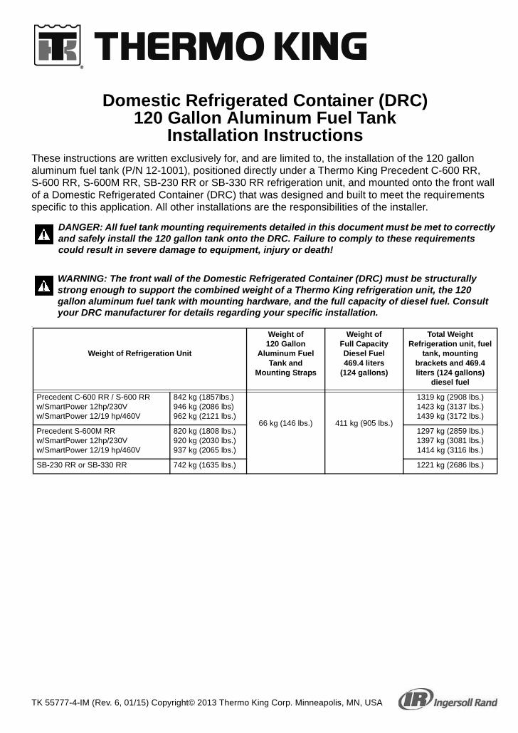
WARNING: The front wall of the Domestic Refrigerated Container (DRC) must be structurally strong enough to support the combined weight of a Thermo King refrigeration unit, the 120 gallon aluminum fuel tank with mounting hardware, and the full capacity of diesel fuel. Consult your DRC manufacturer for details regarding your specific installation.
Weight of Refrigeration Unit
Weight of 120 Gallon
Aluminum Fuel Tank and
Mounting Straps
Weight of Full Capacity Diesel Fuel 469.4 liters
(124 gallons)
Total Weight Refrigeration unit, fuel
tank, mounting brackets and 469.4 liters (124 gallons)
820 kg (1808 lbs.)920 kg (2030 lbs.)937 kg (2065 lbs.)
1297 kg (2859 lbs.)1397 kg (3081 lbs.)1414 kg (3116 lbs.)
SB-230 RR or SB-330 RR 742 kg (1635 lbs.) 1221 kg (2686 lbs.)
IMPORTANT DRC and 120 GALLON FUEL TANK REQUIREMENTS
IMPORTANT: Using the wrong fuel system fittings may void your engine warranty! All Thermo King supplied fuel line fittings (except fuel line connector) are nickel plated brass for Precedent units.
• DO NOT use fuel fittings (main body) made of brass, copper, zinc, zinc plated or galvanized steel where it would make direct contact with flowing diesel fuel. Diesel fuel flowing through these types of fittings allows those metals to leach into the fuel forming deposits on the injector tips which fouls them prematurely.
• Fuel fitting nuts, compression sleeves, and fuel line connectors made of brass are acceptable because diesel fuel does not flow across their surfaces.
• Do not use PTFE (Polytetrafluoroethylene) thread sealing tape on the fuel fittings in a Precedent unit. PTFE tape may allow strands into the fuel system that could plug up the tight clearance fuel injectors causing failures.
IMPORTANT: The factory installed fuel tank air vent must be in place and functional for the Thermo King unit’s fuel system to operate correctly and for the fuel tank to remain in compliance with Federal Motor Carrier Safety Administration specifications (title 49, paragraph 393.67). A plugged or restricted fuel tank air vent can result in premature damage to the fuel pump and could also cause severe damage to the fuel tank. NEVER remove or install any other component in place of the fuel tank air vent.
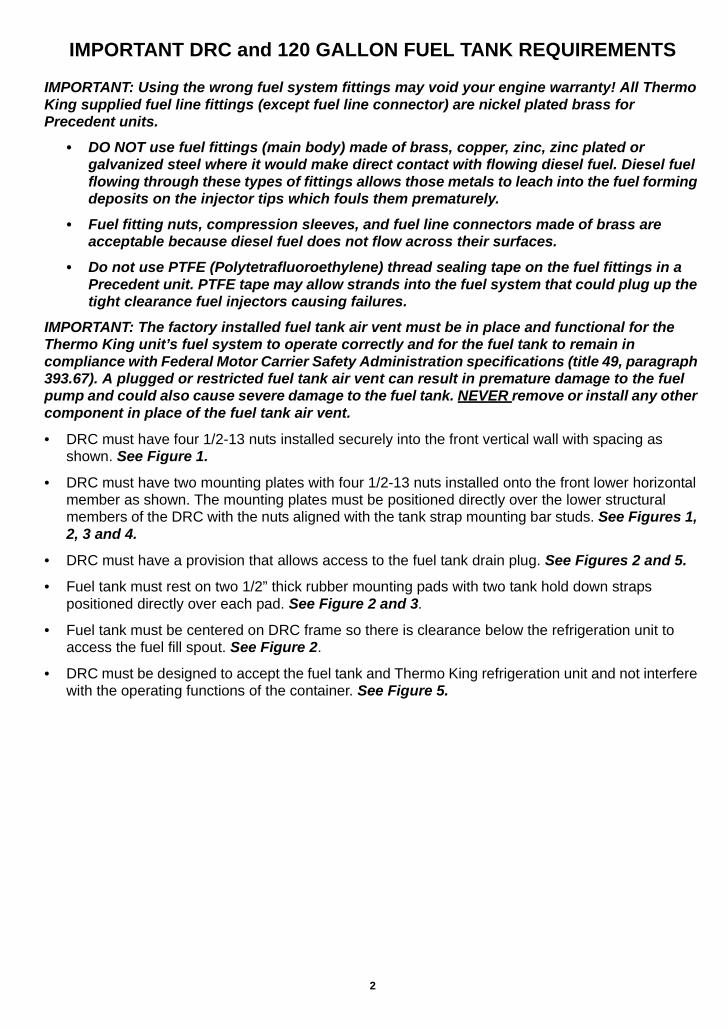
• DRC must have four 1/2-13 nuts installed securely into the front vertical wall with spacing as shown. See Figure 1.
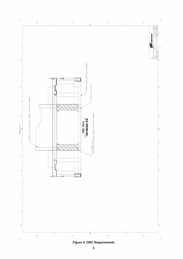
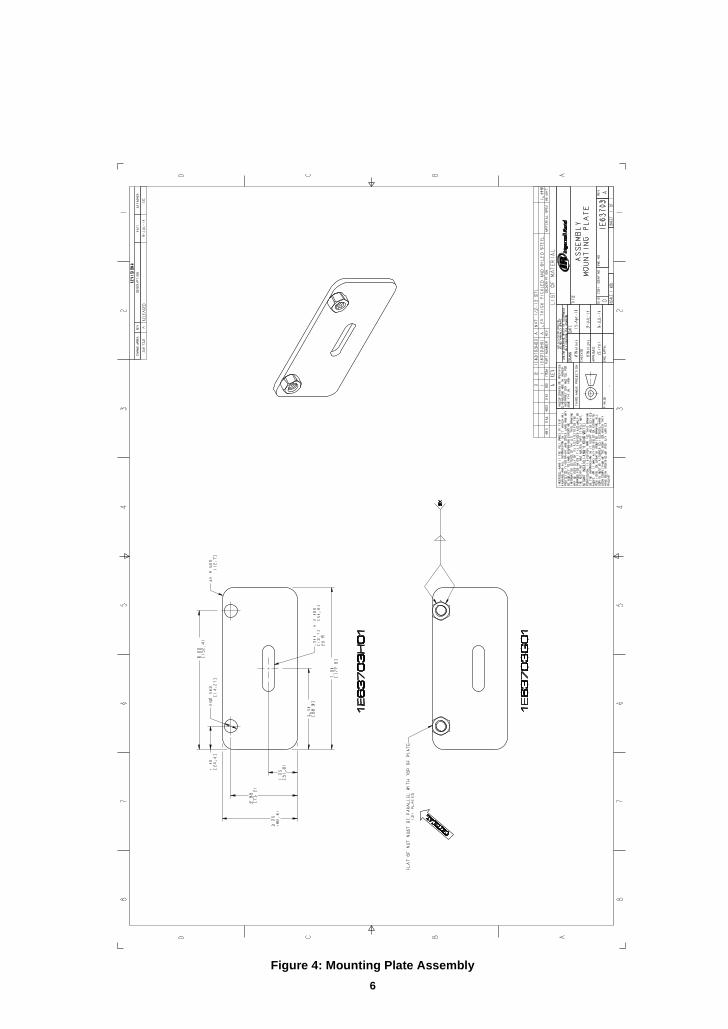
• DRC must have two mounting plates with four 1/2-13 nuts installed onto the front lower horizontal member as shown. The mounting plates must be positioned directly over the lower structural members of the DRC with the nuts aligned with the tank strap mounting bar studs. See Figures 1, 2, 3 and 4.
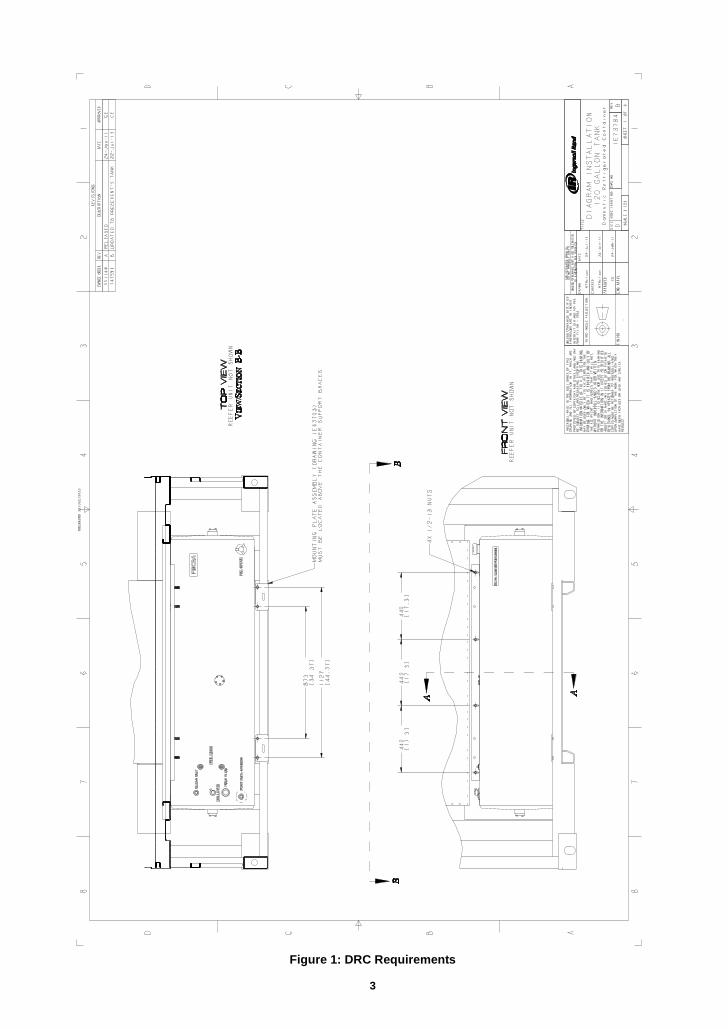
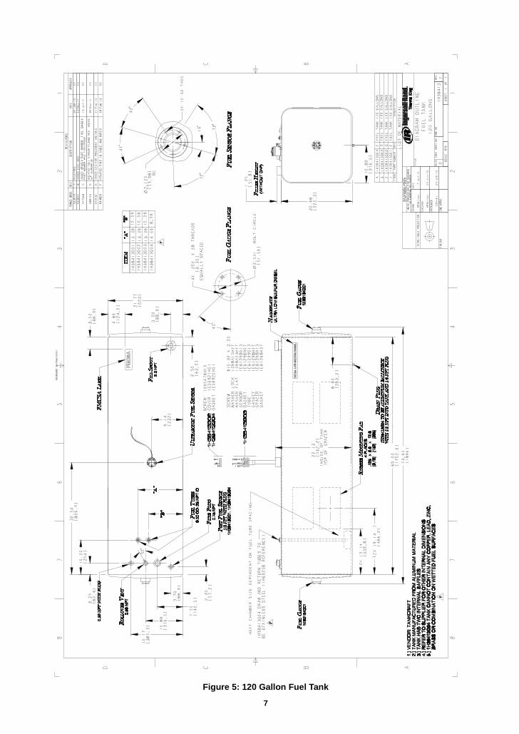
• DRC must have a provision that allows access to the fuel tank drain plug. See Figures 2 and 5.
• Fuel tank must rest on two 1/2” thick rubber mounting pads with two tank hold down straps positioned directly over each pad. See Figure 2 and 3.
• Fuel tank must be centered on DRC frame so there is clearance below the refrigeration unit to access the fuel fill spout. See Figure 2.
• DRC must be designed to accept the fuel tank and Thermo King refrigeration unit and not interfere with the operating functions of the container. See Figure 5.
2
Figure 1: DRC Requirements
RELEASED 30/Jul/2013
3
Figure 2: DRC Requirements
RELEASED 30/Jul/2013
4
Figure 3: DRC Requirements
RELEASED 30/Jul/2013
5
Figure 4: Mounting Plate Assembly
6
Figure 5: 120 Gallon Fuel Tank
RELEASED 28/Feb/2013
7
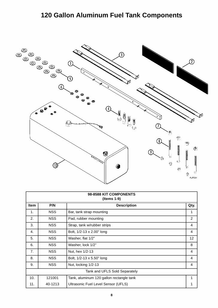
120 Gallon Aluminum Fuel Tank Components
98-8588 KIT COMPONENTS (Items 1-9)
Item P/N Description Qty.
1. NSS Bar, tank strap mounting 1
2. NSS Pad, rubber mounting 2
3. NSS Strap, tank w/rubber strips 4
4. NSS Bolt, 1/2-13 x 2.00” long 4
5. NSS Washer, flat 1/2” 12
6. NSS Washer, lock 1/2” 8
7. NSS Nut, hex 1/2-13 4
8. NSS Bolt, 1/2-13 x 5.50” long 4
9. NSS Nut, locking 1/2-13 4
Tank and UFLS Sold Separately
10.
11.
121001
40-1213
Tank, aluminum 120 gallon rectangle tank
Ultrasonic Fuel Level Sensor (UFLS)
1
1
8
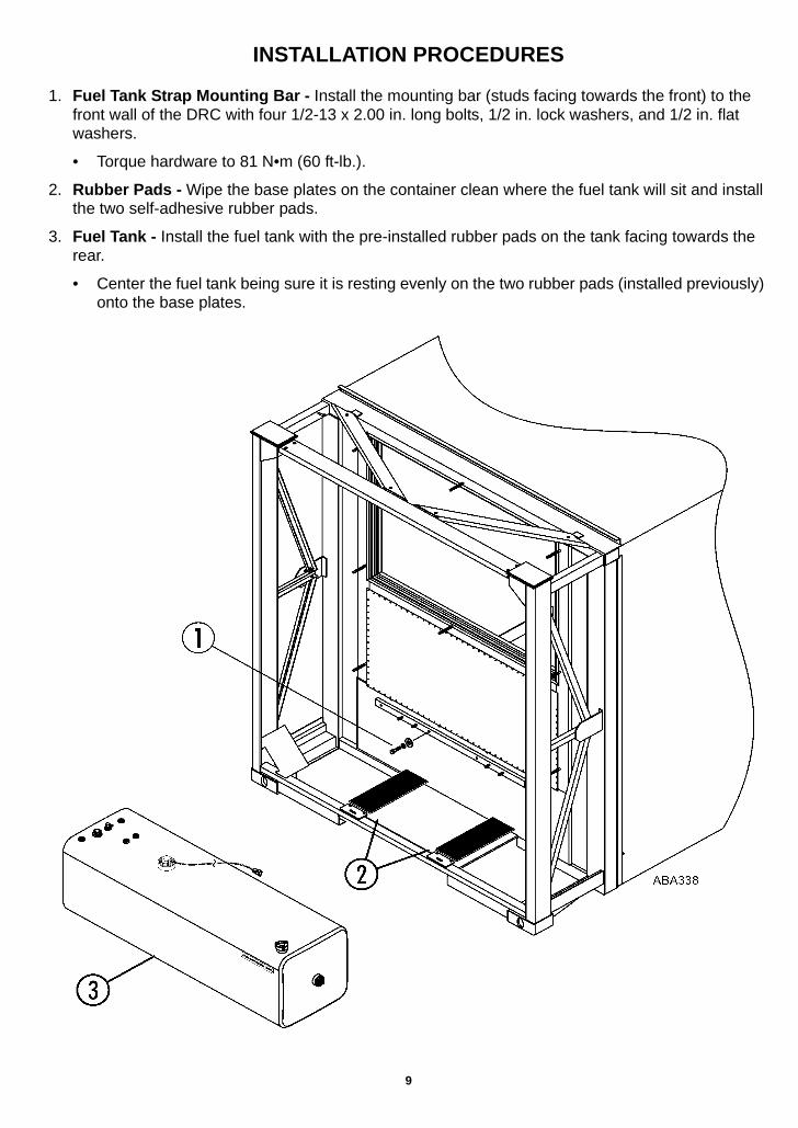
INSTALLATION PROCEDURES
1. Fuel Tank Strap Mounting Bar - Install the mounting bar (studs facing towards the front) to the front wall of the DRC with four 1/2-13 x 2.00 in. long bolts, 1/2 in. lock washers, and 1/2 in. flat washers.
• Torque hardware to 81 N•m (60 ft-lb.).
2. Rubber Pads - Wipe the base plates on the container clean where the fuel tank will sit and install the two self-adhesive rubber pads.
3. Fuel Tank - Install the fuel tank with the pre-installed rubber pads on the tank facing towards the rear.
• Center the fuel tank being sure it is resting evenly on the two rubber pads (installed previously) onto the base plates.
9
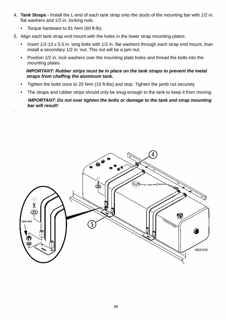
4. Tank Straps - Install the L-end of each tank strap onto the studs of the mounting bar with 1/2 in. flat washers and 1/2 in. locking nuts.
• Torque hardware to 81 N•m (60 ft-lb).
5. Align each tank strap end mount with the holes in the lower strap mounting plates:
• Insert 1/2-13 x 5.5 in. long bolts with 1/2 in. flat washers through each strap end mount, than install a secondary 1/2 in. nut. This nut will be a jam nut.
• Position 1/2 in. lock washers over the mounting plate holes and thread the bolts into the mounting plates.
IMPORTANT: Rubber strips must be in place on the tank straps to prevent the metal straps from chaffing the aluminum tank.
• Tighten the bolts once to 20 N•m (15 ft-lbs) and stop. Tighten the jamb nut securely
• The straps and rubber strips should only be snug enough to the tank to keep it from moving.
IMPORTANT: Do not over tighten the bolts or damage to the tank and strap mounting bar will result!
!
Jam Nut
10
FUEL LINE INSTALLATION
IMPORTANT: Using the wrong fuel system fittings may void your engine warranty!See “IMPORTANT DRC and 120 GALLON FUEL TANK REQUIREMENTS” on page 2.
6. Route the 3/8'' FUEL SUPPLY line from the fuel pump to the fuel tank fitting:
• The supply line when installed into the tank must be no higher than 25.4 mm (1.00 in.) from the bottom of the tank. Determine this length and cut the supply line.
• Cut the end of the supply line at a 45 degree angle and slide on the fuel line fittings.
• Insert the supply line into the fuel pickup fitting until it is 25.4 mm (1.00 in.) from the bottom of the tank then tighten the fuel line fitting securely.
7. Route the 1/4'' FUEL RETURN line from the fuel filter to the fuel tank:
• Cut the return line to the appropriate length and slide on the fuel line fittings.
• Install the line onto the fuel return fitting and then tighten the fuel line fitting securely.
8. Remove the plastic cap from the fuel vent and point the outlet to the rear of the container.
ULTRASONIC FUEL LEVEL SENSOR (UFLS)
Interconnect Harness Installation and Routing
IMPORTANT: All electrical connections of the UFLS harness must be made with the supplied crimp and solder style connectors with separate heat shrink tubing. DO NOT burn the heat shrink. If the heat shrink is burnt, charred, or has bubbles from overheating, the wire connections must be removed and redone correctly.
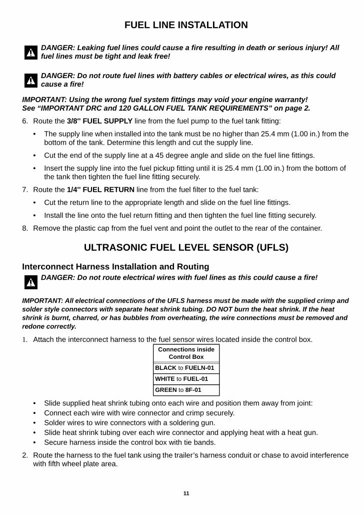
1. Attach the interconnect harness to the fuel sensor wires located inside the control box.
• Slide supplied heat shrink tubing onto each wire and position them away from joint:• Connect each wire with wire connector and crimp securely. • Solder wires to wire connectors with a soldering gun.• Slide heat shrink tubing over each wire connector and applying heat with a heat gun.• Secure harness inside the control box with tie bands.
2. Route the harness to the fuel tank using the trailer’s harness conduit or chase to avoid interference with fifth wheel plate area.
DANGER: Leaking fuel lines could cause a fire resulting in death or serious injury! All fuel lines must be tight and leak free!
DANGER: Do not route fuel lines with battery cables or electrical wires, as this could cause a fire!
DANGER: Do not route electrical wires with fuel lines as this could cause a fire!
Connections inside Control Box
BLACK to FUELN-01
WHITE to FUEL-01
GREEN to 8F-01
11
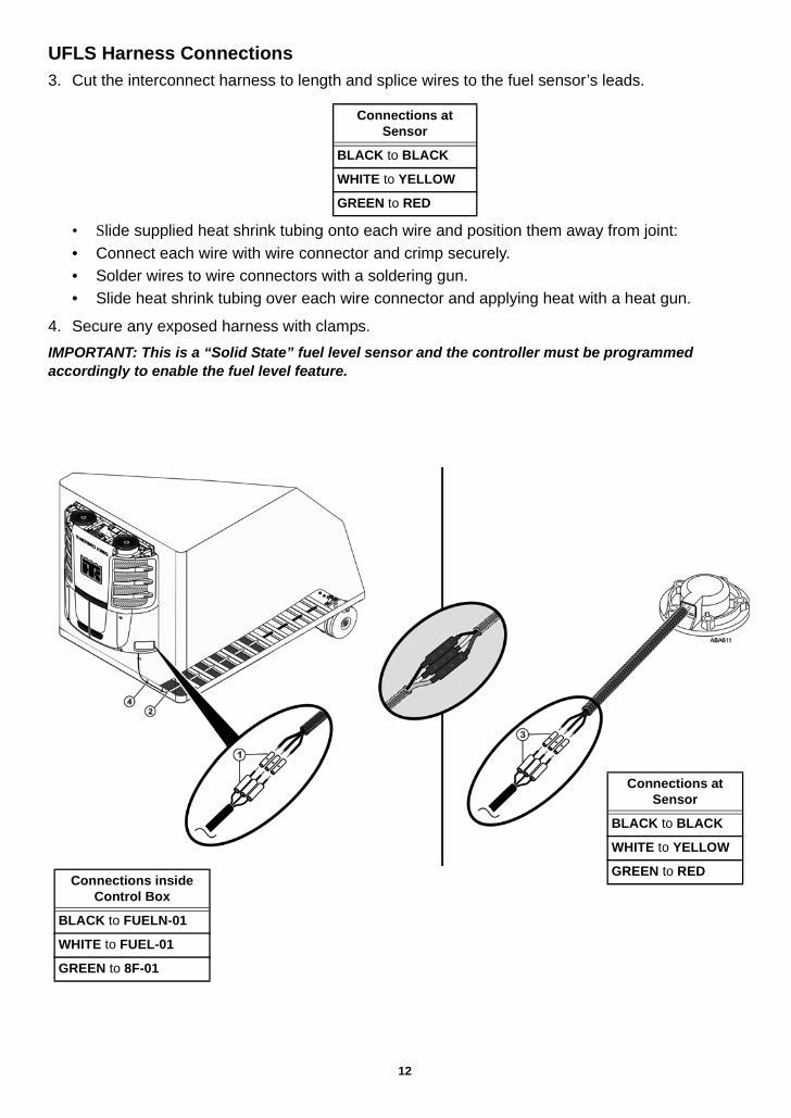
UFLS Harness Connections3. Cut the interconnect harness to length and splice wires to the fuel sensor’s leads.
• Slide supplied heat shrink tubing onto each wire and position them away from joint:• Connect each wire with wire connector and crimp securely. • Solder wires to wire connectors with a soldering gun.• Slide heat shrink tubing over each wire connector and applying heat with a heat gun.
4. Secure any exposed harness with clamps.
IMPORTANT: This is a “Solid State” fuel level sensor and the controller must be programmed accordingly to enable the fuel level feature.
Connections at Sensor
BLACK to BLACK
WHITE to YELLOW
GREEN to RED
Connections inside Control Box
BLACK to FUELN-01
WHITE to FUEL-01
GREEN to 8F-01
Connections at Sensor
BLACK to BLACK
WHITE to YELLOW
GREEN to RED
12
PROGRAMMING THE CONTROLLER FOR FUEL LEVELNOTE: These procedures can also be done through OptiSet™
1. Turn off the engine. (Guarded Access Menu is not available if the engine is running.)
2. Go to the Guarded Access Menu.
3. Scroll down to and select the Unit Configuration.
4. Scroll down to and select Fuel Level Sensor.
The choices are: NONE, SOLID STATE or FLOAT
• UFLS STYLE - scroll to SOLID STATE by pressing + key then YES key.
• FLOAT STYLE - scroll to FLOAT by pressing + key then YES key.
• Fuel Level Percent will now be in the gauge menu.