36
DOMINO - System For chemical liquids Flow measurement Dosing Filling Technical Information VD 5-111 E 12.2003

DOMINO - System
For chemical liquids
Flow measurementDosingFilling
Technical Information VD 5-111 E 12.2003

Technical Information
VD 5-111 E 2 Aquametro AG
Contents
6. PMD vane wheel flowmeters
6.1 Technical data 206.2 Materials 206.3 Pressure drop characteristics 206.4 Dimensions 216.5 RW roller registers, dials 216.6 Pulsers 216.7 Installation data for AS/ASP batching controls (see 5.3)6.8 Installation data for electronic batching controls (see 5.4)
7. DOMINO® pulsers
7.1 Industrial pulsers 227.2 Pulser integrated in roller register 22
8. Auxiliary units 23
9. System planning
9.1 Conceptual design 24-259.2 Pulsers / remote transmission 25-26
10. Accreditations
10.1 ATEX 2610.2 Pressure Equipment Directive PED 26
11. Data required for ordering
11.1 ARD sensors 27-2911.2 ARD modules 30-3111.3 AMD sensors 3211.4 AMD modules 3311.5 PMD meters 3411.6 ATEX modifications 3411.7 Accessories 34
1. Introduction
1.1 DOMINO®...the modular flow measurement concept 31.2 System overview 4-51.3 Product group overview 61.4 Applications and media 71.5 Operating principles 81.6 Design features 81.7 Measuring tolerances under reference conditions 9
2. ARD rotary piston flowmeters
Sensors (primary device)2.1 Technical data 102.2 Materials 112.3 Pressure drop characteristics 122.4 Dimensions 13
3. ARD rotary piston flowmeter
Modules (secondary device)3.1 RW, RV roller registers, dials 143.2 Pulsers 14-153.3 Installation data for AS/ASP batching controls 153.4 Installation data for electronic batching controls 15
4. AMD vane wheel flowmeter
Sensors (primary device)4.1 Technical data 164.2 Materials 164.3 Pressure drop characteristics 164.4 Dimensions 17
5. AMD vane wheel flowmeter
Modules (secondary device)5.1 RW, RV roller registers, dials 185.2 Pulsers 185.3 Installation data for AS/ASP batching controls 195.4 Installation data for electronic batching controls 19

Technical Information
Aquametro AG 3 VD 5-111 E
1. Introduction
1.1
DOMINO®...the modular flow measurement concept
Benefits
• Economical point of measurement lay-out• Customized systems for every application• Easy retroconversion by exchanging modules• Quality-certified to ISO 9001 / EN 29001
PMD
AMD
ARD

Technical Information
VD 5-111 E 4 Aquametro AG
1.2
Modules
Various modules according to application:• Roller registers• Reed-type pulsers or inductive
Auxiliary equipment
Filling control systems, flow computers, analogue signal generation
5.65558.4 AM066126.4
RWRoller register• local totalizing
RVRoller register with integralreed-type pulser• local totalizing• pulser for remote tota-
lizing• not for use in hazardous
areas!
INInductive pulser for in-dustrial control systems• to DIN 19234• 2 different resolutions• for explosion risk
zone 1• roller register
INAInductive pulser for in-dustrial control systems• to DIN 19234• high resolution for ana-
logue signal generationor input to electronicbatching controls
• for explosion riskzone 1
• optional roller register
AM066146.4AM066147.4
ARD rotary piston flowmeter forchemical liquids
AMD vane wheel flowmeter forchemical liquids
Modules (secondary device)
Flow sensors (primary device)
DOMINO®...for flow measurement, filling, dosing and process control
Measuring sensors
Three different ranges:• ARD rotary piston flowmeters for chemical liquids• AMD vane wheel flowmeters for chemical liquids• PMD vane wheel flowmeters primarily for water dosing
5.65569.4AM066133.4a

Technical Information
Aquametro AG 5 VD 5-111 E
Additional units
Mechanical batching control
AS or ASP modules• for explosion or non-explosion risk zones• AS type for manual control systems• ASP type for semi-automatic pneumatic control systems
Electronic batching control
Combination of INA pulser with any external batching control.
AM
06
61
38
.4
AM
06
61
39
.4
AM
06
61
66
.4
AM
06
61
67
.4
GTAS module
Intermediate drive forAS or ASP batching control
INA module
Pulsers forbatching controls
AM
066148.4
PMD vane wheel flowmeter for cold andhot water / dosing systems

Technical Information
VD 5-111 E 6 Aquametro AG
1.3
DOMINO®...product group summary
ARD rotary piston flowmeters for 10...30.000 l/h PMD vane wheel flowmeters for 100...20.000 l/h
• Nominal bore DN 15, 20, 25, 40 and 50 mm• Operating pressure PN 10, 16, 25 and 40 according to version• Media temperatures up to 180°C• Modular meter concept in various materials• Measuring error limits ± 0,5% of effective value• For high viscosity range up to about 10.000 mPa·s• Swivelling roller register for optimal readability• Special-purpose calibrations for differential pressure measurement
(optional)• All flowmeters available with various modules according to need
AMD vane wheel flowmeters for 140...12.000 l/h
• Nominal bore DN 25 and 40 with flanged connections• Operating pressure PN 25• Media temperatures up to 90°C, special versions up to 180°C• For low viscosity range up to 4 mPa·s• Measuring error limits ± 2% of effective value (± 5% at lower end of
measuring range)• All flowmeters available with various modules according to need
• Nominal bore DN 20, 25 and 40 with threaded connections• Operating pressure PN 16• Media temperatures up to 90°C• Primarily for water, also for non-aggressive low-viscosity fluids up to
4 mPa·s• Measuring error limits ± 2% of effective value (± 5% at lower end of
measuring range)• All flowmeters available with various modules according to need
VZTH 8 rotary piston flowmeter for 5...150 l/h
In addition to the DOMINO® range, a flowmeter is also available for lowerflows. For detailed technical data, please see our separate documenta-tion.
Main data:• Compact cubic design with tapped screw connections• Measuring sensor of brass and graphite or hard rubber, viton seals,
oil-resistant coloured plastic housing• Operating pressure PN 25• Media temperatures up to 90°C• Measuring error limits ± 1% of effective value• Roller register with glass cover for easy readability• Optional versions with reed-type sensor

Technical Information
Aquametro AG 7 VD 5-111 E
1.4
Applications
• ARD rotary piston flowmeters for pure chemical liquids of various types• AMD vane wheel flowmeters for chemical liquids• PMD vane wheel flowmeters for water (in particular for dosing)
Selection of commonly measured liquids
5-11
1e_1
Acetic acidAcetoneAnimal fatsAmmonium hydroxide, ammonia solutiuon
Bromium hydroxide, bromic acidButyl acetate, acetic butyl ester
Chloroform, trichloromethaneCitric acid
Diethylene glycolDistilled water
Ethyl acetate, acetic ether, acetic esterEthyl alcohol, alcohol, ethanolEthyl ethylene, ethylene, diethyl ethyleneEthylene glycol
Formaldehyde solutionFormic acid
Glycerine
HexineHydrochloric acidHydrofluoric acidHydrogen peroxide, hydrogen superoxide
Isopropyl ether, di-isopropyl etherIsopropyl alcohol, propyl alcohol
Kerosine, petroleum
Liquid ammoniaLiquid bromiumLiquid butane
Magnesium sulphateMethanol, methyl alcohol)Methylene chloride, dichloromethyleneMethyl ethyl ketoneMolasses (without urea)
Nitric acid
ParaffinPerchloroethylene, tetrachloroethylenePhosphoric acidPotassium hydroxide, caustic potashPropionic acidPrussic acidPure benzol
Sodium chloride solution, brineSodium hydroxide, caustic soda solutionSodium hypochlorite solution, Javelle waterSulfocarbonic acidSulphuric acid
Tar, pitchTetrachloromethane, carbon tetrachlorideTolueneTrichloroethylene (dry)
Vegetable oils
For fuel oil measurement the product range CONTOIL® is recommended.

Technical Information
VD 5-111 E 8 Aquametro AG
1.5
Operation principles
ARD range
• Works on the volumetric principle with rotary pistons• Wide measuring range with high precision• Suitable for high viscosities• Insensitive to flow disturbances• No power supply needed
5.65171.4
5.65028.4
5.65139.4
AMD and PMD series
• Works on the velocity measuring principle with multi-jet vane wheel• Extremely wide measuring range with good accuracy• Largely insensitive to slight impurities in liquid media• Insensitive to flow disturbances• No power supply needed
1.6
Design features
ARD range
• The only moving parts in contact with the liquid medium are the rotarypiston, guide rollers and carrier. The hydraulic measuring module iscompletely isolated from the roller register, and signals are transmit-ted magnetically through the sealed cover of the measuring chamber.
• For optimal readability, the roller register can be swivelled through360° on versions without RV integral pulser.
AMD and PMD series
• The only moving part in contact with the liquid medium is the vanewheel. In AMD models this is mounted between PTFE bearings, and inPMD models on ruby bearings. This ensures years of easy running andhigh precision, long life and excellent long-term stability of themeasuring characteristic.
• The hydraulic measuring module is completely isolated from the rollerregister, and signals are transmitted magnetically through the sealedcover of the measuring chamber.
• For optimal readability, the roller register can be swivelled through360° on versions without RV integral pulser.
AM066168.4 AM066169.4
Technical Information
Aquametro AG 9 VD 5-111 E
1.7
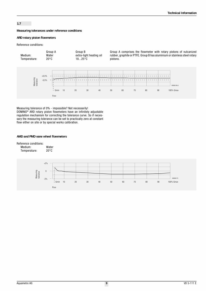
Measuring tolerances under reference conditions
ARD rotary piston flowmeters
Reference conditions:
Group A Group BMedium: Water extra-light heating oilTemperature: 20°C 18...25°C
Group A comprises the flowmeter with rotary pistons of vulcanizedrubber, graphite or PTFE. Group B has aluminium or stainless steel rotarypistons.
Measuring tolerance of 0% - impossible? Not necessarily!DOMINO® ARD rotary piston flowmeters have an infinitely adjustableregulation mechanism for correcting the tolerance curve. So if neces-sary the measuring tolerance can be set to practically zero at constantflow either on site or by special works calibration.
AM066196.4
10 20 30 40 50 60 70 80 90 100% QmaxQmin
Flow
Mea
suri
ng
tole
rance
+0,5%
-0,5%
AM066170
Flow
Mea
suri
ng
tole
rance
-2%
+2%
0
10 20 30 40 50 60 70 80 90 100% QmaxQmin
AMD and PMD vane wheel flowmeters
Reference conditions:Medium: WaterTemperature: 20°C
Technical Information
VD 5-111 E 10 Aquametro AG
1) Overall lengh with PTFE housings is 260 mm2) Flows with heating oil are higher. For precise data see "Technical Information VD 4-411",
CONTOIL VZO oil flowmeter3) Qmin and starting flows are valid for material pairing: brass housing / aluminium pistons and
EL heating oil as medium. Qmin for other material pairings is given in the table below:"Measuringrange as a function of material pairing".
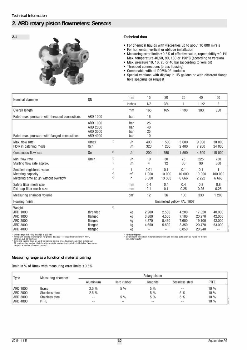
Measuring range as a function of material pairing
Qmin in % of Qmax with measuring error limits ±0.5%
5-11
1e_2
5-11
1e_3
4) For roller register.5) Meter weight depends on material combinations and modules. Data given are typical for meters
with roller register
epyT rebmahcgnirusaeM notsipyratoR
muinimulA rebburdraH etihparG leetssselniatS EFTP
0001DRA0002DRA0003DRA0004DRA
ssarBleetssselniatSleetssselniatS
EFTP
%5.2%5.2
----
%5--%5--
%5%5%5--
--%5%5--
%01%01%01%01
retemaidlanimoN ND mm 51 02 52 04 05
sehcni 2/1 4/3 1 2/11 2
htgnelllarevO mm 561 561 )1 091 003 053
snoitcennocdedaerhthtiwerusserp.xamdetaR 0001DRA rab 61
snoitcennocdegnalfhtiwerusserp.xamdetaR
0001DRA0002DRA0003DRA0004DRA
rabrabrabrab
52045201
etarwolf.xaMedomgnihctabniwolF
xamQhcQ
)2 h/lh/l
004023
00510021
00030042
00090027
0000300042
etarwolfsuounitnoC nQ )2 h/l 002 057 0051 0054 00051
etarwolf.niM.xorppaetarwolfgnitratS
nimQ )3
)3h/lh/l
014
0321
5703
52209
057003
eulavderetsigertsellamSyticapacgnireteM
wolfrevotuohtiwnQtaemitgnireteM
)4
)4
)4
lm3
h
10.000010005
1.00000133331
1.000001
6666
1.000001
2222
1000001
6666
ezishsemretlifytefaSezishsemretlifparttriD
mmmm
4.01.0
4.01.0
4.052.0
8.052.0
8.052.0
emulovrebmahcgnirusaeM mc 3 21 63 001 033 0021
hsinifgnisuoH 7001LARwolleydellemanE
thgieW0001DRA0001DRA0002DRA0003DRA0004DRA
dedaerhtdegnalfdegnalfdegnalfdegnalf
)5
gkgkgkgkgk
002.2008.3073.4056.4
--
005.2005.4084.5008.5
--
002.4001.7006.7053.8058.8
023.71072.02001.91074.02042.02
000.04000.24000.24000.35
--
Technical data
• For chemical liquids with viscosities up to about 10 000 mPa·s• For horizontal, vertical or oblique installation• Measuring error limits ±0.5% of effective value, repeatability ±0.1%
Max. temperature 40,50, 90, 130 or 190°C (according to version)• Max. pressure 10, 16, 25 or 40 bar (according to version)• Threaded connections (brass housing)• Combinable with all DOMINO® modules• Special versions with display in US gallons or with different flange
hole spacings on request
2. ARD rotary piston flowmeters: Sensors
2.1

Technical Information
Aquametro AG 11 VD 5-111 E
epyT tnenopmoC lairetaM
0001DRAgnisuoH
rebmahcgnirusaeMslaeS
snotsipyratoR
)snoitcennocegnalfrodedaerht(noritsaccitilorehpsro)snoitcennocdedaerht(ssarB031(SPP/ssarB ° 081(EFTP/ssarbro)C ° )C
)remotsaleoroulf(MPFEFTProetihparg,rebburdrah,muinimulA
0002DRAgnisuoH
rebmahcgnirusaeMslaeS
snotsipyratoR
noritsaccitilorehpS031(SPP/*leetssselniatS ° 081(EFTP/*leetssselniatsro)C ° )C
)enelyhteoroulfartetyloproremotsaleoroulf(EFTProMPFEFTPro*leetssselniats,etihparg,muinimulA
0003DRAgnisuoH
rebmahcgnirusaeMslaeS
snotsipyratoR
*leetssselniatSEFTP/*leetssselniatS
)enelyhteoroulfartetyloproremotsaleoroulf(EFTProMPFEFTPro*leetssselniats,etihparg,rebburdraH
0004DRAgnisuoH
rebmahcgnirusaeMslaeS
snotsipyratoR
gniveelslatemhtiw,EFTPgniveelslatemhtiw,latnaT/EFTP
)remotsaleoroulfreP(MKFFEFTP
2.2
ARD measuring sensors and materials
5-11
1e_4
* Corrosion and acid-resistant steel (CrNiMo) to DIN 1.14408 / 1.4435

Technical Information
VD 5-111 E 12 Aquametro AG
2.3
ARD pressure drop curves
Recommended pressure drop max. 1 barAdmissible pressure drop max. 3 bar
Viscosities:
A = 4.5 mPa·sB = 25 mPa·sC = 50 mPa·sD = 100 mPa·sE = 200 mPa·sF = 500 mPa·sG = 1000 mPa·sH = 2000 mPa·sI = 5000 mPa·s
I
H
F
G
B
C
D
E
A
Flow in l/h
Pre
ssu
red
rop
inm
bar
DN 15
5.65412.4
3 000
1 000
100
10
1
1 10 100 1 000 l/h
Qmax 400 l/hQmin 10 l/h
0.1
Flow in l/h
3 000
1 000
Pre
ssure
dro
pin
mbar
I
H
F
G
C
D
E
A
5.65413.4
10 100 1 000 10 000 l/h
Qmin 30 l/h Qmax 1 500 l/h
100
10
1
0.1
DN 20
Flow in l/h
3 000
0.1
10
100
1 000
Pre
ssu
red
rop
inm
bar
DN 25
I
H
F
G
C
D
E
A5.65414.4
10 100 1 000 10 000 l/h
Qmax 3 000 l/hQmin 75 l/h
1
100 000 l/hFlow in l/h
3 000
0.1
1
10
100
1 000
Pre
ssu
red
rop
inm
bar
DN 40
Q min 225 l/h Q max 9 000 l/h
I
H
F
G
C
D
E
A
5.65415.4
100 1 000 10 000
100 000 l/hFlow in l/h
3 000
0.1
10
100
1 000
Pre
ssu
red
rop
inm
bar
DN 50
Q max 30 000 l/h
I
H
F
G
C
D
E
A
5.65416.4
1
100 1 000 10 000
Qmin 750 l/h

Technical Information
Aquametro AG 13 VD 5-111 E
2.4
ARD flowmeter unit dimensions
ARD 1000 with threaded connections
DN 15, 20, 25 DN 40, 50
ARD 1000, 2000, 3000 with flanged connections (to DIN 2501)
DN 15, 20, 25 DN 40, 50
øf AM066158.4
r
d AM066157.4
bc
a
p
ARD 4000 with flanged connections (to DIN 2501 / SN 21843)
DN 25
øf AM066156.4
øf1
a
bc
AM066155.4 øf AM066162.4
øf1
a
bc
AM066161.4
ND a b c fØ 1fØ
52DRA04DRA
5204
062003
701751
3253
061212
511051
øf1
a
bc
AM066151.4 øf AM066154.4
øf1
a
bc
AM066153.4
ND a b c d fØ 1fØ p r
51DRA02DRA52DRA04DRA05DRA
5102520405
561561091003053
244587611661
7171122383
062062503044015
501501031012082
59501511051561
"4/3G"1G
"4/11G"2G
"8/32G
"2/1G"4/3G
"1G"2/11G
"2G
DN 40
AM066160.4øf
p
a
cb
AM
06
61
59
.4
r
d
5-11
1e_5
5-11
1e_6
Technical Information
VD 5-111 E 14 Aquametro AG
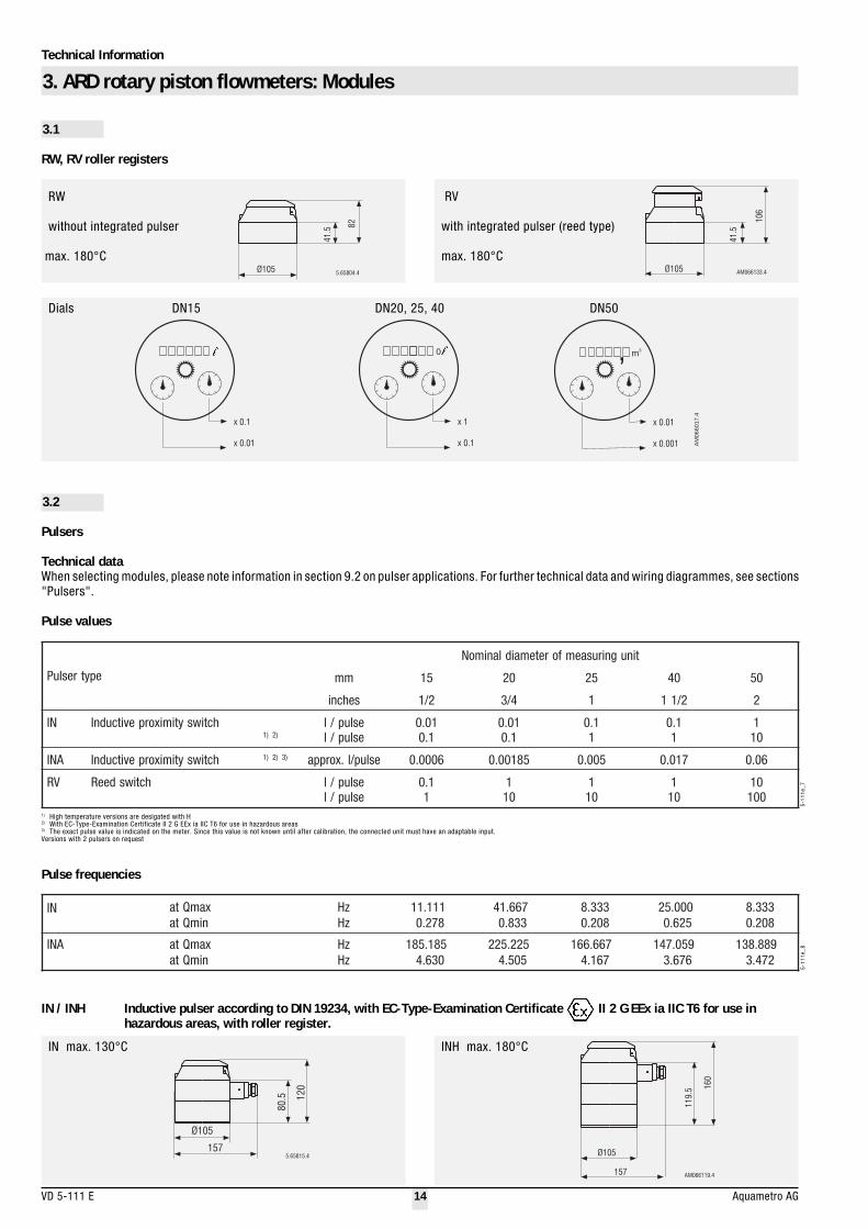
3. ARD rotary piston flowmeters: Modules
3.1
RW, RV roller registers
epytresluP
tinugnirusaemforetemaidlanimoN
mm 51 02 52 04 05
sehcni 2/1 4/3 1 2/11 2
NI hctiwsytimixorpevitcudnI)1 )2
eslup/leslup/l
10.01.0
10.01.0
1.01
1.01
101
ANI hctiwsytimixorpevitcudnI )1 )2 )3 eslup/l.xorppa 6000.0 58100.0 500.0 710.0 60.0
VR hctiwsdeeR eslup/leslup/l
1.01
101
101
101
01001
41.5
82
Ø105 5.65804.4Ø105
106
41.5
AM066133.4
x 0.1
x 0.01
x 1
x 0.1
m3,
x 0.01
x 0.001 AM
0660
17.4
0
RV
with integrated pulser (reed type)
max. 180°C
3.2
Pulsers
RW
without integrated pulser
max. 180°C
1) High temperature versions are desigated with H2) With EC-Type-Examination Certificate II 2 G EEx ia IIC T6 for use in hazardous areas3) The exact pulse value is indicated on the meter. Since this value is not known until after calibration, the connected unit must have an adaptable input.Versions with 2 pulsers on request
Pulse frequencies
IN / INH Inductive pulser according to DIN 19234, with EC-Type-Examination Certificate II 2 G EEx ia IIC T6 for use inhazardous areas, with roller register.
5.65815.4
Ø105
157
12
0
80
.5
160
119.5
Ø105
157 AM066119.4
5-11
1e_7
5-11
1e_8
Dials DN15 DN20, 25, 40 DN50
Technical dataWhen selecting modules, please note information in section 9.2 on pulser applications. For further technical data and wiring diagrammes, see sections"Pulsers".
Pulse values
NI xamQtanimQta
zHzH
111.11872.0
766.14338.0
333.8802.0
000.52526.0
333.8802.0
ANI xamQtanimQta
zHzH
581.581036.4
522.522505.4
766.661761.4
950.741676.3
988.831274.3
IN max. 130°C INH max. 180°C

Technical Information
Aquametro AG 15 VD 5-111 E
INA / INAH Inductive pulsers according to DIN 19234, with high resolution, with EC-Type-Examination Certificate II 2 G EEx iaIIC T6 for use in hazardous areas
Ø105
157
148
41.5
5.65818.4
55.5
Ø105
157 56
58
09
.4
Ø105
157
18
8
80
.5
AM066130.4
Ø105
157
94
.55.6
5808.4
without RW (roller register)
INA
max. 90°C
with RW (roller register)
INAH
3.3
Ø105
39
5.65807.4
26
8A
M0
66
14
0.4
360º
250
16090
30
6
250
360
AM
066141.4
90 160
30
6
250 AM
066143.4
360º
90 160
GTAS with dosing control (optional)
For technical data on AS / ASP batching control modules see separate documentation
AM
066177.4
3.4
Installation data for AS / ASP mechanical batching controls
max. 180°C GTAS module
for AS / ASP with AS 110, 120 all other AS with ASP
Installation possibilities for external electronic batching controls
max. 90°C INA / RD.. recommended (others also possible)max. 180°C INAH / RD.. recommended (others also possible)
AM06
6178
.4
max. 180°Cmax. 90°C
max. 180°C
Wall mounting Panel mounting

Technical Information
VD 5-111 E 16 Aquametro AG
4.3
AMD pressure drop characteristics
DN mm
1000
100
10
1
Pre
ssu
red
rop
inm
bar
0.1 1 10 100
Flow in m3/h
25 40
AM066179.4
tnenopmoC lairetaM
gnisuoHtinugnirusaeM
slaeSsgniraebleehwenaV
*leetssselniatS*leetssselniatS
EFTP09(EFTP ° 081(etihparg,)C ° )C
5-11
1e_9
5-11
1e_1
0
retemaidlanimoN ND mm 52 04
sehcni 1 2/11
htgnelllarevO mm 561 003
NPerusserpdetaR rab 52 52
erutarepmet.xaM xamT °C 081.pser09
etarwolf.xaM xamQ h/l 0005 00021
etarwolfsuounitnoC nQ h/l 0053 00001
etarwolflanoitisnarTetarwolf.niM
:lortnocgnillif011SAhtiWetarwolflanoitisnarT
etarwolf.niM
tQnimQ
tQnimQ
h/lh/l
h/lh/l
082041
053012
008004
0001006
eulavderetsigertsellamSyticapacgnireteM
wolfrevotuohtiwnQtaemitgnireteM
lm3
h.xorppa
1.0000001
00582
1.000000100001
esabretemniezishsemretlifytefaS mm 5.2 5.2
hsinifgnisuoH 7001LARwolleydellemanE
thgieW gk.xorppa 2.7 2.41
4. AMD vane wheel flowmeters: Sensors
4.1 Technical data
• For chemical liquids with viscosities up to about 4 mPa·s• For horizontal installation - dial upward• Measuring error limits ±2% of effective value 1), repeatability ±0.3%• Temperature 90°C, 180°C• Rated pressure PN 25• Housing with flanged connections to DIN 2501 / SN 218643• Combinable with all DOMINO® modules• Special versions with other flange holes on request
1) ± 5% at lower end of measuring range between Qmin and Qt
4.2
AMD measuring module materials
*) Corrosion and acid-resistant steel (CrNiMo) to DIN 1.4408 / 1.44354

Technical Information
Aquametro AG 17 VD 5-111 E
11
5
165
66
61
12
7
AM066180.4
115AM066181.4
Ø150
300
83
81
164
AM066182.4
190 110
Ø138AM066183.4
4.4
AMD measuring module dimensions
AMD 25
AMD 40
Flanges to DIN 2501 / SN 21843

Technical Information
VD 5-111 E 18 Aquametro AG
5. AMD vane wheel flowmeters: Modules
5.1
RW, RV roller register
5.2
Pulsers
Technical data
Ø105
157
41
.5
82
AM066123.4
55.5
Ø105
157 565809.4
Ø105
157
94
.55.6
5808.4
INA, max. 90°C INAH, max. 180°CIN, max. 130°C
5-11
1e_1
1b
When selecting modules, please note information in section 9.2 on pulser applications. For further technical data and wiring diagrammes see sections"Pulsers".
Pulse values
1) With EC-Type-Examination Certificate II 2 G EEx ia IIC T6 for use in hazardous areas2) High temperature versions are designated with H
Pulse frequencies
IN pulser module
IN inductive pulser, according to DIN 19234, with EC-Type-Examination Certificate II 2 G EEx ia IIC T6 for use inhazardous areas
epytresluP )2
tinugnirusaemforetemaidlanimoN
mm 52 04
sehcni 1 2/11
VRNI
hctiwsdeeRhctiwsytimixorpevitcudnI )1
eslup/leslup/leslup/l
11.0
1
11.0
1
ANI hctiwsytimixorpevitcudnI )1 eslup/l.xorppa 23010.0 65930.0
1.0NI xamQtanimQta
zHzH
555.31983.0
333.33111.1
ANI xamQtanimQta
zHzH
285.431867.3
062.48908.2
5-11
1e_1
1a
41.5
82
Ø105 5.65804.4
m3,
x 0.01x 0.001x 0.0001AM066145.4
RW, max. 180° Cwithout integral pulser
Dials DN 25, 40
Ø105
106
41.5
AM066133.4
RV, max. 180° Cwith integral reed-type pulser
INA/INAH pulser modules
High resolution INA inductive pulser according to DIN 19234, with EC-Type-Examination Certificate II 2 G EEx ia IIC T6 for use inhazardous areas
Technical Information
Aquametro AG 19 VD 5-111 E
Ø105
39
5.65807.4
268
AM
06
61
40
.4
360º
250
16090
30
6
250
360
AM
06
61
41
.4
90 160
30
6
250 AM
066143.4
360º
90 160
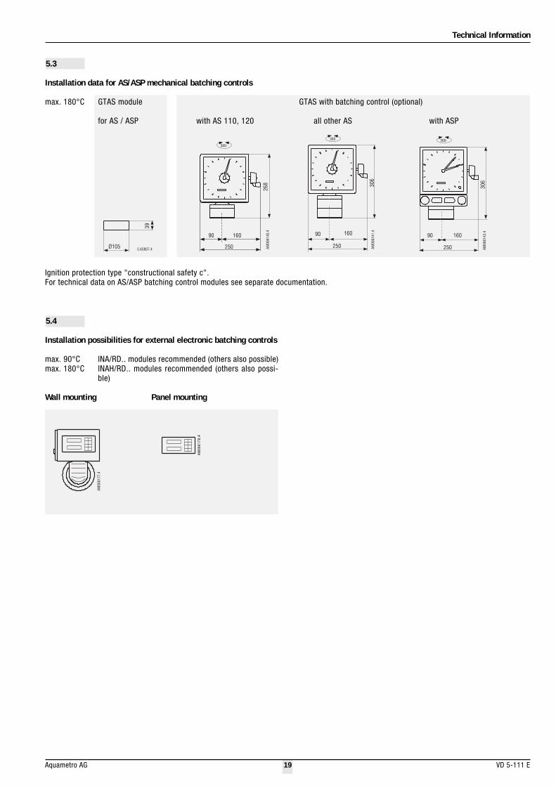
5.3
Installation data for AS/ASP mechanical batching controls
max. 180°C GTAS module
for AS / ASP with AS 110, 120
GTAS with batching control (optional)
all other AS with ASP
Ignition protection type "constructional safety c".For technical data on AS/ASP batching control modules see separate documentation.
5.4
Installation possibilities for external electronic batching controls
max. 90°C INA/RD.. modules recommended (others also possible)max. 180°C INAH/RD.. modules recommended (others also possi-
ble)
AM
066177.4
AM06
6178
.4
Wall mounting Panel mounting

Technical Information
VD 5-111 E 20 Aquametro AG
6. PMD vane wheel flowmeters
6.1 Technical data
• Primarily used for water flow measurement or dosing• Brass housing with threaded connections or threaded flanges• For horizontal installation - dial upward• Measuring tolerances ± 2% of effective value 1), repeatability ± 0.3%• Temperature max. 90°C• Rated pressure 16 bar• Available only with modules "pulser with roller register" or "installa-
tion for batching control".
1) ± 5% at lower end of measuring range between Qmin and Qt
6.2
PMD materials
6.3
PMD pressure drop characteristics
tnenopmoC slairetaM
gnisuoHtinugnirusaeM
laeSleehwenaV
ssarBcitsalpOPP
)enelyporpenelyhte(MDPEsllabyburcitehtnysdnacitsalP
AM06
6184
.4
DN mm 20 25 40
1 000
100
10
1
0.1 1 10 100
Pres
sure
dro
p in
mba
r
Flow in m /h3
5-11
1e_1
2
5-11
1e_1
3
retemaidlanimoN ND
mm 02 52 04
sehcni 4/3 1 2/11
htgnelllarevO mm 091 062 003
erusserpdetaR NP rab 61
erutarepmet.xaM °C 09
etarwolf.xaM xamQ h/l 0005 0007 00002
etarwolfsuounitnoC nQ h/l 0052 0053 00001
etarwolflanoitisnarTetarwolf.niM
:lortnocgnillif011SAhtiWetarwolflanoitisnarT
etarwolf.niM
tQnimQ
tQnimQ
h/lh/l
h/lh/l
002001
053052
082041
054003
008004
0001006
eulavderetsigertsellamSyticapacreteM
wolfrevotuohtiwnQtaemitgnireteM
lm3
h.xorppa
1.000000100004
1.000000100582
1.000000100001
esabretemniezishsemretlifytefaS mm 5.1 5.1 5.2
daerhtgnisuoHdaerhtnoitcennocwercS
sehcnisehcni
14/3
4/111
22/11
hsinifgnisuoH 7001LARwolleydellemanE
snoitcennocwercstuohtiwthgieW gk 1.3 1.4 5.6

Technical Information
Aquametro AG 21 VD 5-111 E
Technical data
When selecting modules, please note information in section 9.2 on pulser applications. For further technical data and wiring diagrammes see sections"Pulsers".
Pulse values
1) With EC-Type-Examination Certificate II 2 G EEx ia IIC T6 for use in hazardous areas
Pulse frequencies
6.4
PMD measuring module dimensions
ØfA
M0
66
18
6.4
r
Øf1
a
d
cb
p
AM
066185.4
m3,
x 0.01x 0.001x 0.0001AM066145.4
6.6
Pulsers
6.7
Installation data for AS/ASP mechanical batching controls
Same specifications and dimensions as for AMD. See section 5.3.
Same specifications and dimensions as for AMD. See section 5.2.
6.8
Installation data for electronic batching controls
Same specifications and dimensions as for AMD. See section 5.4.
5-11
1e_1
45-
111e
_15a
6.5
PMD roller register
Dials DN 20, 25 and 40
Module installation heights are given in sections "AMD modules".
NDmm
amm
bmm
cmm
dmm
fØmm
1fØmm
p r
02DMP52DMP04DMP
025204
091062003
730406
473819
582573044
29501931
501511051
"1G"4/11G
"2G
"4/3G"1G
"2/11G
epytresluPtinugnirusaemforetemaidlanimoN
mm 02 52 04
sehcni 4/3 1 2/11
NI hctiwsytimixorpevitcudnI )1 eslup/leslup/l
1.01
1.01
1.01
ANI hctiwsytimixorpevitcudnI )1 eslup/l.xorppa 46800.0 43410.0 09940.0
NI xamQtanimQta
zHzH
888.31872.0
444.91983.0
555.55111.1
ANI xamQtanimQta
zHzH
157.061512.3
695.531217.2
433.111722.2
5-11
1e_1
5b

Technical Information
VD 5-111 E 22 Aquametro AG
+/-
+/-
5.65078.4
Ri 47 Ohm
7. DOMINO® pulsers
Technical data for industrial pulsers
IN Inductive pulser with decadic pulse valuesINA High-resolution inductive pulser
Switching element Slotted disc initiator according toDIN 19234
Switching voltage 5...15 VDCResidual ripple max. 5%
Switching current > 3 mA (at 8 VDC, 1KOhm)Static current < 1 mA (at 8 VDC, 1 KOhm)Switch-on time 50 ± 10%
Ambient temperature -10 ... +70°CProtection class IP 65 according to IEC 144 (protection
against water jets and dust)Use in explosion risk zones With EC-Type-Examination Certificate
II 2 G EEx ia IIC T6 for use in hazardousareas
Connection Connect cabel (min. 2 x 0.35 mm2) topulser probe with plug provided.Cable outer diameter 4...6 mm.For use in explosion risk zones are pref-erably light blue cables to be used. Seelocal regulations for Ex risk use!
7.1
AM066211b.4
+
-
Wiring diagramme
7.2
Wiring diagramme
Pulser types IN, INAfor industrial applications
IN, INA pulser module
Technical data for pulser integrated in roller register
RV Reed pulser with decadic pulse values
This simple version of a reed pulser is suitable for remote totalizing.For industrial control systems the IN or INA versions are recomended.Electronic pulse counters have low switching power consumption. Theyare therefore energized directly from the pulser. Electromechanicalpulse counters with power consumption exceeding 2 W require anintermediate switching relay (e.g. WE 77).
Switching element Reed contact tube filled with inert gasSwitching voltage max. 48 V AC or DCSwitching current max. 50 mA (internal resistance 47 Ohm/
0.5 W)Static current open contactSwitching power max. 2 W
Ambient temperature -10 ... +70°CProtection class IP 65 according to IEC 144 (protection
against water jets and dust)Connection Permanent mounted grey cable, 3m
long, 2 x 0.14 mm2 cross section
RV pulser for remote totalizingintegrated in roller register

Technical Information
Aquametro AG 23 VD 5-111 E
8. Auxiliary units
AS / ASP mechanical batching controls
• For explosion-protected or non-Ex.-protected zones• AS type for manual controls• ASP type for semi-automatic pneumatic controls
Electronic batching controls
Combination of INA pulser with any external batching control.

Technical Information
VD 5-111 E 24 Aquametro AG
9. System planning
9.1
Conceptual design
Piping layout
All meters and modules should be easily accessible for reading.
Do not install meters facing downwards. Straight piping for flowstabilization is not required.
Meter installation
Meters with additional modules
5.6
5042.4
Meters without additional modules
ARD rotary piston meters can be installed in horizontal, vertical or otherpositions.
AMD and PMD vane wheel meters must always be installed horizontally.
Piping layout
Layout of meters and auxiliaries
Meters and auxiliaries must be laid out to cover all plant operatingconditions:
1. Operating pressure and temperature according to type plate2. Ambient temperature -10 ... +60°C3. Material resistance: dependent on measuring medium and ambient
conditions4. Flow capacity
5. 6
5852. 4
5.6
58
53
.4
5.6
58
57
.4
Flowmeters must be dimensioned according to flow rate rather than pipediameter. If necessary, change the calibre.
Shut-off valves
Shut-off valves must be installed downstream of the flowmeter in orderto prevent return flow and emptying.
Return flow and emptying causes measurement errors and damages theflowmeter.
The piping layout must ensure that the flowmeter is always full of liquid,and that no air or gas can enter.
All consumers must be connected to the meter.
Install in the position shown in the module instructions.

Technical Information
Aquametro AG 25 VD 5-111 E
5.6
58
48
.4
Dirt in the flowmeter or medium
b) AMD and PMD vane wheel flowmeters
Dirt traps are only necessary if the medium contains particles larger than1-2 mm. Max. mesh width 0.8 mm.The filter in the meter intake is purely for safety reasons. It is too smallto function as a dirt trap.
Filling/batching systems
5.6
5856.4
5.6
58
49
.4
Remote evaluation / auxiliary units
Electrical cable layout
Electrical cables and installations are subject to legal regulations whichmust be taken into account during system planning. All cabling must beinstalled by professional electricians.
System layout must take account of:
1. Auxiliary equipment connections2. Maximum cable lengths with/without amplifiers3. Distributor boxes / cable ducts4. Ambient interference factors
Electrical installations in explosion-risk zones are subject to specialregulations. Flowmeters in such zones must be supplied with powerfrom non-explosion-risk zones.
Consult a explosion risk expert.
9.2
Remote pulse transmission
Pulser power supply
AM
06
62
11
.4A
M066210.4
Max. prefilter mesh width: a) ARD rotary piston flowmeter
DN 15 mm 0.1 mmDN 20 mm 0.1 mmDN 25 mm 0.25 mmDN 40 mm 0.25 mmDN 50 mm 0.25 mm
To prevent dirt in the flowmeter or medium, a dirt trap or prefilter shouldbe installed upstream of the flowmeter.
For filling/batching systems the valve must be installed between theflowmeter and outlet.Short pipes between the flowmeter to the outlet give the greatestaccuracy.
To prevent water hammer, do not open or close valves too quickly. Waterhammer will damage the flowmeter.
In flowmeters with pulsers for remote display, return flow must beprevented.
If the system layout does not ensure this, a non-return valve must beinstalled.
For remote evaluation of flowmeter readings, passive pulsers are avail-able.The pulser must be powered from the connected unit. It generates onepulse per volumetric unit.

Technical Information
VD 5-111 E 26 Aquametro AG
Requirements of energizing units
The pulse duration depends on the flow. At zero flow permanent contactmay occur.The unit connected must therefore be designed for continuous loading.Otherwise protection e.g. by wiping relays must be provided.
Correct pulse evaluation
If flow is interrupted, fluid oscillation may occur in some systems(hydraulic vibrations at very low forward and reverse flows). In suchcases pulses may be generated which are interpreted by the evaluationunit as forward flow.For instantaneous flow readings, these do not cause any interferencebecause they can only occur when the flow is practically zero.If the pulser controls a numerical function, however, hydraulic vibrationsmust be prevented by suitable means.
Pulse values
These depend on the type and nominal bore of the flowmeter. Pulsevalues are indicated on the meter type plate.
Pulse duration
Selection of correct pulser
The correct pulser and best pulse value depends on the remoteevaluation system. For remote totalization, large pulse values aregenerally selected (e.g. 10 litres / pulse). For instantaneous values,analogue signals and filling system control, small values should beselected. For battery-powered evaluation units, only reed-type pulserscan be used.
The pulse duration and the switch-on and switch-off times are calcu-lated with the following formulas:
Pulse period in s = pulse value in l x 3600 flow rate Q in l/h
Switch-on time = pulse period in s x switch-on time in %100
Switch-off time = pulse period minus witch-on time
It is recommended to calculate these values for the smallest and largestflows expected in the system.
SwitchON-time
SwitchOFF-time
Pulse period
AM
066208.4
10. Accreditations
10.1
ATEXWith the exception of the - RV ... - ancillary groups, all DOMINOcomponents are certified according to ATEX Directive 94/9/EC.
Marking: II2G cT6
The EC-Type-Examination Certificate is available on our homepage.
10.2
Pressure Equipment Directive PEDin accordance with guideline 97/23/EC, a CE or supplier conformitydeclaration are available on our Internet homepage for all DOMINOdevices.

Technical Information
Aquametro AG 27 VD 5-111 E
ARD sensors: Type designations and order numbers(for standard versions; special versions on request)
ARD 1000 measuring module
11. Ordering information
11.1
rebmahcgnirusaeM laeS notsipyratoR NP xamT epyT eroblanimoNrab °C noitangised
51 02 52 04 05
snoitcennocdegnalfhtiwgnisuohnoritsaccitilorehpS
SPP/leetssselniatS MPF muinimulA
04
031 2A-4222/...DRA 31038 17038 91138 16138
etihparG 031 2G-4222/...DRA 41038 27038 02138 26138
leetssselniatS 031 2S-4222/...DRA 51038 37038 12138 36138
EFTP 04 2P-4222/...DRA 71038 57038 32138 56138
EFTP/leetssselniatS MPF muinimulA
04
081 2A-5222/...DRA 81038 44038 67038 42138 66168
etihparG 081 2G-5222/...DRA 91038 54038 77068 52138 76168
leetssselniatS 081 2S-5222/...DRA 02038 64038 87038 62138 86138
EFTP 04 2P-5222/...DRA 12038 74038 97038 72138 96138
EFTP/leetssselniatS EFTP etihparG04
081 6G-5222/...DRA 22038 84038 08038 82138 07138
leetssselniatS 081 6S-5222/...DRA 32038 94038 18038 92138 17138
EFTP 04 6P-5222/...DRA 42038 05038 28038 03138 27138
1) Measuring chamber, particularly for heavy fuel oil (measuring tolerance ± 1%)
ARD 2000 measuring module
5-11
1e_1
65-
111e
_17
rebmahcgnirusaeM laeS notsipyratoR NP xamT epyT eroblanimoNrab °C noitangised
51 02 52 04 05snoitcennocdedaerhthtiwgnisuohssarB
SPP/ssarB MPF muinimulA
61
031 2A-1111/..DRA 00038 33038 85038rebburdraH 05 2H-1111/..DRA 10038 43038 95038
etihparG 031 2G-1111/..DRA 20038 53038 06038
EFTP 04 2P-1111/..DRA 40038 63038 26038
snoitcennocdedaerhthtiwgnisuohnoritsaccitilorehpS
SPP/ssarB MPF muinimulA
61
031 2A-1121/..DRA 60138
rebburdraH 05 2H-1121/..DRA 70138
etihparG 031 2G-1121/..DRA 80138
EFTP 04 2P-1121/..DRA 01138
snoitcennocdegnalfhtiwgnisuohnoritsaccitilorehpS
SPP/ssarB MPF muinimulA52
031 2A-1221/..DRA 50038 73038 36038 11138 45138
rebburdraH 05 2H-1221/..DRA 60038 83038 46038 21138
etihparG 031 2G-1221/..DRA 70068 93038 56038 31138 55138
SPP/ssarB )1 MPF muinimulA 52 031 2A-8221/..DRA 05338 15338 25338 35338 45338
EFTP/ssarB MPF muinimulA52
081 2A-2221/..DRA 90038 04038 76038 51138 75138
etihparG 081 2G-2221/..DRA 01038 14038 86038 61138 85138
EFTP 04 2P-2221/..DRA 11038 24038 96038 71138 95138
EFTP/ssarB )1 MPF muinimulA 52 081 2A-3221/..DRA )21038( 34038 07038 81138 06138

Technical Information
VD 5-111 E 28 Aquametro AG
ARD 3000 measuring module
ARD 4000 measuring module
5-11
1e_1
95-
111e
_20
rebmahcgnirusaeM laeS notsipyratoR NP xamT epyT eroblanimoNrab °C noitangised 51 02 52 04 05
)foorp-dicadnanoisorroc(leetssselniatSsnoitcennocdegnalfhtiwgnisuoH
EFTP/leetssselniatS MPF rebburdraH
52
05 2H-5133/..DRA 52038 15038 59038 34138
etihparG 081 2G-5133/..DRA 62038 25038 69038 44138 37138
leetssselniatS 081 2S-5133/..DRA 72038 35038 79038 54138 47138
EFTP 04 2P-5133/..DRA 82038 45038 89038 64138 57138
EFTP/leetssselniatS EFTP etihparG
52
081 6G-5133/..DRA 92038 55038 99038 74138 67138
leetssselniatS 081 6S-5133/..DRA 03038 65038 00138 84138 77138
EFTP 04 6P-5133/..DRA 13038 75038 10138 94138 87138
rebmahcgnirusaeM laeS notsipyratoR NP xamT epyT eroblanimoNrab °C noitangised 51 02 52 04 05
snoitcennocdegnalfhtiwgnisuohcitsalpEFTP
latnaT/EFTP MKFF EFTP 01 05 5P-7644/..DRA 50138 35138

Technical Information
Aquametro AG 29 VD 5-111 E
yeknoitangisedepytfoelpmaxE DRA 52 / 1 22 3 / A 2 / 61J
seiresepyT DRA DRA
eroblanimoN mm51 51
mm02 02
mm52 52
mm04 04
mm05 05puorgnoitarugifnoC 0001/ 1
0002/ 2
0003/ 3
0004/ 4
gnisuoH dedaerhT ssarB 11
noritsaccitilorehpS 12
degnalF noritsaccitilorehpS 22
leetssselniatS 13
EFTP 64
rebmahcgnirusaeM SPP/ssarB 1
EFTP/ssarB 2
)%1(EFTP/ssarB )1 3
SPP/leetssselniatS 4
EFTP/leetssselniatS 5
latnaT/EFTP 7
)%1(EFTP/ssarB )1 8
notsipyratoR muinimulA A
rebburdraH H
etihparG G
leetssselniatS S
EFTP P
teslaeS remotsaleoroulFMPF 2
remotsaleoroulfrePMKFF 5
enelyhteoroulfartetyloPEFTP 6
sgnillirdegnalF NID 04/52/61/01NP
ISNA ISP051 051A
ISP003 003A
ISP006 006A
SIJ 5K 5J
01K 01J
61K 61J
03K 03J
5-11
1e_2
1
Type designation key for device identification
1) Measuring chamber, particularly for heavy fuel oil measuring tolerance ± 1%
Technical Information
VD 5-111 E 30 Aquametro AG
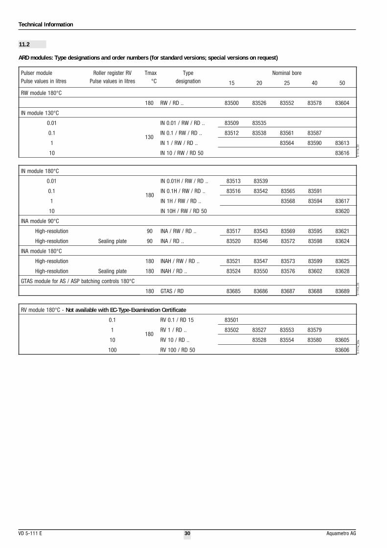
081eludomNI °C
10.0
081
..DR/WR/H10.0NI 31538 93538
1.0 ..DR/WR/H1.0NI 61538 24538 56538 19538
1 ..DR/WR/H1NI 86538 49538 71638
01 05DR/WR/H01NI 02638
09eludomANI °C
noituloser-hgiH 09 ..DR/WR/ANI 71538 34538 96538 59538 12638
noituloser-hgiH etalpgnilaeS 09 ..DR/ANI 02538 64538 27538 89538 42638
081eludomANI °C
noituloser-hgiH 081 ..DR/WR/HANI 12538 74538 37538 99538 52638
noituloser-hgiH etalpgnilaeS 081 ..DR/HANI 42538 05538 67538 20638 82638
081slortnocgnihctabPSA/SArofeludomSATG °C
081 DR/SATG 58638 68638 78638 88638 98638
5-11
1e_2
3
11.2
eludomresluP VRretsigerrelloR xamT epyT eroblanimoNsertilniseulavesluP sertilniseulavesluP °C noitangised 51 02 52 04 05
081eludomWR °C
081 ..DR/WR 00538 62538 25538 87538 40638
031eludomNI °C
10.0
031
..DR/WR/10.0NI 90538 53538
1.0 ..DR/WR/1.0NI 21538 83538 16538 78538
1 ..DR/WR/1NI 46538 09538 31638
01 05DR/WR/01NI 61638
5-11
1e_2
2
ARD modules: Type designations and order numbers (for standard versions; special versions on request)
081eludomVR ° -C etacifitreCnoitanimaxE-epyT-CEhtiwelbaliavatoN
1.0
081
51DR/1.0VR 10538
1 ..DR/1VR 20538 72538 35538 97538
01 ..DR/01VR 82538 45538 08538 50638
001 05DR/001VR 606385-
111e
_22a

Technical Information
Aquametro AG 31 VD 5-111 E
Type designation key (for device identification)
yeknoitangisedepytfoelpmaxE H1NI / 01VR / 52DR
resluP eulavesluPsertilni
xamT°C
enoN 081
evitcudnINI 10.0 031 10.0NI
1.0 1,0NI
1 1NI
01 01NI
10.0 081 H10.0NI
1.0 H1.0NI
1 H1NI
01 H01NI
noituloser-hgihevitcudnIANI 09 ANI
081 HANI
lortnocgnillifPSA/SArofeludoM SATG
retsigerrelloR WR
resluplargetnihtiwretsigerrelloR 1.0 1.0VR
1 1VR
01 01VR
001 001VR
retsigerrellortuohtiwetalpgnilaeS
retemwolffoeroblanimoN 51ND 51DR
02ND 02DR
52ND 52DR
04ND 04DR
05ND 05DR
stinuyalpsiD sertiL
snollagSU GSU
5-11
1e_2
4

Technical Information
VD 5-111 E 32 Aquametro AG
11.3
AMD measuring modules
Type designation key and order numbers (for standard versions)
Type designation key (for device identification)
gnisuoH /tinugnirusaeM NP xamT epyT eroblanimoNsgniraeb rab °C noitangised 52 04
0003DMA
leetssselniatS EFTP/leetssselniatS61
09 1333/..DMA 20048 60048
etihparg/leetssselniatS 081 2333/..DMA 30048 70048
yeknoitangisedepytfoelpmaxE DMA 52 / 3 3 3 1 / 051A
seiresepyT DMA DMA
eroblanimoN mm52 52
mm04 04
puorgnoitarugifnoC 0003/ 3
gnisuoH leetssselniatS 52NP 3
tinugnirusaeM leetssselniatS 3
sgniraeB EFTP 09 °C 1
etihparG 081 °C 2
sgnillirdegnalF NID 52/61NP
ISNA ISP051 051A
ISP003 003A
ISP006 006A
SIJ 01K 01J
61K 61J
03K 03J
5-11
1e_2
55-
111e
_26

Technical Information
Aquametro AG 33 VD 5-111 E
11.4
AMD modules
Type designation key and order numbers (for standard versions)
Type designation key (for device identification)
eludomresluP VRretsigerrelloR xamT epyT eroblanimoNsertilniseulavesluP sertilniseulavesluP °C noitangised 52 04
eludomWR
081 ..DM/WR 01048 61048
eludomVR
081 ..DM/1VR 04048 14048
eludomNI
1.0031
..DM/WR/1.0NI 21048 81048
1 ..DM/WR/1NI 31048 91048
1.0081
..DM/WR/H1.0NI tseuqerno
1 ..DM/WR/H1NI tseuqerno
eludomANI
noituloser-hgiH etalpgnilaeS 09 ..DM/ANI 51048 12048
081 ..DM/HANI tseuqerno
slortnocgnillifPSA/SArofeludomSATG
081 ..DM/SATG 41048 02048
5-11
1e_2
75-
111e
_28
yeknoitangisedepytfoelpmaxE 1NI / WR / 52DM
resluP eulavesluPsertilni
xamT°C
enoN
evitcudnINI 1.0031
1.0NI
1 1NI
noituloser-hgihevitcudnIANI 09 ANI
081 HANI
lortnocgnillifPSA/SArofeludoM SATG
retsigerrelloR 081 WR
reslupdetargetnihtiwretsigerrelloR 1 1VR
retemwolffoeroblanimoN 52ND 52DM
04ND 04DM
stinuyalpsiD sertiL

Technical Information
VD 5-111 E 34 Aquametro AG
rezilatotetomeR
/tuohtiw,petstnuoc=eulavesluptupnI)elbatsujda(gniorezhtiw
retnuocesluP3323YS 47339Am02...4/0retrevnoctnerrucycneuqerF
-cennocniseulavlangissuoenatnatsnirofsreslupANI/NInoituloser-hgihhtiwnoit
USF-MEW elbammargorpyleerF 00239
)snoitacilppaksirnoisolpxerof(XE/MEW elbammargorpyleerF 04239
AM
06
61
39
.4
5.65955.4
11.5
Complete PMD flowmeters: Order numbers
PMD: for versions without pulser or with reed-pulser type RH use type PMK (up to 40°C) or PMW (up to 90°C).
11.6
ATEX modifications
11.7
Data for ordering accessories
noitangisedepyT noisreV .oNredrO
1.0NI-02DMP l1.0NIresluphtiw )evitcudnI( 320481NI-02DMP l1NIresluphtiw )evitcudnI( 42048
ANI-02DMP reslupnoituloser-hgihhtiw )evitcudnI( tseuqernoretpada+02DMP metsyslortnocgnihctabrofderaperp 52048
1.0NI-52DMP l1.0NIresluphtiw )evitcudnI( 720481NI-52DMP l1NIresluphtiw )evitcudnI( 82048
ANI-52DMP reslupnoituloser-hgihhtiw )evitcudnI( tseuqernoretpada+52DMP metsyslortnocgnihctabrofderaperp 92048
1.0NI-04DMP l1.0NIresluphtiw )evitcudnI( 530481NI-04DMP l1NIresluphtiw )evitcudnI( 63048
ANI-04DMP reslupnoituloser-hgihhtiw )evitcudnI( tseuqernoretpada+04DMP metsyslortnocgnihctabrofderaperp 73048
AM066189.4
AM066015.4
AM
066078.4
5-11
1e_3
05-
111e
_31
secivedXETArofsnoitacifidoM 44069 5-11
1e_2
7a
snoitcennocdedaerhTslaesetiregnilKhtiw,mirtuohtiw,ssarB 51 02 52 04 05 .oNredrO
"2/1RSV • 06118
"2/1-"4/3RSV • 36118
"4/3RSV • 66118
"1RSV • 96118
"2/11RSV • 18118slortnocgnihctaB
slortnoclaunamSA tseuqerno
slortnoccitamuenpPSA tseuqerno

Technical Information
Aquametro AG 35 VD 5-111 E
DOMINO specification form
1. Customer and sales information
Name of customer ...........................................................................................................................................................................
Address ...........................................................................................................................................................................
Postal code, city, country ...........................................................................................................................................................................
Tel. No. ............................................................... Fax No. ....................................................................
Contact person ............................................................... Date ....................................................................
Object ............................................................... Measuring point ....................................................................
2. Operating conditions
Medium ............................................................... Formula ....................................................................
For impure or unfamiliar media, please give the follwoing data:
Pure, without solid or gas content Abrasive, fibrous, emulsion
If you already have experience with the medium, please indicate which of the following materials are chemically resistant to it:
• Metals Stainless steel Spherolitic cast iron Brass Aluminium anodized
• Plastics PTFE Hard-rubber Graphite
• Seals PTFE FPM ...................
Rated pressure PN ........................ Temperature range from .............................. to ............................ °C
Flow range from ....................... to ................................ l/h
Hazardous areas / non hazardous areas
3. Evaluation of measurements
Local totalizing with roller register
Pulse transmission to:
Analogue signal output to:
0...20 mA 4...20 mA
Filling batch size from ........................................................ to ................................ l in ................................................... Minutes
4. Installation conditions
Meter position Horizontal Vertical Other
Distance from evaluation unit Compact max. 5 m max. 50 m max. 500 m
5. Flowmeter specification Type DN Art. No. Price
• Metering module ................................... .......................................... ............................ ................................................
• Special flange ................................... ................................................
• Modules ................................... .......................................... ............................ ................................................
• Auxiliary modules ................................... .......................................... ............................ ................................................
Total ................................... ................................................
• Rated presure PN .............................. Temperature max. ......... °C
• Measuring range ................................... l/h ± ....................... %
• Neasuring range ................................... l/h ± ....................... %
• wetted components ......................................................................................................................................................................
......................................................................................................................................................................
6. Remarks ......................................................................................................................................................................
.............................................................................................................................................................................................................................................
.............................................................................................................................................................................................................................................
.............................................................................................................................................................................................................................................

Ände
rung
en v
orbe
halte
nSo
us ré
serv
e de
mod
ifica
tions
Mod
ifica
tion
right
s re
serv
edco
pyrig
ht ©
Aqu
amet
ro A
GA0
.5 -
07.
2003
-
Art .
Nr .
114
51
AQUAMETROMESSTECHNIK GmbHZum Panrepel 24
D-28307 Bremen
Tel. 0421 / 871 64-0
Fax 0421 / 871 64-19
AQUAMETRO AG
Ringstrasse 75
CH-4106 Therwil
Tel. 061 725 11 22
Fax 061 725 15 95
AQUAMETRO SA
Rue du Jura 2
CH-1800 Vevey
Tel. 021 / 923 51 30
Fax 021 / 922 58 44
AQUAMETRO s.r.o.
Prosecká 76
CZ-190 00 Praha 9
Tel. 02 / 86 88 77 78
Fax 02 / 86 88 95 59
AQUAMETROBELGIUM SPRLBd. Lambermont 131
B-1030 Bruxelles
Tel. 02 / 241 62 01
Fax 02 / 216 22 63
[email protected] www.aquametro.com


