31
OPERATION MANUAL ultracool mini 0010 – 0240 50/60Hz MI-063 rev.10 27.12.2004
| Date post: | 05-Mar-2015 |
| Category: |
Documents |
| Upload: | tasos-mythbuster |
| View: | 5,201 times |
| Download: | 174 times |
OPERATION MANUAL
ultracool mini 0010 – 0240 50/60Hz
MI-063 rev.1027.12.2004
- - 1
Warnings
Warnings
This Operation Manual is to be followed by all persons working with the unit. It is imperative that this Manual is made freely available at all times to service personnel and is kept at the point where the unit is installed. The basic maintenance, as indicated in point 6.1, should be carried out by properly trained personnel and, if necessary, under the supervision of a person qualified for this job. Ultrafilter personnel, or personnel authorised by ultrafilter, should carry out any work in the refrigerating or electric circuit during the warranty period. After the warranty period, the work must be carried out by qualified personnel.
MIN
I 50/
60H
z 19
.05.
03 R
ev. 5
- - 2
Table of Contents
Table of Contents 1 Introduction
1.1 General notes 31.2 Safety regulations 3
2 Possible installations
2.1 Superplus version 42.2 Standard version 4
3 Installation
3.1 Reception and inspection 53.2 Transportation 53.3 Site 53.4 Identification labels on the ultracool unit 63.5 Water connection 63.6 Electric connection 7
4 Start-up
4.1 Operating conditions 84.2 Before the start-up of the ultracool unit 84.3 Chiller start-up 9
5 Control Panel
5.1 Components of the control panel 115.2 Control thermostat 125.2.1 Operation 12
6 Maintenance
6.1 Basic maintenance 13 7 Troubleshooting
7.1 Possible causes of defaults 14 8 Technical Features
8.1 Technical Features 50Hz 168.2 Technical Features 60Hz 17
9 Log Book
9.1 Log Book 18 10 Annexes
10.1 Water Quality 19 11 Spare Parts
11.1 Spare parts 50Hz 2011.2 Spare parts 60Hz 21
12 Technical Diagrams
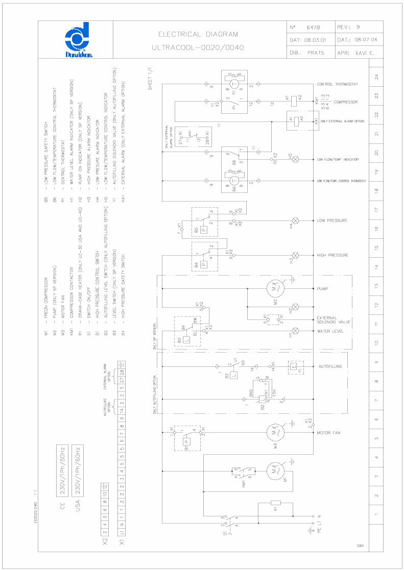
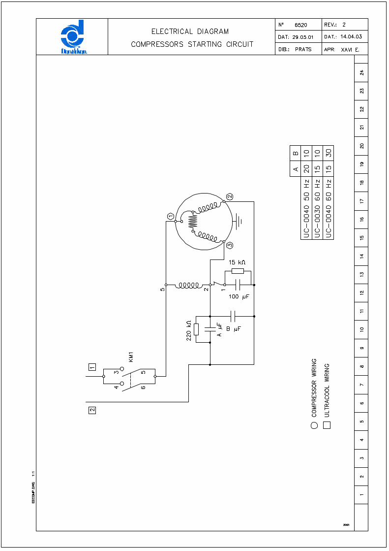
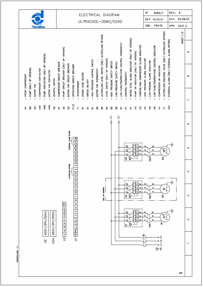
12.1 Dimensional sheet 2212.2 Flow sheet 12.3 Wiring sheet
13 Special Features
Attention. Points of special interest to keep in mind.
MIN
I 50/
60H
z 19
.05.
03 R
ev. 5

- - 3
1 Introduction
1 Introduction 1.1 General notes
• This water chiller complies fully with EC-machine directives and all its main components are UL and CSA listed.
• The Company does not accept responsibility if safety regulations are not met during handling, operation, maintenance and repair, even though these may not be strictly stated in this operation manual.
• We recommend the translation of this operation manual into the native language of foreign workers.
• The usability and life cycle of the water chiller as well as avoiding premature repairs depends on proper operation, maintenance, care and competent repair under consideration of this operation manual.
• We are constantly updating our products and are confident that they respond to the latest scientific and technological demands. However, as manufacturers, we do not always know the end use or the total range of our products’ applications. Therefore we cannot accept liability for our products in applications where additional safety measures may be necessary. We highly recommend that users inform us of the intended application in order to undertake additional safety measures, if necessary.
1.2 Safety regulations
The operator has to observe the national working, operating and safety regulations. Also, existing internal factory regulations must be met. Maintenance and repair work must only be carried out by specially trained personnel and, if necessary, under supervision of a person qualified for this work.
• Protective or safety devices must not be removed, modified or readjusted.
• During operation of the water chiller none of the protective or safety devices must be removed, modified or readjusted, temporarily or permanently.
• Only use correct tools for maintenance and repair work.
• Use original spare parts only.
• All maintenance and repair work must only be carried out to the machine once it has been stopped and disconnected from the power supply. Ensure that the water chiller cannot be switched on by mistake by unplugging it.
• Do not use flammable solvents for cleaning.
• Keep the surrounding area absolutely clean during maintenance and repair work. Keep free of dirt by covering the parts and free openings with clean cloth, paper or adhesive tape.
• Ensure that no tools, loose parts or similar are left inside the system.
MIN
I 50/
60H
z 19
.05.
03 R
ev. 5
- - 4
2 Possible Installations
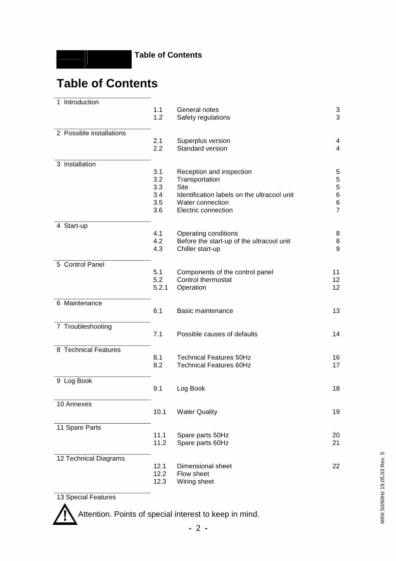
2 Possible Installations 2.1 Superplus Version
Without heat exchanger
2.2 Standard Version With an external water tank Several ultracool units with external tank When there are extensions foreseen (1) Permits to adjust the pressure drop of the user application according to the nominal pump pressure.
External by-pass Manual valve (1)
Filter
Use
Filter
Use
External by-pass
Manual valve(1)
Filter
Filter
Use 1Use 2
Manual valve(1)
Manual valve(1)
MIN
I 50/
60H
z 19
.05.
03 R
ev. 5
- - 5
3 Installation
3 Installation
3.1 Reception and Inspection
On receipt of the ultracool unit, it must be inspected for damage during transport. In the case of any damage, external or internal, this cannot be referred to the manufacturer because all units are checked before dispatch. If any damage is observed, this should be documented and reported to the forwarding company. The ultrafilter warranty does not include any damages incurred during transportation.
The refrigerant circuit controls are set before shipment of the unit. They should not be re-adjusted under any circumstances (except by our ultrafilter service department). This would void the warranty of the unit.
3.2 Transportation
Keep the unit upright at all times. Do not tilt when shipping or moving. The tilting of the ultracool unit may affect the internal suspension of the refrigerant compressor.
The ultracool unit must be transported by palet jack or forklift truck.
3.3 Site
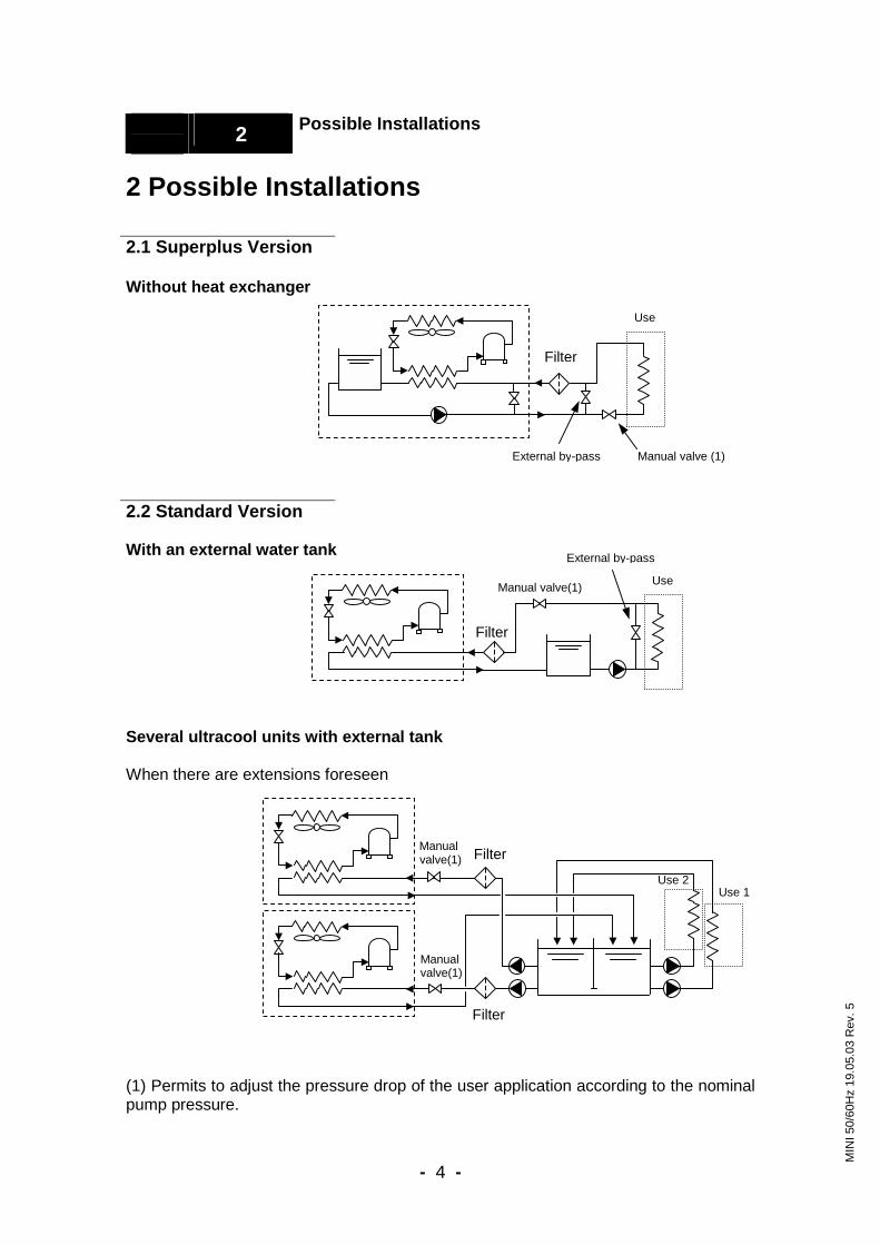
We recommend the installation of the ultracool unit in a well-ventilated site and in a corrosive-free, dust-free atmosphere. The air renewal of the room should be at least ¾ of chiller’s motor fan flow (see point 8.1). The electrical protection degree of the ultracool unit is IP54 (except models UC-10 to UC-40, which have an IP44 protection degree). In the case of out-door installation (only from UC-60 up to UC-240) the chiller must be protected from rain with a roof and it must be installed in such way that the control panel receives as few direct sunlight as possible. The inlet of fresh air onto the condenser should be in the most direct way possible, avoiding any chance of air recycling .
See in the picture the minimum distances (m) around the ultracool unit:
1 1
1
1
H+1
H: chiller’s height (See point 12.1)
MIN
I 50/
60H
z 19
.05.
03 R
ev. 5

- - 6
3 Installation
3.4 Identification Labels on the ultracool unit
You can find the following labels stuck on the ultracool unit.
3.5 Water Connection
Superplus models: It is mandatory to install a manual valve to adjust the pressure drop in the user system in accordance with the nominal pump pressure (See point 8.1). Standard models: The user pump must provide the chiller with the flow indicated in the ultracool characteristics plate (See point 8.1). Take into account that the maximum pressure at the chiller’s inlet cannot exceed 6 bar. It is necessary to install a water filter at the inlet of the chiller in order to avoid free particles in the water, which could block the evaporator plates or damage the pump. ultrafilter will not accept any warranty for the evaporator damage or performance loss if there is no water filter. An appropriate filter is the ultrafilter P-KG with a PPTF or similar with a filter element of 100 microns or less.
Water inlet from the installation to the ultracool unit.
Water outlet from the ultracool unit to the installation.
Connection to fill the tank. (except UC 10, 20, 30 and 40).
Drain. Connection for the tank overflow. (except UC 10, 20, 30 and 40).
Arrow showing turn direction of pump.
Danger of cuts! Completely disconnect the chiller’s power supply before opening this cover.
Power suply depending on version
---V/-Ph/--Hz
MIN
I 50/
60H
z 19
.05.
03 R
ev. 5
- - 7
3 Installation
The water connection of the installation of the ultracool unit should be carried out according to the indications of the labels (stickers) present on the unit. In the UC-10 to UC-40 units the tank has to be filled directly by removing the chiller and tank covers. The diameter of the inlet and outlet lines must be same size or larger than those corresponding to the water inlet and outlet of the ultracool unit. Always install thermal insulation for all pipes. In the installations in which the water level of the circuit exceeds the maximum level of the tank inside the ultracool unit, it will be necessary to install a non-return valve in the water outlet of the ultracool unit and a solenoid valve in the water inlet. Terminals at 230 VAC are designed for that purpose, except for the UC-10, to carry out the supply of this solenoid valve. (see electrical diagrams).
3.6 Electrical Connection
The electrical design of the ultracool complies with EN-60204 norms. It must be checked that the supply voltage does not exceed a maximum variation of 10% referring to nominal. For the electrical supply of the ultracool unit, use an appropriate electrical line according to the data in the characteristics plate. (See also point 8.1) A system of fuses or circuit breakers must be installed before the power inlet connection to the ultracool unit. The maximum size of these protections is defined in the ultracool characteristics plate. In the three phases models there are two prepared terminals to connect a remote on-off switch away from the unit. These terminals are at 230V.
MIN
I 50/
60H
z 19
.05.
03 R
ev. 5
- - 8
4 Start-up
4 Start-up 4.1 Operation Conditions
Water temperature at the inlet:
Nominal: 15ºC (60ºF) Maximum: 30ºC (86ºF)
Cold water temperature at the outlet:
Nominal: 10ºC (50ºF) Minimum: 7ºC (45ºF) (2) Maximum: 25ºC (77ºF)
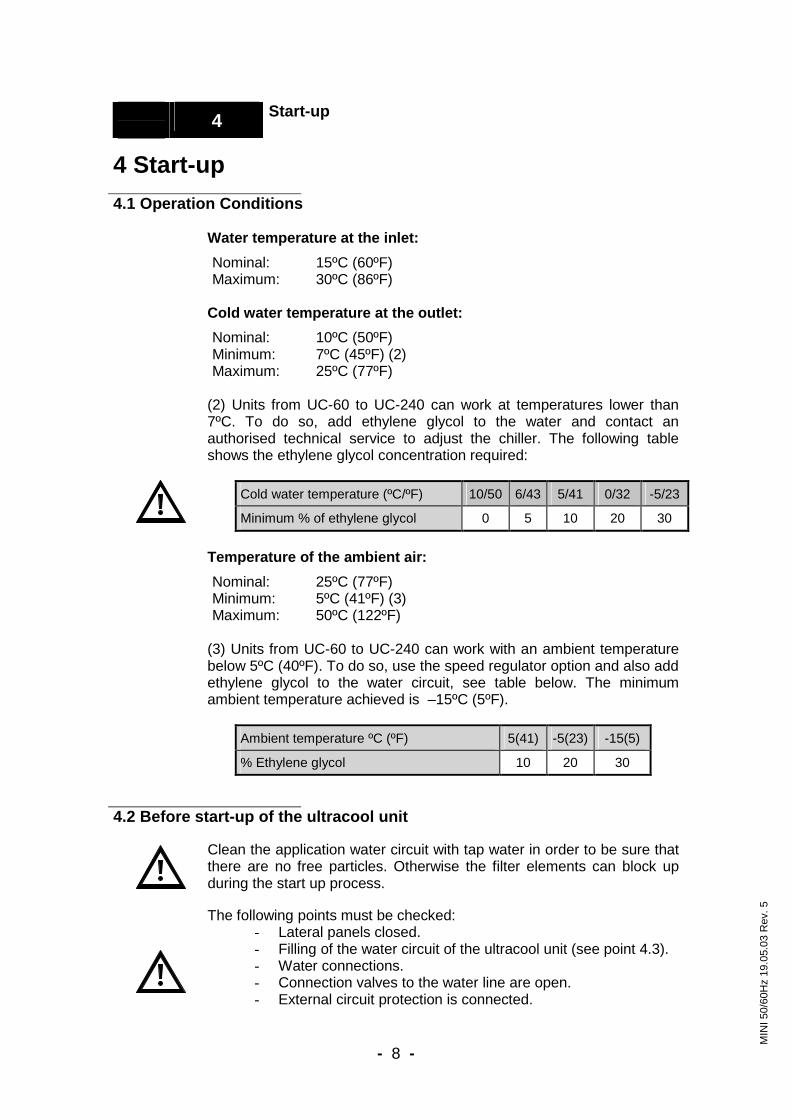
(2) Units from UC-60 to UC-240 can work at temperatures lower than 7ºC. To do so, add ethylene glycol to the water and contact an authorised technical service to adjust the chiller. The following table shows the ethylene glycol concentration required:
Cold water temperature (ºC/ºF) 10/50 6/43 5/41 0/32 -5/23
Minimum % of ethylene glycol 0 5 10 20 30
Temperature of the ambient air:
Nominal: 25ºC (77ºF) Minimum: 5ºC (41ºF) (3) Maximum: 50ºC (122ºF)
(3) Units from UC-60 to UC-240 can work with an ambient temperature below 5ºC (40ºF). To do so, use the speed regulator option and also add ethylene glycol to the water circuit, see table below. The minimum ambient temperature achieved is –15ºC (5ºF).
Ambient temperature ºC (ºF) 5(41) -5(23) -15(5)
% Ethylene glycol 10 20 30 4.2 Before start-up of the ultracool unit
Clean the application water circuit with tap water in order to be sure that there are no free particles. Otherwise the filter elements can block up during the start up process. The following points must be checked:
- Lateral panels closed. - Filling of the water circuit of the ultracool unit (see point 4.3). - Water connections. - Connection valves to the water line are open. - External circuit protection is connected.
MIN
I 50/
60H
z 19
.05.
03 R
ev. 5

- - 9
4 Start-Up
4.3 Chiller start-up
When the ultracool unit is started for the first time, it is necessary to turn ON the Main power switch (element 1 in the control panel, see point 5) and wait six hours before continuing with the start-up sequence. This time is necessary for the crankcase of the compressor to heat it up in the models that have it (UC-60 to UC-240). The oil in the crankcase of the compressor remains warm whenever the main power switch is in the ON position and the unit is connected to the line voltage. For this reason stop the ultracool unit by using the off-switch, leaving the Main power switch in the ON position. Fill the tank with water of the required quality (see annex 10) or with refrifluid through the provided connection until the maximum level of the tank is reached. Start the ultracool unit with the On/Off switch (element 2 in the control panel, see point 5). Stop the ultracool unit and refill the tank to the correct water level. Repeat this procedure until the water level in the tank remains constant. In the three phase units, from UC-60 to UC-240, of the superplus version it is necessary to verify the direction of rotation of the pump at the initial start up. To do so, start and stop the ultracool unit, using the On/Off switch (it is easier to see the turn direction when the pump is stopping). In the case of the pump rotating in the opposite direction from the indicated, it will be necessary to exchange two phases in the main power supply. It will not be necessary to check the turn direction of the fans, because they are delivered in phase with the pump. Since it may be difficult to see the pump’s rotation direction, verify that you did this operation correctly when the motor fan starts working: The air should enter the condenser and go out through the top of the chiller. If the air is moving in the opposite direction then exchange two phases in the main power supply. In the standard models, it will be necessary to check the direction of rotation of the fans, to do so, follow the procedure described in the last paragraph. Connect the On/Off switch so that the ultracool unit starts. At the same time the digital thermometer and all the indicators that should light up will turn on too, according to their function. Adjust the water pressure, using the external valve at the ultracool outlet, to the value indicated on the carachteristics plate (Nominal pressure).
MIN
I 50/
60H
z 19
.05.
03 R
ev. 5
- - 10
5 Control Panel
5 Control Panel
Models UC-20 to UC-40:
Models UC-60 to UC-240:
Model UC-10:
Pressure gauges:
MIN
I 50/
60H
z 19
.03.
04 R
ev. 8
12 13
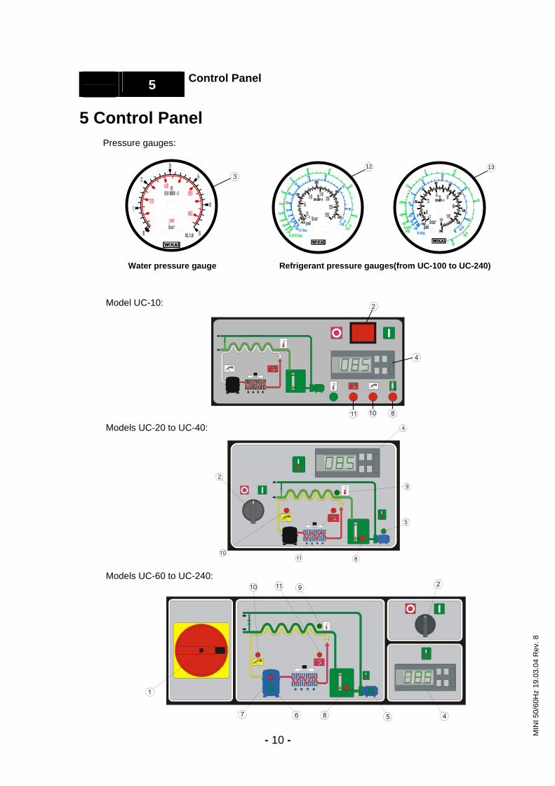
Water pressure gauge Refrigerant pressure gauges(from UC-100 to UC-240)
- - 11
5 Control Panel
5.1 Components of the Control Panel
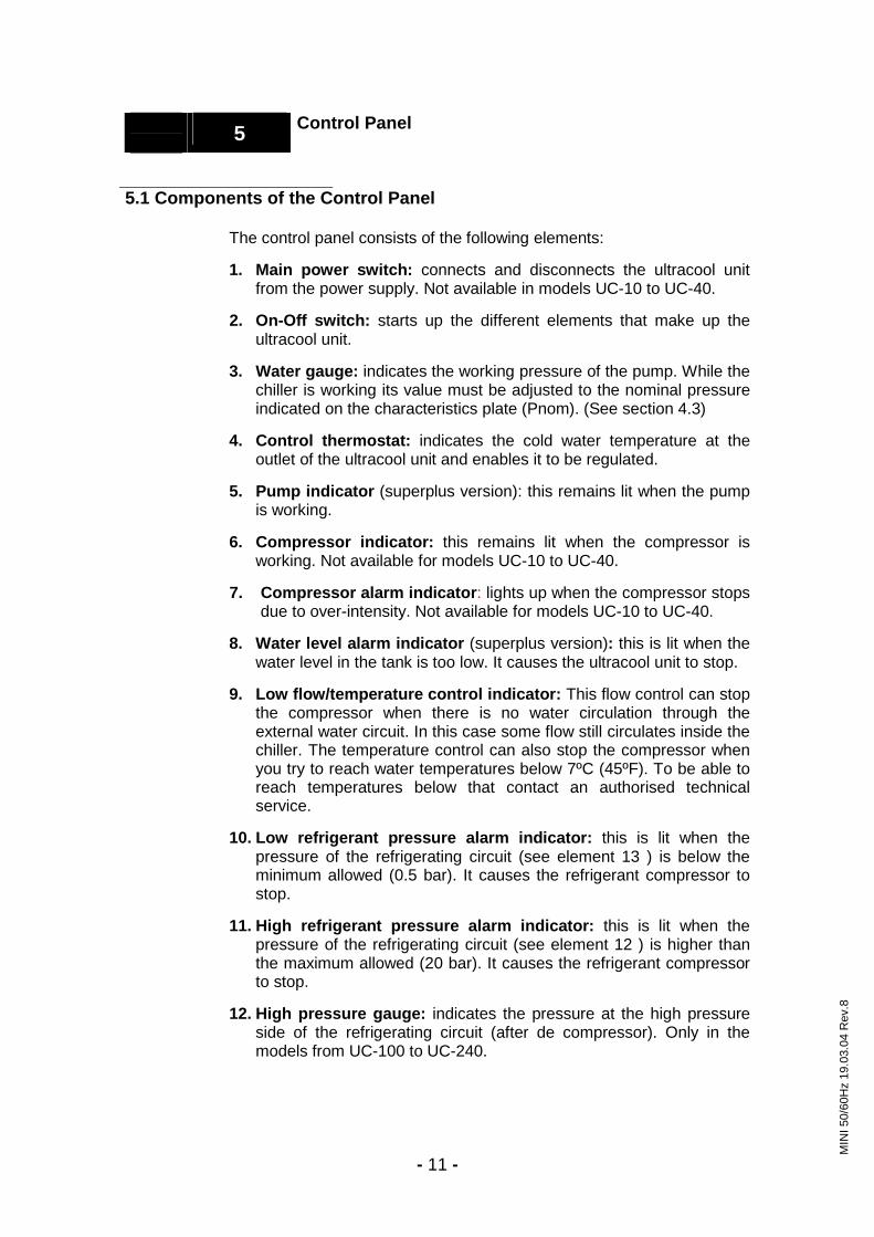
The control panel consists of the following elements: 1. Main power switch: connects and disconnects the ultracool unit
from the power supply. Not available in models UC-10 to UC-40.
2. On-Off switch: starts up the different elements that make up the ultracool unit.
3. Water gauge: indicates the working pressure of the pump. While the
chiller is working its value must be adjusted to the nominal pressure indicated on the characteristics plate (Pnom). (See section 4.3)
4. Control thermostat: indicates the cold water temperature at the
outlet of the ultracool unit and enables it to be regulated.
5. Pump indicator (superplus version): this remains lit when the pump is working.
6. Compressor indicator: this remains lit when the compressor is
working. Not available for models UC-10 to UC-40.
7. Compressor alarm indicator: lights up when the compressor stops due to over-intensity. Not available for models UC-10 to UC-40.
8. Water level alarm indicator (superplus version): this is lit when the
water level in the tank is too low. It causes the ultracool unit to stop.
9. Low flow/temperature control indicator: This flow control can stop the compressor when there is no water circulation through the external water circuit. In this case some flow still circulates inside the chiller. The temperature control can also stop the compressor when you try to reach water temperatures below 7ºC (45ºF). To be able to reach temperatures below that contact an authorised technical service.
10. Low refrigerant pressure alarm indicator: this is lit when the
pressure of the refrigerating circuit (see element 13 ) is below the minimum allowed (0.5 bar). It causes the refrigerant compressor to stop.
11. High refrigerant pressure alarm indicator: this is lit when the
pressure of the refrigerating circuit (see element 12 ) is higher than the maximum allowed (20 bar). It causes the refrigerant compressor to stop.
12. High pressure gauge: indicates the pressure at the high pressure
side of the refrigerating circuit (after de compressor). Only in the models from UC-100 to UC-240.
MIN
I 50/
60H
z 19
.03.
04 R
ev.8

- - 12
5 Control Panel
13. Low pressure gauge: indicates the pressure at the low pressure side of the refrigerating circuit (before the compressor). Only in the models from UC-100 to UC-240.
5.2 Control Thermostat
5.2.1 Operation
During normal operating conditions, the display of the control thermostat shows the cold water outlet temperature measured by the probe.
In the case of alarm, the display flashes the activated alarm code alternately with the probe temperature.
Setting the temperature: to introduce the required working temperature (between –5 and 25) the following procedure should be followed:
- Hold down for 2 seconds the button set and the current set temperature will start flashing.
- To increase or to decrease the value of the setpoint, use the UP and DOWN buttons.
- Press set again to confirm the new value.
set
MIN
I 50/
60H
z 19
.03.
04 R
ev. 6

- - 13
6 Maintenance
6 Maintenance 6.1 Basic Maintenance
Weekly: Verify that the water temperature indicated on the control thermostat is approximately at the setpoint. Verify that the pressure of the pump is the same as the nominal pressure (Pnom) indicated in the characteristics plate. Verify the water level in the tank. Verify the state of the water filter, if the pressure drop exceeds 0.5 bar (8 psi) change the filter element. Monthly: With the unit disconnected (Main power switch Off), clean the condenser with a blast of compressed air, from the inside towards the outside. Clean the housing, internally and externally, eliminating the dust present especially on the water pump rack. Yearly: Change the filter element and refill the water circuit with clean water or refrifluid.
MIN
I 50/
60H
z 19
.05.
03 R
ev. 5
- - 14
7 Troubleshooting
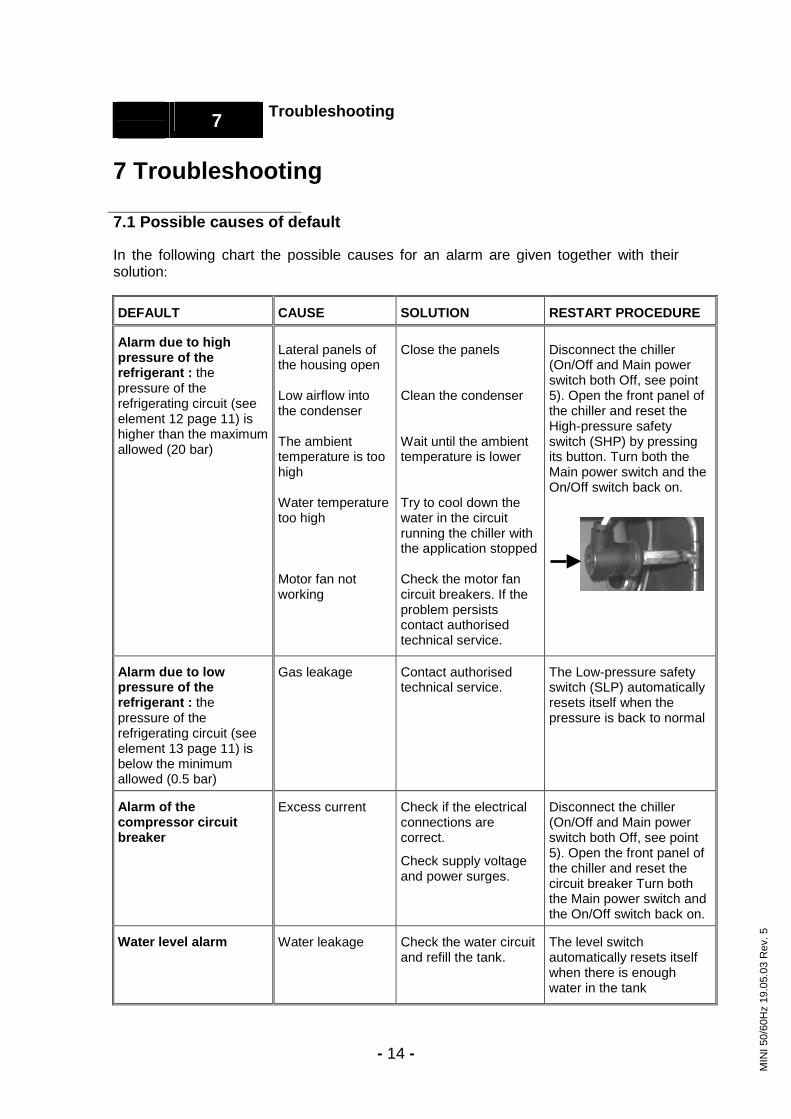
7 Troubleshooting 7.1 Possible causes of default In the following chart the possible causes for an alarm are given together with their solution:
DEFAULT CAUSE SOLUTION RESTART PROCEDURE
Alarm due to high pressure of the refrigerant : the pressure of the refrigerating circuit (see element 12 page 11) is higher than the maximum allowed (20 bar)
Lateral panels of the housing open Low airflow into the condenser The ambient temperature is too high Water temperature too high Motor fan not working
Close the panels Clean the condenser Wait until the ambient temperature is lower Try to cool down the water in the circuit running the chiller with the application stopped Check the motor fan circuit breakers. If the problem persists contact authorised technical service.
Disconnect the chiller (On/Off and Main power switch both Off, see point 5). Open the front panel of the chiller and reset the High-pressure safety switch (SHP) by pressing its button. Turn both the Main power switch and the On/Off switch back on.
Alarm due to low pressure of the refrigerant : the pressure of the refrigerating circuit (see element 13 page 11) is below the minimum allowed (0.5 bar)
Gas leakage Contact authorised technical service.
The Low-pressure safety switch (SLP) automatically resets itself when the pressure is back to normal
Alarm of the compressor circuit breaker
Excess current Check if the electrical connections are correct.
Check supply voltage and power surges.
Disconnect the chiller (On/Off and Main power switch both Off, see point 5). Open the front panel of the chiller and reset the circuit breaker Turn both the Main power switch and the On/Off switch back on.
Water level alarm Water leakage Check the water circuit and refill the tank.
The level switch automatically resets itself when there is enough water in the tank
MIN
I 50/
60H
z 19
.05.
03 R
ev. 5

- - 15
7 Troubleshooting
DEFAULT CAUSE SOLUTION RESTART PROCEDURE
Low flow/temperature control operates continuously (see point 5) (only from UC-20 to UC-240).
Cold water temperature is required to be below 7ºC Water circuit blocked Possible freezing Circuit break in the pump
Add ethylene glycol to the water and change the low flow/temperature control setpoint Clean the water circuit, check for closed valves in the circuit. Check the proportion of ethylene glycol. Reset the circuit breaker of the pump. If the problem persists contact authorised technical service
The control will go back to normal operation when the problem is solved
The control thermostat displays the following codes: LO HI E0, Er2, EE
The temperature has been below the setpoint for some minutes The temperature has been above the setpoint for some minutes Thermostat or temperature sensor is faulty
If the compressor is stopped the water temperature will rise to normal eventually. If the compressor is still running contact authorised technical service Check that the cold water setpoint is within the limits indicated on point 4.1. If the problem persists contact authorised technical service Contact authorised technical service
The chiller is still working normally The chiller is still working normally The chiller can be restarted when the faulty part is replaced
MIN
I 50/
60H
z 19
.05.
03 R
ev. 5

- - 16
8 Technical Features
8 Technical Features
8.1 Technical Features 50Hz
UC 10 20 30 40 60 80 100 140 180 240 kcal/h 602 1686 3087 4137 6020 7989 10079 13141 18765 25215Cooling capacity
kW 0,70 1,96 3,59 4,81 7,00 9,29 11,72 15,28 21,82 29,32Water flow l/h 120 337 617 827 1204 1598 2016 2628 3753 5043
3 bar 3,6 3,5 3,5 3,4 3,3 3,0 2,8 2,8 3,5 2,8Water pressure 5 bar 0,6* 5,4 5,2 5,1 5,5 5,4 5,3 5,1 5,5 5,3
Refrigerant charge kg R134a 0,8 1,4 1,5 2,0 4,0 4,5 7,0 7,0 12,0 12,0Refrigerant circuits Nº 1 1 1 1 1 1 1 1 1 1
kW 0,43 0,80 1,05 1,25 1,85 2,45 3,05 4,00 5,30 7,30Compressor Nº 1 1 1 1 1 1 1 1 1 1kW 1,79 3,41 5,67 8,73 12,62 12,98 19,53 23,95 37,75 42,77Condenser Nº 1 1 1 1 1 1 1 1 1 1kW 1,27 3,14 4,97 4,97 9,94 11,35 15,47 19,41 25,97 37,24Evaporator Nº 1 1 1 1 1 1 1 1 1 1Nº 1 1 1 1 1 1 1 1 1 1kW 0,02 0,12 0,13 0,13 0,42 0,42 0,66 0,66 0,98 0,98Motor fan
m3/h 500 1500 2200 2200 6000 6000 8800 8300 13000 12600 kW 0,57 0,57 0,57 0,57 0,62 0,62 0,62 0,69 0,75 0,75
max 3500 3500 3500 3500 3500 3500 3500 3500 8000 8000min
l/h 100 100 100 100 350 350 350 350 800 800
max 3,6 3,6 3,6 3,6 3,5 3,5 3,5 4,2 4,5 4,53 bar pump
min bar
1,6 1,6 1,6 1,6 1,8 1,8 1,8 2 1 1 kW 0,12* 0,90 0,90 0,90 1,10 1,10 1,10 1,10 1,85 1,85
max 5000* 3400 3400 3400 8000 8000 8000 8000 12000 12000min
l/h 100* 340 340 340 800 800 800 800 1200 1200
max 0,7* 5,5 5,5 5,5 5,6 5,6 5,6 5,6 6 65 bar pump
min bar
0,1* 2,5 2,5 2,5 1,8 1,8 1,8 1,8 3 3Volume water tank l 6 35 35 35 75 75 100 100 200 200Water connections 3/8" 1/2" 1/2" 1/2" 3/4" 3/4" 1" 1" 1" 1"
Front mm 520 530 584 584 800 800 845 845 950 950Depth mm 415 630 713 713 880 880 990 990 1140 1140Dimensions Height mm 692 890 1120 1120 1135 1135 1235 1235 1635 1635
ST kg - 100 105 110 165 180 215 235 345 365Weight SP kg 60 115 120 125 185 200 235 260 375 400ST kW - 0,92 1,18 1,38 2,27 2,87 3,71 4,66 6,28 8,28
SP 3bar kW 1,02 1,49 1,75 1,95 2,89 3,49 4,33 5,35 7,03 9,03Power SP 5bar kW 0,57* 1,82 2,08 2,28 3,37 3,97 4,81 5,76 8,13 10,13
Max. fuse A 16,0 16,0 16,0 16,0 20,0 25,0 25,0 25,0 32,0 40,0Voltage V/P/Hz 230V/1/50 Hz 400V/3+N/50 Hz Nominal COP 1,56 2,13 3,04 3,49 3,08 3,24 3,16 3,28 3,47 3,54 * The UC-10 SP does not have the option of a 5 bar pump. This data corresponds to the option with a 0,6 bar recirculating pump. All data related to nominal conditions: Water outlet temperature 10ºC and ambient temperature 25ºC.
MIN
I 50/
60H
z 27
.12.
04 R
ev. 8

- - 17
8 Technical Features
8.2 Technical Features 60Hz
UC 10 20 30 40 60 80 100 140 180 240 ton 0,18 0,35 0,77 1,03 1,97 2,39 3,20 4,02 5,54 7,69Cooling capacity kW 0,65 1,24 2,70 3,62 6,93 8,43 11,26 14,16 19,50 27,06
Water flow US gal/min 0,44 0,85 1,84 2,47 4,73 5,75 7,68 9,66 13,30 18,4640 psi 48 48 46 46 51 49 45 42 44 41Water pressure 70 psi 9* 75 74 73 70 68 78 70 67 68
Refrigerant charge lb R134a 1,8 3,1 3,3 4,4 8,8 9,9 15,4 15,4 26,4 26,4Refrigerant circuits Nº 1 1 1 1 1 1 1 1 1 1
kW 0,48 0,83 1,07 1,36 2,73 3,19 4,13 5,28 6,80 9,70Compressor Nº 1 1 1 1 1 1 1 1 1 1ton 0,51 0,97 1,61 2,48 3,58 3,69 5,55 6,80 10,72 12,15Condenser Nº 1 1 1 1 1 1 1 1 1 1ton 0,36 0,89 1,41 1,41 2,82 3,22 3,73 4,68 6,27 8,99Evaporator Nº 1 1 1 1 1 1 1 1 1 1Nº 1 1 1 1 1 1 1 1 1 1kW 0,02 0,16 0,19 0,19 0,66 0,66 1,05 1,05 1,55 1,55Motor fan
scfm 324 1001 1471 1471 3944 3944 6004 5592 8829 8593 kW 0,7 0,7 0,7 0,7 0,78 0,78 0,78 0,78 0,94 1,27
max 18,5 18,5 18,5 18,5 17,6 17,6 17,6 17,6 17,6 35,2min
US gal/min 0,4 0,4 0,4 0,4 1,8 1,8 1,8 1,8 1,8 3,5
max 51 51 51 51 52 52 52 52 73 5240 psi pump
min psi
15 15 15 15 26 26 26 26 38 22 kW 0,12* 1,00 1,00 1,00 0,94 0,94 1,00 1,00 1,30 2,10
max 18,5* 18,5 18,5 18,5 17,6 17,6 17,6 17,6 17,6 52,8min
US gal/min 0,4* 0,4 0,4 0,4 1,8 1,8 1,8 1,8 1,8 5,3
max 10* 78 78 78 73 73 91 91 117 7770 psi pump
min psi
1* 22 22 22 38 38 48 48 59 33Volume water tank US gal 1,6 9,2 9,2 9,2 19,8 19,8 26,4 26,4 52,8 52,8Water connections (NPT) 3/8" 1/2" 1/2" 1/2" 3/4" 3/4" 1" 1" 1" 1"
Front in 20 21 23 23 31 31 33 33 37 37Depth in 16 25 28 28 35 35 39 39 45 45Dimensions Height in 27 35 44 44 45 45 49 49 64 64
ST lb - 220 231 243 364 397 474 518 761 805Weight SP lb 132 254 265 276 408 441 518 573 827 882ST kW - 0,99 1,26 1,55 3,39 3,85 5,18 6,33 8,35 11,25
SP 40psi kW 1,20 1,69 1,96 2,25 4,17 4,63 5,96 7,11 9,29 12,52Power SP 70psi kW 0,62* 1,99 2,26 2,55 4,33 4,79 6,18 7,33 9,65 13,35
Max. Fuse A 16 16 16 16 20 25 25 25 32 40Voltage V/P/Hz 230/1/60 Hz 460/3/60 Hz Nominal COP 1,30 1,25 2,14 2,34 2,04 2,19 2,17 2,24 2,34 2,41 *The UC-10 SP does not have the option of a 70 psi pump. This data corresponds to the option with a 9 psi recirculating pump. All data related to the following conditions: Water outlet temperature 10ºC (50ºF) and ambient temperature 25ºC (77ºF).
MIN
I 50/
60H
z 27
.12.
.04
Rev
. 8

- - 18
9 Log Book
9 Log Book 9.1 Log Book
Date Remarks Signature
MIN
I 50/
60H
z 19
.05.
03 R
ev. 5
- - 19
10 Annexes
10 Annexes 10.1 Water quality
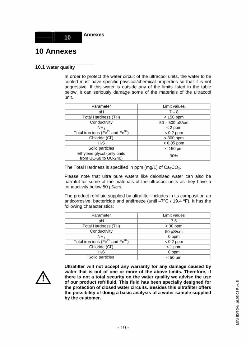
In order to protect the water circuit of the ultracool units, the water to be cooled must have specific physical/chemical properties so that it is not aggressive. If this water is outside any of the limits listed in the table below, it can seriously damage some of the materials of the ultracool unit.
Parameter Limit values pH 7 – 8
Total Hardness (TH) < 150 ppm Conductivity 50 – 500 µS/cm
NH3 < 2 ppm Total iron ions (Fe2+ and Fe3+) < 0.2 ppm
Chloride (Cl-) < 300 ppm H2S < 0.05 ppm
Solid particles < 150 µm Ethylene glycol (only units
from UC-60 to UC-240) 30%
The Total Hardness is specified in ppm (mg/L) of Ca2CO3. Please note that ultra pure waters like deionised water can also be harmful for some of the materials of the ultracool units as they have a conductivity below 50 µS/cm. The product refrifluid supplied by ultrafilter includes in its composition an anticorrosive, bactericide and antifreeze (until –7ºC / 19.4 ºF). It has the following characteristics:
Parameter Limit values pH 7.5
Total Hardness (TH) < 30 ppm Conductivity 50 µS/cm
NH3 0 ppm Total iron ions (Fe2+ and Fe3+) < 0.2 ppm
Chloride (Cl-) < 1 ppm H2S 0 ppm
Solid particles < 50 µm Ultrafilter will not accept any warranty for any damage caused by water that is out of one or more of the above limits. Therefore, if there is not a total security on the water quality we advise the use of our product refrifluid. This fluid has been specially designed for the protection of closed water circuits. Besides this ultrafilter offers the possibility of doing a basic analysis of a water sample supplied by the customer.
MIN
I 50/
60H
z 19
.05.
03 R
ev. 5

-
- 20
11
Sp
are
part
s
11.1
Spa
re p
arts
50H
z
UC
-10
UC
-20
UC
-30
UC
-40
UC
-60
UC
-80
UC
-100
U
C-1
40
UC
-180
U
C-2
40
Com
pres
sor
0111
3640
00
0106
2630
0001
0641
6000
01
0636
2000
01
0649
7000
01
0635
9000
01
0065
0000
01
0016
5000
01
1122
9000
01
1123
0000
C
onde
nser
E
5211
114
L700
0060
00L7
0000
7000
L7
0000
8000
E
3751
050
E37
5105
0 E
3751
052
E37
5105
4 E
3751
023
E37
5106
0 Ev
apor
ator
E
5291
002
E52
9300
7 E
5293
010
E52
9301
0 E
5293
014
E52
9301
4 E
5293
018
E52
9301
8 E
5293
020
E52
9303
2 M
otor
fan
E52
0140
6 01
0301
9000
0108
0530
00
0108
0530
00
E52
0425
0 E
5204
250
E52
0425
2 E
5204
252
E52
0426
0 E
5204
260
Pum
p 3b
ar
E45
2163
2 E
4521
632
E45
2163
2 E
4521
632
E45
2139
0 E
4521
390
E45
2139
0 E
4521
391
E45
2139
2 E
4521
392
Pum
p 5b
ar
E45
2171
0 E
4521
389
E45
2138
9 E
4521
389
E45
2139
4 E
4521
394
E45
2137
4 E
4521
374
E45
2139
7 E
4521
397
Wat
er ta
nk
E35
8100
2 E
3590
002
E35
9000
2 E
3590
002
E35
9000
4 E
3590
004
E35
4002
6 E
3540
026
E35
4001
4 E
3540
014
Liqu
id v
esse
l ---
---
---
---
E
5351
012
E53
5101
2 C
21 0
129
000
C21
012
9 00
0C
21 0
130
000
C21
013
0 00
0 Ex
pans
ion
valv
e E
5334
502
0110
6490
0001
1064
9000
01
1064
9000
01
1065
0000
01
1065
0000
01
0180
7000
01
0180
7000
01
0185
2000
01
0201
5000
D
ryer
filte
r 01
1209
3000
01
1209
3000
0112
0930
00
0112
0930
00
0112
0630
00
0112
0630
00
0112
0950
00
0112
0950
00
0112
0950
00
0112
0950
00
Hig
h pr
essu
re c
ontr
ol s
witc
h ---
01
0308
7000
0103
0870
00
0103
0870
00
0103
0870
00
0103
0870
00
0103
0870
00
0103
0870
00
0103
0870
00
0103
0870
00
Hig
h pr
essu
re s
afet
y sw
itch
0106
4370
00
0106
4370
0001
0643
7000
01
0643
7000
01
0643
7000
01
0643
7000
01
0643
7000
01
0643
7000
01
0643
7000
01
0643
7000
Lo
w p
ress
ure
safe
ty s
witc
h 01
1014
0000
01
1014
0000
0110
1400
00
0110
1400
00
0110
1400
00
0110
1400
00
0110
1400
00
0110
1400
00
0110
1400
00
0110
1400
00
Con
trol
ther
mos
tat
E53
2604
2 E
5326
042
E53
2604
2 E
5326
042
E53
2604
2 E
5326
042
E53
2604
2 E
5326
042
E53
2604
2 E
5326
042
Low
flow
/tem
pera
ture
con
trol
th
erm
osta
t E
5326
042
E53
2604
2 E
5326
042
E53
2604
2 E
5326
042
E53
2604
2 E
5326
042
E53
2604
2 E
5326
042
E53
2604
2
Sigh
t gla
ss
---
---
---
---
---
---
0107
3970
00
0107
3970
00
0107
3970
00
0107
3970
00
Ref
riger
ant g
as
R-1
34a
( 0,8
kg )
R-1
34a
(1,4
kg)
R
-134
a
(1,5
kg)
R
-134
a (2
,0 k
g)
R-1
34a
(6
,0 k
g)
R-1
34a
(6
,5 k
g)
R-1
34a
(1
1,0
kg)
R-1
34a
(14,
0 kg
) R
-134
a (1
9,0
kg)
R-1
34a
(1
9,0
kg)
Leve
l con
trol
E
4203
002
E42
0200
4 E
4202
004
E42
0200
4 E
4202
004
E42
0200
4 E
4202
004
E42
0200
4 E
4202
004
E42
0200
4 W
ater
by-
pass
E
2301
002
E23
0100
2 E
2301
002
E23
0100
2 E
2301
002
E23
0100
2 E
2301
002
E23
0100
2 E
2301
002
E23
0100
2 Pu
mp
pres
sure
gau
ge 3
bar
E55
4401
2 E
5544
012
E55
4401
2 E
5544
012
E55
4401
2 E
5544
012
E55
4401
2 E
5544
012
E55
4401
2 E
5544
012
Pum
p pr
essu
re g
auge
5ba
r E
5544
020
E55
4401
4 E
5544
014
E55
4401
4 E
5544
014
E55
4401
4 E
5544
014
E55
4401
4 E
5544
014
E55
4401
4 C
ompr
esso
r con
tact
or
E42
5151
2 E
4251
512
E42
5140
1 E
4251
401
E42
4200
4 E
4242
006
E42
4202
0 E
4242
022
E42
4202
2 E
4242
024
Pum
p co
ntac
tor 3
bar
---
---
---
---
E42
5140
2 E
4251
402
E42
5140
2 E
4251
402
E42
5140
2 E
4251
402
Pum
p co
ntac
tor 5
bar
---
---
---
---
E42
5140
2 E
4251
402
E42
5140
2 E
4251
402
E42
4200
2 E
4242
002
Mot
or fa
n co
ntac
tor
---
---
---
---
E42
5140
2 E
4251
402
E42
4200
2 E
4242
002
E42
4200
2 E
4242
002
Com
pres
sor's
circ
uit b
reak
er
---
---
---
---
E42
6604
6 E
4266
046
E42
6610
4 E
4266
104
E42
6610
4 E
4266
126
Pum
p's
circ
uit b
reak
er 3
bar
---
---
---
---
E42
6602
6 E
4266
026
E42
6602
6 E
4266
026
E42
6603
0 E
4266
030
Pum
p's
circ
uit b
reak
er 5
bar
---
---
---
---
E42
6603
2 E
4266
032
E42
6603
4 E
4266
034
E42
6603
8 E
4266
038
Mot
or fa
n's
circ
uit b
reak
er
---
---
---
---
E42
6602
4 E
4266
026
E42
6602
8 E
4266
028
E42
6603
0 E
4266
030
Gen
eral
sw
itch
---
---
---
---
E42
9200
6 E
4292
007
E42
9200
7 E
4292
012
E42
9201
2 E
4292
016
On/
Off
switc
h E
4293
006
E41
3210
2 E
4132
102
E41
3210
2 E
4132
102
E41
3210
2 E
4132
102
E41
3210
2 E
4132
102
E41
3210
2 Fu
se
---
---
---
---
E42
2141
6 E
4221
416
E42
2141
6 E
4221
416
E42
2141
6 E
4221
416
MIN
I 50/
60H
z 19
.03.
04 R
ev.6
-
- 21
11
Sp
are
part
s
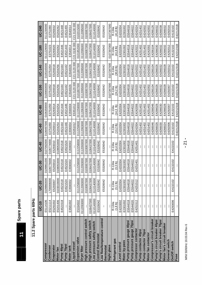
11.2
Spa
re p
arts
60H
z
UC
-10
UC
-20
UC
-30
UC
-40
UC
-60
UC
-80
UC
-100
U
C-1
40
UC
-180
U
C-2
40
Com
pres
sor
E51
1410
6 01
0986
0000
01
0986
1000
01
0709
2000
0106
4970
00
0106
3590
00
0100
6500
00
0100
1650
00
0111
2290
00
0111
2300
00
Con
dens
er
E52
1111
4 L7
0000
6000
01
0677
6000
01
0677
4000
E37
5105
0 E
3751
050
E37
5105
2 E
3751
054
E37
5102
3 E
3751
060
Evap
orat
or
E52
9100
2 E
5293
007
E52
9301
0 E
5293
010
E52
9301
4 E
5293
014
E52
9301
8 E
5293
018
E52
9302
0 E
5293
032
Mot
or fa
n E
5201
406
0103
0190
00
0108
0530
00
0108
0530
00E
5204
254
E52
0425
4 E
5204
256
E52
0425
6 E
5204
262
E52
0426
2 Pu
mp
40ps
i E
4521
518
E45
2151
8 E
4521
518
E45
2151
8 E
4521
444
E45
2144
4 E
4521
444
E45
2144
4 E
4521
446
E45
2144
8 Pu
mp
70ps
i ---
E
4521
524
E45
2152
4 E
4521
524
E45
2144
6 E
4521
446
E45
2144
2 E
4521
442
E45
2144
3 E
4521
455
Wat
er ta
nk
E35
8100
2 E
3590
002
E35
9000
2 E
3590
002
E35
9000
4 E
3590
004
E35
4002
6 E
3540
026
E35
4001
4 E
3540
014
Liqu
id v
esse
l ---
---
---
---
E
5351
012
E53
5101
2 C
21 0
129
000
C21
012
9 00
0C
21 0
130
000
C21
013
0 00
0 Ex
pans
ion
valv
e E
5334
502
0112
2580
00
0112
2580
00
0112
2580
0001
1225
9000
01
1225
9000
01
0180
7000
01
0180
7000
01
0185
2000
01
0201
5000
D
ryer
filte
r 01
1209
3000
01
1209
3000
01
1209
3000
01
1209
3000
0112
0630
00
0112
0630
00
0112
0950
00
0112
0950
00
0112
0950
00
0112
0950
00
Hig
h pr
essu
re c
ontr
ol s
witc
h ---
01
0308
7000
01
0308
7000
01
0308
7000
0103
0870
00
0103
0870
00
0103
0870
00
0103
0870
00
0103
0870
00
0103
0870
00
Hig
h pr
essu
re s
afet
y sw
itch
0106
4370
00
0106
4370
00
0106
4370
00
0106
4370
0001
0643
7000
01
0643
7000
01
0643
7000
01
0643
7000
01
0643
7000
01
0643
7000
Lo
w p
ress
ure
safe
ty s
witc
h 01
1014
0000
01
1014
0000
01
1014
0000
01
1014
0000
0110
1400
00
0110
1400
00
0110
1400
00
0110
1400
00
0110
1400
00
0110
1400
00
Con
trol
ther
mos
tat
E53
2604
2 E
5326
042
E53
2604
2 E
5326
042
E53
2604
2 E
5326
042
E53
2604
2 E
5326
042
E53
2604
2 E
5326
042
Low
flow
/tem
pera
ture
con
trol
th
erm
osta
t --
E53
2604
2 E
5326
042
E53
2604
2 E
5326
042
E53
2604
2 E
5326
042
E53
2604
2 E
5326
042
E53
2604
2
Sigh
t gla
ss
---
---
---
---
---
---
0107
3970
00
0107
3970
00
0107
3970
00
0107
3970
00
Ref
riger
ant g
as
R-1
34a
(1,8
lb)
R-1
34a
(3,1
lb)
R-1
34a
(3
,3 lb
) R
-134
a
(4,4
lb)
R-1
34a
(1
3,2
lb)
R-1
34a
(14,
3 lb
) R
-134
a
(24,
2 lb
) R
-134
a
(30,
8 lb
) R
-134
a
(41,
8 lb
) R
-134
a
(41,
8 lb
) Le
vel c
ontr
ol
E42
0300
2 E
4202
004
E42
0200
4 E
4202
004
E42
0200
4 E
4202
004
E42
0200
4 E
4202
004
E42
0200
4 E
4202
004
Wat
er b
y-pa
ss
E23
0100
2 E
2301
002
E23
0100
2 E
2301
002
E23
0100
2 E
2301
002
E23
0100
2 E
2301
002
E23
0100
2 E
2301
002
Pum
p pr
essu
re g
auge
40p
si
E55
4401
8 E
5544
018
E55
4401
8 E
5544
018
E55
4401
8 E
5544
018
E55
4401
8 E
5544
018
E55
4401
8 E
5544
018
Pum
p pr
essu
re g
auge
70p
si
E55
4402
0 E
5544
022
E55
4402
2 E
5544
022
E55
4402
2 E
5544
022
E55
4402
2 E
5544
022
E55
4402
2 E
5544
022
Com
pres
sor c
onta
ctor
E
4251
512
E42
5151
2 E
4251
401
E42
5140
1 E
4242
004
E42
4200
6 E
4242
020
E42
4202
2 E
4242
022
E42
4202
4 Pu
mp
cont
acto
r 40p
si
---
---
---
---
E42
5140
2 E
4251
402
E42
5140
2 E
4251
402
E42
5140
2 E
4251
402
Pum
p co
ntac
tor 7
0psi
---
---
---
---
E
4251
402
E42
5140
2 E
4251
402
E42
5140
2 E
4251
402
E42
4200
2 M
otor
fan
cont
acto
r ---
---
---
---
E
4251
402
E42
5140
2 E
4242
002
E42
4200
2 E
4242
002
E42
4200
2 C
ompr
esso
r's c
ircui
t bre
aker
---
---
---
---
E
4266
046
E42
6604
6 E
4266
104
E42
6610
4 E
4266
104
E42
6612
6 Pu
mp'
s ci
rcui
t bre
aker
40p
si
---
---
---
---
E42
6602
6 E
4266
026
E42
6602
6 E
4266
026
E42
6603
0 E
4266
032
Pum
p's
circ
uit b
reak
er 7
0psi
---
---
---
---
E
4266
030
E42
6603
0 E
4266
032
E42
6603
2 E
4266
032
E42
6603
8 M
otor
fan'
s ci
rcui
t bre
aker
---
---
---
---
E
4266
024
E42
6602
6 E
4266
028
E42
6602
8 E
4266
032
E42
6603
2 G
ener
al s
witc
h ---
---
---
---
E
4292
006
E42
9200
7 E
4292
007
E42
9201
2 E
4292
012
E42
9201
6 O
n/O
ff sw
itch
E42
9300
6 E
4132
102
E41
3210
2 E
4132
102
E41
3210
2 E
4132
102
E41
3210
2 E
4132
102
E41
3210
2 E
4132
102
Fuse
---
---
---
---
E
4221
231B
E
4221
231B
E
4221
231B
E
4221
231B
E
4221
231B
E
4221
231B
MIN
I 50/
60H
z 19
.03.
04 R
ev 6

-
- 22
12
Te
chni
cal d
iagr
ams
12.1
Dim
ensi
onal
she
et:
UC
Min
i 50H
z
a
Wei
ght (
kg)
A B
C
D
E F
G
H
I J
K L
M
N
O
P U
C
Wat
er
conn
ectio
n ST
SP
m
mm
m
mm
mm
mm
mm
mm
m
mm
mm
m
mm
mm
m
mm
mm
mm
m00
10
3/8'
' -
60
0 63
2 60
0
330
254
0 0
0 52
0 0
0 0
0 0
415
0020
1/
2''
100
115
0 89
0 65
80
34
528
20
0 0
630
0 0
0 0
0 53
000
30
1/2'
' 10
5 12
0 0
1120
65
80
580
275
0 0
0 71
3 0
0 0
0 0
584
0040
1/
2''
110
125
0 11
2065
80
58
027
50
0 0
713
0 0
0 0
0 58
400
60
3/4'
' 16
5 18
5 12
011
3590
10
535
052
678
90
54
488
0 12
088
8 15
263
369
080
000
80
3/4'
' 18
0 20
0 12
011
3590
10
535
052
678
90
54
488
0 12
088
8 15
263
369
080
001
00
1''
215
235
120
1235
90
130
340
550
78
90
654
990
120
989
115
786
735
845
0140
1'
' 23
5 26
0 12
012
3590
13
034
055
078
90
65
499
0 12
098
9 11
578
673
584
501
80
1''
345
375
120
1635
90
130
343
722
78
90
804
1140
110
1400
85
990
840
950
0240
1'
' 36
4 40
0 12
016
3590
13
034
372
278
90
80
411
4011
014
0085
99
084
095
0
B
F E
L
C
K
D
I O
P
G H
M
N
J
A
MIN
I 50/
60H
z 19
.05.
03 R
ev. 5

-
- 23
12
Te
chni
cal d
iagr
ams
U
C M
ini 6
0Hz
W
eigh
t (lb
) A
B C
D
E
F G
H
I
J K
L M
N
O
P
UC
W
ater
co
nnec
tion
ST
SP
in
in
in
in
in
in
in
in
in
in
in
in
in
in
in
in
0010
3/
8''
- 13
2 0
25
2 0
13
10
0 0
0 20
0
0 0
0 0
16
0020
1/
2''
220
254
0 35
3
3 14
11
0
0 0
25
0 0
0 0
0 21
00
30
1/2'
' 23
1 26
5 0
44
3 3
22
11
0 0
0 28
0
0 0
0 0
23
0040
1/
2''
243
276
0 44
3
3 22
11
0
0 0
28
0 0
0 0
0 23
00
60
3/4'
' 36
4 40
8 5
45
4 4
14
21
3 4
21
35
5 35
6
25
27
31
0080
3/
4''
397
441
5 45
4
4 14
21
3
4 21
35
5
35
6 25
27
31
01
00
1''
474
518
5 49
4
5 13
22
3
4 26
39
5
39
5 31
29
33
01
40
1''
518
573
5 49
4
5 13
22
3
4 26
39
5
39
5 31
29
33
01
80
1''
761
827
5 64
4
5 14
28
3
4 32
45
4
55
3 39
33
37
02
40
1''
805
882
5 64
4
5 14
28
3
4 32
45
4
55
3 39
33
37
MIN
I 50/
60H
z 19
.05.
03 R
ev. 5
B
F E
L
C
K
D
I O
P
G H
M
N
J
A

E-4
M3
PZA
B6
TC
TCI
B7
PI I-1
E-2
F-1
M2
V-1
E-1
L
PC
PZA B5
H
LSA
B4
TCI
P1
E-3
LI I-2
A B CV-3H
V-5
V-6
V-8
E-5
V-9
M1 R1
E-6
EF0
010S
P.vs
d
PS B1
V-1
0
D-1
D-2
PI I-3
V-4
PI I-4
V-7
V-2
H
TAG
TAG
TAG
TAG
E-1
Wat
er b
y-pa
ss w
ith c
alib
rate
d or
ifice
I-2Le
vel i
ndic
ator
P1C
ontro
l the
rmos
tat
R1
Cra
nk-c
ase
heat
er (f
rom
UC
-60
to U
C-2
40)
E-2
Wat
er -
freon
eva
pora
tor
I-3/4
pres
sure
gau
ges
(UC
-100
to U
C-2
40)
M1
Freo
n co
mpr
esso
rA
E-3
D-1
/2V
ibra
tion
adju
ster
M2
BE-
4Fr
eon
cond
ense
rB
1S
peed
regu
lato
r con
trolle
rM
3C
Dra
in (f
rom
UC
-10
to U
C-4
0)E-
5Si
ght g
lass
(fro
m U
C-1
40 to
UC
-240
)B
4V-
1E-
6Si
ght g
lass
- oi
l lev
el (f
rom
UC
-40
to U
C-2
40)
B5
Hig
h pr
essu
re s
afet
y sw
itch
V-2
Man
ual v
alve
(fro
m U
C-6
0 to
UC
-240
)F-
1B
6Lo
w p
ress
ure
safe
ty s
witc
hV-
3D
rain
man
ual v
alve
(fro
m U
C-6
0 to
UC
-240
)I-1
Wat
er p
ress
ure
gaug
eB
7Lo
w fl
ow /
tem
pera
ture
con
trol t
herm
osta
V-4/
10Sc
hrad
er v
alve
Filte
r dry
er
DES
CR
IPTI
ON
DES
CR
IPTI
ON
DES
CR
IPTI
ON
DES
CR
IPTI
ON
Wat
er ta
nkP
ump
Leve
l sw
itch
Mot
or fa
n
Filli
ng ta
bO
verfl
ow ta
b
Expa
nsio
n va
lve

PS B1
PZA
B6
TC
TCI
B7
PI
I-1
E-2
F-1
V-1
L
PC
V-1
0
PZA
B5H
TCI
P1
V-5
V-6
V-8
E-6
V-9
M1 R1
E7
EF00
10S
T.vs
d
D-2
D-1
PI
I-2
V-4
PI I-3
V-7
E-4
M3
V-2
H
TAG
TAG
TAG
TAG
E-2
P1B
5M
3E-
4I-1
B6
V-1
E-6
I-2/3
B7
V-2
E-7
D-1
/2R
1V-
4/10
F-1
B1
M1
DES
CR
IPTI
ON
DES
CR
IPTI
ON
DES
CR
IPTI
ON
DES
CR
IPTI
ON
Freo
n co
mpr
esso
r
Wat
er p
ress
ure
gaug
eFr
eon
cond
ense
rW
ater
- fre
on e
vapo
rato
r
Pre
ssur
e ga
uges
(UC
-100
to U
C-2
40)
Con
trol t
herm
osta
t
Filte
r dry
erS
chra
der v
alve
Low
flow
/ te
mpe
ratu
re c
ontro
l the
rmos
tat
Sig
ht g
lass
Sig
ht g
lass
-oil
leve
l (fro
m U
C-4
0 to
UC
-240
)H
igh
pres
sure
con
trol s
witc
h (e
xcep
t UC
-10)
Hig
h pr
essu
re s
afet
y sw
itch
Low
pre
ssur
e sa
fety
sw
itch
Cra
nk-c
ase
heat
er (f
rom
UC
-60
to U
C-2
40)
Mot
or fa
nE
xpan
sion
val
veM
anua
l val
ve (f
rom
UC
-60
to U
C-2
40)
Vib
ratio
n ad
just
er (f
rom
UC
-140
to U
C-2
40)