DONGLE DATABASE AND GUI FOR MANAGING UNIQUE BIRD TAD IDS A Design Project Report Presented to the School of Electrical and Computer Engineering of Cornell University in Partial Fulfilment of the Requirements for the Degree of Master of Engineering, Electrical and Computer Engineering Submitted by Di Jiang, Jinghan Du, Lei Zhang, Rui Meng MEng Field Advisor: Joe Skovira MEng Outside Advisor: David W Winkler Degree Date: January 2017
Transcript
DONGLE DATABASE AND GUI
FOR MANAGING UNIQUE
BIRD TAD IDS
A Design Project Report
Presented to the School of Electrical and Computer
Engineering of Cornell University
in Partial Fulfilment of the Requirements for the Degree of
Master of Engineering, Electrical and Computer Engineering
Submitted by
Di Jiang, Jinghan Du, Lei Zhang, Rui Meng
MEng Field Advisor: Joe Skovira
MEng Outside Advisor: David W Winkler
Degree Date: January 2017
Abstract
Master of Engineering Program
School of Electrical and Computer Engineering
Cornell University
Design Project Report
Project Title: Dongle Database and GUI for Managing Unique Bird Tag IDs
Authors: Di Jiang(dj327), Jinghan Du(jd855), Lei Zhang(lz392), Rui
Meng(rm879).
Abstract: Our project is an interdisciplinary project including Biology and ECE
fields. Our team has 4 members and we are responsible for the ECE part. First of
all, we developed a USB dongle containing a receiver to detect tag codes and a
GPS receiver to record location. As for the tag part, we designed a new tag with
a smaller solar beeper which can utilize the solar energy more efficiently. In
addition, we also extended and refined the GUI and its interaction with the cloud-
based database.
After the project is finished, field biologists can use this device with a laptop
computer to capture tag codes, times and locations as they are deployed, along
with species and band number of the animals being tagged. Whenever a tag ID
is recovered through RF communication in the field, similar data will be recorded
and stored to the cloud-based database. It is a very meaningful project for
protecting the endangered birds. What’s more, this project can also be applied to
other endangered animals.
Personal Contributions:
Jinghan Du: 1. Dongle programming The dongle need to be programmed to listen to the tag IDs and send those information to the user’s computer. There were several possible solutions for this problem. One of them is to write a completely new function on the board to make the board listen to the signals. Also, the board could transmit all the information it heard in the buffer to the computer or it can send only the tag IDs. Here I chose to write to code in the default functions given by the board demo. Since the board can listen to the signals at the specified frequency, I just need to let it send what it heard to the computer. This is the simplest way as far as I can see, and it is easy to debug. As for the information to send. I found there was a buffer to store all the message the board had received. And the information about the tag ID is always stored in a fixed place in the buffer. So I programmed to let it only send those tag IDs to the computer. In this way, the dongle is only transmitting useful information. 2. Dongle layout refinement The overall size of the dongle must be smaller so that users could take it with them. Thus a new dongle with only the useful parts of the old board (Si1060 and a USB/serial adapter) needs to be designed. The Si1060 developer board has a lot of elements that we don’t need, such as the LED lights. Basically there are two choices about how to simplify this: either we only take out the Si1060 chip or we combine Si1060 and USB/Serial adapter together. The former choice would definitely make the new dongle smaller than the later one. But with a USB interface, the new dongle could be easily tested without connecting to another USB/serial adapter. On the other hand, USB port might not be useful when the dongle is combined with the Raspberry-Pi. We designed the new dongle with the USB/serial adapter. Because one of the functions of the dongle is to be plugged into the computer to send data to GUI. Thus the USB/serial adapter is indispensable. 3. Tag layout refinement The current tag is working fine but we can still make changes to its board to make it have a wider range of frequency and a longer signal transmission distance. Achieve this, the board has to utilize solar energy in a more efficient way. We chose the si1060 RF chip finally. Because in this way, we can use the same chip on RF Dongle. The chip can also support a wide range of operating frequencies so we can use it for the current 434 MHz design and also for tags and base stations that will operate at 166 MHz for the wildlife tracking system. As
for the board layout design, we used double layer on the tag so that those elements can fit into a board as small as a dime. All of the detailed documentation of design implementation and final results of the above problems are discussed below.
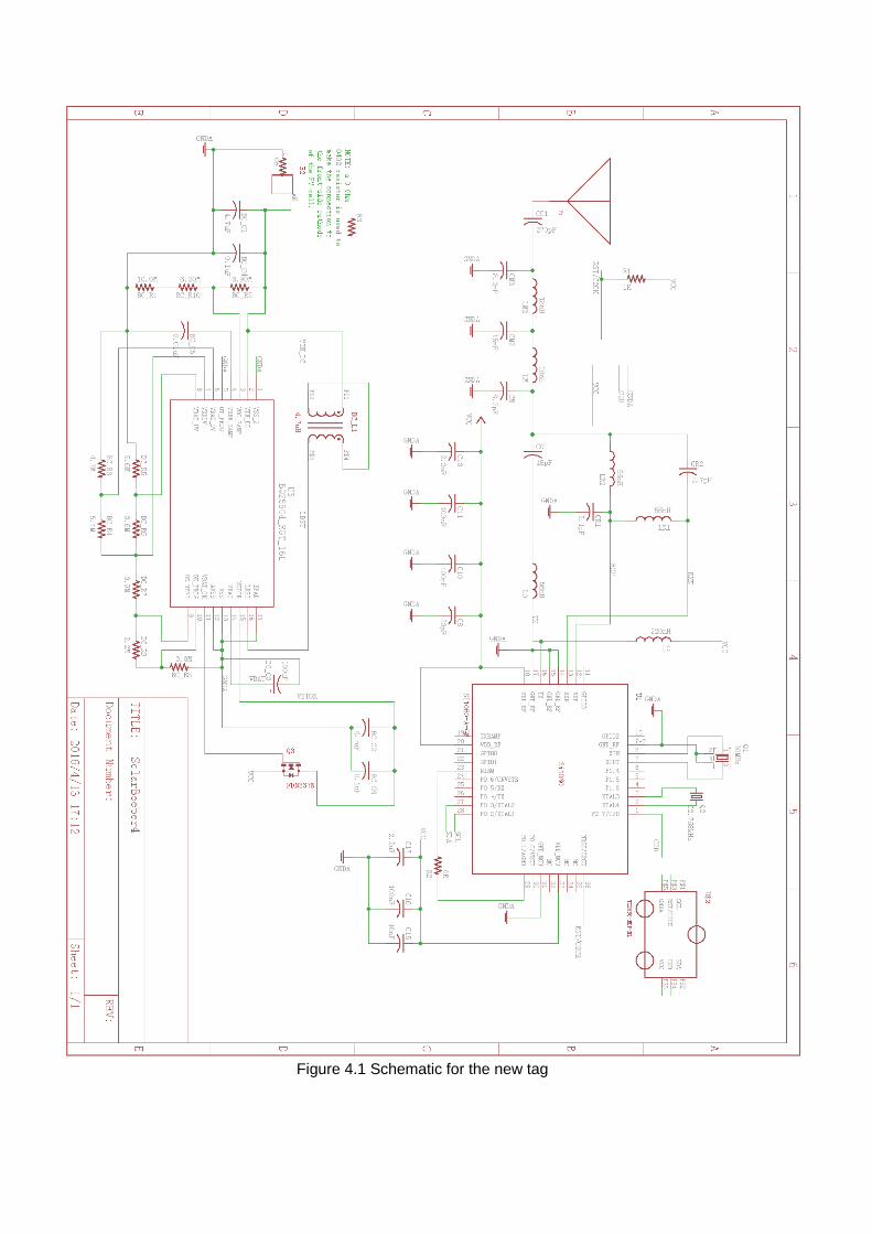
Lei Zhang: 1. Regular expression programming For the tagID received from the tag and the GPS coordinate information received from the GPS module, we need to check the format of the information before sending the information to GUI. Because we need to make sure the information is in standard format and we need to violate hackers’ attack for security reasons. Therefore, we must figure out the way to check the format of the information. After sincere consideration, we chose Regular Expression to check the format of the information. Because this is an easy and general way to examine the format of data. However, there were several ways to implement regular expression, for example, we can program on the Dongle part and check the information after receiving the information to Dongle, and then send the information of good format to GUI. We can also program on the GUI part to examine the format. In order to improve the efficiency of our system and make our system more robust, I chose to program on the GUI part, because programming on software part is more stable and easy to debug. In this way, our system is much more robust. And I parsed the tagID and GPS coordinate into several parts according to the standard formats, separating them according to the position of numbers or letters. After the Dongle received the information, we will use the regular expression to examine the format and only send the good-formatted information to GUI. 2. Dongle layout refinement We combined the si1060 and USB/Serial adapter together to make the Dongle, however, the Dongle is too big in this way, and it is not easy for ecologists to take it to the fields. So we extracted the most useful parts from the old Dongle and then designed the new Dongle with smaller size. There are two ways about how to simplify the Dongle, one solution is that we only take the RF chip on si1060 and abandoned the USB part, in this way the Dongle will be much smaller. The other way is to keep the USB part and the Dongle will be a little bigger. After cautious consideration and heated discussion, we chose to keep the USB part. Because it is easy to test the Dongle with a USB interface, we do not need to use other USB adapters. Also, the users of the Dongle can simply plug the Dongle in their laptops easily. What’s more, when we combine the Dongle with the Raspberry-Pi, the USB port is convenient as well. 3. New tag layout design The original tag works pretty well at present, but we want the tag to listen to a wider frequency and transmit RF signal in a longer distance as well. So we decided to design a new tag.
Di Jiang: 1. Design and program from the prototype of GUI The first task I received for this project is creating a GUI for bird tag information management. I construct two basic interface to implement login and information display function. I used simple label, textField and button to construct the interface, FlowLayOut to display these components. The login interface could parse the username and password and switch to information display.
The information display interface has three buttons, both display and recover buttons could receive the GPS information and tagID from GPS module and Si1060, check the format of information and show them in GUI. Submit button could save the information in GUI to a txt file since our team don’t have a server to save information in cloud database.
2. Receive and display GPS information and tagID on GUI When our team could receive tagID from Si1060 and display the tagID in the board, I start to display this information and GPS information from GPS module. Firstly, I use realTerm to test whether I could receive information from dongle and GPS module. Secondly, I write methods using JAVA to open the two ports which connect GPS module and dongle respectively, read the information from two port alternatively. Thirdly, I started to process the data I got. GPS information comes in a format of string starts with GPGGA, I parse the GPS information from the long string and using regular expression to check whether it’s a valid information and transmit it to GUI textfield. Last, I get local time and date from the computer and display them in GUI too when Deploy and Recover button are clicked. When submit button is clicked, I get the string from all text field and combine them to a long string and save them in a local txt file. 3. Test latest version Dongle In the spring semester, our team receive the latest Dongle and I test it with Rui. We programmed and downloaded the code to Dongle and connected Dongle with computer. We used realTerm to test whether Dongle could transmit data and redesigned the connection part with GUI, after fixing bugs with latest Dongle, I started to work on refining GUI. 4. Design and refine GUI according to user’s needs
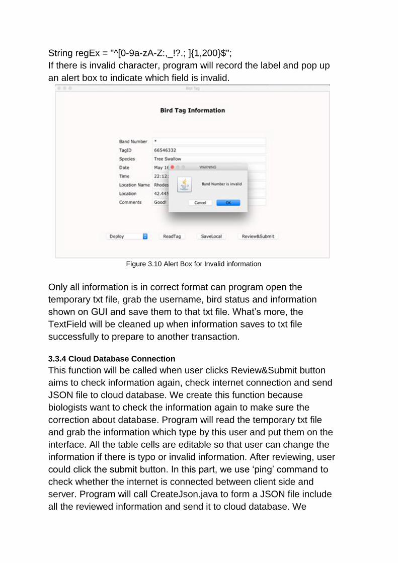
I refined GUI from four aspects, styling, information checking, data management and database connection which I have described in Part 3 GUI and Database Connection. In styling, I pick new font, background color, different layout to reconstruct the interface. In information checking, I step to expand regular expression, parse each information a particular checking format and pop up an alert window if the information is invalid. In data management and database connection, I construct temp txt file and permanent txt file to achieve these functions.
Rui Meng: 1. Transmit GPS and tagID information For Jinghan Du has already successfully transmit GPS and tagID information to laptop, the problem needs to be solved in this part is to transmit these information to the GUI. Because the stream transmitted to the laptop includes information we need and other things we don’t need, I need to find a solution to extract the useful information. The possible solutions are to extract the substring or to combine this with regular expression in JAVA. After testing the two methods, I choose the latter solution for using regular expression can make sure the information are in right format we want so it’s more secure. The specific solution in JAVA is to use substring method and
Pattern and Matcher class in JAVA. The detailed documentation of design implementation and the test result is discussed in 3.3.2. 2. Dongle layout refinement The problem needs to solved in this part is to make a smaller dongle so that it will be easier for the biologists to take it with them. The solution to the problem is to discard the elements we don’t need in Si1060 developer platform and just keep the Si1060 microcontroller. Then we combine it with a USB adapter. The detailed documentation of design implementation is discussed in 2.2.2. 3. Sample dongle test After the schematic and PCB design, we need to test the sample USB dongle to make sure it can detect the tagID information as well as connecting to the laptop. The test method and result are discussed in 2.2.3 and 2.3. Now the USB dongle has been put into manufacture. 4. GUI refinement The problem in this part is to let the biologists to get tagID and GPS information in the GUI and also enter other fields. After checking, these information should be sent to the cloud database. For complete information, we add different text fields; to let the user read tagID, GPS and time information, we add “readtag” button; to make sure the information entered into database are secure, we add the function to check the illegal input; to provide users the chance to correct the typos, we add the review and edit interface; for the consideration of that users may not get access to the Internet all the time, we add the function to save entries to local and check the Internet connection...The detailed documentation of design implementation and test result are discussed in Section 3.
Executive Summary GUI:
1. Accomplishments of GUI: 1. Starting from a simple version of GUI, we programmed on it to receive tagID and GPS
information from the Dongle and GPS receiver and then show them on the textfield.
2. We refined the GUI by adding the areas in the login interface, modifying the fields according
to user’s need in the bird tag information interface.
3. We validate user inputs in the bird tag information interface to avoid illegal inputs.
4. We built the third interface of GUI for users to review and submit. The user can edit any field
of the entries entered by himself/herself.
2. Challenges of GUI:
1. The user needs to get sufficient information from the GUI including the tagID, GPS and time.
2. The user should enter information easily and be able to review and edit the entries he/she
entered.
3. Before submitting to the database, all the fields should be checked to avoid illegal input.
4. The GUI should check the Internet connection and if no connection save entries to local.
Dongle:
1. Accomplishments of Dongle: 1. We programmed on Si1060, a RF microcontroller manufactured by Silicon Labs on which we
programmed on to let it listen to certain radio frequency, get the tagID information and then
transmit to the laptop constantly.
2. We drew the schematic to connect the crucial part of Si1060 with USB port adapter and
arranged their location in the Eagle file, which includes the schematic and the PCB layout of
the board, to package them into a USB Dongle and sent out for prototype.
3. We tested the sample and found the problems. After testing, the USB Dongle is put into
manufacture. The final version of the Dongle is small, convenient to use and works correctly!
2. Challenges of Dongle: 1. The Dongle should listen to the RF signal and receive the tagID constantly. When there are
multiple tags, it should detect all of them among the range.
2. The Dongle should be able to transmit the tagID information into laptop.
3. The Dongle should be as small as possible. It should be a plug-in device for biologist’s
convenience.
Tag:
1. Accomplishments of tag: 1. We changed the RF chip. The new chip can receive, not just transmit, so we can use the
same chip on the RF dongle. The new chip also supports a wider range of operating
frequencies so we can use it for the current 434 MHz design and also for tags and base
stations that will operate at 166 MHz for the wildlife tracking system.
2. We designed the tag using Eagle file, including the schematic and PCB layout.
3. We sent the design file to factory to manufacture the tag and the first version is under testing.
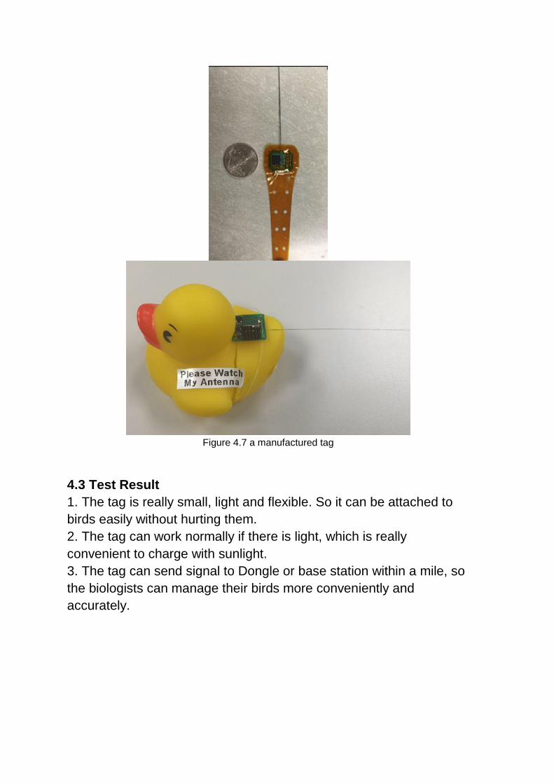
4. The tag’s size is really small, it is just as big as a dime, and the tag can be attached to a bird
like backpack easily. It is really flexible and will not hurt the birds. Besides, the tag can also
utilize the solar energy efficiently.
2. Challenges of tag: 1. Since the tag is attached to birds, it cannot be too big or heavy in case that the birds will be
affected.
2. The solar chip should utilize solar energy efficiently.
3. The RF chip should listen to a wider range of frequencies.
4. If the distance from Dongle or base station is too far, the RF chip could not send signal.
1. Total View of the project
Our system is composed of Dongle, GUI and Tag. And the specific
implementations of each part are explained as follows.
2. Dongle
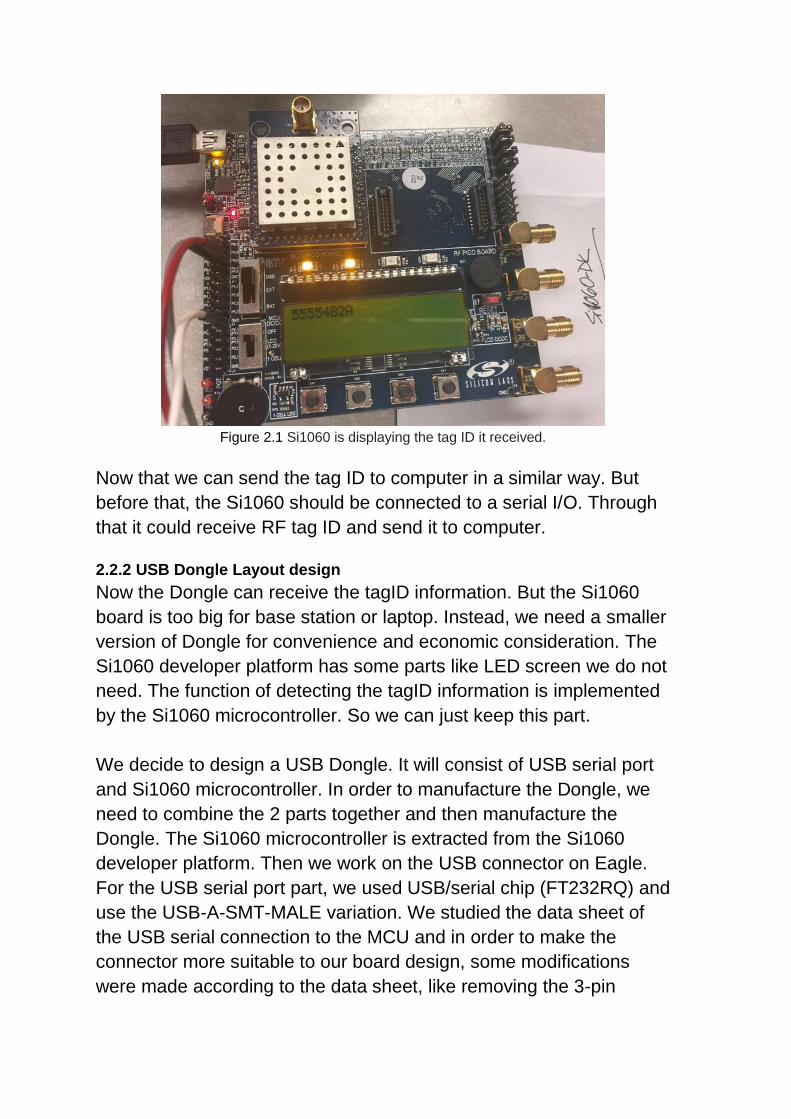
2.1 Objective
The main object of Dongle is to receive tagID information. When a
bird with a tag fly by, we can get the tagID of it. Thus we can track the
birds.
Here we used Si1060 as the dongle board. Silicon Laboratories’