82
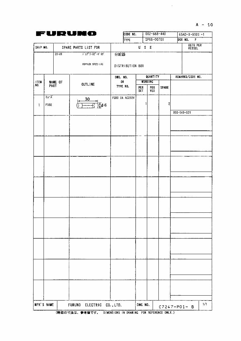
DOPPLER SPEED LOG DS-80 Marine Speed and Distance Measuring Equipment (SDME)
| Date post: | 06-Apr-2018 |
| Category: |
Documents |
| Upload: | phungkhanh |
| View: | 234 times |
| Download: | 3 times |
DOPPLER SPEED LOG
DS-80 Marine Speed and Distance Measuring Equipment (SDME)

Your Local Agent/DealerYour Local Agent/Dealer
9-52 Ashihara-cho,9-52 Ashihara-cho,Nishinomiya, JapanNishinomiya, Japan
Telephone :Telephone : 0798-65-21110798-65-2111Telefax :Telefax : 0798-65-42000798-65-4200
FIRST EDITION :FIRST EDITION : FEB.FEB. 20002000Printed in JapanPrinted in JapanAll rights reserved.All rights reserved.MM :: FEB.FEB. 12,200212,2002
PUB.No.PUB.No. IME-72470-MIME-72470-M*00080889800**00080889800**00080889800**00080889800*(( TATATATA )) DS-80DS-80
* 0 0 0 8 0 8 8 9 8 0 0 ** 0 0 0 8 0 8 8 9 8 0 0 *
*IME72470M00**IME72470M00**IME72470M00**IME72470M00*
* I M E 7 2 4 7 0 M 0 ** I M E 7 2 4 7 0 M 0 *
i
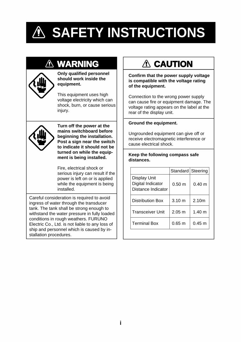
SAFETY INSTRUCTIONS
CAUTIONConfirm that the power supply voltageis compatible with the voltage ratingof the equipment.
Connection to the wrong power supply can cause fire or equipment damage. Thevoltage rating appears on the label at therear of the display unit.
Ground the equipment.
Ungrounded equipment can give off or receive electromagnetic interference orcause electrical shock.
Keep the following compass safe distances.
WARNINGOnly qualified personnelshould work inside theequipment.
This equipment uses high voltage electricity which can shock, burn, or cause serious injury.
Turn off the power at the mains switchboard before beginning the installation.Post a sign near the switch to indicate it should not be turned on while the equip-ment is being installed.
Fire, electrical shock or serious injury can result if the power is left on or is applied while the equipment is being installed.
Display UnitDigital IndicatorDistance Indicator Distribution Box 3.10 m 2.10m Transceiver Unit 2.05 m 1.40 m
Terminal Box 0.65 m 0.45 m
Standard Steering
0.50 m 0.40 m
Careful consideration is required to avoid ingress of water through the transducer tank. The tank shall be strong enough to withstand the water pressure in fully loaded conditions in rough weathers. FURUNO Electric Co., Ltd. is not liable to any loss of ship and personnel which is caused by in-stallation procedures.

ii
TABLE OF CONTENTS
SYSTEM CONFIGURATION................. iii
EQUIPMENT LISTS .............................. iv
1. MOUNTING ........................................ 1
1.1 Category of Equipment ...........................1
1.2 Display Unit ............................................2
1.3 Transceiver Unit......................................3
1.4 Transducer Unit ......................................4
1.5 Distribution Box ....................................12
1.6 Terminal Box (option)............................13
1.7 Digital Indicator, Distance Indicator
(option)................................................13
1.8 Junction Box (option) ............................14
1.9 Dimmer (option)....................................15
1.10 Range Switch Box, Analog Display Unit
(option)................................................15
2. WIRING ............................................ 16
2.1 Precautions for cable Installation...........16
2.2 Wiring of Distribution Box......................17
2.3 Wiring of Transceiver Unit .....................21
2.4 Wiring of Terminal Box ..........................23
2.5 Display Unit (Digital Indicator, Distance
Indicator) ............................................ 24
2.6 Dimmer, Analog Display Unit, Range
Switch Box.......................................... 24
2.7 Grounding............................................ 25
2.8 Wiring Check ....................................... 25
3. SYSTEM SETTINGS ........................26
3.1 Transducer Adjustment ........................ 26
3.2 Setting of System Menu 2 .................... 27
3.3 Checking the Interconnection............... 28
3.4 Setting of the Maximum Speed Range . 29
3.5 Ship's Speed Adjustment...................... 29
3.6 Setting for Analog Display .................... 30
3.7 DIP Switch S4 Settings ........................ 31
4. CHANGING AC POWER TAP ..........33
APPENDIX CALIBRATION ..............AP-1
PACKING LISTS................................. A-1
OUTLINE DRAWINGS........................ D-1
INTERCONNECTION DIAGRAMS..... S-1
iii
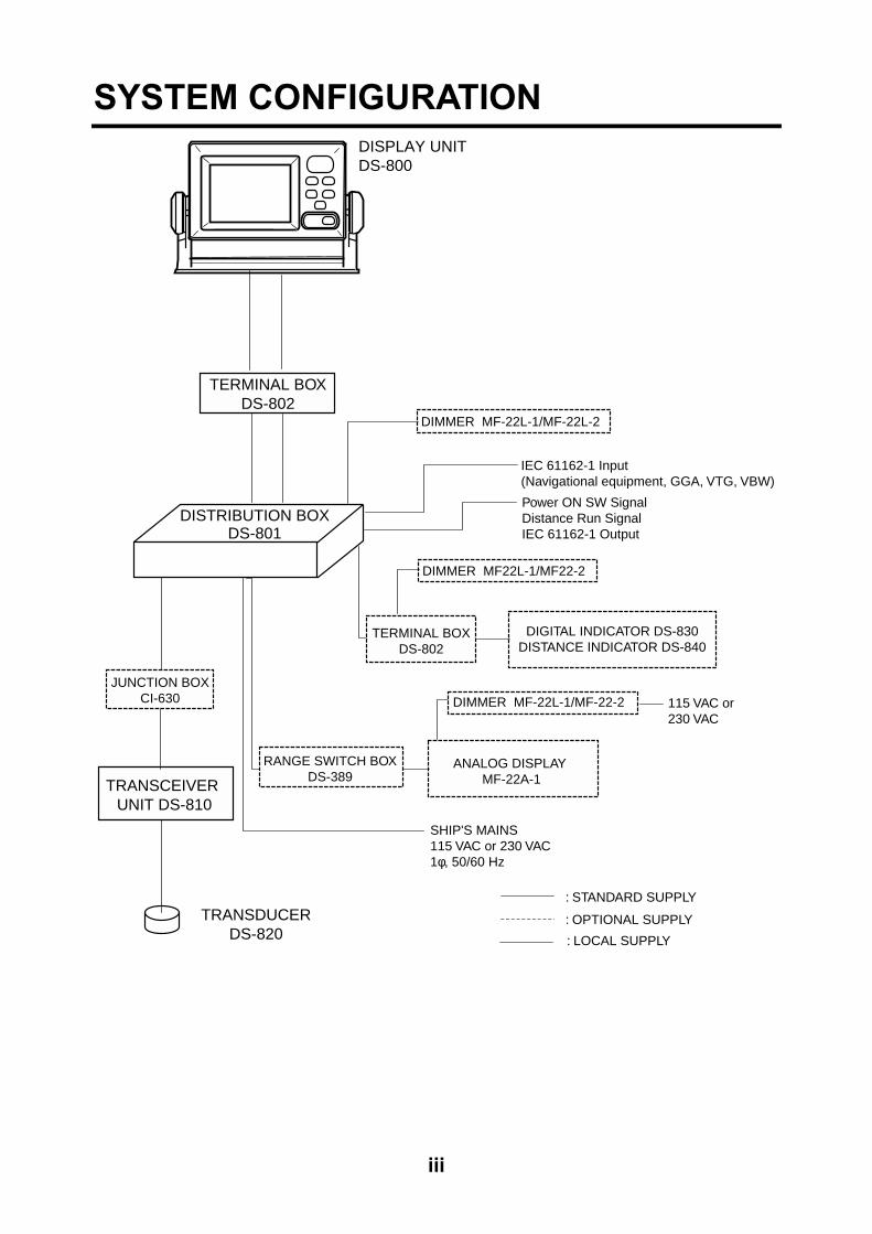
SYSTEM CONFIGURATION
TRANSDUCERDS-820
DISPLAY UNITDS-800
IEC 61162-1 Input (Navigational equipment, GGA, VTG, VBW)
Power ON SW SignalDistance Run SignalIEC 61162-1 Output
DIGITAL INDICATOR DS-830DISTANCE INDICATOR DS-840
: STANDARD SUPPLY
: OPTIONAL SUPPLY
DISTRIBUTION BOXDS-801
TRANSCEIVER UNIT DS-810
DIMMER MF-22L-1/MF-22L-2
TERMINAL BOXDS-802
TERMINAL BOXDS-802
DIMMER MF22L-1/MF22-2
SHIP'S MAINS115 VAC or 230 VAC1φ, 50/60 Hz
RANGE SWITCH BOXDS-389
DIMMER MF-22L-1/MF-22-2
ANALOG DISPLAY MF-22A-1
115 VAC or230 VAC
JUNCTION BOXCI-630
: LOCAL SUPPLY

iv
EQUIPMENT LISTS
Standard supply Name Type Code No. Qty Remarks
Display Unit DS-800 - 1 DS-801-100 - 100 VAC DS-801-110 - 110 VAC DS-801-115 - 115 VAC DS-801-200 - 200 VAC DS-801-220 - 220 VAC
Distribution Box
DS-801-230 -
1
230 VAC Transceiver Unit DS-810 - 1 Transducer Unit DS-820 - 1 with 10/20/30m cable Terminal Box DS-802 - 1 Spare Parts SP65-00700 000-029-046 1 set w/SP65-00701,
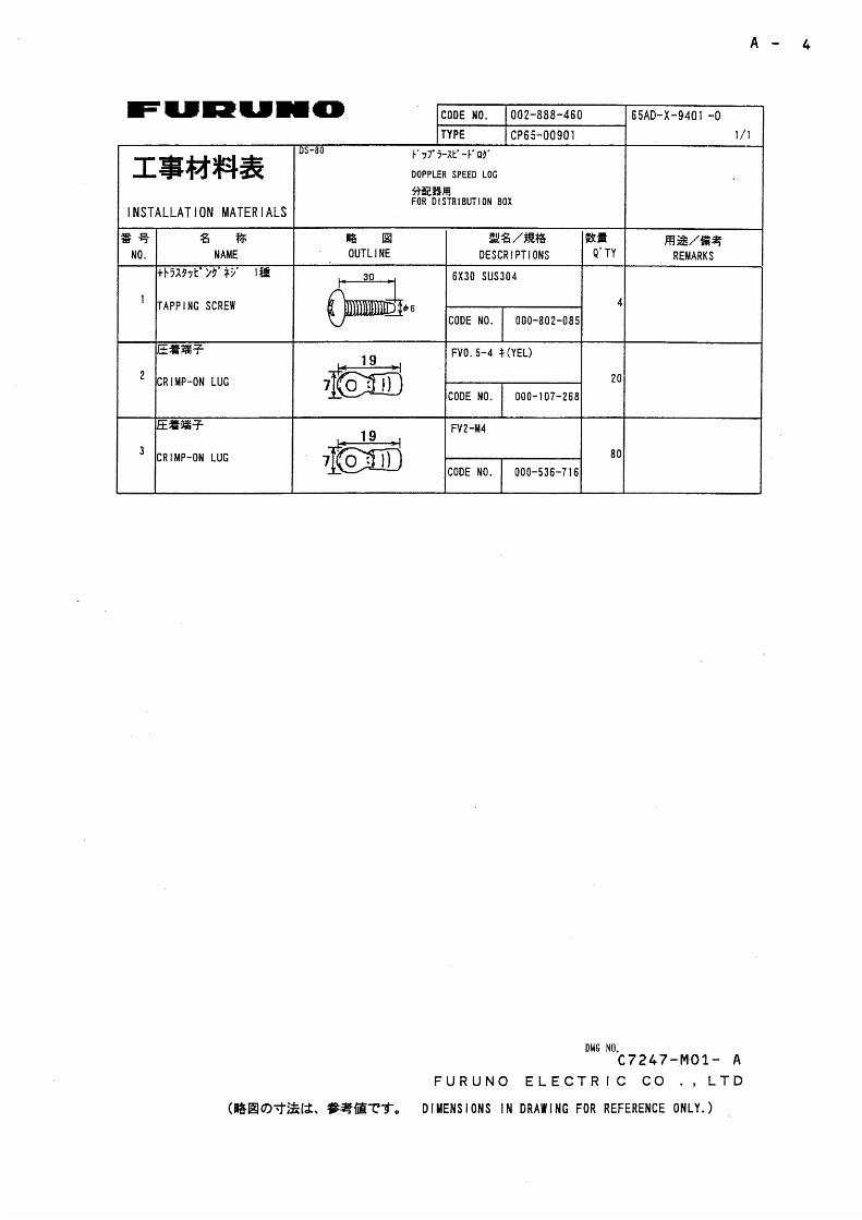
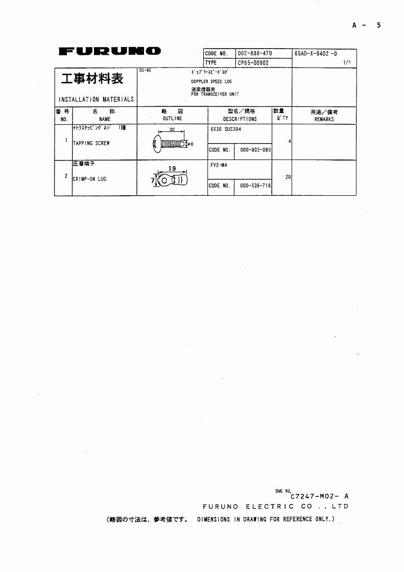
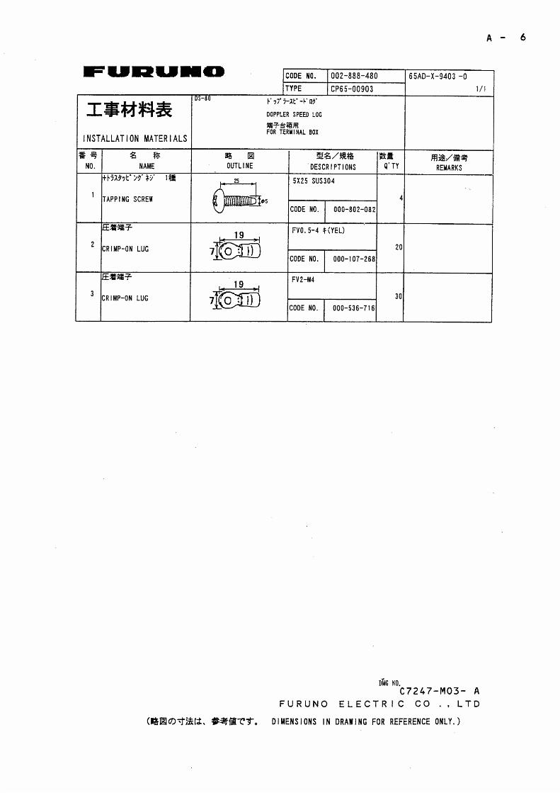
SP65-00702, SP65-00601 Installation Materials CP65-00900 000-029-047 1 set w/CP65-00901,
CP65-00902, CP65-903
Optional equipment
Digital Indicator (000-029-020) Name Type Code No. Qty Remarks
Digital Indicator DS-830 - 1 Spare Parts SP65-00601 002-889-730 1 set Fuse
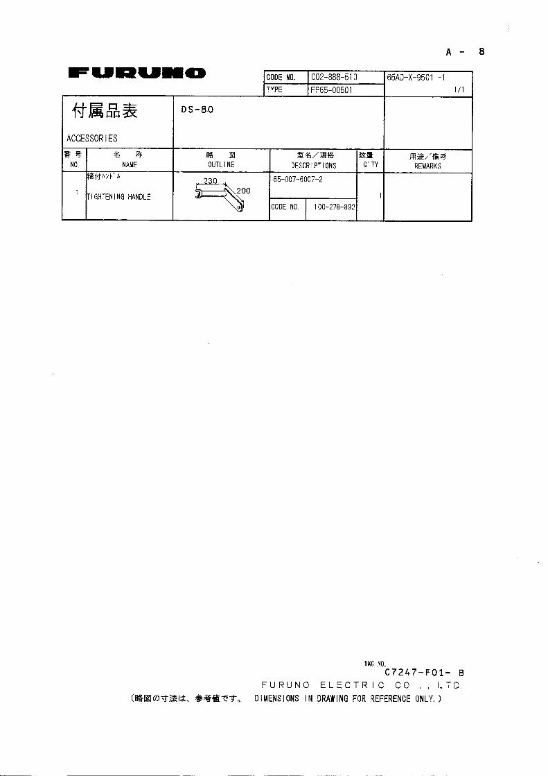
Accessories FP65-00400 000-029-028 1 set FP65-00401, FP65-00402, FP65-00403
Installation Materials CP65-00800 000-029-027 1 set
CP65-00801, MJ-A7SPF-005-020, MJ-A6SPF-003-020
Remote Distance Indicator (000-029-022) Name Type Code No. Qty Remarks
Distance Indicator DS-840 - 1 Spare Parts SP65-00601 002-889-730 1 set Fuse
Accessories FP65-00400 000-029-028 1 set FP65-00401, FP65-00402, FP65-00403
Installation Materials CP65-00800 000-029-027 1 set
CP65-00801, MJ-A7SPF-005-020, MJ-A6SPF-003-020

v
Optional equipment Name Type Code No. Qty Remarks
Terminal Box DS-802 000-029-048 1 set w/CP65-00903 DS-389 000-028-039 1 set w/CP66-01000 MF-22R-1 000-069-391 1 set Flush mount type
Range Switch Box
MF-22R-2 000-069-392 1 set Bulkhead type MF22L-1-100V 000-069-401 1 set flush mount MF22L-1-200V 000-069-402 1 set flush mount MF22L-2-100V 000-069-403 1 set bulkhead
Dimmer
MF22L-2-200V 000-069-404 1 set bulkhead Junction Box CI-630 - 1 set w/CP66-00703
DS-850 000-029-050 1 set w/tightening handle
DS-781 000-029-051 1 set Projection type Through-hull Pipe [TFB-5000 (1)]
DS-782 000-029-052 1 set Gate valve, projection type DS-784 000-029-054 1 set Flush type
Seachest
DS-786 000-029-055 1 set Gate valve type Analog Display MF22A-1 000-069-381 1 set -10 to +30 knots, compact type

This page is intentionally left blank.
1
1 MOUNTING
1.1 Category of Equipment
Equipment for protected area
• Display Unit
• Distribution Box
• Transceiver Unit
• Terminal Box (one standard, other optional)
• Digital Indicator (option)
• Distance Indicator (option)
• Range Switch Box (option)
• Dimmer (option)
• Junction Box (option)
• Analog Display (option)
Equipment to be submerged
• Transducer
2
1.2 Display Unit
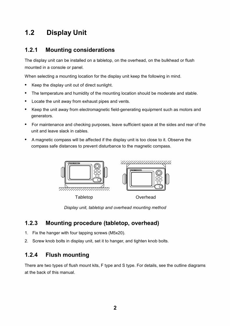
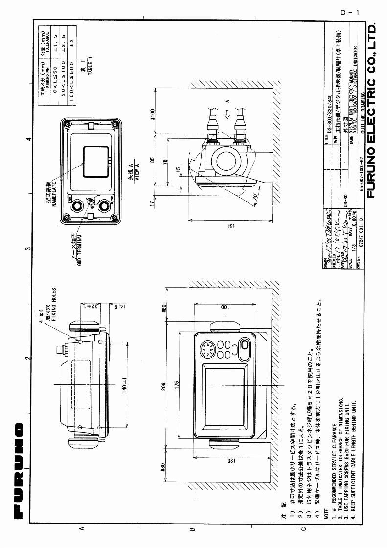
1.2.1 Mounting considerations The display unit can be installed on a tabletop, on the overhead, on the bulkhead or flush mounted in a console or panel.
When selecting a mounting location for the display unit keep the following in mind.
• Keep the display unit out of direct sunlight.
• The temperature and humidity of the mounting location should be moderate and stable.
• Locate the unit away from exhaust pipes and vents.
• Keep the unit away from electromagnetic field-generating equipment such as motors and generators.
• For maintenance and checking purposes, leave sufficient space at the sides and rear of the unit and leave slack in cables.
• A magnetic compass will be affected if the display unit is too close to it. Observe the compass safe distances to prevent disturbance to the magnetic compass.
Tabletop Overhead
Display unit, tabletop and overhead mounting method
1.2.3 Mounting procedure (tabletop, overhead) 1. Fix the hanger with four tapping screws (M5x20).
2. Screw knob bolts in display unit, set it to hanger, and tighten knob bolts.
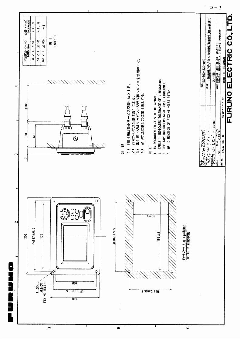
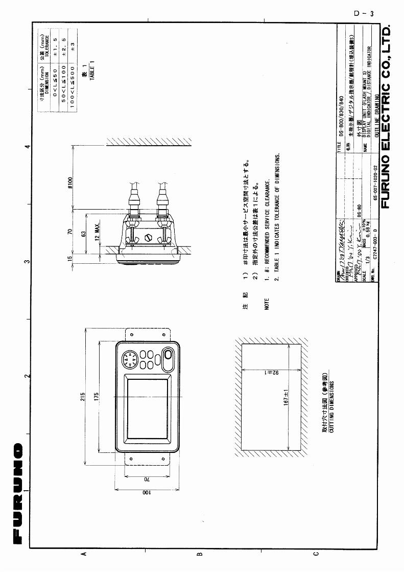
1.2.4 Flush mounting There are two types of flush mount kits, F type and S type. For details, see the outline diagrams at the back of this manual.
3
F type
1. Make a cutout of 167 X 92 mm.
2. Attach the cosmetic panel (supplied) to the display unit with hex bolts (M6X12, supplied) and spring washers (M6, supplied).
3. Fix the display unit to the mounting location with four tapping screws (5X20, supplied).
S type
1. Make a cutout 167 X 92 mm.
2. Attach two fixing metals (supplied) to the display unit with hex bolts (M6X12, supplied) and spring washers (M6, supplied).
3. Screw four wing bolts (supplied) to wing nuts (supplied).
4. Fasten the display unit to the mounting location with four wing bolts and nuts assembled at step 3.
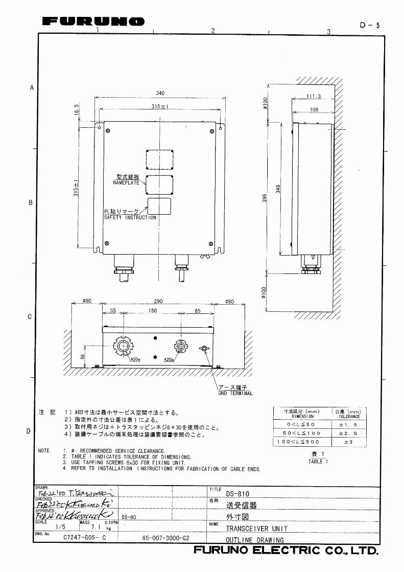
1.3 Transceiver Unit
1.3.1 Mounting considerations • Since the transceiver unit generates heat, install it in a dry, well-ventilated place. The cooling
fans at the top of the unit must not be obstructed, to allow heat to escape.
• This unit is designed for bulkhead mounting to permit dissipation of heat. If bulkhead mounting is absolutely impossible, mount the unit on the floor leaving at least 50 mm clearance between it and the floor to permit dissipation of heat.
• The unit weights 7.1 kg. Reinforce the mounting area, if necessary.
• Leave space around the unit for maintenance and checking. Refer to the drawing at the end of this manual for minimum recommended maintenance space.
• A magnetic compass will be affected if the transceiver unit is placed too close to it. Observe the compass safe distances to prevent disturbance to the magnetic compass.
1.3.2 Mounting procedure Fasten the transceiver unit with four tapping screws (6X30, supplied).
For bulkhead mounting, make sure there is 5 mm clearance between lower edge screw head and bulkhead.
4
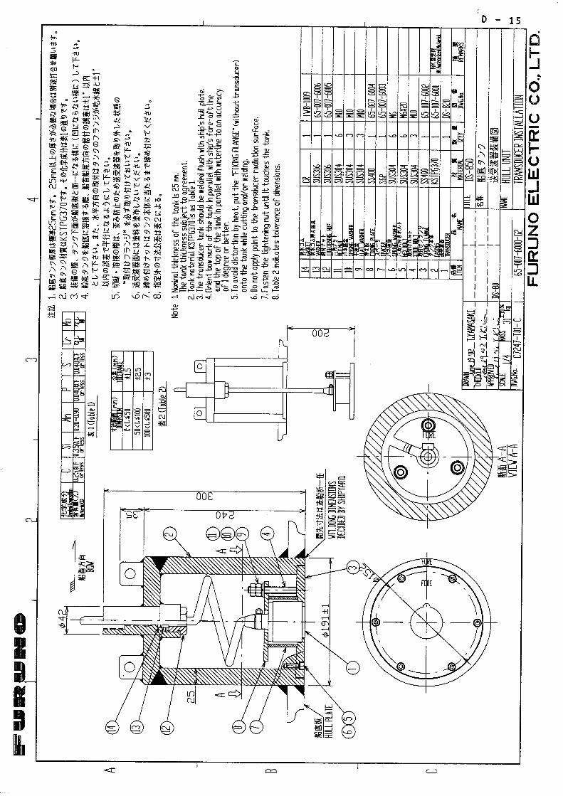
1.4 Transducer Unit The performance of this equipment is directly dependent on the installation of the transducer.
The installation of the transducer and the tank should be accomplished by a dockyard referring to the installation drawings at the later part of this manual.
1.4.1 Mounting Location To decide the location of the transducer, the following points should be taken into account.
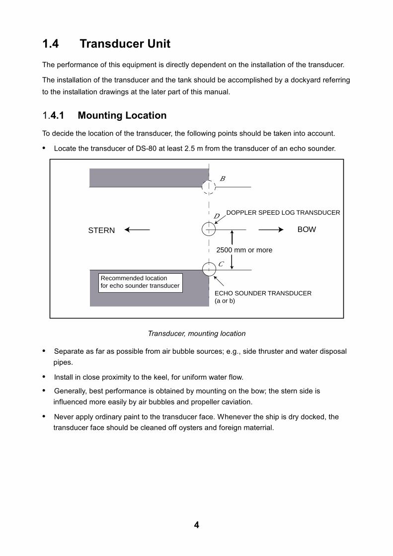
• Locate the transducer of DS-80 at least 2.5 m from the transducer of an echo sounder.
STERN BOW
2500 mm or more
Recommended locationfor echo sounder transducer
ECHO SOUNDER TRANSDUCER(a or b)
DOPPLER SPEED LOG TRANSDUCER
a
c
b
Transducer, mounting location
• Separate as far as possible from air bubble sources; e.g., side thruster and water disposal pipes.
• Install in close proximity to the keel, for uniform water flow.
• Generally, best performance is obtained by mounting on the bow; the stern side is influenced more easily by air bubbles and propeller caviation.
• Never apply ordinary paint to the transducer face. Whenever the ship is dry docked, the transducer face should be cleaned off oysters and foreign materrial.
5
1.4.2 Mounting of transducer
Confirm that a metal cover is attached to the transducer. For seachest except DS-850, remove
the hose clamp from the top of transducer.
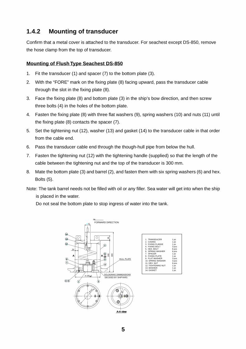
Mounting of Flush Type Seachest DS-850
1. Fit the transducer (1) and spacer (7) to the bottom plate (3).
2. With the “FORE” mark on the fixing plate (8) facing upward, pass the transducer cable
through the slot in the fixing plate (8).
3. Face the fixing plate (8) and bottom plate (3) in the ship’s bow direction, and then screw
three bolts (4) in the holes of the bottom plate.
4. Fasten the fixing plate (8) with three flat washers (9), spring washers (10) and nuts (11) until
the fixing plate (8) contacts the spacer (7).
5. Set the tightening nut (12), washer (13) and gasket (14) to the transducer cable in that order
from the cable end.
6. Pass the transducer cable end through the though-hull pipe from below the hull.
7. Fasten the tightening nut (12) with the tightening handle (supplied) so that the length of the
cable between the tightening nut and the top of the transducer is 300 mm.
8. Mate the bottom plate (3) and barrel (2), and fasten them with six spring washers (6) and hex.
Bolts (5).
Note: The tank barrel needs not be filled with oil or any filler. Sea water will get into when the ship
is placed in the water.
Do not seal the bottom plate to stop ingress of water into the tank.
8
6
12
5 3
191+1
152
42
FO
RE
FO
RE
FO
RE
FO
RE
1. TRANSDUCER 1 pc2. CASING 1 pc3. FIXING FLANGE 1 pc4. FIXING BOLT 3 pcs5. HEX. BOLT 6 pcs6. SPRING WASHER 6 pcs7. SPACER 1 pc8. FIXING PLATE 1 pc9. FLAT WASHER 3 pcs10. SPRING WASHER 3 pcs11. HEX. NUT 6 pcs12. TIGHTENING NUT 1 pc13. WASHER 1 pc14. GASKET 1 pc
FORWARD DIRECTION
A A
A-A viewA-A view
14
13
2
11
10
9
47
1
SOLDERING DIMMENSIONSDECIDED BY SHIPYARD.
HULL PLATE
240
300
35
25
FO
RE
FO
RE
6
See Note on page 6.
(4)
(5)
(7)
(6)
(9)
(10)
(3)
(1)
(8)
(2)
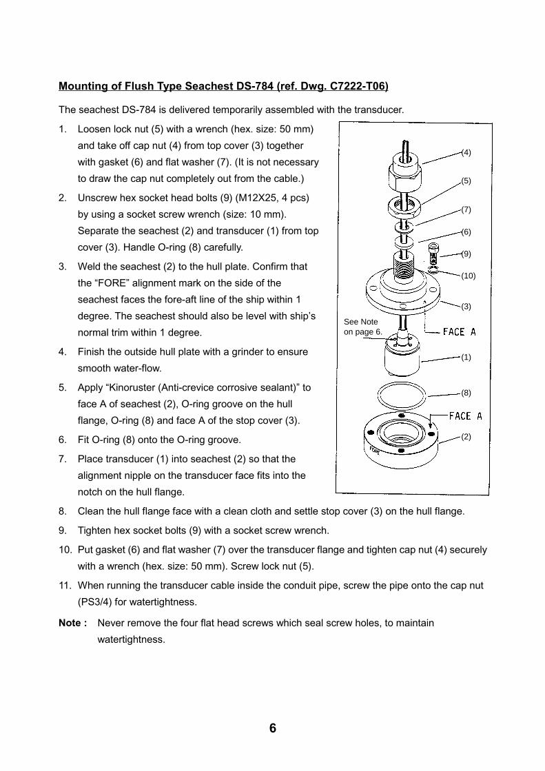
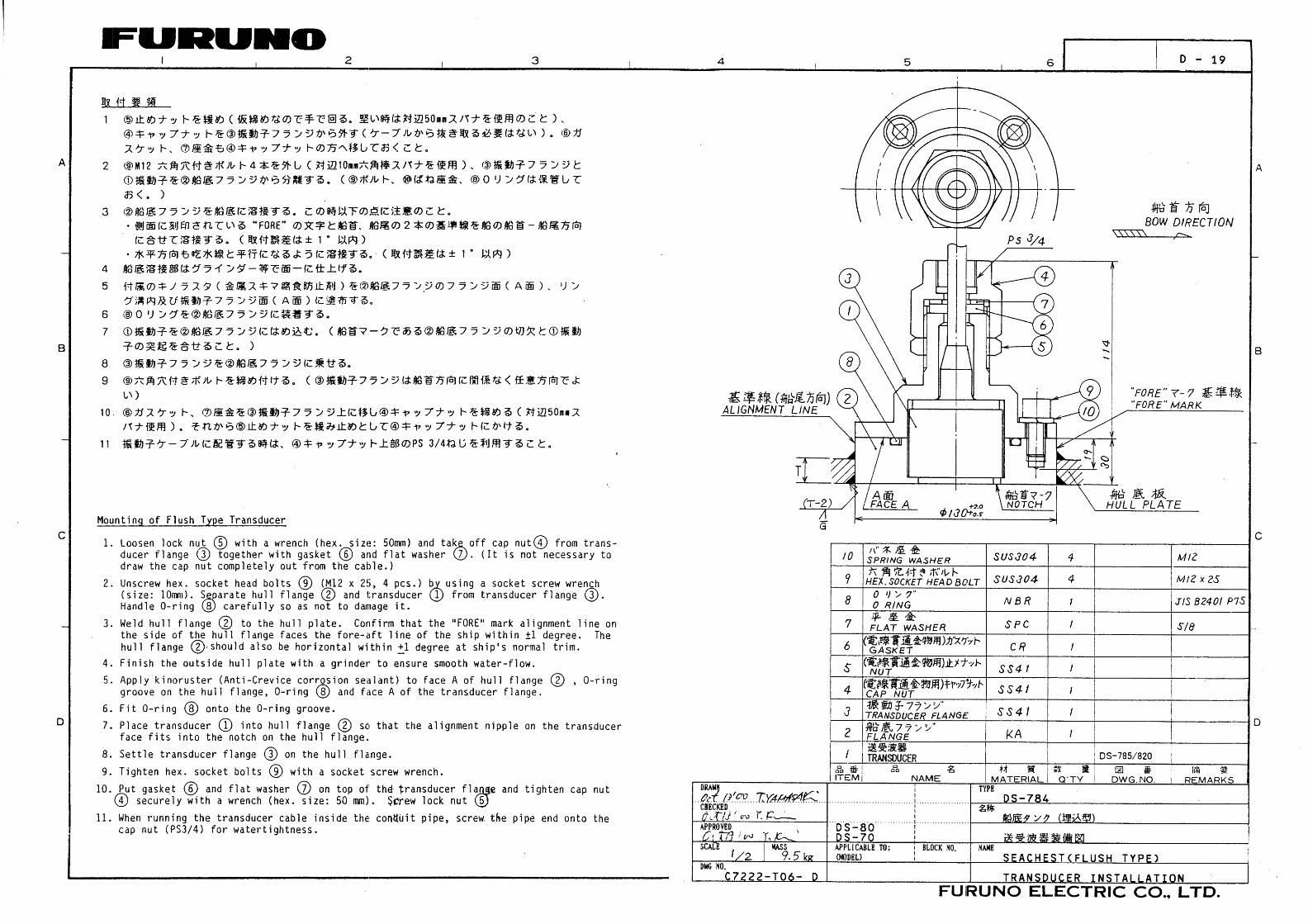
Mounting of Flush Type Seachest DS-784 (ref. Dwg. C7222-T06)
The seachest DS-784 is delivered temporarily assembled with the transducer.
1. Loosen lock nut (5) with a wrench (hex. size: 50 mm)
and take off cap nut (4) from top cover (3) together
with gasket (6) and flat washer (7). (It is not necessary
to draw the cap nut completely out from the cable.)
2. Unscrew hex socket head bolts (9) (M12X25, 4 pcs)
by using a socket screw wrench (size: 10 mm).
Separate the seachest (2) and transducer (1) from top
cover (3). Handle O-ring (8) carefully.
3. Weld the seachest (2) to the hull plate. Confirm that
the “FORE” alignment mark on the side of the
seachest faces the fore-aft line of the ship within 1
degree. The seachest should also be level with ship’s
normal trim within 1 degree.
4. Finish the outside hull plate with a grinder to ensure
smooth water-flow.
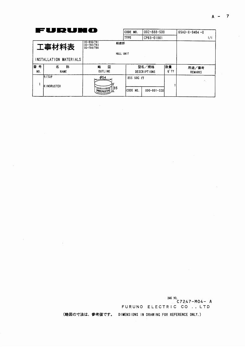
5. Apply “Kinoruster (Anti-crevice corrosive sealant)” to
face A of seachest (2), O-ring groove on the hull
flange, O-ring (8) and face A of the stop cover (3).
6. Fit O-ring (8) onto the O-ring groove.
7. Place transducer (1) into seachest (2) so that the
alignment nipple on the transducer face fits into the
notch on the hull flange.
8. Clean the hull flange face with a clean cloth and settle stop cover (3) on the hull flange.
9. Tighten hex socket bolts (9) with a socket screw wrench.
10. Put gasket (6) and flat washer (7) over the transducer flange and tighten cap nut (4) securely
with a wrench (hex. size: 50 mm). Screw lock nut (5).
11. When running the transducer cable inside the conduit pipe, screw the pipe onto the cap nut
(PS3/4) for watertightness.
Note : Never remove the four flat head screws which seal screw holes, to maintain
watertightness.
7
PS
3/4
129H
ULL P
LATE
130
3024
54
A
R5
48
Bottom View120
A
(4)
(7)
(6)
(5)(9)(10)
(2)(3)
(8)(1)
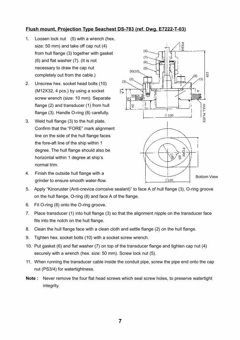
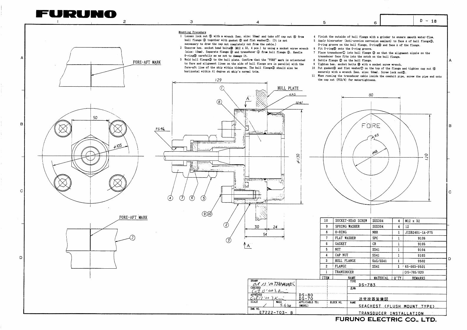
Flush mount, Projection Type Seachest DS-783 (ref. Dwg. E7222-T-03)
1. Loosen lock nut (5) with a wrench (hex.
size: 50 mm) and take off cap nut (4)
from hull flange (3) together with gasket
(6) and flat washer (7). (It is not
necessary to draw the cap nut
completely out from the cable.)
2. Unscrew hex. socket head bolts (10)
(M12X32, 4 pcs.) by using a socket
screw wrench (size: 10 mm). Separate
flange (2) and transducer (1) from hull
flange (3). Handle O-ring (8) carefully.
3. Weld hull flange (3) to the hull plate.
Confirm that the “FORE” mark alignment
line on the side of the hull flange faces
the fore-aft line of the ship within 1
degree. The hull flange should also be
horizontal within 1 degree at ship’s
normal trim.
4. Finish the outside hull flange with a
grinder to ensure smooth water-flow.
5. Apply “Kinoruster (Anti-crevice corrosive sealant)” to face A of hull flange (3), O-ring groove
on the hull flange, O-ring (8) and face A of the flange.
6. Fit O-ring (8) onto the O-ring groove.
7. Place transducer (1) into hull flange (3) so that the alignment nipple on the transducer face
fits into the notch on the hull flange.
8. Clean the hull flange face with a clean cloth and settle flange (2) on the hull flange.
9. Tighten hex. socket bolts (10) with a socket screw wrench.
10. Put gasket (6) and flat washer (7) on top of the transducer flange and tighten cap nut (4)
securely with a wrench (hex. size: 50 mm). Screw lock nut (5).
11. When running the transducer cable inside the conduit pipe, screw the pipe end onto the cap
nut (PS3/4) for watertightness.
Note : Never remove the four flat head screws which seal screw holes, to preserve watertight
integrity.
8
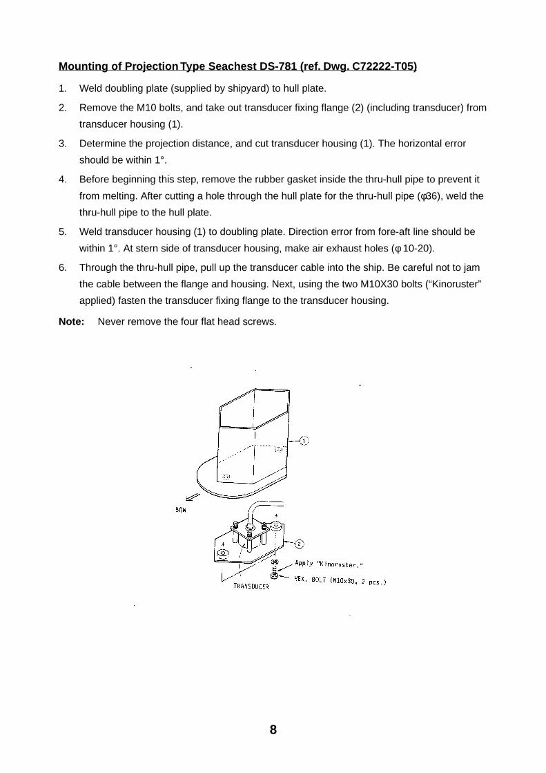
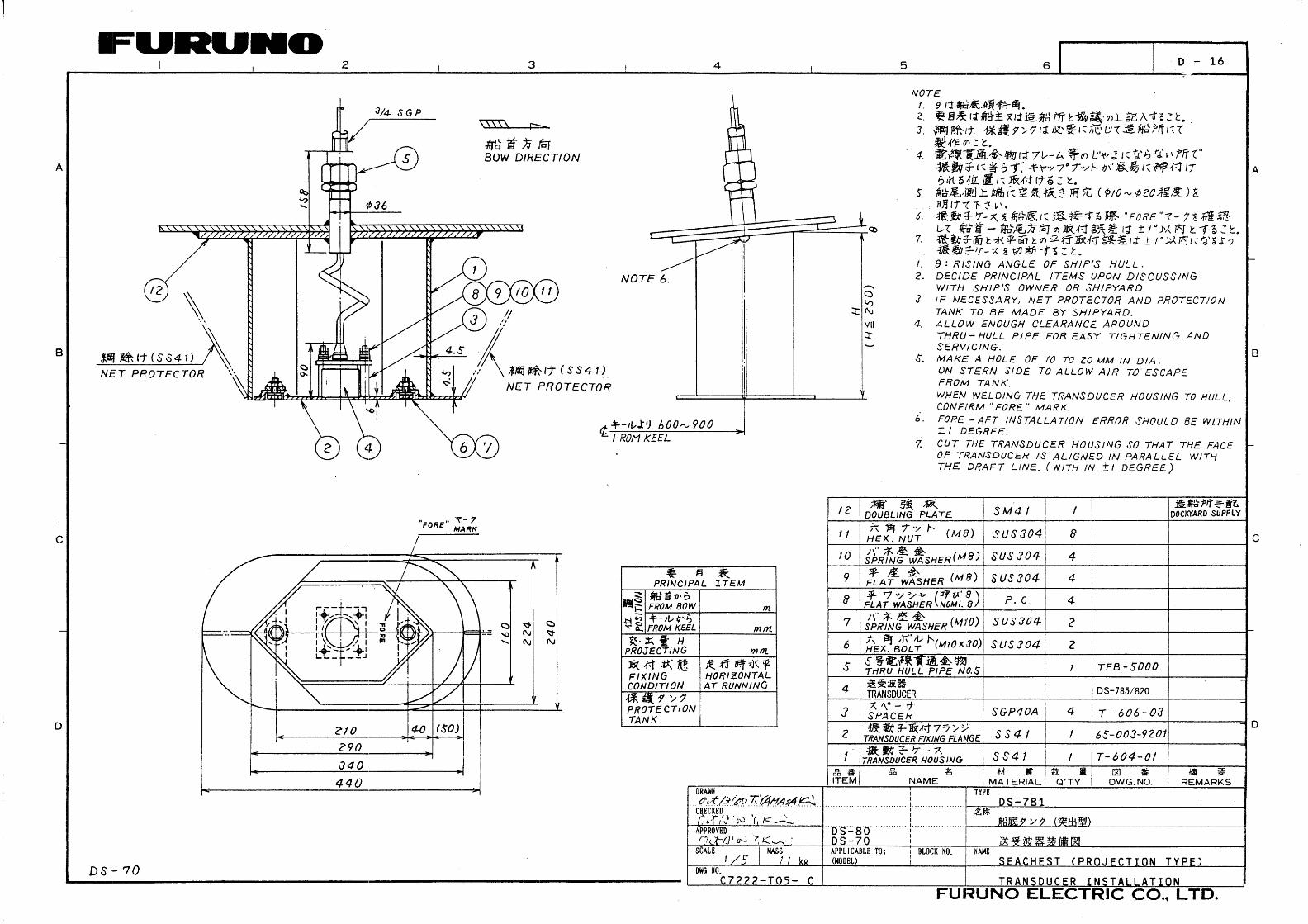
Mounting of Projection Type Seachest DS-781 (ref. Dwg. C72222-T05)
1. Weld doubling plate (supplied by shipyard) to hull plate.
2. Remove the M10 bolts, and take out transducer fixing flange (2) (including transducer) from
transducer housing (1).
3. Determine the projection distance, and cut transducer housing (1). The horizontal error
should be within 1°.
4. Before beginning this step, remove the rubber gasket inside the thru-hull pipe to prevent it
from melting. After cutting a hole through the hull plate for the thru-hull pipe (φ36), weld the
thru-hull pipe to the hull plate.
5. Weld transducer housing (1) to doubling plate. Direction error from fore-aft line should be
within 1°. At stern side of transducer housing, make air exhaust holes (φ 10-20).
6. Through the thru-hull pipe, pull up the transducer cable into the ship. Be careful not to jam
the cable between the flange and housing. Next, using the two M10X30 bolts (“Kinoruster”
applied) fasten the transducer fixing flange to the transducer housing.
Note: Never remove the four flat head screws.

9
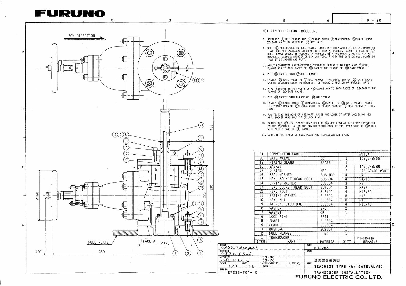
Mounting of Gate Valve Type Seachest DS-786 (ref. Dwg. E7222-T04)
1. Separate hull flange (2) and flange (4) (with transducer (1) and shaft (5) from gate valve (20)
by removing hex. nut.
2. Weld hull flange (2) to the hull plate. Confirm that the “FORE” and align marks on the side of
the hull flange face the fore-aft line of the ship within 1 degree.
3. Apply “Kinoruster (Anti-crevice corrosive sealant)” to face A of hull flang (2), both faces of
gasket (18) and flange of gate valve (20).
4. Put gasket (18) onto hull flange (2).
5. Mount gate valve (20), considering the direction of the handle (aft direction normally) so as
to allow enough space for operation.
6. Apply “Kinoruster” to face B of flange (4), both faces of gasket (18) and the flange of gate
valve (20).
7. Put gasket (18) onto the flange of gate valve (20).
8. Mount flange (4) (with transducer and shaft) to gate valve (20). Make sure the fore mark on
flange (4) and hull flange (2) are aligned.
9. Loosen the hex. socket head bolt, then check that shaft (5) moves upward and downward
smoothly by hand.
10. Lower shaft (5) completely and fasten hex. socket bolt (13).
(19)(7)(8)
(13)(14)(17)(17)
(21)
(6)
(10)(11)(4)(18)
(12)
(5)(20)
(9)(10)(11)(18)
(1) (3) (2)
(15)(16)

10
11. Confirm that the transducer is flush with the hull.
Note: Never weld the hull flange or transducer tank when the transducer is accommodated, nor weld near the transducer of other equipment.
When the transducer 1 is replaced, or separated from the shaft 5 re-assemble as follows;
FixingScrews
(4)Face CFace D
1. Remove sealant from face C and face D.2. Apply adhesive #1104 (Three Bond) to face D and four fixing screws.3. Re-assemble shaft and transducer.

11
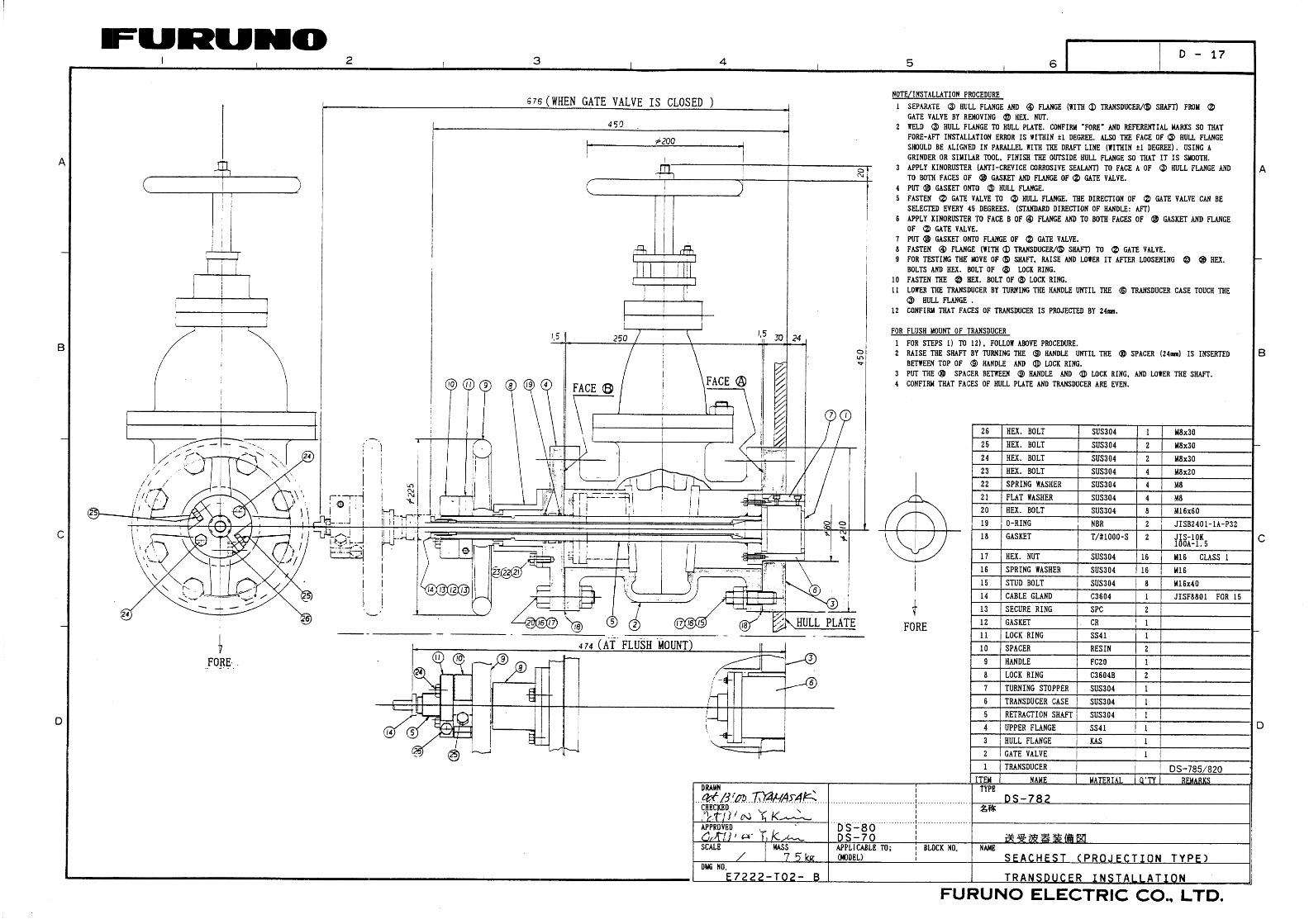
Gate valve, Projection Type Transducer DS-782 (ref. Dwg. E7222-T02)
DS-782
1. Separate hull flange (3) and flange (4) (with transducer (1) and shaft (5)) from gate valve (2) by removing hex. Nut (17).
2. Weld hull flange (3) to the hull plate. Confirm that the �FORE� and align marks on the side of the hull flange face the fore-aft line of the ship within 1 degree. The hull flange should also be horizontal within 1 degree at ship�s normal trim. Finish the outside hull plate flat with a grinder.
3. Apply �Kinoruster (Anti-crevice corrosive sealant)� to face A of hull flange ③, both faces of gasket (18) and flange of gate valve (2).
4. Put gasket (18) onto hull flange (13).
5. Mount gate valve (2), considering the direction of the handle (aft direction normally or selectable every 45 degrees) so as to allow enough space for operation.
6. Apply �Kinoruster� to face B of flange (4), both faces of gasket (18) and the flange of gate valve (2).
7. Put gasket (18) onto the flange of gate valve (2).
8. Mount flange (4) (with transducer and shaft) to gate valve.
9. Loosen the hex. socket head bolts (23)and (26), then check that shaft (5) moves upward and downward smoothly by hand.

12
10. Lower shaft (5) completely and fasten hex. socket bolt (23) and (26)
11. Lower the transducer by turning the handle until the transducer case (6) touches the hull flange (3).
12. Confirm that the hull plate projects by 24 mm.
Note: Never weld the hull flange or transducer tank when the transducer is being fitted, nor weld near the transducer of other equipment.
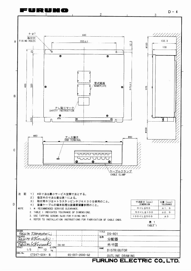
1.5 Distribution Box The distribution box can be mounted on the deck or on a bulkhead. Consider the following points when selecting a mounting location.
• Select a location which is both well ventilated and low in humidity to keep the unit cool.
• The unit weighs 12 kg. For bulkhead mounting, be sure the mounting location is strong enough to support the weight under the continued vibration normally encountered on the vessel.
• A magnetic compass will be affected if the distribution box is too close. Observe the compass safe distances to prevent disturbance to the magnetic compass.
Fasten the distribution box with four tapping screws (6X30, supplied). Refer to the outline drawing at the end of this manual for mounting dimensions.
For bulkhead mounting;
1. Tighten lower tapping screws so there is 5 mm clearance between bottom of screw head and bulkhead.
2. Screw slots of the unit with the tapping screws tightened at step 1.
3. Fasten the unit with upper tapping screws.

13
1.6 Terminal box (option) The terminal box forms a joint among the display unit, digital indicator, distance indicator and distribution box. Two digital indicators/distance indicators may be connected by installing an additional terminal box as follows.
• A magnetic compass will be affected if the terminal box is too close. Observe the compass safe distances to prevent disturbance to the magnetic compass.
Distribution box
Digital indicator/Distance indicator
(option)
Terminal box(option)
Terminal box(option)
Digital indicator/Distance indicator
(option)
Wiring with terminal box
Tighten four tapping screws (5X25) so there is 5 mm clearance between bottom of screw head and bulkhead, and screw slots of the unit with the tapping screws tightened.
1.7 Digital Indicator, Distance Indicator (option) The digital indicator and distance indicator use the same housing as the display unit.
Refer to the section 1.2 Display Unit for mounting instructions.

14
1.8 Junction Box (option)
1.8.1 Mounting considerations The junction box forms a joint between the distribution box and the transceiver unit, and it is designed to be mounted on a bulkhead. Install it referring to the guidelines below.
• Keep the junction box away from noise-emitting electrical machinery, for example, electric generator, radio transmitter, TV, etc.
• Although the box is splashproof, do not install it in places of high humidity.
• Avoid installing the box where temperature varies greatly, since moisture may penetrate the box.
• The box is generally installed above the draft line of the ship and the transducer cable is run inside steel conduit. This permits replacement of the transducer without dry docking. Even if the junction box is installed below the draft line, the conduit is necessary to minimize picking up of noise. If use of conduit is not possible, install the box as near to the transducer as possible.
Procedure
Open the box cover, and fix the unit to a bulkhead, referring to the outline drawing at the back of this manual.
15
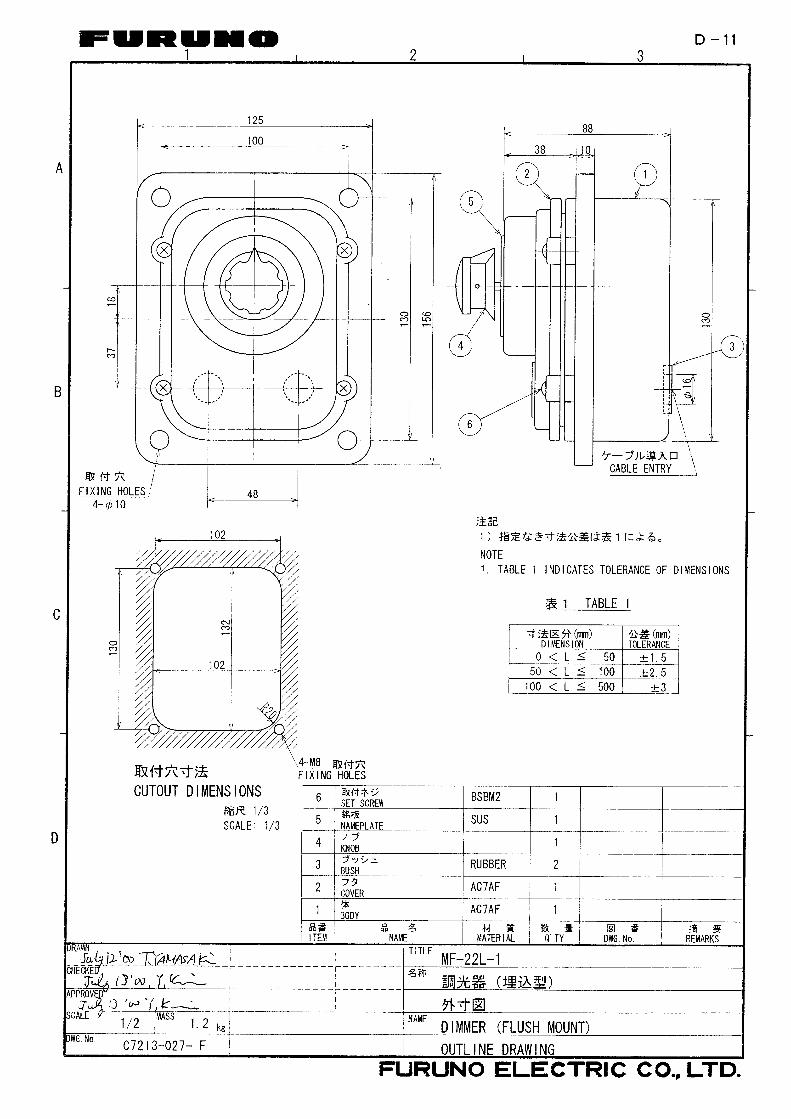
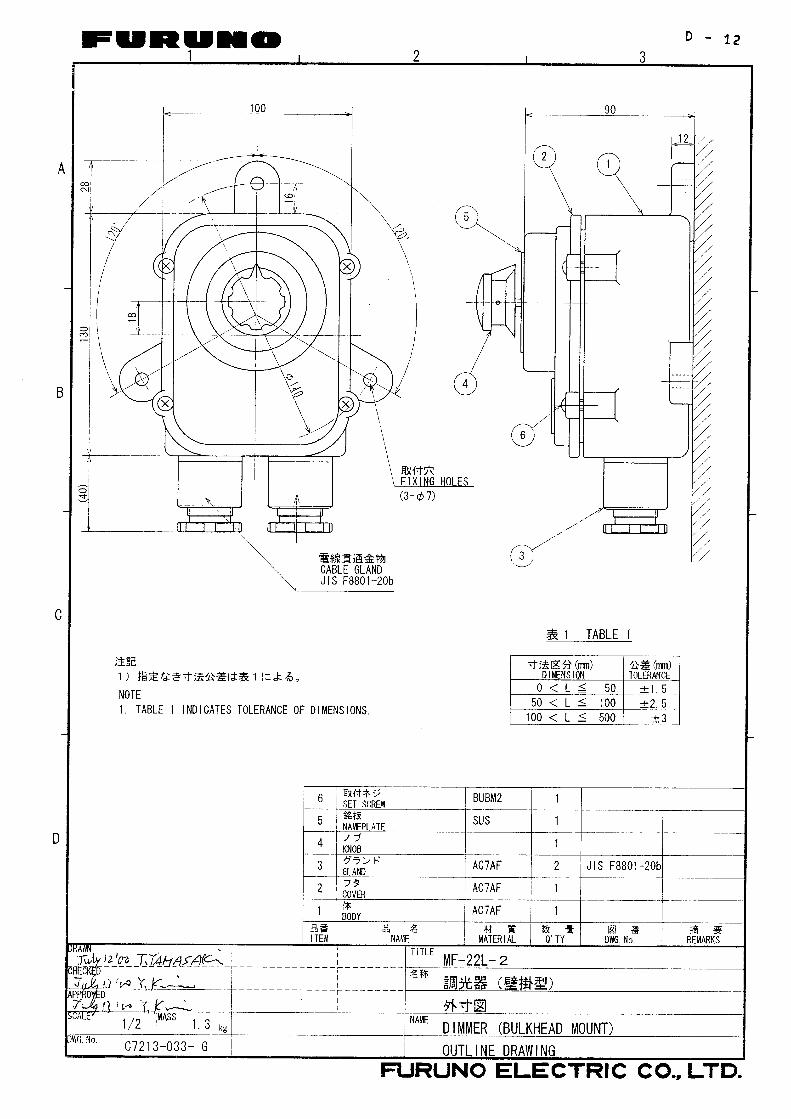
1.9 Dimmer (option) The optional dimmer, which is designed to comply with the Japan Industrial Standards (JIS F8852), is used for externally controlling the illumination of the display of the digital/analog displays. When a dimmer is supplied locally, refer to the interconnection diagram at the back of this manual for the values of the resistors since they are different depending on the display (digital or analog) and power supply (115 V or 230 VAC).
To use this equipment for display unit/digital indicator/distance indicator, set the dimmer setting on the unit menu. For detail, see �3.2 Setting of Unit Menu.
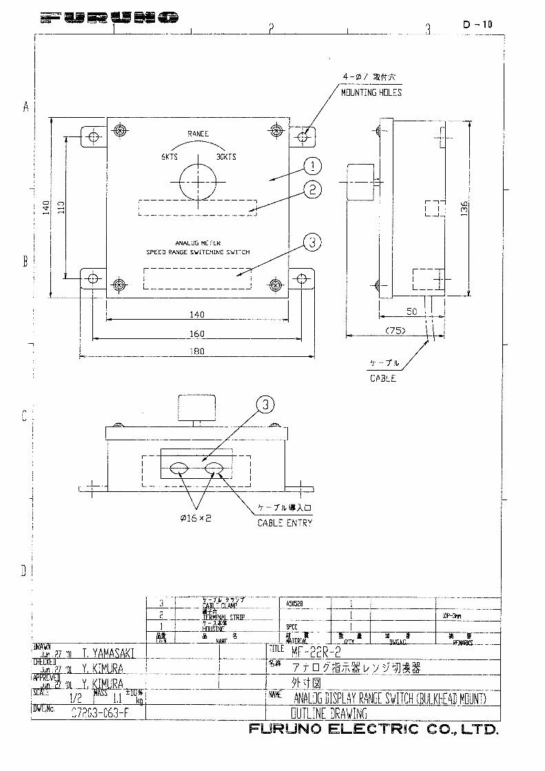
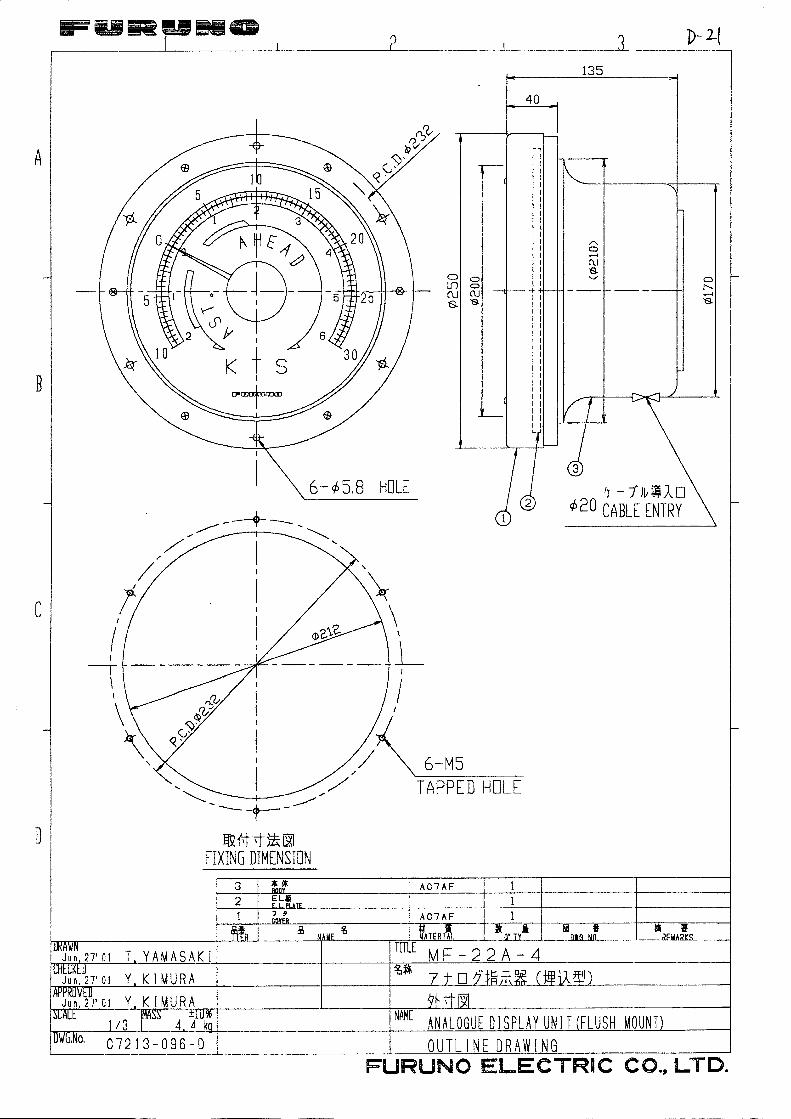
1.10 Range Switch Box, Analog Display Unit (option) The range switch box selects the range to display on the analog display unit (option), and the range scales are �2 to +6 knots and �10 to +30 knots.
These units are available in both bulkhead and flush mount versions. See the optional equipment list at the beginning of this manual and the outline drawing at the back of this manual.
When selecting a mounting location for these units keep the following in mind.
• The temperature and humidity of the mounting location should be moderate and stable.
• The mounting location should be well ventilated.
• Mount the unit where shock and vibration are minimal.
• Keep the analog display unit away from strong magnetic field-generating equipment such as transformer and power generator.
16
2 WIRING
2.1 Precautions for Cable Installation
Cable between transducer unit and transceiver unit This cable carries very weak signals with amplitude of less than 0.1 µV which are easily interfered by noise. Ensure the ground wiring.
Cable between transceiver unit and distribution box These cables carry echo signals with amplitudes of greater than 0.1 mV which can be interfered by noise from high tension power cables.
• Cable carrying more than few kilowatts power to fluctuating loads.
• Cable carrying switching waves generated by thyristor, etc.
• Transmission antenna cable of radio equipment.
Other cables of DS-80 Observe the following guidelines to prevent noise, interference problem.
• When the cables run in parallel with power cables, separate them 400 mm at minimum.
17
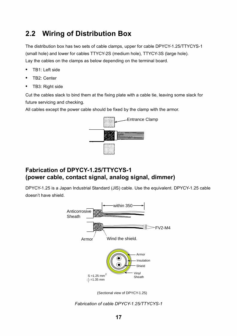
2.2 Wiring of Distribution Box The distribution box has two sets of cable clamps, upper for cable DPYCY-1.25/TTYCYS-1 (small hole) and lower for cables TTYCY-2S (medium hole), TTYCY-3S (large hole). Lay the cables on the clamps as below depending on the terminal board.
• TB1: Left side
• TB2: Center
• TB3: Right side
Cut the cables slack to bind them at the fixing plate with a cable tie, leaving some slack for future servicing and checking. All cables except the power cable should be fixed by the clamp with the armor.
Entrance Clamp
Fabrication of DPYCY-1.25/TTYCYS-1 (power cable, contact signal, analog signal, dimmer) DPYCY-1.25 is a Japan Industrial Standard (JIS) cable. Use the equivalent. DPYCY-1.25 cable doesn�t have shield.
FV2-M4
Armor
within 350AnticorrosiveSheath
Wind the shield.
VinylSheath
Armor
(Sectional view of DPYCY-1.25)
S =1.25 mm =1.35 mm
2
Shield
Insulation
Fabrication of cable DPYCY-1.25/TTYCYS-1

18
Fabrication of TTYCY-2S (display unit/digital indicator/distance indicator via terminal box, range switch box) TTYCY is a Japan Industrial Standard (JIS) cable. Use the equivalent.
350 mm approximately
15
Crimp-on LugFV2-M4
Remove the shield betweenthe fixing plate and terminal board.
Anticorrosivesheath
Anticorrosive sheath
Armor
(Sectional view)
S =1.25 mm =1.35 mm
2
Vinyl sheathConductor
Shield
Fabrication of cable TTYCY-2S

19
Fabrication of TTYCY-3S (transducer unit) TTYCY-3S is a Japan Industrial Standard (JIS) cable. Use the equivalent.
350 mm approximately
1515
20
Crimp-on LugFV2-M4
Remove the shield betweenthe fixing plate and terminal board.
Anticorrosive sheath
Armor
(Sectional view)
S =1.25 mm =1.35 mm
2
Vinyl sheathConductor
Shield
Fabrication of cable TTYCY-3S

20
Cable Fixing Plate(Fasten the shield of cable.)Terminal Board
1234567891011121314151617181920
1234567891011121314151617181920
1234567891011121314151617181920
Display Unit
Transceiver unit
Analogindicator
Rangeswitch
Analogvoltage signal
Digitaldisplay
Contactsignal
IEC61162OUTIEC61162OUTIEC61162INPower ON switch
TB1 TB2 TB3
Upper
Lower
Upper
Lower
Upper
Lower
Digitaldisplay
Analogindicator
Rangeswitch
Analogcurrent signal
ContactsignalContactsignal
Distribution Box, inside view and terminal boxes
21
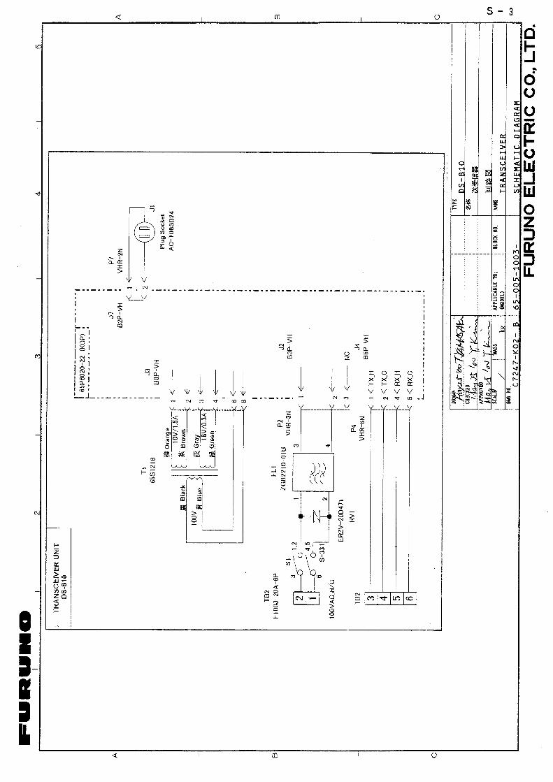
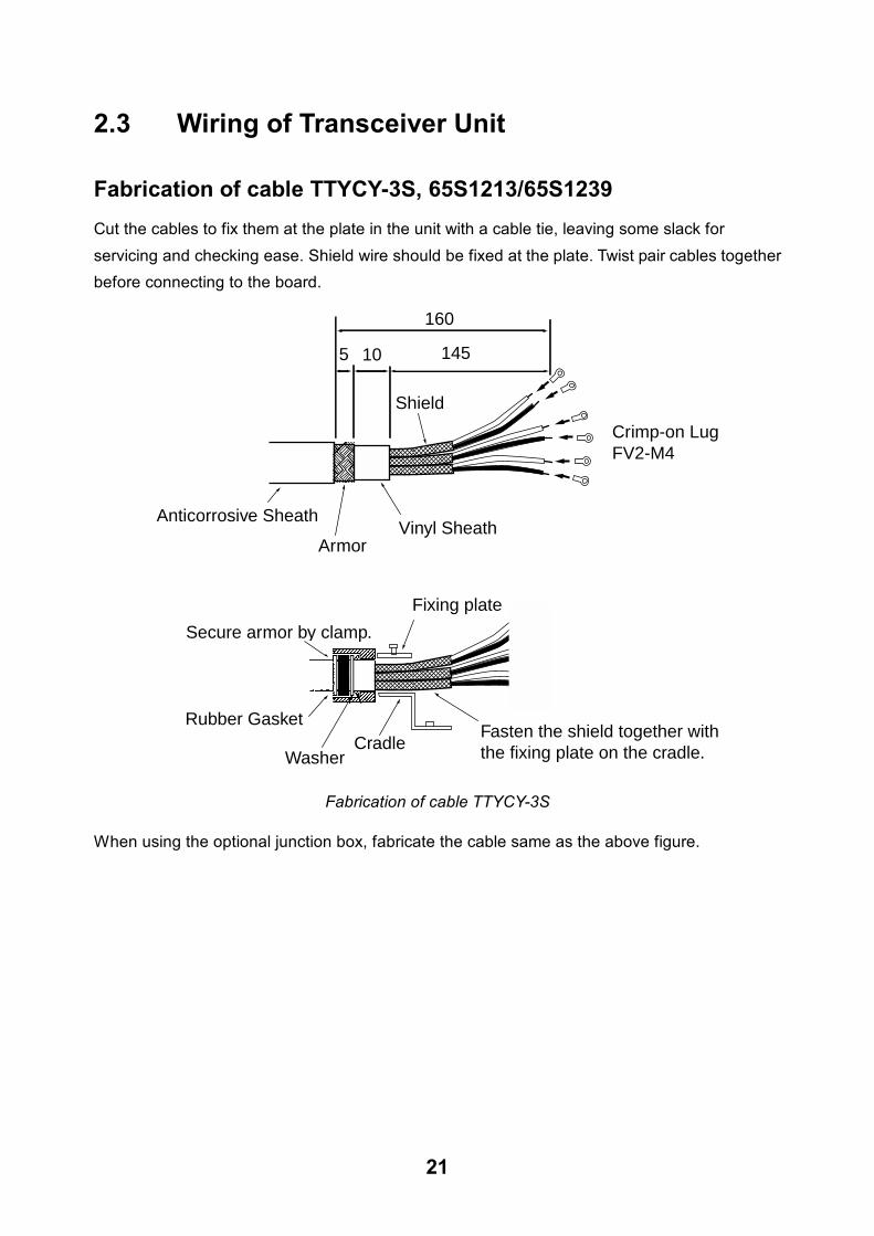
2.3 Wiring of Transceiver Unit
Fabrication of cable TTYCY-3S, 65S1213/65S1239 Cut the cables to fix them at the plate in the unit with a cable tie, leaving some slack for servicing and checking ease. Shield wire should be fixed at the plate. Twist pair cables together before connecting to the board.
5 10
Shield
Crimp-on LugFV2-M4
Secure armor by clamp.
Rubber Gasket
Washer
145
160
Cradle
Fixing plate
Fasten the shield together withthe fixing plate on the cradle.
Anticorrosive SheathVinyl Sheath
Armor
Fabrication of cable TTYCY-3S
When using the optional junction box, fabricate the cable same as the above figure.

22
Terminal board
Cable gland(for 65S1213/65S1239)
Fixing plateLay the shield of cable, and then tighten.
Transceiver unit, inside view 1
Terminal board
Cable gland(for TTYCY-3S)
Fixing plateLay the shield of cable,and then tighten.
Transceiver unit, inside view 2
23
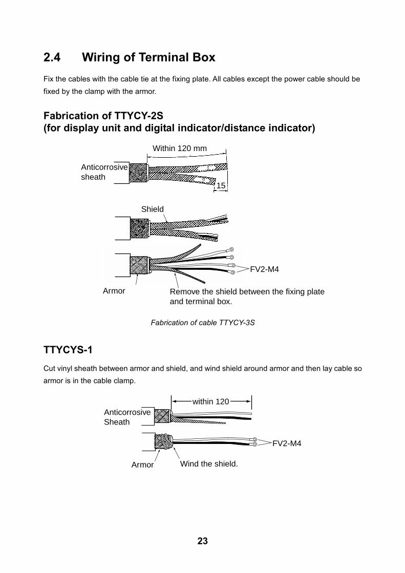
2.4 Wiring of Terminal Box Fix the cables with the cable tie at the fixing plate. All cables except the power cable should be fixed by the clamp with the armor.
Fabrication of TTYCY-2S (for display unit and digital indicator/distance indicator)
Within 120 mm
20
15
Anticorrosive sheath
1
2
Remove the shield between the fixing plateand terminal box.
Armor
Shield
FV2-M4
Fabrication of cable TTYCY-3S
TTYCYS-1 Cut vinyl sheath between armor and shield, and wind shield around armor and then lay cable so armor is in the cable clamp.
FV2-M4
Armor
within 120AnticorrosiveSheath
Wind the shield.

24
20S0251 (for display unit, digital indicator/distance indicator) • Locate the fuse of the cable inside the terminal box.
• Tape the drain wire, and fix the earth terminal in the terminal box.
• Outer sheath should be fixed in the cable clamp.
65S1231 (for display unit, digital indicator/distance indicator) Strip the outer sheath by 120 mm, and fasten it by the clamp. Attach the climp-on lug FV0.5-4 to each core.
2.5 Display Unit
(Digital Indicator, Distance Indicator) Use the cable assemblies MJ-A7SPF0009-020 and MJ-A6SPF0013-020 (supplied).
Connect the cable at the rear of the display unit, and fabricate the other end of the cable for connection to the terminal box. Refer to the interconnection diagram at the end of this manual.
2.6 Dimmer, Analog Display Unit, Range Switch
Box See the schematic diagram at the back of this manual.
Range switch box
TTYCY-2S DPYCY-1.25 DPYCY-1.25
DP
YC
Y-1.
25
Dimmer
Analog display
25
2.7 Grounding
This equipment uses pulse signals which may cause interference to other electronic equipment.
It is strongly recommended to ground all cables referring to the guidelines below.
• Separate all units as far as possible from radio equipment.
• Do not run interconnection cables close to or near radio equipment or its cables.
• Run the cables in the shortest path practical.
• Ground all units with a copper strap or earth wire.
• To joint copper straps, use solder cream for perfect contact.
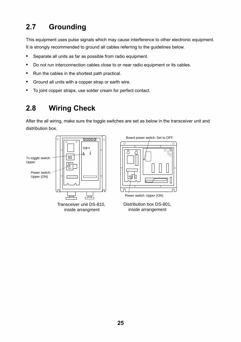
2.8 Wiring Check
After the all wiring, make sure the toggle switches are set as below in the transceiver unit and
distribution box.
Power switch: Upper (ON)
S1
Tx toggle switch: Upper
Transceiver unit DS-810, inside arrangment
ON
OFF
Power switch: Upper (ON)
Board power switch: Set to OFF.
Distribution box DS-801,inside arrangement
ON
OFF
26
3 SYSTEM SETTINGS
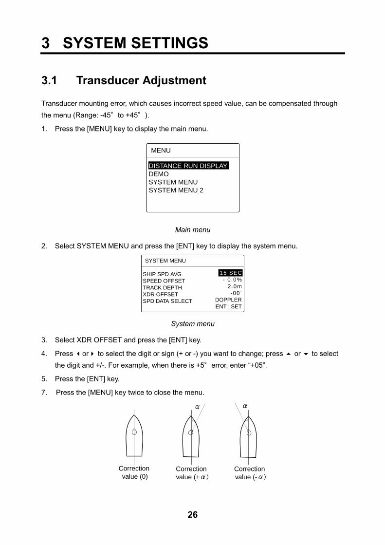
3.1 Transducer Adjustment
Transducer mounting error, which causes incorrect speed value, can be compensated through
the menu (Range: -45°to +45°).
1. Press the [MENU] key to display the main menu.
DISTANCE RUN DISPLAYDEMO SYSTEM MENUSYSTEM MENU 2
MENU
Main menu
2. Select SYSTEM MENU and press the [ENT] key to display the system menu.
SYSTEM MENU
SHIP SPD AVGSPEED OFFSETTRACK DEPTHXDR OFFSETSPD DATA SELECT
15 SEC- 0.0%
2.0m-00
DOPPLERENT : SET
System menu
3. Select XDR OFFSET and press the [ENT] key.
4. Press !or" to select the digit or sign (+ or -) you want to change; press # or $ to select
the digit and +/-. For example, when there is +5°error, enter “+05”.
5. Press the [ENT] key.
7. Press the [MENU] key twice to close the menu.
Correction value (0)
Correction value (+
Correction value (-

27
3.2 Setting of System Menu 2 System menu 2 provides for selection of display language and dimmer control, as well as a diagnostic facility.
Dimmer setting Select the adjustment method of panel dimmer, internal or external.
1. Press the [MENU] key to display the main menu.
2. Select SYSTEM MENU 2 and then press the [ENT] key.
SYSTEM MENU 2
INTERNALENGLISH
ENT : SET
TESTDIMMER /LANG.
Unit menu
3. Select DIMMER and press the [ENT] key to display the dimmer pop-up window.
INTERNALEXTERNAL
Dimmer pop-up dialog
4. Select INTERNAL or EXTERNAL with # or $ key. INTERNAL: Without external dimmer control.
EXTERNAL: With an external dimmer.
5. Press the [ENT] key.
6. Press the [MENU] key twice to close the menu.
28
Setting of language
The display language can be selected for English or Japanese.
1. Press the [MENU] key to display the main menu.
2. Select SYSTEM MENU 2 and press the [ENT] key to display the system menu 2.
3. Select LANG. And press the [ENT] key to display the language pop-up menu.
E N G L I S H
Language pop-up window
4. Select ENGLISH or JAPANESE with # or $ key.
5. Press the [ENT] key.
6. Press the [MENU] key twice to close the menu.
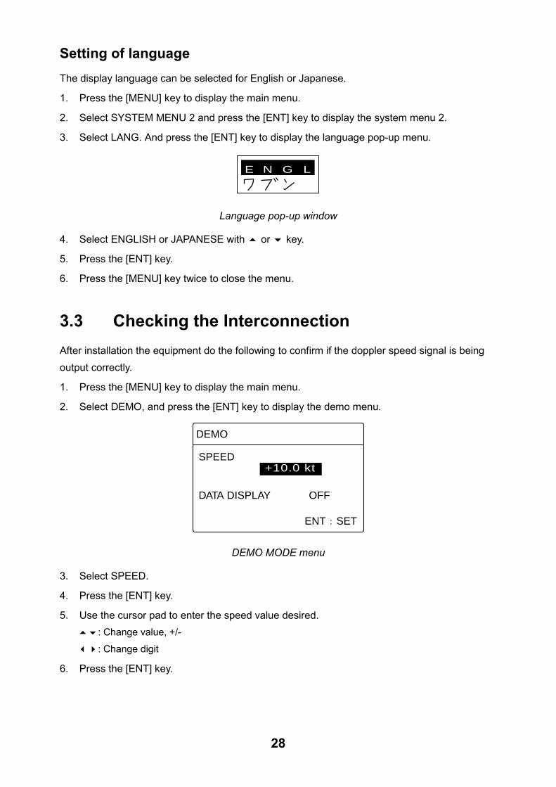
3.3 Checking the Interconnection
After installation the equipment do the following to confirm if the doppler speed signal is being
output correctly.
1. Press the [MENU] key to display the main menu.
2. Select DEMO, and press the [ENT] key to display the demo menu.
DEMO
+10.0 ktSPEED
DATA DISPLAY OFF
ENT SET
DEMO MODE menu
3. Select SPEED.
4. Press the [ENT] key.
5. Use the cursor pad to enter the speed value desired.
#$: Change value, +/-
!": Change digit
6. Press the [ENT] key.

29
7. Select DATA OUTPUT and press the [ENT] key.
8. Press # to select ON and press the [ENT] key.
9. Press the [DISP] key.
10. Confirm the value displayed is the same as it entered at step 5. Confirm the same as speed is shown on external equipment (radar, GPS, etc.).
11. Select OFF at DATA OUTPUT, and press the [ENTER] key.
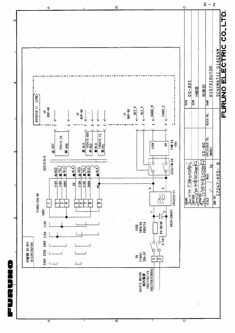
3.4 Setting of Maximum Speed Range Change the maximum range of the connected analog display by setting ofDIP switch S2 in the distribution box.
Maximum speed 20 kt 30 kt 40 kt S2 #1: ON
Others: OFF All: OFF #2: ON
Others: OFF
JPW Board(65P6010)
Distribution box DS-801,inside view
S2(Default setting: all OFF)
Distribution box, cover removed
3.5 Ship's Speed Adjustments Adjusts the speed error using the test sheet on page AP-3 recorded.
1. Press the [MENU] key.
2. Select SYSTEM MENU, and press the [ENT] key.
3. Select SPEED OFFSET, and press the [ENT] key.
4. Use the cursor pad to enter the digit.
5. Press the [ENT] key.
6. Press the [MENU] key.
For detail, see page AP-1.
30
3.6 Setting for Analog Display When the analog indicator is connected, synchronize the speed displays of DS-80 display unit and analog display as follows.
Analog interface
Current output: 4 to 20 mA (-10 to 30 kt)
Voltage output: -3.3 to 10VDC (-10 to 30 kt)
Connected to TB2 ANA1 (analog 1)
1. Set at 0 knot on the DEMO display, and then adjust R29 in the distribution box so as that the analog display shows 0 knots.
2. Set at 30 knots on the DEMO display, and then adjust R40 in the distribution box so as that the analog display shows 30 knots.
Connected to TB2 ANA2 (analog 2)
1. Set at 0 knots on the DEMO display, and then adjust R27 in the distribution box so as that the analog display shows 0 knots.
2. Set at 30 knots on the DEMO display, and then adjust R36 in the distribution box so as that the analog display shows 30 knots.
Connected to TB2 ANAV (analog voltage signal)
1. Set at 0 knots on the DEMO display, and then adjust R100 in the distribution box so as that the analog display shows 0 knots.
2. Set at 30 knots on the DEMO display, and then adjust R145 in the distribution box so as that the analog display shows 30 knots.
Connected to TB2 ANAC (analog current signal)
1. Set at -10 knots on the DEMO display, and then adjust R87 in the distribution box so as that the current is 4 mA.
2. Set at +30 knots on the DEMO display, and then adjust R96 in the distribution box so as that the current is 20 mA.

31
Power switch: Upper
Set to OFF.
Distribution box DS-801
ON
OFF
R100R145R96
R87R40R29
R36
R27
3.7 DIP Switch Settings JPW Board (65P6010) S4-#6
The default setting (OFF) outputs only sentences VBW and VLW of all NMEA sentences input.
DIP switch S4-#6 setting OFF ON Output NMEA sentences VBW, VLW All NMEA sentences
S4-#8
Select whether to output or don't output the distance run pulse if an error occurs, when DOPPLER is selected at SPD DATA in the SYSTEM MENU.
DIP switch S4-#8 OFF ON Distance run pulse Output stopped Output not stopped
Note: S4 #1-#5, #7, S2 #3, #4 should remain OFF, the default setting.
JPW Board (65P6010)
S4
Distribution box, cover removed
32
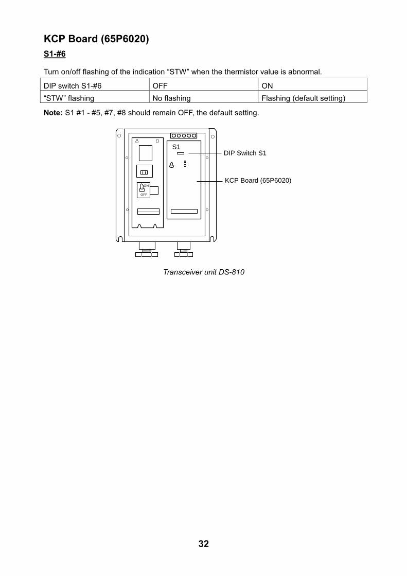
KCP Board (65P6020) S1-#6
Turn on/off flashing of the indication �STW� when the thermistor value is abnormal.
DIP switch S1-#6 OFF ON �STW� flashing No flashing Flashing (default setting)
Note: S1 #1 - #5, #7, #8 should remain OFF, the default setting.
S1
ON
OFF
KCP Board (65P6020)
DIP Switch S1
Transceiver unit DS-810
33
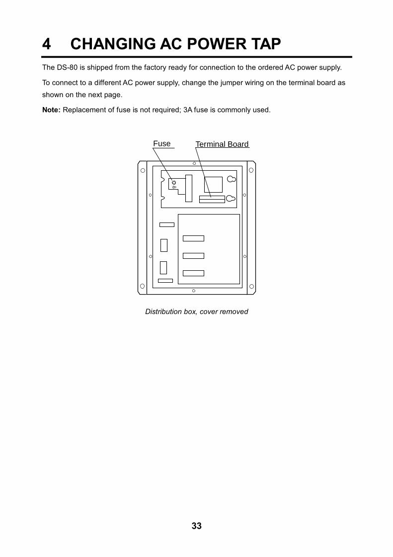
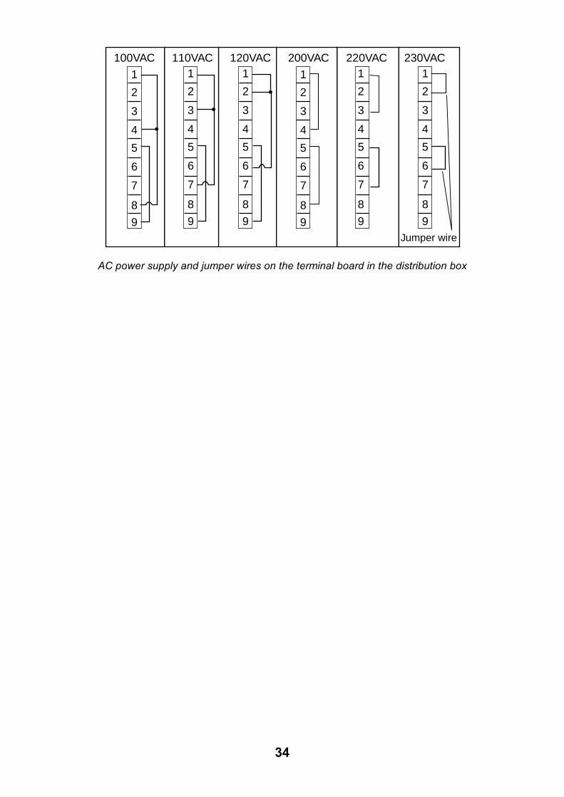
4 CHANGING AC POWER TAP The DS-80 is shipped from the factory ready for connection to the ordered AC power supply.
To connect to a different AC power supply, change the jumper wiring on the terminal board as shown on the next page.
Note: Replacement of fuse is not required; 3A fuse is commonly used.
Terminal BoardFuse
Distribution box, cover removed
34
100VAC 110VAC 120VAC 200VAC 220VAC 230VAC
1
2
3
4
5
6
7
8
9
1
2
3
4
5
6
7
8
9
1
2
3
4
5
6
7
8
9
1
2
3
4
5
6
7
8
9
1
2
3
4
5
6
7
8
9
1
2
3
4
5
6
7
8
9Jumper wire
AC power supply and jumper wires on the terminal board in the distribution box

AP-1
CALIBRATION
Milepost run
It is common practice to check a new ship’s performance at an official trial run. Take this
opportunity to calibrate the DS-80.
In practice, the ship speed is evaluated as follows.
1. Calculation with transit posts
Steer the ship at a steady speed on the test course, e.g. A →B in the illustration. Speed
is obtained from the following equations. Note that Sg1 and Sg2 are both speeds over
the ground (SOG); however the DS-80 provides the speed through the water. To find the
speed through the water, a return trip is necessary.
P1
P1'
P2
P2'
A B
Transit Posts Transit Posts
d
Sg1
Sg2
St
Sg1 = d/t1 X 3600 (kt)……..(1)
Sg2 = d/t2 X 3600 (kt)……..(2)
Sw + St = Sg1 (kt)…..(3)
Sw – St = Sg2 (kt)…..(4)
Adding (4) and (3), we get;
2Sw = Sg1 + Sg2 (kt)
Therefore, Sw = (Sg1 + Sg2)/2 (kt)….(5)
where,
d = distance run (nm),
AP-2
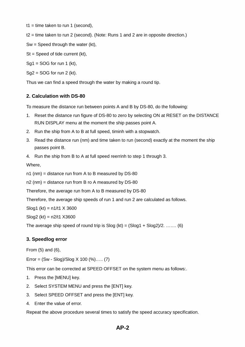
t1 = time taken to run 1 (second),
t2 = time taken to run 2 (second). (Note: Runs 1 and 2 are in opposite direction.)
Sw = Speed through the water (kt),
St = Speed of tide current (kt),
Sg1 = SOG for run 1 (kt),
Sg2 = SOG for run 2 (kt).
Thus we can find a speed through the water by making a round tip.
2. Calculation with DS-80
To measure the distance run between points A and B by DS-80, do the following:
1. Reset the distance run figure of DS-80 to zero by selecting ON at RESET on the DISTANCE
RUN DISPLAY menu at the moment the ship passes point A.
2. Run the ship from A to B at full speed, timinh with a stopwatch.
3. Read the distance run (nm) and time taken to run (second) exactly at the moment the ship
passes point B.
4. Run the ship from B to A at full speed reerrinh to step 1 through 3.
Where,
n1 (nm) = distance run from A to B measured by DS-80
n2 (nm) = distance run from B ro A measured by DS-80
Therefore, the average run from A to B measured by DS-80
Therefore, the average ship speeds of run 1 and run 2 are calculated as follows.
Slog1 (kt) = n1/t1 X 3600
Slog2 (kt) = n2/t1 X3600
The average ship speed of round trip is Slog (kt) = (Slog1 + Slog2)/2. ……. (6)
3. Speedlog error
From (5) and (6),
Error = (Sw - Slog)/Slog X 100 (%)….. (7)
This error can be corrected at SPEED OFFSET on the system menu as follows:.
1. Press the [MENU] key.
2. Select SYSTEM MENU and press the [ENT] key.
3. Select SPEED OFFSET and press the [ENT] key.
4. Enter the value of error.
Repeat the above procedure several times to satisfy the speed accuracy specification.

AP-3
CA
LIB
RAT
ION
SH
EE
T F
OR
DS
-80
DO
PP
LER
SP
EE
D L
OG
DAT
E:
TE
ST
SIT
E
S
HIP
'S L
EN
GT
H
(M
)
DR
AF
T F
ore
Aft
Mea
n (
m)
SH
IP'S
NA
ME
Ser
. No.
D
OC
KYA
RD
T
RIM
(m
)
.
DS
-80
Loca
tion
of T
rans
duce
r
(m)
from
bow
or
fram
e N
o.
SEA
STA
TE

This page is intentionally left blank.

NAME
OUTLINE
Q'TY
DESCRIPTION/CODE №
PACKING LIST
PACKING LIST
PACKING LIST
PACKING LIST
65AD-X-9851-3
DS-800
DS-800
DS-800
DS-800
1/1
NAME
OUTLINE
Q'TY
DESCRIPTION/CODE №
ユニット
ユニット
ユニット
ユニット
UNIT
UNIT
UNIT
UNIT
主指示器
MAIN DISPLAY
DS-800
000-029-012
1
**
付属品
付属品
付属品
付属品
ACCESSORIES
ACCESSORIES
ACCESSORIES
ACCESSORIES
FP65-00401
FP65-00401
FP65-00401
FP65-00401
六角ボルト スリ割り
HEX.BOLT(SLOTTED HEAD)
M6X12 SUS304
000-862-127
2
バネ座金
SPRING WASHER
M6 SUS304
000-864-260
2
化粧パネル
COSMETIC PANEL
20-016-1051-0
100-251-370
1
付属品
付属品
付属品
付属品
ACCESSORIES
ACCESSORIES
ACCESSORIES
ACCESSORIES
FP65-00402
FP65-00402
FP65-00402
FP65-00402
蝶ボルト
WING SCREW
M4X30 YBSC2 MBNI2
000-804-799
4
六角ボルト スリ割り
HEX.BOLT(SLOTTED HEAD)
M6X12 SUS304
000-862-127
2
蝶ナット
WING NUT
M4 YBSC2 MBNI2
000-863-306
4
フラッシュマウント
FIXING PLATE FOR FLUSH
MOUNT
20-007-2401-0
100-183-190
2
バネ座金
SPRING WASHER
M6 SUS304
000-864-260
2
付属品
付属品
付属品
付属品
ACCESSORIES
ACCESSORIES
ACCESSORIES
ACCESSORIES
FP65-00403
FP65-00403
FP65-00403
FP65-00403
+トラスタッピンネジ
TAPPING SCREW
5X20 SUS304 1種 クロ
000-802-840
4
工事材料
工事材料
工事材料
工事材料
INSTALLATION MATERIALS
INSTALLATION MATERIALS
INSTALLATION MATERIALS
INSTALLATION MATERIALS
CP65-00801
CP65-00801
CP65-00801
CP65-00801
圧着端子
CRIMP-ON LUG
FV0.5-4 キ(YEL)
000-107-268
20
その他工材
その他工材
その他工材
その他工材
OTHER INSTALLATION MATERIALS
OTHER INSTALLATION MATERIALS
OTHER INSTALLATION MATERIALS
OTHER INSTALLATION MATERIALS
ケーブル組品MJ
CABLE ASSY.
MJ-A7SPF0009-020
000-145-612
1
ケーブル組品MJ
CABLE ASSY.
MJ-A6SPF0013-020
000-142-658
1
注記
) 1
.コ-ド番
号末
尾の
[**]は
、選択
部品
の代
表コ-ド番号
を表
します。
CO
DE N
UM
BER
EN
DED
BY "
**" IN
DIC
ATES T
HE N
UM
BER
OF T
YP
ICA
L M
ATER
IAL.
(略図の寸法は、参考値です。 DIMENSIONS IN DRAWING FOR REFERENCE ONLY.)
(略図の寸法は、参考値です。 DIMENSIONS IN DRAWING FOR REFERENCE ONLY.)
(略図の寸法は、参考値です。 DIMENSIONS IN DRAWING FOR REFERENCE ONLY.)
(略図の寸法は、参考値です。 DIMENSIONS IN DRAWING FOR REFERENCE ONLY.)
NAME
OUTLINE
Q'TY
DESCRIPTION/CODE №
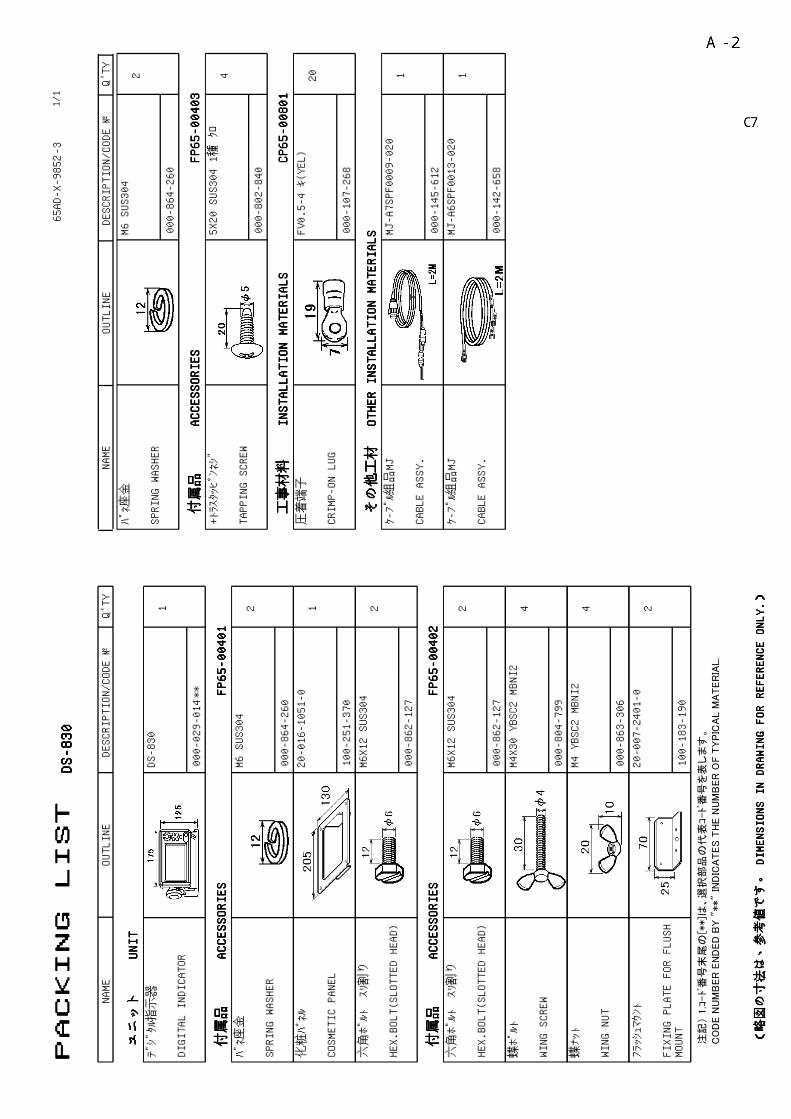
PACKING LIST
PACKING LIST
PACKING LIST
PACKING LIST
65AD-X-9852-3
DS-830
DS-830
DS-830
DS-830
1/1
NAME
OUTLINE
Q'TY
DESCRIPTION/CODE №
ユニット
ユニット
ユニット
ユニット
UNIT
UNIT
UNIT
UNIT
デジタル指示器
DIGITAL INDICATOR
DS-830
000-029-014
1
**
付属品
付属品
付属品
付属品
ACCESSORIES
ACCESSORIES
ACCESSORIES
ACCESSORIES
FP65-00401
FP65-00401
FP65-00401
FP65-00401
バネ座金
SPRING WASHER
M6 SUS304
000-864-260
2
化粧パネル
COSMETIC PANEL
20-016-1051-0
100-251-370
1
六角ボルト スリ割り
HEX.BOLT(SLOTTED HEAD)
M6X12 SUS304
000-862-127
2
付属品
付属品
付属品
付属品
ACCESSORIES
ACCESSORIES
ACCESSORIES
ACCESSORIES
FP65-00402
FP65-00402
FP65-00402
FP65-00402
六角ボルト スリ割り
HEX.BOLT(SLOTTED HEAD)
M6X12 SUS304
000-862-127
2
蝶ボルト
WING SCREW
M4X30 YBSC2 MBNI2
000-804-799
4
蝶ナット
WING NUT
M4 YBSC2 MBNI2
000-863-306
4
フラッシュマウント
FIXING PLATE FOR FLUSH
MOUNT
20-007-2401-0
100-183-190
2
バネ座金
SPRING WASHER
M6 SUS304
000-864-260
2
付属品
付属品
付属品
付属品
ACCESSORIES
ACCESSORIES
ACCESSORIES
ACCESSORIES
FP65-00403
FP65-00403
FP65-00403
FP65-00403
+トラスタッピンネジ
TAPPING SCREW
5X20 SUS304 1種 クロ
000-802-840
4
工事材料
工事材料
工事材料
工事材料
INSTALLATION MATERIALS
INSTALLATION MATERIALS
INSTALLATION MATERIALS
INSTALLATION MATERIALS
CP65-00801
CP65-00801
CP65-00801
CP65-00801
圧着端子
CRIMP-ON LUG
FV0.5-4 キ(YEL)
000-107-268
20
その他工材
その他工材
その他工材
その他工材
OTHER INSTALLATION MATERIALS
OTHER INSTALLATION MATERIALS
OTHER INSTALLATION MATERIALS
OTHER INSTALLATION MATERIALS
ケーブル組品MJ
CABLE ASSY.
MJ-A7SPF0009-020
000-145-612
1
ケーブル組品MJ
CABLE ASSY.
MJ-A6SPF0013-020
000-142-658
1
注記
) 1
.コ-ド番
号末
尾の
[**]は
、選択
部品
の代
表コ-ド番号
を表
します。
CO
DE N
UM
BER
EN
DED
BY "
**" IN
DIC
ATES T
HE N
UM
BER
OF T
YP
ICA
L M
ATER
IAL.
(略図の寸法は、参考値です。 DIMENSIONS IN DRAWING FOR REFERENCE ONLY.)
(略図の寸法は、参考値です。 DIMENSIONS IN DRAWING FOR REFERENCE ONLY.)
(略図の寸法は、参考値です。 DIMENSIONS IN DRAWING FOR REFERENCE ONLY.)
(略図の寸法は、参考値です。 DIMENSIONS IN DRAWING FOR REFERENCE ONLY.)
NAME
OUTLINE
Q'TY
DESCRIPTION/CODE №
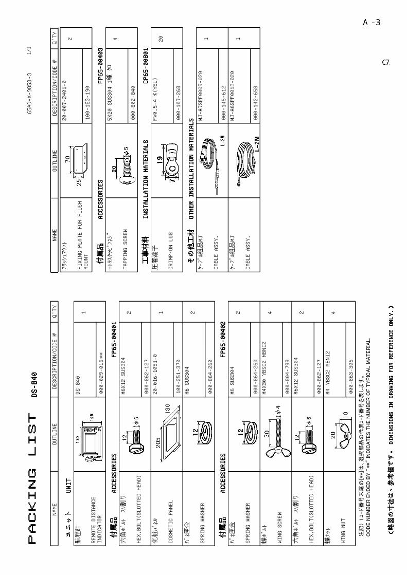
PACKING LIST
PACKING LIST
PACKING LIST
PACKING LIST
65AD-X-9853-3
DS-840
DS-840
DS-840
DS-840
1/1
NAME
OUTLINE
Q'TY
DESCRIPTION/CODE №
ユニット
ユニット
ユニット
ユニット
UNIT
UNIT
UNIT
UNIT
航程計
REMOTE DISTANCE
INDICATOR
DS-840
000-029-016
1
**
付属品
付属品
付属品
付属品
ACCESSORIES
ACCESSORIES
ACCESSORIES
ACCESSORIES
FP65-00401
FP65-00401
FP65-00401
FP65-00401
六角ボルト スリ割り
HEX.BOLT(SLOTTED HEAD)
M6X12 SUS304
000-862-127
2
化粧パネル
COSMETIC PANEL
20-016-1051-0
100-251-370
1
バネ座金
SPRING WASHER
M6 SUS304
000-864-260
2
付属品
付属品
付属品
付属品
ACCESSORIES
ACCESSORIES
ACCESSORIES
ACCESSORIES
FP65-00402
FP65-00402
FP65-00402
FP65-00402
バネ座金
SPRING WASHER
M6 SUS304
000-864-260
2
蝶ボルト
WING SCREW
M4X30 YBSC2 MBNI2
000-804-799
4
六角ボルト スリ割り
HEX.BOLT(SLOTTED HEAD)
M6X12 SUS304
000-862-127
2
蝶ナット
WING NUT
M4 YBSC2 MBNI2
000-863-306
4
フラッシュマウント
FIXING PLATE FOR FLUSH
MOUNT
20-007-2401-0
100-183-190
2
付属品
付属品
付属品
付属品
ACCESSORIES
ACCESSORIES
ACCESSORIES
ACCESSORIES
FP65-00403
FP65-00403
FP65-00403
FP65-00403
+トラスタッピンネジ
TAPPING SCREW
5X20 SUS304 1種 クロ
000-802-840
4
工事材料
工事材料
工事材料
工事材料
INSTALLATION MATERIALS
INSTALLATION MATERIALS
INSTALLATION MATERIALS
INSTALLATION MATERIALS
CP65-00801
CP65-00801
CP65-00801
CP65-00801
圧着端子
CRIMP-ON LUG
FV0.5-4 キ(YEL)
000-107-268
20
その他工材
その他工材
その他工材
その他工材
OTHER INSTALLATION MATERIALS
OTHER INSTALLATION MATERIALS
OTHER INSTALLATION MATERIALS
OTHER INSTALLATION MATERIALS
ケーブル組品MJ
CABLE ASSY.
MJ-A7SPF0009-020
000-145-612
1
ケーブル組品MJ
CABLE ASSY.
MJ-A6SPF0013-020
000-142-658
1
注記
) 1
.コ-ド番
号末
尾の
[**]は
、選択
部品
の代
表コ-ド番号
を表
します。
CO
DE N
UM
BER
EN
DED
BY "
**" IN
DIC
ATES T
HE N
UM
BER
OF T
YP
ICA
L M
ATER
IAL.
(略図の寸法は、参考値です。 DIMENSIONS IN DRAWING FOR REFERENCE ONLY.)
(略図の寸法は、参考値です。 DIMENSIONS IN DRAWING FOR REFERENCE ONLY.)
(略図の寸法は、参考値です。 DIMENSIONS IN DRAWING FOR REFERENCE ONLY.)
(略図の寸法は、参考値です。 DIMENSIONS IN DRAWING FOR REFERENCE ONLY.)
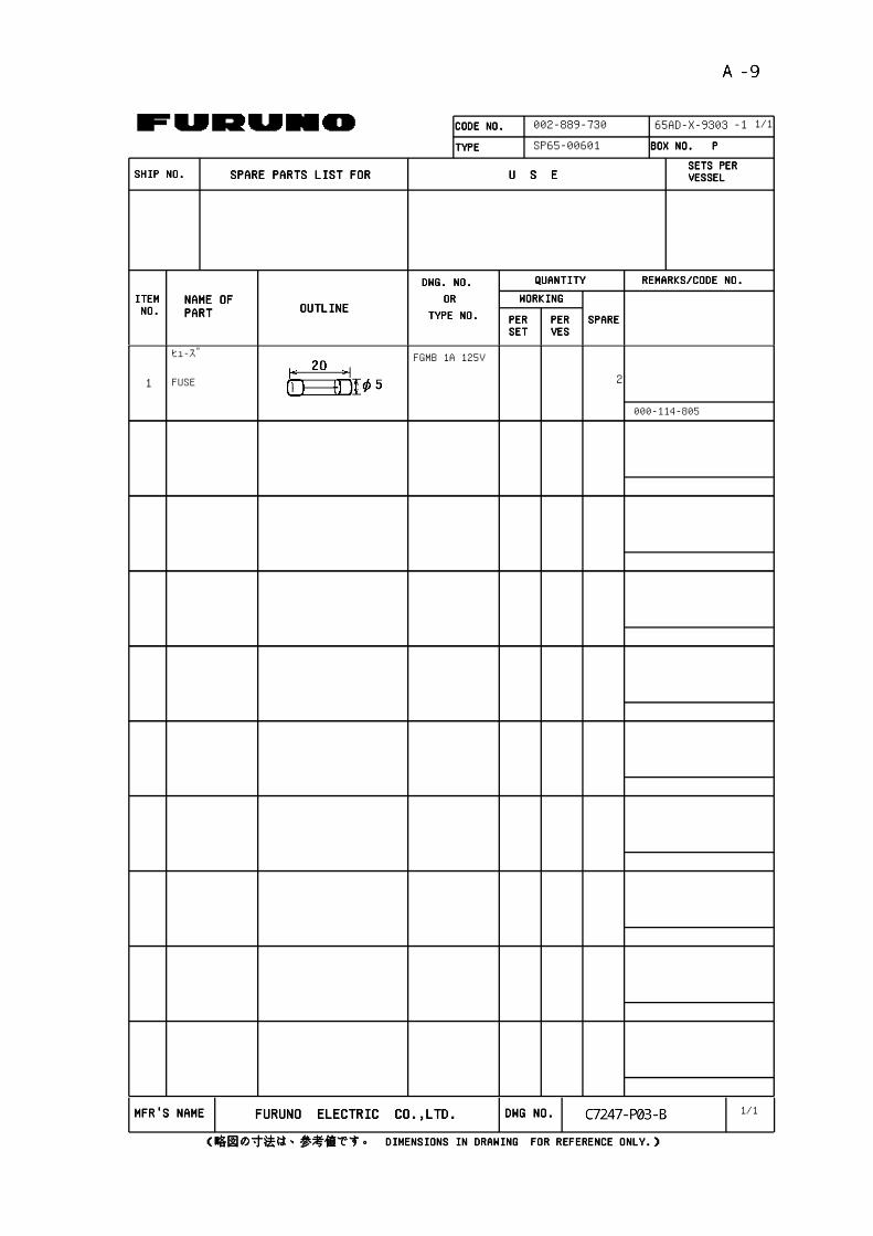
CODE NO.CODE NO.CODE NO.CODE NO. 002-889-730
TYPETYPETYPETYPE SP65-00601
ITEMITEMITEMITEM NO. NO. NO. NO.
NAME OF NAME OF NAME OF NAME OF PARTPARTPARTPART OUTLINEOUTLINEOUTLINEOUTLINE
DWG. NO. DWG. NO. DWG. NO. DWG. NO. OR OR OR OR
PERPERPERPERSETSETSETSET
PERPERPERPERVESVESVESVES
SPARESPARESPARESPARE
WORKINGWORKINGWORKINGWORKING
QUANTITYQUANTITYQUANTITYQUANTITY REMARKS/CODE NO.REMARKS/CODE NO.REMARKS/CODE NO.REMARKS/CODE NO.
BOX NO. P BOX NO. P BOX NO. P BOX NO. P
SHIP NO.SHIP NO.SHIP NO.SHIP NO. SPARE PARTS LIST FOR SPARE PARTS LIST FOR SPARE PARTS LIST FOR SPARE PARTS LIST FOR U S EU S EU S EU S ESETS PER SETS PER SETS PER SETS PER VESSELVESSELVESSELVESSEL
-1
TYPE NO.TYPE NO.TYPE NO.TYPE NO.
65AD-X-9303 1/1
ヒューズ FGMB 1A 125V
2FUSE
000-114-805
1
1/1MFR'S NAMEMFR'S NAMEMFR'S NAMEMFR'S NAME FURUNO ELECTRIC CO.,LTD.FURUNO ELECTRIC CO.,LTD.FURUNO ELECTRIC CO.,LTD.FURUNO ELECTRIC CO.,LTD. DWG NO.DWG NO.DWG NO.DWG NO.
(略図の寸法は、参考値です。 DIMENSIONS IN DRAWING FOR REFERENCE ONLY.)(略図の寸法は、参考値です。 DIMENSIONS IN DRAWING FOR REFERENCE ONLY.)(略図の寸法は、参考値です。 DIMENSIONS IN DRAWING FOR REFERENCE ONLY.)(略図の寸法は、参考値です。 DIMENSIONS IN DRAWING FOR REFERENCE ONLY.)


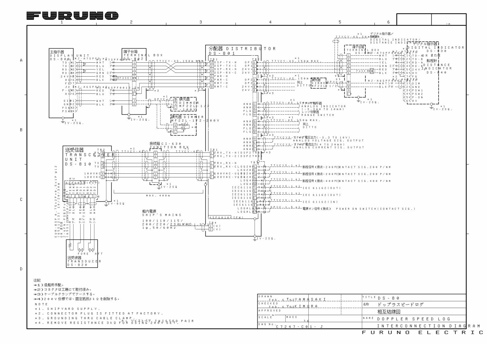
相互結線図
INTERCONNECTION DIAGRAM
DS-80
ドップラスピードログ
DOPPLER SPEED LOG
FURUNO ELECTRIC CO., LTD.
D
C
B
A
654321
P: ツイストペア TWISTED PAIR
DRAWN
CHECKED
APPROVED
SCALE MASS
DWG No.kg
TITLE
NAME
名称
*3)ケーブルクランプでアースする。
注記
*1)造船所手配。
*2)コネクタは工場にて取付済み。
*3. GROUNDING THRU CABLE CLAMP.
NOTE
*1. SHIPYARD SUPPLY.
*2. CONNECTOR PLUG IS FITTED AT FACTORY.
*4)200V仕様では、固定抵抗3kΩを削除する。
*4. REMOVE RESISTANCE 3kΩ FOR USING 200V SET.
T.YAMASAKIFeb. 6 '03
Feb. 6 '03 Y.KIMURA
TB213141516
17181920
OP2-HOP2-C
OP1-HOP1-C
*3
*3
24V+(H)24V-(C)
24V+(H)24V-(C)
1234
TB1DSP-TX-HDSP-TX-CDSP-RX-HDSP-RX-C
TB11516
1718
1920
TRX_TX-H(DSP2TRX)TRX_TX-C(DSP2TRX)
TRX_RX-HTRX_RX-C
100VAC-U(H)100VAC-V(C)
U
LV
*1
U
LV
調光器 DIMMERMF22L-1/2-200V
3k
*4
IV-2SQ.*1
FUSE(1A)
DS-802TERMINAL BOX端子台箱
*1
*1
TTYCY-4S,150m MAX.
TTYCY-4S,150m MAX.
3456
12
78910
*3
*3
DS-802
端子台箱TERMINAL BOX
*1 デジタル指示器/航程計DIGITAL INDICATOR/DISTANCE INDICATOR
IV-2SQ.*1
TTYCY-4S,50m MAX.
*1DPYC-1.5
調光器
MF22L-1/2DIMMER
MJ-A7SPFD
MJ-A6SPFD*2
OR またはBLU アオ
BLK クロ
YEL キ
WHT シロ
RED アカGRN ミドリ
シロクロ
WHTBLK
MJ-A7SPF0009,2m
MJ-A6SPF0003,2m
IV-2SQ.*1
同上DITTO
1234
ANA1-HANA1-CFLG1-HFLG1-C
5678
ANA2-HANA2-CFLG2-HFLG2-C
9101112
ANAV-HANAV-CANAC-HANAC-C
TTYCYS-1 *1
TTYCYS-1 *1
*3
*3
*3
レンジ切替器RANGE SWITCH
ANALOG VOLTAGE SIG. OUTPUT
ANALOG CURRENT SIG. OUTPUT
アナログ指示器ANALOG INDICATOR
アナログ電圧出力(-3.3 TO 10V)
アナログ電流出力(4 TO 20mA)
(-3.3mA TO 10mA)
*1
*1
RD-BRD-ATD-BTD-A
24V-P0VFGJ2
P-ON0V
P
P
DIMGNDPSW1PSW2
J1 MJ-A7SPFD *2
主指示器DISPLAY UNITDS-800
IV-2SQ.*1
BLU アオ
BLK クロ
YEL キ
WHT シロ
RED アカGRN ミドリ
RED アカBLU アオ
MJ-A6SPF0013,2m
WHT シロBLK クロ
MJ-A7SPF0009,2m
TTYCY-4S,150m MAX.
TTYCY-4S,150m MAX.
DITTO同上
分配器DS-801
DISTRIBUTORDS-830
DIGITAL INDICATORデジタル指示器
航程計
DS-840
DISTANCEINDICATOR
POWER ON SWITCH(CONTACT SIG.)
CONTACT SIG.200 P/NM
CONTACT SIG.200 P/NM
CONTACT SIG.400 P/NM
1234567891011121314
LOG200_2-HLOG200_1-CLOG200_1-H
LOG400-HLOG400-C
LOGALARM-HLOGALARM-C
航程信号(接点、200P)
航程信号(接点、200P)
航程信号(接点、400P)
TB3
LOG200_2-C
IEC61162_TX1-HIEC61162_TX1-CIEC61162_TX2-HIEC61162_TX2-CIEC61162_RX-HIEC61162_RX-C
電源オン信号(接点)
TTYCYS-1 *1
TTYCYS-1 *1
TTYCYS-1 *1
TTYCYS-1 *1
TTYCYS-1 *1
TTYCYS-1 *1
IEC 61162(OUT)
IEC 61162(OUT)
IEC 61162(IN)
DPYC-1.5 *1
21
34
56RX-C
RX-H
TX-HTX-C
MAX. 400m
*1TB2
100VAC-U(H)100VAC-V(C)
IV-8SQ*1
YELBLU
REDGRN
BLKWHT
キ アオ
アカ
ミドリ
クロ
シロ
1 2 3 4 5 6 7 8TB1
65P6020(KCP)
TEMP-H
TEMP-C
GND
GND
TD1-H
TD1-C
TD2-H
TD2-C
TTYCY-4S
TRANSCEIVER送受信器
DS-810UNIT
Z-6FN-PSB3Px0.5SQ
(65S1239)
EUR-BSP0.75x2P+0.5x1Pφ12
(65S1213)10/20/30m
ORまたは
FORE AFT
10/20/30m
TRANSDUCER送受波器
DS-820
21
34
56
接続箱JUNCTION BOX
CI-630
IV-2SQ*1
*1TTYCY-4S
*2
65P6010(JPW)
1φ,50/60Hz
船内電源SHIP'S MAINS
100/110/115/200/220/230 VAC
21TB4(U)(V)
IV-2SQ.
DPYC-1.5 *1
FUSE(1A)
78
RMT-HRMT-C
56
PWR-HPWR-C
56
1234
910
78
TTYCY-4S,150m MAX. *1
*3
P
P
P
P
*3
DPYC-1.5
MF22L-1/2-100V
DIMMER調光器
1234567
56
1234
MJ-A6SPFD *2
1234567
123456
J2
RD-BRD-ATD-BTD-A
24V-P0VFG
DIMGNDPSW1PSW2P-ON0V
J1
C7247-C01- J