14
DORMA Installation Manual Door Module DORMA
DORMA Installation ManualDoor ModuleDORMA


3
Door module Table of Contents
Table of Contents
1. General Information. . . . . . . . . . . . . . . . . . . . . . . . . 4
1.1 Preface . . . . . . . . . . . . . . . . . . . . . . . . . . . . . . . . . 5
1.2 Correct use . . . . . . . . . . . . . . . . . . . . . . . . . . . . . . 5
1.3 Safety instructions and warnings . . . . . . . . . . . . . . . . 5
1.4 Further Sources of Information . . . . . . . . . . . . . . . . 6
1.5 Disposal . . . . . . . . . . . . . . . . . . . . . . . . . . . . . . . . 6
1.6 Functional description . . . . . . . . . . . . . . . . . . . . . . 6
1.7 Package contens . . . . . . . . . . . . . . . . . . . . . . . . . . 7
1.8 Installation accessories (optional) . . . . . . . . . . . . . . 7
2. Assembly . . . . . . . . . . . . . . . . . . . . . . . . . . . . . . . 8
2.1 Connections . . . . . . . . . . . . . . . . . . . . . . . . . . . . . 8
2.1.1 Power supply . . . . . . . . . . . . . . . . . . . . . . . . . . . 8
2.1.2 Power supply loop through . . . . . . . . . . . . . . . . . 8
2.1.3 Digital inputs . . . . . . . . . . . . . . . . . . . . . . . . . . . 9
2.1.4 Relay outputs. . . . . . . . . . . . . . . . . . . . . . . . . . . 9
2.1.5 Communication interface . . . . . . . . . . . . . . . . . . 9
2.2 Final installation . . . . . . . . . . . . . . . . . . . . . . . . . 10
3. Commissioning . . . . . . . . . . . . . . . . . . . . . . . . . . . 11
3.1 Settings . . . . . . . . . . . . . . . . . . . . . . . . . . . . . . . 11
3.1.1 Bus address . . . . . . . . . . . . . . . . . . . . . . . . . . . 11
3.1.2 Terminating resistors. . . . . . . . . . . . . . . . . . . . . 11
3.2 Visual displays . . . . . . . . . . . . . . . . . . . . . . . . . . 12
3.2.1 Relay outputs. . . . . . . . . . . . . . . . . . . . . . . . . . 12
3.2.2 Digital inputs . . . . . . . . . . . . . . . . . . . . . . . . . . 12
3.2.3 Online . . . . . . . . . . . . . . . . . . . . . . . . . . . . . . . 12
3.3 Tamper monitoring . . . . . . . . . . . . . . . . . . . . . . . 12
EC Declaration of Conformity . . . . . . . . . . . . . . . . . . . 13
4. Technical data . . . . . . . . . . . . . . . . . . . . . . . . . . . 14

Door module 1. General Information
4
The information provided in these assembly instructions may be modified without prior notification. All previous versions cease to be valid with the publication of these instructions.
The information in these assembly instructions has been compiled to the best of our knowledge and in good faith. DORMA accepts no liability for the correctness and com-pleteness of the details provided.
In particular, DORMA cannot accept liability for any conse-quential damages due to incorrect or incomplete informa-tion.
The recommendations for installation made in this manual are based on the assumption that prevailing basic conditions are favourable. DORMA accepts no liability for the perfect functioning of the Door module in external, non-system environments.
Despite every effort to prevent mistakes, they can never be completely avoided. Therefore, we would be grateful to receive notification of any errors or omissions.
DORMA accepts no liability for the information included in this document being free of protected third party rights. DORMA does not provide any licences to its own or to third party patents or other protected rights with this document.
This manual or sections of it may not be reprinted, copied or distributed to third parties, other than for your own use, with-out the approval of DORMA Time + Access GmbH.
All rights reserved.DORMA Time + Access GmbHPostfach 21 01 8553156 Bonnhttp://www.dorma-time-access.deE-Mail [email protected]
© Copyright 2011 by DORMA Time + Access GmbH
Drawing no.: 1098G-00-B1-ENStatus: 07/15 V2.21

5
Door module 1. General Information
1.1 Preface
This installation manual is intended to assist you in con-necting and commissioning the Door module.
1.2 Correct use This device is intended exclusively for use in attendance recording and access control systems. Further details are described in chapter 1.6. Use for any other purpose than that described is not permitted.
1.3 Safety instructions and warnings
This device has been constructed and tested in accordance with all currently applicable technical regulations. It left the factory in perfect condition in terms of safety and reliability. To maintain this condition and to ensure risk-free operation, the instructions and warnings given in this operating manual must be observed by the user.
• Installation and assembly of electrical equipment may only be carried out by a qualified electrician!
• During assembly, please ensure that the requirements laid down in the relevant equipment safety standard for the unit are adhered to since violating them could affect the safety of the device.
• Before switching on, ensure that the operating and con-trol voltages connected do not exceed the permissible values in accordance with the technical data!
• This unit conforms to EN 60950, protection class III.
• The units must be operated with safety extra low voltage (SELV)!
Electromagnetic compatibility:• The device is designed for use in residential, business
and commercial areas and conforms to EN 61000-6-2 and EN 61000-6-3.
• The PCB can be damaged by static electricity discharge, so the relevant precautionary measures must be observed (grounding etc.)!
Caution
• These units may only be operated when mounted!
• The locking screws on unassigned connection terminals must be screwed in as far as they will go.
• If it is suspected for any reason that the operation of the device could represent a hazard, then it must be removed from use and precautions taken to prevent unintentional operation!
• If the failure or malfunction of the unit might result in injury to persons or animals or in damage to works equip-ment, this must also be prevented by taking additional safety measures (limit switch, safety devices, etc.).
• Switch off the power supply before opening the device.
Door module 1. General Information
6
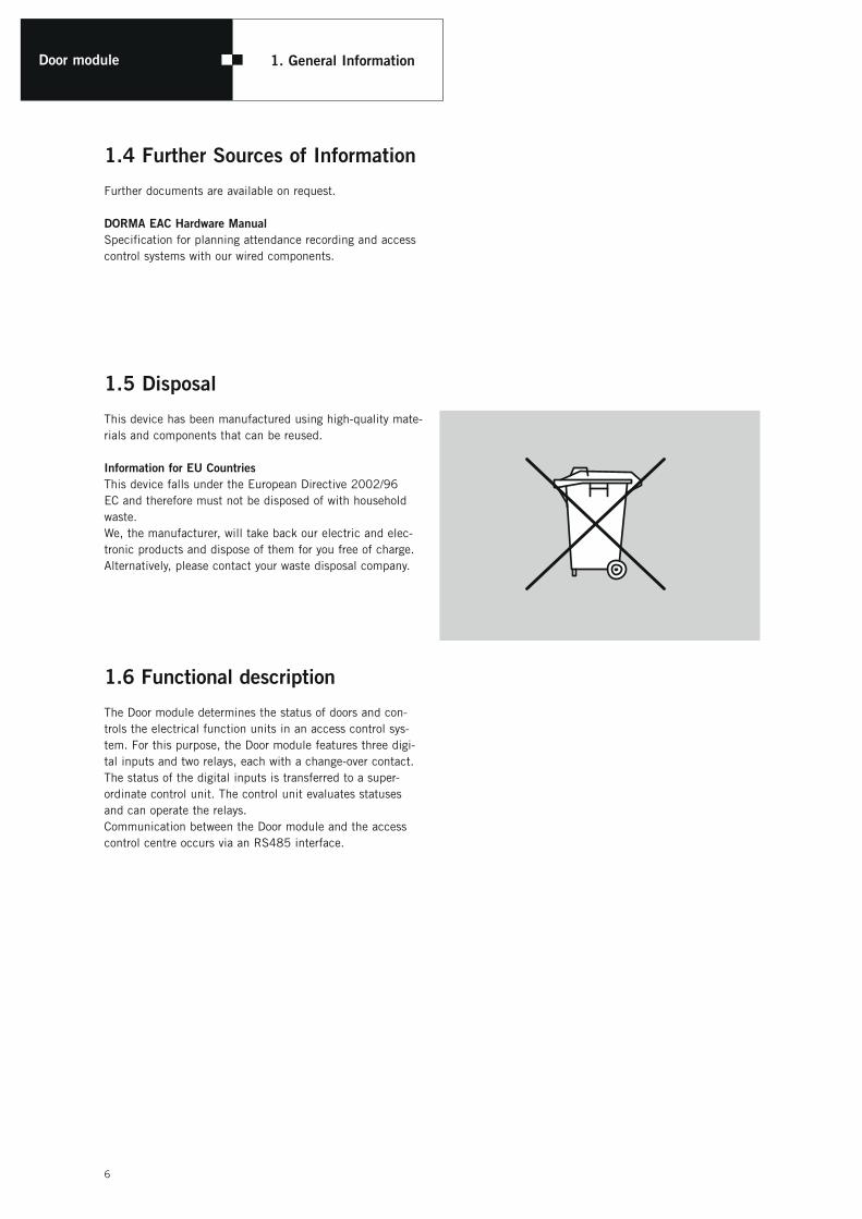
1.4 Further Sources of Information
Further documents are available on request. DORMA EAC Hardware ManualSpecification for planning attendance recording and access control systems with our wired components.
1.5 Disposal
This device has been manufactured using high-quality mate-rials and components that can be reused.
Information for EU CountriesThis device falls under the European Directive 2002/96 EC and therefore must not be disposed of with household waste. We, the manufacturer, will take back our electric and elec-tronic products and dispose of them for you free of charge. Alternatively, please contact your waste disposal company.
1.6 Functional description
The Door module determines the status of doors and con-trols the electrical function units in an access control sys-tem. For this purpose, the Door module features three digi-tal inputs and two relays, each with a change-over contact. The status of the digital inputs is transferred to a super-ordinate control unit. The control unit evaluates statuses and can operate the relays. Communication between the Door module and the access control centre occurs via an RS485 interface.

7
Door module 1. General Information
1.7 Package contents
A 1x Door moduleB 1x bezel
C 2x jumperD 1x manual
1.8 Installation accessories (optional)
A Surface-mount casing 1)
The surface-mount casing is used to surface-mount the Door module.
C System55 combination frame 1) 2)
The combination frame is always required whenever the door module is flush-mounted.
You can find more installation accessories in our catalogues.
A B
1) Available in different colours 2) Single or multiple frame
A
C
D
DORMA InstallationshandbuchS6R-DM (Doormodule)
D
ST101
SW101
online
Relay
Digital InBU101
12
12
3
B
Door module 2. Assembly
8
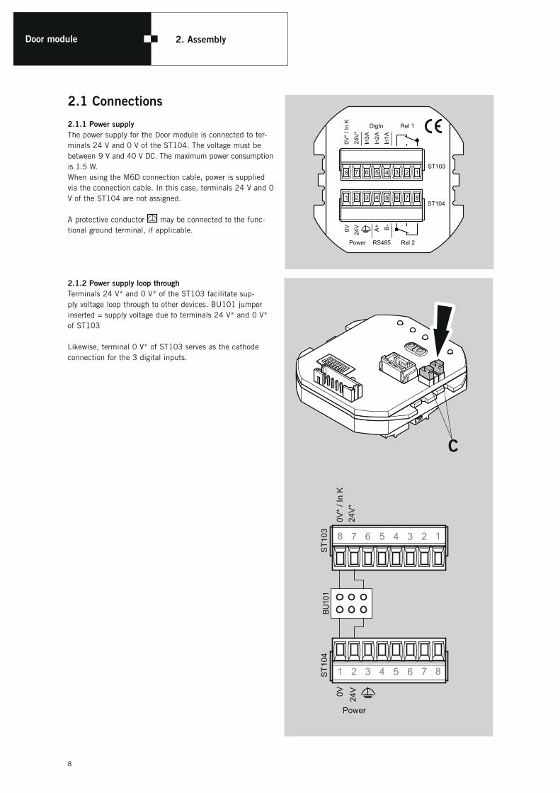
2.1 Connections
2.1.1 Power supplyThe power supply for the Door module is connected to ter-minals 24 V and 0 V of the ST104. The voltage must be between 9 V and 40 V DC. The maximum power consumption is 1.5 W. When using the M6D connection cable, power is supplied via the connection cable. In this case, terminals 24 V and 0 V of the ST104 are not assigned.
A protective conductor may be connected to the func-tional ground terminal, if applicable.
2.1.2 Power supply loop throughTerminals 24 V* and 0 V* of the ST103 facilitate sup-ply voltage loop through to other devices. BU101 jumper inserted = supply voltage due to terminals 24 V* and 0 V* of ST103 Likewise, terminal 0 V* of ST103 serves as the cathode connection for the 3 digital inputs.
C
ST101
SW101
online
ST105
RelayDigital In
BU101
Rel 2RS485
Rel 1DigIn
ST10487654321
12345678ST103
In1A
In2A
In3A
24V
*
0V*
/ In
K
Power
B-
A+
24V0V
12123
ST1
04
8 7 6 5 4 3 2 1
1 2 3 4 5 6 7 8
ST1
03
24V
*0V
* / I
n K
24V0V
Power
BU10
1

9
Door module 2. Assembly
2.1.3 Digital inputsThe three digital inputs of the Door module are located on ST103. The digital inputs are plus-switching and their con-tact load is a maximum of 10 mA. They can also be used with AC voltage. The switching threshold is: Active at U > 16VDC, 15VAC Passive at U < 4VDC, 4VAC
2.1.4 Relay outputsBoth relay outputs of the Door module are located on ST103 and ST104. Their maximum load capacity is 60 W. Maximum DC values: 45V or 2A (SELV) Maximum AC values: 30V or 2A (SELV) The diode shown is used as the free-wheel diode. When connecting alternating current, it must be replaced with an RC element or a transorb diode (item no. 1900001662276) for interference suppression.
2.1.5 Communication interfaceThe RS485 bus line is connected to ST104 terminals A+ and B- .
ST103
Rel1
Rel2RS485
ST104
8 7 6 5 4 3 2 1
B-
A+
24V0V
Power
1 2 3 4 5 6 7 8
+
-external power supply
ST103
Rel1
Rel2RS485
ST104
8 7 6 5 4 3 2 1
B-
A+
24V0V
Power
1 2 3 4 5 6 7 8
+
-external power supply
Rel 1DigIn
8 7 6 5 4 3 2 1ST103
In1A
In2A
In3A
24V
*0V
* / I
n K
+
-
Rel 1DigIn
8 7 6 5 4 3 2 1ST103
In1A
In2A
In3A
24V
*0V
* / I
n K
External power supply
Power supply via loop through

Door module 2. Assembly
10
2.2 Final installation
1.
4.
ST101
SW101
online
Relay
Digital InBU101
12
12
3
2.
3.
ST101
SW101
online
Relay
Digital InBU101
12
12
3
ST101
SW101
online
Relay
Digital InBU101
12
12
3
A
B
5.
5.

11
Door module 3. Commissioning
ST101
SW101
online
ST105
RelayDigital In
BU101
Rel 2RS485
Rel 1DigIn
ST10487654321
12345678ST103
In1A
In2A
In3A
24V
*
0V*
/ In
K
Power
B-
A+
24V0V
12123
SW101
3.1 Settings
3.1.1 Bus address
SW101 1 2 3 4 5 6 7 8
Function Bus addresstamper
monitoringBus connection resistor
Default on off off off off on off off
Adjustable x
Switch SW101 Adresse(dezimal)
1 2 3 4 5
off off off off off 00*
on off off off off 01
off on off off off 02
on on off off off 03
off off on off off 04
on off on off off 05
off on on off off 06
on on on off off 07
off off off on off 08
on off off on off 09
off on off on off 10
on on off on off 11
off off on on off 12
on off on on off 13
off on on on off 14
on on on on off 15
Switch SW101 Adresse(dezimal)
1 2 3 4 5
off off off off on 16
on off off off on 17
off on off off on 18
on on off off on 19
off off on off on 20
on off on off on 21
off on on off on 22
on on on off on 23
off off off on on 24
on off off on on 25
off on off on on 26
on on off on on 27
off off on on on 28
on off on on on 29
off on on on on 30
on on on on on 31
3.1.2 Terminating resistorThe bus terminating resistors must be switched on ifthe door module is the first or last bus device.
The bus address can be set with the 8-pin DIP Switch SW101.31 addresses are available.The address 00 is reserved for the control unit.

Door module 3. Commissioning
12
3.3 Tamper monitoring
A reflection light barrier detects the removal of the front bezel.
3.2 Visual displays
3.2.1 Relay outputs
LED Meaning
off Relay 1, 2 is not active
yellow Relay 1, 2 is active
3.2.2 Digital inputs
LED Meaning
off Digital input 1…3 is not active
yellow Digital input 1…3 is active
3.2.3 Online
LED Meaning
yellow The online LED illuminates as long as the Door module is being polled by the super-ordinatecontrol unit.
yellowflashing
If the Door module is not polled for over 15 seconds, the online LED flashes
ST101
SW101
online
ST105
RelayDigital In
BU101
Rel 2RS485
Rel 1DigIn
ST10487654321
12345678ST103
In1A
In2A
In3A
24V
*
0V*
/ In
K
Power
B-
A+
24V0V
12123
3.2.13.2.2
3.2.3
The tamper monotoring works only, if the switch 101-6 set to on.

Door moduleEG KonformitätserklärungEC Declaration of ConformityCE Déclaration de conformité
13

Door module 4. Technical data
14
Supply voltage
9 VDC to 40 VDC (SELV)
Power consumption max 60 mA, max. 1.5 W
Interface RS485DP1 protocol
Outputs: 2 x relay: maximum load 60 W 45 VDC/2 A (SELV) 30 VAC/2 A (SELV)
Digital inputs: 3x optocouplers (plus-switching)Loading: 36 VDC/max 10 mA 24 VAC/max 10 mA
Switching thresholds: active at 16 VDC or 15 VAC passive at 4 VDC or 4 VAC
Anti-tamper contactReflex light barrier
Ambient conditionsOperating temperature range: -20 °C to +50 °C Storage temperature range: -20 °C to +70 °C Humidity range: 0 to 80%, non-condensing
General designEN 60950-1, protection class |||
Protection ratingIP 30
Resistance to interferenceEN 61000-6-2
Interference emissionsEN 61000-6-3 Emission standard for residential, commercial and light-industrial environments
Dimensions (W x H x D) 52 x 52 x 29 (mm)
Weight 50 g
We reserve the right to make technical modifications and improvements that assist the further development of our equipment.
DORMA Time + Access GmbH Postfach 21 01 85 • D-53156 Bonn • Mainzer Straße 36-52 • D-53179 Bonn Tel. +49 (0) 2 28/85 54-0 • Fax +49 (0) 2 28/85 84-1 75 • www.dorma-time-access.de
DORMA Deutschland GmbH Postfach 40 09 • D-58247 Ennepetal • DORMA Platz 1 • D-58256 Ennepetal Tel. +49 (0) 23 33 / 793-0 • Fax +49 (0) 23 33 / 79 34 95 • www.dorma.com


