®CBS 20 STANWIX STREET, 10'" FLOOR PITTSBURGH, PENNSYLVANIA 15222 Dorothy M. AIke Vice President, Environmental Projects 412.642.2562 Telephone 412.642.3014 Fax dottie.aike @ cbs.com July 27, 2010 UPS OVERNIGHT MAIL Mr. Thomas Alcamo U.S. Enviromnental Protection Agency Region 5 77 West Jackson Boulevard Mailstop HSRL-6J Chicago, IL 60606 RE: ICS Excess Flow Treatment System - Vendor Submittal Dear Tom, As discussed on our telephone call on Friday, July 23, enclosed please a copy of the Calgon Carbon submittal for the ICS Excess Flow Treatment System. Very-^ly yours, Dorothy M. AIke BP-10-0047 cc: John Bassett (w/enclosure) Jessica Fliss (w/enclosure) us EPA RECORDS CENTER REGION 424743
Transcript
regCBS 20 STANWIX STREET 10 FLOOR PITTSBURGH PENNSYLVANIA 15222
Dorothy M AIke Vice President Environmental Projects
4126422562 Telephone 4126423014 Fax
dottieaike cbscom
July 27 2010
UPS OVERNIGHT MAIL
Mr Thomas Alcamo US Enviromnental Protection Agency Region 5 77 West Jackson Boulevard Mailstop HSRL-6J Chicago IL 60606
RE ICS Excess Flow Treatment System - Vendor Submittal
Dear Tom
As discussed on our telephone call on Friday July 23 enclosed please a copy of the Calgon Carbon submittal for the ICS Excess Flow Treatment System
Very-^ly yours
Dorothy M AIke BP-10-0047
cc John Bassett (wenclosure) Jessica Fliss (wenclosure)
us EPA RECORDS CENTER REGION
424743
CALGON CALQON CARBON CORPORATION
500 CALGON CARBON DRIVE bull PITTSBURGH PA 15205 USA TELEPHONE 1-412-787-6700 bull FAX 1-412-787-6819
wwwcalgoncarboncom
To CBS Corporation 20 STANWIX ST -10^ FLOOR PNC CENTER PITTSBURGH PA 15222
ATTENTION MR RUSS CEPKO
TELEPHONE 412-642-2569
E-MAIL
RECEIVED MAY 1 1 2010
DATE CCC PROJECT
MAY 72010 LM-10048CBS1
CBS-PGH PuRCh^ASE O R D E R NUMBER BL-0397 LITIGATION
FAX
CELL
REFERENCE CBS CorpClark Dietz - Illinois Central Springs Treatment Facility
WE ARE TRANSMITTING THE FOLLOWING Enclosed D Separately DCD
Kl Submittals D Other
D Drawings n Change Order
D Operation and Maintenance Manuals D Specifications D Preliminary Drawings
CQIIES
1
bull bull bull
NuMi3ER
bdquo bull bull bull
TRUVJSICN1
bull -bull-
y ^ - l bdquo bdquo 1 u - I MCoolJUj-lIWIN bullbdquobull )bull iw v bull-
Submittal Manual - Model 12 Adsorber Systems
c J J ] J s y T j r I-V^- r bullgt^T^
T H E S E DOCUMENTS A R E TRANSMITTED A S P E R T H E FOLLOWING
K For Approval D Approved As Submitted D For Your Information ^ For Your Use D Returned For Correction Q Released To Fabricate
K As Requested D Released For Construction
TflanA fftetfm^
Mark Meyers Project Manager
Telephone 1-412-787-6893 Fax 1-412-787-6319
E-Mail Mmeyerscalgoncarbon-uscom
SENT VIA FEDEX n Copy to Field Service
CALGON CARBON CORPORATION bull COPYRIGHT 2004 bull ALL RIGHTS RESERVED bull PROPRIETARY AND CONFIDENTIAL
SALOON CARBON CORPORATION
ubmittal Manual MODEL 12 GRANULAR
ADSORPTION SYSTI
PREPARED B Y Calgon Carbon Corporation
PITTSBURGH PA
CALGON CARBON PROJECT NUMBER
CUSTOMER PURCHASE ORDER NUMBER
LM-10048CBS1
BL-0397
DATE OF PRINT MAY 2010
THIS MANUAL IS THE PROPERTY OF CALGON CARBON CORPORATION AND IS NOT TO BE REPRODUCED IN WHOLE OR IN PART NOR EMPLOYED FOR ANY PURPOSE OTHER THAN SPECIFICALLY PERMITTED IN WRITING BY C A L G O N C A R B O N CORPORATION
F
CAL60N
ubmittal Manual MODI
FOR
BLOOMINGTON SL
PREPARED BY Calgon Carbon Corporation
PITTSBURGH PA
CALGON CARBON PROJECT NUMBER
CUSTOMER PURCHASE ORDER NUMBER
LM-10048CBS1
BL-0397
DATE OF PRINT MAY 2010
THIS MANUAL IS THE PROPERTY OF CALGON CARBON CORPORATION AND IS NOT TO BE REPRODUCED IN WHOLE OR IN PART NOR EMPLOYED FOR ANY PURPOSE OTHER THAN SPECIFICALLY PERMITTED IN WRITING BY C A L G O N C A R B O N CORPORATION
w
SUBMITTAL MANUAL MODEL 10 amp 8 GRANULAR CARBON ADSORPTION SYSTEM
CALOON CARBON COHPOfiATION
F CONTENT
PROCESS DESCRIPTION bdquobdquo bdquobdquoSECTION 1
^ ^ f i ^ i r I^S V ^ I iJ D B o a a o B B O o a a D a a D a a g a D n o D D a a a a a D D a B a D D s a a a D D D D D D D t f a D a a a D D a B B a a a a a a i i a ^ ^ B V ^ II I V ^ l ^
SPECIFICATIONS amp CATALOG CUTS SECTION 3
VESSEL LINING SECTION
PAINT SPECIFICATIONS SECTION
DRAWINGS SECTIONS
CALGON CARBON CORPORATION bull COPYRIGHT 2003 bull ALL RIGHTS RESERVED
PROCESS DESCRIPTION ^ ^ copy ^ k MODEL 12 SINGLE GRANULAR CARBON ADSORBER
CALQON CARBON CORPORATION
SECTION 1 = PROCESS DESCRIPTION
The Model 12 Single Adsorber is a free standing vertical pressure vessel containing 20000 pounds of granular activated carbon The vessel is complete with underdrain Process piping and carbon transfer piping is shipped loose for installation in the field
Granular activated carbon is delivered to the site in bulk trailers for unloading directly as a water slurry into the empty adsorber
The stream to be treated is pumped to the adsorber at a flow rate compatible with the design capacity of the unit The adsorber is operated in a downflow direction
In single stage operation the influent flow is directed to the vessel through the inlet line Initially the impurities are adsorbed onto the carbon in the upper portion of the bed As this top layer of carbon becomes saturated adsorption takes place lower in the bed Eventually all the carbon in the adsorber becomes saturated and the contaminant concentration of the effluent from the adsorber increases until it approaches or equals the influent concentration When contaminant breakthrough is detected from the vessel flow is stopped and the carbon is replaced
When the carbon in a vessel is spent an empty trailer is sent to the site to remove the spent carbon The spent carbon is transferred from the adsorber to the bulk trailer by first filling the adsorber with water The adsorber is then pressurized using compressed air as the motive force to facilitate the carbon transfer to the trailer
Once the spent carbon transfer operation is completed a charge of fresh carbon can be transferred into the empty adsorber This is accomplished by filling the bulk trailer with water and placing a water cushion in the adsorber The bulk trailer is then pressurized with compressed air to facilitate the carbon transfer into the adsorber
Backwashingbackflushing is usually required when the pressure drop across an adsorber increases by 5 to 10 psi during normal operation
Model 12 units come equipped with a 30deg internal cone This internal cone offers many advantages such as ease of carbon removal and good flow distribution through the nozzle underdrain
To prevent damage to the vessels due to over pressurization pressure relief devices graphite rupture disks are provided in the adsorber vent lines The rupture disks rated at the design pressure of the vessels
After start-up records should be kept of pertinent data such as flow rate pressure drop across each bed total dissolved solids temperature pH andor specific performance requirements such as toxicity BOD COD and TOC organic contaminant levels
PAGE1
SEQUENCE OF OPERATION
MODEL 12 SINGLE GRANULAR CARBON ADSORBER CMjaOH CARBON CORPORA^ON
SEQUENCE OF OPERATION
1 PRE-OPERATION CHECK-OUT
All equipment and systems affiliated with the granular carbon adsorption system such as pumps filters etc should be checked out according to the manufacturers instructions Specific activities to complete before operating the adsorption equipment should include the following
1 Check all piping connections for proper installation and tightness 2 Ensure that all gauges and instruments are functional and installed
correctly Re-zero or re-calibrate if necessary 3 Close all valves in the adsorber piping system
For potable water treatment installations the client will be responsible for cleaning and disinfecting the vessels and piping prior to filling the system with carbon The procedures to complete this step in the installation process are the responsibility of the client
2 FILLING AN ADSORBER WITH CARBON
After the system has been checked the adsorbers are ready to be filled with granular activated carbon The carbon is transferred to the adsorbers as a water slurry from Calgon Carbon trailers
3 WETTING (DEAERATING THE CARBON)
In a typical bed of virgin carbon the pore volume is approximately 40 of the bed volume Carbon which is shipped dry will contain air in these pores Therefore the carbon must be properly wetted prior to being placed on stream If this is not done the air within these pores will displace into the void spaces between the carbon particles during operation and cause high pressure drop and channeling in the adsorbers These problems can cause premature breakthrough of contaminants Air will not migrate out of the bed during normal downflow operation
The fime required for wetting is a funcfion of liquid temperature and viscosity Generally a minimum wetfing period of 24 hours is required using water at ambient temperatures although a period of up to 72 hours is preferred for complete wetfing After wetting backwashable adsorbers should be backwashed to remove air and segregate the carbon by size
PAGEI
SEQUENCE OF OPERATION MODEL 12 SINGLE GRANULAR CARBON ADSORBER
CALQON CARBON CORPORATION
As an alternafive the Calgon Carbon Service trailer containing fresh carbon may be filled with water and allowed to stand for several hours When the fresh carbon is transferred to the adsorber the adsorber should be backwashed to eliminate any remaining air
After the carbon has been wetted the adsorber should be drained and then backfilled unfil water flows out the system vent line The adsorber should be filled up-flow at 2 gpmft^ maximum For a Model 12 System this is 220 gpm maximum
If the unit must be placed on-stream before the carbon has been wetted the adsorbers should be drained and backfilled when the pressure drop becomes prohibifive or after two days of operation whichever occurs first
4 BACKWASHING A N D B A C K F L U S H I N G
41 BACKWASHBACKFLUSH GENERAL
Backwashing and backflushing are procedures involving running clean contaminant-free water upflow through the adsorber Backwashing or backflushing of a carbon bed can be done after fresh carbon has been transferred into an adsorber and wetted or during operation to remove sediment from the top of the bed
If the adsorbers are to be backwashed during operafion they should be backwashed prior to startup The reasons for backwashing before placing fresh carbon on-line are to
1 Size segregate the carbon so subsequent backwashing will return the carbon to the same relafive posifion in the bed
2 Remove any remaining air from the bed 3 Remove carbon fines which can in some cases lead to excessive
pressure drop and flow restricfion
Backwashing is done during operafion to remove
1 Sediment from the top of the bed 2 Carbon fines that may be plugging the underdrain nozzles 3 Air that is binding the bed The need to backwash is indicated by an
increased bed pressure drop
PAGE 2
SEQUENCE OF OPERATION MODEL 12 SINGLE GRANULAR CARBON ADSORBER
CALOON CARBON CORIORAnON
Backwashing an adsorber results in expanding the carbon bed removing air suspended solids and carbon fines and classifying the carbon particles The backwash flow rate depends upon the carbon particle mesh size and the water temperature (refer to the bed expansion curve in Secfion 8) Model 12 units are designed with significant straight side height to permit 30 bed expansion and the selected backwash rate should limit the bed expansion to a maximum of 25
In a system that is not designed for backwashing an operafion termed backflushing can be used to remove fines from the upper portion of the bed This operafion will not remove fines from the lower portion of the bed because it does not expand the bed Expansion of the bed allows the fines at the bottom of the bed to move to the top However fines do not always cause high pressure drop and their removal is not always necessary
The backflushing rate is 2 to 3 gpmft^ and this is not significant enough to expand the carbon bed For the Model 12 adsorber this is a flow rate from 220 gpm to 330 gpm Flow rates of less than 330 gpm will not expand the bed therefore size segregafion of the bed will not occur The fime required for backflushing is 30 to 45 minutes
Normally when backwashing or backflushing a clean external water source is used The stream should be compafible with the system and free of suspended solids and organic contaminants which might affect adsorpfion If necessary effluent from the adsorber system may be used as the water source In this case a tank with storage capacity for 15 minutes of backwash water (20000 gallons) will be necessary
When normal downflow operafion is started after backwashing the inifial 5 to 15 minutes of effluent flow will be dark due to a small quanfity of fines Under normal operafing condifions this condifion will clear up
42 BACKWASHING A N ADSORBER
In this mode a clean external source is used as the source for the backwash water Note that the lead adsorber is taken out of service while the backwashing procedure takes place It is recommended that the enfire system be taken ofl-line to retain all process condifions However for confinuous flow the lag adsorber can remain on-line while the lead bed is being backwashed
For a system operafing in parallel only the vessel needing backwashed should be taken off-line when backwashing is required
PAGE 3
SEQUENCE OF OPERATION ^ ^ L O O M MODEL 12 SINGLE GRANULAR CARBON ADSORBER
CAtOON CARBON CORPORATION
1 Isolate the adsorber to be backwashed 2 Open the vent valve 3 Open the backwash water inlet valve and start the backwash
pump Backwash flow should be increased to design flow gradually avoiding water hammer
The backwash water enters the vessel through the effluent line and flows up through the underdrain and the carbon bed The backwash water discharge from the vent line should be observed for clarity to determine the duration of backwashing Backwashing for high pressure drop should take approximately 10 minutes If excessive sediment and turbidity exists in the untreated water the backwashing fimes may have to be increased to 15 minutes A fresh carbon fill should be backwashed to classify the carbon The fime required for this step is approximately 15 minutes or unfil the backwash discharge is free of fines
43 RE-STARTING SYSTEM AFTER BACKWASHING
The valve sequence given below describes the steps taken to bring a system onshyline after backwashing
1 Close the backwash water inlet valve 2 Close vent valve 3 Open influent valve 4 Close influent valve
5 START^UP
51 PARALLEL FLOW
The following sequence of steps should be followed to bring an adsorpfion system on-line in the parallel mode
1 Check that all the valves in the adsorpfion system are closed
2 Open the valves in the eflluent lines from the adsorbers 3 Start the feed pump and open the valve in the pump
discharge line 4 Slowly open the valve in the influent line to one adsorber and
allow the pressure to increase to the operafing level 5 Slowly open the valve in the influent line to the other
adsorber and allow the pressure to increase to the operafing level
PAGE 4
SEQUENCE OF OPERATION d^^^oow MODEL 12 SINGLE GRANULAR CARBON ADSORBER
CALOON CARBON CORPORATION
6 Open the 34 valve located on the side wall of each vessel to bleed off any air that is trapped underneath the internal cone
At this point flow should be established downflow through both vessels and they will be on-line in parallel
Set the flow rate to the system at the desired value after flow is established to the unit The flow control meters and control instrumentafion will be provided by the client as required for the system
In order to obtain full ufilization of the carbon and prevent air entrapment and channeling in the bed the water level must remain above the carbon bed To prevent the bed from draining due to gravity or loss of infiuent supply a vacuum break (anfi-siphon) loop or backpressure should be included by the client in the effluent piping This start-up sequence assumes that an anfi-siphon loop is present in the effluent piping If no anfi-siphon loop or backpressure is present start the system by starting the pump and opening the valves in the opposite order of the sequence given previously (ie open the influent valves first followed by the effluent valves)
For parallel operafion flow is established to each vessel by opening the valves as indicated previously Changing the flow to one vessel may result in a flow change to the other vessel on the skid This occurs because the vessels share a common influent and effluent line Flow meters can be installed in the individual influent lines to each vessel to balance the flow to each unit if required
6 STEADY STATE OPERATION
Once flow is established to both vessels and the flow rate is set no further adjustments are made during normal operafion The operator should establish a roufine to check the adsorbers and to collect operafing data This data can be used to establish a maintenance schedule to determine when backwashingbackflushing is necessary or to determine when fresh carbon is needed
PAGES
SEQUENCE OF OPERATION ^ c k m o M MODEL 12 SINGLE GRANULAR CARBON ADSORBER
CALOON CARBON CORPORATION
61 MONITORING
Sample connecfions are provided on the influent and effluent lines from each vessel to take periodic samples for analysis
Pressure gauges are provided to determine the pressure drop across each carbon bed Taking periodic pressure readings will provide the operator with historic data for troutjieshoofing purposes In the event that operafing condifions change the operator has the capability of taking correcfive acfion
62 VALVE OPERATION
All valves should be operated in a slow and even mofion Abrupt opening and closing of the valves can shock the system Since complete shut-off of flow while a pump is operafing could cause damage to the pump the valves should be operated in the proper sequence in order to always maintain flow through the system
7 SHUTDOWN
71 SHORT TERM SHUTDOWN
For short durafion shutdowns lasfing less than one or two weeks litfie needs to be done Close all valves in the adsorber piping system and open the vent line valves on each vessel The feed pumps should be shut down and the valves closed in the lines to and from the pumps Any drain valves in the pump casing should be opened for the durafion of the shutdown Freeze protecfion measures such as draining lines at the low points should be taken when there is a chance of freezing Freeze protection measures are usually the responsibility of the client
72 EXTENDED SHUTDOWNS
For extended shutdowns in addifion to the steps in Secfion 71 the adsorbers should be drained of all water
When the adsorbers are started up again the carbon beds may require disinfecfion Once the disinfection is complete backwashable adsorbers should be backwashed prior to start-up
After disinfecfion bring the adsorber back on-line in the downflow mode monitor the effluent for coliform count and monitor the pressure drop
PAGE 6
CALQON
ECTION 2
CARBON
^ u
bull j L u -I m j - M - mdash J---- bull - mdash bull T n - - J ^ - - U ^ l l - - j j u ^ i _ - j _ _ ^ i t j r C T |
I I I I I I I I c I I I I 1 r
Mak ing W a t e r and A i r Safer and C leaner CALGON CARBON CORPORATION
OSR=euro 8X30 Granu la r Ac t i va ted Carbon
Descr ip t ion DSR-C IS a grade of reactivated carbon designed for the removal of organic contaminants from industrial wastewater or process water The carbon is manufactured by the reactivation of bituminous coal-based products to produce a high-density high surface area durable product capable of withstanding repeated cycles of use and reactivation DSR-C is effective in a wide range of applications and fluctuating flows providing reliable removal of dissolved organic compounds and is screened prior to packaging to ensure consistent performance and low pressure drop
Appl ica t ions bull Point source treatment to remove chemicals
bull Pre-treatment to biological waste treatment systems
bull Product recovery from wastewater
bull Recycling wastewater
bull Polishing effluent from biological waste
treatment systems
bull Providing total wastewater treatment
Design Considerat ions
The design of an activated carbon adsorption system is dependent on the adsorbate type influent concentration temperature flow rate performance objective and other factors Calgon Carbon has experience designing systems and can help evaluate the suitability of DSR-C to satisfy specific needs and assist in the design of an adsorption system In addition to the supply of activated carbon Calgon Carbon offers a complete line of standardized pre-engineered adsorption systems For additional information on adsorption capacity of organic compounds please contact the Inside Sales Represenutive for your area by calling I-800-4-CARBON
Specif ications
Iodine Number mgg (min) 800
Ash weight (max) 9
Moisture weight (max) 2
Apparent Density gcc (max) 0 60
Screen Size US Sieve Series we ight Smaller than 30 mesh (max) 5
Pressure Drop Curve
Superficial Velocity (cmsec) 02 03 04 05
1 2 3 4 5 6 7
Superficial Velocity (gpmft bed area)
Liquid down-flow through DSR-C 8x30 carbon
Product Opt ions In addition to DSR-C Calgon Carbon offers a variety of
products and services to meet your treatment requirements
bull Standardized pre-engineered adsorption systems capable of treatment flows from I gpm to 1400 gpm
bull Custom engineered systems - to meet unique treatment requirements
Service Products
Technical services including design assistance calculations of carbon use rates laboratory and pilot studies start-up and operations assistance
bull On-site exchange services and reactivation service reduce
labor requirements and minimize disposal cost
DSR-C is no t fo r use In potable wa te r o r food grade applications
C a r b o n and Process Media Visit our website at wwwcalgoncarboncom or call 800-422-7266
to learn more about our complete range of products and services and obtain local contact information
CPM-LC604-0604
Features
Raw Material
bull Metallurgical grade bituminous coal based
Miscellaneous-
Reactivated product
bull Recyclable product
bull High surface areapore structure
bull Product IS screened prior to packaging
Packaging 1000 lb Super Sacks
Bulk Trucks
Safety Message Wet activated carbon preferentially removes oxygen from air In closed or partially closed containers and vessels oxygen depletion may reach hazardous levels If workers are to enter a vessel containing carbon appropriate sampling and work procedures for potentially low oxygen spaces should be followed including all applicable Federal and State requirements
Granular Activated Carbon
Benefits
bull Produces a strongly adsorbing pore struaure for a broad range of contaminants and concentrations
deg Economical alternative to virgin carbon
bull Provides ultimate disposal of pollutants
bull Eliminates landfill costs and concerns
bull Propagates the cycle of responsible resource utilization
bull Efficient in removing a wide range of dissolved organic compounds
bull Reliable - accommodates variations in flows or concentrations
bull Results in less fines and lower pressure drop
Minimizes backwashing
Limitations of Liability The Suppliers liability and the Purchasers exclusive remedy for any cause of action arising out of this transaction including but not limited to breach of warranty negligence andor indemnification is expressly limited to a maximum of the purchase price of spare parts or equipment sold hereunder All claims of whatsoever nature shall be deemed waived unless made in writing within forty-five (45) days of the occurrence giving rise to the claim In no event shall the Supplier for any reason or pursuant to any provision of the warranty be liable for incidental or consequential damages or damages in excess of the purchase price nor shall the Supplier be liable for loss of profits or fines imposed by governmental agencies
DSR-C is not for use in potable wa te r o r food grade applications
Visit our website at wwwca lgoncarboncom
CALGON CARBON CORPORATION
Calgon Carbon Corporation PC Box 717 Pittsburgh PA USA 15230-0717 1-800-422-7266 Tel 412-787-6700 Fx-412-787-6713
Your local office
European Operations of Calgon Carbon Corporation Zoning Industrie C de Feluy B-7I8I Feluy Belgium Tel + 32(0)64 51 18 I I Fx + 32(0) 64 54 15 91
CPM-LC604-0604 copyCopyright 2004 Calgon Carbon Corporation all rights reserved
Material Safety Data Sheet US Department of Labor Occupational Safety and Health Administration This form is consistent with ANSI standard for preparation of MSDSs in accordance with OSHAs Hazard Communication Standard 29 CFR 19101200
Product Type DSR-C 8X30 Product Code 2830
Effective Date December 2 2009
Profile No 1
Supersedes XXXXX
SECTION II - PRODUCT AND COMPANY BNFORMATfiON
Company Identification (USA)
Telephone Number(s)
Company identification (Europe)
Telephone Number(s)
Calgon Carbon Corporation PO Box 717 Pittsburgh PA 15230-0717 Information Emergency Chemviron Carbo Zoning Industriel d( B-7181 Feluy Belfl Information Emergency
412-787-6700 412-787-6700
n B Feluy ium 32 64 51 18 11 32 64 51 18 11
Date Prepared
April 30 2010 Siqnature of Preoarer
(optional)
SECTJON U - COMPOSmON 8NFORMATION ON INGREDDENTS
Nonhazardous components are listed at 3 or greater acute hazards are listed when present at 1 or greater and chronic hazards are listed when present at 001 or greater This is not intended to be a complete compositional disclosure
Emergency Overv iew Black particulate solid pellet or powder Contact may cause eye irritation Dust may be slightly irritating to eyes and respiratory tract Avoid generation of dust during handling
CAUTION Wet activated carbon removes oxygen from air causing a severe hazard to workers in enclosed or confined space Before entering such an area sampling and work procedures for low oxygen levels should be taken to ensure ample oxygen availability observing all local state and federal regulations
Safety glasses with side shields or goggles gloves long sleeve shirt or lab coat long pants recommended See Section iV See Section XII
Section BV - Ferst-Aid Measures
Route of exposure Eyes Skin Inhalation Ingestion
SignsSymptoms of Exposure
Emergency and First Aid Procedures
Medical Conditions Generally Aggravated by Exposure
Dust may cause mild irritation possibly reddening Dust may cause mild irritation possibly reddening Dust may cause mild Irritation to the upper respiratory tract Dust may cause mild irritation to digestive track resulting in nausea or diarrhea Dust may cause irritation and redness of eyes irritation of skin and respiratory system For eye contact immediately flush with copious amounts of water for at least 15 minutes lifting both the upper and lower lids occasionally seek medical attention if pail persists For skin contact wash with soap and water seek medical attention if any allergic reaction For inhalation Remove to fresh air and rest as needed seek medical attention for any breathing difficulty For ingestion drink plenty of water seek medical attention People with pre-existing skin conditions or eye problems or impaired respiratory function may be more susceptible to the potential effects of the dust
Page 2 of 8
Material Safety Data Sheet
SECTION V - FBRE FIGHTING JViEASURES
Profile No 1
Suitable Extinguishing iledia Unsuitable Extinguishing Media Specific Hazards
Protective Equipment and Procedures
Use an extinguishing media suitable for the surrounding fire None known As with most organic solids fire is possible at elevated temperatures or by contact with an ignition source Activated carbon is difficult to ignite and tends to burn slowly (smolder) without producing smoke or flame Carbon monoxide and carbon dioxide gas may be generated if combusted Contact with strong oxidizers such as ozone or liquid oxygen may cause rapid combustion Wear NIOSH approved self-contained breathing apparatus suitable for the surrounding fire
SECTION VI - ACCIDENTAL RELEASE MEASURES
Personal Precautions
Environmental Precautions
Containment amp Clean-up
Other information
Wear protective equipment keep unnecessary personnel away ventilate area of spill The material is not soluble but can cause a particulate emission if discharged to watenAays therefore dike all entrances to sewers and drains to avoid introducing the material into the waterways Dike all entrances to sewers and drains Vacuum or shovel spilled material and place In closed container for disposal Remove product to appropriate storage area until it can be properly disposed of in accordance with local state and federal regulations Avoid dust formation See section XIII NA
SECTION Via - HANDLING AND STORAGE
Handling Avoid prolonged contact with eyes and skin Keep away from ignition sources Use in well ventilated areas Protect containers from physical damage Wash hands after handling
Storage Store in cool dry ventilated area and in closed containers Keep away from oxidizers heat or flames Store away from ignition sources
Page 3 of 8
Material Safety Data Sheet
SECTION VIII - EXPOSURE CONTROLSPERSONAL PROT
Profile No 1
ECTION
Component
Activated Carbon (dust)
Exposure Guidelines
Engineering Controls
Personal Protective Equipment
General Hygiene
OSHA PEL
5 mgM^ Resp
ACGIH TLV
5 mgM^ Resp
Other limits
Wet activated carbon removes oxygen from air posing a hazard to workers in enclosed or confined space Before entering such an area sample the air to assure sufficient oxygen supply Use work procedures for low oxygen levels observing all local state and federal regulations No special ventilation requirements Good general ventilation should be adequate Mechanical ventilation is recommended for enclosed or confined spaces Use of NIOSH approved particulate filter is recommended if dust is generated in handling The usual precautionary measures for handling chemicals should be followed Ie gloves safety glasses wside shields or goggles long sleeve shirt or lab coat dust respirator if dusty Other protective clothingequipment as appropriate The usual precautionary measures for handling chemicals should be followed ie Keep away from food and beverage remove contaminated clothing immediately wash hands before breaks or eating avoid contact with eyes and skin
SECTION 8X - PHYSICAL AND CHEMICAL PROPERTIES
Boiling Point Vapor Pressure (mm Hg) Vapor Density (AIR = 1) Specific Gravity
Flammability Limits Odor Solubility in Water Appearance
NA 0
solid 04 to 07
Melting Point Evaporation Rate Flash Point
UEL LEL
NA NA NA
NA NA
Ignition Temperature gt 220deg C None Product is not soluble Black granular or powder material
Page 4 of 8
Material Safety Data Sheet
SECTION X - STABILITY AND REACTIVITY
Profile No 1
STABILITY
HAZARDOUS REACTION
UNSTABLE STABLE
MAY OCCUR WILL NOT OCCUR
XX
XX
CONDITIONS TO AVOID None
CONDITIONS TO AVOID None
Caution High concentrations of organics in air will cause temperature rise due to heat of adsorption At very high concentration levels this may cause a bed fire High concentrations of Ketones and Aldehydes may cause a bed temperature nse due to adsorption and oxidation Incompatible Materials
Hazardous Decomposition Products
Alkali Metals and Strong Oxidizers such as ozone oxygen permanganate chlorine Carbon monoxide and carbon dioxide gas may be generated during combustion of this material
Not Determined on the finished product Not Determined on the finished product
See section IV See section IV See section IV See section IV Not Determined on the finished product
Target Organ (s) or System
Signs and symptoms of Exposure
Eyes Skin and Upper Respiratory System Irritation and redness of eyes irritation of skin and respiratory system may result from exposure to carbon dust See Sections III and IV
Not Determined on the finished product Not Determined on the finished product Not Determined on the finished product Not Determined on the finished product
SECTION XII - ECOLOGICAL INFORMATION
Ecotoxicity Persistencedegradability BioaccumulationAccumulation Mobility in Environmental Media Other Adverse Effects
Not Determined on the finished product Not Determined on the finished product Not Determined on the finished product Not Determined on the finished product Not Determined on the finished product
Page 5 of 8
Material Safety Data Sheet Profile No 1
SECTION XIII - DISPOSAL CONSIDERATIONS
Vacuum or shovel material into a closed container Storage and disposal should be in accordance with applicable local state and federal laws and regulations Local regulations may be more stringent than state or federal requirements
SECTION XIV - TRANSPORT INFORMATION
This information as presented belovt only applies to the material as shipped The identification based on characteristic(s) or listing may not apply if the material has been used or otherwise contaminated It is the responsibility of the waste generator to determine the toxicity and physical properties of the material generated to determine the proper waste identification and disposal methods in compliance with applicable regulations Land DOT Regulations
Canadian WHMIS
Proper Shipping Description Hazard Class
UNNA
DSR-C 8X30 (Steam Activated Carbon)
NA See note below
UN 1362
Water IMOIMDG Proper Shipping Description Hazard Class UNNA
DSR-C 8X30 (Steam Activated Carbon)
NA See note below UN 1362
Air lACO lATA Proper Shipping Description Hazard Class UNNA
DSR-C 8X30 (Steam Activated Carbon) NA See note below UN 1362
Information reported for productsize 05 Kg This oroduct has been tested according to the United Nations Transport of Danaerous Goods test protocol for a self-heating substance It has been specifically determined that this product does not meet the definition of a self heating substance or any other hazard class and therefore is not a hazardous material Please note that this information is applicable only for the Activated Carbon Product identified in this document
Page 6 of 8
Material Safety Data Sheet
SECTION XV - REGULATORY INFORMATION
Profile No 1
SARA Title III 302 SARATitlegil313 TSCA California Proposition 65
Canadian classification
Product is not subject to SARA Title III section 302 regulation Product is not subject to SARA Title III section 313 regulation Product is listed Not listed
WHJVilS DSL
Not listed Product is listed
EEC Council Directives relating to the classification packaging and labeling of dangerous substances and preparations Risk and Safety Phrases R36 Irritating to the eyes
R37 Irritating to the respiratory system R38 Irritating to the skin
SECTION XVD - OTHER INFORMATION
In tended Use The material is generally used for treatment of gases and liquids
The information contained in this document applies to this specific material as supplied It may not be valid for this material if it is used in combination with any other materials It is the users responsibility to determine the suitability and completeness of this information for their particular use
While the information and recommendations set forth herein are believed to be accurate as of the date hereof Calgon Carbon Corporation makes no warranty with respect to same and disclaims all liability for reliance there on
Page 7 of 8
Material Safety Data Sheet
R e f e r e n c e s
NA not applicable
Profile No 1
Legend
ACGIH ANSI ATSDR C CAS CERCLA CEPA CFR DOT DSL EINECS ERAP lATA lARC ICAO IDLH IMO IMDG LC50 LD50 NFPA NIOSH NTP OSHA PEL RCRA RQ SARA STEL TDG TLV TSCA TWA WHMIS
- American Conference of Governmental Industrial Hygienists -American National Standards Institute - Agency for Toxic Substances and Disease Registry -Ceiling (limit value) - Chemical Abstracts Service Registry Number - Comprehensive Environmental Response Compensation and Liability Act - Canadian Environmental Protection Act - Code of Federal Regulations - Department of Transportation - Domestic Substances List - European Inventory of Existing Commercial Chemical Substances - Emergency Response Assistance Plan - International Air Transportation Association - International Agency for Research on Cancer - International Civil Aviation Organization - Immediately Dangerous to Life and Health - International Maritime Organization - International Maritime Dangerous Goods - The concentration of material in air expected to kill 50 of a group of test animals - Lethal Dose expected to kill 50 of a group of test animals - National Fire Protection Association - National Institute for Occupational Safety and Health - National Toxicology Program - Occupational Safety and Health Association - Permissible Exposure Limit - Resource conservation and Recovery Act - Reportable Quantity - Superfund Amendments and Reauthorization Act - Short Term Exposure Limit - Transportation of Dangerous Goods ActRegulation - Threshold Limit Value - Toxic Substances Control Act - Time Weighted Average - Workplace Hazardous Material Information System
END OF MATERIAL SAFETY DATA SHEET
Page 8 of 8
DSR-C (8x30) - Bed Expansion Backwashed amp Segregated
VJU o
^n -
AHO
o
() c n i no
UJ
ono
nuo -
0 -
bull -
- ^ )
^ x^i
A - ^ - r J J ^ y^ V
j ^ Y )
1
rJ ^ ^
bull
^ ^ mdash J t
r -
r j r x^ r -^ t ^ - J i
- - - I P - ^
bull
1
- mdash
_ A
F ^ r 3
^ ~A ^ t L ^ r ^
bull
- =
-
poundlZi
M -J r
i ~ - y-J
i
^ f ^
^ r^
^ ^ ^ ( ^ ^ --
- gt
(tZT
-V y
i---1 -
^ ^A Y ^
1
bull
- l
^ yS
1 ^ -
-^ J _^ Y ^
^
1
r k-
-
_
1
J
1
L
f ^ 7 ^ P
t -
J
y ^
- bull
Ir^ k
r ^^ ~ mdash
L ^
1 U J
r=i ^
1
bull - mdash
y
VA
mdash -
^ 1
~ T r
-gt
r ^
mdash mdash
1
^
---z-t
mdash
__^
y
K
A
r
- f
A
bull
( V
^ V
1
10 15
Superficial Velocity (gpmsqft)
20 25 30
-^r-35degF -GJ-45degF - f t - S S T SSF - laquo - 7 5 deg F - copy - 8 5 deg F
| | f raquo T j _ _ L I I I I I I I I I I I i I I I I I I I I I I I I I I I I I I I I j ^
I
H
CALGON^ CALGON CARBON CORPORATION
h
SECTION 3
SPECIFICATIONS amp CATALOG CUTS
t H H r I [- H
J
| ^ y ^ ~ I i I I l l T ^ T ^ ^ ^ T ^ ^ I I I I I I I -j I I I I I bull ( q
Quantities reflect (1) system (8) systems required 532010
^ ^ A L G O N ^
CAUOOK CARBON CORPOBATION
BUTTERFLY VALVES MATERIAL SPECIFICATION
ONE-PIECE CAST IRON BUTTERFLY VALVE
SPEC NO
344
MATERIAL One-piece cast iron wafer style body epdm or buna-n seat material gasket type seal torque plug connection 416 stainless steel stem (or of greater corrosion resistance) bronze or aluminum bronze disc material bronze upper and lower bushings Lever operator for valve sizes 2 through 6 weatherproof worm gear wheel operator for sizes 8 through 12 (handwheel diameter shall not exceed 9) Valves shall comply with section 5 Inspection Testing and Rejection of AWWA specification C-504-87 with one exception test pressure shall be 200 psig
RATING
CONSTRUCTION
MANUFACTURER
SIZES
200 psig 180 Deg F
Shaft 1 piece through shaft construction
Centeriine Pratt Xomox Crane Apollo Sure-Seal Flow Line or equal
2 through 12
MODELS Centeriine Series 200 Pratt Series 396 Xomox Senes 700 Crane Series 42 Apollo Series 141 Sure-Seal Series 600 Flow Line Series 70 or equal
Issue Date- 102992 Revision Date
Approved by Joseph P McMahon on 08132009
08132009
A -4
tmf)
HoviKliiie
ISPEC 3441
n -im
Line Valve and
Controb i r l i idge Seated iMtterfly Valves
One piece ribbed wafer and lugged body is Polyester coated as standard for a superior appearance and excellent resistance to external corrosion Heavy duty ISO 5211 Top plate is slotted for ease of actuation and engineered to accept direct mounting of operators Standard extended neck provides full clearance for 2 of insulation
bull Streamlined design offers higher Cv and lower pressure drop
Shaft a Triple shaft seals support the primary seal
on machined radius of the disc Our triple shaft seals ensure a dry stem design
bull Two secondary shaft seals are located inside the seat shaft holes and an environmental shaft seal eliminates contaminants from entering the shaft bore
a Two self lubricated bronze bearings offer consistent torque valves and eliminate side loading
Seat and Flange Seals a Field replaceable phenolic bonded cartridge
seat provides no movement of the elastomer which is a common failure point of many resilient flexible seat designs
a Torque fluctuation is eliminated by our phenolic bonded elastomer seats
a Our dual purpose primary flange seal is widened offering additional compression of the elastomer against various flanges resulting in a positive seal
a This resulting primary flange seal provides a smooth flow conduit for media and prevents build up in crevices created by traditional seat designs
a Molded secondary flange seals assure no leakage when used with weld neck slip on and threaded flanges and eliminates the need for gaskets or O-rings
DiscShaft Connection B A high strength Double D drive ensures a
positive shaft to disc connection B Disc floats inside the seat for positive sealing
and extended seat life B No pins or bolts are exposed to flow B Offset shaft retainers mechanically retain the
shaft in the body ensuring a blow out proof design
Primary DiscSeat Seal
Primary Vacuum Seal mdash
Primary Flange Seal (Smooth Conduit)
- Secondary Flange Seal
Pipe -
Shaft Sealing Method bull Disc shaft holes surrounded by a 360 machined
radius are in constant contact with the flatted area of the seat
a This design is far superior to resilient flexible seat designs that depend on the squeeze effect of the disc and seat interference which allows leakage behind the seat and up the shaft
B The Flow Line shaft seal is achieved through a continuous pressure exerted from the flatted area of the seat to the machined radius of the disc
a This sealing mechanism is further enhanced by forces exerted on the seat and shaft providing a secondary seal resulting in media free disc shaft and seat connection
Applicable a ANSI B161 bull ANSI B165 a ANSI B1642
ANSI B16104 API 609 AWWA C504
bull MSS SP-25
a MSS SP-67 a ISO 5211 bull USCG
Standards Conforms to ANSI Class 125 flange drilling Conforms to ANSI 150 flange drilling Conforms to ANSI Class 150 flange drilling body wall thickness and pressure-temperature ratings Exceeds Class VI shutoff requirements Butterfly Valve Category A Diameter of stainless steel shaft exceeds AWWA Class 75B standard Body wall thickness exceeds the AWWA Class 150B standard for butterfly valves Markings and identification conform to the requirements Butterfly Valves Actuator Mounting Categor A Title 46 CFR Part 56
DIMENSIONS
mdashmdashdeg _i ^h-deg 0P Hh-N bOLT ClkCLC I r ipviLiKi i 1 M 5TuD i z c
n JNNCP BC
K2 DUTEB BC
0J1 INNER HOLE a j QUTCR HDLC
p
V a l v e
S ize
2
2-12
3
4
5
6
8
10
1 2
Z
174
Y X
2 25 265
1 8 6 | 2 8 1 3 1 5
1 ftR I o 0- Q -yo
2 11
2 24
2 24
254
2 74
3 24
4 19 4 78
506 584
8 06 7 03
794 896
10 00 11 09
11 94 11309
W V
146 5 62
2 14 6 12
2 74 638
3 6 0 ) 7 1 2
4 58 7 75
5 62 1 8 25
743 9 44
9 38 11 25
11 35|1219
U T
8 44 4 12
9 19 4 88
O AQ 1 c o o
11 00
1212
13 25
15 56
18 69
2169
6 88
775
8 75
1100
13 38
1612
S
4 00
R
0827
4 00| 0 827
4 00| 0 827
4 OOJ 0 827
400| 1 063
4 00 1 063
6 Ool 1 063
6 00| 1 063
6 00| 1 063
Q
44
44
44
44
44
44
56
56
56
P
551
551
551
551
670
670
866
866
866
O
0 551
0 561
0551
0 551
670
670
0 866
0 866
0866
L u g D r i l l i n g
N
475
5 50
600
7 50
850
9 50
1175
14 25
17 00
M
58-11
58-11
58-11
58-11
34-10
34-10
34-10
78-9
78-9
L
4
4
4
8
8
8
8
12
12
T o p P l a t e
K 1
276
2 76
276
2 76
276
2 76
402
4 02
402
K 2
3 25
3 25
325
3 25
3 25
3 25
500
5 00
5 00
D r i l l i n g
holes
4
4
4
4
4
4
4
4
4
J 1
39
39
39
39
39
39
53
53
53
J 2
41
41
41
41
41
41
53
53
53
W e i g h t
( lb)
8
10
11
17
23
29
44
66
99
CLASS II TORQUES (Inch-Pounds) Shutoff Pressure
5 0 PSI S H U T O F F
7 5 PSI S H U T O F F
1 0 0 PSI S H U T O F F
1 2 5 PSI S H U T O F F
1 5 0 PSI S H U T O F F
1 7 5 PSI S H U T O F F
2 0 0 PSI S H U T O F F
2 5 0 PSI S H U T O F F
2 8 5 PSI S H U T O F F
2 2
66 96
98 141
103^ 148
107J 155
110 158
121 175
132 192
145| 211
160 232
3
150
237
249
260
265
283
300
318
337
4
225
261
343
376
384
417
450
486
528
5
350
504
531
553
564
632
700
770
847
6 8
450 1 750
651 11050
685 1105
714 |1151
728 |1275
814 |1337
900 I l500
990 |1695
1089(1915
1 0
1325
1778
1872
1950
1989
2320
2650
2995
3384
1 2
2250
2990
3147
3279
3345
3923
4500
5085
5746
Cv VALUES V a l v e S i z e
2
2-1 2
3
4
5
6
8
10
1 2
1 0 deg
2
3
8
17
47
91
116
223
303
2 0 deg 3 0 deg
35 8
5 1 11
16 23
33 ) 57
94 143
182 |248
231 330
446 1 633
605 1 825
4 0 deg 5 0 deg
21 40
27 52
50 92
110 j 182
231 380
396 1 627
528 858
935 J1320
132012063
6 0 deg 7 0 deg
87 1108
121 172
147 224
297 1 462
578
902
1452
2090
3135
908
1386
2508
3630
5528
8 0 deg
141
253
420
773
1485
2063
4158
6710
10230
90deg
170
332
473
913
1650
2178
4257
7095
10780
Class II Valve to be operated a minjmum of once a month Temperature well within resrlient seat limrts Line media is a self lubricating (Aqueous liquids) Minor chemical attacks on seat Disc corrosion and media deposits to be mtid
Notes 1 This chart to be used as a guide only 2 These torque ratings do not apply to every possible service criteria which may affect seating and unseating torque 3 Torque values are applicable to Flow Line Series 7071 4 Do not apply a safety factor to the above torque values when sizing actuators 5 Dynamic Torque should always be a consideration when sizing valves with high differential pressures 6 For 3 way tee assemblies multiply the above torques by 1 5
M-euroi
Bmmrf^
HOW TO ORDER
Series-70 - Wafer 71 - Lug
S i t e -0200 - 2 0250-2 12 0300 - 3 0400 - 4 0500 - 5
0600 - 6 0800 - 8 1000-10 1200 - 12
Body 1 - Cast Iron 2 - Ductile Iron 3 - Ductile Iron A 4 -316 Stainless
Steel
- 216 WBC Carbon Steel
- Aluminum -Aluminum Bronze
Disc D - Electroless Nickel Plated Dl A-Aluminum Bronze N - Nylon 11 Coated Ductile Iron S-316 Stainless Steel M - Mirror Polished K - PVDF (Kynar) H - Haylar
Designates shaft types sold as automated packages or bare Ghnft des ign only
Recommended Specifications bull Polyester coated ribbed wafer or lug bodies to
provide extended necllts for insulation and be able
to install between ANSI 125150 flanges Lug design
in sizes 2 - 12 to be fully rated for dead end
service without any modification
bull Streamlined disc design with no pins or screws in
the flow path and designed for high Cv and lower
pressure drop
a Upper and lower shaft design to utilize triple shaft
seals as standard
bull Blow out proof design utilizing a Double D drive for
a positive discshaft connection
bull Pressure responsive 360deg sealing design will use
constant pressure between machined radius on disc
and flatted area of the seat
B Valve to be Flow Line Series 70 wafer or Flow Line
Series 71 lug design
Press U - 50psi Undercut Disc F - 200psi Full Cut M - 285psi Max Cut
Shaft 3-316 Stainless
Steel 4 -416 Stainless
Steel
Shaft Type
Ope r O- Bare Shaft 1-10 Position Handle 2 - Handwheel Gear
Operator 3 - Pneumatic Actuator 4 - Electric Actuator X- Special
lyp TypeB
K - Type K W-7vpeW
D - Type D Type ~ Type
I - ISO Standard C - Type C
Seat E -EPDM B - Buna-N W-Whi te Buna-N G - White EPDM V - FKM Vitonreg S - Silicon H - Hypalon R - Red Natural Rubber X - Special
I Red Natural Rubber oto + iso VitonfS IE a rttgilaquotraquorBd u idemofk of tha E l puPont Dlaquo Nemours Company FKM 13 the ASTM D1416 designabon for Flounnaied Hydrocarbon elastomers such as Vitonreg (DuPont) and Floureireg [3M)
a Slot tediSO 5211 top plate and shaft for f lexibi l i ty of direct mounting options
bull Environmental shaft seal to keep contaminants f rom entering shaft bore
a Offset shaft retainers mechanically retain the shaft ensuring a blow out proof design
H One piece ribbed Polyester coated body w i th extended neck
B Streamlined disc w i th no pins or screws in f low path
B Primary seal provides a smooth f low conduit and prevents media buildup in crevices normally found w i th tradit ional designs
a Independent seals provide ful l vacuum rating
High strength upper and lower shafts wi th tr iple shaft seals
Two self lubricated bronze bearings to eliminate side loading
Double D Drive for a positive discshaft connection wi th no pins or bolts exposed to f low
Proven pressure responsive 360deg sealing method uses constant pressure between machined radius on disc and f lat ted area of the seat that eliminates the squeeze of the interference seat design our competit ion relies on
Phenolic bonded cartr idge seat wi th primary and secondary seals provide no movement of the elastomer
Two secondary shaft seals located inside the seat shaft holes
The Series 70 wa fe r style and Series 71 lug style are heavy duty cartridge seated butterfly valves compatible ANSI 125150 weld neck slip on and threaded flange standards 2 - 12 valves are fully rated to 200 psi bi-directional dead end service Valves with undercut discs to 50 psi are also available through the size range Valves with Max cut Disc to 285 psi are also available through size range All Series 7071 valves regardless of the rated working pressure are vacuum rated to 2992 of Mercury Gauge (0 Micron)
COATINGS Flow Line Series 70 and 71 butterfly valve bodies are Polyester coated as standard Polyester is a significant upgrade to paint or two part epoxy coatings Our standard Polyester coating offers outstanding protection against abrasion and corrosion The Flow Line Polyester coating is not affected by outdoor exposure and maintains excellent resistance to UV rays
TEST Salty Fog Test
Outdoor Weathering (UV Rays) 50 Sulfuric Acid Test
RESULT No change in excess of 2000 hours No noticeable change in excess of 12 months
No change for 48 hours
Handle Kit |The Flow Line Handle Kit is designed for manual onoff and
- throttling service for quarter turn resilient seated butterfly valves ranging from 2 -12 The Polyester coated ductile iron handle kit includes the handle assembly with a locking lever and bolt on plate notched at 10 degree mcrements The notched plate
_ 1 also mcludes onoff stops to prevent over travel of the handle and can be used with a padlock as standard Other available
options mclude an Infinite Throttling Handle Kit Memory Stop and a 2 Square Nut
The Flow Lme Handwheel Gear Operator is designed for manual onoff and throttling service for quarter turn butterfly valves rangmg from 2 -12 The handwheel gear operator is constructed with a heavy duty Polyester coated ductile iron housmg is completely self lubncated and weatherproof Along with the gear
^tai operator it also includes a valve position mdicator ductile iron handwheel and mechanical travel stops for field adjustment Other
available options mclude a Chamwheel Kit Padlock Kit and a 2 Square Nut
Actuation
Senes 21 spring return actuators are available throughout the size range
Series 50 solenoid valves are available in 18 14 and 12NPT
Series 52 and 53 limit switches provide local and remote valve position
Series 55 and 56 positioners are available with either a 3-15 psi or 4-20 MADC signal
Installation To install simply close the valve position between the flanges and assemble the valve to the flanges with studs or cap screws Do not use flange gaskets Flow ne Senes 70 and 71 butterfly valves can be installed with the disc closed Before hand tightening the flange bolts fully open the disc to ensure disc O D clear-^ce with pipe 1D Hand tighten the flange bolts and close the valve to check for valve disc and pipe clearance If contact is made reposition as necessary and
tighten all flange bolts to proper torque specification
Maintenance and Repair No regular mamtenance or lubrication is required Factory assembly procedures provide adequate lubricahon for the life of the valve To replace any component remove valve from the hne by fully closmg valve disc Spread flanges remove all bolts then remove valve from lme
Testing All Flow Lme Series 70 and 71 butterfly valves are bi-directionally tested to 130 percent of rated workmg pressure Test certification is available upon request at time of order
Flanges ANSI 125150 cast iron steel raised face flat faced weld neck shp on and threaded flanges are suitable for use with Flow Line butterfly valves Please contact the factory for proposed installation with plastic flanges
Warranty AU products manufactured by Flow Lme Valve and Controls are warranted against defects m material and workmanship for a period of 2 years from date of installation
All statements technical mfonnation and recommendations in the bulletin are for general use only Flow Line Valve and Controls is not responsible for suitability or compatibibty of these prodshyucts m relation to system requirements Consult Flow Line Valve and Controls distributors or factory for the specific requirements and material selection for your mtended appUcation Flow Line Valve and Controls reserves the nght to change or modify product design or product without prior notice Flow Lme Valve and Controls is not responsible for editorial or pictonal errors withm this htcraturc
110 Mam Project Rd Schriever LA 70395 Phone (985) 414-6004 Fax (985) 414-6072
Toll 800-815-9226 wwwfIowIinevaIvescom
Doc No FLBV1 copy Flow Line
^ ^ ^ ^ o S CALJOOK C A R B O N COnPORATION
1
BALL VALVES MATERIAL SPECIFICATION
FORGED BRONZE BRASS OR BARSTOCK BRASS BODY
REGULAR PORT BALL VALVE
SPEC NO
403
MATERIAL Bronze or forged brass or barstock brass body regular port ball valve blow-out proof stem ball and seat retainer design to permit valve to be dead ended in either flow direction chrome plated bronze or brass ball and stem PTFE seats and seals (furnish glass fiber reinforced PTFE seats and graphited stem seal if required to meet pressure and temperature rating) wrench handle operated threaded ends
RATING
MANUFACTURER
SIZES
MODELS
500 PSIG (5) 100 DEG F 150 PSIG 366 DEG F
DuraValve Siral or Equal
14 thru 2
VRN5000 or Equal
GENERAL REQUIREMENTS
PROPRIETARY AND CONFIDENTIAL THIS DOCUMENT AND DESIGN DETAILS ARE THE PROPERTY OF CALGON CARBON CORPORATION AND ARE NOT TO BE REPRODUCED IN WHOLE OR PART NOR EMPLOYED FOR ANY
PURPOSE OTHER THAN SPECIFICALLY PERMITTED IN WRITING BY CALGON CARBON CORPORATION THIS DOCUMENT IS LOANED AND SUBJECT TO RETURN ON DEMAND
Issue Date 010189 Revision Date
Approved by Gerald Kirner on 02092006
08142003
c
D BRASS BALL VALVE MODEL NO VRN 5000 STANDARD PORT THREADED ENDS
CCC SPEC 403
STANDARD PORT BRASS BALL VALVES RATING 600 PSI WOG (COLD- NON SHOCK)
150 PSI SATURATED STEAM TWO PIECE BODY QUARTER TURN ON-OFF INTERNAL ENTRY ANTI BLOW-OUT STEM ADJUSTABLE STEM PACKING GLAND THREADED ENDS TO ANSI B 21 CONFORMS TO FEDERAL SPEC WWV-35B
gt gt
^ gt
1 ^
SIZE
14
38
raquo^ 12
34
K 1V
r 2
gt- 2
PART NUMBER
50500 A
50500 B
50500 C
50500 D
50500 E
50500 F
50500 G
50500 H
A
29
29
39
55
75
95
1 18
150
B
1 74
180
2 38
252
300
338
370
436
C
87
95
119
126
150
169
185
218
0
66
82
98
1 22
153
1 89
212
2 63
E
262
262
3 75
375
450
450
6 00
600
F
125
125
160
162
205
216
287
287
C V
7 3
69
10
20
32
48
80
135
WT LBS
18
22
41
55
100
1 84
207
310
RATING 500WOG
2 V2
3
50500 J
50500 K
185
244
535
814
268
3 07
338
394
6 90
850
360
4 00
310
420
6 03
958
RATING 250WOG
4 50500 L 3 00 7 00 350 500 925 5 00 810 15 60
bull-y
CV = GALLONS OF WATER PER MINUTE THROUGH THE VALVE WITH AI PSI PRESSURE DROP
UL LISTED 14-2 SIZE
CAUQOK CARBON CDRPORATION
BALL VALVES MATERIAL SPECIFICATION
STAINLESS STEEL AND ENTRY FULL BORE BALL VALVE
SPEC NO
408
MATERIAL Stainless steel and entry full bore ball valve 12 thru 4 size (Reduced Port for 6 amp 8 Acceptable) with blow-out proof stem and seat retainer design to permit valve to be dead ended in either flow direction Valve has lockable feature to lock the valve in either the open or shut position Type 316 stainless steel body ball and stem TFE seats and seals wrench operated 150 lb ANSI B16 5 flanged ends raised face 12 thru 4 size Face-to-face dimensions to conform to ANSI B1610 for steel gate valves Screwed body inserts not acceptable Gear Operator for 6 and 8 size valves No asbestos allowed
RATING
MANUFACTURER
SIZES
MODELS
275 PSIG 100 DEG F or 110 PSIG 353 DEG F
Modentic VL-11 Sharpe Valve 50116-R or equal
12 thru 8
Modentic Figure No VL-11-150 Figure No BV-150 or equal
Issue Date 010189 Revision Date 091599
Approved by Joseph P McMahon on 07172001
CCC SPEC 408
H ARPr VALVES
^ r f ^ ^
FLANGED FULL PORT BALL VALVE
SERIES 50 CL^SS 150
CCC SPEC 4 0 8
SERIES 50 VALVE PARTS AND IDENTIFICATION
CLASS 150 BLOW OUT PROOF STEM LOCKING DEVICE
APPLICABLE STANDARDS Wall Thickness
Face lo Face Dimensions
Flange Dimensions
Pressure Tests
Basic Design
ASIVIE B 16 34
ASMEB 1610
ASME B 165
ASMEB 16 34 API 598 (Optional)
ASMEB16 34
12 - 2
2-12 - 4
I2AmdashO ^ - -
PART NO
1
2
3
4
5
6
7
8
9
10
11
11A
11B
nc
PART
Body
End Connector
Ball
Seat
Body Seal
Stem
Thrust Bearing
Stem Packing
Gland Packing
Belleville Washer (12 -4)
Packing Nut (12--4)
Lock Tab
Handle Nut
Lock Washer
QTY
1
1
1
2
1
1
2
34
24
1
1
1
1
MATERIAL
316 Stainless Steel ASTMA351 CF8M Alloy 20 ASIMA351CN7M Carbon Steel ASTM A2t 6 WCB Hastelloy C ASTM A494 GR CW-12MW Monel ASTM A494 GR M351
316 Stainless Steel ASTM A351 CF8M Alloy 20 ASTMA351CN7M Carbon Steel ASTM A216 WCB Hastelloy C ASTM A494 GR CW-12MW Monel ASTM A494 GR M36-1
X = Oxygen Service OH = Oval Handle F = Fugitive Emissions
Certified ANSI 593 00 01 E = Extended Stem L = Locks ble Extended Stem D = Lea k detection Stem GO = Gear Operator 7= 17-4PHSlem A = Nace
- bull bull bull - - I bull ^
r L
HARPE VALVES A DIVISION OF ^ B l r o l L
Toil-Free 1-877-7SHARPE E-IVIail5harpediv(gaolcom
wwwsharpevalvescom
504 West Wrightwood Ave ElmhurstIL60126
Due to conlinLicxjs devetopmenl of OUT product range we reserve Ihe nghl lo change the dimensons and informotion contained in the leaflet as required TFM IS a ragBlered trademark of Dyneon LLC
^AU3ioS CAUQOK CARBON CORPORATION
BALL VALVES MATERIAL SPECIFICATION
STAINLESS STEEL END ENTRY REGULAR PORT BALL VALVE
SPEC NO
457
MATERIAL Stainless steel end entry regular port ball valve with blowout proof stem and seat retainer design to permit valve to be dead ended in either flow direction ASTM A-296 Grade CF8M Type 316 stainless steel body ball and stem TFE seats and seals wrench operated threaded ends Screwed body inserts or tail pieces not acceptable
RATING
MANUFACTURER
SIZES
MODELS or equal
80 PSIG 400 DEG F or 1500 PSIG 150 DEG F
Modentic Sharpe Valve 54576 Jamesbury or equal
14 thru 2
Modentic Figure No V-008 Jamesbury Bulletin 210 Trueline - N600LL
issue Date 010189 Revision Date
Approved by Joseph P McMahon on 07172001
091599
C SPEC 457
HARPr VALVES
SERIES 5457 THREADED STANDARD
PORT BALL VALVE
SERIES 5457 VALVE PARTS AND IDENTIFICATION
CCC SPEC 4 57
ASTM-A216 ASTM-A351 1 4 - ] 2000 lb WOG 1-14 -2 1500 lb WOG LOCKING DEVICE ACTUATOR MOUNTING PAD STANDARD PORT BLOWOUT PROOF STEM STEAM RATINGS (SATURATED) WITH REINFORCED TEFLON SEATS 50 WSP WITH NOVA SEATS 250 WSP
PART NO
1
2
3
4
5
6
7
8
9
10
11
12
13
14
PART
Body
Ban
Seat
Body Seal
End Rug
Stem
Tlirust Washer
Stem Packing
Packing Nut
Handle
Lock Washer
Handle Nut
Locking Device
Handle Sleeve
QTY
^
2
MATERIAL
ASTM-A216 WCB ASTM-A351 CF8M
316 Stainless Steel
RPTFE NOVA
PTFE Graphite
ASTM-A216 WCB ASTIV1-A351 CF8M
316 Stainless Steel
PTFE
PTFE Grapholl
Stainless Steel -316
Stainless Steel - 304
Stainless Steel - 304
Stainless Steel - 304
Stainless Steel -304
Plastic
CCC SPEC 457
X SERIES 5457 VALVE DIMENSIONS
14-1 M4 -2
V
II n 14 -2
STEM ARRANGEMENT FOR SERIES 5457
CV DATA
SIZE
14
38
12
34
r M4-
1-12
2
A
2 26
2 25
2 32
312
337
410
4 35
540
D
095
0 95
1 12
1 20
1 20
106
110
1 10
N
175
1 75
200
2 20
245
3 40
340
3 75
R
400
400
400
500
600
5 75
5 75
5 76
Q
110
1 10
1 10
135
136
140-
140
1 40-
F
045
045
046
0 86
086
---
M
022
0 22
0 22
025
026
0 37
037
037
L
030
0 30
0 30
0 42
0 42
061
0 61
0 61
T
10-24
10-24
10-24
10-24
10-24
14-20
14-20
14-20
V
0 30
030
0 32
035
0 35
050
060
050
PORT SEE
060
050
050
070
088
100
126
150
APPROX WEIGHT
060
060
056
1 10
1 50
2 75
350
625
14
38
12-
34
1
1-14
1-12
2
6
6
9
24
35
47
81
106
CV The volume of water In gal miri that will pass through a given valve with a pressure drop of 1 PSI
CCC SPEC 457
^ H A R P T VALVES PRESSURE TEMPERATURE RATINGS
300 dOD i i o SOO n o
Maximum Temporoture degF
HOW TO ORDER
4 = Cartxjn Steel 6 = Stainless Steel
RT Seats PTFE Seals as Standard N = Nova Seats
Grapholl Seal
^ I ^ P I P I N G amp EQPT ITK Toll-Free 1-877-7SHARPE Web Site wwwsharpevalves com
1260 Garnet Drive Northiake Illinois 60164 USA
Due to continuous d^elopment of our product rcngcopy wa reserve ttie right to change ttie dlmensicns end Information contained In the leaflet as required
^ ^ L lt S i 6 H CAUQOK CARBON CDRPORATION
STEAM TRAPS DRAINERS AIR ELIMINATORS
MATERIAL SPECIFICATION
AUTOMATIC AIR VENT AND VACUUM BREAKER
SPEC NO
2194
MATERIAL Autonnatic Air Vent and Vacuum Breaker Cast Iron body wlth stainless steel float brass and stainless steel trim female NPT threaded inlet and outlet
MANUFACTURER Multiplex Manufacturing Company 600 Fowler Ave Berwick Pa 18603 or equal
SIZES
^
SIZES 1 1 1 1 2 2 2 3 4
MODEL NO U-10 U-10 U-10 U-10 U-20 U-20 U-20 U-30 U-40
DESCRIPTION BODY COVER COVER GASKET COVER BOLTS LEVERAGE FRAME SEAT NEEDLE ^4EE0LE p m LEVER PIN RETAINING RING FLOAT LEVER FLOAT LEVERAGE FRAME SCREW GUIDE BUSHING BUMPER ASSEMBLY PLUG FLOAT RETAINING SCREW
MATERIAL CAST IRON ASTM A126 GR B CAST IRON ASTf^ A126 GR B LEXIDE (non-asbestos) STEEL ASTM A307 GR B CAST IRON ASTM A126 GR B BUNA-N BUNA-N bull STAINLESS STEEL ASTM A581 T4t6 HT STAINLESS STEEL ASTM A5B1 T303 STAINLESS STEEL PH15-7MO BRASS ASTM B16 STAINLESS STEEL ASTM A240 T304 STAINLESS STEEL 18-8 BRASS ASTM B16 BUNA-N BRASS ASTM B124 STAINLESS STEEL 18-8
QNPT
AVAILABLE WITH 125 LB OR 250 LB FLANGE INLET
SPECIFY WORKING PRESSURE PSI
DESIGN FOR 300 PSI MAX NON-SHOCK SERVICE
SIZES
1
2
3
4 bull
MODEL No 143C
1450
147C
14 9C
A 11
14
16
18
B 10
12^
151
i i
c 2i 3
3i 3 i
0 1
2
3
4
WIDTH 7
8
10
11
LARGE ORIFICE
1
2
3
4
SMALL ORIFICE
i 64 3
32 3
3pound
h
APPROX WT LB
35
75
100
170
STANDARD MATERIAL ON SIZE 1 AND 2 IS O E L R I N ASTM 02133 AND GUIDE auSHIHQ IS NOT REQUmED ON THE FAAME NEEDLE PIH IS NOT REQUIRED ON SIZES 1 AND S
CERTIFIED BY
DATE
DATE 09-01-03 mampiMem
VAI v A D I g M i y CCACPA1 bullJ
DRWG NO
S-140C SPECIFICATIONS OTHER SIDE
September 1 2003
SPECIFICATIONS
SERIES 140C COMBINATION AIR VALVES
Combination Air Valve (single body double orifice) allows large volumes of air to escape out the larger diameter air vacuum orifice when filling a pipeline and closes water tight when the liquid enters the valve During large orifice closure the smaller diameter air release orifice will open to allow small pockets of air to escape automatically and independently of the large orifice
The large air 8c vacuum orifice shall also allow large volumes of air to enter through the orifice during pipeline drainage to break the vacuum The body inlet must be baffled to protect the lower float from direct contact of the rushing air and water to prevent premature valve shut-off The top large orifice plug must be protected in similar manner for the same purpose
The Buna-N seat must be fastened to the valve cover without distortion for drop tight shut-off The float shall be heavy stainless steel hermetically sealed designed to withstand a minimum of 1000 psi (static) The top plug shall be center guided thru hex bushings for positive shut-off
Valve exterior to be painted Universal Primer for high resistance to corrosion
The cross sectional area of the discharge orifice must be equal to the cross sectional area of the valve inlet size
All materials of construction shall be certified in writing to conform to ASTM specifications as follows
ASTMA126GrB ASTMA240T304
ASTM B124 ASTMD4181 ASTMA126GrB
Float design may vary on certain sizes
Note Other materials available
Valve to be APCO Series 140C Combmation Air Valve as maunufactured by Valve amp Primer Corporation Schaumburg Illinois USA
Cast iron Stainless Steel Buna-N Brass Delrin Cast iron
1420 S Wright BLVD Schaumburg IL 60193-4599 847-524-9000 FAX 847-524-9007 800-323-6969
VAIVpound AAD rJiJ^iffiCCk^O-i- Qf-i WEBSITE www apcovalves com EMAIL factoryapcovalvescom
CA iaOH CAHBON CORPORATION
STRAINERS MATERIAL SPECIFICATION
SAMPLE PORT SEPTUM TYPE 316 STAINLESS STEEL
SPEC NO
2227
MATERIAL Sample port septum Type 316 stainless steel 0060 wedge wire with 0008 slot openings Septum to be 10D x 1-12 long with 34 IVINPT end fitting 1 long TOL 2-34
MANUFACTURER
NOTES carbon
Johnson Division - UOP Co Orthos or approved equal
revised to 0008 slot from 0012 to account for use of 20x50 mesh
Issue Date 040690 Revision Dale
Approved by Joseph P McMahon on 10042002
071493
1 CD
0 06 WEDGEWIRE W 0 008 SLOT OPENING
PIPE TOE
MATERIAL- 316L STAINLESS STEEL
SAP NUMBER 1001381
REV
REVISED SLOT OPENING k kWTL ADDED SAP
DESCRIPTION APP
8508
10-3-07
DATE
REVISIONS
THIS DRAWING AND DESICN IS THE PROPERTY OF CALGON CARBON CORPORATION AND IS NOT TO BE REPRODUCED IN WHOLE OR IN PART NOR EMPLOYED FOR ANY PURPOSE OTHER THAN SPECIFICALLY PERMITTED IN WRITING BY CALGON CARSON CORPORATION THIS DRAWING LOANED SUBJECT TO RETURN ON DEMAND
DRAFTER
DESIGNER
CHECKER
APPROVAL
NAME
JFS
DATE
5-12-05
PROJECT No STANDARD
CALGON CARBON CORPORATION
CLIENT
TITLE SAMPLE PORT SEPTA DETAIL
CCC SPEC 22 27 DWC Sze
SHEET No 1 OF 1 SCALE
NONE DWC No 90-07-0014 REV
V-Products5epta90070014 Spec 2227 dwg Aug 05 2008 - 746am
CAL30K CAnBO^ CORPORATION
STRAINERS MATERIAL SPECIFICATION
BASKET STRAINER TYPE 316 STAINLESS STEEL
SPEC NO
2253
MATERIAL Perforated basket strainer (Carbon Retainer) for 150 lb Raised Face Flanges type 316 stainless steel construction Basket is to be Fabricated from 14 Gage 316 stainless steel with 18 holes drilled on 316 centers and covered with 40 mesh 316 stainless steel screen this will then be covered by a 4 mesh 316 stainless steel support screen (0063 wire diameter)
RATING reverse flow
MANUFACTURER
SIZES
Support Screen is to be designed for 125 PSIG if plugged in forward or
Mack Iron Works Company or equal
2 thru 12
MODELS Mack Iron Works Company Series PB-RFF Style PBL or equal
Issue Date- 010190 Revision Date 082390
Approved by Matthew R McGowan on 061699
iiiiiiiiiiiiiiiiiiiiiiiilii
PERFORATED BASKET STRAINERS
F
SERIES PB - RFFF for use with raised face flanges _fir flat face flanges Strainer flange fits inside bolt holes for use with flat face flanges Flange has bolt holescircle matching mating flanges
SERIES PB bull RJ For use with ring joint flanges
PBS=short pattern 150 open area relative to flow area of same size std wt pipe Based on 40 perf plate
PBL=long pattern 200 open area relative to flow area of same size std wt pipe Based on 40 perf plate
Standartt Material 14 ga perforated plate 18 holes on 316 centers 40 open area 33 holessq Stiffeners ( -D3-J A |
Standard flange dimensions correspond to ASMEANSI B165 and B1647 Series
Rebated not less than VB Not Welded
Stiffeners
-
mdash
Pipe S i n
M 1 VA VA
gt 2 254 3 3 4 5 6
gt B 10 12 14 16 18 20 24 30 36
Dl
RF
150
2 2A 2 3 y i AA 5 6A
m 7A B
10laquo 13^ 15i WA 20 2VA 23X 26 34 40y
300 2A 2V 2fA 3K 4lt( 4i SA 6K GA HA 9A
11laquo 14 16^ ^SA 21 23A 25^ 30 37lt A3A
600
2 ZgtA 3A SA 4 4 ^ 5M 6 7laquo 9A
10lt 12 15A MgtA 19 22 23lt 26M 30A 37 44
FF
150 3 4 454 5 6 7 7A ampA 9
10 11 13lt 16 19 21 23^ 25 ZTA 32 3SV 46
300 4A 4 5 6K
m TA 8 9
10 11 12 15 17 204 23 25A 28 3054 36 43 50
600 4A 4 SA 6A 6A 7A 6 9
10 13 14 16-4 20 22 23y 27 291 32 37 44A 51A
RJ
300 600 VA 1 2X 2A 2 3 4A 4A 5 6 TA
1Wgt 12lt 14 16Xgt 18 2oltgt 22A
26laquo 33 39lt
D2 A A
1 IV 1raquo 2A 2 3 3^ 4gtA 5A 7A 9
10lt 12 14A WA 18 22A 2BA 34A
D3
A A
VA VA 2 2A 2A 3A 4 5 7A 8
10A 11 13A 15 18 20 26
150 Open Area PBS
VA VA 2 254 2A 3 3A 4 4A 5A 6A SA
10 12 13 14 16 18 21 30 34
200 Open Aiea PBL
2 2 3 3A 3A 4 4A SA 6 7A 9
12 14 It A 17 20 22 25 30 40 46
T
R F FF
14 GA
n
f i
I t
m
n
n
n
9
11 GA
RJ 14 GA
11 GA
Am ter PBS
5
5
5
5
5
75 1 15 175 3 35 5 7 9
12 14 17 28 35 46 78
PBL 5 5 5 5 75 75
15 175 2 35 4 6
10 12 14 17 21 30 40 60
100
Larger sizes (above 36deg) and heavier flange ratings available on request Dimensions - inches
JUST IN TIME DELIVERY Dedicated to meeting your timely pipeline strainer needs Mack Iron can ship the follovnng perforated basket strainers to you within 24 hours of your order
MATERIAL- Filter nozzle 0012 (03mm) slot size M24 thread x 45mm long stem complete with MUZ slots Base shoulder is 10 mm in length Furnish MUZ type nut and viasher and a 25OD X 1-18 lD X 18 thick white Buna N (FDA approved) gasket All plastic parts shall be manufactured from virgin polypropylene All polypropylene parts to be colored green Calgon Carbon Logo and Spec Number to be molded on the top
MANUFACTURER- Orthos or equal
MODELS Type C2 or equal Kit Number N11031 Nozzle Part Number C203M2445MUZPP
Issue Date- 120189 Revision Date-
Approved by Joseph P McMahon on 08212003
07312003
CCC SPEC 22 96
Technical Information
Design For general purposes the filter nozzles should be placed on 6 centers with 8 centers being the maximum recommended (subject to the filter media single or multi-layer depth of bed etc) The filter nozzles are available in a wide variety of slot sizes to suit the media and airtubes and tailpipes for air or water backwash can be provided as required
Consistency of tlie Material Filter nozzles made of polypropylene are resistant to many chemicals including the following examples
140 60degC bull ammonia 10 bull formaldehyde 10 bull isopropanol all concentrations bull methanol 50 bull caustic soda solution 50 bull hydrochloric acid 10 bull sulfuric acid 10 bull soda water bull ozone (68degF20degC 50 pphm)
In addition to virgin polypropylene (max temperature 140degF) all filter nozzles are also available in glass fiber reinforced polypropylene (max temperature 230degF) and Kynar (max temperature 275degF) Other available materials include stainless steel alloy 20 and hastelloy
InstaiiatJon Specifications Recommended Torque 4 0 ft lbs MaxRPM 430
In lower temperatures polypropylene becomes more brittle If nozzles are to be installed in cold weather we recommend that all polypropyshylene materials are first warmed before installation
When using with hot water (max continuous temperature up to 230degF 110degC polypropylene with chemically combined 30 glass fiber is recommended
PVDF is recommended for hot water with a contmuous temperature of up to 275degF 135degC (Conditionally resistant to concentrated caustic solutions)
Color Coded Polypropylene Nozzles Slot Size Color 02 03 0 35 05 07 08 10 15 20
ivory green white grey
yellow blue
black orange
green All specifications are subject to change without notice
Conversion Chart Multiply units in left column by proper factor below
LENGTH in It mm cm m 1 inch 1foot 1 millimeter 1 centimeter 1 meter
1 12 0 0394 03937
39 37
00833 1 00033 00328 3 281
254 3048
1 10
1000
2 540 30 48 0100 1
100
00254 03048 0001 0 01 1
AREA 1 inch^ 1 centimeter^
in-^ 1 01550
cm 6452 1
1 liter 1 U S gallon
VOLUME RATE
1 gallonminute 1 m^our 1 literhour
gallonmin 1 4403 0063
mVhr 0 227 1 0001
l i terhr 227
1000 1
PRESSURE 1 poundin ^ 1 foot water 1 Bar
lbs in 1 0 4335
1450
ft water at 392=F 2 307 1
33 45
bar 0 069 0 0299 1
mdash 2 mdash
Filter Nozzles
Model C2 065
All dimensions in mm unless othenvise noted
mh 05 10 15 20 25 30
m ETO
pqi IK^
nn
mi l
~T
U
i
1 1 B=16
1 1
y
y
3PM
y
L
ll
y
1
r
b
o
y ^
d
1 mdash-t-f r
1
CCC SPEC 2296
m
20
15
10=01 bar
05 f
m-Ws
10 20 30 40 50 60
VSR ISa
BBgt
DSI I B
ni l
niii
1
t
1 1
y
1 1
1
lt i - ^ ^
i l fl
o
A
y
y
^ i 3PM
i TJ
m
E
0
- -
k
A T-
i 3
20
15
10-01 bar
05 I
m-Ws
Model C2 Ordering Information Slots 36 x 0 2 = 370 cm^
raquo- 36 X 0 3 = 5 50 cm^ ^
Thread 34 NPT 1NPT
B- M24
r-ww 1-14 WW
G34
0A
24 25 4 32 26 5
Thread Length mdash Ll
20 45 + 5 + 5 45 203045 2045+ 5 + 5
Shaft - L2 0B
L180110 140200 up to 400 L180 110 140200 up to 400 L180110140200 up to400 L180 110 140200 up to400
Andrews and Boss-Lock Cam and Groove Couplings DO NOT INTERCHANGE IN THE 8 SIZE The 8 Boss-Lock were designed to interchange with 8 Cam amp Groove Couplings manufactured by PT Coupling
I ALERT I
r B
i f A L U M I N U M
Size
A Overall Length
B Adapter Length
C Distance Across Flats
12
218
1 1
34 X 12
2 716
1 1 516
BRASS and M A L L E A B L E IRON D I M E N S I O N
34
2116
1 1 38
1
2 38 1516 1 12
1 14
21516 1 916 1 78
1 12
3 532 158 214
2
3 1732 178
2 1116
2 12
4 38 1 1516 3 14
3
n532 2
3 34
4
4 2132 2116
5
5
4 12 2 516 6 12
6
5 1732 214
8 132
8 AND
6 1516 3 916 10 58
8 BL
6 38 3116 10 58
STAINLESS STEEL DIMENSIONS
Size
A Overall Length
B Adapter Length
C Distance Across Flats
12
2 18 1
1
34 X 12
2 14 1
1 516
34
2116
1 1 516
1
2 2332 1 516 1 12
1 14
2 1516 1 916 1 78
1 12
3 18 158 214
2
3 2132 1 78
2 1116
2 12
4 516 1 1516 314
3
4 1732
2 3 34
4
4 5964 2116
5
5 6
4 1516 214 7 34
8 AND
8 BL
Distance Over Lugs
Dixon Valve amp Coupling Cam amp Groove Price List 1-800-355-1991
C A L G O N | ^
OAUacK CARBOn CDRPOnATION
HOSE FITTINGS MATERIAL SPECIFICATION
QUICK DISCONNECT ADAPTER -NYLON
SPEC NO
3245
MATERIAL Quick Disconnect Adapter nylon male NPT on one end with other end for connecting to quick disconnect coupler
RATING
MANUFACTURER
SIZES
MODELS
NOTES
70 psig to 175 psig 0 DEG F to 150 DEG F depending on size
Dixon NY-Last
12 thru 2
Dixon Andrews line - type F NY-Last Style F or equal
Original Spec - Matt R McGowan
Issue Date- 010189 Revision Date
Approved by Gerald Kirner on 01262006
091599
COUPLERS amp ADAPTERS Nylon Glass-Filled FEATURES Safety latches amiable on all couplers rangmg in size from 1-14 to 4 raquo Lightweight-12 the weight of aluminum bull Strong-resists cross threading thread seizure and out-of-round condition bull Chemical resistant to most acids (Refer to chemical resistance table for specific recommendation) bull Non-conducting bull Alt couplers feature stainless steel handles amp pins blue nylon handles available bull Interchangeable with other couplers and adapters - manufactured to lllL-spec bull EPDMgaslltets furnished standard Buna-N Viton and Neoprene also available bull Temperature range under normal conditions -30degF to 200degF
- bull bull
^ i 1 ^ ^ l - ~
ii -lt
a bullV ^
4 i -
bullbullbullbull X ltraquo m bull C ^ - -
w Si ^ ^ ^ - y i ^
W M WDC
7
lty
^ ^ ^
OP fc
bull D
ITEM
1 A
B
C
D
E
bullbull F
DC
DP
DESCRIPTION
Male AdapterFemale Hiread
S t l Package-Qty
StdPackaqemdashWt
Female CouplerMale Hiieail
Std Package mdashQty
Std Package-Wt
Female CouplerHose Shank
Std PackagemdashQty
Std Package-Wt
Female CouplerFemale Thread
Std Package mdashQty
Std Package-Wt
Male AdapterHose Shank
Std PackagemdashQty
Std Package-Wl
Male AdapterMale Thread
Std PackagemdashQty
Std Package-Wt
Female Couplet Cap
Std Package mdashQty
Std Package-Wt
Male Adapter Plug
Std Package-Qty
Std Package-Wt
14
025 A-N
125
7
025 D-N
100
16ft
38
037 A-N
125
7
037 D-N
100
16
12
050 A-N
125
7
050 B-N
100
14
050 C-N
100
15
050 D-N
100
16
050 E-N
125
5
050 F-N
90
5
58 34
075 A-N
125
7
075 B-N
100
15
062 C-N 075 C-N
90
14
075 D-N
100
16tt
062 E-N 075 E-N
75
5
075 F-N
90
5
075DC-N
125
m 075DP-H
150
8
r 100 A-N
80
7
100 B-N
80
14
100 C-N
60
11
100 D-N
60
11
100 E-N
45
5(t
100 F-N
100
10
1C0DC-N
80
13
100DP-N
100
7
1-14
125 A-N
50
11
125 B-N
60
27
125 C-N
65
33
125 D-N
70
37ft
125 E-N
50
9
125 F-N
120
23lf
1-12
150 A-N
50
9tt
150 B-N
60
27fl
150 C-N
65
32ff
150 D-N
70
35(t
150 E-N
45
8
150 F-N
120
23
150DC-N
80
37
150DP-N
45
6
2
200 A-N
80
22ft
200 B-N
50
26ft
200 C-N
44
27
200 D-N
50
29lt
200 E-N
30
9ft
200 F-N
75
22
200 DC-N
70
35lf
200DP-N
25
6tt
3
300 A-N
44
18
300 B-N
25
25
300 C-N
18
22ft
300 D-N
25
21
300 E-N
32
18ft
300 F-N
33
20ft
300 DC-N
30
28lt
3000P-N
25
10
4
400 A-N
18
18if
400 B-N
20
28lt
400 C-N
12
21lt
400 D-N
16
24ft
400 E-N
16
18
400 F-N
12
11t
400 DC-N
20
22
400DP-N
36
23ft
3x4
430 C-N
Coupler supplied with rings only bull On 14
Size i r - 1 114-2
3
V
Operating Pressure 175 psi max 70deg F
150psi m a x copy 70deg F
100 psi max 70deg F
50 psi max 70deg F
38 amp 12 sizes the coupler and adapter portion is to 34 standard
bull On 1-14 size the coupler and adapter is to 1-12 standard
bull British thread also available
WABNING Do not operate couplings underpressure or with liquid in the lines To prevent accidental opening fully
engage and secure handles prior to pressurizing
11 Bte VAIVE INC
CAUQO) CARBOh COnPOnATION
HOSE FITTINGS MATERIAL SPECIFICATION
UNIVERSAL HOSE COUPLING -STAINLESS STEEL
SPEC NO
3268
MATERIAL Universal Hose Coupling Stainless Steel male pipe thread on one end with other end for connecting to universal coupling
90 psig 140 DEG F
Air King or equal
RATING
MANUFACTURER
SIZES 38 - RAMB 12 - RAM2 34 - RAM7 1-RAM12
NOTE Above model number includes one standard type rubber gasket No AWR4 for air service For water service use neoprene gasket AWS6
Issue Date Revision Date
Approved by Joseph P McMahon on 03202007
03192007
G
HOSE END
^ Ductile Iron (machined serrations) hose part list size number each 38 UH-38 8 37 12 UH-2 523 58 UH-58 7 98 34 UH-3 5 40 1 UH-4 7 22
Brass (machined serrations) 38 12 58 34 1
UHB-38 UHB-2 13 60 UHB-58 UHB-3 15 35 UHB-4 2000
316 Stainless (machined serrations) 12 34 1
FEMALE NPT
UHSS-2 48 74 UHSS-3 41 17 UHSS-4 4550
W Ductile Iron npt part list size number each 38 UF-38 7 22 12 UF-2 6 62 34 UF-3 6 23 1 UF-4 8 11
Ductile Iron npt part size number 38 UM-38 12 UM-2 34 UM-3 1 UM-4
Brass 38 UMB-38 12 UMB-2 34 UMB-3 1 UMB-4
316 Stainless 12 UMSS-2 34 UMSS-3 1 UMSS-4
list each 7 22 8 01 6 39 717
50 14 43 46 46 80
BLANK END
w Ductile Iron part
size All
Brass All UBB
number UB
list each 10 15
THREE WAY
Ductile Iron part list
size number each All UTW 18 75 Brass All UTWB
UNIVERSAL WASHER
Nitrile
size All
part number UG
list each 058
Never use Universal Washers in UniversaLock Couplings
SAFETY CLIP
size All
part number SC
list each 0 26
TWO-BOLT UNIVERSAL CLAMP
Ductile Iron ^ hose od part list
min to max no each 34 to 1516 UC-2 5 78 1 to 1-14 UC-3 5 83 1-14 to 1-1732 UC-4 10 08
DISTRIBUTOR AUTHORIZATION
Safety Is of paramount concem to everyshyone Due to the volatile nature of comshypressed air and in accordance vwth our ISO 9000 quality system we resene the nght to restrict sales of our UniversaLock Couplings to only those distnbutors authoshynzed by Campbell Fittings
Please contact our customer service departshyment for more information
HOSE END
Ductile Iron (machined serrations) hose part list size number each 12 ULH-2 19 90 34 ULH-3 19 90 1 ULH-4 19 90
MALE END
V Ductile Iron npt part size number 12 ULM-2 34 ULM-3 1 ULM-4
list each 1990 19 90 19 90
FEMALE END
Ductile Iron npt part list size number each 12 ULF-2 19 90 34 ULF-3 19 90
UNIVERSALOCK WASHER
Nitrile
size All
part number ULW
list each 2 22
Never use UniversaLock Washers in standard Universal Couplings
^GMXSi6S CAUaOh WRBON CORPORATION
CARBON STEEL PIPE MATERIAL SPECIFICATION
CARBON STEEL PIPE WITH STEEL FITTINGS
S P E C
0
C 0 2
MATERIAL Carbon steel pipe with steel fittings
RATING 125 PSIG 350 DEG F 200 PSIG 150 DEG F Includes corrosion allowance of 0050 min
CONSTRUCTION Screwed for 1 12 and smaller welded andor flanged for 2 and larger
PIPE Carbon steel ASTM A53 Grade B Threaded schedule 80 seamless 1 12 and smaller plain end schedule 40 seamless 2 to 10 Plain end 38 wall seamless 12 and above
FITTINGS 3000 lb ANSI B1611 forged steel threaded ends 1 12 and smaller Schedule 40 ANSI 8169 ASTM A234 Grade WPB carbon steel butt welding ends 2-12 38 wall ANSI B169 ASTM A234 Grade WPB carbon steel butt welding ends 14 to 24 or 125 flanged cast iron elbows and tees ASTM A126 Class B with 125 ANSI B161 drilling with dimensions per ANSI A2110 (AWWA C110) Location of tapped holes for drains shall be in accordance with ANSI B161 Use thread-o-lets on branch connections 1-12 and smaller use stub-in or reducing tee connections for 2 and above
FLANGES 150 lb ANSI B165 ASTM A105 forged carbon steel slip-on weld neck or MSS lap jointstub end for 2 and larger threaded 1 12 and smaller Where bolting to flat face cast iron flanges flanges shall be furnished with a flat face Others shall be raised face
Issue Date 120189 Revision Date
Approved by Joseph P McMahon on 03252008
03252008
^ ^ L O O ^ ^
CALOOK MHBON CORPORATION
CARBON STEEL PIPE MATERIAL SPECIFICATION
GALVANIZED CARBON STEEL PIPE
SPEC NO
C13
MATERIAL Galvanized carbon steel pipe with galvanized iron or steel fittings
RATING 275 PSIG -20 to 150 DEG F 215 PSIG 350 DEG F Includes corrosion allowance of 0050 minimum
CONSTRUCTION No bending permitted
Screwed 3 and smaller
PIPE Galvanized carbon steel ASTM A53 Threaded schedule 40 butt welded seam 2 and smaller Threaded schedule 40 butt welded seam or seamless 2 12 and 3
FITTINGS threaded ends
UNIONS ground joint threaded ends
FLANGES steel threaded
150 lb ANSI B163 ASTM A197 galvanized malleable iron banded
150 LB ASTM A197 galvanized malleable iron integral iron seat
Where bolting to flat face cast iron flanges steel flanges shall be furnished with a flat face Others shall be raised face
ORIFICE FLANGES
BOLTING
GASKETS
Instrument item
See attached Fastener Specification F03
See attached Gasket Specification G02
Issue Date 120189 Revision Date 041092
Approved by Gerald Kirner on 11092005
^ ^ L G O N ^
CALOOh eSftRBON CORPORATION
FASTENER MATERIAL SPECIFICATION
SPEC NO
F03
MATERIAL Hex Bolt low or medium carbon steel ASTM A307 Grade B 14 through 4 Proof load 55000 psi 14 through 4 Tensile strength 60000 psi minimum 100000 psi maximum Zinc plated Threads to be UNO unless specified UNF bolts to include (1) heavy hex nut ASTM A563 Grade A
Issue Date 010189 Revision Date
Approved by Matthew R McGowan on 07162001
07162001
CALjaON CARBON CORPORATION
FASTENER MATERIAL SPECIFICATION
SPEC NO
F14
MATERIAL- Hex Bolt type 18-8 stainless steel 14 through 1 Tensile strength min 75000 psi Including 1 type 18-8 stainless steel hex nut and 2 type 18-8 stainless steel flat washers per bolt
Issue Date 032790 Revision Date
Approved by Joseph P McMahon on 072498
072790
^ ^ L O o S CAL30K MRBON CORPORATION
GASKET MATERIAL SPECIFICATION
18 EPDM RUBBER
SPEC NO
G-45
MATERIAL-
RATING
MANUFACTURER
SIZES
MODELS
EPDM Color Black 18 thick
Durometer (Shore A +- 5) 60
Garlock or equal
Pipe gasket flange dimension per ANSI B1621
Garlock-8314 or equal
SERVICE CONDITIONS Temperature -40 thru 300 degrees F Pressure 250 psig
Issue Date 03122008 Revision Date
Approved by Joseph P McMahon on 03122008
03122008
^ ^ L G lt ^ ^
CAU30N CARBON CORPORATION
PRESSURE INDICATING GAGES MATERIAL SPECIFICATION
PI-213 TO PI-218 PI-448 TO PI-560
SPEC NO
IS008
MATERIAL Case Socket Dial-Pointer Bourdon Tube Movement Accuracy Liquid Fill
As listed below 4-12 size stainless steel steel brass aluminum and phenol 12 NPT male bottom connection stainless steel White litho with black figures Balanced micrometer Stainless steel Stainless steel and Delrin 1 of full range None
RATING
MANUFACTURER
MODELS
NOTES
bull gt
Temperature range of -4 DEG F to H-150 DEG F
Ashcroft WIKA
Ashcroft Duragauge -1279 WIKA 23234
As listed below 1 Spec IS008 replaces Spec No 7209A-CS263 2 This specification replaces the Specs listed below
RANGE As listed below ITEM NO PI-213 PI-214 PI-215 PI-216 PI-217 PI-218 PI-448 PI-557 PI-449 PI-556 PI-450 PI-558 PI-559 Pl-560
REPLACES THESE ITEMS PI-1017 PI-1028 PI-1039 PI-10410 PI-10511 PI-10612
SPEC No 7209A-CS1612 (ISOOI 2) SPEC No 7209A-CS1612 (IS0012) SPEC No 7209A-CS1612 (IS0012) SPEC No 7209A-CS1612 (ISOOI 2) SPEC No 7209A-CS1612 (IS0012) SPEC No 7209A-CS1612 (IS0012)
With Steam Coil Siphon
GENERAL REQUIREMENTS Tag each assembly with Item No and Service
Issue Date 010189 Revision Date
Approved by Gerald Kirner on 03212006
12162005
Bourdon Tube Pressure Gauges Solid-Front Process Gauge -1019 Steel Socket Type 22234 - Dry Case Type 22334 - Liquid-filled Case
Mechanical Pressure Measurement
CCC SPEC PI-217 WIKA Datasheet 22X34
Applications
bull For applications with high dynamic pressure pulsations or vibration a liquid filled case and socket restrictor are available
bull Suitable for corrosive environments and gaseous or liquid media that will not obstruct the pressure system
bull Process industry chemicalpetrochemical power stashytions mining on and offshore environmental technology mechanical engineering and plant construction
Special features
bull Excellent load-cycle stability and shock resistance bull Solid front thermoplastic case bull 1019 steel socket and stainless steel tube bull Liquid filled gauges are factory equipped with a restrictor bull All lower mount connection gauges are factory prepared
for liquid filling
(LBM- must install membrane pnor to field filling)
standard Features
Design ASME B40100
Sizes 412 (115 mm) dial size
Accuracy class plusmn 05 of span (ASME B40100 Grade 2A)
Ranges Vacuum Compound to 200 psi Pressure from 15 psi to 15000 psi or other equivalent units of pressure or vacuum
Working pressure Steady full scale value Fluctuating- 09 x full scale value Short time- 1 5 x full scale value
Operating temperature Ambient -40degF to -i-150degF (-40degC to +65degC) - dry
-4degF to -1-1 SOT (-20degC to -(-65degC) - glycerine filled -40degF to -i-150degF (-40degC to -i-65degC) - silicone filled
Medium max -1-212degF (-t-IOCC) (See Note 1 on reverse)
Temperature error Additional error when temperature changes from reference temperature of 68degF (20degC) plusmn04 for every 18degF (10degC) risshying or falling Percentage of span
WIKA Datasheet 22X34 072007
Bourdon Tube Pressure Gauge Model 22234
Weather protection Weather resistant (NEMA 3 IP54) - without membrane Weather tight (NEMA 4X IP65) - dry case or filled case with membrane installed
Pressure connection
Material 1019 steel Lower mount (LM) or lower back mount (LBM)
14 or 12 NPT with M4 internal tap
Bourdon tube Material 316L stainless steel lt 1000 PSI C-type gt 1500 PSI-helical type
Movement Stainless steel Internal stop pin at 13 x full scale Overload and underload stops - standard Dampened movement - optional
Dial White aluminum with black lettering stop pin at 6 oclock
Pointer Black aluminum adjustable
Case Black fiberglass-reinforced thermoplastic (POCAN) Solid front blowout back Turret-style case with built in rear flange lugs
Page 1 of 2
f f - i -M i
iPnit of your buSiiici^
CCCSPECPi=217 Window Clear acrylic with Buna-N gasket
Case filling Glycerine 997 - Type 22334
Cycle testing 400000 - 2000000 cycles depending upon pressure range
Liquid filled
Note 1 Maximum continuous media temperature of 212degF is recommended However higher temperatures can be maintained safely for short term exposure per table to the right The user should consider temperature error and gauge component degradashytion when exposing gauge to any media or ambient temperature above 212degF For continuous use in either ambient or media temshyperatures above 212degF a diaphragm seal or other heat dissipating means is recommended Consult factory for technical inquines and application assistance
Optional extras bull Threaded restrictor (standard on factory filled gauges) bull Silicone dampened movement a Panel mounting adaptor kit (field assembled) bull Silicone case filling a Halocarbon case filling bull Cleaned for oxygen service B Instrument glass or safety glass window B Alarm contacts switches (magnetic or inductive) B Special process connections B Custom dial layout B External zero adjustment
Short term intermittent maximum media temperature limits (Optional glass window required for all these temperatures)
Ordering information Pressure gauge model Nominal size Scale range Size of connection Optional extras required Specifications and dimensions given in this leaflet represent ttie state of engineering at the time of pnnting Modifications nnay lake place and matenals specified may be replaced by others without pnor notice
WIKA Datasheet 22X34 072007
bullC i i r r
WIKA Instrument Corporation 1000 Wiegand Boulevard Lawrenceville GA 30045 Tel (770) 513-8200 Toll-free 1-888-WIKA-USA Fax (770) 338-5118 E-Mail infoQwika com wwwwika com
CAUaOK CAHBOH COnPOBATlON
PRESSURE SWITCH MATERIAL SPECIFICATION
PDS-294
SPEC NO
IS052
MATERIAL Dual indicating differential pressure switch with center zero indicating gage
MATERIALS Case Cast aluminum Diaphragm Buna-n or Silicone Springs 302 or 316 stainless steel Magnet Ceramic coated (Orange Inc) or Samarium Cobalt (Dwyer Inc)
CASE Type Enclosure NEMA 4 (Orange Inc ) or 4X (Dwyer Inc) Pressure Connections 14 FNPT Electrical Connections 12 FNPT Style Panel Mount
MEASURING ELEMENT Type Diaphragm-Magnet (Orange Inc) or Magnehelic Linkage (Dwyer Inc) Maximum Line Pressure 500 PSIG Maximum Range 20-0-20 PSID Dial 4 diameter (minimum) calibrated
SWITCH Type Two SPST (Orange Inc) or two DPDT (Dwyer Inc) Rating 07 amp 125 VAC (Orange Inc) 10 amp 120 VAC (Dwyer Inc) Adjustment External over range shown on the nameplate Accuracy+-3 (12 PSI) Set Point Factory set bulllt--18 PSIG differential pressure switches to be wired
MANUFACTURER Orange Research Inc Dwyer Instruments Inc
MODELS Orange model 1518 DGS 1A-45F-A-A Dwfyer Special Series 43000 Capu-Photohelic or equal
NOTES 1 - Tag with item number
Issue Date 120189 Revision Date
Approved by Matthew R McGowan on 03202000
091599
Orange Research 1500 amp 1800 SERIES
1518DG
0-5 H2O k) 0-50 psid DiaphragiTi Sensor for Liquids or Gases
reafyres Lovy DP ranges at high
line pressures down to 0-5 inches HjO
bull Rugged weather-poof design
laquo Gauge switch and transmitter versions
Popular in f i l tration flo^v and level measurements
Select these diaphragm sensor models where low differential pressures exist The popular 1516 model measures from 0-1 psid up to 0-50 psid Our 1800 series models include our most sensitive diaphragm which can measure from 0-5H2O to 0-8 psid We also offer compound range models with a zero center
The diaphragm sensor separates the high and low-pressure ports making them popular for gases as well as liquids There is no bypass between these ports as with our piston models
1516DG
As differential pressure changes the diaphragm sensor magnet moves proportionally This movement is tracked by a pointer magnet which rotates relaying the reading onto an easy-to-read 25 to 6 inch dial
Select from a variety of options such as follower pointers red arcs and mounting brackets along with switch relay or transmitter outputs More details on these models can be found on our DP introduction pages 2-5 Electrical details are on pages 26-27
1 = Vz NPT 2 = plastic lens 3 = liquid filled (glycerine) 4 = follower pointer 5 = Teflon coated magnetspnng 6 = red arc (specify range) 7 = dual scale (specify botti) 8 = high temperature Special Diaphragm amp Seals (Buna-N standard)-E = EPDM F = Fluorosilicone V = Viton T = Teflon (o-ring seals only)
Toil-Free 1 -800 -989 -5657
^ ^ Orange Research
Differential Pressure Instruments Installation and Operating Instructions
Caution These instructions do not cover all applications The user should become familiar with Orange Research product catalogs and ANSI B40 (American National Standards Institute) as well as recognized Industry codes and safety practices This should be done to avoid the possibility of misuse or misapplication which could result in explosion or persona injury
How they work Differential pressure instruments operate on the difference betveen two pressures (delta-P) Pressures monitored at two different points in a system act on opposite sides of a piston
Rotary Magnet and Pointer
or diaphragm sensor Changes in the pressure difference will cause thesensor and an attached magnet to move inproporr^ _ tion to the change
A rotary magnet located in a separate body cavity and isolated from the acting pressures is rotated by magnetic coupling to linear movement of the sensor magnet A pointer attached to the rotary magnet indicates differential pressure on an easy-to-read dial scale
On switch models reed switches are located adjacent to the pressure chamber The switches are activated when the field of the sensor magnet interacts with the reed switch elements causing the contacts to open or close Reed switch actuation points are field adjustable over the upper 80 of the range in most models
Typical wiring diagrams The wiring diagrams shown include schematics for reed switches which are used on all models including explosion-proof units and switches with one or two relays that are available for use only with explosion-proof differential presshysure instruments Relays are supplied with 115 VAC coils as
standard Contacts and coils are wired for common input Jumper wires shown in the wiring diagrams may be removed to separate coil and contact circuits for different inputs All relays are controlled by a SPST reed switch wired in series with the relay coil
(Blue)
COM
-Q ampJ
Nc IGften)
N0 IBM)
n RECO
SWITCH
SPOT
O mdash-
o
SPST
COUUON tlNC ( + )
- ( - - ( k Q A D - - - - - - ^
reg SPOT BELAY
COWMON UHpound ( + )
bull- -CfStfrfi^J- X F U N C ^ O N ] bull
t COMMON LINE ( - )
DPDT REUY ALL MODELS EXCEPT EXPLOSION PROOFS
ir x l
NCI I ( TFUNCTldN] I
(+) COUUON U N pound
- -CFBNJSQNgt NO
N0 I- - -CrjNjriigN- -
Nc -C^f^Hw- -
DPDT REUY
EXPLOSION PROOF MODELS
Switch adjustment bull neneral switch set points are field adjustable within the
er 80 of the differential pressure range for all models except compound instruments which are field adjustable within the upper 60 of each side For all units with two switches each switch is adjusted independently of the other
To change the reed switch setting first loosen the screw holding the switch in place To increase the set point slide
INC SErriNG
DEC SETTING
HI PRESSIJRE PORT
( UJ ^ l l 1
= = LOW PRESSURE PORT
Typical switch layout
the switch toward the LO port To decrease the set point slide the switch tube toward the HI port Then re-tighten the screw holding the switch in place CAUTION Do not overshytighten the switch holding screw this may damage the reed switch element inside the switch tube
In some cases it might be necessary to reverse the switch tube position in order to reach the desired set point
i^wCuracy Most instruments will provide plusmn2 full scale accuracy over the top 90 of the range on ascending readings Orange Research miniature differential pressure instruments are accurate to +5 full scale Special calibration service is available on request NOTE Pressure gauges should not be used to measure pressures less than 10 of span Gauges should not be used for the purpose of indicating that the pressure in a tank or system has been completely exhausted to atmospheric pressure It is possible that hazardous presshysure may remain in the tank or system even though the gauge indicates zero pressure
Installation Before installing the differential pressure instrument examine it for possible shipping damage and check calibration against an accurate pressure standard
Identify HI and LO markings HI identifies the high pressure port and LO identifies the low pressure port If the instrument is installed backwards it will not operate
Standard port size is 14 NPT unless othenwise specified Alternate port sizes are available Apply thread sealant to the pressure connection and make up the joint by using a 1-inch spanner wrench in holes provided Do not tighten gauge into
place by means of the case as damage may result IMPORTANT Because of the magnetic movement the instrument should never be mounted in direct contact with a steel surface Otherwise a calibration shift will occur Mount the instrument so that the pressure body is at least 1 inch away from metal surfaces using non-magnetic spacers or an aluminum mounting bracket if necessary Two-inch and 2-12 gauges flush mounted on a steel panel may require resetting of the pointer to zero (This should be done at the time of manufacture but can be reset in the field with a small loss of accuracy)
Unless otherwise specified at the time of order instruments are calibrated in the horizontal position Instruments should always be mounted in the same position as they were calishybrated to eliminate positional errors
Recaiibration Where the pressure measurement is critical and gauge failure or gross inaccuracy will result in hazard to personnel or property the instrument should be checked for accuracy on a periodic basis
Recaiibration procedures vary depending upon model but usually can be accomplished by removing the low pressure endcap and adjusting the stacking spacers inside the unit
Orange Research Inc offers a recertification service or you may contact the factory for details on how to recalibrate your particular instrument
Use with oxygen Instruments used for measurement of oxygen pressure must be free of contamination within the pressure containing portion Orange Research offers an oxygen cleaning service upon request Do not use a gauge which has not been cleaned on oxygen service
Liquid filled gauges Performance of pressure gauges used in severe vibration or pulsation service can be improved by filling the dial case with a viscous fluid The standard liquid filling is a mixture of glycerin and water NOTE Glycerin can combine with strong oxidizing agents including (but not limited to) chlorine nitric acid oxygen and hydrogen peroxide resulting in a chemical reaction or exploshysion Completely fluorinated or chlorinated fluids may be more suitable for dial case filling in such applications
For more information contact Orange Research Incorporated 140 Cascade Blvd Milford CT 06460 Tel 203 877-5657 Fax 203 783-9546
SF-84 ^ ^ Orange Research
CAU30K CABSON COWORATION
STAINLESS STEEL PIPE MATERIAL SPECIFICATION
INSTRUMENT PIPING HEAT TRACING ETC
SPEC NO
SOS
MATERIAL steel pipe and fittings
RATING 300 PSIG 100 DEG F
Stainless steel tubing and flareless compression fittings and stainless
150 PSIG (5) 365 DEG F
CONSTRUCTION For tubing systems 1 and smaller Pipe and screwed pipe fittings to be used for take-off connections on larger pipe manifolding connections to screwed instruments equipment etc Tubing to be used for all other piping in the system
PIPE NIPPLES-annealed and pickled
ASTM A312 Type 316 seamless Schedule SOS ANSI B3619
PIPE FITTINGS Type 316 stainless steel screwed fittings dimensions per ANSI B163 forged wrought or cast material rated 150 lb Cameo Fittings Co or equal
TUBING Type 316 stainless steel seamless tubing 0035 wall thickness annealed and pickled hardness 70-74 Rockwell B 14 OD
TUBE FITTINGS Type 316 stainless steel flareless compression fittings Crawford Fitting Company Swagelok or equal
Issue Date 010189 Revision Date
Approved by Joseph P McMahon on 072498
^ ^ L G O N ^
CALQOli CARBON CORPORATION
RUPTURE DISKS MATERIAL SPECIFICATION
PSE-155TO PSE-157PSE-252PSE-301
TO PSE-306PSE-577PSE-580
SPEC NO
IS015
MATERIAL Impervious graphite Type Standard Vacuum Support Furnish for disks with bursting pressure of 15 psig or less
FLANGES
MANUFACTURER
SIZES
- gt
150 ANSI RF or FF companion flanges (furnished by others)
Zook or equal
As listed below ITEM NO PSE-155 PSE-156 PSE-157 3SE-170 PSE-252 PSE-301 PSE-302 PSE-303 PSE-304 PSE-305 PSE-306 SE-307 PSE-577 PSE-580
As listed below 1 - Tag with Item No and Service 2 - IS015 replaces Spec No 7209a-CS172
SERVICE CONDITIONS As listed below Fluid Under Disks Pressure Fluctuation Temperature Operating Pressure Back Pressure
Water Back Pressure 40 to 150 degrees F 80 of bursting pressure Atmospheric
GENERAL REQUIREMENTS As listed Below Bursting Pressure Coincident Temperature Relieving Capacity
See table above 150 degrees F In accordance with ASME
Issue Date 040690 Revision Date
Approved by Joseph P McMahon on 09102007
09102007
CATALOG 77-8500 SECTION C
flHl BSsB SAFETY SYSTEMS LLC BSsB SAFETY SYSTEMS LTD
SAf-T-GRAF
Saf-T-Graf graphite disks are impermeable to process gases and fluids
SAF-T-GRAF FEATURES
SLinc-Tior S(iiliu
to nroccss uiscs
( oniision rcsis
iHirsi iircssLircs
r9 WAY nOOd nslgt
her onci i i ingt rcnincr i i i i ic
nan oihcr d i s k s III) l o 2()Sf f-lOOi
SAF-T-GRAP System Armor Armor is recommended for all graphite disks for added safety easier installation and elimination of breakage during installation Armor reduces the possibibty of a premature
burst due to uneven or excessive torqueing of the flange studs
Armor is standard on disks with burst pressures in excess of 150 psig or to fit ANSI Class 300600 flanges Carbon steel armor is standard with 304316 Stainless Steel as an option
Saf-T-Graf monobloc Wfpregnattdgraphite
disks T acuum supports art designed ttlilti^wg
the latest cornpkfer software to maxwii^ venting
capacities while maintaiiiiTtg structural sti en^h
Aimor nng around disks ciicumference shown
left
S izes I r i l i n 1 1 t o
-T lo l irilti iiirtcr
bullNicnilcd SL-riCc lire
icrjiini nrcssLirc
siiii( cnxiror
Lin lo SI)
u disk iiiii1-c(l prcssiiix-
ciL(l in i (clic
Kcsisis Ilill viciimTi (v)iuini
s i ipno i l rcquircc
nsi) liiivsi iTicssii
()piii)iiil PTTI coaiinu
CiiapliiVf impv(jiivinon is
SVir a x l e U D slanip ablt
15 Dsitgt nnlliarii) available
Disks for immediate Shipment In order to provide the best possible service BSampB stocks monobloc disks in the folshylowing sizes 25 40 50 80 100 150 and 200 mm (1 1 5 2 3 4 6 8) Stocked Burst Pressures 10-15-20-25-30-40-50-75-100-125-150 psig All disks must be for 150 ANSI flange ratings
Flange Ratings Saf-T-Graf disks can be supphed to fit flange ratings ANSI DIN JIS BS AFNOR etc Please specify flange raung when ordering
Gaskets BSampB Safety Systems LLC stocks gaskets in the materials below
bull Garlock or Klinger-Sil (standard) Optional Materials bull GRAFOIL bull Neoprene bull PTFE solid Please specify your gasket material when ordering
Sensors A GAStrade (Graphite Alert Sensor) is available to provide warrung of a burst graphite disk
installations The Saf-T-Graf disk is designed to permit direct installation between ANSI DIN JIS BS AFNOR pipe flanges and to locate between the flange bolts
Operating Ratio Up to 80 operating pressure to burst pressure ratio in a static environment Lower operating ratios can be expected in a cychc environment
Klinfer-Sil is a leffstered trade mark of KImger (Holdings) I j d
Garlock IS a regittereJ trade mark of Coltec hiduttnes
CRAFOIL IS a registered trade mark of UCAK Carbon Company Inc
Monobloc
Model MBV (ivilh bar) and MB
meraquo Specifications
Nominal
Size
mm
15
20
25
40
50
80
100
150
200
250
300
350
400
450
500
600
in
05
075
1
15
2
3
4
6
8
10
12
14
16
18
20
24
Burst Rlt
Barg
Mm
173
173
069
049
014
0 069
0069
0069
0 035
00173
00173
00173
00173
00173
00173
00173
Max
103
103
103
103
103
103
103
103
103
86
86
689
689
689
34
34
itings
PSIG
Min
25
25
10
7
2
1
1
1
05
025-
025
025
025
025
025
025
Max
150
160
150
150
150
150
150
150
150
125
125
100
100
100
50
50
Internal
Diameter
mm
159
21
27 2
411
526
78 0
1034
154 2
205 0
2558
3066
3365
3874
438 2
489 0
5906
in
0625
0825
107
162
207
307
407
607
807
1007
1207
1325
1525
1725
1925
2325
Disk
Thickness
mm
16
16
22
22
22
22
22
22
29
38
51
57
64
70
76
76
in
0625
0625
0 875
0875
0875
0875
0875
0875
1125
150
200
225
250
275
300
300
IBtrade Monobloc disks fit most appbcauons where a graphite disk is needed
When using a monobloc disk in application
bull Vacuum supports are needed for disks rated below 1 52 bar (22 psig) and where a vacuum condition exists Model MBVTM
bull Vacuum supports are not needed for sizes 15 and 20 mm (0 5 75)
bull Temperature ranges -730 C to 205degC (-100degF to 400degF)
bull Armoring is recommended for all graphite disks for added safety easier installation and ehmination of breakage during installation
bull Armor reduces the possibdity of a premature burst due to uneven or excessive torqueing of the flange studs
h w
i_etu
Gasusls
Flange
riQv Afra-tv
MB monobloc disks are available in size from 15mm to 600 mm (05 to 24) with a temperature range to 205deg C (400degF)
(For Venang Capacities Chart please refer to page 5 )
Tor other disk thickness contact hSz^B j afet) Systems JLLC or BSd^h S afety
Sy Item LTD
Ordering Specifications Disk Types Model Monobloc MBtrade Monobloc with vacuum support MBV Armored Monobloc AMBtrade Armored Monobloc with vacuum support AMBV Inverted Monobloc IMB^ Armored Inverted Monobloc AIMB Inverted Monobloc with liner IMBL^ Armored Inverted Monobloc with liner AIMBLtrade Armored Monobloc with High Temperamre Assembly AMB-HTAtrade Armored Inverted Monobloc with High Temperature Assembly AIMB-HTAtrade
12 to 24 inches (15mm to 600) larger sizes available upon request
Burst Pressures bull 0017 bar (0 25 psig) to 69 bar (1000 psig) bull Burst pressures vary depending on disk style and size Please
consult MB 1MB and IMBL specification charts For burst pressures outside the standard range consult BSampB Safety Systems L LC or BSampB Safety Systems LTD
^
A
Vacuum Support Vacuum support is required on pressures less than 152 bar (22 psig) and where a vacuum condiuon exists available on Model MBV or AMBV Vacuum supporrs are not required on 15mm and 20mm (0 5 and 75) monobloc disks
Corrosion Resistance The Saf-T-GtaP hne offers excellent corrosion resistance (except free fluorme) The IMBL has a PTFE kner fitted to the process side of the disk for extra protection against corrosion and prevenshytion of product build-up
Gashflts bull Rupture disks are supplied with gaskets in materials Klmger-
SiJ (standard) GarlockGRAFOIL
bull Optional materials include PTFE Neoprene
Flange Rating Graphite monobloc disks are available to fit all standard internashytional flanges ANSI DIN BS AFNOR JIS etc
Armor bull Carbon steel or 304316 Stainless Steel (opnon) bull Armor is recommended for added safety easier installation and
elimination of breakage durmg instaUauon Armor reduces the possibility of a premature burst due to uneven or excessive torqueing of the flange smds
bull Armor is highly recommended in sizes and with burst pressures in excess of the following
bull Armoring minimizes the possibhty of lateral bursts inherent in standard monobloc graphite disks
Temperature bull -lOCF (-73C) to 400F (205C) Higher temperatures to 800F
(427C) are accommodated using a High Temperature Assembly used with armored disks (The High Temperature Assemblies are not to be used with model AMBV disk (disks with vacuum supshyport)
Consult BSampB Safety Systems LL C or BSampB Safety Systems LTD
bull If a disk IS ordered vdth a burst temperamre within 40degF (45C) to 100F (38C) It will be burst tested and rated at 72deg F (22C)
bull If the requested burst temperature is outside of 40F (4 5C) to lOOF (38 C) burst tests wiU be carried out at the acmal burst temperature (at no addiaonal charge) and not estimated using a correction coefficient
(ASME or other international standards certtfication at additional cost)
Burst Tolerance The burst tolerance is the maximum vanation from the marked burst pressure MARKED BURST PRESSURE TOLERANCE less than 007 bar (1 psig) -0-I-0 052 bar
(0 75 psig) 0 07 bar (1 psig) - 103 bar -^-0052 bar (15 psig) (0 75 psig) above 103 bar (15 psig) + -5 Example if a Saf-T-Graf MB type disk is ordered with a 2 bar (29 psig) burst pressure it will burst between 1 9 bar (27 5 psig) and 2 1 bar (305 psig)
BJgt ndiiced toleiames contact Bic^B Safety Systems L LC or BSampB Safely Sjitcim LTD
BSiB SAFETY SYSTEMS LLC BSampB SAFETY SYSTEMS LTD
BSampB SAFETY SYSTEMS LLC
7455 East 46th Street Tulsa O K 74145 USA
Tel 1-918-622-5950 Fax- 1-918-665-3904
ToU Free 1-800-BSB-DISK E-mail- mktgtul bsbsystems com
bullwwwbsbsystems com
BSampB SAFETY SYSTEMS LTD
Bay G-1 Raheen Business Park Limerick Ireland
Tel +353 61 227022 Fax +353 61 227987
E-mail salesbsbie bullwwwbsbie
BSampB SAFETY SYSTEMS (UK) LTD
Adamson House Towers Business Park
Wilmslow Road Manchester M20 2YY England Tel +44 161-955 4202 Fax -+44 161-955 4282
E-mail salesbsb-systems co uk
Products specifications and all data in this literature are subject to change without notice Questions regarding product selection and specifications for specific applications should he directed to hSii^^ Safety Systems inc or BSamp-B Safety Systems Ltd
Al l sales are subject to BSltampB Safety Systems LLC or BSltli E Safety Systems Lid standard terms and conditions of sale Nothing herein should be construed as a warranty of merchantability or fitness for a particular purpose
Teflon I a DuPont trademark
copy 2000 BSampB Safety Systems L L C Printed in the USA 9 2000
^ ^ ^ ^ ^
CALGON RARBOh CORPORft-nON
STAINLESS STEEL PIPE MATERIAL SPECIFICATION
TYPE 316 STAINLESS STEEL PIPE AND FITTINGS
SPEC NO
S15
MATERIAL
RATING
CONSTRUCTION
PIPE annealed and pickled
FITTINGS to ANSI B163 for malleable DEGF Cameo Fittings Co
Type 316 stainless steel screwed fittings general dimensions to conform iron screwed fittings Forged wrought or cast material rated 150 Lb 365 or equal
Type 316 stainless steel threaded MSS-SP-51150 Lb flat face
Instrument Item
See attached Fastener Specification F03
See attached Gasket Specification G02
Issue Date- 120189 Revision Date 06202001
Approved by Gerald Kirner on 06212001
CALOON WRBOK CORPORATION
STAINLESS STEEL PIPE MATERIAL SPECIFICATION
TYPE 304L STAINLESS STEEL
SPEC NO
S27
MATERIAL
RATING
Type 304L stainless steel
150 PSIG 500 DEG F
CONSTRUCTION Socket weld for 2 and smaller Flanged and welded for 2 12 and larger
PIPE Plain end stainless steel pipe ASTM A312 Type 304L welded schedule 40S ANSI 83619 annealed and pickled Threaded ends permitted for valve instrument etc connections
FITTINGS 1 12 and smaller stainless steel fittings ASTM A182 Grade F304L socket weld ANSI 81611 to match schedule 40 ANSI 83619 rated 150 WOG
UNIONS 1 12 and smaller forged stainless steel union ASTM A182 Grade 304L socket weld 3000 integral seats ground joint
FLANGES 12 and larger forged stainless steel flange ASTM A182 Grade 304L slip-on type 150 ANSI 816 5
ORIFICE FLANGES-
BOLTING
GASKETS
Instrument Item
See attached Fastener Specification F16
See attached Gasket Specification G08
Issue Date 080597 Revision Date
Approved by Joseph P McMahon on 072498
amp
I I I i i I 1 r I I I I I I I I I I I I r
^
CALGON CALGON CARBON CORPORATION
_
SECTION 4
VESSEL LINING
r h
k
^ I I i I I I I n ~ I I I I I I I I I I I i mdash r euroi
SUBMITTAL MANUAL ^ C A L G Q h ^ L I N I N G S P E C I F I C A TIONS CALOON CARBON CORPORATION
SECTION 4
SPECIFICATION NUMBER 7209A-VS7 FOR
VINYL ESTER VESSEL LINING (4110)
10 SCOPE OF WORK
11 This specification covers materials surface preparation application and testing of protective coatings for internal lining of carbon steel vessels
12 The scope of work includes all labor materials equipment and services required for lining and testing the vessels indicated on the drawings andor other applicable documents
13 The entire internal surface of the designated vessels including all nozzles and manways shall be lined
14 The lining must satisfactorily protect the internal metal surfaces from corrosion and erosion by the contained carbon slurry
15 The Contractor shall guarantee that all materials and workmanship shall be free of defects and that they will conform to standards set forth for first-class workmanship and quality In the event of failure of the lining to withstand the service conditions set forth in Article 30 the Contractor shall at his expense replace the defective materials and workmanship to the Buyers satisfaction
20 REFERENCE DOCUMENTS
21 Steel Structures Painting Council Surface Preparation Specification No 1 Solvent Cleaning (SSPC-SPI-85)
22 Steel Structures Painting Council Surface Preparation Specification No 2 Hand Tool Cleaning (SSPC-SP2-85)
23 Steel Structures Painting Council Surface Preparation Specification No 3 Power Tool Cleaning (SSPC-SP3-85)
CALGON CARBON CORPORATION bull COPYRIGHT 2005 bull ALL RIGHTS RESERVED PAGE 31
SUBMITTAL MANUAL ^ C A L G O N ^
L I N I N G S P E C I F I C A TIONS CALGON CARBON CORPORATION
24 Steel Structures Painting Council Surface Preparation Specification No 5 White Metal Blast Cleaning (SSPC-SP5-85)
25 Steel Structures Painting Council Paint Application Specification No 1 Shop Field and Maintenance Painting (SSPC-PA1-82)
26 Steel Structures Painting Council Method for Measurement of Dry Film Paint Thickness with Magnetic Gages (SSPC-PA2-82)
27 Plasite 4110 Technical Bulletin most current version
30 SERVICE CONDITIONS
31 The lining will be exposed to static and moving water slurries of granular activated carbon
32 The characteristics of the slurries will be as follows
321 Carbon Slurry in Water
322 Temperature- 35 -100degF
323 pH - 50 to 90
324 Density - 26 Lbs Cu Ft Dry
325 Abrasive - Yes
40 MATERIALS
41 The lining shall be a heavy-duty thick film high-resistant vinyl ester resin material with special abrasion resistant qualities The lining material shall be suitable for spray application to a nominal 35 to 45 mil dry film thickness on a steel surface
42 The lining shall be Plasite No 4110 coating material as supplied by Wisconsin Protective Coating Corporation Green Bay Wisconsin Products from other suppliers or manufacturers are not approved
CALGON CARBON CORPORATION bull COPYRIGHT 2005 bull ALL RIGHTS RESERVED PAGE 32
SUBMITTAL MANUAL L I N I N G SPECIF ICA T IONS CALGON CARBON CORPORATION
50 DELIVERY STORAGE AND HANDLING
51 Product Delivery Materials shall be delivered to the site in sealed original labeled containers with the Plasite name product number batch number color designation and instructions for mixing and thinning
52 Storage Contractor shall be responsible for the proper storage of all coating materials Damaged leaking or unlabeled containers shall be disposed of daily
53 Storage Location Materials shall be stored in a place specifically assigned for that purpose which is dry and out of direct sunlight Materials shall be stored in a manner so as not to exceed the manufacturers temperature limitations In all cases the storage and handling of materials shall conform to the requirements of the manufacturer and the applicable safety regulatory agencies
54 Fire Prevention All precautions to prevent fire shall be taken Containers of flammable materials shall be opened only when needed Rubbing cloths and oil rags shall be kept in tightly-closed containers and removed from the site daily Fire or other damage due to spontaneous combustion or other means shall be the Contractors responsibility
60 APPLICATION
61 SURFACE PREPARATION
611 The Contractor shall install and maintain protective coverings on any surface not to be painted to protect the surface during surface preparation and paint application
612 Grease Oil and Interference Material Surface contamination on bare steel such as grease oil tape tags markings etc shall be removed by the contractor by solvent cleaning per SSPC-SPI prior to blast cleaning
613 Surface Irregularities Prior to blast cleaning all surfaces shall be inspected for weld spatter weld flux or any other surface irregularities When discovered they will be removed by the Contractor
CALGON CARBON CORPORATION bull COPYRIGHT 2005 bull ALL RIGHTS RESERVED PAGE 33
SUBMITTAL MANUAL ^ C A L Q O h ^ L I N I N G SPECIF ICAT IONS CALGON CARBON CORPORATION
614 Edges All sharp edges will be ground to a smooth radius Areas inside the vessel that are not expected to be in direct contact with activated carbon are not required to be chamfered unless noted on the specific detail (A specific example the holes in the internal cone design They do not require a radius or chamfer on their edge since filter nozzles must fit snugly into these holes for proper service)
615 Ambient Conditions Final blast cleaning shall not be performed when the surface temperature is less than 5degF greater than the dewpoint temperature of the surrounding air nor when the relafive humidity is greater than 90
616 Compressed Air Cleanliness The air supply used for blast cleaning shall be free from moisture and oil contaminafion The air cleanliness shall be verified at least once per shift for each compressor used The test involves direcfing the air stream onto a piece of white paper held not more than 18-inches away from the air outlet The test shall be run downstream of moisture and oil separators for a period of not less than two-minutes Sufficient freedom from oil and water is confirmed if no soiling or discoloration is visible on the paper If air contamination is evidenced the filters shall be changed or cleaned traps empfied after-coolers moisture separators or filters added the equipment maintained or such adjustments made as may be otherwise required to achieve clean dry air for all blast cleaning coafing application blow-down or any other quality operafions involving compressed air
617 AbrasiveProfile The abrasive selected shall be identified by the Contractor prior to use The abrasive shall have a sharp hard cutfing surface and shall be dry and free of oil or soluble salt contaminants Copper slag shall not be used The abrasive shall provide an anchor pattern of at least 40 mils in depth The surface profile shall be measured using the WPCC 4000 Series Anchor Profile Comparator
618 Abrasive Blasfing of Carbon Steel The preparation of all carbon steel shall be by abrasive blast cleaning to remove all mill scale rust and coafings
619 Dry abrasive blast clean all interior steel surfaces in accordance with SSPC-SP5 White Metal Blast Cleaning
CALGON CARBON CORPORATION bull COPYRIGHT 2005 bull ALL RIGHTS RESERVED PAGE 34
SUBMITTAL MANUAL trade CALGON L I N I N G S P E C I F I C A TIONS CALGON CARBON CORPORATION
62 COATING APPLICATION
621 Surface Cleanliness The surface of the prepared steel shall be blown down (clean dry compressed air) brushed andor vacuumed prior to coafing application to remove spent abrasive dust and other interference material If grease or oil have become deposited on the surface they shall be removed by solvent cleaning (SSPC-SPI) prior to coafing applicafion Any rust which has formed shall be removed to the specified degree of cleanliness prior to painfing
622 Ambient Condifions Coafings shall be applied only when the interior surface and air temperatures are between 60degF and 100degF the relafive humidity in the tank is less than 90 and the temperature of the surface to be painted is at least 5degF above the dewpoint temperature of the air in the tank
623 Mixing Paint to be mixed shall have been delivered to the jobsite and stored in accordance with Secfion 5 and shall not have exceeded its shelf life Mixing shall conform to the requirements of the coafing manufacturer
624 Mix Part II into Part I using a high-speed mechanical agitator with mixing blades fitfing close to sides of container making sure all of Part II is completely mixed with Part I Mix well unfil obtaining a smooth liquid free of any unmixed particles of pigment Add Part III and mix well Part I is the liquid resin Part II is the pigment and Part III is the small portion of catalyst Splitfing of kits is not recommended If necessary mix Part I and Part II thoroughly and proportion mixture accurately with Part III Confinuous mixing during use is required Operator should wear a face mask during high-speed mixing of the coafing components Avoid breathing dust
625 Only complete kits shall be mixed Paint which has skinned gelled separated or otherwise deteriorated during storage to the extent that it cannot be remixed to a homogeneous film of the intended viscosity uniformity and consistency shall not be used Mixed coafings shall not be used beyond their pot life
626 Thinning Only Plasite 20 Thinner shall be used for thinning The amount of thinning will be limited 10 (except for stripe coat) If NSF 61 criteria is specified follow Plasite requirements for Thinner content
627 Methods Coafings shall be applied by convenfional spray Coafing applicafions shall be in accordance with the requirements of SSPC-PA1 and the Plasite 4110 Technical Bullefin In the event of a conflict the requirements of this specificafion manufacturers instrucfions and PAI shall prevail in that order If NSF 61 is specified on drawing or purchase order follow plasite instrucfions for compliance to this standard
CALGON CARBON CORPORATION bull COPYRIGHT 2005 bull ALL RIGHTS RESERVED PAGE 35
SUBMITTAL MANUAL ^^ALOOrgt^ L I N I N G SPECIF ICA TIONS CALGON CARBON CORPORATION
628 stripe Coat A stripe coat of Plasite 4110 thinned 50 with Plasite Thinner 20 shall be applied to all edges corners welds crevices and irregularifies prior to each full coat applicafion Such striping shall extend a minimum of 3-inches beyond the edge or irregularity
629 Brush Applicafion Brush applicafion is not allowed except for touch-up repairs inaccessible areas and stripe coafing Those areas for which the contractor desires to use brush applicafion shall be carefully defined prior to the start of all work
6210 Agitafion Paint must be kept agitated in spray pots or containers during paint applicafion
6211 Coafing Thickness The coafing shall be applied in a minimum of two coats Each coat shall have a dry film thickness of between 17 and 23 mils with a total system thickness of between 35 and 45 mils
6212 Coafing Confinuity All coats shall have smooth streamline surfaces relafively free of dryspray overspray orange peel fish eyes craters bubbles and other significant defects Shadow-through skips and misses are not acceptable Runs or sags can be brushed out while the material remains wet Areas where blast products or other debris have become embedded in the paint film shall be prepared by removing these products and touching up the area In addifion the final coat shall be tested for disconfinuifies by performing high-voltage holiday tesfing at 3500 volts to obtain a pinhole-free film Holiday tesfing shall be performed only after a minimum cure fime of 48-hours at 70degF with venfilafion has elapsed after applicafion of the final coat
6213 Re-coat Time and Cleanliness Subsequent coats shall be applied only after the previously-applied coat has been allowed to dry as required by the Plasite 4110 Technical Bullefin but as soon as possible in order to minimize exposure to intercoat contaminafion Any such surface contaminafion which is present shall be removed prior to the application of subsequent coats
63 SAFETY
631 The coafing system may be handled safely by trained personnel following normal laboratory and plant standards for good housekeeping and personal hygiene In the event of skin contact complicafions the affected areas should be washed with soap and water Eye protecfion is recommended Work shall be performed in well-venfilated areas away from an open flame When in enclosed areas although venfilated fresh air masks should be provided
CALGON CARBON CORPORATION bull COPYRIGHT 2005 bull ALL RIGHTS RESERVED PAGE 36
SUBMITTAL MANUAL trade GALGON L I N I N G S P E C I F I C A TIONS CALOON CARBON CORPORATION
632 The catalyst or curing agent is relafively stable at room temperature but must be protected from contaminafion heat and fire and is classified by the Interstate Commerce Commission as an oxidizing material and subsequenfiy all shipping containers bear a yellow caufion label The catalyst is highly irritafing if it gets into the eyes Immediately rinse eyes thoroughly with water and get medical attenfion The catalyst also can be a skin irritant and this should be removed with large quanfifies of soap and water Since this is an oxidizing material it should not be allowed to accumulate or remain in soaked rags or clothing
70 INSPECTION AND TESTING
71 INSPECTION
711 Contractor Inspecfion The Contractor shall responsible for inspecfing all phases of the surface preparafion and paint applicafion in accordance with the Inspection Procedure
712 Owner Inspecfion Calgon Carbon reserves the right to inspect all phases of the coafing operafion to assure compliance with specificafion requirements The Contractor shall repaircorrect any and all deficiencies at his own expense The Contractor shall provide accessibility and lighting for any inspecfions It is not intended however that the presence or acfivity of such inspecfion shall in any way whatsoever relieve the Contractor of his obligafion to provide inspecfion of his own to assure compliance with this specificafion In all cases Calgon Carbon or its approved agent will perform final inspecfion before acceptance
713 Work Stoppage Calgon Carbon reserves the right to stop any and all work at any fime for non-compliance with the requirements of this specificafion
72 TESTING
721 Check dry film thickness of coafing by means of a General Electric Model Type B or equal dry film gage Make at least one measurement for each 50 sqft of surface All areas with less than 30 mil DFT must have addifional lining sprayed on before spark test Run thickness test prior to spark test
722 Spark test for pinholes with a 4500 VDC detector on all coated surfaces A Tinker and Rasor Model AP-W or equivalent device is required for this operafion 3500-volt maximum minimum 48-hours at 70degF cure before spark test is run
CALGON CARBON CORPORATION bull COPYRIGHT 2005 bull ALL RIGHTS RESERVED PAGE 37
SUBMITTAL MANUAL ^ CALGON L I N I N G S P E C I F I C A T IONS CALGON CARBON CORPORATION
80 INSPECTION PROCEDURE
81 SURFACE PREPARATION
811 Verify prior to blast cleaning that sharp edges weld spatter slivers laminafions scabs or any other surface irregularifies have been adequately removed to provide a surface suitable for coafing applicafion
812 Verify prior to blast cleaning that heavy deposits of oil andor grease have been adequately removed in accordance with Solvent Cleaning (SSPC-SPI)
813 Prior to blast cleaning operafions perform compressed air cleanliness test at least once per eight-hour shift Insert a clean white blotter or clean white paper into the air stream no more than 18-inches from air source downstream of moisture and oil separators for approximately two minutes Examine the blotter or paper for signs of moisture andor oil contaminafion Blast cleaning should not begin unless air is free of detrimental amounts of oil andor water
814 Verify that only clean and dry abrasives will be used If bulk abrasive is to be used verify that the abrasive is properiy protected from rain moisture and oil
815 If abrasives are recycled test for the presence of abrasive contamination Add approximately one ounce of recycled abrasive to several ounces of clean water Shake contents vigorously and visually examine the water level for signs of oil contaminafion
816 Angular abrasive that will provide an anchor profile depth minimum equal to the SPCC 4000 Series Blast Comparator will be used
817 Verify that required protective coverings are intact to assure that previously-coated surfaces will not be damaged during blast cleaning operafions
818 Monitor and record ambient condifions and surface temperatures during blast cleaning operafions using a psychrometer surface temperature thermometer and US Weather Bureau Tables
819 Final blast cleaning shall not be performed unless the surface temperature is at least 5degF higher than the dew point Rough blasfing may be performed regardless of ambient condifions but must be final blast cleaned when condifions become favorable
8110 Verify that blast cleaned surfaces have been prepared in accordance with SSPC-SP5 White Metal Blast Cleaning SSPC-VIS-1 may be used as a visual reference Mark all non-conforming areas with chalk or spray paint for rework
CALGON CARBON CORPORATION bull COPYRIGHT 2005 bull ALL RIGHTS RESERVED PAGE 38
SUBMITTAL MANUAL ^ CALGON L I N I N G SPECIF ICA TIONS CALOON CARBON CORPORATION
8111 Verify the profile (4 mils minimum) has been achieved using the WPCC 4000 Series Blast Comparator
8112 Using a dry film thickness gage determine the magnefic base reading and record
82 COATING PREPARATION
821 Verify that all containers are sealed intact and properiy labeled
822 Verify that all coafing material temperatures are at least 60degF before mixing by the use of a stem thermometer
823 Verify type of coafing mixed batch numbers of all components type of thinner and batch number thinning rafios fime of mix maximum pot life etc
824 Verify that all three components are combined and thoroughly mixed in the proper proportions to obtain a uniform color free of lumps
825 Verify that only the recommended thinner is used
826 Verify that the pot life is observed
83 APPLICATION OF A L L COATINGS
831 Monitor and record ambient condifions and surface temperatures every three to four hours during coafing applicafion using a psychrometer surface temperature thermometer and US Weather Bureau Tables Coafing applicafion shall not be permitted when the surface temperature is less than 5degF above the dew point No coafings shall be applied when the surface andor material temperatures are less than 70degF No coafing shall be applied when the surface temperature is expected to drop below 60degF before it has dried Coafing applicafion shall not be permitted when the relafive humidity is greater than 90
832 Verify compressed air cleanliness and test for convenfional spray applicafion and blowdown operafions (see Secfion 813) Plasite 4110 must be applied using an agitated convenfional pressure pot using confinuous agitafion during application
833 Verify that protecfive coverings previously established are intact
834 Verify that surrounding air is free of airborne contaminants prior to the applicafion of coafings
CALGON CARBON CORPORATION bull COPYRIGHT 2005 bull ALL RIGHTS RESERVED PAGE 39
SUBMITTAL MANUAL trade CALGON L I N I N G S P E C I F I C A T IONS CALGON CARBON CORPORATION
835 Verify intercoat cleanliness and that blast-cleaned surfaces have been cleaned to assure that coafings will not be applied over oil grease dirt dust spent abrasive etc
84 APPLICATION OF FIRST COAT
841 Verify that Plasite 4110 has been applied to all surfaces prepared that day before visual oxidafion takes place Any surfaces not primed the same day shall be reblasted prior to primer applicafion
842 Verify that weld seams have been brush-coated at least 3-inches on each side of seam prior to spray applicafion
843 Verify that the first coat has been applied to a dry film thickness of 17-23 mils Perform dry film thickness tests in accordance with SSPC-PA2 (Deduct magnefic base reading)
85 APPLICATION OF FINAL COAT
851 Verify that previously-coated surfaces have dried at least eight hours at 70degF with ventilation prior to application of second coat
852 Verify that the final coat has been applied to a dry film thickness of 17-23 mils Perform dry film thickness test in accordance with SSPC-PA2 (Deduct primer thickness)
86 FINAL INSPECTION OF COATED SURFACES
861 Verify that all surfaces have a smooth and uniform appearance free of any irregularifies
862 Verify that the total dry film thickness (minimum two coats) is 35-45 mils Perform dry film thickness test in accordance with SSPC-PA2
863 Allow 48-hours cure at 70degF before holiday tesfing Verify that a void-free confinuous film has been achieved by performing high-voltage holiday detecfion on 100 of the coated surfaces The voltage shall be set at 3500-volts Mark all discovered holidays and re-test all repairs
864 All repairs shall be made in strict accordance with this specificafion
CALGON CARBON CORPORATION bull COPYRIGHT 2005 bull ALL RIGHTS RESERVED PAGE 310
SUBMITTAL MANUAL trade CALGON L I N I N G SPECIF ICA TIONS CALGON CARBON CORPORATION
90 SPECIAL REQUIREMENTS FOR NSF-61 (WHEN SPECIFIED)
91 When the end-use applicafion requires compliance with NSF-61 Plasite must be applied in accordance with specific instrucfions found in the product bulletin Applicator must follow these specific instrucfions
92 CCC will notify applicator that this secfion (90) applies by signifying such in the purchase order andor drawings and specificafions
93 Force curing may follow the date of applicafion but must be completed prior to the disinfecfion of the vessel at customer site
94 The NSF criteria specified by Plasite cannot be altered Any deviafion must be in wrifing to CCC for interpretafion and decision making
95 Force curing must be conducted in a controlled manner Heat rise shall be not greater than 1 degree per minute up to the maximum temperature needed to achieve a 200degF minimal surface temperature This is crifical to avoid blistering or post-cure holidays
96 Heat should be applied at top or bottom head to allow equal flow of hot air If heafing in the shell there should be an internal attachment to allow heat to distribute equally so there is not a secfion of lining that heats faster than the rest See appendix for recommended flow distribufion according to Plasites guide
97 A strip recorder with mulfiple thermocouples (or other similar device) shall be used to record the temperature during the force cure process Records shall be forwarded to CCC for retenfion
CALGON CARBON CORPORATION bull COPYRIGHT 2005 bull ALL RIGHTS RESERVED PAGE 311
SUBMITTAL MANUAL
LINING SPECIFICATIONS
CALGON
CALQON CARBON CORPORATION
4110 Meets FDA Requirements
Vinyl gfter Qc^tlng NSF Certified
PRODUCT DATA
TYPE PLASITE 4110 la a vuiiK ftvtr ( tsn aoniblnwl witti soe-ciaJ curing ^yatsin End inert flake pignrwii lo pcvste out-Eiandinij chsrpsol and phr^sicil prnpcrtK ii|iigtriur lu pnlyrii((v fjlislt syswirth spsrlalt (cfmuletad lor exiallent shfajci refST tSfrie (HAS)TE -1110 meelE raquolaquo FDA iequlieiTlaquor1sfot21 CFR t r^SMand 177 2420
INTENDED USE As a hiqh chemicsil nbrnrJcr-rn-jslirij thick IIIT) lor lank llmny fvlcS aro as a mlaquoeriagtKe coating Ibr sevigre eicpa^uie FOR INDUSTRIAL USE ONLYI
NSF REQUIREMENTS PLASITE 4110 IS osrtiiied b) hB MBbcnol Sariiaiion rjy-diilion (WJF) 10 Standard 61 for iilaquolaquoi pfjl-raquol)H wafer when Uie foliotrade reqLlneiT-ampia eta met The rimk IS 3000 goliOTS C lirgsi
bull llaquo)iK 70 Tlilniwi up to mfxiraum o1 Sb b wlurre rnus1 tie used lor thinning Durccaes
bull Ti-i5 coEitn^ rrUTt be sippli^ m to 3 r-wi I a n-jjc-rnurr |htk-ltlaquotS rjf 44 dry mils
bull Prior to plKinp the lining r wmppo t| musr tM frrri~ ured at200Tmslnl IcrniK--iiuKi tor4 hos
TEMPEflATUftE fteSlSTANCE Dry irsK mdash nfCF iiiiliucus occasjcnal short excur-bullicns to 4amp3T acceptable let OTipsraturs resisisncs depends upon Krcentarb- pnd reogont nxpcsyro
COLOR Chlti-s-onl iltsgt
FILM THICKNESS 1 tamp a muiii-pass sprBiv ccats will p-MAici5 bulllaquo IS llt 4fi ml diy r rn IfiidXitH ift rfi-fininifcrcJect fcr iivirrfraion ser-vi6 Ccflsult Plasile Teamical SorwoB Oepartnw-n for any ^etion tc- tha fim ihicdness ftslBr to APPLICAshyTION cdion
VOC CONTENT
CaoT ltoBlaquo5laquo1
gt - iigt
3^
o j pound r - i
TIJIIICC yVOTf koUTm i in F U i S r P LOThnrcr bull WliT^f K 1 Kl t inZ^I i
I ^ S J X J D I
| - 2 S
gL
6 S ^ S
PHVSICAL SPECIFICATIONS
Fgt3giiUflts Inert fllleis and fEaite
Rat Life t 1J3 to 3 fMura in ana ^ t o n cana end 1 1 ^ w e hours in tivo uallaquorv ewts at 70 to seF MATEshyRIAL tenpeialure MATERIAL tamjwratureliFrt laquolaquotesgt 0) 99F will slgflaquoHanly reduce pot llfa CAU-TtOUgt Do KHattEfiipl to extend pot life by mixiriQ nftwiy cslatyzed coating Into iraquoaling near the end oi its pet tile
ShoH Life A(gtptoKiiiiiillaquoly 4 iilaquoMlhs at 7SF Co])Br EtaragBterr^iBCureav^ill increase shelf lite Slt)rjgtgc M highar tesrijMtraliiref can result In Bubetsntially eHocwrsheVampb
SuriaM Haolnswj (tonig t^nrlulum Haraneia of ialt seconds (Qtass Standard = 250 seooiids) ASTM bull|Welhodlgtt3laquo8-e+ bull
Thenmal Sh6rt WaBpdBd liy hiinus TDF ^ plus 2adF Ins cydas oi 40 to 380Fin 10 cydas
CHEMICAL FIESISTANCE fjup(gtrior elieinical resistance to Qr anic and inorganic acidsltttii)i2inB agants and ltsHs Proiidw benci alksh resLstance than pctysstsr ^ass flake ixgtalings rltir rroia delsilisd inlaquoatma1)dn see TD-a Chenacal Resislnnco Ptitn
COVERAGE 4fl itsljslJaQ mil DFT 24 tt^gal 40 mils Di=S Taa Is a ocvefage ltS)Tpoundred from Jieid use wi ETiall p- and induces loss in can spray lo- small amniint of iv-ink riijK Kc Appiiciillun Cry cvnoenlional spray Ku3nieiit iray arfect oc^rags
RECOATINGTIME May be recoEtad afts initial hardening whch vill Kcur ririrn^ilV in3 10 10 hoUS depoiiJs iron Ifni iiirrjr 3 isiiperstuie F=3ltoiri3 culmij irius ^applied vraquolt~ - iC drys It 15 recoratTiamp Sao each fcllcwrg coa -j ailut-sd npprD)(ngtsleV 2 to 5 wlh PI4F=iTK Sf) T-- - v
Note Fri ^i -irW j j p f i d ( aj l rg tiiBexr ltgt bull i tradeueiCli C amp gt io j ( C t U l l f l l Ci Sufass IfrTpSralJie in (Kirn^^ n- I i l - T- rc i i i^ m rnnr r r i l niJiirflTijrt A r J f i i l ^O i OIiry l i l r i sl-flHO t e tO(C09leJ h l i an i r - l Til i r t rn r r - h-i^p^ 2xpairn nrlt occiri30 i r tfiL--- Lr i-cci-ui t i i ( l iLCti i i r i^fyLi i ic j bullhilh Mrr- rhih1 b t i pound M
THINKERS Use PLJISITE 2C Thinrr 2 10 5^ IMnr-iruj iriy tx iiirJi-f In gtdjytgosling for hip-sf t^mparet ea arj KiMCtis irlaquo-fiiliori ijrKHons Tcproning of previousV OMed 1iliT iViMi i(fij lon urij vgti|l ii quire Iho c^^mn of 2 to 5c tliiiiner Ccnsull flrji lflt^fii ir laquogt- iinijui niTTirs requirerasr Ss RECOATfNQTIME tEC-
PRIMEH5 For s-esi suifaoea coaling ti ocivitjarea is fraquo amp bullgtKII-pnrr rg syssm Do n-il sppty PLAfelTE fll 1C dii6ty If K^ret S55 re-eercs o fillers and sealers in CON-CRRTFsscton
CURING Curing Tiime 10 dayi at 7CF a- 7 rJ^y at SOF Alp ora-ing may be aop laquo at fiutgtatrale leiT laquo laquo -I -CS laquoi 1 ton 15 amp0F -bull substrate lentEltraura ^us Be iampiseC 16 dl i apoundil 70 F tvtiiiii 1^ liLiur -ind finid until c-aiing suifeos 13 lack-tree (sppfcoltlinate 10 V j - i j lu RTOid poES die loss of cure A rrriTiui of 7CF surtai^ tsrripsrctura i required 10 optain p^vmerizetDn a ihis aj i in3
Force Curing bated belorw ate a lew curing 3crlaquoCulelaquo i-ijr may be ced for tins lttnd ivork planning Prior to ipound l i ihg III- rticf l u tfiK flaquorn( r i unn j j ICRipcmi-yr^j it is
necessary that an air d ^ TgtI^ ^12 in 5 hciirfS 1) lumps stures iron 7D tc 103 F be aitCAt-d Atier the ilr tl-y trris ras s a^ sed tris ^jnperatje sculc be relied m mrstTtsms c a OrcKTialsly 3raquoJF eiierv 30 minutea uritll Ihr )iisfH forcti curma motii Tiperatur6S aiG repchec bullny t^Cifiifte I r t f r ^jiy^^j^SJjIr v r n r iy sotr r i rt-ll K
the ojra on tresfify esp gtlaquol c-) llng bslurp il ifipsstics s Tisn-lacky staige A h-e ue al SDDF nlaquolal ligtri acjr i lure fcr 4 houi- raquo3 neces-aary to cotmay vdtri NBP Standard S( Teoui rr=-l6
METAL SMPFHATVlif
110 = 1M)= 1 3 0 -
1 1 0 1H)-
CURMD
ririe 72 H0JI3 Wj - l o j r s 11 -foir- 10 F U J I S
6 HJ I I5
klETAL
uriimAruraquot 1 M -170= iHii=
1 3 0 ^ 230=
CURIMC t iM i
i 1 2 H i u - i 3 12 HSUS 1 ^ K-IIJ-K
2 raquo-MK 1 a-4 H u i6
PACKAGING l-ga jr kis consist of tivo l-gslcfi r^rji Pnr( t J-KJ pjrf II and a small ccrtsinsr 0 catalyst l arl 111 it Kifijl cit t oatcraquo-
fy-O^Jo kis cuniasl III tlaquon 5-gi Icn ci3 Part t and Part II fcriJ n Kinjll iin-0( iif cMalyil Fun III (ii icial 7) 5 oal cltwi
SURFACE PHEPAflATIOM Steel IHigh Temperature S Immersion gt^ sgtar- edges shall tlt9 ar^ro Is prnsjoe s raj a End i l irr cerlisclions such as bKs w^ds delafrnnstiOiUS scabs Jlilaquors and slna s iiH ho oasc1ed prior tc- abra-iivti lyiiyhnn Skp wli)tlaquoi^iilil III ivrldrjd Sj^
Degtsaae surisce prior K sancslastiiig ot^js-fut -ixv-verts alkalir ampltgtiors 3t5am hot water wh datsi-y^lts i j l cVlifri poundjytilKili t ^ v i l l t i j i i ^^ili||_^ rrrmor it ir
o g-ea^ eic shall te used Usiea tsnlia flia rKtiuire 5di-(Dra deoaitatninstion
The- siirfnK a l l be blRSt o IQ NACE No 1 cc SSPC-SIS ivIliLft bulltlftlHl i-iing a Vltfttijii tizii riiilr^ wli laquoTJI pvi ar and orcpeily giadfd cleampr sh3rcgt ancula abraamp e similiir to Hure-le sbrasve ilint S7 f610 30 mest) steel an (HGi5 or 3LACK aEAUlY BBIQto I t pmduoa llw arlaquohDr pattern s re^oiiad The degree cA profile snail bs s minimun of 4 nils es determined bj ccn-iparing Pl-Mils Prcitecive Costngs blasad [gtargt=i usirg ede-i-J1E light and nannifilaquoii3- as rewt^ri Comparatsr paief iB temnfse 10 inspeagts an a (Ct ba-si If lsrir calicn is requr^o as to hyi lo dnelop this anchor pst-tetn co-sull Plasiti-Teihnical Setvce Departmantor your local sisa fs- Tassnta-ive
HemtJA nil V P D amp rl i]ri( 3riJ iiiiSl laquo-3 rfrjll raquo^ ftrttlClrlJii Ebrasftea vikn a Iscuum deanei ^racr by bPjthing Care should be teken to awa cCntBrrltnating s z-e k^ilil ririf]rjrpririr4 or I rp in lttot r in t i r i l i l r n r i l c - i j i bdquo f i Jhr
vioikeiii cloHiU or alriopfion6 c(iiilirnriMtlaquo ii The suriiaos terrip^rature shall be nialntalrsd a pound gtiilni-mui5i of 5F sibwrt-e she dart P3in1 to prevent oxidaticn of Iht jiirfniru Tlio cciiting sfiall he araquoyt-5d wiliirv tha same ltley thai the aur aos has been prepared VivcUr coidaiion or condenssticn is not allowed
Severe CorroElva Environment - Splash amp Fume ampac9 preparation is the ssne In ihe fcregcing^ with ti-y 5xepton that WACE NcS or SSPC-SPici near ivhra noUil blast nay be ised prodding the anchor oittern as gtilaquorTifiiiditxgts IS achieied
Concrete All ixsncicln Tquiros wiip Haslintj to fftaitti^r lai(aroe and to priAidfi n liaid lirn- rtf-jii And i^iArraquo ly-i-iiltj consrete surges Kgtr oaattDC All concrete twiices aamp squired 10 te JIelti and sealed pnor tc epplicsucn of P L A S I T E 4 1 1 0 in a( cord jbce -itH c n o nf t h o I n l l n i f l n g
B- ininraquoialon aeiv-ce al ooccietB sisdeies nust be iillad and aealed with i coas either 6Cg8l^1 O 90^Mz applii-d in ijHarda-lte wHh the PLASITE SCs6 prod^pt c a t a afwyM Ert^lrMt^litirtSL Al l t u r f ^c i l iiripifjdeclflCJlS t i i i i ]
holes etc must be cciiiplete^i repElred telsre applira-linncf PLASITE 11IC Fltxt nQii-irnitiCrsor suriacss hisini] iiu viwi^ j~id5 appiDnlraatfity 3 mils of PLASfTE 7113 dllulofi wilfi rqual pans of PLAfJITE 0 Thhrnir i)s be brushed laquo spragt d en Ihe suifaot lekMerice PLASIl E 7133 prcciucl iSala sheH Tha Plasite sealei aoat stai be tack-lree prior tc applicatoti of PLASITE 1110
APPUCATION Mixing ffiK Pdt 11 into Fan 1 using a mshanical hgh ssc^d aribull l ^ loi i iir i i j io ll ry Pn~ It f bullcmjjlklgt riMxiirJ iVih
Paft i Maintur a qixyi vsilex hlle tiillaquorE unti a Enootn -3 f-e^ of any unniiXrd parliclas i f pigme-t IS cbained isppioioniately 15 lo 3J minutas) AIIOA to csa I Tiaterial leinpenaturs increases lhen s c i Par III and necessary amount ot PLASITE 20 Thinnei Mix an -iddltiOnsjl t h ree tgt livie rnmu los n(r ihnyy j i i r im in j ltjrrgt
lug iji^- l l iiiuiif-J Pari I Mai P-il II ina he premlxets up t^ 72 hours prior 1c adding t^art 111 OperElor s - iamp j^ klaquoar aslaquo nrampsk during high speed m l x i ^ c he cca^irg oiTipcre-ts AMOid b ieet r i g dust WARNIMG DO NOT SPLIT KITSI Part I contains vjnous pigrasnts and z a i -lvi^ ^plittinp pf thi5 compr^npnt -vill allnr Ihn injnufof^^ tjfsi a foiiTiuliliort whlrSi will aetlousiy atfeol lla i f fpica-tt^n curing and ^emical rasistace propertss If srlti1-ting of t r laquo kit is bull^zessay contact P le^e TKhnica S6oics Deparlrrsnt t r instnjclicrs
Atomizing Spay Equipment Ccinve^tlonal atoiTizIng spra^ system shall be equal to Binks Model ^COt ltjun bullvifi S9AP5 Fluid Nlaquo-ie 25laquo A - C3P 55535 Maadte h isuydi i l Ir-yyS Slinnj ruixrnniwnrfetf Pot prG5EUS l l iDprijKirnilrly SO p i Atnn in i i pr^tssurr of -ijiprcjci nilrty ati pL fUi1 iliirirfird pigtjijrtion tyjlti pirwuri pet ^ln A I nifltor drive aglla^or)
Airleltlaquo Spray Equ ipnwnl Airless sprw is uc- recem-nvftfil l-l1
t4otlaquo Ifirjst^ ppp^catioT is no r5GO bull 1e t 9^ V- nav llti i i c^ l(r r i tni - r itjct[ ip Cm l i t i i x i i raquo mxing di--I q u a e r TL^u Ld
A lY nnnurn urdce le npuni l- e of l a f is (laquo i i reo ro cbsin polimeiiiEHco ol ttie ccatrig syeterri Coaling can CS aipiisd at a sudsce teriperature as Ic as 6CT but pcifyn-erizalion w 11raquo inhibitso Succeed bullg coats ririniu be- appl to witfioul dtirMninii lhraquo s^ttam unbl he fiijifiJiij lirnijirpoundlirlaquo fiii bulliuliittntly to iihliir pirtiKl pclyrenzai ion This will eci-e raising to t r irinlaum Turface temperatu-9 o 70F iwihin 12 hours of applica-Tiijii flnrc riCL^ntin rttifto1 VslhPii ilurVicK tRiJltri ures ae evtr ICOH consult Plasle rechnloal Ser^ioe Depanrrertt fcr epeaa ihinnst and t^^ni rg insstuc^ioni
Tfiu n t rod votimij sholl l-e upplisd i1ilielrig a multi-pass prftji v^jtslTTi i^pp^y hrirlgtif1ral j l M w^ilit^ii firgtrS wilS
=0=- overlap Special precautions are equi-ed at O ei-largt3 and vrelcs tc aliminsite excessive lilm buitd Spray y i j shijuld bu pcrperidculnr to turfaca at BII tines iy- nriiiMlrjIy 14 fr^in o^srfuic Refer to THNNERS SHDicn
Coat 13 may be- 0amp-^-uiitlaquof ifler Initial -set which -will M c - r ro rna y in J10 b hours =t H I T with ptopK v f l i -lalion Initial set tunc wi dscraiiso 35 Sv~3Ce lenpara-l l i rr iiiiilaquoir Rrlnr lo R m O A n N f i TIMC siirlii in
Whfin ptiyslcsl contact (feci traffic scjffeici-^g e) vitt the prciously applied ct^dina is required a minnnimi vjl Kihour5at70Flaquoub5irai i i r id air lempeislure wlh vlaquon-iiliillt-i i norinally reiiulred befcre proceecrg liltvft3ly ijpplifd DCiK must have reached a non-lack ataie tjelaip bsligt3 exposed ^ physical contact This oj io i ion gtltill occur in less time BE surfsce ta-npe-a-tune increases O^ercoati-zj shall be pe to nsd as soon as possfsle to preveni contaminal(gto
LIKING REPAIR Cloondamviaod aiSituniovinjlti rinllaquomiiiiiilid l gt^ i c i i i i l nlt^
Abtaatve tast substrate tgtgt original s^ecificaccn where ccebng has been SKpoaed io environmsnl snd where cwidation is evident Feaiher the onainol rt-itire] rc^ lew Ihan Z frofTi damaged aro
If new CJ-tllnij i i filiiisirally Aiaiftgad End i u a not been In service repair as shewn abc Fcr repeinng holi-dEys sand surface and brush a i o y prooar thickness of ccatraquo-5
Appi^ coating by bush or apiey Dc not apply oy orus^-on areas lagei than I sgt)jaii5 fool
Morn ing Crnlnrr i r j l i i n d p^VlLiJit^bull Li(^raquojeed c-jampf^q rtin rlay be leirrrencsl to ezlieeiot c Te repair arO may itteci ine sxpectflncy
CLEANING OF FINAL COAT This coafing system as Aell as tha p-clyoEers r^s a niinuts rr gation 0I edibia wax tgt tha surface when cured For -rnmeraion temparatures ijslcw 110 F it is not ncicMraquovy to romoTO for nic5t prcdurl Wfiun rijnivtal Is ter^uiifrd thltgt wa may bn leinc^ed by acilvent wipliii or use cj a aurfaclarrt audi as TRirOiN XICO Rohm a KtaaE)
INSPECTION Degree ol surace preparafion Ehall cc-lorm sO asoropri-ntB Ececificafions as c l l i ned in SURFACE PREPARA-T i p N j r J d l i j n
Mesa temperat-jre shall oe recoided a leas e^sty ^ hours and bekiie applicaticn of caatng Humiditgt ivie-buib reading) shall be laka^ to ersuro that metaS arroer-aliirc u ai lonsi 5 F hiuliBr Itian wol butt leifipt^Turii Dry bullgt tempeiatures shall be r^crded at ne sani^ tma 10 ensure ltunng
Ffir imffiM^iiin siirvLM a pinheie-free lilm Is essinliil end testing vtlth Tinker t riaaor Ktocel AP-iV c- SteErns Model H20 or copyquAialant is cequinsd on fi-a film Use 3000 to 3S0C vods Altcrt s mininiuTi urB of 46 hours poundt 7nF nr 0 6 M o u r l a l 9 5 F bcfort) hilldlt^ I r ^ ^ - J j Dry f i lm
tiianesa Shall b aeleni-iiiM ullliii^e a iiDn-iJelrijdivi magnetic rype higt^ range gsuge The antclpated llm ttiiciness shall bs in t te middle tarigs Cs 1lie guuge Hf^ dry lm Ihic^nesa shall be a ncriinal 40 mils with acgtept-nbse m mura at a i mPa and maxi Tiuri at M mils I l c te lo PliiMtc PuHoljn PA-3 SecDcn 35jr nspeclnn iequre(Tienl4
Thi^ pnxaitr dati shnKl prcvdes etandard infbrmsfion on Itift m^sliiig ana apo cator prccsdura Sinca Bry n j corctiipnE may r-st be covered crjnsi- with yiiui gtgtal Ea3 t63laquo35ontafiw or Plasitn Te-(inlcEl Senice Deoa-tDanl for fu-ific irilrjuriatrtn
SAFETY f l E A D T H I S N O T i q C
SAFETY AWt) fiIISCElLANEOUS EQUIPMENT
For fcink lifiir^ raquoofk anlt eiicioampod spaoss raquoi b ruc-ommflrvdPtJlh^t the operator provide hinnsalf with cioan ct^irG^ailsaiitJ rubber ^ijiod 4wes and [bpound6rve good personal hygiene Certa^ psrsonner ni9y cie senshlvo to xlaquoi ti-oils lypes ot ros~ltfi5 W c h may causb dermatitis
THE SOLVENT IMTHIS CQATINfi IS FLAUMA BLE ANP CAfle AS DEMANDED SY COOD PflACTICE OSHA STATE AMO LOCAL SAFETY c o o e s ETC MUST BE FOLLOWED CLOSELY Keopiiwiiy irorp haai sparks iind opdn fttnie inO use MBcesEary Esfsty Elt ipmBnt skxh as air mask e5(plltgt=iop-proigt) cieolKlaquoltigtequlpnient non-jjjaAIng ioois and ladders etc Avoid tjontatii wlh Elan and breathing pf yppr or spray mist When vrtKitinQ in tanks rocms and other enclosed spacesl adequate vergtiil8tipn rnufit bp prcn-fdeci Refer to fLASlTp Uulielln P1-3 Kiiip out c Ihe reach ot iihiidrtin
Vm ooetiri^ system jriay ba hasyjlad Sileiy by liflinfid peraonnerfollowing normal iahcfa1ory laquontJ plisnl gttaridaids fc-i housekaeping and personal hygiene in the enant of iikln contBcit oonnplicutinnii th^ allBLlaU ardas bhpultj be VftUihed with soap andwaer Eye piutdciion is recommended Work in^vell vsntilaitKiawps ^bullutif fmmnper fIsrrk In aiiclOEed areab aKhough venlilaled fresh air nvate -should be jirovided
The^cs^BlyW (PHfi llj Is relatively asb(e laquo r traquo rn iemiJOrtitures but niuabe ptoloctod fromconlaini-natidn heat Sire and contact with pramotar Part ll j Tne CBtalyist Part III ei clBsSied by llilaquo lrlaquo6fsiafe CoiTvgtJerc8 Congti3sion as an Oixicll lffg matenai All shipping oontainets bear a ellov caution sabo- Tho calalysl Is highty Irritating ii It geSs into the eyes Immediate^rinse eyas thorshyoughly w(tn wsterflndset meditraquot attention Tgte traquoUiiiypoundl a^o call IEIlaquo a sKin Imtiani ant] should De rBtncvEc with large quanlibas of eoap and wafer Slrwe infe 13 un pmcllzinn matetiaf ttshoi- lt) not he alCA^d bo aciumulate or ismain in BltMKedi rags or clothing
CAUTION Read and follow all cpoundUtgton statements on ifia prbrtij-n difa shoet material isfi ry data sHeoland itrillttiriB- Sabal for ihis product
lur|fJvlHi- kikuuJipc -ieTwilaquoi4gtrlaquotlaquowllMriiraquolilaquoMinKi fr iKi-ur )ffMlaquoiit z^^ktutfivi fn-t- t fv i ii-jjf ftJitf r(t^fr^|gtiJa iHMt i g i ^Ai tlaquolMa bull bull K i i u t M i s n i t ^ t u Uifgtif iTiwrAipMri iMi kn 11 MpifA3^i H^viMhilMa I i j iraquo - i vlt i t i lt Vraquo bullbullbullbull fgtv^Vc
XltltC i- i ^ i l i j Lti 1Xi u^ xraquoc l i lu t ik Tflaquol=TVilaquolaquolaquoraquo - l i -U in iwt j i N ( laquo h)jgt^iigtlv i V 4 ^ rf rigtmdashJl lrf v i i - i j
fKtfTJSCTIV^ CDATflfcSt
CALGON CARBON CORPORATION bull COPYRIGHT 2005 bull ALL RIGHTS RESERVED PAGE 315
SUBMITTAL MANUAL
LINING SPECIFICATIONS
CAIXSON
CALOON CARBON CORPORATION
REVISIONS
This specification has been revised as i ndicated below The new pages added andor the existing pages revised are attached as replacements for those previously issued
REVISION
A B C 1 2 3
DATE 141985 811990 1251997 5012000 1132004
11172005
BY DJH FRF RB
M R M
JMcM GMK
PAGE All All All 3 11 2
REMARKS 1
Issued for Purchase Issued for Purchase Issued for Purchase Revised Paragraph 614 Added Section 90 Added Correction 321
ISSUED JULY 1993
CALGON CARBON CORPORATION bull COPYRIGHT 2005 bull ALL RIGHTS RESERVED PAGE 316
_ C A L G O N VESSEL SPECIFICATIONS OPERATION AND MAINTENANCE MANUAL CALGON CARBON CORPORATION
SECTION 11
SPECIFICATION NUMBER 7209A-VS9 FOR
UNDER CONE VESSEL COATING
10 SCOPE OF W O R K
11 This specification covers materials surface preparation application and testing of protective coatings for coating under the cone of the Model 10 Carbon Steel Vessels
12 The scope of work includes all labor materials equipment and services required for lining and testing the vessels indicated on the drawing andor applicable documents
13 The entire internal surface under the cone of the designated vessels s hall be lined
14 The coating must satisfactorily protect the internal metal surfaces from corrosion and erosion by the treated water
15 The Contractor shall guarantee that all materials and workmanship shall be free of defects and that they wil I conform to standards set forth for fi rst-class workmanship and quality In the event of failure of the coating to withstand the service conditions set forth in Article 30 the Contractor shall at his expense replace the defectivematerials and workmanship to the Buyers satisfaction
20 REFERENCE DOCUIVIENTS
21 Steel Structures Painting Council Surface Preparation Specification No 1 Solvent Cleaning (SSPC-SPI-85)
22 Steel Structures Painting Council Surface Preparation Specification No 2 Hand Tool Cleaning (SSPC-SP2-85)
23 Steel Structures Painting Council Surface Preparation Specification No 3 Power Tool Cleaning (SSPC-SP3-85)
24 Steel Structures Painting Council Surface Preparation Specification No 5 White Metal Blast Cleaning (SSPC-SP5-85)
25 NACE 6F-166 Recommended Practices for Inspections of Linings on Steel and Concrete
CALGON CARBON CORPORATION ^ COPYRIGHT 2004 laquo ALL RIGHTS RESERVED PAGE 1
31 The coating will be exposed to static and turbulent water flow
32 The characteristics of the slurries will be as follows
321 Treated Wastewater or Groun dwater
322 Temperature - 35-100F
323 PH - 50 to 90
324 Density Water
325 Abrasive - Minimal
40 MATERIALS
41 The coating shall be a heavy-duty thick film high-resistant vinyl ester resin material with abrasion resistant qualiti es The 4100 (4110) lining material shall be suitable for spray application to a nominal 10 to 12 mil dry film thickness on a steel surface The 941B caulking material shall be heavy bodied brushable type
42 The coating shall be Plasite No 4100 (4110) coating material and 941B caulking material as supplied by Wisconsin Protective Coating Corporation Green Bay Wisconsin Products from other suppliers or m anufacturers are not approved
50 DELIVERY STORAGE A N D HANDLING
51 Product Delivery Materials shall be delivered to the site i n sealed original labeled containers with the Plasite name product number batch num ber color designation and instructions for mixing and thinning
52 Storage Contractor shall be responsible for the proper storage of all coating materials Damaged leaking or unlabeled containers shall be dis posed of daily
53 Storage Location M aterials shall be stored in a place specifi cally assigned for that purpose which is dry and out of direct sunlight Materials shall be stored in a manner so as not to exceed the manufacturers temperature limitations In all cases the storage and handling of materials shall conform to the requirements of the manufacturer and the applicable safety regulatory agencies
CALGON CARBON CORPORATION bull COPYRIGHT 2004 bull ALL RIGHTS RESERVED PAGE 2
VESSEL LINING SPECIFICATIONS ^ CALGON OPERATION A N D M A I N T E N A N C E M A N U A L ^3 bdquo B P O bdquo bdquo
54 Fire Prevention All precautions to prevent fire shall be taken Containers of flammable materials shall be opened only when needed Rubbing cloths and oil rags shall be kept in tightly closed containers and removed from the site daily Fire or other damage due to spontaneous combustion or other names shall be the Contractors responsibility
60 APPLICATION
61 UNDER THE CONE SURFACE PREPARATION
611 The Contractor shall install and maintain protective coverings on any surface not to be coated to protect the surface during surface preparation and coating application
612 Grease Oil and Interference Material Surface contamination on bare steel such as grease oil tape tags markings etc shall be removed by the Contractor by solvent cleaning per SSPC-SP1 prior to blast cleaning
613 Surface Irregularities Prior to blast cleaning all surfaces sh all be inspected for weld spatter weld flux or any other surface irregu larities When discovered they will be removed by the Contractor
614 Edges All sharp edges will be ground to a smooth radius Areas inside the vessel that are not expected to be in direct contact with activated carbon are not required to be chamfered unless noted on the specific detail (A specific example the holes in the internal cone design They do not require a r adius or chamfer on their edge since filter nozzles must fit snugly into these holes for proper senice)
615 Ambient Conditions Final blast cleaning shall not be performed when the surface temperature is less than 5degF greater than the dew point tern perature of the surrounding air nor when the relative hum idity is greater than 90
616 Compress Air Cleanliness The air supply used for blast cleaning shall be free from moisture and oil contamination The air cleanliness shall be verified at least once per shift for each compressor used The test involves directing the air stream onto a piece of white paper held not m ore than 18 away from the air outlet The test shall be run downstream of moisture and oil separators for a period of not less than two minutes Sufficient freedom from oil and water is confirmed if no soiling or discoloration is visible on the paper If air contamination is evidence the fi Iters shall be changed or cleaned traps emptied after coolers moisture separators or filters added the equipment maintained or such adjustments made as may be otherwise required to achieve clean dry air for all blast cleaning coating appi ication blow-down or any other quality operations involv ing compressed air
617 AbrasiveProfile The abrasive selected shall be identified by the Contractor prior to use The abrasive shall have a sharp hard cutting surface and shall be dry and free of oil or soluble salt contaminants Copper slag shall not be used The abrasive shall provide an anchor pattern of at least 20 mils in depth The surface profile shall be measured using Testex Press-0-Film replica tape and a spring micrometer
CALGON CARBON CORPORATION bull COPYRIGHT 2004 bull ALL RIGHTS RESERVED PAGE 3
VESSEL LINING SPECIFICATIONS ^ CALGON OPERATION A N D MAINTENANCE M A N U A L ^^^^^^ bdquo bdquo 3 CORPORATION
618 Abrasive Blasting ~ Abrasive Blasting of Carbon Steel The preparation of all carbon steel shall be by abrasive blast cleaning to remove all mill scale rust and coatings
619 Dry abrasive blast clean all interior steel surfaces in accordance with S SPC-SP5 White Metal Blast Cleaning
62 COATING APPLICATION
621 Surface Cleanliness The surface of the prepared steel shall be blown down (clean dry compressed air) brushed andor vacuumed prior to coating application to remove spent abrasive dust and other interference material If grease or oil have become deposited on the surface they sha II be removed by solvent cleaning (SSPC-SPI ) prior to coating ap plication Work schedule shall be such that a minimal amount of time is allowed between surface preparation and coating application Any rust which has formed shall be removed to the specified degree of cleanliness prior to coating
622 Ambient Conditions Coatings shall be applied only when the i nterior surface and air temperatures are between 60degF and 100degF the relative humidity in the tank is less than 90 and the temperature of the surface to be painted is at least 5degF above the dew point temperature of the air in the tank
623 Mixing Materials to be mixed shall have been delivered to the jobsite and stored in accordance with Section 5 and shall not have exceeded its shelf life Mixing shall conform to the requirements of the coating manufacturer
624 For 4100 (4110) mix Part II into Part 1 using a high-speed mec hanical agitator with mixing blades fitting close to sides of container making sure all of Part 11 is completely mixed with Part I Mix well until obtaining a smooth liquid free of any unmixed particles of pigment Add Part 111 and mix well Part I is the liquid resin Part II is the pigment and Part 111 is the small portion of catalyst Splitting of kits is not recommended If necessary mix Part I and Part II thoroughly and proportion mixture accurately with Part 111 Continuous mixing during use is required Operator should wear a facemask during high-speed mi xing of the coating com ponents Avoid breathing dust For 941B the vinyl ester and MEK shall be mixed per the manufacturers instructions
625 Only complete kits shall be mixed Paint which has skinned gelled separated or othenrtise deteriorated during storage to the extent that it cannot be remixed to a homogeneous film of the intended viscosity uniformity and consistency shall not be used Mixed coatings shall not be used beyond their pot life
626 Thinning Only Plasite 20 thinner shall be used for thinning Plasite 4100 (4110) and the amount of thinning will be limited to about 10 The Plasite 941B caulking material will not require thinning
CALGON CARBON CORPORATION bull COPYRIGHT 2004 bull ALL RIGHTS RESERVED PAGE 4
VESSEL LINING SPECIFICATIONS ^ CALGON OPERATION A N D MAINTENANCE M A N U A L ^^^3^ bdquo CORPORATION
627 Methods 4100 (4110) coatings shall be applied by conventional spray Coating applications shall be in accordance with the requirements of SSPC-PAI and the Plasite 4100 (4110) Technical Bulletin In the event of a conflict the requ irements of this specification manufacturers instructions and PA1 shall prevail in that order
628 Methods 941B coating shall be brush applied to the joint between the c one and the vessel shell and to all other crevices and irregularities after the full coat of Plasite 4100(4110) has been applied
629 Agitation Plasite 4100 (4110) material must be kept agitated in spray pots or containers during application
6210 Coating Thickness Plastic 4100 (4110) shall be applied in one coat to a dry film thickness of between 10 and 12 mils Plasite 941B caulking material shall be applied to a sufficient thickness to fill in all crevices and irregularities
6211 Coating Continuity Coating shall have smooth streamline surfaces relatively free of dry spray over spray orange peel fish eyes craters bubbles and other significant defects Shadow-through skips and misses are not acceptable Runs or sags can be brushed out while the material remains wet Areas where blast products or other debris have become embedded in the paint film shall be repaired by removing these products and touching up the area Coatings shall be commercially continuous as defined by NACE Publication 6F-166 Calgon Carbon Corporation reserves the right to verify coating continuity
6212 Re-Coat Time and Cleanliness Any required subsequent coats shall be applied only after the previously appl led coat has been allowed to dry as required by the Plasite 4100 (4110) and 941B Technical Bulletins but as soon as possible in order to minimize exposure to intercoat contamination Any such surface contamination which is present shall be removed prior to the application of subsequent coats
63 SAFETY
631 The coating system may be handled safety by tra ined personnel following normal laboratory and plant stand ards for good housekeeping and personal hygiene In the event of skin contact complications the affected areas should be was hed with soap and water Eye protection is recommended Work shall be performed in well-ventilated areas away from an open flame When in enclosed areas although ventilated fresh air masks should be provided
632 The catalyst or curing agent is relatively stable at room temperature but must be protected from contamination heat and fire and is classified by the Interstate Commerce Commission as an oxidizing material and subsequently all shipping containers bear a yellow caution label The catalyst is highly irritating if it gets into the eyes Immediately rinse eyes thoroughly with water and get medical attention The catalyst also can be a skin irritant and this should be removed with large quantities of soap and water Since this is an oxidizing material it should not be allowed to accumulate or remain in soaked rags or clothing
CALGON CARBON CORPORATION bull COPYRIGHT 2004 bull ALL RIGHTS RESERVED PAGES
VESSEL L IN ING SPECIFICATIONS
OPERATION AND MAINTENANCE M A N U A L
CALGON
CALOON CARBON CORPORATION
70 INSPECTION A N D TESTING
71 INSPECTION
711 Contractor Inspection The Contractor shall be responsible for inspection of all phases of the surface preparation and coating application in accordance with the Inspection Procedure
712 Owner Inspection Calgon Carbon reserves the right to inspect all phases of the coating operation to assure com pliance with specification requirements The Contractor shall repaircorrect any and all defic iencies at his own expense The Contractor shall provide accessibil ity and lighting for any inspections It is not intended however that the presence or activity of such inspection shall in any way whatsoever relieve the Contractor of his obligation to provide inspection of his own to assure compliance with this specification In all cases Calgon Carbon or its approved agent will perform final inspection before acceptance
713 Work Stoppage Calgon Carbon reserves the right to stop a ny and all work at any time for non-compliance with the requirements of this specification
72 TESTING
721 Check 10-12 mil dry film thickness of coating by means of a fixed probe or magnetic pull-off type gage M ake at least one measurement for each 50 square feet of surface All areas with less than 8 mil DFT must have additional coating applied
80 INSPECTION PROCEDURE
81 SURFACE PREPARATION
811 The applicator is required to fill out an EAP-2A form (supplied by Calgon C arbon Corporation) and have the form available for the Calgon Carbon Corporation inspector at the time of his inspection
812 Verify prior to blast cleaning that sharp edges weld splatter slivers laminations scabs or any other surface irregularities have been adequately removed to provide a surface suitable for coating application
813 Verify prior to blast cleaning that he avy deposits of oil andor grease have been adequately removed in accordance with Solvent Cleaning (SSPC-SPI)
814 Prior to blast cleaning operations perform compressed air cleanliness test at least once per eight-hour shift Insert a clean white bl otter or clean white paper into the air stream no more than 18 inches from air source downstream of moisture and oil separators for approximately two minutes Examine the blotter or paper for signs of moisture andor oil contam ination Blast cleaning should not begin unless ai r is free of detrimental amounts of oil andor water
CALGON CARBON CORPORATION bull COPYRIGHT 2004 bull ALL RIGHTS RESERVED PAGE 6
VESSEL LINING SPECIFICATIONS OPERATION AND MAINTENANCE MANUAL
CALGON
CALQON CARBON CORPORATION
815 Verify that only clean and dry abrasives will be used If bulk abrasive is to be used verify that the abrasive is properly protected from rain moisture and oil
816 If abrasives are recycled test for the presence of abrasive contamination Add approximately one ounce of recycled abrasive to several ounces of clean water Shake contents vigorously and visually examine the water level for signs of oil contamination
817 Angular abrasive that will provide an anchor profile depth minimum equal to two mils as measured by Testex Press-O-Film replica tape
818 Verify that required protective coverings are intact to assure that previously coated surfaces will not be damaged during blast cleaning operations
819 Monitor and record am bient conditions and surface temperatures during blast cleaning operations using a psychrometer surface temperature thermometer and US Weather Bureau Tabl es and record on the EAP-2A form
8110 Final blast cleaning shall not be performed unless the surface tern perature is at least 5degF higher than the dew point Rough blasting may be performed regardless of ambient conditions but must be final blast cleaned when conditions become favorable
8111 Verify that blast cleaned surfaces have been pre pared in accordance wi th SSPC-SP5 White metal blast cleaning SSPC-VlS-1 may be used as a visual reference Mark all non-conforming areas with chalk or spray paint for rework
8112 Verify the profile (two mils minimum) has been achieved using the Testex Press-O-Film replica tape
8113 Using a dry film thickness gage determine the magnetic base reading and record
82 COATING PREPARATION
821 Verify that all containers are sealed intact and properly labeled
822 Verify that all coating material temperatures are at least 60degF before mixing by the use of a stem thermometer
823 Verify type of coating mixed batch numbers of all components type of thinner and batch number thinning ratios time of mix maximum pot life etc and record batch numbers on the EAP-2A form
824 Verify that all components are combined and thoroughly mixed in the proper proportions to obtain a uniform color free of lumps
825 Verify that only the recomm ended thi nner is used
CALGON CARBON CORPORATION bull COPYRIGHT 2004 bull ALL RIGHTS RESERVED PAGE 7
^ ^ L G O N ^
CALOON CARBON CORPORATION
VESSEL L I N I N G SPECIFICATIONS
OPERATION A N D MAINTENANCE M A N U A L
826 Verify that the pot life is observed
83 APPLICATION OF A L L COATINGS
831 Monitor and record ambi ent conditions on the EAP-2A form and surface temperatures every three to four ho urs during coating applicati on using a psychrometer surface temperature thermometer and US Weather Bureau Tables Coating application shall not be permitted when the surface temperature is less than 5degF above the dew point No coati ngs shall be applied when the surface andor material temperatures are less then 70degF No coatings shall be applied when the surface temperature is expected to drop below 60deg F before it has dried Coating application shall not be permitted when the relative humidity is greater than 90
832 Verify compressed air cleanliness and test for conventional spray application and blowdown operations (see Section 813) Plasite 4100 (4110) must be applied using an agitated conventional pressure pot using continuous agitation during application
833 Verify that protective coverings previously established are intact
834 Verify that surrounding air is free of airborne contaminates prior to the applicati on of coatings
835 Verify intercoat cleanliness and that blast-cleaned surfaces have been cleaned to assure that coatings will not be applied over oil grease dirt dust spent abrasive etc
84 APPLICATION OF F IRST C O A T
841 Verify that Plasite 4100 (4110) has been applied to all surfaces prepar ed that day before visual oxidation takes place Any surfaces not coated the sam e day shall be reblasted prior to coating applicat ion
842 Verify that weld seams crevices and irregularities have been brush coated and filled in with Plasite 941B vinyl ester caulk after the spray application of Plasite 4100 (4110)
843 Verify that the first coat has been applied to a dry film thickness of 10-12 mils Perform dry film thickness tests in accordance with SSPC-PA2 (Deduct magnetic base reading)
85 F INAL INSPECTION OF C O A T E D SURFACES
851 Verify that all surfaces have a sm ooth and uniform appearance free of any irregularities
CALGON CARBON CORPORATION bull COPYRIGHT 2004 bull ALL RIGHTS RESERVED PAGES
VESSEL L IN ING SPECIFICATIONS
OPERATION AND MAINTENANCE M A N U A L
CALGON
CALOON CARBON CORPORATION
852 Verify that the total dry film thickness (minimum two coats) is 10-12 mils Perform dry film thickness tests
853 All repairs shall be made in strict accordance with this specification If repairs are required the EAP-2 inspection form shall be completed as directed by the Calgon Carbon Corporation inspector
REVISIONS
This specification has been revised as i ndicated below The new pages added andor the existing pages revised are attached as repla cements for those previously issued
1 REVISION
A 1 2
DATE
11151993 6181992 5102000
BY JMcM FRF MRM
PAGE
All All
REMARKS 1
Issued For Comment Issued For Construction Revised Paragraph 614
ISSUED JUNE 1992
CALGON CARBON CORPORATION bull COPYRIGHT 2004 ALL RIGHTS RESERVED PAGES
g K f _ _ L I I I 1 I I I I I I I I I I 1 I I 1 I I I I I I i I I t I i I I I I mdash i ^ raquo i
r
h I
i -
h I -
CALGON
CALGON CARBON CORPORATION
J J
SECTION 5
PAINT SPECIFICATION
H
f j t W mdash r - i I I I I I I n i I I I I i i T trade 7 r T I I I I I I I I I I I i ~ raquo 5 3
PAINT STANDARD ^ CALGON CALQON CARBON CORPORATION
SPECIFICATION NUMBER RS17 FOR EPOXY PAINTING
10 SCOPE
11 This specification covers the minimum procedures required for the surface prep aration and coating of equipment that has not been previously painted It also covers equipment that has been previously painted
12 The work to be perform ed under this specification consists of painting all metal materials including vessels supports base plates skids pipe pipe supports brackets hanger rods pipe clamps and all other metal surfaces not mentioned in Section 50 that are part of the system
13 The applicator referred to in this specification could be Calgon Carbon Corporation or a sub-contractor
14 Unless othenwise specified the applicator shall furnish all paints and solvents necessary tools scaffolds ladders compressed air etc
15 The applicator will familiarize himself with rules and regulations as set forth by the Safety Department of the facility where painting is to be conducted and com ply with these regulations
20 SURFACE PREPARATION O F PAINTED SURFACES
21 Previously coated surfaces that are in good condit ion Maintenance painting will frequently not perm it or require complete removal of all old coatings prior to re-painting However all surface contamination such as oil grease loose paint mill scale dirt foreign matter rust mold mildew mortar efflorescence and sealers must be removed to assure sound bonding to the tightly adhering old paint
In addition glossy surfaces of old paint films must be clean and dull before re-painting Thorough washing with an abrasive kitchen cleanser will clean and dull in one operation or wash thoroughly and dull by s anding Remove all sanding dust
It is recommended that water blasting be used (NAC E Standard RP-01-72) which removes foreign matter by water (with cleanser) at pressures of 2000-500 0 PSI at a flow of 4-14 gallons per minute
The applicator shall recognize that any surface preparation short of total removal of the old coatings may compromise the service length of the new coating system The applicator shall always check for the compatibility of the previously-painted surface w ith the new coating by applying a test patch of 2-3 square feet Allow to dry thoroughly then check adhesion
CALGON CARBON CORPORATION bull COPYRIGHT 2008 bull ALL RIGHTS RESERVED PAGEI
PAINT STANDARD ~ CALGON
(
CALOON CARBON CORPORATION
22 Previously coated surfaces that are not in good condit ion The applicator will hand-tool clean the surfaces to remove loose rust loose mill scale and loose paint to the degree specified by SSPC-SP2-63 The applicator shall accomplish this by hand chipping scraping sanding and wire brushing The applicator shall further prepare the hand-tool cleaned surface per Paragrap h 21 above
30 SURFACE PREPARATION O F UNPAINTED SURFACES
31 The metal surface shall be free of dirt rust rust-proofing drawing oils and compounds finger prints mill scale and other foreign substanc es both visible and invisible thereby improving adhesion and reducing the tendency to bli ster and corrode on exposure
32 The applicator shall use remove all loose rust and mill scale to the degree specified by SSPC-SP3-63 by power-tool chipping de-scaling sanding wire brushing grinding or media blasting as a minimum SSPC-SP7 Brush-off Blast cleaning is preferred
40 PA INT APPLICATION
41 The coating shall be applied in accordance with the manufacturers instructions
42 The system shall consist of at least one (1) coat of epoxy mastic to a total DFT of 6 nominal mils (acceptable range 5-7 mils)
43 All paint shall be within its expiration date and furnished i n unopened containers
44 Thinners shall be used only with the permission of Calgon Carbon Corporation
45 Painting will not be allowed when the relative humidity is above 85 or the temperature is below 55degF without special permission from Calgon Carbon Corporation
46 Any surface that develops rust prior to painting shall be re-prepared per Sections 20 or 30 above
50 A R E A S NOT TO BE PAINTED
51 Galvanized steel (new) and PVC pipe are not to be painted
52 Inside of pipes shal 1 not be painted
53 Gauge faces nameplates plastic or SS fittings flange faces etc shall be taped to protect against overspray and tape shall be rem oved prior to shipping
54 Inside of vessel shall be lined by others
CALGON CARBON CORPORATION bull COPYRIGHT 2008 bull ALL RIGHTS RESERVED PAGE 2
PAINT STANDARD CALGON
CALGON CARBON CORPORATION
60 MATERIAL SPECIFICATION
61 The paint used shall be S herwin-Williams Macropoxy HS B58 Series (two-part) Epoxy Coating System or equal The manufacturers specifications are attached and shal I be followed along with any recom mendations and precautions s tated on the paint can label
Other manufacturers may be proposed but are subject to Calgon Carbon approval prior to use
62 The color shall match Sherwin-Williams MC-71 Slate Gray or as specifi ed on the project drawings
REVISIONS
This specification has been revised as indicated below The new pages added andor the existing pages revised are attached as replacem ents for those previously issued
REVISION
0 1
2
3 4 5
DATE
981989 1301996
4151996
642002 6082007 4222008
BY FRF JPM
JPM
JPM TAB RES
bull mdash bull bull
PAGE
All All
1-2-3
All 3
All
REMARKS 1
Issued for Construction All New Pages Revised Paragraph 41 Revised Paragraphs 13 22 32 41 53 61 and 62
Revised 121532536162 Revised 61 and 62 General Revision |
ISSUED SEPTEMBER 81989
CALGON CARBON CORPORATION bull COPYRIGHT 2008 bull ALL RIGHTS RESERVED PAGE 3
^
I I I I I I I I I I I I I I I I I I I I I I I euro 4 J
J
CALGON CARBON CORPORATION
SECTION 6 H
DRAWINGS -i
H
I
1
I-
L
amp
n
I bull I I I i ~ I I I I T 1mdashImdashr 1mdashr ^
SUBMITTAL MANUAL MODEL 10amp 8 GRANULAR CARBON ADSORPTION SYSTEM
CALQON
CALOON CARBON CORTORATiON
SECTION 6
DRAWING INDEX
^^^B 91106128
91106129
91106130
^B A
A
A
1 ^ Vu^-fprr^lt^f^ Modular Adsorber System 12 DIa Single FlovDiagram Modular Adsorber System 12 DIa Single General Arrangement Modular Adsorber System 12 Dia Internal Cone Vessel Arrangement
CALGON CARBON CORPORATION bull COPYRIGHT 2003 bull ALL RIGHTS RESERVED PAGE 51
8
8
I I i I I
i i i i i i^
SAMPLE PORT (3) REQD
COMP AIRFLUSH CONNECTION
S15
VENT
FLUSH CONNECTION
(2) REQD
NOTES 1) (1) SYSTEM SHOWN (8) SYSTEMS REQUIRED
MEDIA
MEDIA DSR-C QUANTITY PER VESSEL 20 000 LBS SERVICE N0N-POTA8LE
FLOW RATE - 625 CPM INFLUENT PRESSURE - 125 PSIC MAX INFLUENT TEMP - 140rF MAX BACKWASH RATE - 1100 CPM MAX ELECTRIC POWER - 120V 60 H2 ISA
LEGEND
BW - BACKWASH WATER FC - FLUSH CONNECTION RC - REACT(OR VIRGIN) CARBON RW - RAW WATER SC - SPENT CARBON SLURRY SP - SAMPLE PORT TW - TREATED WATER V - VENT CA - COMPRESSED AIR
ADSORBERS
i 2 - o OD X r - a ss ASME 21 ELLIPTICAL TOP AND BOTTOM HEADS CARBON STEEL CONSTRUCTION ASME SECT VIII DIV 1 W PUSITE 4110 LINING 125 PSIG O 140 DESICN
UTILITY REQUIREMENTS
AIR CARBON TRANSFER -100 SCFM e 30 PSIC MIN
PLANT WATER -100 CPM O 30 PSIC MIN
WIRING -NA
TMlaquo ORAWINC MtO OESPCN 5 T W P R O P W T T Of CALCON CAWON CORPORATION AND 6 NOT TO Bpound REPROOUCCD M WHOLE OR H PART NOR CMPLOVED FOR ANT PURPOSE OTHER THAN SPECriCALLY PCRMinED H WRtTHC Br CALGON CARBON CORPORATION THIS ORAWMC LOANED SUBJECT TO RETURN ON OEUAND
OKATKR
OeSICNCR
APPROVAL
muc DATE
042610
LM-10048CBS1
ESUEO FOR SUSUnTilL
TOIFRANCFS ( i n H s elherwist siilaquorHIlaquoal
ANGULAR plusmn 9 3 0 OCCIiAL (Z PLACES) 1010 FRACTIONAL i l B KCNAL [ i PLACES plusmn005 DECIMAL CI PLACE) plusmn015 OECMAL (A PUtfgS) plusmn0005
CALGON CARBON CORPORATION
CBS CORPORATION BLOOMINGTON IL
MODULAR ADSORBER SYSTEM 12 DIA SINGLE FLOW DIAGRAM
1 OF 1
91106128
150H
PS-3
54V-
PLAN (SCALE 1 2 -1 - 0 )
iJ SECTION B-B (SCALE 1 2 - r - 0 )
8RW-1-C2 (tlNFJ^ENT f l L 205 378
4 f5
2PW-1-C2 EL 195
3Cr CONE
plusmn 2J1_VALVE ^ E L 48
t8TW-1-
1V-2-C2 EL^ZO 4RC-1-S27
I FRESH_CARBON rV^EL l 9 8 3 8 ^
-LIFTING LUGS (4 REQUIRED)
eSAMPLE
_$ SAMPLE
_ SAMPLE ^ P O R T
_ltt_VENX
A l l ^VE ^EL 48 ^
ISOMETRIC (SCALE NTS)
4SC-1-S27 plusmn_SPE_NT_CARB0N
^ bull ^ E L 7 3 8 ^
PIPING PAINTING NOTilt
1 EXTERIOR SURFACES OF PIPE SHALL BE PAINTED PRIOR TO ASSEMBLY TO MINIMIZE OXIDATION AT FLANGED CONNECTIONS 2 THE FINISHED SURFACE COLOR SHALL MATCH THE COLOR OF THE EXISTING CARBON VESSELS 3 PRIME COAT AN EPOXY PRIMCR SUCH AS CAR80LINE S8S OR EOUAL 4 FINISH COAT A FINISH COAT OR EITHER POLYURETHANE OR HIGH SOLIDS EPOXY ( 5 - 7 MILS OFT PER CCC SPEC R S - 1 7 SLATE GREY)
ELEVATION (SCAlpound 1 2 - i - o )
-STRAINER
VIEW A-^ (SCAlpound l a - l - O )
TMS ORAWNC AND OESCN IS TW PROPERTY OF CALCON OMSON CONPCKATICN ANO IS NOT TO BE REPAOOUCED M WHaE OR M PAKT NOR E M ^ 0 T E D FOR ANY PURPOSE OTKR THAN VECTlCAUY PEnMTlEO M WRITMC BY CALGON CARBON CORPORATION THIS ORAWnC LOANED SUftJECT 10 RE1UM QN OEUAND
OttATTCP
DCSICNCR
NAUE DATE
042610
LM-10048CBS1
A ISSUED FOB sueunTAL
REVISIONS
TQl FRANCES ftinlltlt ntherwis sngcl f i fd^
ANGULAR plusmna rX KCWAL (2 PLACES) plusmn010 FRACTIONAL plusmn l l laquo - DCCWAL l PLACES) lOOS OECWAL (1 PLACE) 1019 OECMAL (4 PLACES) plusmn (WH
CALGON CARSON CORPORATION
CBS CORPORATION BLOOMINGTON IL
MODEL 12 SINGLE 12 DIA 8 PIPING
GENERAL ARRANGEMENT
1 OF 1 SCALf
911061E9
2 0 150 LB FUT FACL
S L I P - O N FLANGE
2a 1 3 9 ^ LG SCH 40 BENT PIPE
LIFTING LUG TYPICAL (4) PLACES
)bull THRD 30001 HALF-COUPUNG W ZERK FirriNG
2) i -e a LG SCH 40 PIPE
20 150 LB FLAT FACE BUND FLANGE
2 0 150 LB UANWAY
SCALE - - 0
s^^e
VESSEL SUPPORT LEG TYPICAL (4) PLACES _
i f
PLAN
PLATE 54x i M i 8 - - r r r SPEC 22 96 (CENTERED ON SUP-ON SEE sECTlbN A - i -FLANGE) FOR SEPTA PATTERN
SEAL WELD UNDER CONE
SEMSTONE THIXATROPE-C
1 5( e HOLE TYPICAL (80) PLACES
(7)(c) 1(1)
SEE DETAIL 4
DETAIL 1
PL 1 1 2 (TYP) ^ mdash P L r 1 2 K l 2
NOTE LOCATION OF LEG ON BASE PLATE SHALL BE SET BY DIMENSIONS FROM 4 OF VESSEL AFTER LEGS ARE WELDED TO SHELL SEE SECTION A-A FOR DIMENSIONS
SECTION B-B
n)i- A-^
SECTION C-C PIPE SUPPORT
(8) REOD
(2) 3 4 - - 1 0 -TAPPED HOLES
PL 3 4 - 4 M 2
A
A1
ELEVATION SEE PLAN FOR TRUE
ORIENTATION
PL 12 i4laquo8
(2) 1 3 1 6 M 12 SLOTTED HOLES
DETAIL 2 PIPE SUPPORT
(6) REOO
PL 3 4 laquo 1 2 i l 2 1 9 16raquo HOLE
^ REFERENCES
ADSORBER PV-1
VESSEL SPECIFICATION VS1
DESIGN CONDITIONS
OPERATING CONDITIONS 100 PSIG O 140 F
PROCESS FLUID
WALL THICKNESS
MATERIALS OF
CONSTRUCTION
TYPE CONSTRUCTION
CORROS ALLOW
STRESS RELIEF
SURFACE PREP
125 PSIG e 15ff F
WATER SC - 10
PER CODE RE0LIIRCMENT5
SHELL
BOT HEAD
LINING ABOVE CONE
LINING ^ELOW CONE SEALANT
SA-516 GRADE 70
SA-516 GRADE 70
SA-516 GRADE 70
SA-106 GRADE B
SA-105 (UNO)
PUSITE 4110 35-45 MIL NOMINAL OFT PIN HOLE FREE FOR IMMERSION SERVICE CCC SPEC VS7
PLASITE 4110 10-15 MIL NOMINAL DFT CCC SPEC VS9
SEMSTONE THIXATROPE-C
S A - 3 2 5 - 1 WHVr HX NUTS
18 EPDM ( MANWAY 14 EPDM)
FUSION WELDED
ASME SECTION VIII DIVISION I LATEST EDITION
BY CALGON Ic AUTHORIZED INSPECTOR
HYDROSTATIC PER CODE
PER COPE t CALGON CALCUUTIONS
LINED TANK - DO NOT WELD OR BURN 165 SITE CUSS D I raquo 125
NONE BRUSH BLAST PER SSPC-SPC7 PRIME COAT AN EPOXY PRIMER SUCH AS CARBOLINE 888 OR EOUAL FINISH COAT A ONISH COAT OR EITHER POLYURETHANE OR HIGH SOLIDS EPOXY ( 5 - 7 MILS OFT PER CCC SPEC RS-17 SUTE GREY)
AT 100 X FILL
EMPTY
FULL H0 100600 LBS FULL PRODUCT 39200 LBS (DRY CARBON)
OPERATING 111400 LBS
NOZZLE SCHEDULE
ISOf
1501
ISOt 1501
1501
150f
1501
1501
DESCRIPTION
CARBON OUTLET (SCH 160)
CARBON INLETAENT
INFLUENT
EFFLUENT
MANWAY W 14 TK GASKET
MANWAY (BLIND FLANGE GSKT)
SAMPLE POINT amp VENT
POTABLE WATER INLET
NOTES 1 ALL INTERIOR WELDS 4 EDGES TO BE GROUND TO 18 MIN 2 ALL NOZZLES MUST BE FLUSH ON INSIDE OF SHELL UON 3 ALL NUTS BOLTS TO BE ZINC PUTEO 4 20 MANWAY FLG TO BE SECURED WITH (2) BOLTS REMAINDER OF
BOLTS ic NUTS TO BE PACKAGED ANO SHIPPED IN THE CRATE 5 REMOVE ALL WATER tc DIRT AFTER HYDROTEST 6 REMOVE ALL WELD SPATTER 7 NOZZ G2 03 G4 amp (1) N022 D TO INCLUDE ASTM A105 150 LB
BLIND FUNGE BOLTS NUTS ANO BLIND FUNGE GASKET INSTALLED TOTAL (5) EPDM BUND GASKETS REQD INCLUDING MANWAY GASKET
8 CONTACT CCC FOR HEAT TRACE REQUIREMENTS 9 ALL FLANGE BOLT HOLES TO STRADDLE CENTERUNES
DETAIL 4 UFTING LUG tA prn r
THIS DRAWING AND DESIGN IS THE PROPERTY OF CALCON CARBON CORPORATION ANO IS NOT TO BE REPRODUCED IN HOLE OR IN PART NOR EMPLOYED FOR ANY PURPOSE OTHER THAN SPECiFICALLY PERMITTED IN WRITING BY CALCON CARBON C O R P O R A T D N TMS ORAMNC LOANED SUBJECT TO RETURN ON DEMAND
DRAFTCR
OCSICNEP
CHECKER
NAUE DATE
0 4 2 6 1 0
A ISSUE FOR sueurrTAL
REVISIONS
TOLFRANCES fun le i oinerlse sPBclfled)
ANGULAR toys OCOHAL (Z PLACES) plusmn 010 FRACTIONAL t l l B DECIMAL i PLACES) t WA DECIMAL [1 PLACE) plusmn 0 1 5 DEPMAL (4 PLACES) plusmn-laquoIOS
CALGON
CALGON CARBON CORPORATION
CBS CORPORATION BLOOMINGTON IL
MODULAR ADSORBER 12 FT DIA INTERNAL CONE
VESSEL ARRANGEMENT
o 1 OF 1 F ^
i^lfi-^ixiti^ikiiiampSiMiiki
F
CAL60N
ubmittal Manual MODI
FOR
BLOOMINGTON SL
PREPARED BY Calgon Carbon Corporation
PITTSBURGH PA
CALGON CARBON PROJECT NUMBER
CUSTOMER PURCHASE ORDER NUMBER
LM-10048CBS1
BL-0397
DATE OF PRINT MAY 2010
THIS MANUAL IS THE PROPERTY OF CALGON CARBON CORPORATION AND IS NOT TO BE REPRODUCED IN WHOLE OR IN PART NOR EMPLOYED FOR ANY PURPOSE OTHER THAN SPECIFICALLY PERMITTED IN WRITING BY C A L G O N C A R B O N CORPORATION
w
SUBMITTAL MANUAL MODEL 10 amp 8 GRANULAR CARBON ADSORPTION SYSTEM
CALOON CARBON COHPOfiATION
F CONTENT
PROCESS DESCRIPTION bdquobdquo bdquobdquoSECTION 1
^ ^ f i ^ i r I^S V ^ I iJ D B o a a o B B O o a a D a a D a a g a D n o D D a a a a a D D a B a D D s a a a D D D D D D D t f a D a a a D D a B B a a a a a a i i a ^ ^ B V ^ II I V ^ l ^
SPECIFICATIONS amp CATALOG CUTS SECTION 3
VESSEL LINING SECTION
PAINT SPECIFICATIONS SECTION
DRAWINGS SECTIONS
CALGON CARBON CORPORATION bull COPYRIGHT 2003 bull ALL RIGHTS RESERVED
PROCESS DESCRIPTION ^ ^ copy ^ k MODEL 12 SINGLE GRANULAR CARBON ADSORBER
CALQON CARBON CORPORATION
SECTION 1 = PROCESS DESCRIPTION
The Model 12 Single Adsorber is a free standing vertical pressure vessel containing 20000 pounds of granular activated carbon The vessel is complete with underdrain Process piping and carbon transfer piping is shipped loose for installation in the field
Granular activated carbon is delivered to the site in bulk trailers for unloading directly as a water slurry into the empty adsorber
The stream to be treated is pumped to the adsorber at a flow rate compatible with the design capacity of the unit The adsorber is operated in a downflow direction
In single stage operation the influent flow is directed to the vessel through the inlet line Initially the impurities are adsorbed onto the carbon in the upper portion of the bed As this top layer of carbon becomes saturated adsorption takes place lower in the bed Eventually all the carbon in the adsorber becomes saturated and the contaminant concentration of the effluent from the adsorber increases until it approaches or equals the influent concentration When contaminant breakthrough is detected from the vessel flow is stopped and the carbon is replaced
When the carbon in a vessel is spent an empty trailer is sent to the site to remove the spent carbon The spent carbon is transferred from the adsorber to the bulk trailer by first filling the adsorber with water The adsorber is then pressurized using compressed air as the motive force to facilitate the carbon transfer to the trailer
Once the spent carbon transfer operation is completed a charge of fresh carbon can be transferred into the empty adsorber This is accomplished by filling the bulk trailer with water and placing a water cushion in the adsorber The bulk trailer is then pressurized with compressed air to facilitate the carbon transfer into the adsorber
Backwashingbackflushing is usually required when the pressure drop across an adsorber increases by 5 to 10 psi during normal operation
Model 12 units come equipped with a 30deg internal cone This internal cone offers many advantages such as ease of carbon removal and good flow distribution through the nozzle underdrain
To prevent damage to the vessels due to over pressurization pressure relief devices graphite rupture disks are provided in the adsorber vent lines The rupture disks rated at the design pressure of the vessels
After start-up records should be kept of pertinent data such as flow rate pressure drop across each bed total dissolved solids temperature pH andor specific performance requirements such as toxicity BOD COD and TOC organic contaminant levels
PAGE1
SEQUENCE OF OPERATION
MODEL 12 SINGLE GRANULAR CARBON ADSORBER CMjaOH CARBON CORPORA^ON
SEQUENCE OF OPERATION
1 PRE-OPERATION CHECK-OUT
All equipment and systems affiliated with the granular carbon adsorption system such as pumps filters etc should be checked out according to the manufacturers instructions Specific activities to complete before operating the adsorption equipment should include the following
1 Check all piping connections for proper installation and tightness 2 Ensure that all gauges and instruments are functional and installed
correctly Re-zero or re-calibrate if necessary 3 Close all valves in the adsorber piping system
For potable water treatment installations the client will be responsible for cleaning and disinfecting the vessels and piping prior to filling the system with carbon The procedures to complete this step in the installation process are the responsibility of the client
2 FILLING AN ADSORBER WITH CARBON
After the system has been checked the adsorbers are ready to be filled with granular activated carbon The carbon is transferred to the adsorbers as a water slurry from Calgon Carbon trailers
3 WETTING (DEAERATING THE CARBON)
In a typical bed of virgin carbon the pore volume is approximately 40 of the bed volume Carbon which is shipped dry will contain air in these pores Therefore the carbon must be properly wetted prior to being placed on stream If this is not done the air within these pores will displace into the void spaces between the carbon particles during operation and cause high pressure drop and channeling in the adsorbers These problems can cause premature breakthrough of contaminants Air will not migrate out of the bed during normal downflow operation
The fime required for wetting is a funcfion of liquid temperature and viscosity Generally a minimum wetfing period of 24 hours is required using water at ambient temperatures although a period of up to 72 hours is preferred for complete wetfing After wetting backwashable adsorbers should be backwashed to remove air and segregate the carbon by size
PAGEI
SEQUENCE OF OPERATION MODEL 12 SINGLE GRANULAR CARBON ADSORBER
CALQON CARBON CORPORATION
As an alternafive the Calgon Carbon Service trailer containing fresh carbon may be filled with water and allowed to stand for several hours When the fresh carbon is transferred to the adsorber the adsorber should be backwashed to eliminate any remaining air
After the carbon has been wetted the adsorber should be drained and then backfilled unfil water flows out the system vent line The adsorber should be filled up-flow at 2 gpmft^ maximum For a Model 12 System this is 220 gpm maximum
If the unit must be placed on-stream before the carbon has been wetted the adsorbers should be drained and backfilled when the pressure drop becomes prohibifive or after two days of operation whichever occurs first
4 BACKWASHING A N D B A C K F L U S H I N G
41 BACKWASHBACKFLUSH GENERAL
Backwashing and backflushing are procedures involving running clean contaminant-free water upflow through the adsorber Backwashing or backflushing of a carbon bed can be done after fresh carbon has been transferred into an adsorber and wetted or during operation to remove sediment from the top of the bed
If the adsorbers are to be backwashed during operafion they should be backwashed prior to startup The reasons for backwashing before placing fresh carbon on-line are to
1 Size segregate the carbon so subsequent backwashing will return the carbon to the same relafive posifion in the bed
2 Remove any remaining air from the bed 3 Remove carbon fines which can in some cases lead to excessive
pressure drop and flow restricfion
Backwashing is done during operafion to remove
1 Sediment from the top of the bed 2 Carbon fines that may be plugging the underdrain nozzles 3 Air that is binding the bed The need to backwash is indicated by an
increased bed pressure drop
PAGE 2
SEQUENCE OF OPERATION MODEL 12 SINGLE GRANULAR CARBON ADSORBER
CALOON CARBON CORIORAnON
Backwashing an adsorber results in expanding the carbon bed removing air suspended solids and carbon fines and classifying the carbon particles The backwash flow rate depends upon the carbon particle mesh size and the water temperature (refer to the bed expansion curve in Secfion 8) Model 12 units are designed with significant straight side height to permit 30 bed expansion and the selected backwash rate should limit the bed expansion to a maximum of 25
In a system that is not designed for backwashing an operafion termed backflushing can be used to remove fines from the upper portion of the bed This operafion will not remove fines from the lower portion of the bed because it does not expand the bed Expansion of the bed allows the fines at the bottom of the bed to move to the top However fines do not always cause high pressure drop and their removal is not always necessary
The backflushing rate is 2 to 3 gpmft^ and this is not significant enough to expand the carbon bed For the Model 12 adsorber this is a flow rate from 220 gpm to 330 gpm Flow rates of less than 330 gpm will not expand the bed therefore size segregafion of the bed will not occur The fime required for backflushing is 30 to 45 minutes
Normally when backwashing or backflushing a clean external water source is used The stream should be compafible with the system and free of suspended solids and organic contaminants which might affect adsorpfion If necessary effluent from the adsorber system may be used as the water source In this case a tank with storage capacity for 15 minutes of backwash water (20000 gallons) will be necessary
When normal downflow operafion is started after backwashing the inifial 5 to 15 minutes of effluent flow will be dark due to a small quanfity of fines Under normal operafing condifions this condifion will clear up
42 BACKWASHING A N ADSORBER
In this mode a clean external source is used as the source for the backwash water Note that the lead adsorber is taken out of service while the backwashing procedure takes place It is recommended that the enfire system be taken ofl-line to retain all process condifions However for confinuous flow the lag adsorber can remain on-line while the lead bed is being backwashed
For a system operafing in parallel only the vessel needing backwashed should be taken off-line when backwashing is required
PAGE 3
SEQUENCE OF OPERATION ^ ^ L O O M MODEL 12 SINGLE GRANULAR CARBON ADSORBER
CAtOON CARBON CORPORATION
1 Isolate the adsorber to be backwashed 2 Open the vent valve 3 Open the backwash water inlet valve and start the backwash
pump Backwash flow should be increased to design flow gradually avoiding water hammer
The backwash water enters the vessel through the effluent line and flows up through the underdrain and the carbon bed The backwash water discharge from the vent line should be observed for clarity to determine the duration of backwashing Backwashing for high pressure drop should take approximately 10 minutes If excessive sediment and turbidity exists in the untreated water the backwashing fimes may have to be increased to 15 minutes A fresh carbon fill should be backwashed to classify the carbon The fime required for this step is approximately 15 minutes or unfil the backwash discharge is free of fines
43 RE-STARTING SYSTEM AFTER BACKWASHING
The valve sequence given below describes the steps taken to bring a system onshyline after backwashing
1 Close the backwash water inlet valve 2 Close vent valve 3 Open influent valve 4 Close influent valve
5 START^UP
51 PARALLEL FLOW
The following sequence of steps should be followed to bring an adsorpfion system on-line in the parallel mode
1 Check that all the valves in the adsorpfion system are closed
2 Open the valves in the eflluent lines from the adsorbers 3 Start the feed pump and open the valve in the pump
discharge line 4 Slowly open the valve in the influent line to one adsorber and
allow the pressure to increase to the operafing level 5 Slowly open the valve in the influent line to the other
adsorber and allow the pressure to increase to the operafing level
PAGE 4
SEQUENCE OF OPERATION d^^^oow MODEL 12 SINGLE GRANULAR CARBON ADSORBER
CALOON CARBON CORPORATION
6 Open the 34 valve located on the side wall of each vessel to bleed off any air that is trapped underneath the internal cone
At this point flow should be established downflow through both vessels and they will be on-line in parallel
Set the flow rate to the system at the desired value after flow is established to the unit The flow control meters and control instrumentafion will be provided by the client as required for the system
In order to obtain full ufilization of the carbon and prevent air entrapment and channeling in the bed the water level must remain above the carbon bed To prevent the bed from draining due to gravity or loss of infiuent supply a vacuum break (anfi-siphon) loop or backpressure should be included by the client in the effluent piping This start-up sequence assumes that an anfi-siphon loop is present in the effluent piping If no anfi-siphon loop or backpressure is present start the system by starting the pump and opening the valves in the opposite order of the sequence given previously (ie open the influent valves first followed by the effluent valves)
For parallel operafion flow is established to each vessel by opening the valves as indicated previously Changing the flow to one vessel may result in a flow change to the other vessel on the skid This occurs because the vessels share a common influent and effluent line Flow meters can be installed in the individual influent lines to each vessel to balance the flow to each unit if required
6 STEADY STATE OPERATION
Once flow is established to both vessels and the flow rate is set no further adjustments are made during normal operafion The operator should establish a roufine to check the adsorbers and to collect operafing data This data can be used to establish a maintenance schedule to determine when backwashingbackflushing is necessary or to determine when fresh carbon is needed
PAGES
SEQUENCE OF OPERATION ^ c k m o M MODEL 12 SINGLE GRANULAR CARBON ADSORBER
CALOON CARBON CORPORATION
61 MONITORING
Sample connecfions are provided on the influent and effluent lines from each vessel to take periodic samples for analysis
Pressure gauges are provided to determine the pressure drop across each carbon bed Taking periodic pressure readings will provide the operator with historic data for troutjieshoofing purposes In the event that operafing condifions change the operator has the capability of taking correcfive acfion
62 VALVE OPERATION
All valves should be operated in a slow and even mofion Abrupt opening and closing of the valves can shock the system Since complete shut-off of flow while a pump is operafing could cause damage to the pump the valves should be operated in the proper sequence in order to always maintain flow through the system
7 SHUTDOWN
71 SHORT TERM SHUTDOWN
For short durafion shutdowns lasfing less than one or two weeks litfie needs to be done Close all valves in the adsorber piping system and open the vent line valves on each vessel The feed pumps should be shut down and the valves closed in the lines to and from the pumps Any drain valves in the pump casing should be opened for the durafion of the shutdown Freeze protecfion measures such as draining lines at the low points should be taken when there is a chance of freezing Freeze protection measures are usually the responsibility of the client
72 EXTENDED SHUTDOWNS
For extended shutdowns in addifion to the steps in Secfion 71 the adsorbers should be drained of all water
When the adsorbers are started up again the carbon beds may require disinfecfion Once the disinfection is complete backwashable adsorbers should be backwashed prior to start-up
After disinfecfion bring the adsorber back on-line in the downflow mode monitor the effluent for coliform count and monitor the pressure drop
PAGE 6
CALQON
ECTION 2
CARBON
^ u
bull j L u -I m j - M - mdash J---- bull - mdash bull T n - - J ^ - - U ^ l l - - j j u ^ i _ - j _ _ ^ i t j r C T |
I I I I I I I I c I I I I 1 r
Mak ing W a t e r and A i r Safer and C leaner CALGON CARBON CORPORATION
OSR=euro 8X30 Granu la r Ac t i va ted Carbon
Descr ip t ion DSR-C IS a grade of reactivated carbon designed for the removal of organic contaminants from industrial wastewater or process water The carbon is manufactured by the reactivation of bituminous coal-based products to produce a high-density high surface area durable product capable of withstanding repeated cycles of use and reactivation DSR-C is effective in a wide range of applications and fluctuating flows providing reliable removal of dissolved organic compounds and is screened prior to packaging to ensure consistent performance and low pressure drop
Appl ica t ions bull Point source treatment to remove chemicals
bull Pre-treatment to biological waste treatment systems
bull Product recovery from wastewater
bull Recycling wastewater
bull Polishing effluent from biological waste
treatment systems
bull Providing total wastewater treatment
Design Considerat ions
The design of an activated carbon adsorption system is dependent on the adsorbate type influent concentration temperature flow rate performance objective and other factors Calgon Carbon has experience designing systems and can help evaluate the suitability of DSR-C to satisfy specific needs and assist in the design of an adsorption system In addition to the supply of activated carbon Calgon Carbon offers a complete line of standardized pre-engineered adsorption systems For additional information on adsorption capacity of organic compounds please contact the Inside Sales Represenutive for your area by calling I-800-4-CARBON
Specif ications
Iodine Number mgg (min) 800
Ash weight (max) 9
Moisture weight (max) 2
Apparent Density gcc (max) 0 60
Screen Size US Sieve Series we ight Smaller than 30 mesh (max) 5
Pressure Drop Curve
Superficial Velocity (cmsec) 02 03 04 05
1 2 3 4 5 6 7
Superficial Velocity (gpmft bed area)
Liquid down-flow through DSR-C 8x30 carbon
Product Opt ions In addition to DSR-C Calgon Carbon offers a variety of
products and services to meet your treatment requirements
bull Standardized pre-engineered adsorption systems capable of treatment flows from I gpm to 1400 gpm
bull Custom engineered systems - to meet unique treatment requirements
Service Products
Technical services including design assistance calculations of carbon use rates laboratory and pilot studies start-up and operations assistance
bull On-site exchange services and reactivation service reduce
labor requirements and minimize disposal cost
DSR-C is no t fo r use In potable wa te r o r food grade applications
C a r b o n and Process Media Visit our website at wwwcalgoncarboncom or call 800-422-7266
to learn more about our complete range of products and services and obtain local contact information
CPM-LC604-0604
Features
Raw Material
bull Metallurgical grade bituminous coal based
Miscellaneous-
Reactivated product
bull Recyclable product
bull High surface areapore structure
bull Product IS screened prior to packaging
Packaging 1000 lb Super Sacks
Bulk Trucks
Safety Message Wet activated carbon preferentially removes oxygen from air In closed or partially closed containers and vessels oxygen depletion may reach hazardous levels If workers are to enter a vessel containing carbon appropriate sampling and work procedures for potentially low oxygen spaces should be followed including all applicable Federal and State requirements
Granular Activated Carbon
Benefits
bull Produces a strongly adsorbing pore struaure for a broad range of contaminants and concentrations
deg Economical alternative to virgin carbon
bull Provides ultimate disposal of pollutants
bull Eliminates landfill costs and concerns
bull Propagates the cycle of responsible resource utilization
bull Efficient in removing a wide range of dissolved organic compounds
bull Reliable - accommodates variations in flows or concentrations
bull Results in less fines and lower pressure drop
Minimizes backwashing
Limitations of Liability The Suppliers liability and the Purchasers exclusive remedy for any cause of action arising out of this transaction including but not limited to breach of warranty negligence andor indemnification is expressly limited to a maximum of the purchase price of spare parts or equipment sold hereunder All claims of whatsoever nature shall be deemed waived unless made in writing within forty-five (45) days of the occurrence giving rise to the claim In no event shall the Supplier for any reason or pursuant to any provision of the warranty be liable for incidental or consequential damages or damages in excess of the purchase price nor shall the Supplier be liable for loss of profits or fines imposed by governmental agencies
DSR-C is not for use in potable wa te r o r food grade applications
Visit our website at wwwca lgoncarboncom
CALGON CARBON CORPORATION
Calgon Carbon Corporation PC Box 717 Pittsburgh PA USA 15230-0717 1-800-422-7266 Tel 412-787-6700 Fx-412-787-6713
Your local office
European Operations of Calgon Carbon Corporation Zoning Industrie C de Feluy B-7I8I Feluy Belgium Tel + 32(0)64 51 18 I I Fx + 32(0) 64 54 15 91
CPM-LC604-0604 copyCopyright 2004 Calgon Carbon Corporation all rights reserved
Material Safety Data Sheet US Department of Labor Occupational Safety and Health Administration This form is consistent with ANSI standard for preparation of MSDSs in accordance with OSHAs Hazard Communication Standard 29 CFR 19101200
Product Type DSR-C 8X30 Product Code 2830
Effective Date December 2 2009
Profile No 1
Supersedes XXXXX
SECTION II - PRODUCT AND COMPANY BNFORMATfiON
Company Identification (USA)
Telephone Number(s)
Company identification (Europe)
Telephone Number(s)
Calgon Carbon Corporation PO Box 717 Pittsburgh PA 15230-0717 Information Emergency Chemviron Carbo Zoning Industriel d( B-7181 Feluy Belfl Information Emergency
412-787-6700 412-787-6700
n B Feluy ium 32 64 51 18 11 32 64 51 18 11
Date Prepared
April 30 2010 Siqnature of Preoarer
(optional)
SECTJON U - COMPOSmON 8NFORMATION ON INGREDDENTS
Nonhazardous components are listed at 3 or greater acute hazards are listed when present at 1 or greater and chronic hazards are listed when present at 001 or greater This is not intended to be a complete compositional disclosure
Emergency Overv iew Black particulate solid pellet or powder Contact may cause eye irritation Dust may be slightly irritating to eyes and respiratory tract Avoid generation of dust during handling
CAUTION Wet activated carbon removes oxygen from air causing a severe hazard to workers in enclosed or confined space Before entering such an area sampling and work procedures for low oxygen levels should be taken to ensure ample oxygen availability observing all local state and federal regulations
Safety glasses with side shields or goggles gloves long sleeve shirt or lab coat long pants recommended See Section iV See Section XII
Section BV - Ferst-Aid Measures
Route of exposure Eyes Skin Inhalation Ingestion
SignsSymptoms of Exposure
Emergency and First Aid Procedures
Medical Conditions Generally Aggravated by Exposure
Dust may cause mild irritation possibly reddening Dust may cause mild irritation possibly reddening Dust may cause mild Irritation to the upper respiratory tract Dust may cause mild irritation to digestive track resulting in nausea or diarrhea Dust may cause irritation and redness of eyes irritation of skin and respiratory system For eye contact immediately flush with copious amounts of water for at least 15 minutes lifting both the upper and lower lids occasionally seek medical attention if pail persists For skin contact wash with soap and water seek medical attention if any allergic reaction For inhalation Remove to fresh air and rest as needed seek medical attention for any breathing difficulty For ingestion drink plenty of water seek medical attention People with pre-existing skin conditions or eye problems or impaired respiratory function may be more susceptible to the potential effects of the dust
Page 2 of 8
Material Safety Data Sheet
SECTION V - FBRE FIGHTING JViEASURES
Profile No 1
Suitable Extinguishing iledia Unsuitable Extinguishing Media Specific Hazards
Protective Equipment and Procedures
Use an extinguishing media suitable for the surrounding fire None known As with most organic solids fire is possible at elevated temperatures or by contact with an ignition source Activated carbon is difficult to ignite and tends to burn slowly (smolder) without producing smoke or flame Carbon monoxide and carbon dioxide gas may be generated if combusted Contact with strong oxidizers such as ozone or liquid oxygen may cause rapid combustion Wear NIOSH approved self-contained breathing apparatus suitable for the surrounding fire
SECTION VI - ACCIDENTAL RELEASE MEASURES
Personal Precautions
Environmental Precautions
Containment amp Clean-up
Other information
Wear protective equipment keep unnecessary personnel away ventilate area of spill The material is not soluble but can cause a particulate emission if discharged to watenAays therefore dike all entrances to sewers and drains to avoid introducing the material into the waterways Dike all entrances to sewers and drains Vacuum or shovel spilled material and place In closed container for disposal Remove product to appropriate storage area until it can be properly disposed of in accordance with local state and federal regulations Avoid dust formation See section XIII NA
SECTION Via - HANDLING AND STORAGE
Handling Avoid prolonged contact with eyes and skin Keep away from ignition sources Use in well ventilated areas Protect containers from physical damage Wash hands after handling
Storage Store in cool dry ventilated area and in closed containers Keep away from oxidizers heat or flames Store away from ignition sources
Page 3 of 8
Material Safety Data Sheet
SECTION VIII - EXPOSURE CONTROLSPERSONAL PROT
Profile No 1
ECTION
Component
Activated Carbon (dust)
Exposure Guidelines
Engineering Controls
Personal Protective Equipment
General Hygiene
OSHA PEL
5 mgM^ Resp
ACGIH TLV
5 mgM^ Resp
Other limits
Wet activated carbon removes oxygen from air posing a hazard to workers in enclosed or confined space Before entering such an area sample the air to assure sufficient oxygen supply Use work procedures for low oxygen levels observing all local state and federal regulations No special ventilation requirements Good general ventilation should be adequate Mechanical ventilation is recommended for enclosed or confined spaces Use of NIOSH approved particulate filter is recommended if dust is generated in handling The usual precautionary measures for handling chemicals should be followed Ie gloves safety glasses wside shields or goggles long sleeve shirt or lab coat dust respirator if dusty Other protective clothingequipment as appropriate The usual precautionary measures for handling chemicals should be followed ie Keep away from food and beverage remove contaminated clothing immediately wash hands before breaks or eating avoid contact with eyes and skin
SECTION 8X - PHYSICAL AND CHEMICAL PROPERTIES
Boiling Point Vapor Pressure (mm Hg) Vapor Density (AIR = 1) Specific Gravity
Flammability Limits Odor Solubility in Water Appearance
NA 0
solid 04 to 07
Melting Point Evaporation Rate Flash Point
UEL LEL
NA NA NA
NA NA
Ignition Temperature gt 220deg C None Product is not soluble Black granular or powder material
Page 4 of 8
Material Safety Data Sheet
SECTION X - STABILITY AND REACTIVITY
Profile No 1
STABILITY
HAZARDOUS REACTION
UNSTABLE STABLE
MAY OCCUR WILL NOT OCCUR
XX
XX
CONDITIONS TO AVOID None
CONDITIONS TO AVOID None
Caution High concentrations of organics in air will cause temperature rise due to heat of adsorption At very high concentration levels this may cause a bed fire High concentrations of Ketones and Aldehydes may cause a bed temperature nse due to adsorption and oxidation Incompatible Materials
Hazardous Decomposition Products
Alkali Metals and Strong Oxidizers such as ozone oxygen permanganate chlorine Carbon monoxide and carbon dioxide gas may be generated during combustion of this material
Not Determined on the finished product Not Determined on the finished product
See section IV See section IV See section IV See section IV Not Determined on the finished product
Target Organ (s) or System
Signs and symptoms of Exposure
Eyes Skin and Upper Respiratory System Irritation and redness of eyes irritation of skin and respiratory system may result from exposure to carbon dust See Sections III and IV
Not Determined on the finished product Not Determined on the finished product Not Determined on the finished product Not Determined on the finished product
SECTION XII - ECOLOGICAL INFORMATION
Ecotoxicity Persistencedegradability BioaccumulationAccumulation Mobility in Environmental Media Other Adverse Effects
Not Determined on the finished product Not Determined on the finished product Not Determined on the finished product Not Determined on the finished product Not Determined on the finished product
Page 5 of 8
Material Safety Data Sheet Profile No 1
SECTION XIII - DISPOSAL CONSIDERATIONS
Vacuum or shovel material into a closed container Storage and disposal should be in accordance with applicable local state and federal laws and regulations Local regulations may be more stringent than state or federal requirements
SECTION XIV - TRANSPORT INFORMATION
This information as presented belovt only applies to the material as shipped The identification based on characteristic(s) or listing may not apply if the material has been used or otherwise contaminated It is the responsibility of the waste generator to determine the toxicity and physical properties of the material generated to determine the proper waste identification and disposal methods in compliance with applicable regulations Land DOT Regulations
Canadian WHMIS
Proper Shipping Description Hazard Class
UNNA
DSR-C 8X30 (Steam Activated Carbon)
NA See note below
UN 1362
Water IMOIMDG Proper Shipping Description Hazard Class UNNA
DSR-C 8X30 (Steam Activated Carbon)
NA See note below UN 1362
Air lACO lATA Proper Shipping Description Hazard Class UNNA
DSR-C 8X30 (Steam Activated Carbon) NA See note below UN 1362
Information reported for productsize 05 Kg This oroduct has been tested according to the United Nations Transport of Danaerous Goods test protocol for a self-heating substance It has been specifically determined that this product does not meet the definition of a self heating substance or any other hazard class and therefore is not a hazardous material Please note that this information is applicable only for the Activated Carbon Product identified in this document
Page 6 of 8
Material Safety Data Sheet
SECTION XV - REGULATORY INFORMATION
Profile No 1
SARA Title III 302 SARATitlegil313 TSCA California Proposition 65
Canadian classification
Product is not subject to SARA Title III section 302 regulation Product is not subject to SARA Title III section 313 regulation Product is listed Not listed
WHJVilS DSL
Not listed Product is listed
EEC Council Directives relating to the classification packaging and labeling of dangerous substances and preparations Risk and Safety Phrases R36 Irritating to the eyes
R37 Irritating to the respiratory system R38 Irritating to the skin
SECTION XVD - OTHER INFORMATION
In tended Use The material is generally used for treatment of gases and liquids
The information contained in this document applies to this specific material as supplied It may not be valid for this material if it is used in combination with any other materials It is the users responsibility to determine the suitability and completeness of this information for their particular use
While the information and recommendations set forth herein are believed to be accurate as of the date hereof Calgon Carbon Corporation makes no warranty with respect to same and disclaims all liability for reliance there on
Page 7 of 8
Material Safety Data Sheet
R e f e r e n c e s
NA not applicable
Profile No 1
Legend
ACGIH ANSI ATSDR C CAS CERCLA CEPA CFR DOT DSL EINECS ERAP lATA lARC ICAO IDLH IMO IMDG LC50 LD50 NFPA NIOSH NTP OSHA PEL RCRA RQ SARA STEL TDG TLV TSCA TWA WHMIS
- American Conference of Governmental Industrial Hygienists -American National Standards Institute - Agency for Toxic Substances and Disease Registry -Ceiling (limit value) - Chemical Abstracts Service Registry Number - Comprehensive Environmental Response Compensation and Liability Act - Canadian Environmental Protection Act - Code of Federal Regulations - Department of Transportation - Domestic Substances List - European Inventory of Existing Commercial Chemical Substances - Emergency Response Assistance Plan - International Air Transportation Association - International Agency for Research on Cancer - International Civil Aviation Organization - Immediately Dangerous to Life and Health - International Maritime Organization - International Maritime Dangerous Goods - The concentration of material in air expected to kill 50 of a group of test animals - Lethal Dose expected to kill 50 of a group of test animals - National Fire Protection Association - National Institute for Occupational Safety and Health - National Toxicology Program - Occupational Safety and Health Association - Permissible Exposure Limit - Resource conservation and Recovery Act - Reportable Quantity - Superfund Amendments and Reauthorization Act - Short Term Exposure Limit - Transportation of Dangerous Goods ActRegulation - Threshold Limit Value - Toxic Substances Control Act - Time Weighted Average - Workplace Hazardous Material Information System
END OF MATERIAL SAFETY DATA SHEET
Page 8 of 8
DSR-C (8x30) - Bed Expansion Backwashed amp Segregated
VJU o
^n -
AHO
o
() c n i no
UJ
ono
nuo -
0 -
bull -
- ^ )
^ x^i
A - ^ - r J J ^ y^ V
j ^ Y )
1
rJ ^ ^
bull
^ ^ mdash J t
r -
r j r x^ r -^ t ^ - J i
- - - I P - ^
bull
1
- mdash
_ A
F ^ r 3
^ ~A ^ t L ^ r ^
bull
- =
-
poundlZi
M -J r
i ~ - y-J
i
^ f ^
^ r^
^ ^ ^ ( ^ ^ --
- gt
(tZT
-V y
i---1 -
^ ^A Y ^
1
bull
- l
^ yS
1 ^ -
-^ J _^ Y ^
^
1
r k-
-
_
1
J
1
L
f ^ 7 ^ P
t -
J
y ^
- bull
Ir^ k
r ^^ ~ mdash
L ^
1 U J
r=i ^
1
bull - mdash
y
VA
mdash -
^ 1
~ T r
-gt
r ^
mdash mdash
1
^
---z-t
mdash
__^
y
K
A
r
- f
A
bull
( V
^ V
1
10 15
Superficial Velocity (gpmsqft)
20 25 30
-^r-35degF -GJ-45degF - f t - S S T SSF - laquo - 7 5 deg F - copy - 8 5 deg F
| | f raquo T j _ _ L I I I I I I I I I I I i I I I I I I I I I I I I I I I I I I I I j ^
I
H
CALGON^ CALGON CARBON CORPORATION
h
SECTION 3
SPECIFICATIONS amp CATALOG CUTS
t H H r I [- H
J
| ^ y ^ ~ I i I I l l T ^ T ^ ^ ^ T ^ ^ I I I I I I I -j I I I I I bull ( q
Quantities reflect (1) system (8) systems required 532010
^ ^ A L G O N ^
CAUOOK CARBON CORPOBATION
BUTTERFLY VALVES MATERIAL SPECIFICATION
ONE-PIECE CAST IRON BUTTERFLY VALVE
SPEC NO
344
MATERIAL One-piece cast iron wafer style body epdm or buna-n seat material gasket type seal torque plug connection 416 stainless steel stem (or of greater corrosion resistance) bronze or aluminum bronze disc material bronze upper and lower bushings Lever operator for valve sizes 2 through 6 weatherproof worm gear wheel operator for sizes 8 through 12 (handwheel diameter shall not exceed 9) Valves shall comply with section 5 Inspection Testing and Rejection of AWWA specification C-504-87 with one exception test pressure shall be 200 psig
RATING
CONSTRUCTION
MANUFACTURER
SIZES
200 psig 180 Deg F
Shaft 1 piece through shaft construction
Centeriine Pratt Xomox Crane Apollo Sure-Seal Flow Line or equal
2 through 12
MODELS Centeriine Series 200 Pratt Series 396 Xomox Senes 700 Crane Series 42 Apollo Series 141 Sure-Seal Series 600 Flow Line Series 70 or equal
Issue Date- 102992 Revision Date
Approved by Joseph P McMahon on 08132009
08132009
A -4
tmf)
HoviKliiie
ISPEC 3441
n -im
Line Valve and
Controb i r l i idge Seated iMtterfly Valves
One piece ribbed wafer and lugged body is Polyester coated as standard for a superior appearance and excellent resistance to external corrosion Heavy duty ISO 5211 Top plate is slotted for ease of actuation and engineered to accept direct mounting of operators Standard extended neck provides full clearance for 2 of insulation
bull Streamlined design offers higher Cv and lower pressure drop
Shaft a Triple shaft seals support the primary seal
on machined radius of the disc Our triple shaft seals ensure a dry stem design
bull Two secondary shaft seals are located inside the seat shaft holes and an environmental shaft seal eliminates contaminants from entering the shaft bore
a Two self lubricated bronze bearings offer consistent torque valves and eliminate side loading
Seat and Flange Seals a Field replaceable phenolic bonded cartridge
seat provides no movement of the elastomer which is a common failure point of many resilient flexible seat designs
a Torque fluctuation is eliminated by our phenolic bonded elastomer seats
a Our dual purpose primary flange seal is widened offering additional compression of the elastomer against various flanges resulting in a positive seal
a This resulting primary flange seal provides a smooth flow conduit for media and prevents build up in crevices created by traditional seat designs
a Molded secondary flange seals assure no leakage when used with weld neck slip on and threaded flanges and eliminates the need for gaskets or O-rings
DiscShaft Connection B A high strength Double D drive ensures a
positive shaft to disc connection B Disc floats inside the seat for positive sealing
and extended seat life B No pins or bolts are exposed to flow B Offset shaft retainers mechanically retain the
shaft in the body ensuring a blow out proof design
Primary DiscSeat Seal
Primary Vacuum Seal mdash
Primary Flange Seal (Smooth Conduit)
- Secondary Flange Seal
Pipe -
Shaft Sealing Method bull Disc shaft holes surrounded by a 360 machined
radius are in constant contact with the flatted area of the seat
a This design is far superior to resilient flexible seat designs that depend on the squeeze effect of the disc and seat interference which allows leakage behind the seat and up the shaft
B The Flow Line shaft seal is achieved through a continuous pressure exerted from the flatted area of the seat to the machined radius of the disc
a This sealing mechanism is further enhanced by forces exerted on the seat and shaft providing a secondary seal resulting in media free disc shaft and seat connection
Applicable a ANSI B161 bull ANSI B165 a ANSI B1642
ANSI B16104 API 609 AWWA C504
bull MSS SP-25
a MSS SP-67 a ISO 5211 bull USCG
Standards Conforms to ANSI Class 125 flange drilling Conforms to ANSI 150 flange drilling Conforms to ANSI Class 150 flange drilling body wall thickness and pressure-temperature ratings Exceeds Class VI shutoff requirements Butterfly Valve Category A Diameter of stainless steel shaft exceeds AWWA Class 75B standard Body wall thickness exceeds the AWWA Class 150B standard for butterfly valves Markings and identification conform to the requirements Butterfly Valves Actuator Mounting Categor A Title 46 CFR Part 56
DIMENSIONS
mdashmdashdeg _i ^h-deg 0P Hh-N bOLT ClkCLC I r ipviLiKi i 1 M 5TuD i z c
n JNNCP BC
K2 DUTEB BC
0J1 INNER HOLE a j QUTCR HDLC
p
V a l v e
S ize
2
2-12
3
4
5
6
8
10
1 2
Z
174
Y X
2 25 265
1 8 6 | 2 8 1 3 1 5
1 ftR I o 0- Q -yo
2 11
2 24
2 24
254
2 74
3 24
4 19 4 78
506 584
8 06 7 03
794 896
10 00 11 09
11 94 11309
W V
146 5 62
2 14 6 12
2 74 638
3 6 0 ) 7 1 2
4 58 7 75
5 62 1 8 25
743 9 44
9 38 11 25
11 35|1219
U T
8 44 4 12
9 19 4 88
O AQ 1 c o o
11 00
1212
13 25
15 56
18 69
2169
6 88
775
8 75
1100
13 38
1612
S
4 00
R
0827
4 00| 0 827
4 00| 0 827
4 OOJ 0 827
400| 1 063
4 00 1 063
6 Ool 1 063
6 00| 1 063
6 00| 1 063
Q
44
44
44
44
44
44
56
56
56
P
551
551
551
551
670
670
866
866
866
O
0 551
0 561
0551
0 551
670
670
0 866
0 866
0866
L u g D r i l l i n g
N
475
5 50
600
7 50
850
9 50
1175
14 25
17 00
M
58-11
58-11
58-11
58-11
34-10
34-10
34-10
78-9
78-9
L
4
4
4
8
8
8
8
12
12
T o p P l a t e
K 1
276
2 76
276
2 76
276
2 76
402
4 02
402
K 2
3 25
3 25
325
3 25
3 25
3 25
500
5 00
5 00
D r i l l i n g
holes
4
4
4
4
4
4
4
4
4
J 1
39
39
39
39
39
39
53
53
53
J 2
41
41
41
41
41
41
53
53
53
W e i g h t
( lb)
8
10
11
17
23
29
44
66
99
CLASS II TORQUES (Inch-Pounds) Shutoff Pressure
5 0 PSI S H U T O F F
7 5 PSI S H U T O F F
1 0 0 PSI S H U T O F F
1 2 5 PSI S H U T O F F
1 5 0 PSI S H U T O F F
1 7 5 PSI S H U T O F F
2 0 0 PSI S H U T O F F
2 5 0 PSI S H U T O F F
2 8 5 PSI S H U T O F F
2 2
66 96
98 141
103^ 148
107J 155
110 158
121 175
132 192
145| 211
160 232
3
150
237
249
260
265
283
300
318
337
4
225
261
343
376
384
417
450
486
528
5
350
504
531
553
564
632
700
770
847
6 8
450 1 750
651 11050
685 1105
714 |1151
728 |1275
814 |1337
900 I l500
990 |1695
1089(1915
1 0
1325
1778
1872
1950
1989
2320
2650
2995
3384
1 2
2250
2990
3147
3279
3345
3923
4500
5085
5746
Cv VALUES V a l v e S i z e
2
2-1 2
3
4
5
6
8
10
1 2
1 0 deg
2
3
8
17
47
91
116
223
303
2 0 deg 3 0 deg
35 8
5 1 11
16 23
33 ) 57
94 143
182 |248
231 330
446 1 633
605 1 825
4 0 deg 5 0 deg
21 40
27 52
50 92
110 j 182
231 380
396 1 627
528 858
935 J1320
132012063
6 0 deg 7 0 deg
87 1108
121 172
147 224
297 1 462
578
902
1452
2090
3135
908
1386
2508
3630
5528
8 0 deg
141
253
420
773
1485
2063
4158
6710
10230
90deg
170
332
473
913
1650
2178
4257
7095
10780
Class II Valve to be operated a minjmum of once a month Temperature well within resrlient seat limrts Line media is a self lubricating (Aqueous liquids) Minor chemical attacks on seat Disc corrosion and media deposits to be mtid
Notes 1 This chart to be used as a guide only 2 These torque ratings do not apply to every possible service criteria which may affect seating and unseating torque 3 Torque values are applicable to Flow Line Series 7071 4 Do not apply a safety factor to the above torque values when sizing actuators 5 Dynamic Torque should always be a consideration when sizing valves with high differential pressures 6 For 3 way tee assemblies multiply the above torques by 1 5
M-euroi
Bmmrf^
HOW TO ORDER
Series-70 - Wafer 71 - Lug
S i t e -0200 - 2 0250-2 12 0300 - 3 0400 - 4 0500 - 5
0600 - 6 0800 - 8 1000-10 1200 - 12
Body 1 - Cast Iron 2 - Ductile Iron 3 - Ductile Iron A 4 -316 Stainless
Steel
- 216 WBC Carbon Steel
- Aluminum -Aluminum Bronze
Disc D - Electroless Nickel Plated Dl A-Aluminum Bronze N - Nylon 11 Coated Ductile Iron S-316 Stainless Steel M - Mirror Polished K - PVDF (Kynar) H - Haylar
Designates shaft types sold as automated packages or bare Ghnft des ign only
Recommended Specifications bull Polyester coated ribbed wafer or lug bodies to
provide extended necllts for insulation and be able
to install between ANSI 125150 flanges Lug design
in sizes 2 - 12 to be fully rated for dead end
service without any modification
bull Streamlined disc design with no pins or screws in
the flow path and designed for high Cv and lower
pressure drop
a Upper and lower shaft design to utilize triple shaft
seals as standard
bull Blow out proof design utilizing a Double D drive for
a positive discshaft connection
bull Pressure responsive 360deg sealing design will use
constant pressure between machined radius on disc
and flatted area of the seat
B Valve to be Flow Line Series 70 wafer or Flow Line
Series 71 lug design
Press U - 50psi Undercut Disc F - 200psi Full Cut M - 285psi Max Cut
Shaft 3-316 Stainless
Steel 4 -416 Stainless
Steel
Shaft Type
Ope r O- Bare Shaft 1-10 Position Handle 2 - Handwheel Gear
Operator 3 - Pneumatic Actuator 4 - Electric Actuator X- Special
lyp TypeB
K - Type K W-7vpeW
D - Type D Type ~ Type
I - ISO Standard C - Type C
Seat E -EPDM B - Buna-N W-Whi te Buna-N G - White EPDM V - FKM Vitonreg S - Silicon H - Hypalon R - Red Natural Rubber X - Special
I Red Natural Rubber oto + iso VitonfS IE a rttgilaquotraquorBd u idemofk of tha E l puPont Dlaquo Nemours Company FKM 13 the ASTM D1416 designabon for Flounnaied Hydrocarbon elastomers such as Vitonreg (DuPont) and Floureireg [3M)
a Slot tediSO 5211 top plate and shaft for f lexibi l i ty of direct mounting options
bull Environmental shaft seal to keep contaminants f rom entering shaft bore
a Offset shaft retainers mechanically retain the shaft ensuring a blow out proof design
H One piece ribbed Polyester coated body w i th extended neck
B Streamlined disc w i th no pins or screws in f low path
B Primary seal provides a smooth f low conduit and prevents media buildup in crevices normally found w i th tradit ional designs
a Independent seals provide ful l vacuum rating
High strength upper and lower shafts wi th tr iple shaft seals
Two self lubricated bronze bearings to eliminate side loading
Double D Drive for a positive discshaft connection wi th no pins or bolts exposed to f low
Proven pressure responsive 360deg sealing method uses constant pressure between machined radius on disc and f lat ted area of the seat that eliminates the squeeze of the interference seat design our competit ion relies on
Phenolic bonded cartr idge seat wi th primary and secondary seals provide no movement of the elastomer
Two secondary shaft seals located inside the seat shaft holes
The Series 70 wa fe r style and Series 71 lug style are heavy duty cartridge seated butterfly valves compatible ANSI 125150 weld neck slip on and threaded flange standards 2 - 12 valves are fully rated to 200 psi bi-directional dead end service Valves with undercut discs to 50 psi are also available through the size range Valves with Max cut Disc to 285 psi are also available through size range All Series 7071 valves regardless of the rated working pressure are vacuum rated to 2992 of Mercury Gauge (0 Micron)
COATINGS Flow Line Series 70 and 71 butterfly valve bodies are Polyester coated as standard Polyester is a significant upgrade to paint or two part epoxy coatings Our standard Polyester coating offers outstanding protection against abrasion and corrosion The Flow Line Polyester coating is not affected by outdoor exposure and maintains excellent resistance to UV rays
TEST Salty Fog Test
Outdoor Weathering (UV Rays) 50 Sulfuric Acid Test
RESULT No change in excess of 2000 hours No noticeable change in excess of 12 months
No change for 48 hours
Handle Kit |The Flow Line Handle Kit is designed for manual onoff and
- throttling service for quarter turn resilient seated butterfly valves ranging from 2 -12 The Polyester coated ductile iron handle kit includes the handle assembly with a locking lever and bolt on plate notched at 10 degree mcrements The notched plate
_ 1 also mcludes onoff stops to prevent over travel of the handle and can be used with a padlock as standard Other available
options mclude an Infinite Throttling Handle Kit Memory Stop and a 2 Square Nut
The Flow Lme Handwheel Gear Operator is designed for manual onoff and throttling service for quarter turn butterfly valves rangmg from 2 -12 The handwheel gear operator is constructed with a heavy duty Polyester coated ductile iron housmg is completely self lubncated and weatherproof Along with the gear
^tai operator it also includes a valve position mdicator ductile iron handwheel and mechanical travel stops for field adjustment Other
available options mclude a Chamwheel Kit Padlock Kit and a 2 Square Nut
Actuation
Senes 21 spring return actuators are available throughout the size range
Series 50 solenoid valves are available in 18 14 and 12NPT
Series 52 and 53 limit switches provide local and remote valve position
Series 55 and 56 positioners are available with either a 3-15 psi or 4-20 MADC signal
Installation To install simply close the valve position between the flanges and assemble the valve to the flanges with studs or cap screws Do not use flange gaskets Flow ne Senes 70 and 71 butterfly valves can be installed with the disc closed Before hand tightening the flange bolts fully open the disc to ensure disc O D clear-^ce with pipe 1D Hand tighten the flange bolts and close the valve to check for valve disc and pipe clearance If contact is made reposition as necessary and
tighten all flange bolts to proper torque specification
Maintenance and Repair No regular mamtenance or lubrication is required Factory assembly procedures provide adequate lubricahon for the life of the valve To replace any component remove valve from the hne by fully closmg valve disc Spread flanges remove all bolts then remove valve from lme
Testing All Flow Lme Series 70 and 71 butterfly valves are bi-directionally tested to 130 percent of rated workmg pressure Test certification is available upon request at time of order
Flanges ANSI 125150 cast iron steel raised face flat faced weld neck shp on and threaded flanges are suitable for use with Flow Line butterfly valves Please contact the factory for proposed installation with plastic flanges
Warranty AU products manufactured by Flow Lme Valve and Controls are warranted against defects m material and workmanship for a period of 2 years from date of installation
All statements technical mfonnation and recommendations in the bulletin are for general use only Flow Line Valve and Controls is not responsible for suitability or compatibibty of these prodshyucts m relation to system requirements Consult Flow Line Valve and Controls distributors or factory for the specific requirements and material selection for your mtended appUcation Flow Line Valve and Controls reserves the nght to change or modify product design or product without prior notice Flow Lme Valve and Controls is not responsible for editorial or pictonal errors withm this htcraturc
110 Mam Project Rd Schriever LA 70395 Phone (985) 414-6004 Fax (985) 414-6072
Toll 800-815-9226 wwwfIowIinevaIvescom
Doc No FLBV1 copy Flow Line
^ ^ ^ ^ o S CALJOOK C A R B O N COnPORATION
1
BALL VALVES MATERIAL SPECIFICATION
FORGED BRONZE BRASS OR BARSTOCK BRASS BODY
REGULAR PORT BALL VALVE
SPEC NO
403
MATERIAL Bronze or forged brass or barstock brass body regular port ball valve blow-out proof stem ball and seat retainer design to permit valve to be dead ended in either flow direction chrome plated bronze or brass ball and stem PTFE seats and seals (furnish glass fiber reinforced PTFE seats and graphited stem seal if required to meet pressure and temperature rating) wrench handle operated threaded ends
RATING
MANUFACTURER
SIZES
MODELS
500 PSIG (5) 100 DEG F 150 PSIG 366 DEG F
DuraValve Siral or Equal
14 thru 2
VRN5000 or Equal
GENERAL REQUIREMENTS
PROPRIETARY AND CONFIDENTIAL THIS DOCUMENT AND DESIGN DETAILS ARE THE PROPERTY OF CALGON CARBON CORPORATION AND ARE NOT TO BE REPRODUCED IN WHOLE OR PART NOR EMPLOYED FOR ANY
PURPOSE OTHER THAN SPECIFICALLY PERMITTED IN WRITING BY CALGON CARBON CORPORATION THIS DOCUMENT IS LOANED AND SUBJECT TO RETURN ON DEMAND
Issue Date 010189 Revision Date
Approved by Gerald Kirner on 02092006
08142003
c
D BRASS BALL VALVE MODEL NO VRN 5000 STANDARD PORT THREADED ENDS
CCC SPEC 403
STANDARD PORT BRASS BALL VALVES RATING 600 PSI WOG (COLD- NON SHOCK)
150 PSI SATURATED STEAM TWO PIECE BODY QUARTER TURN ON-OFF INTERNAL ENTRY ANTI BLOW-OUT STEM ADJUSTABLE STEM PACKING GLAND THREADED ENDS TO ANSI B 21 CONFORMS TO FEDERAL SPEC WWV-35B
gt gt
^ gt
1 ^
SIZE
14
38
raquo^ 12
34
K 1V
r 2
gt- 2
PART NUMBER
50500 A
50500 B
50500 C
50500 D
50500 E
50500 F
50500 G
50500 H
A
29
29
39
55
75
95
1 18
150
B
1 74
180
2 38
252
300
338
370
436
C
87
95
119
126
150
169
185
218
0
66
82
98
1 22
153
1 89
212
2 63
E
262
262
3 75
375
450
450
6 00
600
F
125
125
160
162
205
216
287
287
C V
7 3
69
10
20
32
48
80
135
WT LBS
18
22
41
55
100
1 84
207
310
RATING 500WOG
2 V2
3
50500 J
50500 K
185
244
535
814
268
3 07
338
394
6 90
850
360
4 00
310
420
6 03
958
RATING 250WOG
4 50500 L 3 00 7 00 350 500 925 5 00 810 15 60
bull-y
CV = GALLONS OF WATER PER MINUTE THROUGH THE VALVE WITH AI PSI PRESSURE DROP
UL LISTED 14-2 SIZE
CAUQOK CARBON CDRPORATION
BALL VALVES MATERIAL SPECIFICATION
STAINLESS STEEL AND ENTRY FULL BORE BALL VALVE
SPEC NO
408
MATERIAL Stainless steel and entry full bore ball valve 12 thru 4 size (Reduced Port for 6 amp 8 Acceptable) with blow-out proof stem and seat retainer design to permit valve to be dead ended in either flow direction Valve has lockable feature to lock the valve in either the open or shut position Type 316 stainless steel body ball and stem TFE seats and seals wrench operated 150 lb ANSI B16 5 flanged ends raised face 12 thru 4 size Face-to-face dimensions to conform to ANSI B1610 for steel gate valves Screwed body inserts not acceptable Gear Operator for 6 and 8 size valves No asbestos allowed
RATING
MANUFACTURER
SIZES
MODELS
275 PSIG 100 DEG F or 110 PSIG 353 DEG F
Modentic VL-11 Sharpe Valve 50116-R or equal
12 thru 8
Modentic Figure No VL-11-150 Figure No BV-150 or equal
Issue Date 010189 Revision Date 091599
Approved by Joseph P McMahon on 07172001
CCC SPEC 408
H ARPr VALVES
^ r f ^ ^
FLANGED FULL PORT BALL VALVE
SERIES 50 CL^SS 150
CCC SPEC 4 0 8
SERIES 50 VALVE PARTS AND IDENTIFICATION
CLASS 150 BLOW OUT PROOF STEM LOCKING DEVICE
APPLICABLE STANDARDS Wall Thickness
Face lo Face Dimensions
Flange Dimensions
Pressure Tests
Basic Design
ASIVIE B 16 34
ASMEB 1610
ASME B 165
ASMEB 16 34 API 598 (Optional)
ASMEB16 34
12 - 2
2-12 - 4
I2AmdashO ^ - -
PART NO
1
2
3
4
5
6
7
8
9
10
11
11A
11B
nc
PART
Body
End Connector
Ball
Seat
Body Seal
Stem
Thrust Bearing
Stem Packing
Gland Packing
Belleville Washer (12 -4)
Packing Nut (12--4)
Lock Tab
Handle Nut
Lock Washer
QTY
1
1
1
2
1
1
2
34
24
1
1
1
1
MATERIAL
316 Stainless Steel ASTMA351 CF8M Alloy 20 ASIMA351CN7M Carbon Steel ASTM A2t 6 WCB Hastelloy C ASTM A494 GR CW-12MW Monel ASTM A494 GR M351
316 Stainless Steel ASTM A351 CF8M Alloy 20 ASTMA351CN7M Carbon Steel ASTM A216 WCB Hastelloy C ASTM A494 GR CW-12MW Monel ASTM A494 GR M36-1
X = Oxygen Service OH = Oval Handle F = Fugitive Emissions
Certified ANSI 593 00 01 E = Extended Stem L = Locks ble Extended Stem D = Lea k detection Stem GO = Gear Operator 7= 17-4PHSlem A = Nace
- bull bull bull - - I bull ^
r L
HARPE VALVES A DIVISION OF ^ B l r o l L
Toil-Free 1-877-7SHARPE E-IVIail5harpediv(gaolcom
wwwsharpevalvescom
504 West Wrightwood Ave ElmhurstIL60126
Due to conlinLicxjs devetopmenl of OUT product range we reserve Ihe nghl lo change the dimensons and informotion contained in the leaflet as required TFM IS a ragBlered trademark of Dyneon LLC
^AU3ioS CAUQOK CARBON CORPORATION
BALL VALVES MATERIAL SPECIFICATION
STAINLESS STEEL END ENTRY REGULAR PORT BALL VALVE
SPEC NO
457
MATERIAL Stainless steel end entry regular port ball valve with blowout proof stem and seat retainer design to permit valve to be dead ended in either flow direction ASTM A-296 Grade CF8M Type 316 stainless steel body ball and stem TFE seats and seals wrench operated threaded ends Screwed body inserts or tail pieces not acceptable
RATING
MANUFACTURER
SIZES
MODELS or equal
80 PSIG 400 DEG F or 1500 PSIG 150 DEG F
Modentic Sharpe Valve 54576 Jamesbury or equal
14 thru 2
Modentic Figure No V-008 Jamesbury Bulletin 210 Trueline - N600LL
issue Date 010189 Revision Date
Approved by Joseph P McMahon on 07172001
091599
C SPEC 457
HARPr VALVES
SERIES 5457 THREADED STANDARD
PORT BALL VALVE
SERIES 5457 VALVE PARTS AND IDENTIFICATION
CCC SPEC 4 57
ASTM-A216 ASTM-A351 1 4 - ] 2000 lb WOG 1-14 -2 1500 lb WOG LOCKING DEVICE ACTUATOR MOUNTING PAD STANDARD PORT BLOWOUT PROOF STEM STEAM RATINGS (SATURATED) WITH REINFORCED TEFLON SEATS 50 WSP WITH NOVA SEATS 250 WSP
PART NO
1
2
3
4
5
6
7
8
9
10
11
12
13
14
PART
Body
Ban
Seat
Body Seal
End Rug
Stem
Tlirust Washer
Stem Packing
Packing Nut
Handle
Lock Washer
Handle Nut
Locking Device
Handle Sleeve
QTY
^
2
MATERIAL
ASTM-A216 WCB ASTM-A351 CF8M
316 Stainless Steel
RPTFE NOVA
PTFE Graphite
ASTM-A216 WCB ASTIV1-A351 CF8M
316 Stainless Steel
PTFE
PTFE Grapholl
Stainless Steel -316
Stainless Steel - 304
Stainless Steel - 304
Stainless Steel - 304
Stainless Steel -304
Plastic
CCC SPEC 457
X SERIES 5457 VALVE DIMENSIONS
14-1 M4 -2
V
II n 14 -2
STEM ARRANGEMENT FOR SERIES 5457
CV DATA
SIZE
14
38
12
34
r M4-
1-12
2
A
2 26
2 25
2 32
312
337
410
4 35
540
D
095
0 95
1 12
1 20
1 20
106
110
1 10
N
175
1 75
200
2 20
245
3 40
340
3 75
R
400
400
400
500
600
5 75
5 75
5 76
Q
110
1 10
1 10
135
136
140-
140
1 40-
F
045
045
046
0 86
086
---
M
022
0 22
0 22
025
026
0 37
037
037
L
030
0 30
0 30
0 42
0 42
061
0 61
0 61
T
10-24
10-24
10-24
10-24
10-24
14-20
14-20
14-20
V
0 30
030
0 32
035
0 35
050
060
050
PORT SEE
060
050
050
070
088
100
126
150
APPROX WEIGHT
060
060
056
1 10
1 50
2 75
350
625
14
38
12-
34
1
1-14
1-12
2
6
6
9
24
35
47
81
106
CV The volume of water In gal miri that will pass through a given valve with a pressure drop of 1 PSI
CCC SPEC 457
^ H A R P T VALVES PRESSURE TEMPERATURE RATINGS
300 dOD i i o SOO n o
Maximum Temporoture degF
HOW TO ORDER
4 = Cartxjn Steel 6 = Stainless Steel
RT Seats PTFE Seals as Standard N = Nova Seats
Grapholl Seal
^ I ^ P I P I N G amp EQPT ITK Toll-Free 1-877-7SHARPE Web Site wwwsharpevalves com
1260 Garnet Drive Northiake Illinois 60164 USA
Due to continuous d^elopment of our product rcngcopy wa reserve ttie right to change ttie dlmensicns end Information contained In the leaflet as required
^ ^ L lt S i 6 H CAUQOK CARBON CDRPORATION
STEAM TRAPS DRAINERS AIR ELIMINATORS
MATERIAL SPECIFICATION
AUTOMATIC AIR VENT AND VACUUM BREAKER
SPEC NO
2194
MATERIAL Autonnatic Air Vent and Vacuum Breaker Cast Iron body wlth stainless steel float brass and stainless steel trim female NPT threaded inlet and outlet
MANUFACTURER Multiplex Manufacturing Company 600 Fowler Ave Berwick Pa 18603 or equal
SIZES
^
SIZES 1 1 1 1 2 2 2 3 4
MODEL NO U-10 U-10 U-10 U-10 U-20 U-20 U-20 U-30 U-40
DESCRIPTION BODY COVER COVER GASKET COVER BOLTS LEVERAGE FRAME SEAT NEEDLE ^4EE0LE p m LEVER PIN RETAINING RING FLOAT LEVER FLOAT LEVERAGE FRAME SCREW GUIDE BUSHING BUMPER ASSEMBLY PLUG FLOAT RETAINING SCREW
MATERIAL CAST IRON ASTM A126 GR B CAST IRON ASTf^ A126 GR B LEXIDE (non-asbestos) STEEL ASTM A307 GR B CAST IRON ASTM A126 GR B BUNA-N BUNA-N bull STAINLESS STEEL ASTM A581 T4t6 HT STAINLESS STEEL ASTM A5B1 T303 STAINLESS STEEL PH15-7MO BRASS ASTM B16 STAINLESS STEEL ASTM A240 T304 STAINLESS STEEL 18-8 BRASS ASTM B16 BUNA-N BRASS ASTM B124 STAINLESS STEEL 18-8
QNPT
AVAILABLE WITH 125 LB OR 250 LB FLANGE INLET
SPECIFY WORKING PRESSURE PSI
DESIGN FOR 300 PSI MAX NON-SHOCK SERVICE
SIZES
1
2
3
4 bull
MODEL No 143C
1450
147C
14 9C
A 11
14
16
18
B 10
12^
151
i i
c 2i 3
3i 3 i
0 1
2
3
4
WIDTH 7
8
10
11
LARGE ORIFICE
1
2
3
4
SMALL ORIFICE
i 64 3
32 3
3pound
h
APPROX WT LB
35
75
100
170
STANDARD MATERIAL ON SIZE 1 AND 2 IS O E L R I N ASTM 02133 AND GUIDE auSHIHQ IS NOT REQUmED ON THE FAAME NEEDLE PIH IS NOT REQUIRED ON SIZES 1 AND S
CERTIFIED BY
DATE
DATE 09-01-03 mampiMem
VAI v A D I g M i y CCACPA1 bullJ
DRWG NO
S-140C SPECIFICATIONS OTHER SIDE
September 1 2003
SPECIFICATIONS
SERIES 140C COMBINATION AIR VALVES
Combination Air Valve (single body double orifice) allows large volumes of air to escape out the larger diameter air vacuum orifice when filling a pipeline and closes water tight when the liquid enters the valve During large orifice closure the smaller diameter air release orifice will open to allow small pockets of air to escape automatically and independently of the large orifice
The large air 8c vacuum orifice shall also allow large volumes of air to enter through the orifice during pipeline drainage to break the vacuum The body inlet must be baffled to protect the lower float from direct contact of the rushing air and water to prevent premature valve shut-off The top large orifice plug must be protected in similar manner for the same purpose
The Buna-N seat must be fastened to the valve cover without distortion for drop tight shut-off The float shall be heavy stainless steel hermetically sealed designed to withstand a minimum of 1000 psi (static) The top plug shall be center guided thru hex bushings for positive shut-off
Valve exterior to be painted Universal Primer for high resistance to corrosion
The cross sectional area of the discharge orifice must be equal to the cross sectional area of the valve inlet size
All materials of construction shall be certified in writing to conform to ASTM specifications as follows
ASTMA126GrB ASTMA240T304
ASTM B124 ASTMD4181 ASTMA126GrB
Float design may vary on certain sizes
Note Other materials available
Valve to be APCO Series 140C Combmation Air Valve as maunufactured by Valve amp Primer Corporation Schaumburg Illinois USA
Cast iron Stainless Steel Buna-N Brass Delrin Cast iron
1420 S Wright BLVD Schaumburg IL 60193-4599 847-524-9000 FAX 847-524-9007 800-323-6969
VAIVpound AAD rJiJ^iffiCCk^O-i- Qf-i WEBSITE www apcovalves com EMAIL factoryapcovalvescom
CA iaOH CAHBON CORPORATION
STRAINERS MATERIAL SPECIFICATION
SAMPLE PORT SEPTUM TYPE 316 STAINLESS STEEL
SPEC NO
2227
MATERIAL Sample port septum Type 316 stainless steel 0060 wedge wire with 0008 slot openings Septum to be 10D x 1-12 long with 34 IVINPT end fitting 1 long TOL 2-34
MANUFACTURER
NOTES carbon
Johnson Division - UOP Co Orthos or approved equal
revised to 0008 slot from 0012 to account for use of 20x50 mesh
Issue Date 040690 Revision Dale
Approved by Joseph P McMahon on 10042002
071493
1 CD
0 06 WEDGEWIRE W 0 008 SLOT OPENING
PIPE TOE
MATERIAL- 316L STAINLESS STEEL
SAP NUMBER 1001381
REV
REVISED SLOT OPENING k kWTL ADDED SAP
DESCRIPTION APP
8508
10-3-07
DATE
REVISIONS
THIS DRAWING AND DESICN IS THE PROPERTY OF CALGON CARBON CORPORATION AND IS NOT TO BE REPRODUCED IN WHOLE OR IN PART NOR EMPLOYED FOR ANY PURPOSE OTHER THAN SPECIFICALLY PERMITTED IN WRITING BY CALGON CARSON CORPORATION THIS DRAWING LOANED SUBJECT TO RETURN ON DEMAND
DRAFTER
DESIGNER
CHECKER
APPROVAL
NAME
JFS
DATE
5-12-05
PROJECT No STANDARD
CALGON CARBON CORPORATION
CLIENT
TITLE SAMPLE PORT SEPTA DETAIL
CCC SPEC 22 27 DWC Sze
SHEET No 1 OF 1 SCALE
NONE DWC No 90-07-0014 REV
V-Products5epta90070014 Spec 2227 dwg Aug 05 2008 - 746am
CAL30K CAnBO^ CORPORATION
STRAINERS MATERIAL SPECIFICATION
BASKET STRAINER TYPE 316 STAINLESS STEEL
SPEC NO
2253
MATERIAL Perforated basket strainer (Carbon Retainer) for 150 lb Raised Face Flanges type 316 stainless steel construction Basket is to be Fabricated from 14 Gage 316 stainless steel with 18 holes drilled on 316 centers and covered with 40 mesh 316 stainless steel screen this will then be covered by a 4 mesh 316 stainless steel support screen (0063 wire diameter)
RATING reverse flow
MANUFACTURER
SIZES
Support Screen is to be designed for 125 PSIG if plugged in forward or
Mack Iron Works Company or equal
2 thru 12
MODELS Mack Iron Works Company Series PB-RFF Style PBL or equal
Issue Date- 010190 Revision Date 082390
Approved by Matthew R McGowan on 061699
iiiiiiiiiiiiiiiiiiiiiiiilii
PERFORATED BASKET STRAINERS
F
SERIES PB - RFFF for use with raised face flanges _fir flat face flanges Strainer flange fits inside bolt holes for use with flat face flanges Flange has bolt holescircle matching mating flanges
SERIES PB bull RJ For use with ring joint flanges
PBS=short pattern 150 open area relative to flow area of same size std wt pipe Based on 40 perf plate
PBL=long pattern 200 open area relative to flow area of same size std wt pipe Based on 40 perf plate
Standartt Material 14 ga perforated plate 18 holes on 316 centers 40 open area 33 holessq Stiffeners ( -D3-J A |
Standard flange dimensions correspond to ASMEANSI B165 and B1647 Series
Rebated not less than VB Not Welded
Stiffeners
-
mdash
Pipe S i n
M 1 VA VA
gt 2 254 3 3 4 5 6
gt B 10 12 14 16 18 20 24 30 36
Dl
RF
150
2 2A 2 3 y i AA 5 6A
m 7A B
10laquo 13^ 15i WA 20 2VA 23X 26 34 40y
300 2A 2V 2fA 3K 4lt( 4i SA 6K GA HA 9A
11laquo 14 16^ ^SA 21 23A 25^ 30 37lt A3A
600
2 ZgtA 3A SA 4 4 ^ 5M 6 7laquo 9A
10lt 12 15A MgtA 19 22 23lt 26M 30A 37 44
FF
150 3 4 454 5 6 7 7A ampA 9
10 11 13lt 16 19 21 23^ 25 ZTA 32 3SV 46
300 4A 4 5 6K
m TA 8 9
10 11 12 15 17 204 23 25A 28 3054 36 43 50
600 4A 4 SA 6A 6A 7A 6 9
10 13 14 16-4 20 22 23y 27 291 32 37 44A 51A
RJ
300 600 VA 1 2X 2A 2 3 4A 4A 5 6 TA
1Wgt 12lt 14 16Xgt 18 2oltgt 22A
26laquo 33 39lt
D2 A A
1 IV 1raquo 2A 2 3 3^ 4gtA 5A 7A 9
10lt 12 14A WA 18 22A 2BA 34A
D3
A A
VA VA 2 2A 2A 3A 4 5 7A 8
10A 11 13A 15 18 20 26
150 Open Area PBS
VA VA 2 254 2A 3 3A 4 4A 5A 6A SA
10 12 13 14 16 18 21 30 34
200 Open Aiea PBL
2 2 3 3A 3A 4 4A SA 6 7A 9
12 14 It A 17 20 22 25 30 40 46
T
R F FF
14 GA
n
f i
I t
m
n
n
n
9
11 GA
RJ 14 GA
11 GA
Am ter PBS
5
5
5
5
5
75 1 15 175 3 35 5 7 9
12 14 17 28 35 46 78
PBL 5 5 5 5 75 75
15 175 2 35 4 6
10 12 14 17 21 30 40 60
100
Larger sizes (above 36deg) and heavier flange ratings available on request Dimensions - inches
JUST IN TIME DELIVERY Dedicated to meeting your timely pipeline strainer needs Mack Iron can ship the follovnng perforated basket strainers to you within 24 hours of your order
MATERIAL- Filter nozzle 0012 (03mm) slot size M24 thread x 45mm long stem complete with MUZ slots Base shoulder is 10 mm in length Furnish MUZ type nut and viasher and a 25OD X 1-18 lD X 18 thick white Buna N (FDA approved) gasket All plastic parts shall be manufactured from virgin polypropylene All polypropylene parts to be colored green Calgon Carbon Logo and Spec Number to be molded on the top
MANUFACTURER- Orthos or equal
MODELS Type C2 or equal Kit Number N11031 Nozzle Part Number C203M2445MUZPP
Issue Date- 120189 Revision Date-
Approved by Joseph P McMahon on 08212003
07312003
CCC SPEC 22 96
Technical Information
Design For general purposes the filter nozzles should be placed on 6 centers with 8 centers being the maximum recommended (subject to the filter media single or multi-layer depth of bed etc) The filter nozzles are available in a wide variety of slot sizes to suit the media and airtubes and tailpipes for air or water backwash can be provided as required
Consistency of tlie Material Filter nozzles made of polypropylene are resistant to many chemicals including the following examples
140 60degC bull ammonia 10 bull formaldehyde 10 bull isopropanol all concentrations bull methanol 50 bull caustic soda solution 50 bull hydrochloric acid 10 bull sulfuric acid 10 bull soda water bull ozone (68degF20degC 50 pphm)
In addition to virgin polypropylene (max temperature 140degF) all filter nozzles are also available in glass fiber reinforced polypropylene (max temperature 230degF) and Kynar (max temperature 275degF) Other available materials include stainless steel alloy 20 and hastelloy
InstaiiatJon Specifications Recommended Torque 4 0 ft lbs MaxRPM 430
In lower temperatures polypropylene becomes more brittle If nozzles are to be installed in cold weather we recommend that all polypropyshylene materials are first warmed before installation
When using with hot water (max continuous temperature up to 230degF 110degC polypropylene with chemically combined 30 glass fiber is recommended
PVDF is recommended for hot water with a contmuous temperature of up to 275degF 135degC (Conditionally resistant to concentrated caustic solutions)
Color Coded Polypropylene Nozzles Slot Size Color 02 03 0 35 05 07 08 10 15 20
ivory green white grey
yellow blue
black orange
green All specifications are subject to change without notice
Conversion Chart Multiply units in left column by proper factor below
LENGTH in It mm cm m 1 inch 1foot 1 millimeter 1 centimeter 1 meter
1 12 0 0394 03937
39 37
00833 1 00033 00328 3 281
254 3048
1 10
1000
2 540 30 48 0100 1
100
00254 03048 0001 0 01 1
AREA 1 inch^ 1 centimeter^
in-^ 1 01550
cm 6452 1
1 liter 1 U S gallon
VOLUME RATE
1 gallonminute 1 m^our 1 literhour
gallonmin 1 4403 0063
mVhr 0 227 1 0001
l i terhr 227
1000 1
PRESSURE 1 poundin ^ 1 foot water 1 Bar
lbs in 1 0 4335
1450
ft water at 392=F 2 307 1
33 45
bar 0 069 0 0299 1
mdash 2 mdash
Filter Nozzles
Model C2 065
All dimensions in mm unless othenvise noted
mh 05 10 15 20 25 30
m ETO
pqi IK^
nn
mi l
~T
U
i
1 1 B=16
1 1
y
y
3PM
y
L
ll
y
1
r
b
o
y ^
d
1 mdash-t-f r
1
CCC SPEC 2296
m
20
15
10=01 bar
05 f
m-Ws
10 20 30 40 50 60
VSR ISa
BBgt
DSI I B
ni l
niii
1
t
1 1
y
1 1
1
lt i - ^ ^
i l fl
o
A
y
y
^ i 3PM
i TJ
m
E
0
- -
k
A T-
i 3
20
15
10-01 bar
05 I
m-Ws
Model C2 Ordering Information Slots 36 x 0 2 = 370 cm^
raquo- 36 X 0 3 = 5 50 cm^ ^
Thread 34 NPT 1NPT
B- M24
r-ww 1-14 WW
G34
0A
24 25 4 32 26 5
Thread Length mdash Ll
20 45 + 5 + 5 45 203045 2045+ 5 + 5
Shaft - L2 0B
L180110 140200 up to 400 L180 110 140200 up to 400 L180110140200 up to400 L180 110 140200 up to400
Andrews and Boss-Lock Cam and Groove Couplings DO NOT INTERCHANGE IN THE 8 SIZE The 8 Boss-Lock were designed to interchange with 8 Cam amp Groove Couplings manufactured by PT Coupling
I ALERT I
r B
i f A L U M I N U M
Size
A Overall Length
B Adapter Length
C Distance Across Flats
12
218
1 1
34 X 12
2 716
1 1 516
BRASS and M A L L E A B L E IRON D I M E N S I O N
34
2116
1 1 38
1
2 38 1516 1 12
1 14
21516 1 916 1 78
1 12
3 532 158 214
2
3 1732 178
2 1116
2 12
4 38 1 1516 3 14
3
n532 2
3 34
4
4 2132 2116
5
5
4 12 2 516 6 12
6
5 1732 214
8 132
8 AND
6 1516 3 916 10 58
8 BL
6 38 3116 10 58
STAINLESS STEEL DIMENSIONS
Size
A Overall Length
B Adapter Length
C Distance Across Flats
12
2 18 1
1
34 X 12
2 14 1
1 516
34
2116
1 1 516
1
2 2332 1 516 1 12
1 14
2 1516 1 916 1 78
1 12
3 18 158 214
2
3 2132 1 78
2 1116
2 12
4 516 1 1516 314
3
4 1732
2 3 34
4
4 5964 2116
5
5 6
4 1516 214 7 34
8 AND
8 BL
Distance Over Lugs
Dixon Valve amp Coupling Cam amp Groove Price List 1-800-355-1991
C A L G O N | ^
OAUacK CARBOn CDRPOnATION
HOSE FITTINGS MATERIAL SPECIFICATION
QUICK DISCONNECT ADAPTER -NYLON
SPEC NO
3245
MATERIAL Quick Disconnect Adapter nylon male NPT on one end with other end for connecting to quick disconnect coupler
RATING
MANUFACTURER
SIZES
MODELS
NOTES
70 psig to 175 psig 0 DEG F to 150 DEG F depending on size
Dixon NY-Last
12 thru 2
Dixon Andrews line - type F NY-Last Style F or equal
Original Spec - Matt R McGowan
Issue Date- 010189 Revision Date
Approved by Gerald Kirner on 01262006
091599
COUPLERS amp ADAPTERS Nylon Glass-Filled FEATURES Safety latches amiable on all couplers rangmg in size from 1-14 to 4 raquo Lightweight-12 the weight of aluminum bull Strong-resists cross threading thread seizure and out-of-round condition bull Chemical resistant to most acids (Refer to chemical resistance table for specific recommendation) bull Non-conducting bull Alt couplers feature stainless steel handles amp pins blue nylon handles available bull Interchangeable with other couplers and adapters - manufactured to lllL-spec bull EPDMgaslltets furnished standard Buna-N Viton and Neoprene also available bull Temperature range under normal conditions -30degF to 200degF
- bull bull
^ i 1 ^ ^ l - ~
ii -lt
a bullV ^
4 i -
bullbullbullbull X ltraquo m bull C ^ - -
w Si ^ ^ ^ - y i ^
W M WDC
7
lty
^ ^ ^
OP fc
bull D
ITEM
1 A
B
C
D
E
bullbull F
DC
DP
DESCRIPTION
Male AdapterFemale Hiread
S t l Package-Qty
StdPackaqemdashWt
Female CouplerMale Hiieail
Std Package mdashQty
Std Package-Wt
Female CouplerHose Shank
Std PackagemdashQty
Std Package-Wt
Female CouplerFemale Thread
Std Package mdashQty
Std Package-Wt
Male AdapterHose Shank
Std PackagemdashQty
Std Package-Wl
Male AdapterMale Thread
Std PackagemdashQty
Std Package-Wt
Female Couplet Cap
Std Package mdashQty
Std Package-Wt
Male Adapter Plug
Std Package-Qty
Std Package-Wt
14
025 A-N
125
7
025 D-N
100
16ft
38
037 A-N
125
7
037 D-N
100
16
12
050 A-N
125
7
050 B-N
100
14
050 C-N
100
15
050 D-N
100
16
050 E-N
125
5
050 F-N
90
5
58 34
075 A-N
125
7
075 B-N
100
15
062 C-N 075 C-N
90
14
075 D-N
100
16tt
062 E-N 075 E-N
75
5
075 F-N
90
5
075DC-N
125
m 075DP-H
150
8
r 100 A-N
80
7
100 B-N
80
14
100 C-N
60
11
100 D-N
60
11
100 E-N
45
5(t
100 F-N
100
10
1C0DC-N
80
13
100DP-N
100
7
1-14
125 A-N
50
11
125 B-N
60
27
125 C-N
65
33
125 D-N
70
37ft
125 E-N
50
9
125 F-N
120
23lf
1-12
150 A-N
50
9tt
150 B-N
60
27fl
150 C-N
65
32ff
150 D-N
70
35(t
150 E-N
45
8
150 F-N
120
23
150DC-N
80
37
150DP-N
45
6
2
200 A-N
80
22ft
200 B-N
50
26ft
200 C-N
44
27
200 D-N
50
29lt
200 E-N
30
9ft
200 F-N
75
22
200 DC-N
70
35lf
200DP-N
25
6tt
3
300 A-N
44
18
300 B-N
25
25
300 C-N
18
22ft
300 D-N
25
21
300 E-N
32
18ft
300 F-N
33
20ft
300 DC-N
30
28lt
3000P-N
25
10
4
400 A-N
18
18if
400 B-N
20
28lt
400 C-N
12
21lt
400 D-N
16
24ft
400 E-N
16
18
400 F-N
12
11t
400 DC-N
20
22
400DP-N
36
23ft
3x4
430 C-N
Coupler supplied with rings only bull On 14
Size i r - 1 114-2
3
V
Operating Pressure 175 psi max 70deg F
150psi m a x copy 70deg F
100 psi max 70deg F
50 psi max 70deg F
38 amp 12 sizes the coupler and adapter portion is to 34 standard
bull On 1-14 size the coupler and adapter is to 1-12 standard
bull British thread also available
WABNING Do not operate couplings underpressure or with liquid in the lines To prevent accidental opening fully
engage and secure handles prior to pressurizing
11 Bte VAIVE INC
CAUQO) CARBOh COnPOnATION
HOSE FITTINGS MATERIAL SPECIFICATION
UNIVERSAL HOSE COUPLING -STAINLESS STEEL
SPEC NO
3268
MATERIAL Universal Hose Coupling Stainless Steel male pipe thread on one end with other end for connecting to universal coupling
90 psig 140 DEG F
Air King or equal
RATING
MANUFACTURER
SIZES 38 - RAMB 12 - RAM2 34 - RAM7 1-RAM12
NOTE Above model number includes one standard type rubber gasket No AWR4 for air service For water service use neoprene gasket AWS6
Issue Date Revision Date
Approved by Joseph P McMahon on 03202007
03192007
G
HOSE END
^ Ductile Iron (machined serrations) hose part list size number each 38 UH-38 8 37 12 UH-2 523 58 UH-58 7 98 34 UH-3 5 40 1 UH-4 7 22
Brass (machined serrations) 38 12 58 34 1
UHB-38 UHB-2 13 60 UHB-58 UHB-3 15 35 UHB-4 2000
316 Stainless (machined serrations) 12 34 1
FEMALE NPT
UHSS-2 48 74 UHSS-3 41 17 UHSS-4 4550
W Ductile Iron npt part list size number each 38 UF-38 7 22 12 UF-2 6 62 34 UF-3 6 23 1 UF-4 8 11
Ductile Iron npt part size number 38 UM-38 12 UM-2 34 UM-3 1 UM-4
Brass 38 UMB-38 12 UMB-2 34 UMB-3 1 UMB-4
316 Stainless 12 UMSS-2 34 UMSS-3 1 UMSS-4
list each 7 22 8 01 6 39 717
50 14 43 46 46 80
BLANK END
w Ductile Iron part
size All
Brass All UBB
number UB
list each 10 15
THREE WAY
Ductile Iron part list
size number each All UTW 18 75 Brass All UTWB
UNIVERSAL WASHER
Nitrile
size All
part number UG
list each 058
Never use Universal Washers in UniversaLock Couplings
SAFETY CLIP
size All
part number SC
list each 0 26
TWO-BOLT UNIVERSAL CLAMP
Ductile Iron ^ hose od part list
min to max no each 34 to 1516 UC-2 5 78 1 to 1-14 UC-3 5 83 1-14 to 1-1732 UC-4 10 08
DISTRIBUTOR AUTHORIZATION
Safety Is of paramount concem to everyshyone Due to the volatile nature of comshypressed air and in accordance vwth our ISO 9000 quality system we resene the nght to restrict sales of our UniversaLock Couplings to only those distnbutors authoshynzed by Campbell Fittings
Please contact our customer service departshyment for more information
HOSE END
Ductile Iron (machined serrations) hose part list size number each 12 ULH-2 19 90 34 ULH-3 19 90 1 ULH-4 19 90
MALE END
V Ductile Iron npt part size number 12 ULM-2 34 ULM-3 1 ULM-4
list each 1990 19 90 19 90
FEMALE END
Ductile Iron npt part list size number each 12 ULF-2 19 90 34 ULF-3 19 90
UNIVERSALOCK WASHER
Nitrile
size All
part number ULW
list each 2 22
Never use UniversaLock Washers in standard Universal Couplings
^GMXSi6S CAUaOh WRBON CORPORATION
CARBON STEEL PIPE MATERIAL SPECIFICATION
CARBON STEEL PIPE WITH STEEL FITTINGS
S P E C
0
C 0 2
MATERIAL Carbon steel pipe with steel fittings
RATING 125 PSIG 350 DEG F 200 PSIG 150 DEG F Includes corrosion allowance of 0050 min
CONSTRUCTION Screwed for 1 12 and smaller welded andor flanged for 2 and larger
PIPE Carbon steel ASTM A53 Grade B Threaded schedule 80 seamless 1 12 and smaller plain end schedule 40 seamless 2 to 10 Plain end 38 wall seamless 12 and above
FITTINGS 3000 lb ANSI B1611 forged steel threaded ends 1 12 and smaller Schedule 40 ANSI 8169 ASTM A234 Grade WPB carbon steel butt welding ends 2-12 38 wall ANSI B169 ASTM A234 Grade WPB carbon steel butt welding ends 14 to 24 or 125 flanged cast iron elbows and tees ASTM A126 Class B with 125 ANSI B161 drilling with dimensions per ANSI A2110 (AWWA C110) Location of tapped holes for drains shall be in accordance with ANSI B161 Use thread-o-lets on branch connections 1-12 and smaller use stub-in or reducing tee connections for 2 and above
FLANGES 150 lb ANSI B165 ASTM A105 forged carbon steel slip-on weld neck or MSS lap jointstub end for 2 and larger threaded 1 12 and smaller Where bolting to flat face cast iron flanges flanges shall be furnished with a flat face Others shall be raised face
Issue Date 120189 Revision Date
Approved by Joseph P McMahon on 03252008
03252008
^ ^ L O O ^ ^
CALOOK MHBON CORPORATION
CARBON STEEL PIPE MATERIAL SPECIFICATION
GALVANIZED CARBON STEEL PIPE
SPEC NO
C13
MATERIAL Galvanized carbon steel pipe with galvanized iron or steel fittings
RATING 275 PSIG -20 to 150 DEG F 215 PSIG 350 DEG F Includes corrosion allowance of 0050 minimum
CONSTRUCTION No bending permitted
Screwed 3 and smaller
PIPE Galvanized carbon steel ASTM A53 Threaded schedule 40 butt welded seam 2 and smaller Threaded schedule 40 butt welded seam or seamless 2 12 and 3
FITTINGS threaded ends
UNIONS ground joint threaded ends
FLANGES steel threaded
150 lb ANSI B163 ASTM A197 galvanized malleable iron banded
150 LB ASTM A197 galvanized malleable iron integral iron seat
Where bolting to flat face cast iron flanges steel flanges shall be furnished with a flat face Others shall be raised face
ORIFICE FLANGES
BOLTING
GASKETS
Instrument item
See attached Fastener Specification F03
See attached Gasket Specification G02
Issue Date 120189 Revision Date 041092
Approved by Gerald Kirner on 11092005
^ ^ L G O N ^
CALOOh eSftRBON CORPORATION
FASTENER MATERIAL SPECIFICATION
SPEC NO
F03
MATERIAL Hex Bolt low or medium carbon steel ASTM A307 Grade B 14 through 4 Proof load 55000 psi 14 through 4 Tensile strength 60000 psi minimum 100000 psi maximum Zinc plated Threads to be UNO unless specified UNF bolts to include (1) heavy hex nut ASTM A563 Grade A
Issue Date 010189 Revision Date
Approved by Matthew R McGowan on 07162001
07162001
CALjaON CARBON CORPORATION
FASTENER MATERIAL SPECIFICATION
SPEC NO
F14
MATERIAL- Hex Bolt type 18-8 stainless steel 14 through 1 Tensile strength min 75000 psi Including 1 type 18-8 stainless steel hex nut and 2 type 18-8 stainless steel flat washers per bolt
Issue Date 032790 Revision Date
Approved by Joseph P McMahon on 072498
072790
^ ^ L O o S CAL30K MRBON CORPORATION
GASKET MATERIAL SPECIFICATION
18 EPDM RUBBER
SPEC NO
G-45
MATERIAL-
RATING
MANUFACTURER
SIZES
MODELS
EPDM Color Black 18 thick
Durometer (Shore A +- 5) 60
Garlock or equal
Pipe gasket flange dimension per ANSI B1621
Garlock-8314 or equal
SERVICE CONDITIONS Temperature -40 thru 300 degrees F Pressure 250 psig
Issue Date 03122008 Revision Date
Approved by Joseph P McMahon on 03122008
03122008
^ ^ L G lt ^ ^
CAU30N CARBON CORPORATION
PRESSURE INDICATING GAGES MATERIAL SPECIFICATION
PI-213 TO PI-218 PI-448 TO PI-560
SPEC NO
IS008
MATERIAL Case Socket Dial-Pointer Bourdon Tube Movement Accuracy Liquid Fill
As listed below 4-12 size stainless steel steel brass aluminum and phenol 12 NPT male bottom connection stainless steel White litho with black figures Balanced micrometer Stainless steel Stainless steel and Delrin 1 of full range None
RATING
MANUFACTURER
MODELS
NOTES
bull gt
Temperature range of -4 DEG F to H-150 DEG F
Ashcroft WIKA
Ashcroft Duragauge -1279 WIKA 23234
As listed below 1 Spec IS008 replaces Spec No 7209A-CS263 2 This specification replaces the Specs listed below
RANGE As listed below ITEM NO PI-213 PI-214 PI-215 PI-216 PI-217 PI-218 PI-448 PI-557 PI-449 PI-556 PI-450 PI-558 PI-559 Pl-560
REPLACES THESE ITEMS PI-1017 PI-1028 PI-1039 PI-10410 PI-10511 PI-10612
SPEC No 7209A-CS1612 (ISOOI 2) SPEC No 7209A-CS1612 (IS0012) SPEC No 7209A-CS1612 (IS0012) SPEC No 7209A-CS1612 (ISOOI 2) SPEC No 7209A-CS1612 (IS0012) SPEC No 7209A-CS1612 (IS0012)
With Steam Coil Siphon
GENERAL REQUIREMENTS Tag each assembly with Item No and Service
Issue Date 010189 Revision Date
Approved by Gerald Kirner on 03212006
12162005
Bourdon Tube Pressure Gauges Solid-Front Process Gauge -1019 Steel Socket Type 22234 - Dry Case Type 22334 - Liquid-filled Case
Mechanical Pressure Measurement
CCC SPEC PI-217 WIKA Datasheet 22X34
Applications
bull For applications with high dynamic pressure pulsations or vibration a liquid filled case and socket restrictor are available
bull Suitable for corrosive environments and gaseous or liquid media that will not obstruct the pressure system
bull Process industry chemicalpetrochemical power stashytions mining on and offshore environmental technology mechanical engineering and plant construction
Special features
bull Excellent load-cycle stability and shock resistance bull Solid front thermoplastic case bull 1019 steel socket and stainless steel tube bull Liquid filled gauges are factory equipped with a restrictor bull All lower mount connection gauges are factory prepared
for liquid filling
(LBM- must install membrane pnor to field filling)
standard Features
Design ASME B40100
Sizes 412 (115 mm) dial size
Accuracy class plusmn 05 of span (ASME B40100 Grade 2A)
Ranges Vacuum Compound to 200 psi Pressure from 15 psi to 15000 psi or other equivalent units of pressure or vacuum
Working pressure Steady full scale value Fluctuating- 09 x full scale value Short time- 1 5 x full scale value
Operating temperature Ambient -40degF to -i-150degF (-40degC to +65degC) - dry
-4degF to -1-1 SOT (-20degC to -(-65degC) - glycerine filled -40degF to -i-150degF (-40degC to -i-65degC) - silicone filled
Medium max -1-212degF (-t-IOCC) (See Note 1 on reverse)
Temperature error Additional error when temperature changes from reference temperature of 68degF (20degC) plusmn04 for every 18degF (10degC) risshying or falling Percentage of span
WIKA Datasheet 22X34 072007
Bourdon Tube Pressure Gauge Model 22234
Weather protection Weather resistant (NEMA 3 IP54) - without membrane Weather tight (NEMA 4X IP65) - dry case or filled case with membrane installed
Pressure connection
Material 1019 steel Lower mount (LM) or lower back mount (LBM)
14 or 12 NPT with M4 internal tap
Bourdon tube Material 316L stainless steel lt 1000 PSI C-type gt 1500 PSI-helical type
Movement Stainless steel Internal stop pin at 13 x full scale Overload and underload stops - standard Dampened movement - optional
Dial White aluminum with black lettering stop pin at 6 oclock
Pointer Black aluminum adjustable
Case Black fiberglass-reinforced thermoplastic (POCAN) Solid front blowout back Turret-style case with built in rear flange lugs
Page 1 of 2
f f - i -M i
iPnit of your buSiiici^
CCCSPECPi=217 Window Clear acrylic with Buna-N gasket
Case filling Glycerine 997 - Type 22334
Cycle testing 400000 - 2000000 cycles depending upon pressure range
Liquid filled
Note 1 Maximum continuous media temperature of 212degF is recommended However higher temperatures can be maintained safely for short term exposure per table to the right The user should consider temperature error and gauge component degradashytion when exposing gauge to any media or ambient temperature above 212degF For continuous use in either ambient or media temshyperatures above 212degF a diaphragm seal or other heat dissipating means is recommended Consult factory for technical inquines and application assistance
Optional extras bull Threaded restrictor (standard on factory filled gauges) bull Silicone dampened movement a Panel mounting adaptor kit (field assembled) bull Silicone case filling a Halocarbon case filling bull Cleaned for oxygen service B Instrument glass or safety glass window B Alarm contacts switches (magnetic or inductive) B Special process connections B Custom dial layout B External zero adjustment
Short term intermittent maximum media temperature limits (Optional glass window required for all these temperatures)
Ordering information Pressure gauge model Nominal size Scale range Size of connection Optional extras required Specifications and dimensions given in this leaflet represent ttie state of engineering at the time of pnnting Modifications nnay lake place and matenals specified may be replaced by others without pnor notice
WIKA Datasheet 22X34 072007
bullC i i r r
WIKA Instrument Corporation 1000 Wiegand Boulevard Lawrenceville GA 30045 Tel (770) 513-8200 Toll-free 1-888-WIKA-USA Fax (770) 338-5118 E-Mail infoQwika com wwwwika com
CAUaOK CAHBOH COnPOBATlON
PRESSURE SWITCH MATERIAL SPECIFICATION
PDS-294
SPEC NO
IS052
MATERIAL Dual indicating differential pressure switch with center zero indicating gage
MATERIALS Case Cast aluminum Diaphragm Buna-n or Silicone Springs 302 or 316 stainless steel Magnet Ceramic coated (Orange Inc) or Samarium Cobalt (Dwyer Inc)
CASE Type Enclosure NEMA 4 (Orange Inc ) or 4X (Dwyer Inc) Pressure Connections 14 FNPT Electrical Connections 12 FNPT Style Panel Mount
MEASURING ELEMENT Type Diaphragm-Magnet (Orange Inc) or Magnehelic Linkage (Dwyer Inc) Maximum Line Pressure 500 PSIG Maximum Range 20-0-20 PSID Dial 4 diameter (minimum) calibrated
SWITCH Type Two SPST (Orange Inc) or two DPDT (Dwyer Inc) Rating 07 amp 125 VAC (Orange Inc) 10 amp 120 VAC (Dwyer Inc) Adjustment External over range shown on the nameplate Accuracy+-3 (12 PSI) Set Point Factory set bulllt--18 PSIG differential pressure switches to be wired
MANUFACTURER Orange Research Inc Dwyer Instruments Inc
MODELS Orange model 1518 DGS 1A-45F-A-A Dwfyer Special Series 43000 Capu-Photohelic or equal
NOTES 1 - Tag with item number
Issue Date 120189 Revision Date
Approved by Matthew R McGowan on 03202000
091599
Orange Research 1500 amp 1800 SERIES
1518DG
0-5 H2O k) 0-50 psid DiaphragiTi Sensor for Liquids or Gases
reafyres Lovy DP ranges at high
line pressures down to 0-5 inches HjO
bull Rugged weather-poof design
laquo Gauge switch and transmitter versions
Popular in f i l tration flo^v and level measurements
Select these diaphragm sensor models where low differential pressures exist The popular 1516 model measures from 0-1 psid up to 0-50 psid Our 1800 series models include our most sensitive diaphragm which can measure from 0-5H2O to 0-8 psid We also offer compound range models with a zero center
The diaphragm sensor separates the high and low-pressure ports making them popular for gases as well as liquids There is no bypass between these ports as with our piston models
1516DG
As differential pressure changes the diaphragm sensor magnet moves proportionally This movement is tracked by a pointer magnet which rotates relaying the reading onto an easy-to-read 25 to 6 inch dial
Select from a variety of options such as follower pointers red arcs and mounting brackets along with switch relay or transmitter outputs More details on these models can be found on our DP introduction pages 2-5 Electrical details are on pages 26-27
1 = Vz NPT 2 = plastic lens 3 = liquid filled (glycerine) 4 = follower pointer 5 = Teflon coated magnetspnng 6 = red arc (specify range) 7 = dual scale (specify botti) 8 = high temperature Special Diaphragm amp Seals (Buna-N standard)-E = EPDM F = Fluorosilicone V = Viton T = Teflon (o-ring seals only)
Toil-Free 1 -800 -989 -5657
^ ^ Orange Research
Differential Pressure Instruments Installation and Operating Instructions
Caution These instructions do not cover all applications The user should become familiar with Orange Research product catalogs and ANSI B40 (American National Standards Institute) as well as recognized Industry codes and safety practices This should be done to avoid the possibility of misuse or misapplication which could result in explosion or persona injury
How they work Differential pressure instruments operate on the difference betveen two pressures (delta-P) Pressures monitored at two different points in a system act on opposite sides of a piston
Rotary Magnet and Pointer
or diaphragm sensor Changes in the pressure difference will cause thesensor and an attached magnet to move inproporr^ _ tion to the change
A rotary magnet located in a separate body cavity and isolated from the acting pressures is rotated by magnetic coupling to linear movement of the sensor magnet A pointer attached to the rotary magnet indicates differential pressure on an easy-to-read dial scale
On switch models reed switches are located adjacent to the pressure chamber The switches are activated when the field of the sensor magnet interacts with the reed switch elements causing the contacts to open or close Reed switch actuation points are field adjustable over the upper 80 of the range in most models
Typical wiring diagrams The wiring diagrams shown include schematics for reed switches which are used on all models including explosion-proof units and switches with one or two relays that are available for use only with explosion-proof differential presshysure instruments Relays are supplied with 115 VAC coils as
standard Contacts and coils are wired for common input Jumper wires shown in the wiring diagrams may be removed to separate coil and contact circuits for different inputs All relays are controlled by a SPST reed switch wired in series with the relay coil
(Blue)
COM
-Q ampJ
Nc IGften)
N0 IBM)
n RECO
SWITCH
SPOT
O mdash-
o
SPST
COUUON tlNC ( + )
- ( - - ( k Q A D - - - - - - ^
reg SPOT BELAY
COWMON UHpound ( + )
bull- -CfStfrfi^J- X F U N C ^ O N ] bull
t COMMON LINE ( - )
DPDT REUY ALL MODELS EXCEPT EXPLOSION PROOFS
ir x l
NCI I ( TFUNCTldN] I
(+) COUUON U N pound
- -CFBNJSQNgt NO
N0 I- - -CrjNjriigN- -
Nc -C^f^Hw- -
DPDT REUY
EXPLOSION PROOF MODELS
Switch adjustment bull neneral switch set points are field adjustable within the
er 80 of the differential pressure range for all models except compound instruments which are field adjustable within the upper 60 of each side For all units with two switches each switch is adjusted independently of the other
To change the reed switch setting first loosen the screw holding the switch in place To increase the set point slide
INC SErriNG
DEC SETTING
HI PRESSIJRE PORT
( UJ ^ l l 1
= = LOW PRESSURE PORT
Typical switch layout
the switch toward the LO port To decrease the set point slide the switch tube toward the HI port Then re-tighten the screw holding the switch in place CAUTION Do not overshytighten the switch holding screw this may damage the reed switch element inside the switch tube
In some cases it might be necessary to reverse the switch tube position in order to reach the desired set point
i^wCuracy Most instruments will provide plusmn2 full scale accuracy over the top 90 of the range on ascending readings Orange Research miniature differential pressure instruments are accurate to +5 full scale Special calibration service is available on request NOTE Pressure gauges should not be used to measure pressures less than 10 of span Gauges should not be used for the purpose of indicating that the pressure in a tank or system has been completely exhausted to atmospheric pressure It is possible that hazardous presshysure may remain in the tank or system even though the gauge indicates zero pressure
Installation Before installing the differential pressure instrument examine it for possible shipping damage and check calibration against an accurate pressure standard
Identify HI and LO markings HI identifies the high pressure port and LO identifies the low pressure port If the instrument is installed backwards it will not operate
Standard port size is 14 NPT unless othenwise specified Alternate port sizes are available Apply thread sealant to the pressure connection and make up the joint by using a 1-inch spanner wrench in holes provided Do not tighten gauge into
place by means of the case as damage may result IMPORTANT Because of the magnetic movement the instrument should never be mounted in direct contact with a steel surface Otherwise a calibration shift will occur Mount the instrument so that the pressure body is at least 1 inch away from metal surfaces using non-magnetic spacers or an aluminum mounting bracket if necessary Two-inch and 2-12 gauges flush mounted on a steel panel may require resetting of the pointer to zero (This should be done at the time of manufacture but can be reset in the field with a small loss of accuracy)
Unless otherwise specified at the time of order instruments are calibrated in the horizontal position Instruments should always be mounted in the same position as they were calishybrated to eliminate positional errors
Recaiibration Where the pressure measurement is critical and gauge failure or gross inaccuracy will result in hazard to personnel or property the instrument should be checked for accuracy on a periodic basis
Recaiibration procedures vary depending upon model but usually can be accomplished by removing the low pressure endcap and adjusting the stacking spacers inside the unit
Orange Research Inc offers a recertification service or you may contact the factory for details on how to recalibrate your particular instrument
Use with oxygen Instruments used for measurement of oxygen pressure must be free of contamination within the pressure containing portion Orange Research offers an oxygen cleaning service upon request Do not use a gauge which has not been cleaned on oxygen service
Liquid filled gauges Performance of pressure gauges used in severe vibration or pulsation service can be improved by filling the dial case with a viscous fluid The standard liquid filling is a mixture of glycerin and water NOTE Glycerin can combine with strong oxidizing agents including (but not limited to) chlorine nitric acid oxygen and hydrogen peroxide resulting in a chemical reaction or exploshysion Completely fluorinated or chlorinated fluids may be more suitable for dial case filling in such applications
For more information contact Orange Research Incorporated 140 Cascade Blvd Milford CT 06460 Tel 203 877-5657 Fax 203 783-9546
SF-84 ^ ^ Orange Research
CAU30K CABSON COWORATION
STAINLESS STEEL PIPE MATERIAL SPECIFICATION
INSTRUMENT PIPING HEAT TRACING ETC
SPEC NO
SOS
MATERIAL steel pipe and fittings
RATING 300 PSIG 100 DEG F
Stainless steel tubing and flareless compression fittings and stainless
150 PSIG (5) 365 DEG F
CONSTRUCTION For tubing systems 1 and smaller Pipe and screwed pipe fittings to be used for take-off connections on larger pipe manifolding connections to screwed instruments equipment etc Tubing to be used for all other piping in the system
PIPE NIPPLES-annealed and pickled
ASTM A312 Type 316 seamless Schedule SOS ANSI B3619
PIPE FITTINGS Type 316 stainless steel screwed fittings dimensions per ANSI B163 forged wrought or cast material rated 150 lb Cameo Fittings Co or equal
TUBING Type 316 stainless steel seamless tubing 0035 wall thickness annealed and pickled hardness 70-74 Rockwell B 14 OD
TUBE FITTINGS Type 316 stainless steel flareless compression fittings Crawford Fitting Company Swagelok or equal
Issue Date 010189 Revision Date
Approved by Joseph P McMahon on 072498
^ ^ L G O N ^
CALQOli CARBON CORPORATION
RUPTURE DISKS MATERIAL SPECIFICATION
PSE-155TO PSE-157PSE-252PSE-301
TO PSE-306PSE-577PSE-580
SPEC NO
IS015
MATERIAL Impervious graphite Type Standard Vacuum Support Furnish for disks with bursting pressure of 15 psig or less
FLANGES
MANUFACTURER
SIZES
- gt
150 ANSI RF or FF companion flanges (furnished by others)
Zook or equal
As listed below ITEM NO PSE-155 PSE-156 PSE-157 3SE-170 PSE-252 PSE-301 PSE-302 PSE-303 PSE-304 PSE-305 PSE-306 SE-307 PSE-577 PSE-580
As listed below 1 - Tag with Item No and Service 2 - IS015 replaces Spec No 7209a-CS172
SERVICE CONDITIONS As listed below Fluid Under Disks Pressure Fluctuation Temperature Operating Pressure Back Pressure
Water Back Pressure 40 to 150 degrees F 80 of bursting pressure Atmospheric
GENERAL REQUIREMENTS As listed Below Bursting Pressure Coincident Temperature Relieving Capacity
See table above 150 degrees F In accordance with ASME
Issue Date 040690 Revision Date
Approved by Joseph P McMahon on 09102007
09102007
CATALOG 77-8500 SECTION C
flHl BSsB SAFETY SYSTEMS LLC BSsB SAFETY SYSTEMS LTD
SAf-T-GRAF
Saf-T-Graf graphite disks are impermeable to process gases and fluids
SAF-T-GRAF FEATURES
SLinc-Tior S(iiliu
to nroccss uiscs
( oniision rcsis
iHirsi iircssLircs
r9 WAY nOOd nslgt
her onci i i ingt rcnincr i i i i ic
nan oihcr d i s k s III) l o 2()Sf f-lOOi
SAF-T-GRAP System Armor Armor is recommended for all graphite disks for added safety easier installation and elimination of breakage during installation Armor reduces the possibibty of a premature
burst due to uneven or excessive torqueing of the flange studs
Armor is standard on disks with burst pressures in excess of 150 psig or to fit ANSI Class 300600 flanges Carbon steel armor is standard with 304316 Stainless Steel as an option
Saf-T-Graf monobloc Wfpregnattdgraphite
disks T acuum supports art designed ttlilti^wg
the latest cornpkfer software to maxwii^ venting
capacities while maintaiiiiTtg structural sti en^h
Aimor nng around disks ciicumference shown
left
S izes I r i l i n 1 1 t o
-T lo l irilti iiirtcr
bullNicnilcd SL-riCc lire
icrjiini nrcssLirc
siiii( cnxiror
Lin lo SI)
u disk iiiii1-c(l prcssiiix-
ciL(l in i (clic
Kcsisis Ilill viciimTi (v)iuini
s i ipno i l rcquircc
nsi) liiivsi iTicssii
()piii)iiil PTTI coaiinu
CiiapliiVf impv(jiivinon is
SVir a x l e U D slanip ablt
15 Dsitgt nnlliarii) available
Disks for immediate Shipment In order to provide the best possible service BSampB stocks monobloc disks in the folshylowing sizes 25 40 50 80 100 150 and 200 mm (1 1 5 2 3 4 6 8) Stocked Burst Pressures 10-15-20-25-30-40-50-75-100-125-150 psig All disks must be for 150 ANSI flange ratings
Flange Ratings Saf-T-Graf disks can be supphed to fit flange ratings ANSI DIN JIS BS AFNOR etc Please specify flange raung when ordering
Gaskets BSampB Safety Systems LLC stocks gaskets in the materials below
bull Garlock or Klinger-Sil (standard) Optional Materials bull GRAFOIL bull Neoprene bull PTFE solid Please specify your gasket material when ordering
Sensors A GAStrade (Graphite Alert Sensor) is available to provide warrung of a burst graphite disk
installations The Saf-T-Graf disk is designed to permit direct installation between ANSI DIN JIS BS AFNOR pipe flanges and to locate between the flange bolts
Operating Ratio Up to 80 operating pressure to burst pressure ratio in a static environment Lower operating ratios can be expected in a cychc environment
Klinfer-Sil is a leffstered trade mark of KImger (Holdings) I j d
Garlock IS a regittereJ trade mark of Coltec hiduttnes
CRAFOIL IS a registered trade mark of UCAK Carbon Company Inc
Monobloc
Model MBV (ivilh bar) and MB
meraquo Specifications
Nominal
Size
mm
15
20
25
40
50
80
100
150
200
250
300
350
400
450
500
600
in
05
075
1
15
2
3
4
6
8
10
12
14
16
18
20
24
Burst Rlt
Barg
Mm
173
173
069
049
014
0 069
0069
0069
0 035
00173
00173
00173
00173
00173
00173
00173
Max
103
103
103
103
103
103
103
103
103
86
86
689
689
689
34
34
itings
PSIG
Min
25
25
10
7
2
1
1
1
05
025-
025
025
025
025
025
025
Max
150
160
150
150
150
150
150
150
150
125
125
100
100
100
50
50
Internal
Diameter
mm
159
21
27 2
411
526
78 0
1034
154 2
205 0
2558
3066
3365
3874
438 2
489 0
5906
in
0625
0825
107
162
207
307
407
607
807
1007
1207
1325
1525
1725
1925
2325
Disk
Thickness
mm
16
16
22
22
22
22
22
22
29
38
51
57
64
70
76
76
in
0625
0625
0 875
0875
0875
0875
0875
0875
1125
150
200
225
250
275
300
300
IBtrade Monobloc disks fit most appbcauons where a graphite disk is needed
When using a monobloc disk in application
bull Vacuum supports are needed for disks rated below 1 52 bar (22 psig) and where a vacuum condition exists Model MBVTM
bull Vacuum supports are not needed for sizes 15 and 20 mm (0 5 75)
bull Temperature ranges -730 C to 205degC (-100degF to 400degF)
bull Armoring is recommended for all graphite disks for added safety easier installation and ehmination of breakage during installation
bull Armor reduces the possibdity of a premature burst due to uneven or excessive torqueing of the flange studs
h w
i_etu
Gasusls
Flange
riQv Afra-tv
MB monobloc disks are available in size from 15mm to 600 mm (05 to 24) with a temperature range to 205deg C (400degF)
(For Venang Capacities Chart please refer to page 5 )
Tor other disk thickness contact hSz^B j afet) Systems JLLC or BSd^h S afety
Sy Item LTD
Ordering Specifications Disk Types Model Monobloc MBtrade Monobloc with vacuum support MBV Armored Monobloc AMBtrade Armored Monobloc with vacuum support AMBV Inverted Monobloc IMB^ Armored Inverted Monobloc AIMB Inverted Monobloc with liner IMBL^ Armored Inverted Monobloc with liner AIMBLtrade Armored Monobloc with High Temperamre Assembly AMB-HTAtrade Armored Inverted Monobloc with High Temperature Assembly AIMB-HTAtrade
12 to 24 inches (15mm to 600) larger sizes available upon request
Burst Pressures bull 0017 bar (0 25 psig) to 69 bar (1000 psig) bull Burst pressures vary depending on disk style and size Please
consult MB 1MB and IMBL specification charts For burst pressures outside the standard range consult BSampB Safety Systems L LC or BSampB Safety Systems LTD
^
A
Vacuum Support Vacuum support is required on pressures less than 152 bar (22 psig) and where a vacuum condiuon exists available on Model MBV or AMBV Vacuum supporrs are not required on 15mm and 20mm (0 5 and 75) monobloc disks
Corrosion Resistance The Saf-T-GtaP hne offers excellent corrosion resistance (except free fluorme) The IMBL has a PTFE kner fitted to the process side of the disk for extra protection against corrosion and prevenshytion of product build-up
Gashflts bull Rupture disks are supplied with gaskets in materials Klmger-
SiJ (standard) GarlockGRAFOIL
bull Optional materials include PTFE Neoprene
Flange Rating Graphite monobloc disks are available to fit all standard internashytional flanges ANSI DIN BS AFNOR JIS etc
Armor bull Carbon steel or 304316 Stainless Steel (opnon) bull Armor is recommended for added safety easier installation and
elimination of breakage durmg instaUauon Armor reduces the possibility of a premature burst due to uneven or excessive torqueing of the flange smds
bull Armor is highly recommended in sizes and with burst pressures in excess of the following
bull Armoring minimizes the possibhty of lateral bursts inherent in standard monobloc graphite disks
Temperature bull -lOCF (-73C) to 400F (205C) Higher temperatures to 800F
(427C) are accommodated using a High Temperature Assembly used with armored disks (The High Temperature Assemblies are not to be used with model AMBV disk (disks with vacuum supshyport)
Consult BSampB Safety Systems LL C or BSampB Safety Systems LTD
bull If a disk IS ordered vdth a burst temperamre within 40degF (45C) to 100F (38C) It will be burst tested and rated at 72deg F (22C)
bull If the requested burst temperature is outside of 40F (4 5C) to lOOF (38 C) burst tests wiU be carried out at the acmal burst temperature (at no addiaonal charge) and not estimated using a correction coefficient
(ASME or other international standards certtfication at additional cost)
Burst Tolerance The burst tolerance is the maximum vanation from the marked burst pressure MARKED BURST PRESSURE TOLERANCE less than 007 bar (1 psig) -0-I-0 052 bar
(0 75 psig) 0 07 bar (1 psig) - 103 bar -^-0052 bar (15 psig) (0 75 psig) above 103 bar (15 psig) + -5 Example if a Saf-T-Graf MB type disk is ordered with a 2 bar (29 psig) burst pressure it will burst between 1 9 bar (27 5 psig) and 2 1 bar (305 psig)
BJgt ndiiced toleiames contact Bic^B Safety Systems L LC or BSampB Safely Sjitcim LTD
BSiB SAFETY SYSTEMS LLC BSampB SAFETY SYSTEMS LTD
BSampB SAFETY SYSTEMS LLC
7455 East 46th Street Tulsa O K 74145 USA
Tel 1-918-622-5950 Fax- 1-918-665-3904
ToU Free 1-800-BSB-DISK E-mail- mktgtul bsbsystems com
bullwwwbsbsystems com
BSampB SAFETY SYSTEMS LTD
Bay G-1 Raheen Business Park Limerick Ireland
Tel +353 61 227022 Fax +353 61 227987
E-mail salesbsbie bullwwwbsbie
BSampB SAFETY SYSTEMS (UK) LTD
Adamson House Towers Business Park
Wilmslow Road Manchester M20 2YY England Tel +44 161-955 4202 Fax -+44 161-955 4282
E-mail salesbsb-systems co uk
Products specifications and all data in this literature are subject to change without notice Questions regarding product selection and specifications for specific applications should he directed to hSii^^ Safety Systems inc or BSamp-B Safety Systems Ltd
Al l sales are subject to BSltampB Safety Systems LLC or BSltli E Safety Systems Lid standard terms and conditions of sale Nothing herein should be construed as a warranty of merchantability or fitness for a particular purpose
Teflon I a DuPont trademark
copy 2000 BSampB Safety Systems L L C Printed in the USA 9 2000
^ ^ ^ ^ ^
CALGON RARBOh CORPORft-nON
STAINLESS STEEL PIPE MATERIAL SPECIFICATION
TYPE 316 STAINLESS STEEL PIPE AND FITTINGS
SPEC NO
S15
MATERIAL
RATING
CONSTRUCTION
PIPE annealed and pickled
FITTINGS to ANSI B163 for malleable DEGF Cameo Fittings Co
Type 316 stainless steel screwed fittings general dimensions to conform iron screwed fittings Forged wrought or cast material rated 150 Lb 365 or equal
Type 316 stainless steel threaded MSS-SP-51150 Lb flat face
Instrument Item
See attached Fastener Specification F03
See attached Gasket Specification G02
Issue Date- 120189 Revision Date 06202001
Approved by Gerald Kirner on 06212001
CALOON WRBOK CORPORATION
STAINLESS STEEL PIPE MATERIAL SPECIFICATION
TYPE 304L STAINLESS STEEL
SPEC NO
S27
MATERIAL
RATING
Type 304L stainless steel
150 PSIG 500 DEG F
CONSTRUCTION Socket weld for 2 and smaller Flanged and welded for 2 12 and larger
PIPE Plain end stainless steel pipe ASTM A312 Type 304L welded schedule 40S ANSI 83619 annealed and pickled Threaded ends permitted for valve instrument etc connections
FITTINGS 1 12 and smaller stainless steel fittings ASTM A182 Grade F304L socket weld ANSI 81611 to match schedule 40 ANSI 83619 rated 150 WOG
UNIONS 1 12 and smaller forged stainless steel union ASTM A182 Grade 304L socket weld 3000 integral seats ground joint
FLANGES 12 and larger forged stainless steel flange ASTM A182 Grade 304L slip-on type 150 ANSI 816 5
ORIFICE FLANGES-
BOLTING
GASKETS
Instrument Item
See attached Fastener Specification F16
See attached Gasket Specification G08
Issue Date 080597 Revision Date
Approved by Joseph P McMahon on 072498
amp
I I I i i I 1 r I I I I I I I I I I I I r
^
CALGON CALGON CARBON CORPORATION
_
SECTION 4
VESSEL LINING
r h
k
^ I I i I I I I n ~ I I I I I I I I I I I i mdash r euroi
SUBMITTAL MANUAL ^ C A L G Q h ^ L I N I N G S P E C I F I C A TIONS CALOON CARBON CORPORATION
SECTION 4
SPECIFICATION NUMBER 7209A-VS7 FOR
VINYL ESTER VESSEL LINING (4110)
10 SCOPE OF WORK
11 This specification covers materials surface preparation application and testing of protective coatings for internal lining of carbon steel vessels
12 The scope of work includes all labor materials equipment and services required for lining and testing the vessels indicated on the drawings andor other applicable documents
13 The entire internal surface of the designated vessels including all nozzles and manways shall be lined
14 The lining must satisfactorily protect the internal metal surfaces from corrosion and erosion by the contained carbon slurry
15 The Contractor shall guarantee that all materials and workmanship shall be free of defects and that they will conform to standards set forth for first-class workmanship and quality In the event of failure of the lining to withstand the service conditions set forth in Article 30 the Contractor shall at his expense replace the defective materials and workmanship to the Buyers satisfaction
20 REFERENCE DOCUMENTS
21 Steel Structures Painting Council Surface Preparation Specification No 1 Solvent Cleaning (SSPC-SPI-85)
22 Steel Structures Painting Council Surface Preparation Specification No 2 Hand Tool Cleaning (SSPC-SP2-85)
23 Steel Structures Painting Council Surface Preparation Specification No 3 Power Tool Cleaning (SSPC-SP3-85)
CALGON CARBON CORPORATION bull COPYRIGHT 2005 bull ALL RIGHTS RESERVED PAGE 31
SUBMITTAL MANUAL ^ C A L G O N ^
L I N I N G S P E C I F I C A TIONS CALGON CARBON CORPORATION
24 Steel Structures Painting Council Surface Preparation Specification No 5 White Metal Blast Cleaning (SSPC-SP5-85)
25 Steel Structures Painting Council Paint Application Specification No 1 Shop Field and Maintenance Painting (SSPC-PA1-82)
26 Steel Structures Painting Council Method for Measurement of Dry Film Paint Thickness with Magnetic Gages (SSPC-PA2-82)
27 Plasite 4110 Technical Bulletin most current version
30 SERVICE CONDITIONS
31 The lining will be exposed to static and moving water slurries of granular activated carbon
32 The characteristics of the slurries will be as follows
321 Carbon Slurry in Water
322 Temperature- 35 -100degF
323 pH - 50 to 90
324 Density - 26 Lbs Cu Ft Dry
325 Abrasive - Yes
40 MATERIALS
41 The lining shall be a heavy-duty thick film high-resistant vinyl ester resin material with special abrasion resistant qualities The lining material shall be suitable for spray application to a nominal 35 to 45 mil dry film thickness on a steel surface
42 The lining shall be Plasite No 4110 coating material as supplied by Wisconsin Protective Coating Corporation Green Bay Wisconsin Products from other suppliers or manufacturers are not approved
CALGON CARBON CORPORATION bull COPYRIGHT 2005 bull ALL RIGHTS RESERVED PAGE 32
SUBMITTAL MANUAL L I N I N G SPECIF ICA T IONS CALGON CARBON CORPORATION
50 DELIVERY STORAGE AND HANDLING
51 Product Delivery Materials shall be delivered to the site in sealed original labeled containers with the Plasite name product number batch number color designation and instructions for mixing and thinning
52 Storage Contractor shall be responsible for the proper storage of all coating materials Damaged leaking or unlabeled containers shall be disposed of daily
53 Storage Location Materials shall be stored in a place specifically assigned for that purpose which is dry and out of direct sunlight Materials shall be stored in a manner so as not to exceed the manufacturers temperature limitations In all cases the storage and handling of materials shall conform to the requirements of the manufacturer and the applicable safety regulatory agencies
54 Fire Prevention All precautions to prevent fire shall be taken Containers of flammable materials shall be opened only when needed Rubbing cloths and oil rags shall be kept in tightly-closed containers and removed from the site daily Fire or other damage due to spontaneous combustion or other means shall be the Contractors responsibility
60 APPLICATION
61 SURFACE PREPARATION
611 The Contractor shall install and maintain protective coverings on any surface not to be painted to protect the surface during surface preparation and paint application
612 Grease Oil and Interference Material Surface contamination on bare steel such as grease oil tape tags markings etc shall be removed by the contractor by solvent cleaning per SSPC-SPI prior to blast cleaning
613 Surface Irregularities Prior to blast cleaning all surfaces shall be inspected for weld spatter weld flux or any other surface irregularities When discovered they will be removed by the Contractor
CALGON CARBON CORPORATION bull COPYRIGHT 2005 bull ALL RIGHTS RESERVED PAGE 33
SUBMITTAL MANUAL ^ C A L Q O h ^ L I N I N G SPECIF ICAT IONS CALGON CARBON CORPORATION
614 Edges All sharp edges will be ground to a smooth radius Areas inside the vessel that are not expected to be in direct contact with activated carbon are not required to be chamfered unless noted on the specific detail (A specific example the holes in the internal cone design They do not require a radius or chamfer on their edge since filter nozzles must fit snugly into these holes for proper service)
615 Ambient Conditions Final blast cleaning shall not be performed when the surface temperature is less than 5degF greater than the dewpoint temperature of the surrounding air nor when the relafive humidity is greater than 90
616 Compressed Air Cleanliness The air supply used for blast cleaning shall be free from moisture and oil contaminafion The air cleanliness shall be verified at least once per shift for each compressor used The test involves direcfing the air stream onto a piece of white paper held not more than 18-inches away from the air outlet The test shall be run downstream of moisture and oil separators for a period of not less than two-minutes Sufficient freedom from oil and water is confirmed if no soiling or discoloration is visible on the paper If air contamination is evidenced the filters shall be changed or cleaned traps empfied after-coolers moisture separators or filters added the equipment maintained or such adjustments made as may be otherwise required to achieve clean dry air for all blast cleaning coafing application blow-down or any other quality operafions involving compressed air
617 AbrasiveProfile The abrasive selected shall be identified by the Contractor prior to use The abrasive shall have a sharp hard cutfing surface and shall be dry and free of oil or soluble salt contaminants Copper slag shall not be used The abrasive shall provide an anchor pattern of at least 40 mils in depth The surface profile shall be measured using the WPCC 4000 Series Anchor Profile Comparator
618 Abrasive Blasfing of Carbon Steel The preparation of all carbon steel shall be by abrasive blast cleaning to remove all mill scale rust and coafings
619 Dry abrasive blast clean all interior steel surfaces in accordance with SSPC-SP5 White Metal Blast Cleaning
CALGON CARBON CORPORATION bull COPYRIGHT 2005 bull ALL RIGHTS RESERVED PAGE 34
SUBMITTAL MANUAL trade CALGON L I N I N G S P E C I F I C A TIONS CALGON CARBON CORPORATION
62 COATING APPLICATION
621 Surface Cleanliness The surface of the prepared steel shall be blown down (clean dry compressed air) brushed andor vacuumed prior to coafing application to remove spent abrasive dust and other interference material If grease or oil have become deposited on the surface they shall be removed by solvent cleaning (SSPC-SPI) prior to coafing applicafion Any rust which has formed shall be removed to the specified degree of cleanliness prior to painfing
622 Ambient Condifions Coafings shall be applied only when the interior surface and air temperatures are between 60degF and 100degF the relafive humidity in the tank is less than 90 and the temperature of the surface to be painted is at least 5degF above the dewpoint temperature of the air in the tank
623 Mixing Paint to be mixed shall have been delivered to the jobsite and stored in accordance with Secfion 5 and shall not have exceeded its shelf life Mixing shall conform to the requirements of the coafing manufacturer
624 Mix Part II into Part I using a high-speed mechanical agitator with mixing blades fitfing close to sides of container making sure all of Part II is completely mixed with Part I Mix well unfil obtaining a smooth liquid free of any unmixed particles of pigment Add Part III and mix well Part I is the liquid resin Part II is the pigment and Part III is the small portion of catalyst Splitfing of kits is not recommended If necessary mix Part I and Part II thoroughly and proportion mixture accurately with Part III Confinuous mixing during use is required Operator should wear a face mask during high-speed mixing of the coafing components Avoid breathing dust
625 Only complete kits shall be mixed Paint which has skinned gelled separated or otherwise deteriorated during storage to the extent that it cannot be remixed to a homogeneous film of the intended viscosity uniformity and consistency shall not be used Mixed coafings shall not be used beyond their pot life
626 Thinning Only Plasite 20 Thinner shall be used for thinning The amount of thinning will be limited 10 (except for stripe coat) If NSF 61 criteria is specified follow Plasite requirements for Thinner content
627 Methods Coafings shall be applied by convenfional spray Coafing applicafions shall be in accordance with the requirements of SSPC-PA1 and the Plasite 4110 Technical Bullefin In the event of a conflict the requirements of this specificafion manufacturers instrucfions and PAI shall prevail in that order If NSF 61 is specified on drawing or purchase order follow plasite instrucfions for compliance to this standard
CALGON CARBON CORPORATION bull COPYRIGHT 2005 bull ALL RIGHTS RESERVED PAGE 35
SUBMITTAL MANUAL ^^ALOOrgt^ L I N I N G SPECIF ICA TIONS CALGON CARBON CORPORATION
628 stripe Coat A stripe coat of Plasite 4110 thinned 50 with Plasite Thinner 20 shall be applied to all edges corners welds crevices and irregularifies prior to each full coat applicafion Such striping shall extend a minimum of 3-inches beyond the edge or irregularity
629 Brush Applicafion Brush applicafion is not allowed except for touch-up repairs inaccessible areas and stripe coafing Those areas for which the contractor desires to use brush applicafion shall be carefully defined prior to the start of all work
6210 Agitafion Paint must be kept agitated in spray pots or containers during paint applicafion
6211 Coafing Thickness The coafing shall be applied in a minimum of two coats Each coat shall have a dry film thickness of between 17 and 23 mils with a total system thickness of between 35 and 45 mils
6212 Coafing Confinuity All coats shall have smooth streamline surfaces relafively free of dryspray overspray orange peel fish eyes craters bubbles and other significant defects Shadow-through skips and misses are not acceptable Runs or sags can be brushed out while the material remains wet Areas where blast products or other debris have become embedded in the paint film shall be prepared by removing these products and touching up the area In addifion the final coat shall be tested for disconfinuifies by performing high-voltage holiday tesfing at 3500 volts to obtain a pinhole-free film Holiday tesfing shall be performed only after a minimum cure fime of 48-hours at 70degF with venfilafion has elapsed after applicafion of the final coat
6213 Re-coat Time and Cleanliness Subsequent coats shall be applied only after the previously-applied coat has been allowed to dry as required by the Plasite 4110 Technical Bullefin but as soon as possible in order to minimize exposure to intercoat contaminafion Any such surface contaminafion which is present shall be removed prior to the application of subsequent coats
63 SAFETY
631 The coafing system may be handled safely by trained personnel following normal laboratory and plant standards for good housekeeping and personal hygiene In the event of skin contact complicafions the affected areas should be washed with soap and water Eye protecfion is recommended Work shall be performed in well-venfilated areas away from an open flame When in enclosed areas although venfilated fresh air masks should be provided
CALGON CARBON CORPORATION bull COPYRIGHT 2005 bull ALL RIGHTS RESERVED PAGE 36
SUBMITTAL MANUAL trade GALGON L I N I N G S P E C I F I C A TIONS CALOON CARBON CORPORATION
632 The catalyst or curing agent is relafively stable at room temperature but must be protected from contaminafion heat and fire and is classified by the Interstate Commerce Commission as an oxidizing material and subsequenfiy all shipping containers bear a yellow caufion label The catalyst is highly irritafing if it gets into the eyes Immediately rinse eyes thoroughly with water and get medical attenfion The catalyst also can be a skin irritant and this should be removed with large quanfifies of soap and water Since this is an oxidizing material it should not be allowed to accumulate or remain in soaked rags or clothing
70 INSPECTION AND TESTING
71 INSPECTION
711 Contractor Inspecfion The Contractor shall responsible for inspecfing all phases of the surface preparafion and paint applicafion in accordance with the Inspection Procedure
712 Owner Inspecfion Calgon Carbon reserves the right to inspect all phases of the coafing operafion to assure compliance with specificafion requirements The Contractor shall repaircorrect any and all deficiencies at his own expense The Contractor shall provide accessibility and lighting for any inspecfions It is not intended however that the presence or acfivity of such inspecfion shall in any way whatsoever relieve the Contractor of his obligafion to provide inspecfion of his own to assure compliance with this specificafion In all cases Calgon Carbon or its approved agent will perform final inspecfion before acceptance
713 Work Stoppage Calgon Carbon reserves the right to stop any and all work at any fime for non-compliance with the requirements of this specificafion
72 TESTING
721 Check dry film thickness of coafing by means of a General Electric Model Type B or equal dry film gage Make at least one measurement for each 50 sqft of surface All areas with less than 30 mil DFT must have addifional lining sprayed on before spark test Run thickness test prior to spark test
722 Spark test for pinholes with a 4500 VDC detector on all coated surfaces A Tinker and Rasor Model AP-W or equivalent device is required for this operafion 3500-volt maximum minimum 48-hours at 70degF cure before spark test is run
CALGON CARBON CORPORATION bull COPYRIGHT 2005 bull ALL RIGHTS RESERVED PAGE 37
SUBMITTAL MANUAL ^ CALGON L I N I N G S P E C I F I C A T IONS CALGON CARBON CORPORATION
80 INSPECTION PROCEDURE
81 SURFACE PREPARATION
811 Verify prior to blast cleaning that sharp edges weld spatter slivers laminafions scabs or any other surface irregularifies have been adequately removed to provide a surface suitable for coafing applicafion
812 Verify prior to blast cleaning that heavy deposits of oil andor grease have been adequately removed in accordance with Solvent Cleaning (SSPC-SPI)
813 Prior to blast cleaning operafions perform compressed air cleanliness test at least once per eight-hour shift Insert a clean white blotter or clean white paper into the air stream no more than 18-inches from air source downstream of moisture and oil separators for approximately two minutes Examine the blotter or paper for signs of moisture andor oil contaminafion Blast cleaning should not begin unless air is free of detrimental amounts of oil andor water
814 Verify that only clean and dry abrasives will be used If bulk abrasive is to be used verify that the abrasive is properiy protected from rain moisture and oil
815 If abrasives are recycled test for the presence of abrasive contamination Add approximately one ounce of recycled abrasive to several ounces of clean water Shake contents vigorously and visually examine the water level for signs of oil contaminafion
816 Angular abrasive that will provide an anchor profile depth minimum equal to the SPCC 4000 Series Blast Comparator will be used
817 Verify that required protective coverings are intact to assure that previously-coated surfaces will not be damaged during blast cleaning operafions
818 Monitor and record ambient condifions and surface temperatures during blast cleaning operafions using a psychrometer surface temperature thermometer and US Weather Bureau Tables
819 Final blast cleaning shall not be performed unless the surface temperature is at least 5degF higher than the dew point Rough blasfing may be performed regardless of ambient condifions but must be final blast cleaned when condifions become favorable
8110 Verify that blast cleaned surfaces have been prepared in accordance with SSPC-SP5 White Metal Blast Cleaning SSPC-VIS-1 may be used as a visual reference Mark all non-conforming areas with chalk or spray paint for rework
CALGON CARBON CORPORATION bull COPYRIGHT 2005 bull ALL RIGHTS RESERVED PAGE 38
SUBMITTAL MANUAL ^ CALGON L I N I N G SPECIF ICA TIONS CALOON CARBON CORPORATION
8111 Verify the profile (4 mils minimum) has been achieved using the WPCC 4000 Series Blast Comparator
8112 Using a dry film thickness gage determine the magnefic base reading and record
82 COATING PREPARATION
821 Verify that all containers are sealed intact and properiy labeled
822 Verify that all coafing material temperatures are at least 60degF before mixing by the use of a stem thermometer
823 Verify type of coafing mixed batch numbers of all components type of thinner and batch number thinning rafios fime of mix maximum pot life etc
824 Verify that all three components are combined and thoroughly mixed in the proper proportions to obtain a uniform color free of lumps
825 Verify that only the recommended thinner is used
826 Verify that the pot life is observed
83 APPLICATION OF A L L COATINGS
831 Monitor and record ambient condifions and surface temperatures every three to four hours during coafing applicafion using a psychrometer surface temperature thermometer and US Weather Bureau Tables Coafing applicafion shall not be permitted when the surface temperature is less than 5degF above the dew point No coafings shall be applied when the surface andor material temperatures are less than 70degF No coafing shall be applied when the surface temperature is expected to drop below 60degF before it has dried Coafing applicafion shall not be permitted when the relafive humidity is greater than 90
832 Verify compressed air cleanliness and test for convenfional spray applicafion and blowdown operafions (see Secfion 813) Plasite 4110 must be applied using an agitated convenfional pressure pot using confinuous agitafion during application
833 Verify that protecfive coverings previously established are intact
834 Verify that surrounding air is free of airborne contaminants prior to the applicafion of coafings
CALGON CARBON CORPORATION bull COPYRIGHT 2005 bull ALL RIGHTS RESERVED PAGE 39
SUBMITTAL MANUAL trade CALGON L I N I N G S P E C I F I C A T IONS CALGON CARBON CORPORATION
835 Verify intercoat cleanliness and that blast-cleaned surfaces have been cleaned to assure that coafings will not be applied over oil grease dirt dust spent abrasive etc
84 APPLICATION OF FIRST COAT
841 Verify that Plasite 4110 has been applied to all surfaces prepared that day before visual oxidafion takes place Any surfaces not primed the same day shall be reblasted prior to primer applicafion
842 Verify that weld seams have been brush-coated at least 3-inches on each side of seam prior to spray applicafion
843 Verify that the first coat has been applied to a dry film thickness of 17-23 mils Perform dry film thickness tests in accordance with SSPC-PA2 (Deduct magnefic base reading)
85 APPLICATION OF FINAL COAT
851 Verify that previously-coated surfaces have dried at least eight hours at 70degF with ventilation prior to application of second coat
852 Verify that the final coat has been applied to a dry film thickness of 17-23 mils Perform dry film thickness test in accordance with SSPC-PA2 (Deduct primer thickness)
86 FINAL INSPECTION OF COATED SURFACES
861 Verify that all surfaces have a smooth and uniform appearance free of any irregularifies
862 Verify that the total dry film thickness (minimum two coats) is 35-45 mils Perform dry film thickness test in accordance with SSPC-PA2
863 Allow 48-hours cure at 70degF before holiday tesfing Verify that a void-free confinuous film has been achieved by performing high-voltage holiday detecfion on 100 of the coated surfaces The voltage shall be set at 3500-volts Mark all discovered holidays and re-test all repairs
864 All repairs shall be made in strict accordance with this specificafion
CALGON CARBON CORPORATION bull COPYRIGHT 2005 bull ALL RIGHTS RESERVED PAGE 310
SUBMITTAL MANUAL trade CALGON L I N I N G SPECIF ICA TIONS CALGON CARBON CORPORATION
90 SPECIAL REQUIREMENTS FOR NSF-61 (WHEN SPECIFIED)
91 When the end-use applicafion requires compliance with NSF-61 Plasite must be applied in accordance with specific instrucfions found in the product bulletin Applicator must follow these specific instrucfions
92 CCC will notify applicator that this secfion (90) applies by signifying such in the purchase order andor drawings and specificafions
93 Force curing may follow the date of applicafion but must be completed prior to the disinfecfion of the vessel at customer site
94 The NSF criteria specified by Plasite cannot be altered Any deviafion must be in wrifing to CCC for interpretafion and decision making
95 Force curing must be conducted in a controlled manner Heat rise shall be not greater than 1 degree per minute up to the maximum temperature needed to achieve a 200degF minimal surface temperature This is crifical to avoid blistering or post-cure holidays
96 Heat should be applied at top or bottom head to allow equal flow of hot air If heafing in the shell there should be an internal attachment to allow heat to distribute equally so there is not a secfion of lining that heats faster than the rest See appendix for recommended flow distribufion according to Plasites guide
97 A strip recorder with mulfiple thermocouples (or other similar device) shall be used to record the temperature during the force cure process Records shall be forwarded to CCC for retenfion
CALGON CARBON CORPORATION bull COPYRIGHT 2005 bull ALL RIGHTS RESERVED PAGE 311
SUBMITTAL MANUAL
LINING SPECIFICATIONS
CALGON
CALQON CARBON CORPORATION
4110 Meets FDA Requirements
Vinyl gfter Qc^tlng NSF Certified
PRODUCT DATA
TYPE PLASITE 4110 la a vuiiK ftvtr ( tsn aoniblnwl witti soe-ciaJ curing ^yatsin End inert flake pignrwii lo pcvste out-Eiandinij chsrpsol and phr^sicil prnpcrtK ii|iigtriur lu pnlyrii((v fjlislt syswirth spsrlalt (cfmuletad lor exiallent shfajci refST tSfrie (HAS)TE -1110 meelE raquolaquo FDA iequlieiTlaquor1sfot21 CFR t r^SMand 177 2420
INTENDED USE As a hiqh chemicsil nbrnrJcr-rn-jslirij thick IIIT) lor lank llmny fvlcS aro as a mlaquoeriagtKe coating Ibr sevigre eicpa^uie FOR INDUSTRIAL USE ONLYI
NSF REQUIREMENTS PLASITE 4110 IS osrtiiied b) hB MBbcnol Sariiaiion rjy-diilion (WJF) 10 Standard 61 for iilaquolaquoi pfjl-raquol)H wafer when Uie foliotrade reqLlneiT-ampia eta met The rimk IS 3000 goliOTS C lirgsi
bull llaquo)iK 70 Tlilniwi up to mfxiraum o1 Sb b wlurre rnus1 tie used lor thinning Durccaes
bull Ti-i5 coEitn^ rrUTt be sippli^ m to 3 r-wi I a n-jjc-rnurr |htk-ltlaquotS rjf 44 dry mils
bull Prior to plKinp the lining r wmppo t| musr tM frrri~ ured at200Tmslnl IcrniK--iiuKi tor4 hos
TEMPEflATUftE fteSlSTANCE Dry irsK mdash nfCF iiiiliucus occasjcnal short excur-bullicns to 4amp3T acceptable let OTipsraturs resisisncs depends upon Krcentarb- pnd reogont nxpcsyro
COLOR Chlti-s-onl iltsgt
FILM THICKNESS 1 tamp a muiii-pass sprBiv ccats will p-MAici5 bulllaquo IS llt 4fi ml diy r rn IfiidXitH ift rfi-fininifcrcJect fcr iivirrfraion ser-vi6 Ccflsult Plasile Teamical SorwoB Oepartnw-n for any ^etion tc- tha fim ihicdness ftslBr to APPLICAshyTION cdion
VOC CONTENT
CaoT ltoBlaquo5laquo1
gt - iigt
3^
o j pound r - i
TIJIIICC yVOTf koUTm i in F U i S r P LOThnrcr bull WliT^f K 1 Kl t inZ^I i
I ^ S J X J D I
| - 2 S
gL
6 S ^ S
PHVSICAL SPECIFICATIONS
Fgt3giiUflts Inert fllleis and fEaite
Rat Life t 1J3 to 3 fMura in ana ^ t o n cana end 1 1 ^ w e hours in tivo uallaquorv ewts at 70 to seF MATEshyRIAL tenpeialure MATERIAL tamjwratureliFrt laquolaquotesgt 0) 99F will slgflaquoHanly reduce pot llfa CAU-TtOUgt Do KHattEfiipl to extend pot life by mixiriQ nftwiy cslatyzed coating Into iraquoaling near the end oi its pet tile
ShoH Life A(gtptoKiiiiiillaquoly 4 iilaquoMlhs at 7SF Co])Br EtaragBterr^iBCureav^ill increase shelf lite Slt)rjgtgc M highar tesrijMtraliiref can result In Bubetsntially eHocwrsheVampb
SuriaM Haolnswj (tonig t^nrlulum Haraneia of ialt seconds (Qtass Standard = 250 seooiids) ASTM bull|Welhodlgtt3laquo8-e+ bull
Thenmal Sh6rt WaBpdBd liy hiinus TDF ^ plus 2adF Ins cydas oi 40 to 380Fin 10 cydas
CHEMICAL FIESISTANCE fjup(gtrior elieinical resistance to Qr anic and inorganic acidsltttii)i2inB agants and ltsHs Proiidw benci alksh resLstance than pctysstsr ^ass flake ixgtalings rltir rroia delsilisd inlaquoatma1)dn see TD-a Chenacal Resislnnco Ptitn
COVERAGE 4fl itsljslJaQ mil DFT 24 tt^gal 40 mils Di=S Taa Is a ocvefage ltS)Tpoundred from Jieid use wi ETiall p- and induces loss in can spray lo- small amniint of iv-ink riijK Kc Appiiciillun Cry cvnoenlional spray Ku3nieiit iray arfect oc^rags
RECOATINGTIME May be recoEtad afts initial hardening whch vill Kcur ririrn^ilV in3 10 10 hoUS depoiiJs iron Ifni iiirrjr 3 isiiperstuie F=3ltoiri3 culmij irius ^applied vraquolt~ - iC drys It 15 recoratTiamp Sao each fcllcwrg coa -j ailut-sd npprD)(ngtsleV 2 to 5 wlh PI4F=iTK Sf) T-- - v
Note Fri ^i -irW j j p f i d ( aj l rg tiiBexr ltgt bull i tradeueiCli C amp gt io j ( C t U l l f l l Ci Sufass IfrTpSralJie in (Kirn^^ n- I i l - T- rc i i i^ m rnnr r r i l niJiirflTijrt A r J f i i l ^O i OIiry l i l r i sl-flHO t e tO(C09leJ h l i an i r - l Til i r t rn r r - h-i^p^ 2xpairn nrlt occiri30 i r tfiL--- Lr i-cci-ui t i i ( l iLCti i i r i^fyLi i ic j bullhilh Mrr- rhih1 b t i pound M
THINKERS Use PLJISITE 2C Thinrr 2 10 5^ IMnr-iruj iriy tx iiirJi-f In gtdjytgosling for hip-sf t^mparet ea arj KiMCtis irlaquo-fiiliori ijrKHons Tcproning of previousV OMed 1iliT iViMi i(fij lon urij vgti|l ii quire Iho c^^mn of 2 to 5c tliiiiner Ccnsull flrji lflt^fii ir laquogt- iinijui niTTirs requirerasr Ss RECOATfNQTIME tEC-
PRIMEH5 For s-esi suifaoea coaling ti ocivitjarea is fraquo amp bullgtKII-pnrr rg syssm Do n-il sppty PLAfelTE fll 1C dii6ty If K^ret S55 re-eercs o fillers and sealers in CON-CRRTFsscton
CURING Curing Tiime 10 dayi at 7CF a- 7 rJ^y at SOF Alp ora-ing may be aop laquo at fiutgtatrale leiT laquo laquo -I -CS laquoi 1 ton 15 amp0F -bull substrate lentEltraura ^us Be iampiseC 16 dl i apoundil 70 F tvtiiiii 1^ liLiur -ind finid until c-aiing suifeos 13 lack-tree (sppfcoltlinate 10 V j - i j lu RTOid poES die loss of cure A rrriTiui of 7CF surtai^ tsrripsrctura i required 10 optain p^vmerizetDn a ihis aj i in3
Force Curing bated belorw ate a lew curing 3crlaquoCulelaquo i-ijr may be ced for tins lttnd ivork planning Prior to ipound l i ihg III- rticf l u tfiK flaquorn( r i unn j j ICRipcmi-yr^j it is
necessary that an air d ^ TgtI^ ^12 in 5 hciirfS 1) lumps stures iron 7D tc 103 F be aitCAt-d Atier the ilr tl-y trris ras s a^ sed tris ^jnperatje sculc be relied m mrstTtsms c a OrcKTialsly 3raquoJF eiierv 30 minutea uritll Ihr )iisfH forcti curma motii Tiperatur6S aiG repchec bullny t^Cifiifte I r t f r ^jiy^^j^SJjIr v r n r iy sotr r i rt-ll K
the ojra on tresfify esp gtlaquol c-) llng bslurp il ifipsstics s Tisn-lacky staige A h-e ue al SDDF nlaquolal ligtri acjr i lure fcr 4 houi- raquo3 neces-aary to cotmay vdtri NBP Standard S( Teoui rr=-l6
METAL SMPFHATVlif
110 = 1M)= 1 3 0 -
1 1 0 1H)-
CURMD
ririe 72 H0JI3 Wj - l o j r s 11 -foir- 10 F U J I S
6 HJ I I5
klETAL
uriimAruraquot 1 M -170= iHii=
1 3 0 ^ 230=
CURIMC t iM i
i 1 2 H i u - i 3 12 HSUS 1 ^ K-IIJ-K
2 raquo-MK 1 a-4 H u i6
PACKAGING l-ga jr kis consist of tivo l-gslcfi r^rji Pnr( t J-KJ pjrf II and a small ccrtsinsr 0 catalyst l arl 111 it Kifijl cit t oatcraquo-
fy-O^Jo kis cuniasl III tlaquon 5-gi Icn ci3 Part t and Part II fcriJ n Kinjll iin-0( iif cMalyil Fun III (ii icial 7) 5 oal cltwi
SURFACE PHEPAflATIOM Steel IHigh Temperature S Immersion gt^ sgtar- edges shall tlt9 ar^ro Is prnsjoe s raj a End i l irr cerlisclions such as bKs w^ds delafrnnstiOiUS scabs Jlilaquors and slna s iiH ho oasc1ed prior tc- abra-iivti lyiiyhnn Skp wli)tlaquoi^iilil III ivrldrjd Sj^
Degtsaae surisce prior K sancslastiiig ot^js-fut -ixv-verts alkalir ampltgtiors 3t5am hot water wh datsi-y^lts i j l cVlifri poundjytilKili t ^ v i l l t i j i i ^^ili||_^ rrrmor it ir
o g-ea^ eic shall te used Usiea tsnlia flia rKtiuire 5di-(Dra deoaitatninstion
The- siirfnK a l l be blRSt o IQ NACE No 1 cc SSPC-SIS ivIliLft bulltlftlHl i-iing a Vltfttijii tizii riiilr^ wli laquoTJI pvi ar and orcpeily giadfd cleampr sh3rcgt ancula abraamp e similiir to Hure-le sbrasve ilint S7 f610 30 mest) steel an (HGi5 or 3LACK aEAUlY BBIQto I t pmduoa llw arlaquohDr pattern s re^oiiad The degree cA profile snail bs s minimun of 4 nils es determined bj ccn-iparing Pl-Mils Prcitecive Costngs blasad [gtargt=i usirg ede-i-J1E light and nannifilaquoii3- as rewt^ri Comparatsr paief iB temnfse 10 inspeagts an a (Ct ba-si If lsrir calicn is requr^o as to hyi lo dnelop this anchor pst-tetn co-sull Plasiti-Teihnical Setvce Departmantor your local sisa fs- Tassnta-ive
HemtJA nil V P D amp rl i]ri( 3riJ iiiiSl laquo-3 rfrjll raquo^ ftrttlClrlJii Ebrasftea vikn a Iscuum deanei ^racr by bPjthing Care should be teken to awa cCntBrrltnating s z-e k^ilil ririf]rjrpririr4 or I rp in lttot r in t i r i l i l r n r i l c - i j i bdquo f i Jhr
vioikeiii cloHiU or alriopfion6 c(iiilirnriMtlaquo ii The suriiaos terrip^rature shall be nialntalrsd a pound gtiilni-mui5i of 5F sibwrt-e she dart P3in1 to prevent oxidaticn of Iht jiirfniru Tlio cciiting sfiall he araquoyt-5d wiliirv tha same ltley thai the aur aos has been prepared VivcUr coidaiion or condenssticn is not allowed
Severe CorroElva Environment - Splash amp Fume ampac9 preparation is the ssne In ihe fcregcing^ with ti-y 5xepton that WACE NcS or SSPC-SPici near ivhra noUil blast nay be ised prodding the anchor oittern as gtilaquorTifiiiditxgts IS achieied
Concrete All ixsncicln Tquiros wiip Haslintj to fftaitti^r lai(aroe and to priAidfi n liaid lirn- rtf-jii And i^iArraquo ly-i-iiltj consrete surges Kgtr oaattDC All concrete twiices aamp squired 10 te JIelti and sealed pnor tc epplicsucn of P L A S I T E 4 1 1 0 in a( cord jbce -itH c n o nf t h o I n l l n i f l n g
B- ininraquoialon aeiv-ce al ooccietB sisdeies nust be iillad and aealed with i coas either 6Cg8l^1 O 90^Mz applii-d in ijHarda-lte wHh the PLASITE SCs6 prod^pt c a t a afwyM Ert^lrMt^litirtSL Al l t u r f ^c i l iiripifjdeclflCJlS t i i i i ]
holes etc must be cciiiplete^i repElred telsre applira-linncf PLASITE 11IC Fltxt nQii-irnitiCrsor suriacss hisini] iiu viwi^ j~id5 appiDnlraatfity 3 mils of PLASfTE 7113 dllulofi wilfi rqual pans of PLAfJITE 0 Thhrnir i)s be brushed laquo spragt d en Ihe suifaot lekMerice PLASIl E 7133 prcciucl iSala sheH Tha Plasite sealei aoat stai be tack-lree prior tc applicatoti of PLASITE 1110
APPUCATION Mixing ffiK Pdt 11 into Fan 1 using a mshanical hgh ssc^d aribull l ^ loi i iir i i j io ll ry Pn~ It f bullcmjjlklgt riMxiirJ iVih
Paft i Maintur a qixyi vsilex hlle tiillaquorE unti a Enootn -3 f-e^ of any unniiXrd parliclas i f pigme-t IS cbained isppioioniately 15 lo 3J minutas) AIIOA to csa I Tiaterial leinpenaturs increases lhen s c i Par III and necessary amount ot PLASITE 20 Thinnei Mix an -iddltiOnsjl t h ree tgt livie rnmu los n(r ihnyy j i i r im in j ltjrrgt
lug iji^- l l iiiuiif-J Pari I Mai P-il II ina he premlxets up t^ 72 hours prior 1c adding t^art 111 OperElor s - iamp j^ klaquoar aslaquo nrampsk during high speed m l x i ^ c he cca^irg oiTipcre-ts AMOid b ieet r i g dust WARNIMG DO NOT SPLIT KITSI Part I contains vjnous pigrasnts and z a i -lvi^ ^plittinp pf thi5 compr^npnt -vill allnr Ihn injnufof^^ tjfsi a foiiTiuliliort whlrSi will aetlousiy atfeol lla i f fpica-tt^n curing and ^emical rasistace propertss If srlti1-ting of t r laquo kit is bull^zessay contact P le^e TKhnica S6oics Deparlrrsnt t r instnjclicrs
Atomizing Spay Equipment Ccinve^tlonal atoiTizIng spra^ system shall be equal to Binks Model ^COt ltjun bullvifi S9AP5 Fluid Nlaquo-ie 25laquo A - C3P 55535 Maadte h isuydi i l Ir-yyS Slinnj ruixrnniwnrfetf Pot prG5EUS l l iDprijKirnilrly SO p i Atnn in i i pr^tssurr of -ijiprcjci nilrty ati pL fUi1 iliirirfird pigtjijrtion tyjlti pirwuri pet ^ln A I nifltor drive aglla^or)
Airleltlaquo Spray Equ ipnwnl Airless sprw is uc- recem-nvftfil l-l1
t4otlaquo Ifirjst^ ppp^catioT is no r5GO bull 1e t 9^ V- nav llti i i c^ l(r r i tni - r itjct[ ip Cm l i t i i x i i raquo mxing di--I q u a e r TL^u Ld
A lY nnnurn urdce le npuni l- e of l a f is (laquo i i reo ro cbsin polimeiiiEHco ol ttie ccatrig syeterri Coaling can CS aipiisd at a sudsce teriperature as Ic as 6CT but pcifyn-erizalion w 11raquo inhibitso Succeed bullg coats ririniu be- appl to witfioul dtirMninii lhraquo s^ttam unbl he fiijifiJiij lirnijirpoundlirlaquo fiii bulliuliittntly to iihliir pirtiKl pclyrenzai ion This will eci-e raising to t r irinlaum Turface temperatu-9 o 70F iwihin 12 hours of applica-Tiijii flnrc riCL^ntin rttifto1 VslhPii ilurVicK tRiJltri ures ae evtr ICOH consult Plasle rechnloal Ser^ioe Depanrrertt fcr epeaa ihinnst and t^^ni rg insstuc^ioni
Tfiu n t rod votimij sholl l-e upplisd i1ilielrig a multi-pass prftji v^jtslTTi i^pp^y hrirlgtif1ral j l M w^ilit^ii firgtrS wilS
=0=- overlap Special precautions are equi-ed at O ei-largt3 and vrelcs tc aliminsite excessive lilm buitd Spray y i j shijuld bu pcrperidculnr to turfaca at BII tines iy- nriiiMlrjIy 14 fr^in o^srfuic Refer to THNNERS SHDicn
Coat 13 may be- 0amp-^-uiitlaquof ifler Initial -set which -will M c - r ro rna y in J10 b hours =t H I T with ptopK v f l i -lalion Initial set tunc wi dscraiiso 35 Sv~3Ce lenpara-l l i rr iiiiilaquoir Rrlnr lo R m O A n N f i TIMC siirlii in
Whfin ptiyslcsl contact (feci traffic scjffeici-^g e) vitt the prciously applied ct^dina is required a minnnimi vjl Kihour5at70Flaquoub5irai i i r id air lempeislure wlh vlaquon-iiliillt-i i norinally reiiulred befcre proceecrg liltvft3ly ijpplifd DCiK must have reached a non-lack ataie tjelaip bsligt3 exposed ^ physical contact This oj io i ion gtltill occur in less time BE surfsce ta-npe-a-tune increases O^ercoati-zj shall be pe to nsd as soon as possfsle to preveni contaminal(gto
LIKING REPAIR Cloondamviaod aiSituniovinjlti rinllaquomiiiiiilid l gt^ i c i i i i l nlt^
Abtaatve tast substrate tgtgt original s^ecificaccn where ccebng has been SKpoaed io environmsnl snd where cwidation is evident Feaiher the onainol rt-itire] rc^ lew Ihan Z frofTi damaged aro
If new CJ-tllnij i i filiiisirally Aiaiftgad End i u a not been In service repair as shewn abc Fcr repeinng holi-dEys sand surface and brush a i o y prooar thickness of ccatraquo-5
Appi^ coating by bush or apiey Dc not apply oy orus^-on areas lagei than I sgt)jaii5 fool
Morn ing Crnlnrr i r j l i i n d p^VlLiJit^bull Li(^raquojeed c-jampf^q rtin rlay be leirrrencsl to ezlieeiot c Te repair arO may itteci ine sxpectflncy
CLEANING OF FINAL COAT This coafing system as Aell as tha p-clyoEers r^s a niinuts rr gation 0I edibia wax tgt tha surface when cured For -rnmeraion temparatures ijslcw 110 F it is not ncicMraquovy to romoTO for nic5t prcdurl Wfiun rijnivtal Is ter^uiifrd thltgt wa may bn leinc^ed by acilvent wipliii or use cj a aurfaclarrt audi as TRirOiN XICO Rohm a KtaaE)
INSPECTION Degree ol surace preparafion Ehall cc-lorm sO asoropri-ntB Ececificafions as c l l i ned in SURFACE PREPARA-T i p N j r J d l i j n
Mesa temperat-jre shall oe recoided a leas e^sty ^ hours and bekiie applicaticn of caatng Humiditgt ivie-buib reading) shall be laka^ to ersuro that metaS arroer-aliirc u ai lonsi 5 F hiuliBr Itian wol butt leifipt^Turii Dry bullgt tempeiatures shall be r^crded at ne sani^ tma 10 ensure ltunng
Ffir imffiM^iiin siirvLM a pinheie-free lilm Is essinliil end testing vtlth Tinker t riaaor Ktocel AP-iV c- SteErns Model H20 or copyquAialant is cequinsd on fi-a film Use 3000 to 3S0C vods Altcrt s mininiuTi urB of 46 hours poundt 7nF nr 0 6 M o u r l a l 9 5 F bcfort) hilldlt^ I r ^ ^ - J j Dry f i lm
tiianesa Shall b aeleni-iiiM ullliii^e a iiDn-iJelrijdivi magnetic rype higt^ range gsuge The antclpated llm ttiiciness shall bs in t te middle tarigs Cs 1lie guuge Hf^ dry lm Ihic^nesa shall be a ncriinal 40 mils with acgtept-nbse m mura at a i mPa and maxi Tiuri at M mils I l c te lo PliiMtc PuHoljn PA-3 SecDcn 35jr nspeclnn iequre(Tienl4
Thi^ pnxaitr dati shnKl prcvdes etandard infbrmsfion on Itift m^sliiig ana apo cator prccsdura Sinca Bry n j corctiipnE may r-st be covered crjnsi- with yiiui gtgtal Ea3 t63laquo35ontafiw or Plasitn Te-(inlcEl Senice Deoa-tDanl for fu-ific irilrjuriatrtn
SAFETY f l E A D T H I S N O T i q C
SAFETY AWt) fiIISCElLANEOUS EQUIPMENT
For fcink lifiir^ raquoofk anlt eiicioampod spaoss raquoi b ruc-ommflrvdPtJlh^t the operator provide hinnsalf with cioan ct^irG^ailsaiitJ rubber ^ijiod 4wes and [bpound6rve good personal hygiene Certa^ psrsonner ni9y cie senshlvo to xlaquoi ti-oils lypes ot ros~ltfi5 W c h may causb dermatitis
THE SOLVENT IMTHIS CQATINfi IS FLAUMA BLE ANP CAfle AS DEMANDED SY COOD PflACTICE OSHA STATE AMO LOCAL SAFETY c o o e s ETC MUST BE FOLLOWED CLOSELY Keopiiwiiy irorp haai sparks iind opdn fttnie inO use MBcesEary Esfsty Elt ipmBnt skxh as air mask e5(plltgt=iop-proigt) cieolKlaquoltigtequlpnient non-jjjaAIng ioois and ladders etc Avoid tjontatii wlh Elan and breathing pf yppr or spray mist When vrtKitinQ in tanks rocms and other enclosed spacesl adequate vergtiil8tipn rnufit bp prcn-fdeci Refer to fLASlTp Uulielln P1-3 Kiiip out c Ihe reach ot iihiidrtin
Vm ooetiri^ system jriay ba hasyjlad Sileiy by liflinfid peraonnerfollowing normal iahcfa1ory laquontJ plisnl gttaridaids fc-i housekaeping and personal hygiene in the enant of iikln contBcit oonnplicutinnii th^ allBLlaU ardas bhpultj be VftUihed with soap andwaer Eye piutdciion is recommended Work in^vell vsntilaitKiawps ^bullutif fmmnper fIsrrk In aiiclOEed areab aKhough venlilaled fresh air nvate -should be jirovided
The^cs^BlyW (PHfi llj Is relatively asb(e laquo r traquo rn iemiJOrtitures but niuabe ptoloctod fromconlaini-natidn heat Sire and contact with pramotar Part ll j Tne CBtalyist Part III ei clBsSied by llilaquo lrlaquo6fsiafe CoiTvgtJerc8 Congti3sion as an Oixicll lffg matenai All shipping oontainets bear a ellov caution sabo- Tho calalysl Is highty Irritating ii It geSs into the eyes Immediate^rinse eyas thorshyoughly w(tn wsterflndset meditraquot attention Tgte traquoUiiiypoundl a^o call IEIlaquo a sKin Imtiani ant] should De rBtncvEc with large quanlibas of eoap and wafer Slrwe infe 13 un pmcllzinn matetiaf ttshoi- lt) not he alCA^d bo aciumulate or ismain in BltMKedi rags or clothing
CAUTION Read and follow all cpoundUtgton statements on ifia prbrtij-n difa shoet material isfi ry data sHeoland itrillttiriB- Sabal for ihis product
lur|fJvlHi- kikuuJipc -ieTwilaquoi4gtrlaquotlaquowllMriiraquolilaquoMinKi fr iKi-ur )ffMlaquoiit z^^ktutfivi fn-t- t fv i ii-jjf ftJitf r(t^fr^|gtiJa iHMt i g i ^Ai tlaquolMa bull bull K i i u t M i s n i t ^ t u Uifgtif iTiwrAipMri iMi kn 11 MpifA3^i H^viMhilMa I i j iraquo - i vlt i t i lt Vraquo bullbullbullbull fgtv^Vc
XltltC i- i ^ i l i j Lti 1Xi u^ xraquoc l i lu t ik Tflaquol=TVilaquolaquolaquoraquo - l i -U in iwt j i N ( laquo h)jgt^iigtlv i V 4 ^ rf rigtmdashJl lrf v i i - i j
fKtfTJSCTIV^ CDATflfcSt
CALGON CARBON CORPORATION bull COPYRIGHT 2005 bull ALL RIGHTS RESERVED PAGE 315
SUBMITTAL MANUAL
LINING SPECIFICATIONS
CAIXSON
CALOON CARBON CORPORATION
REVISIONS
This specification has been revised as i ndicated below The new pages added andor the existing pages revised are attached as replacements for those previously issued
REVISION
A B C 1 2 3
DATE 141985 811990 1251997 5012000 1132004
11172005
BY DJH FRF RB
M R M
JMcM GMK
PAGE All All All 3 11 2
REMARKS 1
Issued for Purchase Issued for Purchase Issued for Purchase Revised Paragraph 614 Added Section 90 Added Correction 321
ISSUED JULY 1993
CALGON CARBON CORPORATION bull COPYRIGHT 2005 bull ALL RIGHTS RESERVED PAGE 316
_ C A L G O N VESSEL SPECIFICATIONS OPERATION AND MAINTENANCE MANUAL CALGON CARBON CORPORATION
SECTION 11
SPECIFICATION NUMBER 7209A-VS9 FOR
UNDER CONE VESSEL COATING
10 SCOPE OF W O R K
11 This specification covers materials surface preparation application and testing of protective coatings for coating under the cone of the Model 10 Carbon Steel Vessels
12 The scope of work includes all labor materials equipment and services required for lining and testing the vessels indicated on the drawing andor applicable documents
13 The entire internal surface under the cone of the designated vessels s hall be lined
14 The coating must satisfactorily protect the internal metal surfaces from corrosion and erosion by the treated water
15 The Contractor shall guarantee that all materials and workmanship shall be free of defects and that they wil I conform to standards set forth for fi rst-class workmanship and quality In the event of failure of the coating to withstand the service conditions set forth in Article 30 the Contractor shall at his expense replace the defectivematerials and workmanship to the Buyers satisfaction
20 REFERENCE DOCUIVIENTS
21 Steel Structures Painting Council Surface Preparation Specification No 1 Solvent Cleaning (SSPC-SPI-85)
22 Steel Structures Painting Council Surface Preparation Specification No 2 Hand Tool Cleaning (SSPC-SP2-85)
23 Steel Structures Painting Council Surface Preparation Specification No 3 Power Tool Cleaning (SSPC-SP3-85)
24 Steel Structures Painting Council Surface Preparation Specification No 5 White Metal Blast Cleaning (SSPC-SP5-85)
25 NACE 6F-166 Recommended Practices for Inspections of Linings on Steel and Concrete
CALGON CARBON CORPORATION ^ COPYRIGHT 2004 laquo ALL RIGHTS RESERVED PAGE 1
31 The coating will be exposed to static and turbulent water flow
32 The characteristics of the slurries will be as follows
321 Treated Wastewater or Groun dwater
322 Temperature - 35-100F
323 PH - 50 to 90
324 Density Water
325 Abrasive - Minimal
40 MATERIALS
41 The coating shall be a heavy-duty thick film high-resistant vinyl ester resin material with abrasion resistant qualiti es The 4100 (4110) lining material shall be suitable for spray application to a nominal 10 to 12 mil dry film thickness on a steel surface The 941B caulking material shall be heavy bodied brushable type
42 The coating shall be Plasite No 4100 (4110) coating material and 941B caulking material as supplied by Wisconsin Protective Coating Corporation Green Bay Wisconsin Products from other suppliers or m anufacturers are not approved
50 DELIVERY STORAGE A N D HANDLING
51 Product Delivery Materials shall be delivered to the site i n sealed original labeled containers with the Plasite name product number batch num ber color designation and instructions for mixing and thinning
52 Storage Contractor shall be responsible for the proper storage of all coating materials Damaged leaking or unlabeled containers shall be dis posed of daily
53 Storage Location M aterials shall be stored in a place specifi cally assigned for that purpose which is dry and out of direct sunlight Materials shall be stored in a manner so as not to exceed the manufacturers temperature limitations In all cases the storage and handling of materials shall conform to the requirements of the manufacturer and the applicable safety regulatory agencies
CALGON CARBON CORPORATION bull COPYRIGHT 2004 bull ALL RIGHTS RESERVED PAGE 2
VESSEL LINING SPECIFICATIONS ^ CALGON OPERATION A N D M A I N T E N A N C E M A N U A L ^3 bdquo B P O bdquo bdquo
54 Fire Prevention All precautions to prevent fire shall be taken Containers of flammable materials shall be opened only when needed Rubbing cloths and oil rags shall be kept in tightly closed containers and removed from the site daily Fire or other damage due to spontaneous combustion or other names shall be the Contractors responsibility
60 APPLICATION
61 UNDER THE CONE SURFACE PREPARATION
611 The Contractor shall install and maintain protective coverings on any surface not to be coated to protect the surface during surface preparation and coating application
612 Grease Oil and Interference Material Surface contamination on bare steel such as grease oil tape tags markings etc shall be removed by the Contractor by solvent cleaning per SSPC-SP1 prior to blast cleaning
613 Surface Irregularities Prior to blast cleaning all surfaces sh all be inspected for weld spatter weld flux or any other surface irregu larities When discovered they will be removed by the Contractor
614 Edges All sharp edges will be ground to a smooth radius Areas inside the vessel that are not expected to be in direct contact with activated carbon are not required to be chamfered unless noted on the specific detail (A specific example the holes in the internal cone design They do not require a r adius or chamfer on their edge since filter nozzles must fit snugly into these holes for proper senice)
615 Ambient Conditions Final blast cleaning shall not be performed when the surface temperature is less than 5degF greater than the dew point tern perature of the surrounding air nor when the relative hum idity is greater than 90
616 Compress Air Cleanliness The air supply used for blast cleaning shall be free from moisture and oil contamination The air cleanliness shall be verified at least once per shift for each compressor used The test involves directing the air stream onto a piece of white paper held not m ore than 18 away from the air outlet The test shall be run downstream of moisture and oil separators for a period of not less than two minutes Sufficient freedom from oil and water is confirmed if no soiling or discoloration is visible on the paper If air contamination is evidence the fi Iters shall be changed or cleaned traps emptied after coolers moisture separators or filters added the equipment maintained or such adjustments made as may be otherwise required to achieve clean dry air for all blast cleaning coating appi ication blow-down or any other quality operations involv ing compressed air
617 AbrasiveProfile The abrasive selected shall be identified by the Contractor prior to use The abrasive shall have a sharp hard cutting surface and shall be dry and free of oil or soluble salt contaminants Copper slag shall not be used The abrasive shall provide an anchor pattern of at least 20 mils in depth The surface profile shall be measured using Testex Press-0-Film replica tape and a spring micrometer
CALGON CARBON CORPORATION bull COPYRIGHT 2004 bull ALL RIGHTS RESERVED PAGE 3
VESSEL LINING SPECIFICATIONS ^ CALGON OPERATION A N D MAINTENANCE M A N U A L ^^^^^^ bdquo bdquo 3 CORPORATION
618 Abrasive Blasting ~ Abrasive Blasting of Carbon Steel The preparation of all carbon steel shall be by abrasive blast cleaning to remove all mill scale rust and coatings
619 Dry abrasive blast clean all interior steel surfaces in accordance with S SPC-SP5 White Metal Blast Cleaning
62 COATING APPLICATION
621 Surface Cleanliness The surface of the prepared steel shall be blown down (clean dry compressed air) brushed andor vacuumed prior to coating application to remove spent abrasive dust and other interference material If grease or oil have become deposited on the surface they sha II be removed by solvent cleaning (SSPC-SPI ) prior to coating ap plication Work schedule shall be such that a minimal amount of time is allowed between surface preparation and coating application Any rust which has formed shall be removed to the specified degree of cleanliness prior to coating
622 Ambient Conditions Coatings shall be applied only when the i nterior surface and air temperatures are between 60degF and 100degF the relative humidity in the tank is less than 90 and the temperature of the surface to be painted is at least 5degF above the dew point temperature of the air in the tank
623 Mixing Materials to be mixed shall have been delivered to the jobsite and stored in accordance with Section 5 and shall not have exceeded its shelf life Mixing shall conform to the requirements of the coating manufacturer
624 For 4100 (4110) mix Part II into Part 1 using a high-speed mec hanical agitator with mixing blades fitting close to sides of container making sure all of Part 11 is completely mixed with Part I Mix well until obtaining a smooth liquid free of any unmixed particles of pigment Add Part 111 and mix well Part I is the liquid resin Part II is the pigment and Part 111 is the small portion of catalyst Splitting of kits is not recommended If necessary mix Part I and Part II thoroughly and proportion mixture accurately with Part 111 Continuous mixing during use is required Operator should wear a facemask during high-speed mi xing of the coating com ponents Avoid breathing dust For 941B the vinyl ester and MEK shall be mixed per the manufacturers instructions
625 Only complete kits shall be mixed Paint which has skinned gelled separated or othenrtise deteriorated during storage to the extent that it cannot be remixed to a homogeneous film of the intended viscosity uniformity and consistency shall not be used Mixed coatings shall not be used beyond their pot life
626 Thinning Only Plasite 20 thinner shall be used for thinning Plasite 4100 (4110) and the amount of thinning will be limited to about 10 The Plasite 941B caulking material will not require thinning
CALGON CARBON CORPORATION bull COPYRIGHT 2004 bull ALL RIGHTS RESERVED PAGE 4
VESSEL LINING SPECIFICATIONS ^ CALGON OPERATION A N D MAINTENANCE M A N U A L ^^^3^ bdquo CORPORATION
627 Methods 4100 (4110) coatings shall be applied by conventional spray Coating applications shall be in accordance with the requirements of SSPC-PAI and the Plasite 4100 (4110) Technical Bulletin In the event of a conflict the requ irements of this specification manufacturers instructions and PA1 shall prevail in that order
628 Methods 941B coating shall be brush applied to the joint between the c one and the vessel shell and to all other crevices and irregularities after the full coat of Plasite 4100(4110) has been applied
629 Agitation Plasite 4100 (4110) material must be kept agitated in spray pots or containers during application
6210 Coating Thickness Plastic 4100 (4110) shall be applied in one coat to a dry film thickness of between 10 and 12 mils Plasite 941B caulking material shall be applied to a sufficient thickness to fill in all crevices and irregularities
6211 Coating Continuity Coating shall have smooth streamline surfaces relatively free of dry spray over spray orange peel fish eyes craters bubbles and other significant defects Shadow-through skips and misses are not acceptable Runs or sags can be brushed out while the material remains wet Areas where blast products or other debris have become embedded in the paint film shall be repaired by removing these products and touching up the area Coatings shall be commercially continuous as defined by NACE Publication 6F-166 Calgon Carbon Corporation reserves the right to verify coating continuity
6212 Re-Coat Time and Cleanliness Any required subsequent coats shall be applied only after the previously appl led coat has been allowed to dry as required by the Plasite 4100 (4110) and 941B Technical Bulletins but as soon as possible in order to minimize exposure to intercoat contamination Any such surface contamination which is present shall be removed prior to the application of subsequent coats
63 SAFETY
631 The coating system may be handled safety by tra ined personnel following normal laboratory and plant stand ards for good housekeeping and personal hygiene In the event of skin contact complications the affected areas should be was hed with soap and water Eye protection is recommended Work shall be performed in well-ventilated areas away from an open flame When in enclosed areas although ventilated fresh air masks should be provided
632 The catalyst or curing agent is relatively stable at room temperature but must be protected from contamination heat and fire and is classified by the Interstate Commerce Commission as an oxidizing material and subsequently all shipping containers bear a yellow caution label The catalyst is highly irritating if it gets into the eyes Immediately rinse eyes thoroughly with water and get medical attention The catalyst also can be a skin irritant and this should be removed with large quantities of soap and water Since this is an oxidizing material it should not be allowed to accumulate or remain in soaked rags or clothing
CALGON CARBON CORPORATION bull COPYRIGHT 2004 bull ALL RIGHTS RESERVED PAGES
VESSEL L IN ING SPECIFICATIONS
OPERATION AND MAINTENANCE M A N U A L
CALGON
CALOON CARBON CORPORATION
70 INSPECTION A N D TESTING
71 INSPECTION
711 Contractor Inspection The Contractor shall be responsible for inspection of all phases of the surface preparation and coating application in accordance with the Inspection Procedure
712 Owner Inspection Calgon Carbon reserves the right to inspect all phases of the coating operation to assure com pliance with specification requirements The Contractor shall repaircorrect any and all defic iencies at his own expense The Contractor shall provide accessibil ity and lighting for any inspections It is not intended however that the presence or activity of such inspection shall in any way whatsoever relieve the Contractor of his obligation to provide inspection of his own to assure compliance with this specification In all cases Calgon Carbon or its approved agent will perform final inspection before acceptance
713 Work Stoppage Calgon Carbon reserves the right to stop a ny and all work at any time for non-compliance with the requirements of this specification
72 TESTING
721 Check 10-12 mil dry film thickness of coating by means of a fixed probe or magnetic pull-off type gage M ake at least one measurement for each 50 square feet of surface All areas with less than 8 mil DFT must have additional coating applied
80 INSPECTION PROCEDURE
81 SURFACE PREPARATION
811 The applicator is required to fill out an EAP-2A form (supplied by Calgon C arbon Corporation) and have the form available for the Calgon Carbon Corporation inspector at the time of his inspection
812 Verify prior to blast cleaning that sharp edges weld splatter slivers laminations scabs or any other surface irregularities have been adequately removed to provide a surface suitable for coating application
813 Verify prior to blast cleaning that he avy deposits of oil andor grease have been adequately removed in accordance with Solvent Cleaning (SSPC-SPI)
814 Prior to blast cleaning operations perform compressed air cleanliness test at least once per eight-hour shift Insert a clean white bl otter or clean white paper into the air stream no more than 18 inches from air source downstream of moisture and oil separators for approximately two minutes Examine the blotter or paper for signs of moisture andor oil contam ination Blast cleaning should not begin unless ai r is free of detrimental amounts of oil andor water
CALGON CARBON CORPORATION bull COPYRIGHT 2004 bull ALL RIGHTS RESERVED PAGE 6
VESSEL LINING SPECIFICATIONS OPERATION AND MAINTENANCE MANUAL
CALGON
CALQON CARBON CORPORATION
815 Verify that only clean and dry abrasives will be used If bulk abrasive is to be used verify that the abrasive is properly protected from rain moisture and oil
816 If abrasives are recycled test for the presence of abrasive contamination Add approximately one ounce of recycled abrasive to several ounces of clean water Shake contents vigorously and visually examine the water level for signs of oil contamination
817 Angular abrasive that will provide an anchor profile depth minimum equal to two mils as measured by Testex Press-O-Film replica tape
818 Verify that required protective coverings are intact to assure that previously coated surfaces will not be damaged during blast cleaning operations
819 Monitor and record am bient conditions and surface temperatures during blast cleaning operations using a psychrometer surface temperature thermometer and US Weather Bureau Tabl es and record on the EAP-2A form
8110 Final blast cleaning shall not be performed unless the surface tern perature is at least 5degF higher than the dew point Rough blasting may be performed regardless of ambient conditions but must be final blast cleaned when conditions become favorable
8111 Verify that blast cleaned surfaces have been pre pared in accordance wi th SSPC-SP5 White metal blast cleaning SSPC-VlS-1 may be used as a visual reference Mark all non-conforming areas with chalk or spray paint for rework
8112 Verify the profile (two mils minimum) has been achieved using the Testex Press-O-Film replica tape
8113 Using a dry film thickness gage determine the magnetic base reading and record
82 COATING PREPARATION
821 Verify that all containers are sealed intact and properly labeled
822 Verify that all coating material temperatures are at least 60degF before mixing by the use of a stem thermometer
823 Verify type of coating mixed batch numbers of all components type of thinner and batch number thinning ratios time of mix maximum pot life etc and record batch numbers on the EAP-2A form
824 Verify that all components are combined and thoroughly mixed in the proper proportions to obtain a uniform color free of lumps
825 Verify that only the recomm ended thi nner is used
CALGON CARBON CORPORATION bull COPYRIGHT 2004 bull ALL RIGHTS RESERVED PAGE 7
^ ^ L G O N ^
CALOON CARBON CORPORATION
VESSEL L I N I N G SPECIFICATIONS
OPERATION A N D MAINTENANCE M A N U A L
826 Verify that the pot life is observed
83 APPLICATION OF A L L COATINGS
831 Monitor and record ambi ent conditions on the EAP-2A form and surface temperatures every three to four ho urs during coating applicati on using a psychrometer surface temperature thermometer and US Weather Bureau Tables Coating application shall not be permitted when the surface temperature is less than 5degF above the dew point No coati ngs shall be applied when the surface andor material temperatures are less then 70degF No coatings shall be applied when the surface temperature is expected to drop below 60deg F before it has dried Coating application shall not be permitted when the relative humidity is greater than 90
832 Verify compressed air cleanliness and test for conventional spray application and blowdown operations (see Section 813) Plasite 4100 (4110) must be applied using an agitated conventional pressure pot using continuous agitation during application
833 Verify that protective coverings previously established are intact
834 Verify that surrounding air is free of airborne contaminates prior to the applicati on of coatings
835 Verify intercoat cleanliness and that blast-cleaned surfaces have been cleaned to assure that coatings will not be applied over oil grease dirt dust spent abrasive etc
84 APPLICATION OF F IRST C O A T
841 Verify that Plasite 4100 (4110) has been applied to all surfaces prepar ed that day before visual oxidation takes place Any surfaces not coated the sam e day shall be reblasted prior to coating applicat ion
842 Verify that weld seams crevices and irregularities have been brush coated and filled in with Plasite 941B vinyl ester caulk after the spray application of Plasite 4100 (4110)
843 Verify that the first coat has been applied to a dry film thickness of 10-12 mils Perform dry film thickness tests in accordance with SSPC-PA2 (Deduct magnetic base reading)
85 F INAL INSPECTION OF C O A T E D SURFACES
851 Verify that all surfaces have a sm ooth and uniform appearance free of any irregularities
CALGON CARBON CORPORATION bull COPYRIGHT 2004 bull ALL RIGHTS RESERVED PAGES
VESSEL L IN ING SPECIFICATIONS
OPERATION AND MAINTENANCE M A N U A L
CALGON
CALOON CARBON CORPORATION
852 Verify that the total dry film thickness (minimum two coats) is 10-12 mils Perform dry film thickness tests
853 All repairs shall be made in strict accordance with this specification If repairs are required the EAP-2 inspection form shall be completed as directed by the Calgon Carbon Corporation inspector
REVISIONS
This specification has been revised as i ndicated below The new pages added andor the existing pages revised are attached as repla cements for those previously issued
1 REVISION
A 1 2
DATE
11151993 6181992 5102000
BY JMcM FRF MRM
PAGE
All All
REMARKS 1
Issued For Comment Issued For Construction Revised Paragraph 614
ISSUED JUNE 1992
CALGON CARBON CORPORATION bull COPYRIGHT 2004 ALL RIGHTS RESERVED PAGES
g K f _ _ L I I I 1 I I I I I I I I I I 1 I I 1 I I I I I I i I I t I i I I I I mdash i ^ raquo i
r
h I
i -
h I -
CALGON
CALGON CARBON CORPORATION
J J
SECTION 5
PAINT SPECIFICATION
H
f j t W mdash r - i I I I I I I n i I I I I i i T trade 7 r T I I I I I I I I I I I i ~ raquo 5 3
PAINT STANDARD ^ CALGON CALQON CARBON CORPORATION
SPECIFICATION NUMBER RS17 FOR EPOXY PAINTING
10 SCOPE
11 This specification covers the minimum procedures required for the surface prep aration and coating of equipment that has not been previously painted It also covers equipment that has been previously painted
12 The work to be perform ed under this specification consists of painting all metal materials including vessels supports base plates skids pipe pipe supports brackets hanger rods pipe clamps and all other metal surfaces not mentioned in Section 50 that are part of the system
13 The applicator referred to in this specification could be Calgon Carbon Corporation or a sub-contractor
14 Unless othenwise specified the applicator shall furnish all paints and solvents necessary tools scaffolds ladders compressed air etc
15 The applicator will familiarize himself with rules and regulations as set forth by the Safety Department of the facility where painting is to be conducted and com ply with these regulations
20 SURFACE PREPARATION O F PAINTED SURFACES
21 Previously coated surfaces that are in good condit ion Maintenance painting will frequently not perm it or require complete removal of all old coatings prior to re-painting However all surface contamination such as oil grease loose paint mill scale dirt foreign matter rust mold mildew mortar efflorescence and sealers must be removed to assure sound bonding to the tightly adhering old paint
In addition glossy surfaces of old paint films must be clean and dull before re-painting Thorough washing with an abrasive kitchen cleanser will clean and dull in one operation or wash thoroughly and dull by s anding Remove all sanding dust
It is recommended that water blasting be used (NAC E Standard RP-01-72) which removes foreign matter by water (with cleanser) at pressures of 2000-500 0 PSI at a flow of 4-14 gallons per minute
The applicator shall recognize that any surface preparation short of total removal of the old coatings may compromise the service length of the new coating system The applicator shall always check for the compatibility of the previously-painted surface w ith the new coating by applying a test patch of 2-3 square feet Allow to dry thoroughly then check adhesion
CALGON CARBON CORPORATION bull COPYRIGHT 2008 bull ALL RIGHTS RESERVED PAGEI
PAINT STANDARD ~ CALGON
(
CALOON CARBON CORPORATION
22 Previously coated surfaces that are not in good condit ion The applicator will hand-tool clean the surfaces to remove loose rust loose mill scale and loose paint to the degree specified by SSPC-SP2-63 The applicator shall accomplish this by hand chipping scraping sanding and wire brushing The applicator shall further prepare the hand-tool cleaned surface per Paragrap h 21 above
30 SURFACE PREPARATION O F UNPAINTED SURFACES
31 The metal surface shall be free of dirt rust rust-proofing drawing oils and compounds finger prints mill scale and other foreign substanc es both visible and invisible thereby improving adhesion and reducing the tendency to bli ster and corrode on exposure
32 The applicator shall use remove all loose rust and mill scale to the degree specified by SSPC-SP3-63 by power-tool chipping de-scaling sanding wire brushing grinding or media blasting as a minimum SSPC-SP7 Brush-off Blast cleaning is preferred
40 PA INT APPLICATION
41 The coating shall be applied in accordance with the manufacturers instructions
42 The system shall consist of at least one (1) coat of epoxy mastic to a total DFT of 6 nominal mils (acceptable range 5-7 mils)
43 All paint shall be within its expiration date and furnished i n unopened containers
44 Thinners shall be used only with the permission of Calgon Carbon Corporation
45 Painting will not be allowed when the relative humidity is above 85 or the temperature is below 55degF without special permission from Calgon Carbon Corporation
46 Any surface that develops rust prior to painting shall be re-prepared per Sections 20 or 30 above
50 A R E A S NOT TO BE PAINTED
51 Galvanized steel (new) and PVC pipe are not to be painted
52 Inside of pipes shal 1 not be painted
53 Gauge faces nameplates plastic or SS fittings flange faces etc shall be taped to protect against overspray and tape shall be rem oved prior to shipping
54 Inside of vessel shall be lined by others
CALGON CARBON CORPORATION bull COPYRIGHT 2008 bull ALL RIGHTS RESERVED PAGE 2
PAINT STANDARD CALGON
CALGON CARBON CORPORATION
60 MATERIAL SPECIFICATION
61 The paint used shall be S herwin-Williams Macropoxy HS B58 Series (two-part) Epoxy Coating System or equal The manufacturers specifications are attached and shal I be followed along with any recom mendations and precautions s tated on the paint can label
Other manufacturers may be proposed but are subject to Calgon Carbon approval prior to use
62 The color shall match Sherwin-Williams MC-71 Slate Gray or as specifi ed on the project drawings
REVISIONS
This specification has been revised as indicated below The new pages added andor the existing pages revised are attached as replacem ents for those previously issued
REVISION
0 1
2
3 4 5
DATE
981989 1301996
4151996
642002 6082007 4222008
BY FRF JPM
JPM
JPM TAB RES
bull mdash bull bull
PAGE
All All
1-2-3
All 3
All
REMARKS 1
Issued for Construction All New Pages Revised Paragraph 41 Revised Paragraphs 13 22 32 41 53 61 and 62
Revised 121532536162 Revised 61 and 62 General Revision |
ISSUED SEPTEMBER 81989
CALGON CARBON CORPORATION bull COPYRIGHT 2008 bull ALL RIGHTS RESERVED PAGE 3
^
I I I I I I I I I I I I I I I I I I I I I I I euro 4 J
J
CALGON CARBON CORPORATION
SECTION 6 H
DRAWINGS -i
H
I
1
I-
L
amp
n
I bull I I I i ~ I I I I T 1mdashImdashr 1mdashr ^
SUBMITTAL MANUAL MODEL 10amp 8 GRANULAR CARBON ADSORPTION SYSTEM
CALQON
CALOON CARBON CORTORATiON
SECTION 6
DRAWING INDEX
^^^B 91106128
91106129
91106130
^B A
A
A
1 ^ Vu^-fprr^lt^f^ Modular Adsorber System 12 DIa Single FlovDiagram Modular Adsorber System 12 DIa Single General Arrangement Modular Adsorber System 12 Dia Internal Cone Vessel Arrangement
CALGON CARBON CORPORATION bull COPYRIGHT 2003 bull ALL RIGHTS RESERVED PAGE 51
8
8
I I i I I
i i i i i i^
SAMPLE PORT (3) REQD
COMP AIRFLUSH CONNECTION
S15
VENT
FLUSH CONNECTION
(2) REQD
NOTES 1) (1) SYSTEM SHOWN (8) SYSTEMS REQUIRED
MEDIA
MEDIA DSR-C QUANTITY PER VESSEL 20 000 LBS SERVICE N0N-POTA8LE
FLOW RATE - 625 CPM INFLUENT PRESSURE - 125 PSIC MAX INFLUENT TEMP - 140rF MAX BACKWASH RATE - 1100 CPM MAX ELECTRIC POWER - 120V 60 H2 ISA
LEGEND
BW - BACKWASH WATER FC - FLUSH CONNECTION RC - REACT(OR VIRGIN) CARBON RW - RAW WATER SC - SPENT CARBON SLURRY SP - SAMPLE PORT TW - TREATED WATER V - VENT CA - COMPRESSED AIR
ADSORBERS
i 2 - o OD X r - a ss ASME 21 ELLIPTICAL TOP AND BOTTOM HEADS CARBON STEEL CONSTRUCTION ASME SECT VIII DIV 1 W PUSITE 4110 LINING 125 PSIG O 140 DESICN
UTILITY REQUIREMENTS
AIR CARBON TRANSFER -100 SCFM e 30 PSIC MIN
PLANT WATER -100 CPM O 30 PSIC MIN
WIRING -NA
TMlaquo ORAWINC MtO OESPCN 5 T W P R O P W T T Of CALCON CAWON CORPORATION AND 6 NOT TO Bpound REPROOUCCD M WHOLE OR H PART NOR CMPLOVED FOR ANT PURPOSE OTHER THAN SPECriCALLY PCRMinED H WRtTHC Br CALGON CARBON CORPORATION THIS ORAWMC LOANED SUBJECT TO RETURN ON OEUAND
OKATKR
OeSICNCR
APPROVAL
muc DATE
042610
LM-10048CBS1
ESUEO FOR SUSUnTilL
TOIFRANCFS ( i n H s elherwist siilaquorHIlaquoal
ANGULAR plusmn 9 3 0 OCCIiAL (Z PLACES) 1010 FRACTIONAL i l B KCNAL [ i PLACES plusmn005 DECIMAL CI PLACE) plusmn015 OECMAL (A PUtfgS) plusmn0005
CALGON CARBON CORPORATION
CBS CORPORATION BLOOMINGTON IL
MODULAR ADSORBER SYSTEM 12 DIA SINGLE FLOW DIAGRAM
1 OF 1
91106128
150H
PS-3
54V-
PLAN (SCALE 1 2 -1 - 0 )
iJ SECTION B-B (SCALE 1 2 - r - 0 )
8RW-1-C2 (tlNFJ^ENT f l L 205 378
4 f5
2PW-1-C2 EL 195
3Cr CONE
plusmn 2J1_VALVE ^ E L 48
t8TW-1-
1V-2-C2 EL^ZO 4RC-1-S27
I FRESH_CARBON rV^EL l 9 8 3 8 ^
-LIFTING LUGS (4 REQUIRED)
eSAMPLE
_$ SAMPLE
_ SAMPLE ^ P O R T
_ltt_VENX
A l l ^VE ^EL 48 ^
ISOMETRIC (SCALE NTS)
4SC-1-S27 plusmn_SPE_NT_CARB0N
^ bull ^ E L 7 3 8 ^
PIPING PAINTING NOTilt
1 EXTERIOR SURFACES OF PIPE SHALL BE PAINTED PRIOR TO ASSEMBLY TO MINIMIZE OXIDATION AT FLANGED CONNECTIONS 2 THE FINISHED SURFACE COLOR SHALL MATCH THE COLOR OF THE EXISTING CARBON VESSELS 3 PRIME COAT AN EPOXY PRIMCR SUCH AS CAR80LINE S8S OR EOUAL 4 FINISH COAT A FINISH COAT OR EITHER POLYURETHANE OR HIGH SOLIDS EPOXY ( 5 - 7 MILS OFT PER CCC SPEC R S - 1 7 SLATE GREY)
ELEVATION (SCAlpound 1 2 - i - o )
-STRAINER
VIEW A-^ (SCAlpound l a - l - O )
TMS ORAWNC AND OESCN IS TW PROPERTY OF CALCON OMSON CONPCKATICN ANO IS NOT TO BE REPAOOUCED M WHaE OR M PAKT NOR E M ^ 0 T E D FOR ANY PURPOSE OTKR THAN VECTlCAUY PEnMTlEO M WRITMC BY CALGON CARBON CORPORATION THIS ORAWnC LOANED SUftJECT 10 RE1UM QN OEUAND
OttATTCP
DCSICNCR
NAUE DATE
042610
LM-10048CBS1
A ISSUED FOB sueunTAL
REVISIONS
TQl FRANCES ftinlltlt ntherwis sngcl f i fd^
ANGULAR plusmna rX KCWAL (2 PLACES) plusmn010 FRACTIONAL plusmn l l laquo - DCCWAL l PLACES) lOOS OECWAL (1 PLACE) 1019 OECMAL (4 PLACES) plusmn (WH
CALGON CARSON CORPORATION
CBS CORPORATION BLOOMINGTON IL
MODEL 12 SINGLE 12 DIA 8 PIPING
GENERAL ARRANGEMENT
1 OF 1 SCALf
911061E9
2 0 150 LB FUT FACL
S L I P - O N FLANGE
2a 1 3 9 ^ LG SCH 40 BENT PIPE
LIFTING LUG TYPICAL (4) PLACES
)bull THRD 30001 HALF-COUPUNG W ZERK FirriNG
2) i -e a LG SCH 40 PIPE
20 150 LB FLAT FACE BUND FLANGE
2 0 150 LB UANWAY
SCALE - - 0
s^^e
VESSEL SUPPORT LEG TYPICAL (4) PLACES _
i f
PLAN
PLATE 54x i M i 8 - - r r r SPEC 22 96 (CENTERED ON SUP-ON SEE sECTlbN A - i -FLANGE) FOR SEPTA PATTERN
SEAL WELD UNDER CONE
SEMSTONE THIXATROPE-C
1 5( e HOLE TYPICAL (80) PLACES
(7)(c) 1(1)
SEE DETAIL 4
DETAIL 1
PL 1 1 2 (TYP) ^ mdash P L r 1 2 K l 2
NOTE LOCATION OF LEG ON BASE PLATE SHALL BE SET BY DIMENSIONS FROM 4 OF VESSEL AFTER LEGS ARE WELDED TO SHELL SEE SECTION A-A FOR DIMENSIONS
SECTION B-B
n)i- A-^
SECTION C-C PIPE SUPPORT
(8) REOD
(2) 3 4 - - 1 0 -TAPPED HOLES
PL 3 4 - 4 M 2
A
A1
ELEVATION SEE PLAN FOR TRUE
ORIENTATION
PL 12 i4laquo8
(2) 1 3 1 6 M 12 SLOTTED HOLES
DETAIL 2 PIPE SUPPORT
(6) REOO
PL 3 4 laquo 1 2 i l 2 1 9 16raquo HOLE
^ REFERENCES
ADSORBER PV-1
VESSEL SPECIFICATION VS1
DESIGN CONDITIONS
OPERATING CONDITIONS 100 PSIG O 140 F
PROCESS FLUID
WALL THICKNESS
MATERIALS OF
CONSTRUCTION
TYPE CONSTRUCTION
CORROS ALLOW
STRESS RELIEF
SURFACE PREP
125 PSIG e 15ff F
WATER SC - 10
PER CODE RE0LIIRCMENT5
SHELL
BOT HEAD
LINING ABOVE CONE
LINING ^ELOW CONE SEALANT
SA-516 GRADE 70
SA-516 GRADE 70
SA-516 GRADE 70
SA-106 GRADE B
SA-105 (UNO)
PUSITE 4110 35-45 MIL NOMINAL OFT PIN HOLE FREE FOR IMMERSION SERVICE CCC SPEC VS7
PLASITE 4110 10-15 MIL NOMINAL DFT CCC SPEC VS9
SEMSTONE THIXATROPE-C
S A - 3 2 5 - 1 WHVr HX NUTS
18 EPDM ( MANWAY 14 EPDM)
FUSION WELDED
ASME SECTION VIII DIVISION I LATEST EDITION
BY CALGON Ic AUTHORIZED INSPECTOR
HYDROSTATIC PER CODE
PER COPE t CALGON CALCUUTIONS
LINED TANK - DO NOT WELD OR BURN 165 SITE CUSS D I raquo 125
NONE BRUSH BLAST PER SSPC-SPC7 PRIME COAT AN EPOXY PRIMER SUCH AS CARBOLINE 888 OR EOUAL FINISH COAT A ONISH COAT OR EITHER POLYURETHANE OR HIGH SOLIDS EPOXY ( 5 - 7 MILS OFT PER CCC SPEC RS-17 SUTE GREY)
AT 100 X FILL
EMPTY
FULL H0 100600 LBS FULL PRODUCT 39200 LBS (DRY CARBON)
OPERATING 111400 LBS
NOZZLE SCHEDULE
ISOf
1501
ISOt 1501
1501
150f
1501
1501
DESCRIPTION
CARBON OUTLET (SCH 160)
CARBON INLETAENT
INFLUENT
EFFLUENT
MANWAY W 14 TK GASKET
MANWAY (BLIND FLANGE GSKT)
SAMPLE POINT amp VENT
POTABLE WATER INLET
NOTES 1 ALL INTERIOR WELDS 4 EDGES TO BE GROUND TO 18 MIN 2 ALL NOZZLES MUST BE FLUSH ON INSIDE OF SHELL UON 3 ALL NUTS BOLTS TO BE ZINC PUTEO 4 20 MANWAY FLG TO BE SECURED WITH (2) BOLTS REMAINDER OF
BOLTS ic NUTS TO BE PACKAGED ANO SHIPPED IN THE CRATE 5 REMOVE ALL WATER tc DIRT AFTER HYDROTEST 6 REMOVE ALL WELD SPATTER 7 NOZZ G2 03 G4 amp (1) N022 D TO INCLUDE ASTM A105 150 LB
BLIND FUNGE BOLTS NUTS ANO BLIND FUNGE GASKET INSTALLED TOTAL (5) EPDM BUND GASKETS REQD INCLUDING MANWAY GASKET
8 CONTACT CCC FOR HEAT TRACE REQUIREMENTS 9 ALL FLANGE BOLT HOLES TO STRADDLE CENTERUNES
DETAIL 4 UFTING LUG tA prn r
THIS DRAWING AND DESIGN IS THE PROPERTY OF CALCON CARBON CORPORATION ANO IS NOT TO BE REPRODUCED IN HOLE OR IN PART NOR EMPLOYED FOR ANY PURPOSE OTHER THAN SPECiFICALLY PERMITTED IN WRITING BY CALCON CARBON C O R P O R A T D N TMS ORAMNC LOANED SUBJECT TO RETURN ON DEMAND
DRAFTCR
OCSICNEP
CHECKER
NAUE DATE
0 4 2 6 1 0
A ISSUE FOR sueurrTAL
REVISIONS
TOLFRANCES fun le i oinerlse sPBclfled)
ANGULAR toys OCOHAL (Z PLACES) plusmn 010 FRACTIONAL t l l B DECIMAL i PLACES) t WA DECIMAL [1 PLACE) plusmn 0 1 5 DEPMAL (4 PLACES) plusmn-laquoIOS
CALGON
CALGON CARBON CORPORATION
CBS CORPORATION BLOOMINGTON IL
MODULAR ADSORBER 12 FT DIA INTERNAL CONE
VESSEL ARRANGEMENT
o 1 OF 1 F ^
i^lfi-^ixiti^ikiiiampSiMiiki
SEQUENCE OF OPERATION
MODEL 12 SINGLE GRANULAR CARBON ADSORBER CMjaOH CARBON CORPORA^ON
SEQUENCE OF OPERATION
1 PRE-OPERATION CHECK-OUT
All equipment and systems affiliated with the granular carbon adsorption system such as pumps filters etc should be checked out according to the manufacturers instructions Specific activities to complete before operating the adsorption equipment should include the following
1 Check all piping connections for proper installation and tightness 2 Ensure that all gauges and instruments are functional and installed
correctly Re-zero or re-calibrate if necessary 3 Close all valves in the adsorber piping system
For potable water treatment installations the client will be responsible for cleaning and disinfecting the vessels and piping prior to filling the system with carbon The procedures to complete this step in the installation process are the responsibility of the client
2 FILLING AN ADSORBER WITH CARBON
After the system has been checked the adsorbers are ready to be filled with granular activated carbon The carbon is transferred to the adsorbers as a water slurry from Calgon Carbon trailers
3 WETTING (DEAERATING THE CARBON)
In a typical bed of virgin carbon the pore volume is approximately 40 of the bed volume Carbon which is shipped dry will contain air in these pores Therefore the carbon must be properly wetted prior to being placed on stream If this is not done the air within these pores will displace into the void spaces between the carbon particles during operation and cause high pressure drop and channeling in the adsorbers These problems can cause premature breakthrough of contaminants Air will not migrate out of the bed during normal downflow operation
The fime required for wetting is a funcfion of liquid temperature and viscosity Generally a minimum wetfing period of 24 hours is required using water at ambient temperatures although a period of up to 72 hours is preferred for complete wetfing After wetting backwashable adsorbers should be backwashed to remove air and segregate the carbon by size
PAGEI
SEQUENCE OF OPERATION MODEL 12 SINGLE GRANULAR CARBON ADSORBER
CALQON CARBON CORPORATION
As an alternafive the Calgon Carbon Service trailer containing fresh carbon may be filled with water and allowed to stand for several hours When the fresh carbon is transferred to the adsorber the adsorber should be backwashed to eliminate any remaining air
After the carbon has been wetted the adsorber should be drained and then backfilled unfil water flows out the system vent line The adsorber should be filled up-flow at 2 gpmft^ maximum For a Model 12 System this is 220 gpm maximum
If the unit must be placed on-stream before the carbon has been wetted the adsorbers should be drained and backfilled when the pressure drop becomes prohibifive or after two days of operation whichever occurs first
4 BACKWASHING A N D B A C K F L U S H I N G
41 BACKWASHBACKFLUSH GENERAL
Backwashing and backflushing are procedures involving running clean contaminant-free water upflow through the adsorber Backwashing or backflushing of a carbon bed can be done after fresh carbon has been transferred into an adsorber and wetted or during operation to remove sediment from the top of the bed
If the adsorbers are to be backwashed during operafion they should be backwashed prior to startup The reasons for backwashing before placing fresh carbon on-line are to
1 Size segregate the carbon so subsequent backwashing will return the carbon to the same relafive posifion in the bed
2 Remove any remaining air from the bed 3 Remove carbon fines which can in some cases lead to excessive
pressure drop and flow restricfion
Backwashing is done during operafion to remove
1 Sediment from the top of the bed 2 Carbon fines that may be plugging the underdrain nozzles 3 Air that is binding the bed The need to backwash is indicated by an
increased bed pressure drop
PAGE 2
SEQUENCE OF OPERATION MODEL 12 SINGLE GRANULAR CARBON ADSORBER
CALOON CARBON CORIORAnON
Backwashing an adsorber results in expanding the carbon bed removing air suspended solids and carbon fines and classifying the carbon particles The backwash flow rate depends upon the carbon particle mesh size and the water temperature (refer to the bed expansion curve in Secfion 8) Model 12 units are designed with significant straight side height to permit 30 bed expansion and the selected backwash rate should limit the bed expansion to a maximum of 25
In a system that is not designed for backwashing an operafion termed backflushing can be used to remove fines from the upper portion of the bed This operafion will not remove fines from the lower portion of the bed because it does not expand the bed Expansion of the bed allows the fines at the bottom of the bed to move to the top However fines do not always cause high pressure drop and their removal is not always necessary
The backflushing rate is 2 to 3 gpmft^ and this is not significant enough to expand the carbon bed For the Model 12 adsorber this is a flow rate from 220 gpm to 330 gpm Flow rates of less than 330 gpm will not expand the bed therefore size segregafion of the bed will not occur The fime required for backflushing is 30 to 45 minutes
Normally when backwashing or backflushing a clean external water source is used The stream should be compafible with the system and free of suspended solids and organic contaminants which might affect adsorpfion If necessary effluent from the adsorber system may be used as the water source In this case a tank with storage capacity for 15 minutes of backwash water (20000 gallons) will be necessary
When normal downflow operafion is started after backwashing the inifial 5 to 15 minutes of effluent flow will be dark due to a small quanfity of fines Under normal operafing condifions this condifion will clear up
42 BACKWASHING A N ADSORBER
In this mode a clean external source is used as the source for the backwash water Note that the lead adsorber is taken out of service while the backwashing procedure takes place It is recommended that the enfire system be taken ofl-line to retain all process condifions However for confinuous flow the lag adsorber can remain on-line while the lead bed is being backwashed
For a system operafing in parallel only the vessel needing backwashed should be taken off-line when backwashing is required
PAGE 3
SEQUENCE OF OPERATION ^ ^ L O O M MODEL 12 SINGLE GRANULAR CARBON ADSORBER
CAtOON CARBON CORPORATION
1 Isolate the adsorber to be backwashed 2 Open the vent valve 3 Open the backwash water inlet valve and start the backwash
pump Backwash flow should be increased to design flow gradually avoiding water hammer
The backwash water enters the vessel through the effluent line and flows up through the underdrain and the carbon bed The backwash water discharge from the vent line should be observed for clarity to determine the duration of backwashing Backwashing for high pressure drop should take approximately 10 minutes If excessive sediment and turbidity exists in the untreated water the backwashing fimes may have to be increased to 15 minutes A fresh carbon fill should be backwashed to classify the carbon The fime required for this step is approximately 15 minutes or unfil the backwash discharge is free of fines
43 RE-STARTING SYSTEM AFTER BACKWASHING
The valve sequence given below describes the steps taken to bring a system onshyline after backwashing
1 Close the backwash water inlet valve 2 Close vent valve 3 Open influent valve 4 Close influent valve
5 START^UP
51 PARALLEL FLOW
The following sequence of steps should be followed to bring an adsorpfion system on-line in the parallel mode
1 Check that all the valves in the adsorpfion system are closed
2 Open the valves in the eflluent lines from the adsorbers 3 Start the feed pump and open the valve in the pump
discharge line 4 Slowly open the valve in the influent line to one adsorber and
allow the pressure to increase to the operafing level 5 Slowly open the valve in the influent line to the other
adsorber and allow the pressure to increase to the operafing level
PAGE 4
SEQUENCE OF OPERATION d^^^oow MODEL 12 SINGLE GRANULAR CARBON ADSORBER
CALOON CARBON CORPORATION
6 Open the 34 valve located on the side wall of each vessel to bleed off any air that is trapped underneath the internal cone
At this point flow should be established downflow through both vessels and they will be on-line in parallel
Set the flow rate to the system at the desired value after flow is established to the unit The flow control meters and control instrumentafion will be provided by the client as required for the system
In order to obtain full ufilization of the carbon and prevent air entrapment and channeling in the bed the water level must remain above the carbon bed To prevent the bed from draining due to gravity or loss of infiuent supply a vacuum break (anfi-siphon) loop or backpressure should be included by the client in the effluent piping This start-up sequence assumes that an anfi-siphon loop is present in the effluent piping If no anfi-siphon loop or backpressure is present start the system by starting the pump and opening the valves in the opposite order of the sequence given previously (ie open the influent valves first followed by the effluent valves)
For parallel operafion flow is established to each vessel by opening the valves as indicated previously Changing the flow to one vessel may result in a flow change to the other vessel on the skid This occurs because the vessels share a common influent and effluent line Flow meters can be installed in the individual influent lines to each vessel to balance the flow to each unit if required
6 STEADY STATE OPERATION
Once flow is established to both vessels and the flow rate is set no further adjustments are made during normal operafion The operator should establish a roufine to check the adsorbers and to collect operafing data This data can be used to establish a maintenance schedule to determine when backwashingbackflushing is necessary or to determine when fresh carbon is needed
PAGES
SEQUENCE OF OPERATION ^ c k m o M MODEL 12 SINGLE GRANULAR CARBON ADSORBER
CALOON CARBON CORPORATION
61 MONITORING
Sample connecfions are provided on the influent and effluent lines from each vessel to take periodic samples for analysis
Pressure gauges are provided to determine the pressure drop across each carbon bed Taking periodic pressure readings will provide the operator with historic data for troutjieshoofing purposes In the event that operafing condifions change the operator has the capability of taking correcfive acfion
62 VALVE OPERATION
All valves should be operated in a slow and even mofion Abrupt opening and closing of the valves can shock the system Since complete shut-off of flow while a pump is operafing could cause damage to the pump the valves should be operated in the proper sequence in order to always maintain flow through the system
7 SHUTDOWN
71 SHORT TERM SHUTDOWN
For short durafion shutdowns lasfing less than one or two weeks litfie needs to be done Close all valves in the adsorber piping system and open the vent line valves on each vessel The feed pumps should be shut down and the valves closed in the lines to and from the pumps Any drain valves in the pump casing should be opened for the durafion of the shutdown Freeze protecfion measures such as draining lines at the low points should be taken when there is a chance of freezing Freeze protection measures are usually the responsibility of the client
72 EXTENDED SHUTDOWNS
For extended shutdowns in addifion to the steps in Secfion 71 the adsorbers should be drained of all water
When the adsorbers are started up again the carbon beds may require disinfecfion Once the disinfection is complete backwashable adsorbers should be backwashed prior to start-up
After disinfecfion bring the adsorber back on-line in the downflow mode monitor the effluent for coliform count and monitor the pressure drop
PAGE 6
CALQON
ECTION 2
CARBON
^ u
bull j L u -I m j - M - mdash J---- bull - mdash bull T n - - J ^ - - U ^ l l - - j j u ^ i _ - j _ _ ^ i t j r C T |
I I I I I I I I c I I I I 1 r
Mak ing W a t e r and A i r Safer and C leaner CALGON CARBON CORPORATION
OSR=euro 8X30 Granu la r Ac t i va ted Carbon
Descr ip t ion DSR-C IS a grade of reactivated carbon designed for the removal of organic contaminants from industrial wastewater or process water The carbon is manufactured by the reactivation of bituminous coal-based products to produce a high-density high surface area durable product capable of withstanding repeated cycles of use and reactivation DSR-C is effective in a wide range of applications and fluctuating flows providing reliable removal of dissolved organic compounds and is screened prior to packaging to ensure consistent performance and low pressure drop
Appl ica t ions bull Point source treatment to remove chemicals
bull Pre-treatment to biological waste treatment systems
bull Product recovery from wastewater
bull Recycling wastewater
bull Polishing effluent from biological waste
treatment systems
bull Providing total wastewater treatment
Design Considerat ions
The design of an activated carbon adsorption system is dependent on the adsorbate type influent concentration temperature flow rate performance objective and other factors Calgon Carbon has experience designing systems and can help evaluate the suitability of DSR-C to satisfy specific needs and assist in the design of an adsorption system In addition to the supply of activated carbon Calgon Carbon offers a complete line of standardized pre-engineered adsorption systems For additional information on adsorption capacity of organic compounds please contact the Inside Sales Represenutive for your area by calling I-800-4-CARBON
Specif ications
Iodine Number mgg (min) 800
Ash weight (max) 9
Moisture weight (max) 2
Apparent Density gcc (max) 0 60
Screen Size US Sieve Series we ight Smaller than 30 mesh (max) 5
Pressure Drop Curve
Superficial Velocity (cmsec) 02 03 04 05
1 2 3 4 5 6 7
Superficial Velocity (gpmft bed area)
Liquid down-flow through DSR-C 8x30 carbon
Product Opt ions In addition to DSR-C Calgon Carbon offers a variety of
products and services to meet your treatment requirements
bull Standardized pre-engineered adsorption systems capable of treatment flows from I gpm to 1400 gpm
bull Custom engineered systems - to meet unique treatment requirements
Service Products
Technical services including design assistance calculations of carbon use rates laboratory and pilot studies start-up and operations assistance
bull On-site exchange services and reactivation service reduce
labor requirements and minimize disposal cost
DSR-C is no t fo r use In potable wa te r o r food grade applications
C a r b o n and Process Media Visit our website at wwwcalgoncarboncom or call 800-422-7266
to learn more about our complete range of products and services and obtain local contact information
CPM-LC604-0604
Features
Raw Material
bull Metallurgical grade bituminous coal based
Miscellaneous-
Reactivated product
bull Recyclable product
bull High surface areapore structure
bull Product IS screened prior to packaging
Packaging 1000 lb Super Sacks
Bulk Trucks
Safety Message Wet activated carbon preferentially removes oxygen from air In closed or partially closed containers and vessels oxygen depletion may reach hazardous levels If workers are to enter a vessel containing carbon appropriate sampling and work procedures for potentially low oxygen spaces should be followed including all applicable Federal and State requirements
Granular Activated Carbon
Benefits
bull Produces a strongly adsorbing pore struaure for a broad range of contaminants and concentrations
deg Economical alternative to virgin carbon
bull Provides ultimate disposal of pollutants
bull Eliminates landfill costs and concerns
bull Propagates the cycle of responsible resource utilization
bull Efficient in removing a wide range of dissolved organic compounds
bull Reliable - accommodates variations in flows or concentrations
bull Results in less fines and lower pressure drop
Minimizes backwashing
Limitations of Liability The Suppliers liability and the Purchasers exclusive remedy for any cause of action arising out of this transaction including but not limited to breach of warranty negligence andor indemnification is expressly limited to a maximum of the purchase price of spare parts or equipment sold hereunder All claims of whatsoever nature shall be deemed waived unless made in writing within forty-five (45) days of the occurrence giving rise to the claim In no event shall the Supplier for any reason or pursuant to any provision of the warranty be liable for incidental or consequential damages or damages in excess of the purchase price nor shall the Supplier be liable for loss of profits or fines imposed by governmental agencies
DSR-C is not for use in potable wa te r o r food grade applications
Visit our website at wwwca lgoncarboncom
CALGON CARBON CORPORATION
Calgon Carbon Corporation PC Box 717 Pittsburgh PA USA 15230-0717 1-800-422-7266 Tel 412-787-6700 Fx-412-787-6713
Your local office
European Operations of Calgon Carbon Corporation Zoning Industrie C de Feluy B-7I8I Feluy Belgium Tel + 32(0)64 51 18 I I Fx + 32(0) 64 54 15 91
CPM-LC604-0604 copyCopyright 2004 Calgon Carbon Corporation all rights reserved
Material Safety Data Sheet US Department of Labor Occupational Safety and Health Administration This form is consistent with ANSI standard for preparation of MSDSs in accordance with OSHAs Hazard Communication Standard 29 CFR 19101200
Product Type DSR-C 8X30 Product Code 2830
Effective Date December 2 2009
Profile No 1
Supersedes XXXXX
SECTION II - PRODUCT AND COMPANY BNFORMATfiON
Company Identification (USA)
Telephone Number(s)
Company identification (Europe)
Telephone Number(s)
Calgon Carbon Corporation PO Box 717 Pittsburgh PA 15230-0717 Information Emergency Chemviron Carbo Zoning Industriel d( B-7181 Feluy Belfl Information Emergency
412-787-6700 412-787-6700
n B Feluy ium 32 64 51 18 11 32 64 51 18 11
Date Prepared
April 30 2010 Siqnature of Preoarer
(optional)
SECTJON U - COMPOSmON 8NFORMATION ON INGREDDENTS
Nonhazardous components are listed at 3 or greater acute hazards are listed when present at 1 or greater and chronic hazards are listed when present at 001 or greater This is not intended to be a complete compositional disclosure
Emergency Overv iew Black particulate solid pellet or powder Contact may cause eye irritation Dust may be slightly irritating to eyes and respiratory tract Avoid generation of dust during handling
CAUTION Wet activated carbon removes oxygen from air causing a severe hazard to workers in enclosed or confined space Before entering such an area sampling and work procedures for low oxygen levels should be taken to ensure ample oxygen availability observing all local state and federal regulations
Safety glasses with side shields or goggles gloves long sleeve shirt or lab coat long pants recommended See Section iV See Section XII
Section BV - Ferst-Aid Measures
Route of exposure Eyes Skin Inhalation Ingestion
SignsSymptoms of Exposure
Emergency and First Aid Procedures
Medical Conditions Generally Aggravated by Exposure
Dust may cause mild irritation possibly reddening Dust may cause mild irritation possibly reddening Dust may cause mild Irritation to the upper respiratory tract Dust may cause mild irritation to digestive track resulting in nausea or diarrhea Dust may cause irritation and redness of eyes irritation of skin and respiratory system For eye contact immediately flush with copious amounts of water for at least 15 minutes lifting both the upper and lower lids occasionally seek medical attention if pail persists For skin contact wash with soap and water seek medical attention if any allergic reaction For inhalation Remove to fresh air and rest as needed seek medical attention for any breathing difficulty For ingestion drink plenty of water seek medical attention People with pre-existing skin conditions or eye problems or impaired respiratory function may be more susceptible to the potential effects of the dust
Page 2 of 8
Material Safety Data Sheet
SECTION V - FBRE FIGHTING JViEASURES
Profile No 1
Suitable Extinguishing iledia Unsuitable Extinguishing Media Specific Hazards
Protective Equipment and Procedures
Use an extinguishing media suitable for the surrounding fire None known As with most organic solids fire is possible at elevated temperatures or by contact with an ignition source Activated carbon is difficult to ignite and tends to burn slowly (smolder) without producing smoke or flame Carbon monoxide and carbon dioxide gas may be generated if combusted Contact with strong oxidizers such as ozone or liquid oxygen may cause rapid combustion Wear NIOSH approved self-contained breathing apparatus suitable for the surrounding fire
SECTION VI - ACCIDENTAL RELEASE MEASURES
Personal Precautions
Environmental Precautions
Containment amp Clean-up
Other information
Wear protective equipment keep unnecessary personnel away ventilate area of spill The material is not soluble but can cause a particulate emission if discharged to watenAays therefore dike all entrances to sewers and drains to avoid introducing the material into the waterways Dike all entrances to sewers and drains Vacuum or shovel spilled material and place In closed container for disposal Remove product to appropriate storage area until it can be properly disposed of in accordance with local state and federal regulations Avoid dust formation See section XIII NA
SECTION Via - HANDLING AND STORAGE
Handling Avoid prolonged contact with eyes and skin Keep away from ignition sources Use in well ventilated areas Protect containers from physical damage Wash hands after handling
Storage Store in cool dry ventilated area and in closed containers Keep away from oxidizers heat or flames Store away from ignition sources
Page 3 of 8
Material Safety Data Sheet
SECTION VIII - EXPOSURE CONTROLSPERSONAL PROT
Profile No 1
ECTION
Component
Activated Carbon (dust)
Exposure Guidelines
Engineering Controls
Personal Protective Equipment
General Hygiene
OSHA PEL
5 mgM^ Resp
ACGIH TLV
5 mgM^ Resp
Other limits
Wet activated carbon removes oxygen from air posing a hazard to workers in enclosed or confined space Before entering such an area sample the air to assure sufficient oxygen supply Use work procedures for low oxygen levels observing all local state and federal regulations No special ventilation requirements Good general ventilation should be adequate Mechanical ventilation is recommended for enclosed or confined spaces Use of NIOSH approved particulate filter is recommended if dust is generated in handling The usual precautionary measures for handling chemicals should be followed Ie gloves safety glasses wside shields or goggles long sleeve shirt or lab coat dust respirator if dusty Other protective clothingequipment as appropriate The usual precautionary measures for handling chemicals should be followed ie Keep away from food and beverage remove contaminated clothing immediately wash hands before breaks or eating avoid contact with eyes and skin
SECTION 8X - PHYSICAL AND CHEMICAL PROPERTIES
Boiling Point Vapor Pressure (mm Hg) Vapor Density (AIR = 1) Specific Gravity
Flammability Limits Odor Solubility in Water Appearance
NA 0
solid 04 to 07
Melting Point Evaporation Rate Flash Point
UEL LEL
NA NA NA
NA NA
Ignition Temperature gt 220deg C None Product is not soluble Black granular or powder material
Page 4 of 8
Material Safety Data Sheet
SECTION X - STABILITY AND REACTIVITY
Profile No 1
STABILITY
HAZARDOUS REACTION
UNSTABLE STABLE
MAY OCCUR WILL NOT OCCUR
XX
XX
CONDITIONS TO AVOID None
CONDITIONS TO AVOID None
Caution High concentrations of organics in air will cause temperature rise due to heat of adsorption At very high concentration levels this may cause a bed fire High concentrations of Ketones and Aldehydes may cause a bed temperature nse due to adsorption and oxidation Incompatible Materials
Hazardous Decomposition Products
Alkali Metals and Strong Oxidizers such as ozone oxygen permanganate chlorine Carbon monoxide and carbon dioxide gas may be generated during combustion of this material
Not Determined on the finished product Not Determined on the finished product
See section IV See section IV See section IV See section IV Not Determined on the finished product
Target Organ (s) or System
Signs and symptoms of Exposure
Eyes Skin and Upper Respiratory System Irritation and redness of eyes irritation of skin and respiratory system may result from exposure to carbon dust See Sections III and IV
Not Determined on the finished product Not Determined on the finished product Not Determined on the finished product Not Determined on the finished product
SECTION XII - ECOLOGICAL INFORMATION
Ecotoxicity Persistencedegradability BioaccumulationAccumulation Mobility in Environmental Media Other Adverse Effects
Not Determined on the finished product Not Determined on the finished product Not Determined on the finished product Not Determined on the finished product Not Determined on the finished product
Page 5 of 8
Material Safety Data Sheet Profile No 1
SECTION XIII - DISPOSAL CONSIDERATIONS
Vacuum or shovel material into a closed container Storage and disposal should be in accordance with applicable local state and federal laws and regulations Local regulations may be more stringent than state or federal requirements
SECTION XIV - TRANSPORT INFORMATION
This information as presented belovt only applies to the material as shipped The identification based on characteristic(s) or listing may not apply if the material has been used or otherwise contaminated It is the responsibility of the waste generator to determine the toxicity and physical properties of the material generated to determine the proper waste identification and disposal methods in compliance with applicable regulations Land DOT Regulations
Canadian WHMIS
Proper Shipping Description Hazard Class
UNNA
DSR-C 8X30 (Steam Activated Carbon)
NA See note below
UN 1362
Water IMOIMDG Proper Shipping Description Hazard Class UNNA
DSR-C 8X30 (Steam Activated Carbon)
NA See note below UN 1362
Air lACO lATA Proper Shipping Description Hazard Class UNNA
DSR-C 8X30 (Steam Activated Carbon) NA See note below UN 1362
Information reported for productsize 05 Kg This oroduct has been tested according to the United Nations Transport of Danaerous Goods test protocol for a self-heating substance It has been specifically determined that this product does not meet the definition of a self heating substance or any other hazard class and therefore is not a hazardous material Please note that this information is applicable only for the Activated Carbon Product identified in this document
Page 6 of 8
Material Safety Data Sheet
SECTION XV - REGULATORY INFORMATION
Profile No 1
SARA Title III 302 SARATitlegil313 TSCA California Proposition 65
Canadian classification
Product is not subject to SARA Title III section 302 regulation Product is not subject to SARA Title III section 313 regulation Product is listed Not listed
WHJVilS DSL
Not listed Product is listed
EEC Council Directives relating to the classification packaging and labeling of dangerous substances and preparations Risk and Safety Phrases R36 Irritating to the eyes
R37 Irritating to the respiratory system R38 Irritating to the skin
SECTION XVD - OTHER INFORMATION
In tended Use The material is generally used for treatment of gases and liquids
The information contained in this document applies to this specific material as supplied It may not be valid for this material if it is used in combination with any other materials It is the users responsibility to determine the suitability and completeness of this information for their particular use
While the information and recommendations set forth herein are believed to be accurate as of the date hereof Calgon Carbon Corporation makes no warranty with respect to same and disclaims all liability for reliance there on
Page 7 of 8
Material Safety Data Sheet
R e f e r e n c e s
NA not applicable
Profile No 1
Legend
ACGIH ANSI ATSDR C CAS CERCLA CEPA CFR DOT DSL EINECS ERAP lATA lARC ICAO IDLH IMO IMDG LC50 LD50 NFPA NIOSH NTP OSHA PEL RCRA RQ SARA STEL TDG TLV TSCA TWA WHMIS
- American Conference of Governmental Industrial Hygienists -American National Standards Institute - Agency for Toxic Substances and Disease Registry -Ceiling (limit value) - Chemical Abstracts Service Registry Number - Comprehensive Environmental Response Compensation and Liability Act - Canadian Environmental Protection Act - Code of Federal Regulations - Department of Transportation - Domestic Substances List - European Inventory of Existing Commercial Chemical Substances - Emergency Response Assistance Plan - International Air Transportation Association - International Agency for Research on Cancer - International Civil Aviation Organization - Immediately Dangerous to Life and Health - International Maritime Organization - International Maritime Dangerous Goods - The concentration of material in air expected to kill 50 of a group of test animals - Lethal Dose expected to kill 50 of a group of test animals - National Fire Protection Association - National Institute for Occupational Safety and Health - National Toxicology Program - Occupational Safety and Health Association - Permissible Exposure Limit - Resource conservation and Recovery Act - Reportable Quantity - Superfund Amendments and Reauthorization Act - Short Term Exposure Limit - Transportation of Dangerous Goods ActRegulation - Threshold Limit Value - Toxic Substances Control Act - Time Weighted Average - Workplace Hazardous Material Information System
END OF MATERIAL SAFETY DATA SHEET
Page 8 of 8
DSR-C (8x30) - Bed Expansion Backwashed amp Segregated
VJU o
^n -
AHO
o
() c n i no
UJ
ono
nuo -
0 -
bull -
- ^ )
^ x^i
A - ^ - r J J ^ y^ V
j ^ Y )
1
rJ ^ ^
bull
^ ^ mdash J t
r -
r j r x^ r -^ t ^ - J i
- - - I P - ^
bull
1
- mdash
_ A
F ^ r 3
^ ~A ^ t L ^ r ^
bull
- =
-
poundlZi
M -J r
i ~ - y-J
i
^ f ^
^ r^
^ ^ ^ ( ^ ^ --
- gt
(tZT
-V y
i---1 -
^ ^A Y ^
1
bull
- l
^ yS
1 ^ -
-^ J _^ Y ^
^
1
r k-
-
_
1
J
1
L
f ^ 7 ^ P
t -
J
y ^
- bull
Ir^ k
r ^^ ~ mdash
L ^
1 U J
r=i ^
1
bull - mdash
y
VA
mdash -
^ 1
~ T r
-gt
r ^
mdash mdash
1
^
---z-t
mdash
__^
y
K
A
r
- f
A
bull
( V
^ V
1
10 15
Superficial Velocity (gpmsqft)
20 25 30
-^r-35degF -GJ-45degF - f t - S S T SSF - laquo - 7 5 deg F - copy - 8 5 deg F
| | f raquo T j _ _ L I I I I I I I I I I I i I I I I I I I I I I I I I I I I I I I I j ^
I
H
CALGON^ CALGON CARBON CORPORATION
h
SECTION 3
SPECIFICATIONS amp CATALOG CUTS
t H H r I [- H
J
| ^ y ^ ~ I i I I l l T ^ T ^ ^ ^ T ^ ^ I I I I I I I -j I I I I I bull ( q
Quantities reflect (1) system (8) systems required 532010
^ ^ A L G O N ^
CAUOOK CARBON CORPOBATION
BUTTERFLY VALVES MATERIAL SPECIFICATION
ONE-PIECE CAST IRON BUTTERFLY VALVE
SPEC NO
344
MATERIAL One-piece cast iron wafer style body epdm or buna-n seat material gasket type seal torque plug connection 416 stainless steel stem (or of greater corrosion resistance) bronze or aluminum bronze disc material bronze upper and lower bushings Lever operator for valve sizes 2 through 6 weatherproof worm gear wheel operator for sizes 8 through 12 (handwheel diameter shall not exceed 9) Valves shall comply with section 5 Inspection Testing and Rejection of AWWA specification C-504-87 with one exception test pressure shall be 200 psig
RATING
CONSTRUCTION
MANUFACTURER
SIZES
200 psig 180 Deg F
Shaft 1 piece through shaft construction
Centeriine Pratt Xomox Crane Apollo Sure-Seal Flow Line or equal
2 through 12
MODELS Centeriine Series 200 Pratt Series 396 Xomox Senes 700 Crane Series 42 Apollo Series 141 Sure-Seal Series 600 Flow Line Series 70 or equal
Issue Date- 102992 Revision Date
Approved by Joseph P McMahon on 08132009
08132009
A -4
tmf)
HoviKliiie
ISPEC 3441
n -im
Line Valve and
Controb i r l i idge Seated iMtterfly Valves
One piece ribbed wafer and lugged body is Polyester coated as standard for a superior appearance and excellent resistance to external corrosion Heavy duty ISO 5211 Top plate is slotted for ease of actuation and engineered to accept direct mounting of operators Standard extended neck provides full clearance for 2 of insulation
bull Streamlined design offers higher Cv and lower pressure drop
Shaft a Triple shaft seals support the primary seal
on machined radius of the disc Our triple shaft seals ensure a dry stem design
bull Two secondary shaft seals are located inside the seat shaft holes and an environmental shaft seal eliminates contaminants from entering the shaft bore
a Two self lubricated bronze bearings offer consistent torque valves and eliminate side loading
Seat and Flange Seals a Field replaceable phenolic bonded cartridge
seat provides no movement of the elastomer which is a common failure point of many resilient flexible seat designs
a Torque fluctuation is eliminated by our phenolic bonded elastomer seats
a Our dual purpose primary flange seal is widened offering additional compression of the elastomer against various flanges resulting in a positive seal
a This resulting primary flange seal provides a smooth flow conduit for media and prevents build up in crevices created by traditional seat designs
a Molded secondary flange seals assure no leakage when used with weld neck slip on and threaded flanges and eliminates the need for gaskets or O-rings
DiscShaft Connection B A high strength Double D drive ensures a
positive shaft to disc connection B Disc floats inside the seat for positive sealing
and extended seat life B No pins or bolts are exposed to flow B Offset shaft retainers mechanically retain the
shaft in the body ensuring a blow out proof design
Primary DiscSeat Seal
Primary Vacuum Seal mdash
Primary Flange Seal (Smooth Conduit)
- Secondary Flange Seal
Pipe -
Shaft Sealing Method bull Disc shaft holes surrounded by a 360 machined
radius are in constant contact with the flatted area of the seat
a This design is far superior to resilient flexible seat designs that depend on the squeeze effect of the disc and seat interference which allows leakage behind the seat and up the shaft
B The Flow Line shaft seal is achieved through a continuous pressure exerted from the flatted area of the seat to the machined radius of the disc
a This sealing mechanism is further enhanced by forces exerted on the seat and shaft providing a secondary seal resulting in media free disc shaft and seat connection
Applicable a ANSI B161 bull ANSI B165 a ANSI B1642
ANSI B16104 API 609 AWWA C504
bull MSS SP-25
a MSS SP-67 a ISO 5211 bull USCG
Standards Conforms to ANSI Class 125 flange drilling Conforms to ANSI 150 flange drilling Conforms to ANSI Class 150 flange drilling body wall thickness and pressure-temperature ratings Exceeds Class VI shutoff requirements Butterfly Valve Category A Diameter of stainless steel shaft exceeds AWWA Class 75B standard Body wall thickness exceeds the AWWA Class 150B standard for butterfly valves Markings and identification conform to the requirements Butterfly Valves Actuator Mounting Categor A Title 46 CFR Part 56
DIMENSIONS
mdashmdashdeg _i ^h-deg 0P Hh-N bOLT ClkCLC I r ipviLiKi i 1 M 5TuD i z c
n JNNCP BC
K2 DUTEB BC
0J1 INNER HOLE a j QUTCR HDLC
p
V a l v e
S ize
2
2-12
3
4
5
6
8
10
1 2
Z
174
Y X
2 25 265
1 8 6 | 2 8 1 3 1 5
1 ftR I o 0- Q -yo
2 11
2 24
2 24
254
2 74
3 24
4 19 4 78
506 584
8 06 7 03
794 896
10 00 11 09
11 94 11309
W V
146 5 62
2 14 6 12
2 74 638
3 6 0 ) 7 1 2
4 58 7 75
5 62 1 8 25
743 9 44
9 38 11 25
11 35|1219
U T
8 44 4 12
9 19 4 88
O AQ 1 c o o
11 00
1212
13 25
15 56
18 69
2169
6 88
775
8 75
1100
13 38
1612
S
4 00
R
0827
4 00| 0 827
4 00| 0 827
4 OOJ 0 827
400| 1 063
4 00 1 063
6 Ool 1 063
6 00| 1 063
6 00| 1 063
Q
44
44
44
44
44
44
56
56
56
P
551
551
551
551
670
670
866
866
866
O
0 551
0 561
0551
0 551
670
670
0 866
0 866
0866
L u g D r i l l i n g
N
475
5 50
600
7 50
850
9 50
1175
14 25
17 00
M
58-11
58-11
58-11
58-11
34-10
34-10
34-10
78-9
78-9
L
4
4
4
8
8
8
8
12
12
T o p P l a t e
K 1
276
2 76
276
2 76
276
2 76
402
4 02
402
K 2
3 25
3 25
325
3 25
3 25
3 25
500
5 00
5 00
D r i l l i n g
holes
4
4
4
4
4
4
4
4
4
J 1
39
39
39
39
39
39
53
53
53
J 2
41
41
41
41
41
41
53
53
53
W e i g h t
( lb)
8
10
11
17
23
29
44
66
99
CLASS II TORQUES (Inch-Pounds) Shutoff Pressure
5 0 PSI S H U T O F F
7 5 PSI S H U T O F F
1 0 0 PSI S H U T O F F
1 2 5 PSI S H U T O F F
1 5 0 PSI S H U T O F F
1 7 5 PSI S H U T O F F
2 0 0 PSI S H U T O F F
2 5 0 PSI S H U T O F F
2 8 5 PSI S H U T O F F
2 2
66 96
98 141
103^ 148
107J 155
110 158
121 175
132 192
145| 211
160 232
3
150
237
249
260
265
283
300
318
337
4
225
261
343
376
384
417
450
486
528
5
350
504
531
553
564
632
700
770
847
6 8
450 1 750
651 11050
685 1105
714 |1151
728 |1275
814 |1337
900 I l500
990 |1695
1089(1915
1 0
1325
1778
1872
1950
1989
2320
2650
2995
3384
1 2
2250
2990
3147
3279
3345
3923
4500
5085
5746
Cv VALUES V a l v e S i z e
2
2-1 2
3
4
5
6
8
10
1 2
1 0 deg
2
3
8
17
47
91
116
223
303
2 0 deg 3 0 deg
35 8
5 1 11
16 23
33 ) 57
94 143
182 |248
231 330
446 1 633
605 1 825
4 0 deg 5 0 deg
21 40
27 52
50 92
110 j 182
231 380
396 1 627
528 858
935 J1320
132012063
6 0 deg 7 0 deg
87 1108
121 172
147 224
297 1 462
578
902
1452
2090
3135
908
1386
2508
3630
5528
8 0 deg
141
253
420
773
1485
2063
4158
6710
10230
90deg
170
332
473
913
1650
2178
4257
7095
10780
Class II Valve to be operated a minjmum of once a month Temperature well within resrlient seat limrts Line media is a self lubricating (Aqueous liquids) Minor chemical attacks on seat Disc corrosion and media deposits to be mtid
Notes 1 This chart to be used as a guide only 2 These torque ratings do not apply to every possible service criteria which may affect seating and unseating torque 3 Torque values are applicable to Flow Line Series 7071 4 Do not apply a safety factor to the above torque values when sizing actuators 5 Dynamic Torque should always be a consideration when sizing valves with high differential pressures 6 For 3 way tee assemblies multiply the above torques by 1 5
M-euroi
Bmmrf^
HOW TO ORDER
Series-70 - Wafer 71 - Lug
S i t e -0200 - 2 0250-2 12 0300 - 3 0400 - 4 0500 - 5
0600 - 6 0800 - 8 1000-10 1200 - 12
Body 1 - Cast Iron 2 - Ductile Iron 3 - Ductile Iron A 4 -316 Stainless
Steel
- 216 WBC Carbon Steel
- Aluminum -Aluminum Bronze
Disc D - Electroless Nickel Plated Dl A-Aluminum Bronze N - Nylon 11 Coated Ductile Iron S-316 Stainless Steel M - Mirror Polished K - PVDF (Kynar) H - Haylar
Designates shaft types sold as automated packages or bare Ghnft des ign only
Recommended Specifications bull Polyester coated ribbed wafer or lug bodies to
provide extended necllts for insulation and be able
to install between ANSI 125150 flanges Lug design
in sizes 2 - 12 to be fully rated for dead end
service without any modification
bull Streamlined disc design with no pins or screws in
the flow path and designed for high Cv and lower
pressure drop
a Upper and lower shaft design to utilize triple shaft
seals as standard
bull Blow out proof design utilizing a Double D drive for
a positive discshaft connection
bull Pressure responsive 360deg sealing design will use
constant pressure between machined radius on disc
and flatted area of the seat
B Valve to be Flow Line Series 70 wafer or Flow Line
Series 71 lug design
Press U - 50psi Undercut Disc F - 200psi Full Cut M - 285psi Max Cut
Shaft 3-316 Stainless
Steel 4 -416 Stainless
Steel
Shaft Type
Ope r O- Bare Shaft 1-10 Position Handle 2 - Handwheel Gear
Operator 3 - Pneumatic Actuator 4 - Electric Actuator X- Special
lyp TypeB
K - Type K W-7vpeW
D - Type D Type ~ Type
I - ISO Standard C - Type C
Seat E -EPDM B - Buna-N W-Whi te Buna-N G - White EPDM V - FKM Vitonreg S - Silicon H - Hypalon R - Red Natural Rubber X - Special
I Red Natural Rubber oto + iso VitonfS IE a rttgilaquotraquorBd u idemofk of tha E l puPont Dlaquo Nemours Company FKM 13 the ASTM D1416 designabon for Flounnaied Hydrocarbon elastomers such as Vitonreg (DuPont) and Floureireg [3M)
a Slot tediSO 5211 top plate and shaft for f lexibi l i ty of direct mounting options
bull Environmental shaft seal to keep contaminants f rom entering shaft bore
a Offset shaft retainers mechanically retain the shaft ensuring a blow out proof design
H One piece ribbed Polyester coated body w i th extended neck
B Streamlined disc w i th no pins or screws in f low path
B Primary seal provides a smooth f low conduit and prevents media buildup in crevices normally found w i th tradit ional designs
a Independent seals provide ful l vacuum rating
High strength upper and lower shafts wi th tr iple shaft seals
Two self lubricated bronze bearings to eliminate side loading
Double D Drive for a positive discshaft connection wi th no pins or bolts exposed to f low
Proven pressure responsive 360deg sealing method uses constant pressure between machined radius on disc and f lat ted area of the seat that eliminates the squeeze of the interference seat design our competit ion relies on
Phenolic bonded cartr idge seat wi th primary and secondary seals provide no movement of the elastomer
Two secondary shaft seals located inside the seat shaft holes
The Series 70 wa fe r style and Series 71 lug style are heavy duty cartridge seated butterfly valves compatible ANSI 125150 weld neck slip on and threaded flange standards 2 - 12 valves are fully rated to 200 psi bi-directional dead end service Valves with undercut discs to 50 psi are also available through the size range Valves with Max cut Disc to 285 psi are also available through size range All Series 7071 valves regardless of the rated working pressure are vacuum rated to 2992 of Mercury Gauge (0 Micron)
COATINGS Flow Line Series 70 and 71 butterfly valve bodies are Polyester coated as standard Polyester is a significant upgrade to paint or two part epoxy coatings Our standard Polyester coating offers outstanding protection against abrasion and corrosion The Flow Line Polyester coating is not affected by outdoor exposure and maintains excellent resistance to UV rays
TEST Salty Fog Test
Outdoor Weathering (UV Rays) 50 Sulfuric Acid Test
RESULT No change in excess of 2000 hours No noticeable change in excess of 12 months
No change for 48 hours
Handle Kit |The Flow Line Handle Kit is designed for manual onoff and
- throttling service for quarter turn resilient seated butterfly valves ranging from 2 -12 The Polyester coated ductile iron handle kit includes the handle assembly with a locking lever and bolt on plate notched at 10 degree mcrements The notched plate
_ 1 also mcludes onoff stops to prevent over travel of the handle and can be used with a padlock as standard Other available
options mclude an Infinite Throttling Handle Kit Memory Stop and a 2 Square Nut
The Flow Lme Handwheel Gear Operator is designed for manual onoff and throttling service for quarter turn butterfly valves rangmg from 2 -12 The handwheel gear operator is constructed with a heavy duty Polyester coated ductile iron housmg is completely self lubncated and weatherproof Along with the gear
^tai operator it also includes a valve position mdicator ductile iron handwheel and mechanical travel stops for field adjustment Other
available options mclude a Chamwheel Kit Padlock Kit and a 2 Square Nut
Actuation
Senes 21 spring return actuators are available throughout the size range
Series 50 solenoid valves are available in 18 14 and 12NPT
Series 52 and 53 limit switches provide local and remote valve position
Series 55 and 56 positioners are available with either a 3-15 psi or 4-20 MADC signal
Installation To install simply close the valve position between the flanges and assemble the valve to the flanges with studs or cap screws Do not use flange gaskets Flow ne Senes 70 and 71 butterfly valves can be installed with the disc closed Before hand tightening the flange bolts fully open the disc to ensure disc O D clear-^ce with pipe 1D Hand tighten the flange bolts and close the valve to check for valve disc and pipe clearance If contact is made reposition as necessary and
tighten all flange bolts to proper torque specification
Maintenance and Repair No regular mamtenance or lubrication is required Factory assembly procedures provide adequate lubricahon for the life of the valve To replace any component remove valve from the hne by fully closmg valve disc Spread flanges remove all bolts then remove valve from lme
Testing All Flow Lme Series 70 and 71 butterfly valves are bi-directionally tested to 130 percent of rated workmg pressure Test certification is available upon request at time of order
Flanges ANSI 125150 cast iron steel raised face flat faced weld neck shp on and threaded flanges are suitable for use with Flow Line butterfly valves Please contact the factory for proposed installation with plastic flanges
Warranty AU products manufactured by Flow Lme Valve and Controls are warranted against defects m material and workmanship for a period of 2 years from date of installation
All statements technical mfonnation and recommendations in the bulletin are for general use only Flow Line Valve and Controls is not responsible for suitability or compatibibty of these prodshyucts m relation to system requirements Consult Flow Line Valve and Controls distributors or factory for the specific requirements and material selection for your mtended appUcation Flow Line Valve and Controls reserves the nght to change or modify product design or product without prior notice Flow Lme Valve and Controls is not responsible for editorial or pictonal errors withm this htcraturc
110 Mam Project Rd Schriever LA 70395 Phone (985) 414-6004 Fax (985) 414-6072
Toll 800-815-9226 wwwfIowIinevaIvescom
Doc No FLBV1 copy Flow Line
^ ^ ^ ^ o S CALJOOK C A R B O N COnPORATION
1
BALL VALVES MATERIAL SPECIFICATION
FORGED BRONZE BRASS OR BARSTOCK BRASS BODY
REGULAR PORT BALL VALVE
SPEC NO
403
MATERIAL Bronze or forged brass or barstock brass body regular port ball valve blow-out proof stem ball and seat retainer design to permit valve to be dead ended in either flow direction chrome plated bronze or brass ball and stem PTFE seats and seals (furnish glass fiber reinforced PTFE seats and graphited stem seal if required to meet pressure and temperature rating) wrench handle operated threaded ends
RATING
MANUFACTURER
SIZES
MODELS
500 PSIG (5) 100 DEG F 150 PSIG 366 DEG F
DuraValve Siral or Equal
14 thru 2
VRN5000 or Equal
GENERAL REQUIREMENTS
PROPRIETARY AND CONFIDENTIAL THIS DOCUMENT AND DESIGN DETAILS ARE THE PROPERTY OF CALGON CARBON CORPORATION AND ARE NOT TO BE REPRODUCED IN WHOLE OR PART NOR EMPLOYED FOR ANY
PURPOSE OTHER THAN SPECIFICALLY PERMITTED IN WRITING BY CALGON CARBON CORPORATION THIS DOCUMENT IS LOANED AND SUBJECT TO RETURN ON DEMAND
Issue Date 010189 Revision Date
Approved by Gerald Kirner on 02092006
08142003
c
D BRASS BALL VALVE MODEL NO VRN 5000 STANDARD PORT THREADED ENDS
CCC SPEC 403
STANDARD PORT BRASS BALL VALVES RATING 600 PSI WOG (COLD- NON SHOCK)
150 PSI SATURATED STEAM TWO PIECE BODY QUARTER TURN ON-OFF INTERNAL ENTRY ANTI BLOW-OUT STEM ADJUSTABLE STEM PACKING GLAND THREADED ENDS TO ANSI B 21 CONFORMS TO FEDERAL SPEC WWV-35B
gt gt
^ gt
1 ^
SIZE
14
38
raquo^ 12
34
K 1V
r 2
gt- 2
PART NUMBER
50500 A
50500 B
50500 C
50500 D
50500 E
50500 F
50500 G
50500 H
A
29
29
39
55
75
95
1 18
150
B
1 74
180
2 38
252
300
338
370
436
C
87
95
119
126
150
169
185
218
0
66
82
98
1 22
153
1 89
212
2 63
E
262
262
3 75
375
450
450
6 00
600
F
125
125
160
162
205
216
287
287
C V
7 3
69
10
20
32
48
80
135
WT LBS
18
22
41
55
100
1 84
207
310
RATING 500WOG
2 V2
3
50500 J
50500 K
185
244
535
814
268
3 07
338
394
6 90
850
360
4 00
310
420
6 03
958
RATING 250WOG
4 50500 L 3 00 7 00 350 500 925 5 00 810 15 60
bull-y
CV = GALLONS OF WATER PER MINUTE THROUGH THE VALVE WITH AI PSI PRESSURE DROP
UL LISTED 14-2 SIZE
CAUQOK CARBON CDRPORATION
BALL VALVES MATERIAL SPECIFICATION
STAINLESS STEEL AND ENTRY FULL BORE BALL VALVE
SPEC NO
408
MATERIAL Stainless steel and entry full bore ball valve 12 thru 4 size (Reduced Port for 6 amp 8 Acceptable) with blow-out proof stem and seat retainer design to permit valve to be dead ended in either flow direction Valve has lockable feature to lock the valve in either the open or shut position Type 316 stainless steel body ball and stem TFE seats and seals wrench operated 150 lb ANSI B16 5 flanged ends raised face 12 thru 4 size Face-to-face dimensions to conform to ANSI B1610 for steel gate valves Screwed body inserts not acceptable Gear Operator for 6 and 8 size valves No asbestos allowed
RATING
MANUFACTURER
SIZES
MODELS
275 PSIG 100 DEG F or 110 PSIG 353 DEG F
Modentic VL-11 Sharpe Valve 50116-R or equal
12 thru 8
Modentic Figure No VL-11-150 Figure No BV-150 or equal
Issue Date 010189 Revision Date 091599
Approved by Joseph P McMahon on 07172001
CCC SPEC 408
H ARPr VALVES
^ r f ^ ^
FLANGED FULL PORT BALL VALVE
SERIES 50 CL^SS 150
CCC SPEC 4 0 8
SERIES 50 VALVE PARTS AND IDENTIFICATION
CLASS 150 BLOW OUT PROOF STEM LOCKING DEVICE
APPLICABLE STANDARDS Wall Thickness
Face lo Face Dimensions
Flange Dimensions
Pressure Tests
Basic Design
ASIVIE B 16 34
ASMEB 1610
ASME B 165
ASMEB 16 34 API 598 (Optional)
ASMEB16 34
12 - 2
2-12 - 4
I2AmdashO ^ - -
PART NO
1
2
3
4
5
6
7
8
9
10
11
11A
11B
nc
PART
Body
End Connector
Ball
Seat
Body Seal
Stem
Thrust Bearing
Stem Packing
Gland Packing
Belleville Washer (12 -4)
Packing Nut (12--4)
Lock Tab
Handle Nut
Lock Washer
QTY
1
1
1
2
1
1
2
34
24
1
1
1
1
MATERIAL
316 Stainless Steel ASTMA351 CF8M Alloy 20 ASIMA351CN7M Carbon Steel ASTM A2t 6 WCB Hastelloy C ASTM A494 GR CW-12MW Monel ASTM A494 GR M351
316 Stainless Steel ASTM A351 CF8M Alloy 20 ASTMA351CN7M Carbon Steel ASTM A216 WCB Hastelloy C ASTM A494 GR CW-12MW Monel ASTM A494 GR M36-1
X = Oxygen Service OH = Oval Handle F = Fugitive Emissions
Certified ANSI 593 00 01 E = Extended Stem L = Locks ble Extended Stem D = Lea k detection Stem GO = Gear Operator 7= 17-4PHSlem A = Nace
- bull bull bull - - I bull ^
r L
HARPE VALVES A DIVISION OF ^ B l r o l L
Toil-Free 1-877-7SHARPE E-IVIail5harpediv(gaolcom
wwwsharpevalvescom
504 West Wrightwood Ave ElmhurstIL60126
Due to conlinLicxjs devetopmenl of OUT product range we reserve Ihe nghl lo change the dimensons and informotion contained in the leaflet as required TFM IS a ragBlered trademark of Dyneon LLC
^AU3ioS CAUQOK CARBON CORPORATION
BALL VALVES MATERIAL SPECIFICATION
STAINLESS STEEL END ENTRY REGULAR PORT BALL VALVE
SPEC NO
457
MATERIAL Stainless steel end entry regular port ball valve with blowout proof stem and seat retainer design to permit valve to be dead ended in either flow direction ASTM A-296 Grade CF8M Type 316 stainless steel body ball and stem TFE seats and seals wrench operated threaded ends Screwed body inserts or tail pieces not acceptable
RATING
MANUFACTURER
SIZES
MODELS or equal
80 PSIG 400 DEG F or 1500 PSIG 150 DEG F
Modentic Sharpe Valve 54576 Jamesbury or equal
14 thru 2
Modentic Figure No V-008 Jamesbury Bulletin 210 Trueline - N600LL
issue Date 010189 Revision Date
Approved by Joseph P McMahon on 07172001
091599
C SPEC 457
HARPr VALVES
SERIES 5457 THREADED STANDARD
PORT BALL VALVE
SERIES 5457 VALVE PARTS AND IDENTIFICATION
CCC SPEC 4 57
ASTM-A216 ASTM-A351 1 4 - ] 2000 lb WOG 1-14 -2 1500 lb WOG LOCKING DEVICE ACTUATOR MOUNTING PAD STANDARD PORT BLOWOUT PROOF STEM STEAM RATINGS (SATURATED) WITH REINFORCED TEFLON SEATS 50 WSP WITH NOVA SEATS 250 WSP
PART NO
1
2
3
4
5
6
7
8
9
10
11
12
13
14
PART
Body
Ban
Seat
Body Seal
End Rug
Stem
Tlirust Washer
Stem Packing
Packing Nut
Handle
Lock Washer
Handle Nut
Locking Device
Handle Sleeve
QTY
^
2
MATERIAL
ASTM-A216 WCB ASTM-A351 CF8M
316 Stainless Steel
RPTFE NOVA
PTFE Graphite
ASTM-A216 WCB ASTIV1-A351 CF8M
316 Stainless Steel
PTFE
PTFE Grapholl
Stainless Steel -316
Stainless Steel - 304
Stainless Steel - 304
Stainless Steel - 304
Stainless Steel -304
Plastic
CCC SPEC 457
X SERIES 5457 VALVE DIMENSIONS
14-1 M4 -2
V
II n 14 -2
STEM ARRANGEMENT FOR SERIES 5457
CV DATA
SIZE
14
38
12
34
r M4-
1-12
2
A
2 26
2 25
2 32
312
337
410
4 35
540
D
095
0 95
1 12
1 20
1 20
106
110
1 10
N
175
1 75
200
2 20
245
3 40
340
3 75
R
400
400
400
500
600
5 75
5 75
5 76
Q
110
1 10
1 10
135
136
140-
140
1 40-
F
045
045
046
0 86
086
---
M
022
0 22
0 22
025
026
0 37
037
037
L
030
0 30
0 30
0 42
0 42
061
0 61
0 61
T
10-24
10-24
10-24
10-24
10-24
14-20
14-20
14-20
V
0 30
030
0 32
035
0 35
050
060
050
PORT SEE
060
050
050
070
088
100
126
150
APPROX WEIGHT
060
060
056
1 10
1 50
2 75
350
625
14
38
12-
34
1
1-14
1-12
2
6
6
9
24
35
47
81
106
CV The volume of water In gal miri that will pass through a given valve with a pressure drop of 1 PSI
CCC SPEC 457
^ H A R P T VALVES PRESSURE TEMPERATURE RATINGS
300 dOD i i o SOO n o
Maximum Temporoture degF
HOW TO ORDER
4 = Cartxjn Steel 6 = Stainless Steel
RT Seats PTFE Seals as Standard N = Nova Seats
Grapholl Seal
^ I ^ P I P I N G amp EQPT ITK Toll-Free 1-877-7SHARPE Web Site wwwsharpevalves com
1260 Garnet Drive Northiake Illinois 60164 USA
Due to continuous d^elopment of our product rcngcopy wa reserve ttie right to change ttie dlmensicns end Information contained In the leaflet as required
^ ^ L lt S i 6 H CAUQOK CARBON CDRPORATION
STEAM TRAPS DRAINERS AIR ELIMINATORS
MATERIAL SPECIFICATION
AUTOMATIC AIR VENT AND VACUUM BREAKER
SPEC NO
2194
MATERIAL Autonnatic Air Vent and Vacuum Breaker Cast Iron body wlth stainless steel float brass and stainless steel trim female NPT threaded inlet and outlet
MANUFACTURER Multiplex Manufacturing Company 600 Fowler Ave Berwick Pa 18603 or equal
SIZES
^
SIZES 1 1 1 1 2 2 2 3 4
MODEL NO U-10 U-10 U-10 U-10 U-20 U-20 U-20 U-30 U-40
DESCRIPTION BODY COVER COVER GASKET COVER BOLTS LEVERAGE FRAME SEAT NEEDLE ^4EE0LE p m LEVER PIN RETAINING RING FLOAT LEVER FLOAT LEVERAGE FRAME SCREW GUIDE BUSHING BUMPER ASSEMBLY PLUG FLOAT RETAINING SCREW
MATERIAL CAST IRON ASTM A126 GR B CAST IRON ASTf^ A126 GR B LEXIDE (non-asbestos) STEEL ASTM A307 GR B CAST IRON ASTM A126 GR B BUNA-N BUNA-N bull STAINLESS STEEL ASTM A581 T4t6 HT STAINLESS STEEL ASTM A5B1 T303 STAINLESS STEEL PH15-7MO BRASS ASTM B16 STAINLESS STEEL ASTM A240 T304 STAINLESS STEEL 18-8 BRASS ASTM B16 BUNA-N BRASS ASTM B124 STAINLESS STEEL 18-8
QNPT
AVAILABLE WITH 125 LB OR 250 LB FLANGE INLET
SPECIFY WORKING PRESSURE PSI
DESIGN FOR 300 PSI MAX NON-SHOCK SERVICE
SIZES
1
2
3
4 bull
MODEL No 143C
1450
147C
14 9C
A 11
14
16
18
B 10
12^
151
i i
c 2i 3
3i 3 i
0 1
2
3
4
WIDTH 7
8
10
11
LARGE ORIFICE
1
2
3
4
SMALL ORIFICE
i 64 3
32 3
3pound
h
APPROX WT LB
35
75
100
170
STANDARD MATERIAL ON SIZE 1 AND 2 IS O E L R I N ASTM 02133 AND GUIDE auSHIHQ IS NOT REQUmED ON THE FAAME NEEDLE PIH IS NOT REQUIRED ON SIZES 1 AND S
CERTIFIED BY
DATE
DATE 09-01-03 mampiMem
VAI v A D I g M i y CCACPA1 bullJ
DRWG NO
S-140C SPECIFICATIONS OTHER SIDE
September 1 2003
SPECIFICATIONS
SERIES 140C COMBINATION AIR VALVES
Combination Air Valve (single body double orifice) allows large volumes of air to escape out the larger diameter air vacuum orifice when filling a pipeline and closes water tight when the liquid enters the valve During large orifice closure the smaller diameter air release orifice will open to allow small pockets of air to escape automatically and independently of the large orifice
The large air 8c vacuum orifice shall also allow large volumes of air to enter through the orifice during pipeline drainage to break the vacuum The body inlet must be baffled to protect the lower float from direct contact of the rushing air and water to prevent premature valve shut-off The top large orifice plug must be protected in similar manner for the same purpose
The Buna-N seat must be fastened to the valve cover without distortion for drop tight shut-off The float shall be heavy stainless steel hermetically sealed designed to withstand a minimum of 1000 psi (static) The top plug shall be center guided thru hex bushings for positive shut-off
Valve exterior to be painted Universal Primer for high resistance to corrosion
The cross sectional area of the discharge orifice must be equal to the cross sectional area of the valve inlet size
All materials of construction shall be certified in writing to conform to ASTM specifications as follows
ASTMA126GrB ASTMA240T304
ASTM B124 ASTMD4181 ASTMA126GrB
Float design may vary on certain sizes
Note Other materials available
Valve to be APCO Series 140C Combmation Air Valve as maunufactured by Valve amp Primer Corporation Schaumburg Illinois USA
Cast iron Stainless Steel Buna-N Brass Delrin Cast iron
1420 S Wright BLVD Schaumburg IL 60193-4599 847-524-9000 FAX 847-524-9007 800-323-6969
VAIVpound AAD rJiJ^iffiCCk^O-i- Qf-i WEBSITE www apcovalves com EMAIL factoryapcovalvescom
CA iaOH CAHBON CORPORATION
STRAINERS MATERIAL SPECIFICATION
SAMPLE PORT SEPTUM TYPE 316 STAINLESS STEEL
SPEC NO
2227
MATERIAL Sample port septum Type 316 stainless steel 0060 wedge wire with 0008 slot openings Septum to be 10D x 1-12 long with 34 IVINPT end fitting 1 long TOL 2-34
MANUFACTURER
NOTES carbon
Johnson Division - UOP Co Orthos or approved equal
revised to 0008 slot from 0012 to account for use of 20x50 mesh
Issue Date 040690 Revision Dale
Approved by Joseph P McMahon on 10042002
071493
1 CD
0 06 WEDGEWIRE W 0 008 SLOT OPENING
PIPE TOE
MATERIAL- 316L STAINLESS STEEL
SAP NUMBER 1001381
REV
REVISED SLOT OPENING k kWTL ADDED SAP
DESCRIPTION APP
8508
10-3-07
DATE
REVISIONS
THIS DRAWING AND DESICN IS THE PROPERTY OF CALGON CARBON CORPORATION AND IS NOT TO BE REPRODUCED IN WHOLE OR IN PART NOR EMPLOYED FOR ANY PURPOSE OTHER THAN SPECIFICALLY PERMITTED IN WRITING BY CALGON CARSON CORPORATION THIS DRAWING LOANED SUBJECT TO RETURN ON DEMAND
DRAFTER
DESIGNER
CHECKER
APPROVAL
NAME
JFS
DATE
5-12-05
PROJECT No STANDARD
CALGON CARBON CORPORATION
CLIENT
TITLE SAMPLE PORT SEPTA DETAIL
CCC SPEC 22 27 DWC Sze
SHEET No 1 OF 1 SCALE
NONE DWC No 90-07-0014 REV
V-Products5epta90070014 Spec 2227 dwg Aug 05 2008 - 746am
CAL30K CAnBO^ CORPORATION
STRAINERS MATERIAL SPECIFICATION
BASKET STRAINER TYPE 316 STAINLESS STEEL
SPEC NO
2253
MATERIAL Perforated basket strainer (Carbon Retainer) for 150 lb Raised Face Flanges type 316 stainless steel construction Basket is to be Fabricated from 14 Gage 316 stainless steel with 18 holes drilled on 316 centers and covered with 40 mesh 316 stainless steel screen this will then be covered by a 4 mesh 316 stainless steel support screen (0063 wire diameter)
RATING reverse flow
MANUFACTURER
SIZES
Support Screen is to be designed for 125 PSIG if plugged in forward or
Mack Iron Works Company or equal
2 thru 12
MODELS Mack Iron Works Company Series PB-RFF Style PBL or equal
Issue Date- 010190 Revision Date 082390
Approved by Matthew R McGowan on 061699
iiiiiiiiiiiiiiiiiiiiiiiilii
PERFORATED BASKET STRAINERS
F
SERIES PB - RFFF for use with raised face flanges _fir flat face flanges Strainer flange fits inside bolt holes for use with flat face flanges Flange has bolt holescircle matching mating flanges
SERIES PB bull RJ For use with ring joint flanges
PBS=short pattern 150 open area relative to flow area of same size std wt pipe Based on 40 perf plate
PBL=long pattern 200 open area relative to flow area of same size std wt pipe Based on 40 perf plate
Standartt Material 14 ga perforated plate 18 holes on 316 centers 40 open area 33 holessq Stiffeners ( -D3-J A |
Standard flange dimensions correspond to ASMEANSI B165 and B1647 Series
Rebated not less than VB Not Welded
Stiffeners
-
mdash
Pipe S i n
M 1 VA VA
gt 2 254 3 3 4 5 6
gt B 10 12 14 16 18 20 24 30 36
Dl
RF
150
2 2A 2 3 y i AA 5 6A
m 7A B
10laquo 13^ 15i WA 20 2VA 23X 26 34 40y
300 2A 2V 2fA 3K 4lt( 4i SA 6K GA HA 9A
11laquo 14 16^ ^SA 21 23A 25^ 30 37lt A3A
600
2 ZgtA 3A SA 4 4 ^ 5M 6 7laquo 9A
10lt 12 15A MgtA 19 22 23lt 26M 30A 37 44
FF
150 3 4 454 5 6 7 7A ampA 9
10 11 13lt 16 19 21 23^ 25 ZTA 32 3SV 46
300 4A 4 5 6K
m TA 8 9
10 11 12 15 17 204 23 25A 28 3054 36 43 50
600 4A 4 SA 6A 6A 7A 6 9
10 13 14 16-4 20 22 23y 27 291 32 37 44A 51A
RJ
300 600 VA 1 2X 2A 2 3 4A 4A 5 6 TA
1Wgt 12lt 14 16Xgt 18 2oltgt 22A
26laquo 33 39lt
D2 A A
1 IV 1raquo 2A 2 3 3^ 4gtA 5A 7A 9
10lt 12 14A WA 18 22A 2BA 34A
D3
A A
VA VA 2 2A 2A 3A 4 5 7A 8
10A 11 13A 15 18 20 26
150 Open Area PBS
VA VA 2 254 2A 3 3A 4 4A 5A 6A SA
10 12 13 14 16 18 21 30 34
200 Open Aiea PBL
2 2 3 3A 3A 4 4A SA 6 7A 9
12 14 It A 17 20 22 25 30 40 46
T
R F FF
14 GA
n
f i
I t
m
n
n
n
9
11 GA
RJ 14 GA
11 GA
Am ter PBS
5
5
5
5
5
75 1 15 175 3 35 5 7 9
12 14 17 28 35 46 78
PBL 5 5 5 5 75 75
15 175 2 35 4 6
10 12 14 17 21 30 40 60
100
Larger sizes (above 36deg) and heavier flange ratings available on request Dimensions - inches
JUST IN TIME DELIVERY Dedicated to meeting your timely pipeline strainer needs Mack Iron can ship the follovnng perforated basket strainers to you within 24 hours of your order
MATERIAL- Filter nozzle 0012 (03mm) slot size M24 thread x 45mm long stem complete with MUZ slots Base shoulder is 10 mm in length Furnish MUZ type nut and viasher and a 25OD X 1-18 lD X 18 thick white Buna N (FDA approved) gasket All plastic parts shall be manufactured from virgin polypropylene All polypropylene parts to be colored green Calgon Carbon Logo and Spec Number to be molded on the top
MANUFACTURER- Orthos or equal
MODELS Type C2 or equal Kit Number N11031 Nozzle Part Number C203M2445MUZPP
Issue Date- 120189 Revision Date-
Approved by Joseph P McMahon on 08212003
07312003
CCC SPEC 22 96
Technical Information
Design For general purposes the filter nozzles should be placed on 6 centers with 8 centers being the maximum recommended (subject to the filter media single or multi-layer depth of bed etc) The filter nozzles are available in a wide variety of slot sizes to suit the media and airtubes and tailpipes for air or water backwash can be provided as required
Consistency of tlie Material Filter nozzles made of polypropylene are resistant to many chemicals including the following examples
140 60degC bull ammonia 10 bull formaldehyde 10 bull isopropanol all concentrations bull methanol 50 bull caustic soda solution 50 bull hydrochloric acid 10 bull sulfuric acid 10 bull soda water bull ozone (68degF20degC 50 pphm)
In addition to virgin polypropylene (max temperature 140degF) all filter nozzles are also available in glass fiber reinforced polypropylene (max temperature 230degF) and Kynar (max temperature 275degF) Other available materials include stainless steel alloy 20 and hastelloy
InstaiiatJon Specifications Recommended Torque 4 0 ft lbs MaxRPM 430
In lower temperatures polypropylene becomes more brittle If nozzles are to be installed in cold weather we recommend that all polypropyshylene materials are first warmed before installation
When using with hot water (max continuous temperature up to 230degF 110degC polypropylene with chemically combined 30 glass fiber is recommended
PVDF is recommended for hot water with a contmuous temperature of up to 275degF 135degC (Conditionally resistant to concentrated caustic solutions)
Color Coded Polypropylene Nozzles Slot Size Color 02 03 0 35 05 07 08 10 15 20
ivory green white grey
yellow blue
black orange
green All specifications are subject to change without notice
Conversion Chart Multiply units in left column by proper factor below
LENGTH in It mm cm m 1 inch 1foot 1 millimeter 1 centimeter 1 meter
1 12 0 0394 03937
39 37
00833 1 00033 00328 3 281
254 3048
1 10
1000
2 540 30 48 0100 1
100
00254 03048 0001 0 01 1
AREA 1 inch^ 1 centimeter^
in-^ 1 01550
cm 6452 1
1 liter 1 U S gallon
VOLUME RATE
1 gallonminute 1 m^our 1 literhour
gallonmin 1 4403 0063
mVhr 0 227 1 0001
l i terhr 227
1000 1
PRESSURE 1 poundin ^ 1 foot water 1 Bar
lbs in 1 0 4335
1450
ft water at 392=F 2 307 1
33 45
bar 0 069 0 0299 1
mdash 2 mdash
Filter Nozzles
Model C2 065
All dimensions in mm unless othenvise noted
mh 05 10 15 20 25 30
m ETO
pqi IK^
nn
mi l
~T
U
i
1 1 B=16
1 1
y
y
3PM
y
L
ll
y
1
r
b
o
y ^
d
1 mdash-t-f r
1
CCC SPEC 2296
m
20
15
10=01 bar
05 f
m-Ws
10 20 30 40 50 60
VSR ISa
BBgt
DSI I B
ni l
niii
1
t
1 1
y
1 1
1
lt i - ^ ^
i l fl
o
A
y
y
^ i 3PM
i TJ
m
E
0
- -
k
A T-
i 3
20
15
10-01 bar
05 I
m-Ws
Model C2 Ordering Information Slots 36 x 0 2 = 370 cm^
raquo- 36 X 0 3 = 5 50 cm^ ^
Thread 34 NPT 1NPT
B- M24
r-ww 1-14 WW
G34
0A
24 25 4 32 26 5
Thread Length mdash Ll
20 45 + 5 + 5 45 203045 2045+ 5 + 5
Shaft - L2 0B
L180110 140200 up to 400 L180 110 140200 up to 400 L180110140200 up to400 L180 110 140200 up to400
Andrews and Boss-Lock Cam and Groove Couplings DO NOT INTERCHANGE IN THE 8 SIZE The 8 Boss-Lock were designed to interchange with 8 Cam amp Groove Couplings manufactured by PT Coupling
I ALERT I
r B
i f A L U M I N U M
Size
A Overall Length
B Adapter Length
C Distance Across Flats
12
218
1 1
34 X 12
2 716
1 1 516
BRASS and M A L L E A B L E IRON D I M E N S I O N
34
2116
1 1 38
1
2 38 1516 1 12
1 14
21516 1 916 1 78
1 12
3 532 158 214
2
3 1732 178
2 1116
2 12
4 38 1 1516 3 14
3
n532 2
3 34
4
4 2132 2116
5
5
4 12 2 516 6 12
6
5 1732 214
8 132
8 AND
6 1516 3 916 10 58
8 BL
6 38 3116 10 58
STAINLESS STEEL DIMENSIONS
Size
A Overall Length
B Adapter Length
C Distance Across Flats
12
2 18 1
1
34 X 12
2 14 1
1 516
34
2116
1 1 516
1
2 2332 1 516 1 12
1 14
2 1516 1 916 1 78
1 12
3 18 158 214
2
3 2132 1 78
2 1116
2 12
4 516 1 1516 314
3
4 1732
2 3 34
4
4 5964 2116
5
5 6
4 1516 214 7 34
8 AND
8 BL
Distance Over Lugs
Dixon Valve amp Coupling Cam amp Groove Price List 1-800-355-1991
C A L G O N | ^
OAUacK CARBOn CDRPOnATION
HOSE FITTINGS MATERIAL SPECIFICATION
QUICK DISCONNECT ADAPTER -NYLON
SPEC NO
3245
MATERIAL Quick Disconnect Adapter nylon male NPT on one end with other end for connecting to quick disconnect coupler
RATING
MANUFACTURER
SIZES
MODELS
NOTES
70 psig to 175 psig 0 DEG F to 150 DEG F depending on size
Dixon NY-Last
12 thru 2
Dixon Andrews line - type F NY-Last Style F or equal
Original Spec - Matt R McGowan
Issue Date- 010189 Revision Date
Approved by Gerald Kirner on 01262006
091599
COUPLERS amp ADAPTERS Nylon Glass-Filled FEATURES Safety latches amiable on all couplers rangmg in size from 1-14 to 4 raquo Lightweight-12 the weight of aluminum bull Strong-resists cross threading thread seizure and out-of-round condition bull Chemical resistant to most acids (Refer to chemical resistance table for specific recommendation) bull Non-conducting bull Alt couplers feature stainless steel handles amp pins blue nylon handles available bull Interchangeable with other couplers and adapters - manufactured to lllL-spec bull EPDMgaslltets furnished standard Buna-N Viton and Neoprene also available bull Temperature range under normal conditions -30degF to 200degF
- bull bull
^ i 1 ^ ^ l - ~
ii -lt
a bullV ^
4 i -
bullbullbullbull X ltraquo m bull C ^ - -
w Si ^ ^ ^ - y i ^
W M WDC
7
lty
^ ^ ^
OP fc
bull D
ITEM
1 A
B
C
D
E
bullbull F
DC
DP
DESCRIPTION
Male AdapterFemale Hiread
S t l Package-Qty
StdPackaqemdashWt
Female CouplerMale Hiieail
Std Package mdashQty
Std Package-Wt
Female CouplerHose Shank
Std PackagemdashQty
Std Package-Wt
Female CouplerFemale Thread
Std Package mdashQty
Std Package-Wt
Male AdapterHose Shank
Std PackagemdashQty
Std Package-Wl
Male AdapterMale Thread
Std PackagemdashQty
Std Package-Wt
Female Couplet Cap
Std Package mdashQty
Std Package-Wt
Male Adapter Plug
Std Package-Qty
Std Package-Wt
14
025 A-N
125
7
025 D-N
100
16ft
38
037 A-N
125
7
037 D-N
100
16
12
050 A-N
125
7
050 B-N
100
14
050 C-N
100
15
050 D-N
100
16
050 E-N
125
5
050 F-N
90
5
58 34
075 A-N
125
7
075 B-N
100
15
062 C-N 075 C-N
90
14
075 D-N
100
16tt
062 E-N 075 E-N
75
5
075 F-N
90
5
075DC-N
125
m 075DP-H
150
8
r 100 A-N
80
7
100 B-N
80
14
100 C-N
60
11
100 D-N
60
11
100 E-N
45
5(t
100 F-N
100
10
1C0DC-N
80
13
100DP-N
100
7
1-14
125 A-N
50
11
125 B-N
60
27
125 C-N
65
33
125 D-N
70
37ft
125 E-N
50
9
125 F-N
120
23lf
1-12
150 A-N
50
9tt
150 B-N
60
27fl
150 C-N
65
32ff
150 D-N
70
35(t
150 E-N
45
8
150 F-N
120
23
150DC-N
80
37
150DP-N
45
6
2
200 A-N
80
22ft
200 B-N
50
26ft
200 C-N
44
27
200 D-N
50
29lt
200 E-N
30
9ft
200 F-N
75
22
200 DC-N
70
35lf
200DP-N
25
6tt
3
300 A-N
44
18
300 B-N
25
25
300 C-N
18
22ft
300 D-N
25
21
300 E-N
32
18ft
300 F-N
33
20ft
300 DC-N
30
28lt
3000P-N
25
10
4
400 A-N
18
18if
400 B-N
20
28lt
400 C-N
12
21lt
400 D-N
16
24ft
400 E-N
16
18
400 F-N
12
11t
400 DC-N
20
22
400DP-N
36
23ft
3x4
430 C-N
Coupler supplied with rings only bull On 14
Size i r - 1 114-2
3
V
Operating Pressure 175 psi max 70deg F
150psi m a x copy 70deg F
100 psi max 70deg F
50 psi max 70deg F
38 amp 12 sizes the coupler and adapter portion is to 34 standard
bull On 1-14 size the coupler and adapter is to 1-12 standard
bull British thread also available
WABNING Do not operate couplings underpressure or with liquid in the lines To prevent accidental opening fully
engage and secure handles prior to pressurizing
11 Bte VAIVE INC
CAUQO) CARBOh COnPOnATION
HOSE FITTINGS MATERIAL SPECIFICATION
UNIVERSAL HOSE COUPLING -STAINLESS STEEL
SPEC NO
3268
MATERIAL Universal Hose Coupling Stainless Steel male pipe thread on one end with other end for connecting to universal coupling
90 psig 140 DEG F
Air King or equal
RATING
MANUFACTURER
SIZES 38 - RAMB 12 - RAM2 34 - RAM7 1-RAM12
NOTE Above model number includes one standard type rubber gasket No AWR4 for air service For water service use neoprene gasket AWS6
Issue Date Revision Date
Approved by Joseph P McMahon on 03202007
03192007
G
HOSE END
^ Ductile Iron (machined serrations) hose part list size number each 38 UH-38 8 37 12 UH-2 523 58 UH-58 7 98 34 UH-3 5 40 1 UH-4 7 22
Brass (machined serrations) 38 12 58 34 1
UHB-38 UHB-2 13 60 UHB-58 UHB-3 15 35 UHB-4 2000
316 Stainless (machined serrations) 12 34 1
FEMALE NPT
UHSS-2 48 74 UHSS-3 41 17 UHSS-4 4550
W Ductile Iron npt part list size number each 38 UF-38 7 22 12 UF-2 6 62 34 UF-3 6 23 1 UF-4 8 11
Ductile Iron npt part size number 38 UM-38 12 UM-2 34 UM-3 1 UM-4
Brass 38 UMB-38 12 UMB-2 34 UMB-3 1 UMB-4
316 Stainless 12 UMSS-2 34 UMSS-3 1 UMSS-4
list each 7 22 8 01 6 39 717
50 14 43 46 46 80
BLANK END
w Ductile Iron part
size All
Brass All UBB
number UB
list each 10 15
THREE WAY
Ductile Iron part list
size number each All UTW 18 75 Brass All UTWB
UNIVERSAL WASHER
Nitrile
size All
part number UG
list each 058
Never use Universal Washers in UniversaLock Couplings
SAFETY CLIP
size All
part number SC
list each 0 26
TWO-BOLT UNIVERSAL CLAMP
Ductile Iron ^ hose od part list
min to max no each 34 to 1516 UC-2 5 78 1 to 1-14 UC-3 5 83 1-14 to 1-1732 UC-4 10 08
DISTRIBUTOR AUTHORIZATION
Safety Is of paramount concem to everyshyone Due to the volatile nature of comshypressed air and in accordance vwth our ISO 9000 quality system we resene the nght to restrict sales of our UniversaLock Couplings to only those distnbutors authoshynzed by Campbell Fittings
Please contact our customer service departshyment for more information
HOSE END
Ductile Iron (machined serrations) hose part list size number each 12 ULH-2 19 90 34 ULH-3 19 90 1 ULH-4 19 90
MALE END
V Ductile Iron npt part size number 12 ULM-2 34 ULM-3 1 ULM-4
list each 1990 19 90 19 90
FEMALE END
Ductile Iron npt part list size number each 12 ULF-2 19 90 34 ULF-3 19 90
UNIVERSALOCK WASHER
Nitrile
size All
part number ULW
list each 2 22
Never use UniversaLock Washers in standard Universal Couplings
^GMXSi6S CAUaOh WRBON CORPORATION
CARBON STEEL PIPE MATERIAL SPECIFICATION
CARBON STEEL PIPE WITH STEEL FITTINGS
S P E C
0
C 0 2
MATERIAL Carbon steel pipe with steel fittings
RATING 125 PSIG 350 DEG F 200 PSIG 150 DEG F Includes corrosion allowance of 0050 min
CONSTRUCTION Screwed for 1 12 and smaller welded andor flanged for 2 and larger
PIPE Carbon steel ASTM A53 Grade B Threaded schedule 80 seamless 1 12 and smaller plain end schedule 40 seamless 2 to 10 Plain end 38 wall seamless 12 and above
FITTINGS 3000 lb ANSI B1611 forged steel threaded ends 1 12 and smaller Schedule 40 ANSI 8169 ASTM A234 Grade WPB carbon steel butt welding ends 2-12 38 wall ANSI B169 ASTM A234 Grade WPB carbon steel butt welding ends 14 to 24 or 125 flanged cast iron elbows and tees ASTM A126 Class B with 125 ANSI B161 drilling with dimensions per ANSI A2110 (AWWA C110) Location of tapped holes for drains shall be in accordance with ANSI B161 Use thread-o-lets on branch connections 1-12 and smaller use stub-in or reducing tee connections for 2 and above
FLANGES 150 lb ANSI B165 ASTM A105 forged carbon steel slip-on weld neck or MSS lap jointstub end for 2 and larger threaded 1 12 and smaller Where bolting to flat face cast iron flanges flanges shall be furnished with a flat face Others shall be raised face
Issue Date 120189 Revision Date
Approved by Joseph P McMahon on 03252008
03252008
^ ^ L O O ^ ^
CALOOK MHBON CORPORATION
CARBON STEEL PIPE MATERIAL SPECIFICATION
GALVANIZED CARBON STEEL PIPE
SPEC NO
C13
MATERIAL Galvanized carbon steel pipe with galvanized iron or steel fittings
RATING 275 PSIG -20 to 150 DEG F 215 PSIG 350 DEG F Includes corrosion allowance of 0050 minimum
CONSTRUCTION No bending permitted
Screwed 3 and smaller
PIPE Galvanized carbon steel ASTM A53 Threaded schedule 40 butt welded seam 2 and smaller Threaded schedule 40 butt welded seam or seamless 2 12 and 3
FITTINGS threaded ends
UNIONS ground joint threaded ends
FLANGES steel threaded
150 lb ANSI B163 ASTM A197 galvanized malleable iron banded
150 LB ASTM A197 galvanized malleable iron integral iron seat
Where bolting to flat face cast iron flanges steel flanges shall be furnished with a flat face Others shall be raised face
ORIFICE FLANGES
BOLTING
GASKETS
Instrument item
See attached Fastener Specification F03
See attached Gasket Specification G02
Issue Date 120189 Revision Date 041092
Approved by Gerald Kirner on 11092005
^ ^ L G O N ^
CALOOh eSftRBON CORPORATION
FASTENER MATERIAL SPECIFICATION
SPEC NO
F03
MATERIAL Hex Bolt low or medium carbon steel ASTM A307 Grade B 14 through 4 Proof load 55000 psi 14 through 4 Tensile strength 60000 psi minimum 100000 psi maximum Zinc plated Threads to be UNO unless specified UNF bolts to include (1) heavy hex nut ASTM A563 Grade A
Issue Date 010189 Revision Date
Approved by Matthew R McGowan on 07162001
07162001
CALjaON CARBON CORPORATION
FASTENER MATERIAL SPECIFICATION
SPEC NO
F14
MATERIAL- Hex Bolt type 18-8 stainless steel 14 through 1 Tensile strength min 75000 psi Including 1 type 18-8 stainless steel hex nut and 2 type 18-8 stainless steel flat washers per bolt
Issue Date 032790 Revision Date
Approved by Joseph P McMahon on 072498
072790
^ ^ L O o S CAL30K MRBON CORPORATION
GASKET MATERIAL SPECIFICATION
18 EPDM RUBBER
SPEC NO
G-45
MATERIAL-
RATING
MANUFACTURER
SIZES
MODELS
EPDM Color Black 18 thick
Durometer (Shore A +- 5) 60
Garlock or equal
Pipe gasket flange dimension per ANSI B1621
Garlock-8314 or equal
SERVICE CONDITIONS Temperature -40 thru 300 degrees F Pressure 250 psig
Issue Date 03122008 Revision Date
Approved by Joseph P McMahon on 03122008
03122008
^ ^ L G lt ^ ^
CAU30N CARBON CORPORATION
PRESSURE INDICATING GAGES MATERIAL SPECIFICATION
PI-213 TO PI-218 PI-448 TO PI-560
SPEC NO
IS008
MATERIAL Case Socket Dial-Pointer Bourdon Tube Movement Accuracy Liquid Fill
As listed below 4-12 size stainless steel steel brass aluminum and phenol 12 NPT male bottom connection stainless steel White litho with black figures Balanced micrometer Stainless steel Stainless steel and Delrin 1 of full range None
RATING
MANUFACTURER
MODELS
NOTES
bull gt
Temperature range of -4 DEG F to H-150 DEG F
Ashcroft WIKA
Ashcroft Duragauge -1279 WIKA 23234
As listed below 1 Spec IS008 replaces Spec No 7209A-CS263 2 This specification replaces the Specs listed below
RANGE As listed below ITEM NO PI-213 PI-214 PI-215 PI-216 PI-217 PI-218 PI-448 PI-557 PI-449 PI-556 PI-450 PI-558 PI-559 Pl-560
REPLACES THESE ITEMS PI-1017 PI-1028 PI-1039 PI-10410 PI-10511 PI-10612
SPEC No 7209A-CS1612 (ISOOI 2) SPEC No 7209A-CS1612 (IS0012) SPEC No 7209A-CS1612 (IS0012) SPEC No 7209A-CS1612 (ISOOI 2) SPEC No 7209A-CS1612 (IS0012) SPEC No 7209A-CS1612 (IS0012)
With Steam Coil Siphon
GENERAL REQUIREMENTS Tag each assembly with Item No and Service
Issue Date 010189 Revision Date
Approved by Gerald Kirner on 03212006
12162005
Bourdon Tube Pressure Gauges Solid-Front Process Gauge -1019 Steel Socket Type 22234 - Dry Case Type 22334 - Liquid-filled Case
Mechanical Pressure Measurement
CCC SPEC PI-217 WIKA Datasheet 22X34
Applications
bull For applications with high dynamic pressure pulsations or vibration a liquid filled case and socket restrictor are available
bull Suitable for corrosive environments and gaseous or liquid media that will not obstruct the pressure system
bull Process industry chemicalpetrochemical power stashytions mining on and offshore environmental technology mechanical engineering and plant construction
Special features
bull Excellent load-cycle stability and shock resistance bull Solid front thermoplastic case bull 1019 steel socket and stainless steel tube bull Liquid filled gauges are factory equipped with a restrictor bull All lower mount connection gauges are factory prepared
for liquid filling
(LBM- must install membrane pnor to field filling)
standard Features
Design ASME B40100
Sizes 412 (115 mm) dial size
Accuracy class plusmn 05 of span (ASME B40100 Grade 2A)
Ranges Vacuum Compound to 200 psi Pressure from 15 psi to 15000 psi or other equivalent units of pressure or vacuum
Working pressure Steady full scale value Fluctuating- 09 x full scale value Short time- 1 5 x full scale value
Operating temperature Ambient -40degF to -i-150degF (-40degC to +65degC) - dry
-4degF to -1-1 SOT (-20degC to -(-65degC) - glycerine filled -40degF to -i-150degF (-40degC to -i-65degC) - silicone filled
Medium max -1-212degF (-t-IOCC) (See Note 1 on reverse)
Temperature error Additional error when temperature changes from reference temperature of 68degF (20degC) plusmn04 for every 18degF (10degC) risshying or falling Percentage of span
WIKA Datasheet 22X34 072007
Bourdon Tube Pressure Gauge Model 22234
Weather protection Weather resistant (NEMA 3 IP54) - without membrane Weather tight (NEMA 4X IP65) - dry case or filled case with membrane installed
Pressure connection
Material 1019 steel Lower mount (LM) or lower back mount (LBM)
14 or 12 NPT with M4 internal tap
Bourdon tube Material 316L stainless steel lt 1000 PSI C-type gt 1500 PSI-helical type
Movement Stainless steel Internal stop pin at 13 x full scale Overload and underload stops - standard Dampened movement - optional
Dial White aluminum with black lettering stop pin at 6 oclock
Pointer Black aluminum adjustable
Case Black fiberglass-reinforced thermoplastic (POCAN) Solid front blowout back Turret-style case with built in rear flange lugs
Page 1 of 2
f f - i -M i
iPnit of your buSiiici^
CCCSPECPi=217 Window Clear acrylic with Buna-N gasket
Case filling Glycerine 997 - Type 22334
Cycle testing 400000 - 2000000 cycles depending upon pressure range
Liquid filled
Note 1 Maximum continuous media temperature of 212degF is recommended However higher temperatures can be maintained safely for short term exposure per table to the right The user should consider temperature error and gauge component degradashytion when exposing gauge to any media or ambient temperature above 212degF For continuous use in either ambient or media temshyperatures above 212degF a diaphragm seal or other heat dissipating means is recommended Consult factory for technical inquines and application assistance
Optional extras bull Threaded restrictor (standard on factory filled gauges) bull Silicone dampened movement a Panel mounting adaptor kit (field assembled) bull Silicone case filling a Halocarbon case filling bull Cleaned for oxygen service B Instrument glass or safety glass window B Alarm contacts switches (magnetic or inductive) B Special process connections B Custom dial layout B External zero adjustment
Short term intermittent maximum media temperature limits (Optional glass window required for all these temperatures)
Ordering information Pressure gauge model Nominal size Scale range Size of connection Optional extras required Specifications and dimensions given in this leaflet represent ttie state of engineering at the time of pnnting Modifications nnay lake place and matenals specified may be replaced by others without pnor notice
WIKA Datasheet 22X34 072007
bullC i i r r
WIKA Instrument Corporation 1000 Wiegand Boulevard Lawrenceville GA 30045 Tel (770) 513-8200 Toll-free 1-888-WIKA-USA Fax (770) 338-5118 E-Mail infoQwika com wwwwika com
CAUaOK CAHBOH COnPOBATlON
PRESSURE SWITCH MATERIAL SPECIFICATION
PDS-294
SPEC NO
IS052
MATERIAL Dual indicating differential pressure switch with center zero indicating gage
MATERIALS Case Cast aluminum Diaphragm Buna-n or Silicone Springs 302 or 316 stainless steel Magnet Ceramic coated (Orange Inc) or Samarium Cobalt (Dwyer Inc)
CASE Type Enclosure NEMA 4 (Orange Inc ) or 4X (Dwyer Inc) Pressure Connections 14 FNPT Electrical Connections 12 FNPT Style Panel Mount
MEASURING ELEMENT Type Diaphragm-Magnet (Orange Inc) or Magnehelic Linkage (Dwyer Inc) Maximum Line Pressure 500 PSIG Maximum Range 20-0-20 PSID Dial 4 diameter (minimum) calibrated
SWITCH Type Two SPST (Orange Inc) or two DPDT (Dwyer Inc) Rating 07 amp 125 VAC (Orange Inc) 10 amp 120 VAC (Dwyer Inc) Adjustment External over range shown on the nameplate Accuracy+-3 (12 PSI) Set Point Factory set bulllt--18 PSIG differential pressure switches to be wired
MANUFACTURER Orange Research Inc Dwyer Instruments Inc
MODELS Orange model 1518 DGS 1A-45F-A-A Dwfyer Special Series 43000 Capu-Photohelic or equal
NOTES 1 - Tag with item number
Issue Date 120189 Revision Date
Approved by Matthew R McGowan on 03202000
091599
Orange Research 1500 amp 1800 SERIES
1518DG
0-5 H2O k) 0-50 psid DiaphragiTi Sensor for Liquids or Gases
reafyres Lovy DP ranges at high
line pressures down to 0-5 inches HjO
bull Rugged weather-poof design
laquo Gauge switch and transmitter versions
Popular in f i l tration flo^v and level measurements
Select these diaphragm sensor models where low differential pressures exist The popular 1516 model measures from 0-1 psid up to 0-50 psid Our 1800 series models include our most sensitive diaphragm which can measure from 0-5H2O to 0-8 psid We also offer compound range models with a zero center
The diaphragm sensor separates the high and low-pressure ports making them popular for gases as well as liquids There is no bypass between these ports as with our piston models
1516DG
As differential pressure changes the diaphragm sensor magnet moves proportionally This movement is tracked by a pointer magnet which rotates relaying the reading onto an easy-to-read 25 to 6 inch dial
Select from a variety of options such as follower pointers red arcs and mounting brackets along with switch relay or transmitter outputs More details on these models can be found on our DP introduction pages 2-5 Electrical details are on pages 26-27
1 = Vz NPT 2 = plastic lens 3 = liquid filled (glycerine) 4 = follower pointer 5 = Teflon coated magnetspnng 6 = red arc (specify range) 7 = dual scale (specify botti) 8 = high temperature Special Diaphragm amp Seals (Buna-N standard)-E = EPDM F = Fluorosilicone V = Viton T = Teflon (o-ring seals only)
Toil-Free 1 -800 -989 -5657
^ ^ Orange Research
Differential Pressure Instruments Installation and Operating Instructions
Caution These instructions do not cover all applications The user should become familiar with Orange Research product catalogs and ANSI B40 (American National Standards Institute) as well as recognized Industry codes and safety practices This should be done to avoid the possibility of misuse or misapplication which could result in explosion or persona injury
How they work Differential pressure instruments operate on the difference betveen two pressures (delta-P) Pressures monitored at two different points in a system act on opposite sides of a piston
Rotary Magnet and Pointer
or diaphragm sensor Changes in the pressure difference will cause thesensor and an attached magnet to move inproporr^ _ tion to the change
A rotary magnet located in a separate body cavity and isolated from the acting pressures is rotated by magnetic coupling to linear movement of the sensor magnet A pointer attached to the rotary magnet indicates differential pressure on an easy-to-read dial scale
On switch models reed switches are located adjacent to the pressure chamber The switches are activated when the field of the sensor magnet interacts with the reed switch elements causing the contacts to open or close Reed switch actuation points are field adjustable over the upper 80 of the range in most models
Typical wiring diagrams The wiring diagrams shown include schematics for reed switches which are used on all models including explosion-proof units and switches with one or two relays that are available for use only with explosion-proof differential presshysure instruments Relays are supplied with 115 VAC coils as
standard Contacts and coils are wired for common input Jumper wires shown in the wiring diagrams may be removed to separate coil and contact circuits for different inputs All relays are controlled by a SPST reed switch wired in series with the relay coil
(Blue)
COM
-Q ampJ
Nc IGften)
N0 IBM)
n RECO
SWITCH
SPOT
O mdash-
o
SPST
COUUON tlNC ( + )
- ( - - ( k Q A D - - - - - - ^
reg SPOT BELAY
COWMON UHpound ( + )
bull- -CfStfrfi^J- X F U N C ^ O N ] bull
t COMMON LINE ( - )
DPDT REUY ALL MODELS EXCEPT EXPLOSION PROOFS
ir x l
NCI I ( TFUNCTldN] I
(+) COUUON U N pound
- -CFBNJSQNgt NO
N0 I- - -CrjNjriigN- -
Nc -C^f^Hw- -
DPDT REUY
EXPLOSION PROOF MODELS
Switch adjustment bull neneral switch set points are field adjustable within the
er 80 of the differential pressure range for all models except compound instruments which are field adjustable within the upper 60 of each side For all units with two switches each switch is adjusted independently of the other
To change the reed switch setting first loosen the screw holding the switch in place To increase the set point slide
INC SErriNG
DEC SETTING
HI PRESSIJRE PORT
( UJ ^ l l 1
= = LOW PRESSURE PORT
Typical switch layout
the switch toward the LO port To decrease the set point slide the switch tube toward the HI port Then re-tighten the screw holding the switch in place CAUTION Do not overshytighten the switch holding screw this may damage the reed switch element inside the switch tube
In some cases it might be necessary to reverse the switch tube position in order to reach the desired set point
i^wCuracy Most instruments will provide plusmn2 full scale accuracy over the top 90 of the range on ascending readings Orange Research miniature differential pressure instruments are accurate to +5 full scale Special calibration service is available on request NOTE Pressure gauges should not be used to measure pressures less than 10 of span Gauges should not be used for the purpose of indicating that the pressure in a tank or system has been completely exhausted to atmospheric pressure It is possible that hazardous presshysure may remain in the tank or system even though the gauge indicates zero pressure
Installation Before installing the differential pressure instrument examine it for possible shipping damage and check calibration against an accurate pressure standard
Identify HI and LO markings HI identifies the high pressure port and LO identifies the low pressure port If the instrument is installed backwards it will not operate
Standard port size is 14 NPT unless othenwise specified Alternate port sizes are available Apply thread sealant to the pressure connection and make up the joint by using a 1-inch spanner wrench in holes provided Do not tighten gauge into
place by means of the case as damage may result IMPORTANT Because of the magnetic movement the instrument should never be mounted in direct contact with a steel surface Otherwise a calibration shift will occur Mount the instrument so that the pressure body is at least 1 inch away from metal surfaces using non-magnetic spacers or an aluminum mounting bracket if necessary Two-inch and 2-12 gauges flush mounted on a steel panel may require resetting of the pointer to zero (This should be done at the time of manufacture but can be reset in the field with a small loss of accuracy)
Unless otherwise specified at the time of order instruments are calibrated in the horizontal position Instruments should always be mounted in the same position as they were calishybrated to eliminate positional errors
Recaiibration Where the pressure measurement is critical and gauge failure or gross inaccuracy will result in hazard to personnel or property the instrument should be checked for accuracy on a periodic basis
Recaiibration procedures vary depending upon model but usually can be accomplished by removing the low pressure endcap and adjusting the stacking spacers inside the unit
Orange Research Inc offers a recertification service or you may contact the factory for details on how to recalibrate your particular instrument
Use with oxygen Instruments used for measurement of oxygen pressure must be free of contamination within the pressure containing portion Orange Research offers an oxygen cleaning service upon request Do not use a gauge which has not been cleaned on oxygen service
Liquid filled gauges Performance of pressure gauges used in severe vibration or pulsation service can be improved by filling the dial case with a viscous fluid The standard liquid filling is a mixture of glycerin and water NOTE Glycerin can combine with strong oxidizing agents including (but not limited to) chlorine nitric acid oxygen and hydrogen peroxide resulting in a chemical reaction or exploshysion Completely fluorinated or chlorinated fluids may be more suitable for dial case filling in such applications
For more information contact Orange Research Incorporated 140 Cascade Blvd Milford CT 06460 Tel 203 877-5657 Fax 203 783-9546
SF-84 ^ ^ Orange Research
CAU30K CABSON COWORATION
STAINLESS STEEL PIPE MATERIAL SPECIFICATION
INSTRUMENT PIPING HEAT TRACING ETC
SPEC NO
SOS
MATERIAL steel pipe and fittings
RATING 300 PSIG 100 DEG F
Stainless steel tubing and flareless compression fittings and stainless
150 PSIG (5) 365 DEG F
CONSTRUCTION For tubing systems 1 and smaller Pipe and screwed pipe fittings to be used for take-off connections on larger pipe manifolding connections to screwed instruments equipment etc Tubing to be used for all other piping in the system
PIPE NIPPLES-annealed and pickled
ASTM A312 Type 316 seamless Schedule SOS ANSI B3619
PIPE FITTINGS Type 316 stainless steel screwed fittings dimensions per ANSI B163 forged wrought or cast material rated 150 lb Cameo Fittings Co or equal
TUBING Type 316 stainless steel seamless tubing 0035 wall thickness annealed and pickled hardness 70-74 Rockwell B 14 OD
TUBE FITTINGS Type 316 stainless steel flareless compression fittings Crawford Fitting Company Swagelok or equal
Issue Date 010189 Revision Date
Approved by Joseph P McMahon on 072498
^ ^ L G O N ^
CALQOli CARBON CORPORATION
RUPTURE DISKS MATERIAL SPECIFICATION
PSE-155TO PSE-157PSE-252PSE-301
TO PSE-306PSE-577PSE-580
SPEC NO
IS015
MATERIAL Impervious graphite Type Standard Vacuum Support Furnish for disks with bursting pressure of 15 psig or less
FLANGES
MANUFACTURER
SIZES
- gt
150 ANSI RF or FF companion flanges (furnished by others)
Zook or equal
As listed below ITEM NO PSE-155 PSE-156 PSE-157 3SE-170 PSE-252 PSE-301 PSE-302 PSE-303 PSE-304 PSE-305 PSE-306 SE-307 PSE-577 PSE-580
As listed below 1 - Tag with Item No and Service 2 - IS015 replaces Spec No 7209a-CS172
SERVICE CONDITIONS As listed below Fluid Under Disks Pressure Fluctuation Temperature Operating Pressure Back Pressure
Water Back Pressure 40 to 150 degrees F 80 of bursting pressure Atmospheric
GENERAL REQUIREMENTS As listed Below Bursting Pressure Coincident Temperature Relieving Capacity
See table above 150 degrees F In accordance with ASME
Issue Date 040690 Revision Date
Approved by Joseph P McMahon on 09102007
09102007
CATALOG 77-8500 SECTION C
flHl BSsB SAFETY SYSTEMS LLC BSsB SAFETY SYSTEMS LTD
SAf-T-GRAF
Saf-T-Graf graphite disks are impermeable to process gases and fluids
SAF-T-GRAF FEATURES
SLinc-Tior S(iiliu
to nroccss uiscs
( oniision rcsis
iHirsi iircssLircs
r9 WAY nOOd nslgt
her onci i i ingt rcnincr i i i i ic
nan oihcr d i s k s III) l o 2()Sf f-lOOi
SAF-T-GRAP System Armor Armor is recommended for all graphite disks for added safety easier installation and elimination of breakage during installation Armor reduces the possibibty of a premature
burst due to uneven or excessive torqueing of the flange studs
Armor is standard on disks with burst pressures in excess of 150 psig or to fit ANSI Class 300600 flanges Carbon steel armor is standard with 304316 Stainless Steel as an option
Saf-T-Graf monobloc Wfpregnattdgraphite
disks T acuum supports art designed ttlilti^wg
the latest cornpkfer software to maxwii^ venting
capacities while maintaiiiiTtg structural sti en^h
Aimor nng around disks ciicumference shown
left
S izes I r i l i n 1 1 t o
-T lo l irilti iiirtcr
bullNicnilcd SL-riCc lire
icrjiini nrcssLirc
siiii( cnxiror
Lin lo SI)
u disk iiiii1-c(l prcssiiix-
ciL(l in i (clic
Kcsisis Ilill viciimTi (v)iuini
s i ipno i l rcquircc
nsi) liiivsi iTicssii
()piii)iiil PTTI coaiinu
CiiapliiVf impv(jiivinon is
SVir a x l e U D slanip ablt
15 Dsitgt nnlliarii) available
Disks for immediate Shipment In order to provide the best possible service BSampB stocks monobloc disks in the folshylowing sizes 25 40 50 80 100 150 and 200 mm (1 1 5 2 3 4 6 8) Stocked Burst Pressures 10-15-20-25-30-40-50-75-100-125-150 psig All disks must be for 150 ANSI flange ratings
Flange Ratings Saf-T-Graf disks can be supphed to fit flange ratings ANSI DIN JIS BS AFNOR etc Please specify flange raung when ordering
Gaskets BSampB Safety Systems LLC stocks gaskets in the materials below
bull Garlock or Klinger-Sil (standard) Optional Materials bull GRAFOIL bull Neoprene bull PTFE solid Please specify your gasket material when ordering
Sensors A GAStrade (Graphite Alert Sensor) is available to provide warrung of a burst graphite disk
installations The Saf-T-Graf disk is designed to permit direct installation between ANSI DIN JIS BS AFNOR pipe flanges and to locate between the flange bolts
Operating Ratio Up to 80 operating pressure to burst pressure ratio in a static environment Lower operating ratios can be expected in a cychc environment
Klinfer-Sil is a leffstered trade mark of KImger (Holdings) I j d
Garlock IS a regittereJ trade mark of Coltec hiduttnes
CRAFOIL IS a registered trade mark of UCAK Carbon Company Inc
Monobloc
Model MBV (ivilh bar) and MB
meraquo Specifications
Nominal
Size
mm
15
20
25
40
50
80
100
150
200
250
300
350
400
450
500
600
in
05
075
1
15
2
3
4
6
8
10
12
14
16
18
20
24
Burst Rlt
Barg
Mm
173
173
069
049
014
0 069
0069
0069
0 035
00173
00173
00173
00173
00173
00173
00173
Max
103
103
103
103
103
103
103
103
103
86
86
689
689
689
34
34
itings
PSIG
Min
25
25
10
7
2
1
1
1
05
025-
025
025
025
025
025
025
Max
150
160
150
150
150
150
150
150
150
125
125
100
100
100
50
50
Internal
Diameter
mm
159
21
27 2
411
526
78 0
1034
154 2
205 0
2558
3066
3365
3874
438 2
489 0
5906
in
0625
0825
107
162
207
307
407
607
807
1007
1207
1325
1525
1725
1925
2325
Disk
Thickness
mm
16
16
22
22
22
22
22
22
29
38
51
57
64
70
76
76
in
0625
0625
0 875
0875
0875
0875
0875
0875
1125
150
200
225
250
275
300
300
IBtrade Monobloc disks fit most appbcauons where a graphite disk is needed
When using a monobloc disk in application
bull Vacuum supports are needed for disks rated below 1 52 bar (22 psig) and where a vacuum condition exists Model MBVTM
bull Vacuum supports are not needed for sizes 15 and 20 mm (0 5 75)
bull Temperature ranges -730 C to 205degC (-100degF to 400degF)
bull Armoring is recommended for all graphite disks for added safety easier installation and ehmination of breakage during installation
bull Armor reduces the possibdity of a premature burst due to uneven or excessive torqueing of the flange studs
h w
i_etu
Gasusls
Flange
riQv Afra-tv
MB monobloc disks are available in size from 15mm to 600 mm (05 to 24) with a temperature range to 205deg C (400degF)
(For Venang Capacities Chart please refer to page 5 )
Tor other disk thickness contact hSz^B j afet) Systems JLLC or BSd^h S afety
Sy Item LTD
Ordering Specifications Disk Types Model Monobloc MBtrade Monobloc with vacuum support MBV Armored Monobloc AMBtrade Armored Monobloc with vacuum support AMBV Inverted Monobloc IMB^ Armored Inverted Monobloc AIMB Inverted Monobloc with liner IMBL^ Armored Inverted Monobloc with liner AIMBLtrade Armored Monobloc with High Temperamre Assembly AMB-HTAtrade Armored Inverted Monobloc with High Temperature Assembly AIMB-HTAtrade
12 to 24 inches (15mm to 600) larger sizes available upon request
Burst Pressures bull 0017 bar (0 25 psig) to 69 bar (1000 psig) bull Burst pressures vary depending on disk style and size Please
consult MB 1MB and IMBL specification charts For burst pressures outside the standard range consult BSampB Safety Systems L LC or BSampB Safety Systems LTD
^
A
Vacuum Support Vacuum support is required on pressures less than 152 bar (22 psig) and where a vacuum condiuon exists available on Model MBV or AMBV Vacuum supporrs are not required on 15mm and 20mm (0 5 and 75) monobloc disks
Corrosion Resistance The Saf-T-GtaP hne offers excellent corrosion resistance (except free fluorme) The IMBL has a PTFE kner fitted to the process side of the disk for extra protection against corrosion and prevenshytion of product build-up
Gashflts bull Rupture disks are supplied with gaskets in materials Klmger-
SiJ (standard) GarlockGRAFOIL
bull Optional materials include PTFE Neoprene
Flange Rating Graphite monobloc disks are available to fit all standard internashytional flanges ANSI DIN BS AFNOR JIS etc
Armor bull Carbon steel or 304316 Stainless Steel (opnon) bull Armor is recommended for added safety easier installation and
elimination of breakage durmg instaUauon Armor reduces the possibility of a premature burst due to uneven or excessive torqueing of the flange smds
bull Armor is highly recommended in sizes and with burst pressures in excess of the following
bull Armoring minimizes the possibhty of lateral bursts inherent in standard monobloc graphite disks
Temperature bull -lOCF (-73C) to 400F (205C) Higher temperatures to 800F
(427C) are accommodated using a High Temperature Assembly used with armored disks (The High Temperature Assemblies are not to be used with model AMBV disk (disks with vacuum supshyport)
Consult BSampB Safety Systems LL C or BSampB Safety Systems LTD
bull If a disk IS ordered vdth a burst temperamre within 40degF (45C) to 100F (38C) It will be burst tested and rated at 72deg F (22C)
bull If the requested burst temperature is outside of 40F (4 5C) to lOOF (38 C) burst tests wiU be carried out at the acmal burst temperature (at no addiaonal charge) and not estimated using a correction coefficient
(ASME or other international standards certtfication at additional cost)
Burst Tolerance The burst tolerance is the maximum vanation from the marked burst pressure MARKED BURST PRESSURE TOLERANCE less than 007 bar (1 psig) -0-I-0 052 bar
(0 75 psig) 0 07 bar (1 psig) - 103 bar -^-0052 bar (15 psig) (0 75 psig) above 103 bar (15 psig) + -5 Example if a Saf-T-Graf MB type disk is ordered with a 2 bar (29 psig) burst pressure it will burst between 1 9 bar (27 5 psig) and 2 1 bar (305 psig)
BJgt ndiiced toleiames contact Bic^B Safety Systems L LC or BSampB Safely Sjitcim LTD
BSiB SAFETY SYSTEMS LLC BSampB SAFETY SYSTEMS LTD
BSampB SAFETY SYSTEMS LLC
7455 East 46th Street Tulsa O K 74145 USA
Tel 1-918-622-5950 Fax- 1-918-665-3904
ToU Free 1-800-BSB-DISK E-mail- mktgtul bsbsystems com
bullwwwbsbsystems com
BSampB SAFETY SYSTEMS LTD
Bay G-1 Raheen Business Park Limerick Ireland
Tel +353 61 227022 Fax +353 61 227987
E-mail salesbsbie bullwwwbsbie
BSampB SAFETY SYSTEMS (UK) LTD
Adamson House Towers Business Park
Wilmslow Road Manchester M20 2YY England Tel +44 161-955 4202 Fax -+44 161-955 4282
E-mail salesbsb-systems co uk
Products specifications and all data in this literature are subject to change without notice Questions regarding product selection and specifications for specific applications should he directed to hSii^^ Safety Systems inc or BSamp-B Safety Systems Ltd
Al l sales are subject to BSltampB Safety Systems LLC or BSltli E Safety Systems Lid standard terms and conditions of sale Nothing herein should be construed as a warranty of merchantability or fitness for a particular purpose
Teflon I a DuPont trademark
copy 2000 BSampB Safety Systems L L C Printed in the USA 9 2000
^ ^ ^ ^ ^
CALGON RARBOh CORPORft-nON
STAINLESS STEEL PIPE MATERIAL SPECIFICATION
TYPE 316 STAINLESS STEEL PIPE AND FITTINGS
SPEC NO
S15
MATERIAL
RATING
CONSTRUCTION
PIPE annealed and pickled
FITTINGS to ANSI B163 for malleable DEGF Cameo Fittings Co
Type 316 stainless steel screwed fittings general dimensions to conform iron screwed fittings Forged wrought or cast material rated 150 Lb 365 or equal
Type 316 stainless steel threaded MSS-SP-51150 Lb flat face
Instrument Item
See attached Fastener Specification F03
See attached Gasket Specification G02
Issue Date- 120189 Revision Date 06202001
Approved by Gerald Kirner on 06212001
CALOON WRBOK CORPORATION
STAINLESS STEEL PIPE MATERIAL SPECIFICATION
TYPE 304L STAINLESS STEEL
SPEC NO
S27
MATERIAL
RATING
Type 304L stainless steel
150 PSIG 500 DEG F
CONSTRUCTION Socket weld for 2 and smaller Flanged and welded for 2 12 and larger
PIPE Plain end stainless steel pipe ASTM A312 Type 304L welded schedule 40S ANSI 83619 annealed and pickled Threaded ends permitted for valve instrument etc connections
FITTINGS 1 12 and smaller stainless steel fittings ASTM A182 Grade F304L socket weld ANSI 81611 to match schedule 40 ANSI 83619 rated 150 WOG
UNIONS 1 12 and smaller forged stainless steel union ASTM A182 Grade 304L socket weld 3000 integral seats ground joint
FLANGES 12 and larger forged stainless steel flange ASTM A182 Grade 304L slip-on type 150 ANSI 816 5
ORIFICE FLANGES-
BOLTING
GASKETS
Instrument Item
See attached Fastener Specification F16
See attached Gasket Specification G08
Issue Date 080597 Revision Date
Approved by Joseph P McMahon on 072498
amp
I I I i i I 1 r I I I I I I I I I I I I r
^
CALGON CALGON CARBON CORPORATION
_
SECTION 4
VESSEL LINING
r h
k
^ I I i I I I I n ~ I I I I I I I I I I I i mdash r euroi
SUBMITTAL MANUAL ^ C A L G Q h ^ L I N I N G S P E C I F I C A TIONS CALOON CARBON CORPORATION
SECTION 4
SPECIFICATION NUMBER 7209A-VS7 FOR
VINYL ESTER VESSEL LINING (4110)
10 SCOPE OF WORK
11 This specification covers materials surface preparation application and testing of protective coatings for internal lining of carbon steel vessels
12 The scope of work includes all labor materials equipment and services required for lining and testing the vessels indicated on the drawings andor other applicable documents
13 The entire internal surface of the designated vessels including all nozzles and manways shall be lined
14 The lining must satisfactorily protect the internal metal surfaces from corrosion and erosion by the contained carbon slurry
15 The Contractor shall guarantee that all materials and workmanship shall be free of defects and that they will conform to standards set forth for first-class workmanship and quality In the event of failure of the lining to withstand the service conditions set forth in Article 30 the Contractor shall at his expense replace the defective materials and workmanship to the Buyers satisfaction
20 REFERENCE DOCUMENTS
21 Steel Structures Painting Council Surface Preparation Specification No 1 Solvent Cleaning (SSPC-SPI-85)
22 Steel Structures Painting Council Surface Preparation Specification No 2 Hand Tool Cleaning (SSPC-SP2-85)
23 Steel Structures Painting Council Surface Preparation Specification No 3 Power Tool Cleaning (SSPC-SP3-85)
CALGON CARBON CORPORATION bull COPYRIGHT 2005 bull ALL RIGHTS RESERVED PAGE 31
SUBMITTAL MANUAL ^ C A L G O N ^
L I N I N G S P E C I F I C A TIONS CALGON CARBON CORPORATION
24 Steel Structures Painting Council Surface Preparation Specification No 5 White Metal Blast Cleaning (SSPC-SP5-85)
25 Steel Structures Painting Council Paint Application Specification No 1 Shop Field and Maintenance Painting (SSPC-PA1-82)
26 Steel Structures Painting Council Method for Measurement of Dry Film Paint Thickness with Magnetic Gages (SSPC-PA2-82)
27 Plasite 4110 Technical Bulletin most current version
30 SERVICE CONDITIONS
31 The lining will be exposed to static and moving water slurries of granular activated carbon
32 The characteristics of the slurries will be as follows
321 Carbon Slurry in Water
322 Temperature- 35 -100degF
323 pH - 50 to 90
324 Density - 26 Lbs Cu Ft Dry
325 Abrasive - Yes
40 MATERIALS
41 The lining shall be a heavy-duty thick film high-resistant vinyl ester resin material with special abrasion resistant qualities The lining material shall be suitable for spray application to a nominal 35 to 45 mil dry film thickness on a steel surface
42 The lining shall be Plasite No 4110 coating material as supplied by Wisconsin Protective Coating Corporation Green Bay Wisconsin Products from other suppliers or manufacturers are not approved
CALGON CARBON CORPORATION bull COPYRIGHT 2005 bull ALL RIGHTS RESERVED PAGE 32
SUBMITTAL MANUAL L I N I N G SPECIF ICA T IONS CALGON CARBON CORPORATION
50 DELIVERY STORAGE AND HANDLING
51 Product Delivery Materials shall be delivered to the site in sealed original labeled containers with the Plasite name product number batch number color designation and instructions for mixing and thinning
52 Storage Contractor shall be responsible for the proper storage of all coating materials Damaged leaking or unlabeled containers shall be disposed of daily
53 Storage Location Materials shall be stored in a place specifically assigned for that purpose which is dry and out of direct sunlight Materials shall be stored in a manner so as not to exceed the manufacturers temperature limitations In all cases the storage and handling of materials shall conform to the requirements of the manufacturer and the applicable safety regulatory agencies
54 Fire Prevention All precautions to prevent fire shall be taken Containers of flammable materials shall be opened only when needed Rubbing cloths and oil rags shall be kept in tightly-closed containers and removed from the site daily Fire or other damage due to spontaneous combustion or other means shall be the Contractors responsibility
60 APPLICATION
61 SURFACE PREPARATION
611 The Contractor shall install and maintain protective coverings on any surface not to be painted to protect the surface during surface preparation and paint application
612 Grease Oil and Interference Material Surface contamination on bare steel such as grease oil tape tags markings etc shall be removed by the contractor by solvent cleaning per SSPC-SPI prior to blast cleaning
613 Surface Irregularities Prior to blast cleaning all surfaces shall be inspected for weld spatter weld flux or any other surface irregularities When discovered they will be removed by the Contractor
CALGON CARBON CORPORATION bull COPYRIGHT 2005 bull ALL RIGHTS RESERVED PAGE 33
SUBMITTAL MANUAL ^ C A L Q O h ^ L I N I N G SPECIF ICAT IONS CALGON CARBON CORPORATION
614 Edges All sharp edges will be ground to a smooth radius Areas inside the vessel that are not expected to be in direct contact with activated carbon are not required to be chamfered unless noted on the specific detail (A specific example the holes in the internal cone design They do not require a radius or chamfer on their edge since filter nozzles must fit snugly into these holes for proper service)
615 Ambient Conditions Final blast cleaning shall not be performed when the surface temperature is less than 5degF greater than the dewpoint temperature of the surrounding air nor when the relafive humidity is greater than 90
616 Compressed Air Cleanliness The air supply used for blast cleaning shall be free from moisture and oil contaminafion The air cleanliness shall be verified at least once per shift for each compressor used The test involves direcfing the air stream onto a piece of white paper held not more than 18-inches away from the air outlet The test shall be run downstream of moisture and oil separators for a period of not less than two-minutes Sufficient freedom from oil and water is confirmed if no soiling or discoloration is visible on the paper If air contamination is evidenced the filters shall be changed or cleaned traps empfied after-coolers moisture separators or filters added the equipment maintained or such adjustments made as may be otherwise required to achieve clean dry air for all blast cleaning coafing application blow-down or any other quality operafions involving compressed air
617 AbrasiveProfile The abrasive selected shall be identified by the Contractor prior to use The abrasive shall have a sharp hard cutfing surface and shall be dry and free of oil or soluble salt contaminants Copper slag shall not be used The abrasive shall provide an anchor pattern of at least 40 mils in depth The surface profile shall be measured using the WPCC 4000 Series Anchor Profile Comparator
618 Abrasive Blasfing of Carbon Steel The preparation of all carbon steel shall be by abrasive blast cleaning to remove all mill scale rust and coafings
619 Dry abrasive blast clean all interior steel surfaces in accordance with SSPC-SP5 White Metal Blast Cleaning
CALGON CARBON CORPORATION bull COPYRIGHT 2005 bull ALL RIGHTS RESERVED PAGE 34
SUBMITTAL MANUAL trade CALGON L I N I N G S P E C I F I C A TIONS CALGON CARBON CORPORATION
62 COATING APPLICATION
621 Surface Cleanliness The surface of the prepared steel shall be blown down (clean dry compressed air) brushed andor vacuumed prior to coafing application to remove spent abrasive dust and other interference material If grease or oil have become deposited on the surface they shall be removed by solvent cleaning (SSPC-SPI) prior to coafing applicafion Any rust which has formed shall be removed to the specified degree of cleanliness prior to painfing
622 Ambient Condifions Coafings shall be applied only when the interior surface and air temperatures are between 60degF and 100degF the relafive humidity in the tank is less than 90 and the temperature of the surface to be painted is at least 5degF above the dewpoint temperature of the air in the tank
623 Mixing Paint to be mixed shall have been delivered to the jobsite and stored in accordance with Secfion 5 and shall not have exceeded its shelf life Mixing shall conform to the requirements of the coafing manufacturer
624 Mix Part II into Part I using a high-speed mechanical agitator with mixing blades fitfing close to sides of container making sure all of Part II is completely mixed with Part I Mix well unfil obtaining a smooth liquid free of any unmixed particles of pigment Add Part III and mix well Part I is the liquid resin Part II is the pigment and Part III is the small portion of catalyst Splitfing of kits is not recommended If necessary mix Part I and Part II thoroughly and proportion mixture accurately with Part III Confinuous mixing during use is required Operator should wear a face mask during high-speed mixing of the coafing components Avoid breathing dust
625 Only complete kits shall be mixed Paint which has skinned gelled separated or otherwise deteriorated during storage to the extent that it cannot be remixed to a homogeneous film of the intended viscosity uniformity and consistency shall not be used Mixed coafings shall not be used beyond their pot life
626 Thinning Only Plasite 20 Thinner shall be used for thinning The amount of thinning will be limited 10 (except for stripe coat) If NSF 61 criteria is specified follow Plasite requirements for Thinner content
627 Methods Coafings shall be applied by convenfional spray Coafing applicafions shall be in accordance with the requirements of SSPC-PA1 and the Plasite 4110 Technical Bullefin In the event of a conflict the requirements of this specificafion manufacturers instrucfions and PAI shall prevail in that order If NSF 61 is specified on drawing or purchase order follow plasite instrucfions for compliance to this standard
CALGON CARBON CORPORATION bull COPYRIGHT 2005 bull ALL RIGHTS RESERVED PAGE 35
SUBMITTAL MANUAL ^^ALOOrgt^ L I N I N G SPECIF ICA TIONS CALGON CARBON CORPORATION
628 stripe Coat A stripe coat of Plasite 4110 thinned 50 with Plasite Thinner 20 shall be applied to all edges corners welds crevices and irregularifies prior to each full coat applicafion Such striping shall extend a minimum of 3-inches beyond the edge or irregularity
629 Brush Applicafion Brush applicafion is not allowed except for touch-up repairs inaccessible areas and stripe coafing Those areas for which the contractor desires to use brush applicafion shall be carefully defined prior to the start of all work
6210 Agitafion Paint must be kept agitated in spray pots or containers during paint applicafion
6211 Coafing Thickness The coafing shall be applied in a minimum of two coats Each coat shall have a dry film thickness of between 17 and 23 mils with a total system thickness of between 35 and 45 mils
6212 Coafing Confinuity All coats shall have smooth streamline surfaces relafively free of dryspray overspray orange peel fish eyes craters bubbles and other significant defects Shadow-through skips and misses are not acceptable Runs or sags can be brushed out while the material remains wet Areas where blast products or other debris have become embedded in the paint film shall be prepared by removing these products and touching up the area In addifion the final coat shall be tested for disconfinuifies by performing high-voltage holiday tesfing at 3500 volts to obtain a pinhole-free film Holiday tesfing shall be performed only after a minimum cure fime of 48-hours at 70degF with venfilafion has elapsed after applicafion of the final coat
6213 Re-coat Time and Cleanliness Subsequent coats shall be applied only after the previously-applied coat has been allowed to dry as required by the Plasite 4110 Technical Bullefin but as soon as possible in order to minimize exposure to intercoat contaminafion Any such surface contaminafion which is present shall be removed prior to the application of subsequent coats
63 SAFETY
631 The coafing system may be handled safely by trained personnel following normal laboratory and plant standards for good housekeeping and personal hygiene In the event of skin contact complicafions the affected areas should be washed with soap and water Eye protecfion is recommended Work shall be performed in well-venfilated areas away from an open flame When in enclosed areas although venfilated fresh air masks should be provided
CALGON CARBON CORPORATION bull COPYRIGHT 2005 bull ALL RIGHTS RESERVED PAGE 36
SUBMITTAL MANUAL trade GALGON L I N I N G S P E C I F I C A TIONS CALOON CARBON CORPORATION
632 The catalyst or curing agent is relafively stable at room temperature but must be protected from contaminafion heat and fire and is classified by the Interstate Commerce Commission as an oxidizing material and subsequenfiy all shipping containers bear a yellow caufion label The catalyst is highly irritafing if it gets into the eyes Immediately rinse eyes thoroughly with water and get medical attenfion The catalyst also can be a skin irritant and this should be removed with large quanfifies of soap and water Since this is an oxidizing material it should not be allowed to accumulate or remain in soaked rags or clothing
70 INSPECTION AND TESTING
71 INSPECTION
711 Contractor Inspecfion The Contractor shall responsible for inspecfing all phases of the surface preparafion and paint applicafion in accordance with the Inspection Procedure
712 Owner Inspecfion Calgon Carbon reserves the right to inspect all phases of the coafing operafion to assure compliance with specificafion requirements The Contractor shall repaircorrect any and all deficiencies at his own expense The Contractor shall provide accessibility and lighting for any inspecfions It is not intended however that the presence or acfivity of such inspecfion shall in any way whatsoever relieve the Contractor of his obligafion to provide inspecfion of his own to assure compliance with this specificafion In all cases Calgon Carbon or its approved agent will perform final inspecfion before acceptance
713 Work Stoppage Calgon Carbon reserves the right to stop any and all work at any fime for non-compliance with the requirements of this specificafion
72 TESTING
721 Check dry film thickness of coafing by means of a General Electric Model Type B or equal dry film gage Make at least one measurement for each 50 sqft of surface All areas with less than 30 mil DFT must have addifional lining sprayed on before spark test Run thickness test prior to spark test
722 Spark test for pinholes with a 4500 VDC detector on all coated surfaces A Tinker and Rasor Model AP-W or equivalent device is required for this operafion 3500-volt maximum minimum 48-hours at 70degF cure before spark test is run
CALGON CARBON CORPORATION bull COPYRIGHT 2005 bull ALL RIGHTS RESERVED PAGE 37
SUBMITTAL MANUAL ^ CALGON L I N I N G S P E C I F I C A T IONS CALGON CARBON CORPORATION
80 INSPECTION PROCEDURE
81 SURFACE PREPARATION
811 Verify prior to blast cleaning that sharp edges weld spatter slivers laminafions scabs or any other surface irregularifies have been adequately removed to provide a surface suitable for coafing applicafion
812 Verify prior to blast cleaning that heavy deposits of oil andor grease have been adequately removed in accordance with Solvent Cleaning (SSPC-SPI)
813 Prior to blast cleaning operafions perform compressed air cleanliness test at least once per eight-hour shift Insert a clean white blotter or clean white paper into the air stream no more than 18-inches from air source downstream of moisture and oil separators for approximately two minutes Examine the blotter or paper for signs of moisture andor oil contaminafion Blast cleaning should not begin unless air is free of detrimental amounts of oil andor water
814 Verify that only clean and dry abrasives will be used If bulk abrasive is to be used verify that the abrasive is properiy protected from rain moisture and oil
815 If abrasives are recycled test for the presence of abrasive contamination Add approximately one ounce of recycled abrasive to several ounces of clean water Shake contents vigorously and visually examine the water level for signs of oil contaminafion
816 Angular abrasive that will provide an anchor profile depth minimum equal to the SPCC 4000 Series Blast Comparator will be used
817 Verify that required protective coverings are intact to assure that previously-coated surfaces will not be damaged during blast cleaning operafions
818 Monitor and record ambient condifions and surface temperatures during blast cleaning operafions using a psychrometer surface temperature thermometer and US Weather Bureau Tables
819 Final blast cleaning shall not be performed unless the surface temperature is at least 5degF higher than the dew point Rough blasfing may be performed regardless of ambient condifions but must be final blast cleaned when condifions become favorable
8110 Verify that blast cleaned surfaces have been prepared in accordance with SSPC-SP5 White Metal Blast Cleaning SSPC-VIS-1 may be used as a visual reference Mark all non-conforming areas with chalk or spray paint for rework
CALGON CARBON CORPORATION bull COPYRIGHT 2005 bull ALL RIGHTS RESERVED PAGE 38
SUBMITTAL MANUAL ^ CALGON L I N I N G SPECIF ICA TIONS CALOON CARBON CORPORATION
8111 Verify the profile (4 mils minimum) has been achieved using the WPCC 4000 Series Blast Comparator
8112 Using a dry film thickness gage determine the magnefic base reading and record
82 COATING PREPARATION
821 Verify that all containers are sealed intact and properiy labeled
822 Verify that all coafing material temperatures are at least 60degF before mixing by the use of a stem thermometer
823 Verify type of coafing mixed batch numbers of all components type of thinner and batch number thinning rafios fime of mix maximum pot life etc
824 Verify that all three components are combined and thoroughly mixed in the proper proportions to obtain a uniform color free of lumps
825 Verify that only the recommended thinner is used
826 Verify that the pot life is observed
83 APPLICATION OF A L L COATINGS
831 Monitor and record ambient condifions and surface temperatures every three to four hours during coafing applicafion using a psychrometer surface temperature thermometer and US Weather Bureau Tables Coafing applicafion shall not be permitted when the surface temperature is less than 5degF above the dew point No coafings shall be applied when the surface andor material temperatures are less than 70degF No coafing shall be applied when the surface temperature is expected to drop below 60degF before it has dried Coafing applicafion shall not be permitted when the relafive humidity is greater than 90
832 Verify compressed air cleanliness and test for convenfional spray applicafion and blowdown operafions (see Secfion 813) Plasite 4110 must be applied using an agitated convenfional pressure pot using confinuous agitafion during application
833 Verify that protecfive coverings previously established are intact
834 Verify that surrounding air is free of airborne contaminants prior to the applicafion of coafings
CALGON CARBON CORPORATION bull COPYRIGHT 2005 bull ALL RIGHTS RESERVED PAGE 39
SUBMITTAL MANUAL trade CALGON L I N I N G S P E C I F I C A T IONS CALGON CARBON CORPORATION
835 Verify intercoat cleanliness and that blast-cleaned surfaces have been cleaned to assure that coafings will not be applied over oil grease dirt dust spent abrasive etc
84 APPLICATION OF FIRST COAT
841 Verify that Plasite 4110 has been applied to all surfaces prepared that day before visual oxidafion takes place Any surfaces not primed the same day shall be reblasted prior to primer applicafion
842 Verify that weld seams have been brush-coated at least 3-inches on each side of seam prior to spray applicafion
843 Verify that the first coat has been applied to a dry film thickness of 17-23 mils Perform dry film thickness tests in accordance with SSPC-PA2 (Deduct magnefic base reading)
85 APPLICATION OF FINAL COAT
851 Verify that previously-coated surfaces have dried at least eight hours at 70degF with ventilation prior to application of second coat
852 Verify that the final coat has been applied to a dry film thickness of 17-23 mils Perform dry film thickness test in accordance with SSPC-PA2 (Deduct primer thickness)
86 FINAL INSPECTION OF COATED SURFACES
861 Verify that all surfaces have a smooth and uniform appearance free of any irregularifies
862 Verify that the total dry film thickness (minimum two coats) is 35-45 mils Perform dry film thickness test in accordance with SSPC-PA2
863 Allow 48-hours cure at 70degF before holiday tesfing Verify that a void-free confinuous film has been achieved by performing high-voltage holiday detecfion on 100 of the coated surfaces The voltage shall be set at 3500-volts Mark all discovered holidays and re-test all repairs
864 All repairs shall be made in strict accordance with this specificafion
CALGON CARBON CORPORATION bull COPYRIGHT 2005 bull ALL RIGHTS RESERVED PAGE 310
SUBMITTAL MANUAL trade CALGON L I N I N G SPECIF ICA TIONS CALGON CARBON CORPORATION
90 SPECIAL REQUIREMENTS FOR NSF-61 (WHEN SPECIFIED)
91 When the end-use applicafion requires compliance with NSF-61 Plasite must be applied in accordance with specific instrucfions found in the product bulletin Applicator must follow these specific instrucfions
92 CCC will notify applicator that this secfion (90) applies by signifying such in the purchase order andor drawings and specificafions
93 Force curing may follow the date of applicafion but must be completed prior to the disinfecfion of the vessel at customer site
94 The NSF criteria specified by Plasite cannot be altered Any deviafion must be in wrifing to CCC for interpretafion and decision making
95 Force curing must be conducted in a controlled manner Heat rise shall be not greater than 1 degree per minute up to the maximum temperature needed to achieve a 200degF minimal surface temperature This is crifical to avoid blistering or post-cure holidays
96 Heat should be applied at top or bottom head to allow equal flow of hot air If heafing in the shell there should be an internal attachment to allow heat to distribute equally so there is not a secfion of lining that heats faster than the rest See appendix for recommended flow distribufion according to Plasites guide
97 A strip recorder with mulfiple thermocouples (or other similar device) shall be used to record the temperature during the force cure process Records shall be forwarded to CCC for retenfion
CALGON CARBON CORPORATION bull COPYRIGHT 2005 bull ALL RIGHTS RESERVED PAGE 311
SUBMITTAL MANUAL
LINING SPECIFICATIONS
CALGON
CALQON CARBON CORPORATION
4110 Meets FDA Requirements
Vinyl gfter Qc^tlng NSF Certified
PRODUCT DATA
TYPE PLASITE 4110 la a vuiiK ftvtr ( tsn aoniblnwl witti soe-ciaJ curing ^yatsin End inert flake pignrwii lo pcvste out-Eiandinij chsrpsol and phr^sicil prnpcrtK ii|iigtriur lu pnlyrii((v fjlislt syswirth spsrlalt (cfmuletad lor exiallent shfajci refST tSfrie (HAS)TE -1110 meelE raquolaquo FDA iequlieiTlaquor1sfot21 CFR t r^SMand 177 2420
INTENDED USE As a hiqh chemicsil nbrnrJcr-rn-jslirij thick IIIT) lor lank llmny fvlcS aro as a mlaquoeriagtKe coating Ibr sevigre eicpa^uie FOR INDUSTRIAL USE ONLYI
NSF REQUIREMENTS PLASITE 4110 IS osrtiiied b) hB MBbcnol Sariiaiion rjy-diilion (WJF) 10 Standard 61 for iilaquolaquoi pfjl-raquol)H wafer when Uie foliotrade reqLlneiT-ampia eta met The rimk IS 3000 goliOTS C lirgsi
bull llaquo)iK 70 Tlilniwi up to mfxiraum o1 Sb b wlurre rnus1 tie used lor thinning Durccaes
bull Ti-i5 coEitn^ rrUTt be sippli^ m to 3 r-wi I a n-jjc-rnurr |htk-ltlaquotS rjf 44 dry mils
bull Prior to plKinp the lining r wmppo t| musr tM frrri~ ured at200Tmslnl IcrniK--iiuKi tor4 hos
TEMPEflATUftE fteSlSTANCE Dry irsK mdash nfCF iiiiliucus occasjcnal short excur-bullicns to 4amp3T acceptable let OTipsraturs resisisncs depends upon Krcentarb- pnd reogont nxpcsyro
COLOR Chlti-s-onl iltsgt
FILM THICKNESS 1 tamp a muiii-pass sprBiv ccats will p-MAici5 bulllaquo IS llt 4fi ml diy r rn IfiidXitH ift rfi-fininifcrcJect fcr iivirrfraion ser-vi6 Ccflsult Plasile Teamical SorwoB Oepartnw-n for any ^etion tc- tha fim ihicdness ftslBr to APPLICAshyTION cdion
VOC CONTENT
CaoT ltoBlaquo5laquo1
gt - iigt
3^
o j pound r - i
TIJIIICC yVOTf koUTm i in F U i S r P LOThnrcr bull WliT^f K 1 Kl t inZ^I i
I ^ S J X J D I
| - 2 S
gL
6 S ^ S
PHVSICAL SPECIFICATIONS
Fgt3giiUflts Inert fllleis and fEaite
Rat Life t 1J3 to 3 fMura in ana ^ t o n cana end 1 1 ^ w e hours in tivo uallaquorv ewts at 70 to seF MATEshyRIAL tenpeialure MATERIAL tamjwratureliFrt laquolaquotesgt 0) 99F will slgflaquoHanly reduce pot llfa CAU-TtOUgt Do KHattEfiipl to extend pot life by mixiriQ nftwiy cslatyzed coating Into iraquoaling near the end oi its pet tile
ShoH Life A(gtptoKiiiiiillaquoly 4 iilaquoMlhs at 7SF Co])Br EtaragBterr^iBCureav^ill increase shelf lite Slt)rjgtgc M highar tesrijMtraliiref can result In Bubetsntially eHocwrsheVampb
SuriaM Haolnswj (tonig t^nrlulum Haraneia of ialt seconds (Qtass Standard = 250 seooiids) ASTM bull|Welhodlgtt3laquo8-e+ bull
Thenmal Sh6rt WaBpdBd liy hiinus TDF ^ plus 2adF Ins cydas oi 40 to 380Fin 10 cydas
CHEMICAL FIESISTANCE fjup(gtrior elieinical resistance to Qr anic and inorganic acidsltttii)i2inB agants and ltsHs Proiidw benci alksh resLstance than pctysstsr ^ass flake ixgtalings rltir rroia delsilisd inlaquoatma1)dn see TD-a Chenacal Resislnnco Ptitn
COVERAGE 4fl itsljslJaQ mil DFT 24 tt^gal 40 mils Di=S Taa Is a ocvefage ltS)Tpoundred from Jieid use wi ETiall p- and induces loss in can spray lo- small amniint of iv-ink riijK Kc Appiiciillun Cry cvnoenlional spray Ku3nieiit iray arfect oc^rags
RECOATINGTIME May be recoEtad afts initial hardening whch vill Kcur ririrn^ilV in3 10 10 hoUS depoiiJs iron Ifni iiirrjr 3 isiiperstuie F=3ltoiri3 culmij irius ^applied vraquolt~ - iC drys It 15 recoratTiamp Sao each fcllcwrg coa -j ailut-sd npprD)(ngtsleV 2 to 5 wlh PI4F=iTK Sf) T-- - v
Note Fri ^i -irW j j p f i d ( aj l rg tiiBexr ltgt bull i tradeueiCli C amp gt io j ( C t U l l f l l Ci Sufass IfrTpSralJie in (Kirn^^ n- I i l - T- rc i i i^ m rnnr r r i l niJiirflTijrt A r J f i i l ^O i OIiry l i l r i sl-flHO t e tO(C09leJ h l i an i r - l Til i r t rn r r - h-i^p^ 2xpairn nrlt occiri30 i r tfiL--- Lr i-cci-ui t i i ( l iLCti i i r i^fyLi i ic j bullhilh Mrr- rhih1 b t i pound M
THINKERS Use PLJISITE 2C Thinrr 2 10 5^ IMnr-iruj iriy tx iiirJi-f In gtdjytgosling for hip-sf t^mparet ea arj KiMCtis irlaquo-fiiliori ijrKHons Tcproning of previousV OMed 1iliT iViMi i(fij lon urij vgti|l ii quire Iho c^^mn of 2 to 5c tliiiiner Ccnsull flrji lflt^fii ir laquogt- iinijui niTTirs requirerasr Ss RECOATfNQTIME tEC-
PRIMEH5 For s-esi suifaoea coaling ti ocivitjarea is fraquo amp bullgtKII-pnrr rg syssm Do n-il sppty PLAfelTE fll 1C dii6ty If K^ret S55 re-eercs o fillers and sealers in CON-CRRTFsscton
CURING Curing Tiime 10 dayi at 7CF a- 7 rJ^y at SOF Alp ora-ing may be aop laquo at fiutgtatrale leiT laquo laquo -I -CS laquoi 1 ton 15 amp0F -bull substrate lentEltraura ^us Be iampiseC 16 dl i apoundil 70 F tvtiiiii 1^ liLiur -ind finid until c-aiing suifeos 13 lack-tree (sppfcoltlinate 10 V j - i j lu RTOid poES die loss of cure A rrriTiui of 7CF surtai^ tsrripsrctura i required 10 optain p^vmerizetDn a ihis aj i in3
Force Curing bated belorw ate a lew curing 3crlaquoCulelaquo i-ijr may be ced for tins lttnd ivork planning Prior to ipound l i ihg III- rticf l u tfiK flaquorn( r i unn j j ICRipcmi-yr^j it is
necessary that an air d ^ TgtI^ ^12 in 5 hciirfS 1) lumps stures iron 7D tc 103 F be aitCAt-d Atier the ilr tl-y trris ras s a^ sed tris ^jnperatje sculc be relied m mrstTtsms c a OrcKTialsly 3raquoJF eiierv 30 minutea uritll Ihr )iisfH forcti curma motii Tiperatur6S aiG repchec bullny t^Cifiifte I r t f r ^jiy^^j^SJjIr v r n r iy sotr r i rt-ll K
the ojra on tresfify esp gtlaquol c-) llng bslurp il ifipsstics s Tisn-lacky staige A h-e ue al SDDF nlaquolal ligtri acjr i lure fcr 4 houi- raquo3 neces-aary to cotmay vdtri NBP Standard S( Teoui rr=-l6
METAL SMPFHATVlif
110 = 1M)= 1 3 0 -
1 1 0 1H)-
CURMD
ririe 72 H0JI3 Wj - l o j r s 11 -foir- 10 F U J I S
6 HJ I I5
klETAL
uriimAruraquot 1 M -170= iHii=
1 3 0 ^ 230=
CURIMC t iM i
i 1 2 H i u - i 3 12 HSUS 1 ^ K-IIJ-K
2 raquo-MK 1 a-4 H u i6
PACKAGING l-ga jr kis consist of tivo l-gslcfi r^rji Pnr( t J-KJ pjrf II and a small ccrtsinsr 0 catalyst l arl 111 it Kifijl cit t oatcraquo-
fy-O^Jo kis cuniasl III tlaquon 5-gi Icn ci3 Part t and Part II fcriJ n Kinjll iin-0( iif cMalyil Fun III (ii icial 7) 5 oal cltwi
SURFACE PHEPAflATIOM Steel IHigh Temperature S Immersion gt^ sgtar- edges shall tlt9 ar^ro Is prnsjoe s raj a End i l irr cerlisclions such as bKs w^ds delafrnnstiOiUS scabs Jlilaquors and slna s iiH ho oasc1ed prior tc- abra-iivti lyiiyhnn Skp wli)tlaquoi^iilil III ivrldrjd Sj^
Degtsaae surisce prior K sancslastiiig ot^js-fut -ixv-verts alkalir ampltgtiors 3t5am hot water wh datsi-y^lts i j l cVlifri poundjytilKili t ^ v i l l t i j i i ^^ili||_^ rrrmor it ir
o g-ea^ eic shall te used Usiea tsnlia flia rKtiuire 5di-(Dra deoaitatninstion
The- siirfnK a l l be blRSt o IQ NACE No 1 cc SSPC-SIS ivIliLft bulltlftlHl i-iing a Vltfttijii tizii riiilr^ wli laquoTJI pvi ar and orcpeily giadfd cleampr sh3rcgt ancula abraamp e similiir to Hure-le sbrasve ilint S7 f610 30 mest) steel an (HGi5 or 3LACK aEAUlY BBIQto I t pmduoa llw arlaquohDr pattern s re^oiiad The degree cA profile snail bs s minimun of 4 nils es determined bj ccn-iparing Pl-Mils Prcitecive Costngs blasad [gtargt=i usirg ede-i-J1E light and nannifilaquoii3- as rewt^ri Comparatsr paief iB temnfse 10 inspeagts an a (Ct ba-si If lsrir calicn is requr^o as to hyi lo dnelop this anchor pst-tetn co-sull Plasiti-Teihnical Setvce Departmantor your local sisa fs- Tassnta-ive
HemtJA nil V P D amp rl i]ri( 3riJ iiiiSl laquo-3 rfrjll raquo^ ftrttlClrlJii Ebrasftea vikn a Iscuum deanei ^racr by bPjthing Care should be teken to awa cCntBrrltnating s z-e k^ilil ririf]rjrpririr4 or I rp in lttot r in t i r i l i l r n r i l c - i j i bdquo f i Jhr
vioikeiii cloHiU or alriopfion6 c(iiilirnriMtlaquo ii The suriiaos terrip^rature shall be nialntalrsd a pound gtiilni-mui5i of 5F sibwrt-e she dart P3in1 to prevent oxidaticn of Iht jiirfniru Tlio cciiting sfiall he araquoyt-5d wiliirv tha same ltley thai the aur aos has been prepared VivcUr coidaiion or condenssticn is not allowed
Severe CorroElva Environment - Splash amp Fume ampac9 preparation is the ssne In ihe fcregcing^ with ti-y 5xepton that WACE NcS or SSPC-SPici near ivhra noUil blast nay be ised prodding the anchor oittern as gtilaquorTifiiiditxgts IS achieied
Concrete All ixsncicln Tquiros wiip Haslintj to fftaitti^r lai(aroe and to priAidfi n liaid lirn- rtf-jii And i^iArraquo ly-i-iiltj consrete surges Kgtr oaattDC All concrete twiices aamp squired 10 te JIelti and sealed pnor tc epplicsucn of P L A S I T E 4 1 1 0 in a( cord jbce -itH c n o nf t h o I n l l n i f l n g
B- ininraquoialon aeiv-ce al ooccietB sisdeies nust be iillad and aealed with i coas either 6Cg8l^1 O 90^Mz applii-d in ijHarda-lte wHh the PLASITE SCs6 prod^pt c a t a afwyM Ert^lrMt^litirtSL Al l t u r f ^c i l iiripifjdeclflCJlS t i i i i ]
holes etc must be cciiiplete^i repElred telsre applira-linncf PLASITE 11IC Fltxt nQii-irnitiCrsor suriacss hisini] iiu viwi^ j~id5 appiDnlraatfity 3 mils of PLASfTE 7113 dllulofi wilfi rqual pans of PLAfJITE 0 Thhrnir i)s be brushed laquo spragt d en Ihe suifaot lekMerice PLASIl E 7133 prcciucl iSala sheH Tha Plasite sealei aoat stai be tack-lree prior tc applicatoti of PLASITE 1110
APPUCATION Mixing ffiK Pdt 11 into Fan 1 using a mshanical hgh ssc^d aribull l ^ loi i iir i i j io ll ry Pn~ It f bullcmjjlklgt riMxiirJ iVih
Paft i Maintur a qixyi vsilex hlle tiillaquorE unti a Enootn -3 f-e^ of any unniiXrd parliclas i f pigme-t IS cbained isppioioniately 15 lo 3J minutas) AIIOA to csa I Tiaterial leinpenaturs increases lhen s c i Par III and necessary amount ot PLASITE 20 Thinnei Mix an -iddltiOnsjl t h ree tgt livie rnmu los n(r ihnyy j i i r im in j ltjrrgt
lug iji^- l l iiiuiif-J Pari I Mai P-il II ina he premlxets up t^ 72 hours prior 1c adding t^art 111 OperElor s - iamp j^ klaquoar aslaquo nrampsk during high speed m l x i ^ c he cca^irg oiTipcre-ts AMOid b ieet r i g dust WARNIMG DO NOT SPLIT KITSI Part I contains vjnous pigrasnts and z a i -lvi^ ^plittinp pf thi5 compr^npnt -vill allnr Ihn injnufof^^ tjfsi a foiiTiuliliort whlrSi will aetlousiy atfeol lla i f fpica-tt^n curing and ^emical rasistace propertss If srlti1-ting of t r laquo kit is bull^zessay contact P le^e TKhnica S6oics Deparlrrsnt t r instnjclicrs
Atomizing Spay Equipment Ccinve^tlonal atoiTizIng spra^ system shall be equal to Binks Model ^COt ltjun bullvifi S9AP5 Fluid Nlaquo-ie 25laquo A - C3P 55535 Maadte h isuydi i l Ir-yyS Slinnj ruixrnniwnrfetf Pot prG5EUS l l iDprijKirnilrly SO p i Atnn in i i pr^tssurr of -ijiprcjci nilrty ati pL fUi1 iliirirfird pigtjijrtion tyjlti pirwuri pet ^ln A I nifltor drive aglla^or)
Airleltlaquo Spray Equ ipnwnl Airless sprw is uc- recem-nvftfil l-l1
t4otlaquo Ifirjst^ ppp^catioT is no r5GO bull 1e t 9^ V- nav llti i i c^ l(r r i tni - r itjct[ ip Cm l i t i i x i i raquo mxing di--I q u a e r TL^u Ld
A lY nnnurn urdce le npuni l- e of l a f is (laquo i i reo ro cbsin polimeiiiEHco ol ttie ccatrig syeterri Coaling can CS aipiisd at a sudsce teriperature as Ic as 6CT but pcifyn-erizalion w 11raquo inhibitso Succeed bullg coats ririniu be- appl to witfioul dtirMninii lhraquo s^ttam unbl he fiijifiJiij lirnijirpoundlirlaquo fiii bulliuliittntly to iihliir pirtiKl pclyrenzai ion This will eci-e raising to t r irinlaum Turface temperatu-9 o 70F iwihin 12 hours of applica-Tiijii flnrc riCL^ntin rttifto1 VslhPii ilurVicK tRiJltri ures ae evtr ICOH consult Plasle rechnloal Ser^ioe Depanrrertt fcr epeaa ihinnst and t^^ni rg insstuc^ioni
Tfiu n t rod votimij sholl l-e upplisd i1ilielrig a multi-pass prftji v^jtslTTi i^pp^y hrirlgtif1ral j l M w^ilit^ii firgtrS wilS
=0=- overlap Special precautions are equi-ed at O ei-largt3 and vrelcs tc aliminsite excessive lilm buitd Spray y i j shijuld bu pcrperidculnr to turfaca at BII tines iy- nriiiMlrjIy 14 fr^in o^srfuic Refer to THNNERS SHDicn
Coat 13 may be- 0amp-^-uiitlaquof ifler Initial -set which -will M c - r ro rna y in J10 b hours =t H I T with ptopK v f l i -lalion Initial set tunc wi dscraiiso 35 Sv~3Ce lenpara-l l i rr iiiiilaquoir Rrlnr lo R m O A n N f i TIMC siirlii in
Whfin ptiyslcsl contact (feci traffic scjffeici-^g e) vitt the prciously applied ct^dina is required a minnnimi vjl Kihour5at70Flaquoub5irai i i r id air lempeislure wlh vlaquon-iiliillt-i i norinally reiiulred befcre proceecrg liltvft3ly ijpplifd DCiK must have reached a non-lack ataie tjelaip bsligt3 exposed ^ physical contact This oj io i ion gtltill occur in less time BE surfsce ta-npe-a-tune increases O^ercoati-zj shall be pe to nsd as soon as possfsle to preveni contaminal(gto
LIKING REPAIR Cloondamviaod aiSituniovinjlti rinllaquomiiiiiilid l gt^ i c i i i i l nlt^
Abtaatve tast substrate tgtgt original s^ecificaccn where ccebng has been SKpoaed io environmsnl snd where cwidation is evident Feaiher the onainol rt-itire] rc^ lew Ihan Z frofTi damaged aro
If new CJ-tllnij i i filiiisirally Aiaiftgad End i u a not been In service repair as shewn abc Fcr repeinng holi-dEys sand surface and brush a i o y prooar thickness of ccatraquo-5
Appi^ coating by bush or apiey Dc not apply oy orus^-on areas lagei than I sgt)jaii5 fool
Morn ing Crnlnrr i r j l i i n d p^VlLiJit^bull Li(^raquojeed c-jampf^q rtin rlay be leirrrencsl to ezlieeiot c Te repair arO may itteci ine sxpectflncy
CLEANING OF FINAL COAT This coafing system as Aell as tha p-clyoEers r^s a niinuts rr gation 0I edibia wax tgt tha surface when cured For -rnmeraion temparatures ijslcw 110 F it is not ncicMraquovy to romoTO for nic5t prcdurl Wfiun rijnivtal Is ter^uiifrd thltgt wa may bn leinc^ed by acilvent wipliii or use cj a aurfaclarrt audi as TRirOiN XICO Rohm a KtaaE)
INSPECTION Degree ol surace preparafion Ehall cc-lorm sO asoropri-ntB Ececificafions as c l l i ned in SURFACE PREPARA-T i p N j r J d l i j n
Mesa temperat-jre shall oe recoided a leas e^sty ^ hours and bekiie applicaticn of caatng Humiditgt ivie-buib reading) shall be laka^ to ersuro that metaS arroer-aliirc u ai lonsi 5 F hiuliBr Itian wol butt leifipt^Turii Dry bullgt tempeiatures shall be r^crded at ne sani^ tma 10 ensure ltunng
Ffir imffiM^iiin siirvLM a pinheie-free lilm Is essinliil end testing vtlth Tinker t riaaor Ktocel AP-iV c- SteErns Model H20 or copyquAialant is cequinsd on fi-a film Use 3000 to 3S0C vods Altcrt s mininiuTi urB of 46 hours poundt 7nF nr 0 6 M o u r l a l 9 5 F bcfort) hilldlt^ I r ^ ^ - J j Dry f i lm
tiianesa Shall b aeleni-iiiM ullliii^e a iiDn-iJelrijdivi magnetic rype higt^ range gsuge The antclpated llm ttiiciness shall bs in t te middle tarigs Cs 1lie guuge Hf^ dry lm Ihic^nesa shall be a ncriinal 40 mils with acgtept-nbse m mura at a i mPa and maxi Tiuri at M mils I l c te lo PliiMtc PuHoljn PA-3 SecDcn 35jr nspeclnn iequre(Tienl4
Thi^ pnxaitr dati shnKl prcvdes etandard infbrmsfion on Itift m^sliiig ana apo cator prccsdura Sinca Bry n j corctiipnE may r-st be covered crjnsi- with yiiui gtgtal Ea3 t63laquo35ontafiw or Plasitn Te-(inlcEl Senice Deoa-tDanl for fu-ific irilrjuriatrtn
SAFETY f l E A D T H I S N O T i q C
SAFETY AWt) fiIISCElLANEOUS EQUIPMENT
For fcink lifiir^ raquoofk anlt eiicioampod spaoss raquoi b ruc-ommflrvdPtJlh^t the operator provide hinnsalf with cioan ct^irG^ailsaiitJ rubber ^ijiod 4wes and [bpound6rve good personal hygiene Certa^ psrsonner ni9y cie senshlvo to xlaquoi ti-oils lypes ot ros~ltfi5 W c h may causb dermatitis
THE SOLVENT IMTHIS CQATINfi IS FLAUMA BLE ANP CAfle AS DEMANDED SY COOD PflACTICE OSHA STATE AMO LOCAL SAFETY c o o e s ETC MUST BE FOLLOWED CLOSELY Keopiiwiiy irorp haai sparks iind opdn fttnie inO use MBcesEary Esfsty Elt ipmBnt skxh as air mask e5(plltgt=iop-proigt) cieolKlaquoltigtequlpnient non-jjjaAIng ioois and ladders etc Avoid tjontatii wlh Elan and breathing pf yppr or spray mist When vrtKitinQ in tanks rocms and other enclosed spacesl adequate vergtiil8tipn rnufit bp prcn-fdeci Refer to fLASlTp Uulielln P1-3 Kiiip out c Ihe reach ot iihiidrtin
Vm ooetiri^ system jriay ba hasyjlad Sileiy by liflinfid peraonnerfollowing normal iahcfa1ory laquontJ plisnl gttaridaids fc-i housekaeping and personal hygiene in the enant of iikln contBcit oonnplicutinnii th^ allBLlaU ardas bhpultj be VftUihed with soap andwaer Eye piutdciion is recommended Work in^vell vsntilaitKiawps ^bullutif fmmnper fIsrrk In aiiclOEed areab aKhough venlilaled fresh air nvate -should be jirovided
The^cs^BlyW (PHfi llj Is relatively asb(e laquo r traquo rn iemiJOrtitures but niuabe ptoloctod fromconlaini-natidn heat Sire and contact with pramotar Part ll j Tne CBtalyist Part III ei clBsSied by llilaquo lrlaquo6fsiafe CoiTvgtJerc8 Congti3sion as an Oixicll lffg matenai All shipping oontainets bear a ellov caution sabo- Tho calalysl Is highty Irritating ii It geSs into the eyes Immediate^rinse eyas thorshyoughly w(tn wsterflndset meditraquot attention Tgte traquoUiiiypoundl a^o call IEIlaquo a sKin Imtiani ant] should De rBtncvEc with large quanlibas of eoap and wafer Slrwe infe 13 un pmcllzinn matetiaf ttshoi- lt) not he alCA^d bo aciumulate or ismain in BltMKedi rags or clothing
CAUTION Read and follow all cpoundUtgton statements on ifia prbrtij-n difa shoet material isfi ry data sHeoland itrillttiriB- Sabal for ihis product
lur|fJvlHi- kikuuJipc -ieTwilaquoi4gtrlaquotlaquowllMriiraquolilaquoMinKi fr iKi-ur )ffMlaquoiit z^^ktutfivi fn-t- t fv i ii-jjf ftJitf r(t^fr^|gtiJa iHMt i g i ^Ai tlaquolMa bull bull K i i u t M i s n i t ^ t u Uifgtif iTiwrAipMri iMi kn 11 MpifA3^i H^viMhilMa I i j iraquo - i vlt i t i lt Vraquo bullbullbullbull fgtv^Vc
XltltC i- i ^ i l i j Lti 1Xi u^ xraquoc l i lu t ik Tflaquol=TVilaquolaquolaquoraquo - l i -U in iwt j i N ( laquo h)jgt^iigtlv i V 4 ^ rf rigtmdashJl lrf v i i - i j
fKtfTJSCTIV^ CDATflfcSt
CALGON CARBON CORPORATION bull COPYRIGHT 2005 bull ALL RIGHTS RESERVED PAGE 315
SUBMITTAL MANUAL
LINING SPECIFICATIONS
CAIXSON
CALOON CARBON CORPORATION
REVISIONS
This specification has been revised as i ndicated below The new pages added andor the existing pages revised are attached as replacements for those previously issued
REVISION
A B C 1 2 3
DATE 141985 811990 1251997 5012000 1132004
11172005
BY DJH FRF RB
M R M
JMcM GMK
PAGE All All All 3 11 2
REMARKS 1
Issued for Purchase Issued for Purchase Issued for Purchase Revised Paragraph 614 Added Section 90 Added Correction 321
ISSUED JULY 1993
CALGON CARBON CORPORATION bull COPYRIGHT 2005 bull ALL RIGHTS RESERVED PAGE 316
_ C A L G O N VESSEL SPECIFICATIONS OPERATION AND MAINTENANCE MANUAL CALGON CARBON CORPORATION
SECTION 11
SPECIFICATION NUMBER 7209A-VS9 FOR
UNDER CONE VESSEL COATING
10 SCOPE OF W O R K
11 This specification covers materials surface preparation application and testing of protective coatings for coating under the cone of the Model 10 Carbon Steel Vessels
12 The scope of work includes all labor materials equipment and services required for lining and testing the vessels indicated on the drawing andor applicable documents
13 The entire internal surface under the cone of the designated vessels s hall be lined
14 The coating must satisfactorily protect the internal metal surfaces from corrosion and erosion by the treated water
15 The Contractor shall guarantee that all materials and workmanship shall be free of defects and that they wil I conform to standards set forth for fi rst-class workmanship and quality In the event of failure of the coating to withstand the service conditions set forth in Article 30 the Contractor shall at his expense replace the defectivematerials and workmanship to the Buyers satisfaction
20 REFERENCE DOCUIVIENTS
21 Steel Structures Painting Council Surface Preparation Specification No 1 Solvent Cleaning (SSPC-SPI-85)
22 Steel Structures Painting Council Surface Preparation Specification No 2 Hand Tool Cleaning (SSPC-SP2-85)
23 Steel Structures Painting Council Surface Preparation Specification No 3 Power Tool Cleaning (SSPC-SP3-85)
24 Steel Structures Painting Council Surface Preparation Specification No 5 White Metal Blast Cleaning (SSPC-SP5-85)
25 NACE 6F-166 Recommended Practices for Inspections of Linings on Steel and Concrete
CALGON CARBON CORPORATION ^ COPYRIGHT 2004 laquo ALL RIGHTS RESERVED PAGE 1
31 The coating will be exposed to static and turbulent water flow
32 The characteristics of the slurries will be as follows
321 Treated Wastewater or Groun dwater
322 Temperature - 35-100F
323 PH - 50 to 90
324 Density Water
325 Abrasive - Minimal
40 MATERIALS
41 The coating shall be a heavy-duty thick film high-resistant vinyl ester resin material with abrasion resistant qualiti es The 4100 (4110) lining material shall be suitable for spray application to a nominal 10 to 12 mil dry film thickness on a steel surface The 941B caulking material shall be heavy bodied brushable type
42 The coating shall be Plasite No 4100 (4110) coating material and 941B caulking material as supplied by Wisconsin Protective Coating Corporation Green Bay Wisconsin Products from other suppliers or m anufacturers are not approved
50 DELIVERY STORAGE A N D HANDLING
51 Product Delivery Materials shall be delivered to the site i n sealed original labeled containers with the Plasite name product number batch num ber color designation and instructions for mixing and thinning
52 Storage Contractor shall be responsible for the proper storage of all coating materials Damaged leaking or unlabeled containers shall be dis posed of daily
53 Storage Location M aterials shall be stored in a place specifi cally assigned for that purpose which is dry and out of direct sunlight Materials shall be stored in a manner so as not to exceed the manufacturers temperature limitations In all cases the storage and handling of materials shall conform to the requirements of the manufacturer and the applicable safety regulatory agencies
CALGON CARBON CORPORATION bull COPYRIGHT 2004 bull ALL RIGHTS RESERVED PAGE 2
VESSEL LINING SPECIFICATIONS ^ CALGON OPERATION A N D M A I N T E N A N C E M A N U A L ^3 bdquo B P O bdquo bdquo
54 Fire Prevention All precautions to prevent fire shall be taken Containers of flammable materials shall be opened only when needed Rubbing cloths and oil rags shall be kept in tightly closed containers and removed from the site daily Fire or other damage due to spontaneous combustion or other names shall be the Contractors responsibility
60 APPLICATION
61 UNDER THE CONE SURFACE PREPARATION
611 The Contractor shall install and maintain protective coverings on any surface not to be coated to protect the surface during surface preparation and coating application
612 Grease Oil and Interference Material Surface contamination on bare steel such as grease oil tape tags markings etc shall be removed by the Contractor by solvent cleaning per SSPC-SP1 prior to blast cleaning
613 Surface Irregularities Prior to blast cleaning all surfaces sh all be inspected for weld spatter weld flux or any other surface irregu larities When discovered they will be removed by the Contractor
614 Edges All sharp edges will be ground to a smooth radius Areas inside the vessel that are not expected to be in direct contact with activated carbon are not required to be chamfered unless noted on the specific detail (A specific example the holes in the internal cone design They do not require a r adius or chamfer on their edge since filter nozzles must fit snugly into these holes for proper senice)
615 Ambient Conditions Final blast cleaning shall not be performed when the surface temperature is less than 5degF greater than the dew point tern perature of the surrounding air nor when the relative hum idity is greater than 90
616 Compress Air Cleanliness The air supply used for blast cleaning shall be free from moisture and oil contamination The air cleanliness shall be verified at least once per shift for each compressor used The test involves directing the air stream onto a piece of white paper held not m ore than 18 away from the air outlet The test shall be run downstream of moisture and oil separators for a period of not less than two minutes Sufficient freedom from oil and water is confirmed if no soiling or discoloration is visible on the paper If air contamination is evidence the fi Iters shall be changed or cleaned traps emptied after coolers moisture separators or filters added the equipment maintained or such adjustments made as may be otherwise required to achieve clean dry air for all blast cleaning coating appi ication blow-down or any other quality operations involv ing compressed air
617 AbrasiveProfile The abrasive selected shall be identified by the Contractor prior to use The abrasive shall have a sharp hard cutting surface and shall be dry and free of oil or soluble salt contaminants Copper slag shall not be used The abrasive shall provide an anchor pattern of at least 20 mils in depth The surface profile shall be measured using Testex Press-0-Film replica tape and a spring micrometer
CALGON CARBON CORPORATION bull COPYRIGHT 2004 bull ALL RIGHTS RESERVED PAGE 3
VESSEL LINING SPECIFICATIONS ^ CALGON OPERATION A N D MAINTENANCE M A N U A L ^^^^^^ bdquo bdquo 3 CORPORATION
618 Abrasive Blasting ~ Abrasive Blasting of Carbon Steel The preparation of all carbon steel shall be by abrasive blast cleaning to remove all mill scale rust and coatings
619 Dry abrasive blast clean all interior steel surfaces in accordance with S SPC-SP5 White Metal Blast Cleaning
62 COATING APPLICATION
621 Surface Cleanliness The surface of the prepared steel shall be blown down (clean dry compressed air) brushed andor vacuumed prior to coating application to remove spent abrasive dust and other interference material If grease or oil have become deposited on the surface they sha II be removed by solvent cleaning (SSPC-SPI ) prior to coating ap plication Work schedule shall be such that a minimal amount of time is allowed between surface preparation and coating application Any rust which has formed shall be removed to the specified degree of cleanliness prior to coating
622 Ambient Conditions Coatings shall be applied only when the i nterior surface and air temperatures are between 60degF and 100degF the relative humidity in the tank is less than 90 and the temperature of the surface to be painted is at least 5degF above the dew point temperature of the air in the tank
623 Mixing Materials to be mixed shall have been delivered to the jobsite and stored in accordance with Section 5 and shall not have exceeded its shelf life Mixing shall conform to the requirements of the coating manufacturer
624 For 4100 (4110) mix Part II into Part 1 using a high-speed mec hanical agitator with mixing blades fitting close to sides of container making sure all of Part 11 is completely mixed with Part I Mix well until obtaining a smooth liquid free of any unmixed particles of pigment Add Part 111 and mix well Part I is the liquid resin Part II is the pigment and Part 111 is the small portion of catalyst Splitting of kits is not recommended If necessary mix Part I and Part II thoroughly and proportion mixture accurately with Part 111 Continuous mixing during use is required Operator should wear a facemask during high-speed mi xing of the coating com ponents Avoid breathing dust For 941B the vinyl ester and MEK shall be mixed per the manufacturers instructions
625 Only complete kits shall be mixed Paint which has skinned gelled separated or othenrtise deteriorated during storage to the extent that it cannot be remixed to a homogeneous film of the intended viscosity uniformity and consistency shall not be used Mixed coatings shall not be used beyond their pot life
626 Thinning Only Plasite 20 thinner shall be used for thinning Plasite 4100 (4110) and the amount of thinning will be limited to about 10 The Plasite 941B caulking material will not require thinning
CALGON CARBON CORPORATION bull COPYRIGHT 2004 bull ALL RIGHTS RESERVED PAGE 4
VESSEL LINING SPECIFICATIONS ^ CALGON OPERATION A N D MAINTENANCE M A N U A L ^^^3^ bdquo CORPORATION
627 Methods 4100 (4110) coatings shall be applied by conventional spray Coating applications shall be in accordance with the requirements of SSPC-PAI and the Plasite 4100 (4110) Technical Bulletin In the event of a conflict the requ irements of this specification manufacturers instructions and PA1 shall prevail in that order
628 Methods 941B coating shall be brush applied to the joint between the c one and the vessel shell and to all other crevices and irregularities after the full coat of Plasite 4100(4110) has been applied
629 Agitation Plasite 4100 (4110) material must be kept agitated in spray pots or containers during application
6210 Coating Thickness Plastic 4100 (4110) shall be applied in one coat to a dry film thickness of between 10 and 12 mils Plasite 941B caulking material shall be applied to a sufficient thickness to fill in all crevices and irregularities
6211 Coating Continuity Coating shall have smooth streamline surfaces relatively free of dry spray over spray orange peel fish eyes craters bubbles and other significant defects Shadow-through skips and misses are not acceptable Runs or sags can be brushed out while the material remains wet Areas where blast products or other debris have become embedded in the paint film shall be repaired by removing these products and touching up the area Coatings shall be commercially continuous as defined by NACE Publication 6F-166 Calgon Carbon Corporation reserves the right to verify coating continuity
6212 Re-Coat Time and Cleanliness Any required subsequent coats shall be applied only after the previously appl led coat has been allowed to dry as required by the Plasite 4100 (4110) and 941B Technical Bulletins but as soon as possible in order to minimize exposure to intercoat contamination Any such surface contamination which is present shall be removed prior to the application of subsequent coats
63 SAFETY
631 The coating system may be handled safety by tra ined personnel following normal laboratory and plant stand ards for good housekeeping and personal hygiene In the event of skin contact complications the affected areas should be was hed with soap and water Eye protection is recommended Work shall be performed in well-ventilated areas away from an open flame When in enclosed areas although ventilated fresh air masks should be provided
632 The catalyst or curing agent is relatively stable at room temperature but must be protected from contamination heat and fire and is classified by the Interstate Commerce Commission as an oxidizing material and subsequently all shipping containers bear a yellow caution label The catalyst is highly irritating if it gets into the eyes Immediately rinse eyes thoroughly with water and get medical attention The catalyst also can be a skin irritant and this should be removed with large quantities of soap and water Since this is an oxidizing material it should not be allowed to accumulate or remain in soaked rags or clothing
CALGON CARBON CORPORATION bull COPYRIGHT 2004 bull ALL RIGHTS RESERVED PAGES
VESSEL L IN ING SPECIFICATIONS
OPERATION AND MAINTENANCE M A N U A L
CALGON
CALOON CARBON CORPORATION
70 INSPECTION A N D TESTING
71 INSPECTION
711 Contractor Inspection The Contractor shall be responsible for inspection of all phases of the surface preparation and coating application in accordance with the Inspection Procedure
712 Owner Inspection Calgon Carbon reserves the right to inspect all phases of the coating operation to assure com pliance with specification requirements The Contractor shall repaircorrect any and all defic iencies at his own expense The Contractor shall provide accessibil ity and lighting for any inspections It is not intended however that the presence or activity of such inspection shall in any way whatsoever relieve the Contractor of his obligation to provide inspection of his own to assure compliance with this specification In all cases Calgon Carbon or its approved agent will perform final inspection before acceptance
713 Work Stoppage Calgon Carbon reserves the right to stop a ny and all work at any time for non-compliance with the requirements of this specification
72 TESTING
721 Check 10-12 mil dry film thickness of coating by means of a fixed probe or magnetic pull-off type gage M ake at least one measurement for each 50 square feet of surface All areas with less than 8 mil DFT must have additional coating applied
80 INSPECTION PROCEDURE
81 SURFACE PREPARATION
811 The applicator is required to fill out an EAP-2A form (supplied by Calgon C arbon Corporation) and have the form available for the Calgon Carbon Corporation inspector at the time of his inspection
812 Verify prior to blast cleaning that sharp edges weld splatter slivers laminations scabs or any other surface irregularities have been adequately removed to provide a surface suitable for coating application
813 Verify prior to blast cleaning that he avy deposits of oil andor grease have been adequately removed in accordance with Solvent Cleaning (SSPC-SPI)
814 Prior to blast cleaning operations perform compressed air cleanliness test at least once per eight-hour shift Insert a clean white bl otter or clean white paper into the air stream no more than 18 inches from air source downstream of moisture and oil separators for approximately two minutes Examine the blotter or paper for signs of moisture andor oil contam ination Blast cleaning should not begin unless ai r is free of detrimental amounts of oil andor water
CALGON CARBON CORPORATION bull COPYRIGHT 2004 bull ALL RIGHTS RESERVED PAGE 6
VESSEL LINING SPECIFICATIONS OPERATION AND MAINTENANCE MANUAL
CALGON
CALQON CARBON CORPORATION
815 Verify that only clean and dry abrasives will be used If bulk abrasive is to be used verify that the abrasive is properly protected from rain moisture and oil
816 If abrasives are recycled test for the presence of abrasive contamination Add approximately one ounce of recycled abrasive to several ounces of clean water Shake contents vigorously and visually examine the water level for signs of oil contamination
817 Angular abrasive that will provide an anchor profile depth minimum equal to two mils as measured by Testex Press-O-Film replica tape
818 Verify that required protective coverings are intact to assure that previously coated surfaces will not be damaged during blast cleaning operations
819 Monitor and record am bient conditions and surface temperatures during blast cleaning operations using a psychrometer surface temperature thermometer and US Weather Bureau Tabl es and record on the EAP-2A form
8110 Final blast cleaning shall not be performed unless the surface tern perature is at least 5degF higher than the dew point Rough blasting may be performed regardless of ambient conditions but must be final blast cleaned when conditions become favorable
8111 Verify that blast cleaned surfaces have been pre pared in accordance wi th SSPC-SP5 White metal blast cleaning SSPC-VlS-1 may be used as a visual reference Mark all non-conforming areas with chalk or spray paint for rework
8112 Verify the profile (two mils minimum) has been achieved using the Testex Press-O-Film replica tape
8113 Using a dry film thickness gage determine the magnetic base reading and record
82 COATING PREPARATION
821 Verify that all containers are sealed intact and properly labeled
822 Verify that all coating material temperatures are at least 60degF before mixing by the use of a stem thermometer
823 Verify type of coating mixed batch numbers of all components type of thinner and batch number thinning ratios time of mix maximum pot life etc and record batch numbers on the EAP-2A form
824 Verify that all components are combined and thoroughly mixed in the proper proportions to obtain a uniform color free of lumps
825 Verify that only the recomm ended thi nner is used
CALGON CARBON CORPORATION bull COPYRIGHT 2004 bull ALL RIGHTS RESERVED PAGE 7
^ ^ L G O N ^
CALOON CARBON CORPORATION
VESSEL L I N I N G SPECIFICATIONS
OPERATION A N D MAINTENANCE M A N U A L
826 Verify that the pot life is observed
83 APPLICATION OF A L L COATINGS
831 Monitor and record ambi ent conditions on the EAP-2A form and surface temperatures every three to four ho urs during coating applicati on using a psychrometer surface temperature thermometer and US Weather Bureau Tables Coating application shall not be permitted when the surface temperature is less than 5degF above the dew point No coati ngs shall be applied when the surface andor material temperatures are less then 70degF No coatings shall be applied when the surface temperature is expected to drop below 60deg F before it has dried Coating application shall not be permitted when the relative humidity is greater than 90
832 Verify compressed air cleanliness and test for conventional spray application and blowdown operations (see Section 813) Plasite 4100 (4110) must be applied using an agitated conventional pressure pot using continuous agitation during application
833 Verify that protective coverings previously established are intact
834 Verify that surrounding air is free of airborne contaminates prior to the applicati on of coatings
835 Verify intercoat cleanliness and that blast-cleaned surfaces have been cleaned to assure that coatings will not be applied over oil grease dirt dust spent abrasive etc
84 APPLICATION OF F IRST C O A T
841 Verify that Plasite 4100 (4110) has been applied to all surfaces prepar ed that day before visual oxidation takes place Any surfaces not coated the sam e day shall be reblasted prior to coating applicat ion
842 Verify that weld seams crevices and irregularities have been brush coated and filled in with Plasite 941B vinyl ester caulk after the spray application of Plasite 4100 (4110)
843 Verify that the first coat has been applied to a dry film thickness of 10-12 mils Perform dry film thickness tests in accordance with SSPC-PA2 (Deduct magnetic base reading)
85 F INAL INSPECTION OF C O A T E D SURFACES
851 Verify that all surfaces have a sm ooth and uniform appearance free of any irregularities
CALGON CARBON CORPORATION bull COPYRIGHT 2004 bull ALL RIGHTS RESERVED PAGES
VESSEL L IN ING SPECIFICATIONS
OPERATION AND MAINTENANCE M A N U A L
CALGON
CALOON CARBON CORPORATION
852 Verify that the total dry film thickness (minimum two coats) is 10-12 mils Perform dry film thickness tests
853 All repairs shall be made in strict accordance with this specification If repairs are required the EAP-2 inspection form shall be completed as directed by the Calgon Carbon Corporation inspector
REVISIONS
This specification has been revised as i ndicated below The new pages added andor the existing pages revised are attached as repla cements for those previously issued
1 REVISION
A 1 2
DATE
11151993 6181992 5102000
BY JMcM FRF MRM
PAGE
All All
REMARKS 1
Issued For Comment Issued For Construction Revised Paragraph 614
ISSUED JUNE 1992
CALGON CARBON CORPORATION bull COPYRIGHT 2004 ALL RIGHTS RESERVED PAGES
g K f _ _ L I I I 1 I I I I I I I I I I 1 I I 1 I I I I I I i I I t I i I I I I mdash i ^ raquo i
r
h I
i -
h I -
CALGON
CALGON CARBON CORPORATION
J J
SECTION 5
PAINT SPECIFICATION
H
f j t W mdash r - i I I I I I I n i I I I I i i T trade 7 r T I I I I I I I I I I I i ~ raquo 5 3
PAINT STANDARD ^ CALGON CALQON CARBON CORPORATION
SPECIFICATION NUMBER RS17 FOR EPOXY PAINTING
10 SCOPE
11 This specification covers the minimum procedures required for the surface prep aration and coating of equipment that has not been previously painted It also covers equipment that has been previously painted
12 The work to be perform ed under this specification consists of painting all metal materials including vessels supports base plates skids pipe pipe supports brackets hanger rods pipe clamps and all other metal surfaces not mentioned in Section 50 that are part of the system
13 The applicator referred to in this specification could be Calgon Carbon Corporation or a sub-contractor
14 Unless othenwise specified the applicator shall furnish all paints and solvents necessary tools scaffolds ladders compressed air etc
15 The applicator will familiarize himself with rules and regulations as set forth by the Safety Department of the facility where painting is to be conducted and com ply with these regulations
20 SURFACE PREPARATION O F PAINTED SURFACES
21 Previously coated surfaces that are in good condit ion Maintenance painting will frequently not perm it or require complete removal of all old coatings prior to re-painting However all surface contamination such as oil grease loose paint mill scale dirt foreign matter rust mold mildew mortar efflorescence and sealers must be removed to assure sound bonding to the tightly adhering old paint
In addition glossy surfaces of old paint films must be clean and dull before re-painting Thorough washing with an abrasive kitchen cleanser will clean and dull in one operation or wash thoroughly and dull by s anding Remove all sanding dust
It is recommended that water blasting be used (NAC E Standard RP-01-72) which removes foreign matter by water (with cleanser) at pressures of 2000-500 0 PSI at a flow of 4-14 gallons per minute
The applicator shall recognize that any surface preparation short of total removal of the old coatings may compromise the service length of the new coating system The applicator shall always check for the compatibility of the previously-painted surface w ith the new coating by applying a test patch of 2-3 square feet Allow to dry thoroughly then check adhesion
CALGON CARBON CORPORATION bull COPYRIGHT 2008 bull ALL RIGHTS RESERVED PAGEI
PAINT STANDARD ~ CALGON
(
CALOON CARBON CORPORATION
22 Previously coated surfaces that are not in good condit ion The applicator will hand-tool clean the surfaces to remove loose rust loose mill scale and loose paint to the degree specified by SSPC-SP2-63 The applicator shall accomplish this by hand chipping scraping sanding and wire brushing The applicator shall further prepare the hand-tool cleaned surface per Paragrap h 21 above
30 SURFACE PREPARATION O F UNPAINTED SURFACES
31 The metal surface shall be free of dirt rust rust-proofing drawing oils and compounds finger prints mill scale and other foreign substanc es both visible and invisible thereby improving adhesion and reducing the tendency to bli ster and corrode on exposure
32 The applicator shall use remove all loose rust and mill scale to the degree specified by SSPC-SP3-63 by power-tool chipping de-scaling sanding wire brushing grinding or media blasting as a minimum SSPC-SP7 Brush-off Blast cleaning is preferred
40 PA INT APPLICATION
41 The coating shall be applied in accordance with the manufacturers instructions
42 The system shall consist of at least one (1) coat of epoxy mastic to a total DFT of 6 nominal mils (acceptable range 5-7 mils)
43 All paint shall be within its expiration date and furnished i n unopened containers
44 Thinners shall be used only with the permission of Calgon Carbon Corporation
45 Painting will not be allowed when the relative humidity is above 85 or the temperature is below 55degF without special permission from Calgon Carbon Corporation
46 Any surface that develops rust prior to painting shall be re-prepared per Sections 20 or 30 above
50 A R E A S NOT TO BE PAINTED
51 Galvanized steel (new) and PVC pipe are not to be painted
52 Inside of pipes shal 1 not be painted
53 Gauge faces nameplates plastic or SS fittings flange faces etc shall be taped to protect against overspray and tape shall be rem oved prior to shipping
54 Inside of vessel shall be lined by others
CALGON CARBON CORPORATION bull COPYRIGHT 2008 bull ALL RIGHTS RESERVED PAGE 2
PAINT STANDARD CALGON
CALGON CARBON CORPORATION
60 MATERIAL SPECIFICATION
61 The paint used shall be S herwin-Williams Macropoxy HS B58 Series (two-part) Epoxy Coating System or equal The manufacturers specifications are attached and shal I be followed along with any recom mendations and precautions s tated on the paint can label
Other manufacturers may be proposed but are subject to Calgon Carbon approval prior to use
62 The color shall match Sherwin-Williams MC-71 Slate Gray or as specifi ed on the project drawings
REVISIONS
This specification has been revised as indicated below The new pages added andor the existing pages revised are attached as replacem ents for those previously issued
REVISION
0 1
2
3 4 5
DATE
981989 1301996
4151996
642002 6082007 4222008
BY FRF JPM
JPM
JPM TAB RES
bull mdash bull bull
PAGE
All All
1-2-3
All 3
All
REMARKS 1
Issued for Construction All New Pages Revised Paragraph 41 Revised Paragraphs 13 22 32 41 53 61 and 62
Revised 121532536162 Revised 61 and 62 General Revision |
ISSUED SEPTEMBER 81989
CALGON CARBON CORPORATION bull COPYRIGHT 2008 bull ALL RIGHTS RESERVED PAGE 3
^
I I I I I I I I I I I I I I I I I I I I I I I euro 4 J
J
CALGON CARBON CORPORATION
SECTION 6 H
DRAWINGS -i
H
I
1
I-
L
amp
n
I bull I I I i ~ I I I I T 1mdashImdashr 1mdashr ^
SUBMITTAL MANUAL MODEL 10amp 8 GRANULAR CARBON ADSORPTION SYSTEM
CALQON
CALOON CARBON CORTORATiON
SECTION 6
DRAWING INDEX
^^^B 91106128
91106129
91106130
^B A
A
A
1 ^ Vu^-fprr^lt^f^ Modular Adsorber System 12 DIa Single FlovDiagram Modular Adsorber System 12 DIa Single General Arrangement Modular Adsorber System 12 Dia Internal Cone Vessel Arrangement
CALGON CARBON CORPORATION bull COPYRIGHT 2003 bull ALL RIGHTS RESERVED PAGE 51
8
8
I I i I I
i i i i i i^
SAMPLE PORT (3) REQD
COMP AIRFLUSH CONNECTION
S15
VENT
FLUSH CONNECTION
(2) REQD
NOTES 1) (1) SYSTEM SHOWN (8) SYSTEMS REQUIRED
MEDIA
MEDIA DSR-C QUANTITY PER VESSEL 20 000 LBS SERVICE N0N-POTA8LE
FLOW RATE - 625 CPM INFLUENT PRESSURE - 125 PSIC MAX INFLUENT TEMP - 140rF MAX BACKWASH RATE - 1100 CPM MAX ELECTRIC POWER - 120V 60 H2 ISA
LEGEND
BW - BACKWASH WATER FC - FLUSH CONNECTION RC - REACT(OR VIRGIN) CARBON RW - RAW WATER SC - SPENT CARBON SLURRY SP - SAMPLE PORT TW - TREATED WATER V - VENT CA - COMPRESSED AIR
ADSORBERS
i 2 - o OD X r - a ss ASME 21 ELLIPTICAL TOP AND BOTTOM HEADS CARBON STEEL CONSTRUCTION ASME SECT VIII DIV 1 W PUSITE 4110 LINING 125 PSIG O 140 DESICN
UTILITY REQUIREMENTS
AIR CARBON TRANSFER -100 SCFM e 30 PSIC MIN
PLANT WATER -100 CPM O 30 PSIC MIN
WIRING -NA
TMlaquo ORAWINC MtO OESPCN 5 T W P R O P W T T Of CALCON CAWON CORPORATION AND 6 NOT TO Bpound REPROOUCCD M WHOLE OR H PART NOR CMPLOVED FOR ANT PURPOSE OTHER THAN SPECriCALLY PCRMinED H WRtTHC Br CALGON CARBON CORPORATION THIS ORAWMC LOANED SUBJECT TO RETURN ON OEUAND
OKATKR
OeSICNCR
APPROVAL
muc DATE
042610
LM-10048CBS1
ESUEO FOR SUSUnTilL
TOIFRANCFS ( i n H s elherwist siilaquorHIlaquoal
ANGULAR plusmn 9 3 0 OCCIiAL (Z PLACES) 1010 FRACTIONAL i l B KCNAL [ i PLACES plusmn005 DECIMAL CI PLACE) plusmn015 OECMAL (A PUtfgS) plusmn0005
CALGON CARBON CORPORATION
CBS CORPORATION BLOOMINGTON IL
MODULAR ADSORBER SYSTEM 12 DIA SINGLE FLOW DIAGRAM
1 OF 1
91106128
150H
PS-3
54V-
PLAN (SCALE 1 2 -1 - 0 )
iJ SECTION B-B (SCALE 1 2 - r - 0 )
8RW-1-C2 (tlNFJ^ENT f l L 205 378
4 f5
2PW-1-C2 EL 195
3Cr CONE
plusmn 2J1_VALVE ^ E L 48
t8TW-1-
1V-2-C2 EL^ZO 4RC-1-S27
I FRESH_CARBON rV^EL l 9 8 3 8 ^
-LIFTING LUGS (4 REQUIRED)
eSAMPLE
_$ SAMPLE
_ SAMPLE ^ P O R T
_ltt_VENX
A l l ^VE ^EL 48 ^
ISOMETRIC (SCALE NTS)
4SC-1-S27 plusmn_SPE_NT_CARB0N
^ bull ^ E L 7 3 8 ^
PIPING PAINTING NOTilt
1 EXTERIOR SURFACES OF PIPE SHALL BE PAINTED PRIOR TO ASSEMBLY TO MINIMIZE OXIDATION AT FLANGED CONNECTIONS 2 THE FINISHED SURFACE COLOR SHALL MATCH THE COLOR OF THE EXISTING CARBON VESSELS 3 PRIME COAT AN EPOXY PRIMCR SUCH AS CAR80LINE S8S OR EOUAL 4 FINISH COAT A FINISH COAT OR EITHER POLYURETHANE OR HIGH SOLIDS EPOXY ( 5 - 7 MILS OFT PER CCC SPEC R S - 1 7 SLATE GREY)
ELEVATION (SCAlpound 1 2 - i - o )
-STRAINER
VIEW A-^ (SCAlpound l a - l - O )
TMS ORAWNC AND OESCN IS TW PROPERTY OF CALCON OMSON CONPCKATICN ANO IS NOT TO BE REPAOOUCED M WHaE OR M PAKT NOR E M ^ 0 T E D FOR ANY PURPOSE OTKR THAN VECTlCAUY PEnMTlEO M WRITMC BY CALGON CARBON CORPORATION THIS ORAWnC LOANED SUftJECT 10 RE1UM QN OEUAND
OttATTCP
DCSICNCR
NAUE DATE
042610
LM-10048CBS1
A ISSUED FOB sueunTAL
REVISIONS
TQl FRANCES ftinlltlt ntherwis sngcl f i fd^
ANGULAR plusmna rX KCWAL (2 PLACES) plusmn010 FRACTIONAL plusmn l l laquo - DCCWAL l PLACES) lOOS OECWAL (1 PLACE) 1019 OECMAL (4 PLACES) plusmn (WH
CALGON CARSON CORPORATION
CBS CORPORATION BLOOMINGTON IL
MODEL 12 SINGLE 12 DIA 8 PIPING
GENERAL ARRANGEMENT
1 OF 1 SCALf
911061E9
2 0 150 LB FUT FACL
S L I P - O N FLANGE
2a 1 3 9 ^ LG SCH 40 BENT PIPE
LIFTING LUG TYPICAL (4) PLACES
)bull THRD 30001 HALF-COUPUNG W ZERK FirriNG
2) i -e a LG SCH 40 PIPE
20 150 LB FLAT FACE BUND FLANGE
2 0 150 LB UANWAY
SCALE - - 0
s^^e
VESSEL SUPPORT LEG TYPICAL (4) PLACES _
i f
PLAN
PLATE 54x i M i 8 - - r r r SPEC 22 96 (CENTERED ON SUP-ON SEE sECTlbN A - i -FLANGE) FOR SEPTA PATTERN
SEAL WELD UNDER CONE
SEMSTONE THIXATROPE-C
1 5( e HOLE TYPICAL (80) PLACES
(7)(c) 1(1)
SEE DETAIL 4
DETAIL 1
PL 1 1 2 (TYP) ^ mdash P L r 1 2 K l 2
NOTE LOCATION OF LEG ON BASE PLATE SHALL BE SET BY DIMENSIONS FROM 4 OF VESSEL AFTER LEGS ARE WELDED TO SHELL SEE SECTION A-A FOR DIMENSIONS
SECTION B-B
n)i- A-^
SECTION C-C PIPE SUPPORT
(8) REOD
(2) 3 4 - - 1 0 -TAPPED HOLES
PL 3 4 - 4 M 2
A
A1
ELEVATION SEE PLAN FOR TRUE
ORIENTATION
PL 12 i4laquo8
(2) 1 3 1 6 M 12 SLOTTED HOLES
DETAIL 2 PIPE SUPPORT
(6) REOO
PL 3 4 laquo 1 2 i l 2 1 9 16raquo HOLE
^ REFERENCES
ADSORBER PV-1
VESSEL SPECIFICATION VS1
DESIGN CONDITIONS
OPERATING CONDITIONS 100 PSIG O 140 F
PROCESS FLUID
WALL THICKNESS
MATERIALS OF
CONSTRUCTION
TYPE CONSTRUCTION
CORROS ALLOW
STRESS RELIEF
SURFACE PREP
125 PSIG e 15ff F
WATER SC - 10
PER CODE RE0LIIRCMENT5
SHELL
BOT HEAD
LINING ABOVE CONE
LINING ^ELOW CONE SEALANT
SA-516 GRADE 70
SA-516 GRADE 70
SA-516 GRADE 70
SA-106 GRADE B
SA-105 (UNO)
PUSITE 4110 35-45 MIL NOMINAL OFT PIN HOLE FREE FOR IMMERSION SERVICE CCC SPEC VS7
PLASITE 4110 10-15 MIL NOMINAL DFT CCC SPEC VS9
SEMSTONE THIXATROPE-C
S A - 3 2 5 - 1 WHVr HX NUTS
18 EPDM ( MANWAY 14 EPDM)
FUSION WELDED
ASME SECTION VIII DIVISION I LATEST EDITION
BY CALGON Ic AUTHORIZED INSPECTOR
HYDROSTATIC PER CODE
PER COPE t CALGON CALCUUTIONS
LINED TANK - DO NOT WELD OR BURN 165 SITE CUSS D I raquo 125
NONE BRUSH BLAST PER SSPC-SPC7 PRIME COAT AN EPOXY PRIMER SUCH AS CARBOLINE 888 OR EOUAL FINISH COAT A ONISH COAT OR EITHER POLYURETHANE OR HIGH SOLIDS EPOXY ( 5 - 7 MILS OFT PER CCC SPEC RS-17 SUTE GREY)
AT 100 X FILL
EMPTY
FULL H0 100600 LBS FULL PRODUCT 39200 LBS (DRY CARBON)
OPERATING 111400 LBS
NOZZLE SCHEDULE
ISOf
1501
ISOt 1501
1501
150f
1501
1501
DESCRIPTION
CARBON OUTLET (SCH 160)
CARBON INLETAENT
INFLUENT
EFFLUENT
MANWAY W 14 TK GASKET
MANWAY (BLIND FLANGE GSKT)
SAMPLE POINT amp VENT
POTABLE WATER INLET
NOTES 1 ALL INTERIOR WELDS 4 EDGES TO BE GROUND TO 18 MIN 2 ALL NOZZLES MUST BE FLUSH ON INSIDE OF SHELL UON 3 ALL NUTS BOLTS TO BE ZINC PUTEO 4 20 MANWAY FLG TO BE SECURED WITH (2) BOLTS REMAINDER OF
BOLTS ic NUTS TO BE PACKAGED ANO SHIPPED IN THE CRATE 5 REMOVE ALL WATER tc DIRT AFTER HYDROTEST 6 REMOVE ALL WELD SPATTER 7 NOZZ G2 03 G4 amp (1) N022 D TO INCLUDE ASTM A105 150 LB
BLIND FUNGE BOLTS NUTS ANO BLIND FUNGE GASKET INSTALLED TOTAL (5) EPDM BUND GASKETS REQD INCLUDING MANWAY GASKET
8 CONTACT CCC FOR HEAT TRACE REQUIREMENTS 9 ALL FLANGE BOLT HOLES TO STRADDLE CENTERUNES
DETAIL 4 UFTING LUG tA prn r
THIS DRAWING AND DESIGN IS THE PROPERTY OF CALCON CARBON CORPORATION ANO IS NOT TO BE REPRODUCED IN HOLE OR IN PART NOR EMPLOYED FOR ANY PURPOSE OTHER THAN SPECiFICALLY PERMITTED IN WRITING BY CALCON CARBON C O R P O R A T D N TMS ORAMNC LOANED SUBJECT TO RETURN ON DEMAND
DRAFTCR
OCSICNEP
CHECKER
NAUE DATE
0 4 2 6 1 0
A ISSUE FOR sueurrTAL
REVISIONS
TOLFRANCES fun le i oinerlse sPBclfled)
ANGULAR toys OCOHAL (Z PLACES) plusmn 010 FRACTIONAL t l l B DECIMAL i PLACES) t WA DECIMAL [1 PLACE) plusmn 0 1 5 DEPMAL (4 PLACES) plusmn-laquoIOS
CALGON
CALGON CARBON CORPORATION
CBS CORPORATION BLOOMINGTON IL
MODULAR ADSORBER 12 FT DIA INTERNAL CONE
VESSEL ARRANGEMENT
o 1 OF 1 F ^
i^lfi-^ixiti^ikiiiampSiMiiki
SEQUENCE OF OPERATION MODEL 12 SINGLE GRANULAR CARBON ADSORBER
CALQON CARBON CORPORATION
As an alternafive the Calgon Carbon Service trailer containing fresh carbon may be filled with water and allowed to stand for several hours When the fresh carbon is transferred to the adsorber the adsorber should be backwashed to eliminate any remaining air
After the carbon has been wetted the adsorber should be drained and then backfilled unfil water flows out the system vent line The adsorber should be filled up-flow at 2 gpmft^ maximum For a Model 12 System this is 220 gpm maximum
If the unit must be placed on-stream before the carbon has been wetted the adsorbers should be drained and backfilled when the pressure drop becomes prohibifive or after two days of operation whichever occurs first
4 BACKWASHING A N D B A C K F L U S H I N G
41 BACKWASHBACKFLUSH GENERAL
Backwashing and backflushing are procedures involving running clean contaminant-free water upflow through the adsorber Backwashing or backflushing of a carbon bed can be done after fresh carbon has been transferred into an adsorber and wetted or during operation to remove sediment from the top of the bed
If the adsorbers are to be backwashed during operafion they should be backwashed prior to startup The reasons for backwashing before placing fresh carbon on-line are to
1 Size segregate the carbon so subsequent backwashing will return the carbon to the same relafive posifion in the bed
2 Remove any remaining air from the bed 3 Remove carbon fines which can in some cases lead to excessive
pressure drop and flow restricfion
Backwashing is done during operafion to remove
1 Sediment from the top of the bed 2 Carbon fines that may be plugging the underdrain nozzles 3 Air that is binding the bed The need to backwash is indicated by an
increased bed pressure drop
PAGE 2
SEQUENCE OF OPERATION MODEL 12 SINGLE GRANULAR CARBON ADSORBER
CALOON CARBON CORIORAnON
Backwashing an adsorber results in expanding the carbon bed removing air suspended solids and carbon fines and classifying the carbon particles The backwash flow rate depends upon the carbon particle mesh size and the water temperature (refer to the bed expansion curve in Secfion 8) Model 12 units are designed with significant straight side height to permit 30 bed expansion and the selected backwash rate should limit the bed expansion to a maximum of 25
In a system that is not designed for backwashing an operafion termed backflushing can be used to remove fines from the upper portion of the bed This operafion will not remove fines from the lower portion of the bed because it does not expand the bed Expansion of the bed allows the fines at the bottom of the bed to move to the top However fines do not always cause high pressure drop and their removal is not always necessary
The backflushing rate is 2 to 3 gpmft^ and this is not significant enough to expand the carbon bed For the Model 12 adsorber this is a flow rate from 220 gpm to 330 gpm Flow rates of less than 330 gpm will not expand the bed therefore size segregafion of the bed will not occur The fime required for backflushing is 30 to 45 minutes
Normally when backwashing or backflushing a clean external water source is used The stream should be compafible with the system and free of suspended solids and organic contaminants which might affect adsorpfion If necessary effluent from the adsorber system may be used as the water source In this case a tank with storage capacity for 15 minutes of backwash water (20000 gallons) will be necessary
When normal downflow operafion is started after backwashing the inifial 5 to 15 minutes of effluent flow will be dark due to a small quanfity of fines Under normal operafing condifions this condifion will clear up
42 BACKWASHING A N ADSORBER
In this mode a clean external source is used as the source for the backwash water Note that the lead adsorber is taken out of service while the backwashing procedure takes place It is recommended that the enfire system be taken ofl-line to retain all process condifions However for confinuous flow the lag adsorber can remain on-line while the lead bed is being backwashed
For a system operafing in parallel only the vessel needing backwashed should be taken off-line when backwashing is required
PAGE 3
SEQUENCE OF OPERATION ^ ^ L O O M MODEL 12 SINGLE GRANULAR CARBON ADSORBER
CAtOON CARBON CORPORATION
1 Isolate the adsorber to be backwashed 2 Open the vent valve 3 Open the backwash water inlet valve and start the backwash
pump Backwash flow should be increased to design flow gradually avoiding water hammer
The backwash water enters the vessel through the effluent line and flows up through the underdrain and the carbon bed The backwash water discharge from the vent line should be observed for clarity to determine the duration of backwashing Backwashing for high pressure drop should take approximately 10 minutes If excessive sediment and turbidity exists in the untreated water the backwashing fimes may have to be increased to 15 minutes A fresh carbon fill should be backwashed to classify the carbon The fime required for this step is approximately 15 minutes or unfil the backwash discharge is free of fines
43 RE-STARTING SYSTEM AFTER BACKWASHING
The valve sequence given below describes the steps taken to bring a system onshyline after backwashing
1 Close the backwash water inlet valve 2 Close vent valve 3 Open influent valve 4 Close influent valve
5 START^UP
51 PARALLEL FLOW
The following sequence of steps should be followed to bring an adsorpfion system on-line in the parallel mode
1 Check that all the valves in the adsorpfion system are closed
2 Open the valves in the eflluent lines from the adsorbers 3 Start the feed pump and open the valve in the pump
discharge line 4 Slowly open the valve in the influent line to one adsorber and
allow the pressure to increase to the operafing level 5 Slowly open the valve in the influent line to the other
adsorber and allow the pressure to increase to the operafing level
PAGE 4
SEQUENCE OF OPERATION d^^^oow MODEL 12 SINGLE GRANULAR CARBON ADSORBER
CALOON CARBON CORPORATION
6 Open the 34 valve located on the side wall of each vessel to bleed off any air that is trapped underneath the internal cone
At this point flow should be established downflow through both vessels and they will be on-line in parallel
Set the flow rate to the system at the desired value after flow is established to the unit The flow control meters and control instrumentafion will be provided by the client as required for the system
In order to obtain full ufilization of the carbon and prevent air entrapment and channeling in the bed the water level must remain above the carbon bed To prevent the bed from draining due to gravity or loss of infiuent supply a vacuum break (anfi-siphon) loop or backpressure should be included by the client in the effluent piping This start-up sequence assumes that an anfi-siphon loop is present in the effluent piping If no anfi-siphon loop or backpressure is present start the system by starting the pump and opening the valves in the opposite order of the sequence given previously (ie open the influent valves first followed by the effluent valves)
For parallel operafion flow is established to each vessel by opening the valves as indicated previously Changing the flow to one vessel may result in a flow change to the other vessel on the skid This occurs because the vessels share a common influent and effluent line Flow meters can be installed in the individual influent lines to each vessel to balance the flow to each unit if required
6 STEADY STATE OPERATION
Once flow is established to both vessels and the flow rate is set no further adjustments are made during normal operafion The operator should establish a roufine to check the adsorbers and to collect operafing data This data can be used to establish a maintenance schedule to determine when backwashingbackflushing is necessary or to determine when fresh carbon is needed
PAGES
SEQUENCE OF OPERATION ^ c k m o M MODEL 12 SINGLE GRANULAR CARBON ADSORBER
CALOON CARBON CORPORATION
61 MONITORING
Sample connecfions are provided on the influent and effluent lines from each vessel to take periodic samples for analysis
Pressure gauges are provided to determine the pressure drop across each carbon bed Taking periodic pressure readings will provide the operator with historic data for troutjieshoofing purposes In the event that operafing condifions change the operator has the capability of taking correcfive acfion
62 VALVE OPERATION
All valves should be operated in a slow and even mofion Abrupt opening and closing of the valves can shock the system Since complete shut-off of flow while a pump is operafing could cause damage to the pump the valves should be operated in the proper sequence in order to always maintain flow through the system
7 SHUTDOWN
71 SHORT TERM SHUTDOWN
For short durafion shutdowns lasfing less than one or two weeks litfie needs to be done Close all valves in the adsorber piping system and open the vent line valves on each vessel The feed pumps should be shut down and the valves closed in the lines to and from the pumps Any drain valves in the pump casing should be opened for the durafion of the shutdown Freeze protecfion measures such as draining lines at the low points should be taken when there is a chance of freezing Freeze protection measures are usually the responsibility of the client
72 EXTENDED SHUTDOWNS
For extended shutdowns in addifion to the steps in Secfion 71 the adsorbers should be drained of all water
When the adsorbers are started up again the carbon beds may require disinfecfion Once the disinfection is complete backwashable adsorbers should be backwashed prior to start-up
After disinfecfion bring the adsorber back on-line in the downflow mode monitor the effluent for coliform count and monitor the pressure drop
PAGE 6
CALQON
ECTION 2
CARBON
^ u
bull j L u -I m j - M - mdash J---- bull - mdash bull T n - - J ^ - - U ^ l l - - j j u ^ i _ - j _ _ ^ i t j r C T |
I I I I I I I I c I I I I 1 r
Mak ing W a t e r and A i r Safer and C leaner CALGON CARBON CORPORATION
OSR=euro 8X30 Granu la r Ac t i va ted Carbon
Descr ip t ion DSR-C IS a grade of reactivated carbon designed for the removal of organic contaminants from industrial wastewater or process water The carbon is manufactured by the reactivation of bituminous coal-based products to produce a high-density high surface area durable product capable of withstanding repeated cycles of use and reactivation DSR-C is effective in a wide range of applications and fluctuating flows providing reliable removal of dissolved organic compounds and is screened prior to packaging to ensure consistent performance and low pressure drop
Appl ica t ions bull Point source treatment to remove chemicals
bull Pre-treatment to biological waste treatment systems
bull Product recovery from wastewater
bull Recycling wastewater
bull Polishing effluent from biological waste
treatment systems
bull Providing total wastewater treatment
Design Considerat ions
The design of an activated carbon adsorption system is dependent on the adsorbate type influent concentration temperature flow rate performance objective and other factors Calgon Carbon has experience designing systems and can help evaluate the suitability of DSR-C to satisfy specific needs and assist in the design of an adsorption system In addition to the supply of activated carbon Calgon Carbon offers a complete line of standardized pre-engineered adsorption systems For additional information on adsorption capacity of organic compounds please contact the Inside Sales Represenutive for your area by calling I-800-4-CARBON
Specif ications
Iodine Number mgg (min) 800
Ash weight (max) 9
Moisture weight (max) 2
Apparent Density gcc (max) 0 60
Screen Size US Sieve Series we ight Smaller than 30 mesh (max) 5
Pressure Drop Curve
Superficial Velocity (cmsec) 02 03 04 05
1 2 3 4 5 6 7
Superficial Velocity (gpmft bed area)
Liquid down-flow through DSR-C 8x30 carbon
Product Opt ions In addition to DSR-C Calgon Carbon offers a variety of
products and services to meet your treatment requirements
bull Standardized pre-engineered adsorption systems capable of treatment flows from I gpm to 1400 gpm
bull Custom engineered systems - to meet unique treatment requirements
Service Products
Technical services including design assistance calculations of carbon use rates laboratory and pilot studies start-up and operations assistance
bull On-site exchange services and reactivation service reduce
labor requirements and minimize disposal cost
DSR-C is no t fo r use In potable wa te r o r food grade applications
C a r b o n and Process Media Visit our website at wwwcalgoncarboncom or call 800-422-7266
to learn more about our complete range of products and services and obtain local contact information
CPM-LC604-0604
Features
Raw Material
bull Metallurgical grade bituminous coal based
Miscellaneous-
Reactivated product
bull Recyclable product
bull High surface areapore structure
bull Product IS screened prior to packaging
Packaging 1000 lb Super Sacks
Bulk Trucks
Safety Message Wet activated carbon preferentially removes oxygen from air In closed or partially closed containers and vessels oxygen depletion may reach hazardous levels If workers are to enter a vessel containing carbon appropriate sampling and work procedures for potentially low oxygen spaces should be followed including all applicable Federal and State requirements
Granular Activated Carbon
Benefits
bull Produces a strongly adsorbing pore struaure for a broad range of contaminants and concentrations
deg Economical alternative to virgin carbon
bull Provides ultimate disposal of pollutants
bull Eliminates landfill costs and concerns
bull Propagates the cycle of responsible resource utilization
bull Efficient in removing a wide range of dissolved organic compounds
bull Reliable - accommodates variations in flows or concentrations
bull Results in less fines and lower pressure drop
Minimizes backwashing
Limitations of Liability The Suppliers liability and the Purchasers exclusive remedy for any cause of action arising out of this transaction including but not limited to breach of warranty negligence andor indemnification is expressly limited to a maximum of the purchase price of spare parts or equipment sold hereunder All claims of whatsoever nature shall be deemed waived unless made in writing within forty-five (45) days of the occurrence giving rise to the claim In no event shall the Supplier for any reason or pursuant to any provision of the warranty be liable for incidental or consequential damages or damages in excess of the purchase price nor shall the Supplier be liable for loss of profits or fines imposed by governmental agencies
DSR-C is not for use in potable wa te r o r food grade applications
Visit our website at wwwca lgoncarboncom
CALGON CARBON CORPORATION
Calgon Carbon Corporation PC Box 717 Pittsburgh PA USA 15230-0717 1-800-422-7266 Tel 412-787-6700 Fx-412-787-6713
Your local office
European Operations of Calgon Carbon Corporation Zoning Industrie C de Feluy B-7I8I Feluy Belgium Tel + 32(0)64 51 18 I I Fx + 32(0) 64 54 15 91
CPM-LC604-0604 copyCopyright 2004 Calgon Carbon Corporation all rights reserved
Material Safety Data Sheet US Department of Labor Occupational Safety and Health Administration This form is consistent with ANSI standard for preparation of MSDSs in accordance with OSHAs Hazard Communication Standard 29 CFR 19101200
Product Type DSR-C 8X30 Product Code 2830
Effective Date December 2 2009
Profile No 1
Supersedes XXXXX
SECTION II - PRODUCT AND COMPANY BNFORMATfiON
Company Identification (USA)
Telephone Number(s)
Company identification (Europe)
Telephone Number(s)
Calgon Carbon Corporation PO Box 717 Pittsburgh PA 15230-0717 Information Emergency Chemviron Carbo Zoning Industriel d( B-7181 Feluy Belfl Information Emergency
412-787-6700 412-787-6700
n B Feluy ium 32 64 51 18 11 32 64 51 18 11
Date Prepared
April 30 2010 Siqnature of Preoarer
(optional)
SECTJON U - COMPOSmON 8NFORMATION ON INGREDDENTS
Nonhazardous components are listed at 3 or greater acute hazards are listed when present at 1 or greater and chronic hazards are listed when present at 001 or greater This is not intended to be a complete compositional disclosure
Emergency Overv iew Black particulate solid pellet or powder Contact may cause eye irritation Dust may be slightly irritating to eyes and respiratory tract Avoid generation of dust during handling
CAUTION Wet activated carbon removes oxygen from air causing a severe hazard to workers in enclosed or confined space Before entering such an area sampling and work procedures for low oxygen levels should be taken to ensure ample oxygen availability observing all local state and federal regulations
Safety glasses with side shields or goggles gloves long sleeve shirt or lab coat long pants recommended See Section iV See Section XII
Section BV - Ferst-Aid Measures
Route of exposure Eyes Skin Inhalation Ingestion
SignsSymptoms of Exposure
Emergency and First Aid Procedures
Medical Conditions Generally Aggravated by Exposure
Dust may cause mild irritation possibly reddening Dust may cause mild irritation possibly reddening Dust may cause mild Irritation to the upper respiratory tract Dust may cause mild irritation to digestive track resulting in nausea or diarrhea Dust may cause irritation and redness of eyes irritation of skin and respiratory system For eye contact immediately flush with copious amounts of water for at least 15 minutes lifting both the upper and lower lids occasionally seek medical attention if pail persists For skin contact wash with soap and water seek medical attention if any allergic reaction For inhalation Remove to fresh air and rest as needed seek medical attention for any breathing difficulty For ingestion drink plenty of water seek medical attention People with pre-existing skin conditions or eye problems or impaired respiratory function may be more susceptible to the potential effects of the dust
Page 2 of 8
Material Safety Data Sheet
SECTION V - FBRE FIGHTING JViEASURES
Profile No 1
Suitable Extinguishing iledia Unsuitable Extinguishing Media Specific Hazards
Protective Equipment and Procedures
Use an extinguishing media suitable for the surrounding fire None known As with most organic solids fire is possible at elevated temperatures or by contact with an ignition source Activated carbon is difficult to ignite and tends to burn slowly (smolder) without producing smoke or flame Carbon monoxide and carbon dioxide gas may be generated if combusted Contact with strong oxidizers such as ozone or liquid oxygen may cause rapid combustion Wear NIOSH approved self-contained breathing apparatus suitable for the surrounding fire
SECTION VI - ACCIDENTAL RELEASE MEASURES
Personal Precautions
Environmental Precautions
Containment amp Clean-up
Other information
Wear protective equipment keep unnecessary personnel away ventilate area of spill The material is not soluble but can cause a particulate emission if discharged to watenAays therefore dike all entrances to sewers and drains to avoid introducing the material into the waterways Dike all entrances to sewers and drains Vacuum or shovel spilled material and place In closed container for disposal Remove product to appropriate storage area until it can be properly disposed of in accordance with local state and federal regulations Avoid dust formation See section XIII NA
SECTION Via - HANDLING AND STORAGE
Handling Avoid prolonged contact with eyes and skin Keep away from ignition sources Use in well ventilated areas Protect containers from physical damage Wash hands after handling
Storage Store in cool dry ventilated area and in closed containers Keep away from oxidizers heat or flames Store away from ignition sources
Page 3 of 8
Material Safety Data Sheet
SECTION VIII - EXPOSURE CONTROLSPERSONAL PROT
Profile No 1
ECTION
Component
Activated Carbon (dust)
Exposure Guidelines
Engineering Controls
Personal Protective Equipment
General Hygiene
OSHA PEL
5 mgM^ Resp
ACGIH TLV
5 mgM^ Resp
Other limits
Wet activated carbon removes oxygen from air posing a hazard to workers in enclosed or confined space Before entering such an area sample the air to assure sufficient oxygen supply Use work procedures for low oxygen levels observing all local state and federal regulations No special ventilation requirements Good general ventilation should be adequate Mechanical ventilation is recommended for enclosed or confined spaces Use of NIOSH approved particulate filter is recommended if dust is generated in handling The usual precautionary measures for handling chemicals should be followed Ie gloves safety glasses wside shields or goggles long sleeve shirt or lab coat dust respirator if dusty Other protective clothingequipment as appropriate The usual precautionary measures for handling chemicals should be followed ie Keep away from food and beverage remove contaminated clothing immediately wash hands before breaks or eating avoid contact with eyes and skin
SECTION 8X - PHYSICAL AND CHEMICAL PROPERTIES
Boiling Point Vapor Pressure (mm Hg) Vapor Density (AIR = 1) Specific Gravity
Flammability Limits Odor Solubility in Water Appearance
NA 0
solid 04 to 07
Melting Point Evaporation Rate Flash Point
UEL LEL
NA NA NA
NA NA
Ignition Temperature gt 220deg C None Product is not soluble Black granular or powder material
Page 4 of 8
Material Safety Data Sheet
SECTION X - STABILITY AND REACTIVITY
Profile No 1
STABILITY
HAZARDOUS REACTION
UNSTABLE STABLE
MAY OCCUR WILL NOT OCCUR
XX
XX
CONDITIONS TO AVOID None
CONDITIONS TO AVOID None
Caution High concentrations of organics in air will cause temperature rise due to heat of adsorption At very high concentration levels this may cause a bed fire High concentrations of Ketones and Aldehydes may cause a bed temperature nse due to adsorption and oxidation Incompatible Materials
Hazardous Decomposition Products
Alkali Metals and Strong Oxidizers such as ozone oxygen permanganate chlorine Carbon monoxide and carbon dioxide gas may be generated during combustion of this material
Not Determined on the finished product Not Determined on the finished product
See section IV See section IV See section IV See section IV Not Determined on the finished product
Target Organ (s) or System
Signs and symptoms of Exposure
Eyes Skin and Upper Respiratory System Irritation and redness of eyes irritation of skin and respiratory system may result from exposure to carbon dust See Sections III and IV
Not Determined on the finished product Not Determined on the finished product Not Determined on the finished product Not Determined on the finished product
SECTION XII - ECOLOGICAL INFORMATION
Ecotoxicity Persistencedegradability BioaccumulationAccumulation Mobility in Environmental Media Other Adverse Effects
Not Determined on the finished product Not Determined on the finished product Not Determined on the finished product Not Determined on the finished product Not Determined on the finished product
Page 5 of 8
Material Safety Data Sheet Profile No 1
SECTION XIII - DISPOSAL CONSIDERATIONS
Vacuum or shovel material into a closed container Storage and disposal should be in accordance with applicable local state and federal laws and regulations Local regulations may be more stringent than state or federal requirements
SECTION XIV - TRANSPORT INFORMATION
This information as presented belovt only applies to the material as shipped The identification based on characteristic(s) or listing may not apply if the material has been used or otherwise contaminated It is the responsibility of the waste generator to determine the toxicity and physical properties of the material generated to determine the proper waste identification and disposal methods in compliance with applicable regulations Land DOT Regulations
Canadian WHMIS
Proper Shipping Description Hazard Class
UNNA
DSR-C 8X30 (Steam Activated Carbon)
NA See note below
UN 1362
Water IMOIMDG Proper Shipping Description Hazard Class UNNA
DSR-C 8X30 (Steam Activated Carbon)
NA See note below UN 1362
Air lACO lATA Proper Shipping Description Hazard Class UNNA
DSR-C 8X30 (Steam Activated Carbon) NA See note below UN 1362
Information reported for productsize 05 Kg This oroduct has been tested according to the United Nations Transport of Danaerous Goods test protocol for a self-heating substance It has been specifically determined that this product does not meet the definition of a self heating substance or any other hazard class and therefore is not a hazardous material Please note that this information is applicable only for the Activated Carbon Product identified in this document
Page 6 of 8
Material Safety Data Sheet
SECTION XV - REGULATORY INFORMATION
Profile No 1
SARA Title III 302 SARATitlegil313 TSCA California Proposition 65
Canadian classification
Product is not subject to SARA Title III section 302 regulation Product is not subject to SARA Title III section 313 regulation Product is listed Not listed
WHJVilS DSL
Not listed Product is listed
EEC Council Directives relating to the classification packaging and labeling of dangerous substances and preparations Risk and Safety Phrases R36 Irritating to the eyes
R37 Irritating to the respiratory system R38 Irritating to the skin
SECTION XVD - OTHER INFORMATION
In tended Use The material is generally used for treatment of gases and liquids
The information contained in this document applies to this specific material as supplied It may not be valid for this material if it is used in combination with any other materials It is the users responsibility to determine the suitability and completeness of this information for their particular use
While the information and recommendations set forth herein are believed to be accurate as of the date hereof Calgon Carbon Corporation makes no warranty with respect to same and disclaims all liability for reliance there on
Page 7 of 8
Material Safety Data Sheet
R e f e r e n c e s
NA not applicable
Profile No 1
Legend
ACGIH ANSI ATSDR C CAS CERCLA CEPA CFR DOT DSL EINECS ERAP lATA lARC ICAO IDLH IMO IMDG LC50 LD50 NFPA NIOSH NTP OSHA PEL RCRA RQ SARA STEL TDG TLV TSCA TWA WHMIS
- American Conference of Governmental Industrial Hygienists -American National Standards Institute - Agency for Toxic Substances and Disease Registry -Ceiling (limit value) - Chemical Abstracts Service Registry Number - Comprehensive Environmental Response Compensation and Liability Act - Canadian Environmental Protection Act - Code of Federal Regulations - Department of Transportation - Domestic Substances List - European Inventory of Existing Commercial Chemical Substances - Emergency Response Assistance Plan - International Air Transportation Association - International Agency for Research on Cancer - International Civil Aviation Organization - Immediately Dangerous to Life and Health - International Maritime Organization - International Maritime Dangerous Goods - The concentration of material in air expected to kill 50 of a group of test animals - Lethal Dose expected to kill 50 of a group of test animals - National Fire Protection Association - National Institute for Occupational Safety and Health - National Toxicology Program - Occupational Safety and Health Association - Permissible Exposure Limit - Resource conservation and Recovery Act - Reportable Quantity - Superfund Amendments and Reauthorization Act - Short Term Exposure Limit - Transportation of Dangerous Goods ActRegulation - Threshold Limit Value - Toxic Substances Control Act - Time Weighted Average - Workplace Hazardous Material Information System
END OF MATERIAL SAFETY DATA SHEET
Page 8 of 8
DSR-C (8x30) - Bed Expansion Backwashed amp Segregated
VJU o
^n -
AHO
o
() c n i no
UJ
ono
nuo -
0 -
bull -
- ^ )
^ x^i
A - ^ - r J J ^ y^ V
j ^ Y )
1
rJ ^ ^
bull
^ ^ mdash J t
r -
r j r x^ r -^ t ^ - J i
- - - I P - ^
bull
1
- mdash
_ A
F ^ r 3
^ ~A ^ t L ^ r ^
bull
- =
-
poundlZi
M -J r
i ~ - y-J
i
^ f ^
^ r^
^ ^ ^ ( ^ ^ --
- gt
(tZT
-V y
i---1 -
^ ^A Y ^
1
bull
- l
^ yS
1 ^ -
-^ J _^ Y ^
^
1
r k-
-
_
1
J
1
L
f ^ 7 ^ P
t -
J
y ^
- bull
Ir^ k
r ^^ ~ mdash
L ^
1 U J
r=i ^
1
bull - mdash
y
VA
mdash -
^ 1
~ T r
-gt
r ^
mdash mdash
1
^
---z-t
mdash
__^
y
K
A
r
- f
A
bull
( V
^ V
1
10 15
Superficial Velocity (gpmsqft)
20 25 30
-^r-35degF -GJ-45degF - f t - S S T SSF - laquo - 7 5 deg F - copy - 8 5 deg F
| | f raquo T j _ _ L I I I I I I I I I I I i I I I I I I I I I I I I I I I I I I I I j ^
I
H
CALGON^ CALGON CARBON CORPORATION
h
SECTION 3
SPECIFICATIONS amp CATALOG CUTS
t H H r I [- H
J
| ^ y ^ ~ I i I I l l T ^ T ^ ^ ^ T ^ ^ I I I I I I I -j I I I I I bull ( q
Quantities reflect (1) system (8) systems required 532010
^ ^ A L G O N ^
CAUOOK CARBON CORPOBATION
BUTTERFLY VALVES MATERIAL SPECIFICATION
ONE-PIECE CAST IRON BUTTERFLY VALVE
SPEC NO
344
MATERIAL One-piece cast iron wafer style body epdm or buna-n seat material gasket type seal torque plug connection 416 stainless steel stem (or of greater corrosion resistance) bronze or aluminum bronze disc material bronze upper and lower bushings Lever operator for valve sizes 2 through 6 weatherproof worm gear wheel operator for sizes 8 through 12 (handwheel diameter shall not exceed 9) Valves shall comply with section 5 Inspection Testing and Rejection of AWWA specification C-504-87 with one exception test pressure shall be 200 psig
RATING
CONSTRUCTION
MANUFACTURER
SIZES
200 psig 180 Deg F
Shaft 1 piece through shaft construction
Centeriine Pratt Xomox Crane Apollo Sure-Seal Flow Line or equal
2 through 12
MODELS Centeriine Series 200 Pratt Series 396 Xomox Senes 700 Crane Series 42 Apollo Series 141 Sure-Seal Series 600 Flow Line Series 70 or equal
Issue Date- 102992 Revision Date
Approved by Joseph P McMahon on 08132009
08132009
A -4
tmf)
HoviKliiie
ISPEC 3441
n -im
Line Valve and
Controb i r l i idge Seated iMtterfly Valves
One piece ribbed wafer and lugged body is Polyester coated as standard for a superior appearance and excellent resistance to external corrosion Heavy duty ISO 5211 Top plate is slotted for ease of actuation and engineered to accept direct mounting of operators Standard extended neck provides full clearance for 2 of insulation
bull Streamlined design offers higher Cv and lower pressure drop
Shaft a Triple shaft seals support the primary seal
on machined radius of the disc Our triple shaft seals ensure a dry stem design
bull Two secondary shaft seals are located inside the seat shaft holes and an environmental shaft seal eliminates contaminants from entering the shaft bore
a Two self lubricated bronze bearings offer consistent torque valves and eliminate side loading
Seat and Flange Seals a Field replaceable phenolic bonded cartridge
seat provides no movement of the elastomer which is a common failure point of many resilient flexible seat designs
a Torque fluctuation is eliminated by our phenolic bonded elastomer seats
a Our dual purpose primary flange seal is widened offering additional compression of the elastomer against various flanges resulting in a positive seal
a This resulting primary flange seal provides a smooth flow conduit for media and prevents build up in crevices created by traditional seat designs
a Molded secondary flange seals assure no leakage when used with weld neck slip on and threaded flanges and eliminates the need for gaskets or O-rings
DiscShaft Connection B A high strength Double D drive ensures a
positive shaft to disc connection B Disc floats inside the seat for positive sealing
and extended seat life B No pins or bolts are exposed to flow B Offset shaft retainers mechanically retain the
shaft in the body ensuring a blow out proof design
Primary DiscSeat Seal
Primary Vacuum Seal mdash
Primary Flange Seal (Smooth Conduit)
- Secondary Flange Seal
Pipe -
Shaft Sealing Method bull Disc shaft holes surrounded by a 360 machined
radius are in constant contact with the flatted area of the seat
a This design is far superior to resilient flexible seat designs that depend on the squeeze effect of the disc and seat interference which allows leakage behind the seat and up the shaft
B The Flow Line shaft seal is achieved through a continuous pressure exerted from the flatted area of the seat to the machined radius of the disc
a This sealing mechanism is further enhanced by forces exerted on the seat and shaft providing a secondary seal resulting in media free disc shaft and seat connection
Applicable a ANSI B161 bull ANSI B165 a ANSI B1642
ANSI B16104 API 609 AWWA C504
bull MSS SP-25
a MSS SP-67 a ISO 5211 bull USCG
Standards Conforms to ANSI Class 125 flange drilling Conforms to ANSI 150 flange drilling Conforms to ANSI Class 150 flange drilling body wall thickness and pressure-temperature ratings Exceeds Class VI shutoff requirements Butterfly Valve Category A Diameter of stainless steel shaft exceeds AWWA Class 75B standard Body wall thickness exceeds the AWWA Class 150B standard for butterfly valves Markings and identification conform to the requirements Butterfly Valves Actuator Mounting Categor A Title 46 CFR Part 56
DIMENSIONS
mdashmdashdeg _i ^h-deg 0P Hh-N bOLT ClkCLC I r ipviLiKi i 1 M 5TuD i z c
n JNNCP BC
K2 DUTEB BC
0J1 INNER HOLE a j QUTCR HDLC
p
V a l v e
S ize
2
2-12
3
4
5
6
8
10
1 2
Z
174
Y X
2 25 265
1 8 6 | 2 8 1 3 1 5
1 ftR I o 0- Q -yo
2 11
2 24
2 24
254
2 74
3 24
4 19 4 78
506 584
8 06 7 03
794 896
10 00 11 09
11 94 11309
W V
146 5 62
2 14 6 12
2 74 638
3 6 0 ) 7 1 2
4 58 7 75
5 62 1 8 25
743 9 44
9 38 11 25
11 35|1219
U T
8 44 4 12
9 19 4 88
O AQ 1 c o o
11 00
1212
13 25
15 56
18 69
2169
6 88
775
8 75
1100
13 38
1612
S
4 00
R
0827
4 00| 0 827
4 00| 0 827
4 OOJ 0 827
400| 1 063
4 00 1 063
6 Ool 1 063
6 00| 1 063
6 00| 1 063
Q
44
44
44
44
44
44
56
56
56
P
551
551
551
551
670
670
866
866
866
O
0 551
0 561
0551
0 551
670
670
0 866
0 866
0866
L u g D r i l l i n g
N
475
5 50
600
7 50
850
9 50
1175
14 25
17 00
M
58-11
58-11
58-11
58-11
34-10
34-10
34-10
78-9
78-9
L
4
4
4
8
8
8
8
12
12
T o p P l a t e
K 1
276
2 76
276
2 76
276
2 76
402
4 02
402
K 2
3 25
3 25
325
3 25
3 25
3 25
500
5 00
5 00
D r i l l i n g
holes
4
4
4
4
4
4
4
4
4
J 1
39
39
39
39
39
39
53
53
53
J 2
41
41
41
41
41
41
53
53
53
W e i g h t
( lb)
8
10
11
17
23
29
44
66
99
CLASS II TORQUES (Inch-Pounds) Shutoff Pressure
5 0 PSI S H U T O F F
7 5 PSI S H U T O F F
1 0 0 PSI S H U T O F F
1 2 5 PSI S H U T O F F
1 5 0 PSI S H U T O F F
1 7 5 PSI S H U T O F F
2 0 0 PSI S H U T O F F
2 5 0 PSI S H U T O F F
2 8 5 PSI S H U T O F F
2 2
66 96
98 141
103^ 148
107J 155
110 158
121 175
132 192
145| 211
160 232
3
150
237
249
260
265
283
300
318
337
4
225
261
343
376
384
417
450
486
528
5
350
504
531
553
564
632
700
770
847
6 8
450 1 750
651 11050
685 1105
714 |1151
728 |1275
814 |1337
900 I l500
990 |1695
1089(1915
1 0
1325
1778
1872
1950
1989
2320
2650
2995
3384
1 2
2250
2990
3147
3279
3345
3923
4500
5085
5746
Cv VALUES V a l v e S i z e
2
2-1 2
3
4
5
6
8
10
1 2
1 0 deg
2
3
8
17
47
91
116
223
303
2 0 deg 3 0 deg
35 8
5 1 11
16 23
33 ) 57
94 143
182 |248
231 330
446 1 633
605 1 825
4 0 deg 5 0 deg
21 40
27 52
50 92
110 j 182
231 380
396 1 627
528 858
935 J1320
132012063
6 0 deg 7 0 deg
87 1108
121 172
147 224
297 1 462
578
902
1452
2090
3135
908
1386
2508
3630
5528
8 0 deg
141
253
420
773
1485
2063
4158
6710
10230
90deg
170
332
473
913
1650
2178
4257
7095
10780
Class II Valve to be operated a minjmum of once a month Temperature well within resrlient seat limrts Line media is a self lubricating (Aqueous liquids) Minor chemical attacks on seat Disc corrosion and media deposits to be mtid
Notes 1 This chart to be used as a guide only 2 These torque ratings do not apply to every possible service criteria which may affect seating and unseating torque 3 Torque values are applicable to Flow Line Series 7071 4 Do not apply a safety factor to the above torque values when sizing actuators 5 Dynamic Torque should always be a consideration when sizing valves with high differential pressures 6 For 3 way tee assemblies multiply the above torques by 1 5
M-euroi
Bmmrf^
HOW TO ORDER
Series-70 - Wafer 71 - Lug
S i t e -0200 - 2 0250-2 12 0300 - 3 0400 - 4 0500 - 5
0600 - 6 0800 - 8 1000-10 1200 - 12
Body 1 - Cast Iron 2 - Ductile Iron 3 - Ductile Iron A 4 -316 Stainless
Steel
- 216 WBC Carbon Steel
- Aluminum -Aluminum Bronze
Disc D - Electroless Nickel Plated Dl A-Aluminum Bronze N - Nylon 11 Coated Ductile Iron S-316 Stainless Steel M - Mirror Polished K - PVDF (Kynar) H - Haylar
Designates shaft types sold as automated packages or bare Ghnft des ign only
Recommended Specifications bull Polyester coated ribbed wafer or lug bodies to
provide extended necllts for insulation and be able
to install between ANSI 125150 flanges Lug design
in sizes 2 - 12 to be fully rated for dead end
service without any modification
bull Streamlined disc design with no pins or screws in
the flow path and designed for high Cv and lower
pressure drop
a Upper and lower shaft design to utilize triple shaft
seals as standard
bull Blow out proof design utilizing a Double D drive for
a positive discshaft connection
bull Pressure responsive 360deg sealing design will use
constant pressure between machined radius on disc
and flatted area of the seat
B Valve to be Flow Line Series 70 wafer or Flow Line
Series 71 lug design
Press U - 50psi Undercut Disc F - 200psi Full Cut M - 285psi Max Cut
Shaft 3-316 Stainless
Steel 4 -416 Stainless
Steel
Shaft Type
Ope r O- Bare Shaft 1-10 Position Handle 2 - Handwheel Gear
Operator 3 - Pneumatic Actuator 4 - Electric Actuator X- Special
lyp TypeB
K - Type K W-7vpeW
D - Type D Type ~ Type
I - ISO Standard C - Type C
Seat E -EPDM B - Buna-N W-Whi te Buna-N G - White EPDM V - FKM Vitonreg S - Silicon H - Hypalon R - Red Natural Rubber X - Special
I Red Natural Rubber oto + iso VitonfS IE a rttgilaquotraquorBd u idemofk of tha E l puPont Dlaquo Nemours Company FKM 13 the ASTM D1416 designabon for Flounnaied Hydrocarbon elastomers such as Vitonreg (DuPont) and Floureireg [3M)
a Slot tediSO 5211 top plate and shaft for f lexibi l i ty of direct mounting options
bull Environmental shaft seal to keep contaminants f rom entering shaft bore
a Offset shaft retainers mechanically retain the shaft ensuring a blow out proof design
H One piece ribbed Polyester coated body w i th extended neck
B Streamlined disc w i th no pins or screws in f low path
B Primary seal provides a smooth f low conduit and prevents media buildup in crevices normally found w i th tradit ional designs
a Independent seals provide ful l vacuum rating
High strength upper and lower shafts wi th tr iple shaft seals
Two self lubricated bronze bearings to eliminate side loading
Double D Drive for a positive discshaft connection wi th no pins or bolts exposed to f low
Proven pressure responsive 360deg sealing method uses constant pressure between machined radius on disc and f lat ted area of the seat that eliminates the squeeze of the interference seat design our competit ion relies on
Phenolic bonded cartr idge seat wi th primary and secondary seals provide no movement of the elastomer
Two secondary shaft seals located inside the seat shaft holes
The Series 70 wa fe r style and Series 71 lug style are heavy duty cartridge seated butterfly valves compatible ANSI 125150 weld neck slip on and threaded flange standards 2 - 12 valves are fully rated to 200 psi bi-directional dead end service Valves with undercut discs to 50 psi are also available through the size range Valves with Max cut Disc to 285 psi are also available through size range All Series 7071 valves regardless of the rated working pressure are vacuum rated to 2992 of Mercury Gauge (0 Micron)
COATINGS Flow Line Series 70 and 71 butterfly valve bodies are Polyester coated as standard Polyester is a significant upgrade to paint or two part epoxy coatings Our standard Polyester coating offers outstanding protection against abrasion and corrosion The Flow Line Polyester coating is not affected by outdoor exposure and maintains excellent resistance to UV rays
TEST Salty Fog Test
Outdoor Weathering (UV Rays) 50 Sulfuric Acid Test
RESULT No change in excess of 2000 hours No noticeable change in excess of 12 months
No change for 48 hours
Handle Kit |The Flow Line Handle Kit is designed for manual onoff and
- throttling service for quarter turn resilient seated butterfly valves ranging from 2 -12 The Polyester coated ductile iron handle kit includes the handle assembly with a locking lever and bolt on plate notched at 10 degree mcrements The notched plate
_ 1 also mcludes onoff stops to prevent over travel of the handle and can be used with a padlock as standard Other available
options mclude an Infinite Throttling Handle Kit Memory Stop and a 2 Square Nut
The Flow Lme Handwheel Gear Operator is designed for manual onoff and throttling service for quarter turn butterfly valves rangmg from 2 -12 The handwheel gear operator is constructed with a heavy duty Polyester coated ductile iron housmg is completely self lubncated and weatherproof Along with the gear
^tai operator it also includes a valve position mdicator ductile iron handwheel and mechanical travel stops for field adjustment Other
available options mclude a Chamwheel Kit Padlock Kit and a 2 Square Nut
Actuation
Senes 21 spring return actuators are available throughout the size range
Series 50 solenoid valves are available in 18 14 and 12NPT
Series 52 and 53 limit switches provide local and remote valve position
Series 55 and 56 positioners are available with either a 3-15 psi or 4-20 MADC signal
Installation To install simply close the valve position between the flanges and assemble the valve to the flanges with studs or cap screws Do not use flange gaskets Flow ne Senes 70 and 71 butterfly valves can be installed with the disc closed Before hand tightening the flange bolts fully open the disc to ensure disc O D clear-^ce with pipe 1D Hand tighten the flange bolts and close the valve to check for valve disc and pipe clearance If contact is made reposition as necessary and
tighten all flange bolts to proper torque specification
Maintenance and Repair No regular mamtenance or lubrication is required Factory assembly procedures provide adequate lubricahon for the life of the valve To replace any component remove valve from the hne by fully closmg valve disc Spread flanges remove all bolts then remove valve from lme
Testing All Flow Lme Series 70 and 71 butterfly valves are bi-directionally tested to 130 percent of rated workmg pressure Test certification is available upon request at time of order
Flanges ANSI 125150 cast iron steel raised face flat faced weld neck shp on and threaded flanges are suitable for use with Flow Line butterfly valves Please contact the factory for proposed installation with plastic flanges
Warranty AU products manufactured by Flow Lme Valve and Controls are warranted against defects m material and workmanship for a period of 2 years from date of installation
All statements technical mfonnation and recommendations in the bulletin are for general use only Flow Line Valve and Controls is not responsible for suitability or compatibibty of these prodshyucts m relation to system requirements Consult Flow Line Valve and Controls distributors or factory for the specific requirements and material selection for your mtended appUcation Flow Line Valve and Controls reserves the nght to change or modify product design or product without prior notice Flow Lme Valve and Controls is not responsible for editorial or pictonal errors withm this htcraturc
110 Mam Project Rd Schriever LA 70395 Phone (985) 414-6004 Fax (985) 414-6072
Toll 800-815-9226 wwwfIowIinevaIvescom
Doc No FLBV1 copy Flow Line
^ ^ ^ ^ o S CALJOOK C A R B O N COnPORATION
1
BALL VALVES MATERIAL SPECIFICATION
FORGED BRONZE BRASS OR BARSTOCK BRASS BODY
REGULAR PORT BALL VALVE
SPEC NO
403
MATERIAL Bronze or forged brass or barstock brass body regular port ball valve blow-out proof stem ball and seat retainer design to permit valve to be dead ended in either flow direction chrome plated bronze or brass ball and stem PTFE seats and seals (furnish glass fiber reinforced PTFE seats and graphited stem seal if required to meet pressure and temperature rating) wrench handle operated threaded ends
RATING
MANUFACTURER
SIZES
MODELS
500 PSIG (5) 100 DEG F 150 PSIG 366 DEG F
DuraValve Siral or Equal
14 thru 2
VRN5000 or Equal
GENERAL REQUIREMENTS
PROPRIETARY AND CONFIDENTIAL THIS DOCUMENT AND DESIGN DETAILS ARE THE PROPERTY OF CALGON CARBON CORPORATION AND ARE NOT TO BE REPRODUCED IN WHOLE OR PART NOR EMPLOYED FOR ANY
PURPOSE OTHER THAN SPECIFICALLY PERMITTED IN WRITING BY CALGON CARBON CORPORATION THIS DOCUMENT IS LOANED AND SUBJECT TO RETURN ON DEMAND
Issue Date 010189 Revision Date
Approved by Gerald Kirner on 02092006
08142003
c
D BRASS BALL VALVE MODEL NO VRN 5000 STANDARD PORT THREADED ENDS
CCC SPEC 403
STANDARD PORT BRASS BALL VALVES RATING 600 PSI WOG (COLD- NON SHOCK)
150 PSI SATURATED STEAM TWO PIECE BODY QUARTER TURN ON-OFF INTERNAL ENTRY ANTI BLOW-OUT STEM ADJUSTABLE STEM PACKING GLAND THREADED ENDS TO ANSI B 21 CONFORMS TO FEDERAL SPEC WWV-35B
gt gt
^ gt
1 ^
SIZE
14
38
raquo^ 12
34
K 1V
r 2
gt- 2
PART NUMBER
50500 A
50500 B
50500 C
50500 D
50500 E
50500 F
50500 G
50500 H
A
29
29
39
55
75
95
1 18
150
B
1 74
180
2 38
252
300
338
370
436
C
87
95
119
126
150
169
185
218
0
66
82
98
1 22
153
1 89
212
2 63
E
262
262
3 75
375
450
450
6 00
600
F
125
125
160
162
205
216
287
287
C V
7 3
69
10
20
32
48
80
135
WT LBS
18
22
41
55
100
1 84
207
310
RATING 500WOG
2 V2
3
50500 J
50500 K
185
244
535
814
268
3 07
338
394
6 90
850
360
4 00
310
420
6 03
958
RATING 250WOG
4 50500 L 3 00 7 00 350 500 925 5 00 810 15 60
bull-y
CV = GALLONS OF WATER PER MINUTE THROUGH THE VALVE WITH AI PSI PRESSURE DROP
UL LISTED 14-2 SIZE
CAUQOK CARBON CDRPORATION
BALL VALVES MATERIAL SPECIFICATION
STAINLESS STEEL AND ENTRY FULL BORE BALL VALVE
SPEC NO
408
MATERIAL Stainless steel and entry full bore ball valve 12 thru 4 size (Reduced Port for 6 amp 8 Acceptable) with blow-out proof stem and seat retainer design to permit valve to be dead ended in either flow direction Valve has lockable feature to lock the valve in either the open or shut position Type 316 stainless steel body ball and stem TFE seats and seals wrench operated 150 lb ANSI B16 5 flanged ends raised face 12 thru 4 size Face-to-face dimensions to conform to ANSI B1610 for steel gate valves Screwed body inserts not acceptable Gear Operator for 6 and 8 size valves No asbestos allowed
RATING
MANUFACTURER
SIZES
MODELS
275 PSIG 100 DEG F or 110 PSIG 353 DEG F
Modentic VL-11 Sharpe Valve 50116-R or equal
12 thru 8
Modentic Figure No VL-11-150 Figure No BV-150 or equal
Issue Date 010189 Revision Date 091599
Approved by Joseph P McMahon on 07172001
CCC SPEC 408
H ARPr VALVES
^ r f ^ ^
FLANGED FULL PORT BALL VALVE
SERIES 50 CL^SS 150
CCC SPEC 4 0 8
SERIES 50 VALVE PARTS AND IDENTIFICATION
CLASS 150 BLOW OUT PROOF STEM LOCKING DEVICE
APPLICABLE STANDARDS Wall Thickness
Face lo Face Dimensions
Flange Dimensions
Pressure Tests
Basic Design
ASIVIE B 16 34
ASMEB 1610
ASME B 165
ASMEB 16 34 API 598 (Optional)
ASMEB16 34
12 - 2
2-12 - 4
I2AmdashO ^ - -
PART NO
1
2
3
4
5
6
7
8
9
10
11
11A
11B
nc
PART
Body
End Connector
Ball
Seat
Body Seal
Stem
Thrust Bearing
Stem Packing
Gland Packing
Belleville Washer (12 -4)
Packing Nut (12--4)
Lock Tab
Handle Nut
Lock Washer
QTY
1
1
1
2
1
1
2
34
24
1
1
1
1
MATERIAL
316 Stainless Steel ASTMA351 CF8M Alloy 20 ASIMA351CN7M Carbon Steel ASTM A2t 6 WCB Hastelloy C ASTM A494 GR CW-12MW Monel ASTM A494 GR M351
316 Stainless Steel ASTM A351 CF8M Alloy 20 ASTMA351CN7M Carbon Steel ASTM A216 WCB Hastelloy C ASTM A494 GR CW-12MW Monel ASTM A494 GR M36-1
X = Oxygen Service OH = Oval Handle F = Fugitive Emissions
Certified ANSI 593 00 01 E = Extended Stem L = Locks ble Extended Stem D = Lea k detection Stem GO = Gear Operator 7= 17-4PHSlem A = Nace
- bull bull bull - - I bull ^
r L
HARPE VALVES A DIVISION OF ^ B l r o l L
Toil-Free 1-877-7SHARPE E-IVIail5harpediv(gaolcom
wwwsharpevalvescom
504 West Wrightwood Ave ElmhurstIL60126
Due to conlinLicxjs devetopmenl of OUT product range we reserve Ihe nghl lo change the dimensons and informotion contained in the leaflet as required TFM IS a ragBlered trademark of Dyneon LLC
^AU3ioS CAUQOK CARBON CORPORATION
BALL VALVES MATERIAL SPECIFICATION
STAINLESS STEEL END ENTRY REGULAR PORT BALL VALVE
SPEC NO
457
MATERIAL Stainless steel end entry regular port ball valve with blowout proof stem and seat retainer design to permit valve to be dead ended in either flow direction ASTM A-296 Grade CF8M Type 316 stainless steel body ball and stem TFE seats and seals wrench operated threaded ends Screwed body inserts or tail pieces not acceptable
RATING
MANUFACTURER
SIZES
MODELS or equal
80 PSIG 400 DEG F or 1500 PSIG 150 DEG F
Modentic Sharpe Valve 54576 Jamesbury or equal
14 thru 2
Modentic Figure No V-008 Jamesbury Bulletin 210 Trueline - N600LL
issue Date 010189 Revision Date
Approved by Joseph P McMahon on 07172001
091599
C SPEC 457
HARPr VALVES
SERIES 5457 THREADED STANDARD
PORT BALL VALVE
SERIES 5457 VALVE PARTS AND IDENTIFICATION
CCC SPEC 4 57
ASTM-A216 ASTM-A351 1 4 - ] 2000 lb WOG 1-14 -2 1500 lb WOG LOCKING DEVICE ACTUATOR MOUNTING PAD STANDARD PORT BLOWOUT PROOF STEM STEAM RATINGS (SATURATED) WITH REINFORCED TEFLON SEATS 50 WSP WITH NOVA SEATS 250 WSP
PART NO
1
2
3
4
5
6
7
8
9
10
11
12
13
14
PART
Body
Ban
Seat
Body Seal
End Rug
Stem
Tlirust Washer
Stem Packing
Packing Nut
Handle
Lock Washer
Handle Nut
Locking Device
Handle Sleeve
QTY
^
2
MATERIAL
ASTM-A216 WCB ASTM-A351 CF8M
316 Stainless Steel
RPTFE NOVA
PTFE Graphite
ASTM-A216 WCB ASTIV1-A351 CF8M
316 Stainless Steel
PTFE
PTFE Grapholl
Stainless Steel -316
Stainless Steel - 304
Stainless Steel - 304
Stainless Steel - 304
Stainless Steel -304
Plastic
CCC SPEC 457
X SERIES 5457 VALVE DIMENSIONS
14-1 M4 -2
V
II n 14 -2
STEM ARRANGEMENT FOR SERIES 5457
CV DATA
SIZE
14
38
12
34
r M4-
1-12
2
A
2 26
2 25
2 32
312
337
410
4 35
540
D
095
0 95
1 12
1 20
1 20
106
110
1 10
N
175
1 75
200
2 20
245
3 40
340
3 75
R
400
400
400
500
600
5 75
5 75
5 76
Q
110
1 10
1 10
135
136
140-
140
1 40-
F
045
045
046
0 86
086
---
M
022
0 22
0 22
025
026
0 37
037
037
L
030
0 30
0 30
0 42
0 42
061
0 61
0 61
T
10-24
10-24
10-24
10-24
10-24
14-20
14-20
14-20
V
0 30
030
0 32
035
0 35
050
060
050
PORT SEE
060
050
050
070
088
100
126
150
APPROX WEIGHT
060
060
056
1 10
1 50
2 75
350
625
14
38
12-
34
1
1-14
1-12
2
6
6
9
24
35
47
81
106
CV The volume of water In gal miri that will pass through a given valve with a pressure drop of 1 PSI
CCC SPEC 457
^ H A R P T VALVES PRESSURE TEMPERATURE RATINGS
300 dOD i i o SOO n o
Maximum Temporoture degF
HOW TO ORDER
4 = Cartxjn Steel 6 = Stainless Steel
RT Seats PTFE Seals as Standard N = Nova Seats
Grapholl Seal
^ I ^ P I P I N G amp EQPT ITK Toll-Free 1-877-7SHARPE Web Site wwwsharpevalves com
1260 Garnet Drive Northiake Illinois 60164 USA
Due to continuous d^elopment of our product rcngcopy wa reserve ttie right to change ttie dlmensicns end Information contained In the leaflet as required
^ ^ L lt S i 6 H CAUQOK CARBON CDRPORATION
STEAM TRAPS DRAINERS AIR ELIMINATORS
MATERIAL SPECIFICATION
AUTOMATIC AIR VENT AND VACUUM BREAKER
SPEC NO
2194
MATERIAL Autonnatic Air Vent and Vacuum Breaker Cast Iron body wlth stainless steel float brass and stainless steel trim female NPT threaded inlet and outlet
MANUFACTURER Multiplex Manufacturing Company 600 Fowler Ave Berwick Pa 18603 or equal
SIZES
^
SIZES 1 1 1 1 2 2 2 3 4
MODEL NO U-10 U-10 U-10 U-10 U-20 U-20 U-20 U-30 U-40
DESCRIPTION BODY COVER COVER GASKET COVER BOLTS LEVERAGE FRAME SEAT NEEDLE ^4EE0LE p m LEVER PIN RETAINING RING FLOAT LEVER FLOAT LEVERAGE FRAME SCREW GUIDE BUSHING BUMPER ASSEMBLY PLUG FLOAT RETAINING SCREW
MATERIAL CAST IRON ASTM A126 GR B CAST IRON ASTf^ A126 GR B LEXIDE (non-asbestos) STEEL ASTM A307 GR B CAST IRON ASTM A126 GR B BUNA-N BUNA-N bull STAINLESS STEEL ASTM A581 T4t6 HT STAINLESS STEEL ASTM A5B1 T303 STAINLESS STEEL PH15-7MO BRASS ASTM B16 STAINLESS STEEL ASTM A240 T304 STAINLESS STEEL 18-8 BRASS ASTM B16 BUNA-N BRASS ASTM B124 STAINLESS STEEL 18-8
QNPT
AVAILABLE WITH 125 LB OR 250 LB FLANGE INLET
SPECIFY WORKING PRESSURE PSI
DESIGN FOR 300 PSI MAX NON-SHOCK SERVICE
SIZES
1
2
3
4 bull
MODEL No 143C
1450
147C
14 9C
A 11
14
16
18
B 10
12^
151
i i
c 2i 3
3i 3 i
0 1
2
3
4
WIDTH 7
8
10
11
LARGE ORIFICE
1
2
3
4
SMALL ORIFICE
i 64 3
32 3
3pound
h
APPROX WT LB
35
75
100
170
STANDARD MATERIAL ON SIZE 1 AND 2 IS O E L R I N ASTM 02133 AND GUIDE auSHIHQ IS NOT REQUmED ON THE FAAME NEEDLE PIH IS NOT REQUIRED ON SIZES 1 AND S
CERTIFIED BY
DATE
DATE 09-01-03 mampiMem
VAI v A D I g M i y CCACPA1 bullJ
DRWG NO
S-140C SPECIFICATIONS OTHER SIDE
September 1 2003
SPECIFICATIONS
SERIES 140C COMBINATION AIR VALVES
Combination Air Valve (single body double orifice) allows large volumes of air to escape out the larger diameter air vacuum orifice when filling a pipeline and closes water tight when the liquid enters the valve During large orifice closure the smaller diameter air release orifice will open to allow small pockets of air to escape automatically and independently of the large orifice
The large air 8c vacuum orifice shall also allow large volumes of air to enter through the orifice during pipeline drainage to break the vacuum The body inlet must be baffled to protect the lower float from direct contact of the rushing air and water to prevent premature valve shut-off The top large orifice plug must be protected in similar manner for the same purpose
The Buna-N seat must be fastened to the valve cover without distortion for drop tight shut-off The float shall be heavy stainless steel hermetically sealed designed to withstand a minimum of 1000 psi (static) The top plug shall be center guided thru hex bushings for positive shut-off
Valve exterior to be painted Universal Primer for high resistance to corrosion
The cross sectional area of the discharge orifice must be equal to the cross sectional area of the valve inlet size
All materials of construction shall be certified in writing to conform to ASTM specifications as follows
ASTMA126GrB ASTMA240T304
ASTM B124 ASTMD4181 ASTMA126GrB
Float design may vary on certain sizes
Note Other materials available
Valve to be APCO Series 140C Combmation Air Valve as maunufactured by Valve amp Primer Corporation Schaumburg Illinois USA
Cast iron Stainless Steel Buna-N Brass Delrin Cast iron
1420 S Wright BLVD Schaumburg IL 60193-4599 847-524-9000 FAX 847-524-9007 800-323-6969
VAIVpound AAD rJiJ^iffiCCk^O-i- Qf-i WEBSITE www apcovalves com EMAIL factoryapcovalvescom
CA iaOH CAHBON CORPORATION
STRAINERS MATERIAL SPECIFICATION
SAMPLE PORT SEPTUM TYPE 316 STAINLESS STEEL
SPEC NO
2227
MATERIAL Sample port septum Type 316 stainless steel 0060 wedge wire with 0008 slot openings Septum to be 10D x 1-12 long with 34 IVINPT end fitting 1 long TOL 2-34
MANUFACTURER
NOTES carbon
Johnson Division - UOP Co Orthos or approved equal
revised to 0008 slot from 0012 to account for use of 20x50 mesh
Issue Date 040690 Revision Dale
Approved by Joseph P McMahon on 10042002
071493
1 CD
0 06 WEDGEWIRE W 0 008 SLOT OPENING
PIPE TOE
MATERIAL- 316L STAINLESS STEEL
SAP NUMBER 1001381
REV
REVISED SLOT OPENING k kWTL ADDED SAP
DESCRIPTION APP
8508
10-3-07
DATE
REVISIONS
THIS DRAWING AND DESICN IS THE PROPERTY OF CALGON CARBON CORPORATION AND IS NOT TO BE REPRODUCED IN WHOLE OR IN PART NOR EMPLOYED FOR ANY PURPOSE OTHER THAN SPECIFICALLY PERMITTED IN WRITING BY CALGON CARSON CORPORATION THIS DRAWING LOANED SUBJECT TO RETURN ON DEMAND
DRAFTER
DESIGNER
CHECKER
APPROVAL
NAME
JFS
DATE
5-12-05
PROJECT No STANDARD
CALGON CARBON CORPORATION
CLIENT
TITLE SAMPLE PORT SEPTA DETAIL
CCC SPEC 22 27 DWC Sze
SHEET No 1 OF 1 SCALE
NONE DWC No 90-07-0014 REV
V-Products5epta90070014 Spec 2227 dwg Aug 05 2008 - 746am
CAL30K CAnBO^ CORPORATION
STRAINERS MATERIAL SPECIFICATION
BASKET STRAINER TYPE 316 STAINLESS STEEL
SPEC NO
2253
MATERIAL Perforated basket strainer (Carbon Retainer) for 150 lb Raised Face Flanges type 316 stainless steel construction Basket is to be Fabricated from 14 Gage 316 stainless steel with 18 holes drilled on 316 centers and covered with 40 mesh 316 stainless steel screen this will then be covered by a 4 mesh 316 stainless steel support screen (0063 wire diameter)
RATING reverse flow
MANUFACTURER
SIZES
Support Screen is to be designed for 125 PSIG if plugged in forward or
Mack Iron Works Company or equal
2 thru 12
MODELS Mack Iron Works Company Series PB-RFF Style PBL or equal
Issue Date- 010190 Revision Date 082390
Approved by Matthew R McGowan on 061699
iiiiiiiiiiiiiiiiiiiiiiiilii
PERFORATED BASKET STRAINERS
F
SERIES PB - RFFF for use with raised face flanges _fir flat face flanges Strainer flange fits inside bolt holes for use with flat face flanges Flange has bolt holescircle matching mating flanges
SERIES PB bull RJ For use with ring joint flanges
PBS=short pattern 150 open area relative to flow area of same size std wt pipe Based on 40 perf plate
PBL=long pattern 200 open area relative to flow area of same size std wt pipe Based on 40 perf plate
Standartt Material 14 ga perforated plate 18 holes on 316 centers 40 open area 33 holessq Stiffeners ( -D3-J A |
Standard flange dimensions correspond to ASMEANSI B165 and B1647 Series
Rebated not less than VB Not Welded
Stiffeners
-
mdash
Pipe S i n
M 1 VA VA
gt 2 254 3 3 4 5 6
gt B 10 12 14 16 18 20 24 30 36
Dl
RF
150
2 2A 2 3 y i AA 5 6A
m 7A B
10laquo 13^ 15i WA 20 2VA 23X 26 34 40y
300 2A 2V 2fA 3K 4lt( 4i SA 6K GA HA 9A
11laquo 14 16^ ^SA 21 23A 25^ 30 37lt A3A
600
2 ZgtA 3A SA 4 4 ^ 5M 6 7laquo 9A
10lt 12 15A MgtA 19 22 23lt 26M 30A 37 44
FF
150 3 4 454 5 6 7 7A ampA 9
10 11 13lt 16 19 21 23^ 25 ZTA 32 3SV 46
300 4A 4 5 6K
m TA 8 9
10 11 12 15 17 204 23 25A 28 3054 36 43 50
600 4A 4 SA 6A 6A 7A 6 9
10 13 14 16-4 20 22 23y 27 291 32 37 44A 51A
RJ
300 600 VA 1 2X 2A 2 3 4A 4A 5 6 TA
1Wgt 12lt 14 16Xgt 18 2oltgt 22A
26laquo 33 39lt
D2 A A
1 IV 1raquo 2A 2 3 3^ 4gtA 5A 7A 9
10lt 12 14A WA 18 22A 2BA 34A
D3
A A
VA VA 2 2A 2A 3A 4 5 7A 8
10A 11 13A 15 18 20 26
150 Open Area PBS
VA VA 2 254 2A 3 3A 4 4A 5A 6A SA
10 12 13 14 16 18 21 30 34
200 Open Aiea PBL
2 2 3 3A 3A 4 4A SA 6 7A 9
12 14 It A 17 20 22 25 30 40 46
T
R F FF
14 GA
n
f i
I t
m
n
n
n
9
11 GA
RJ 14 GA
11 GA
Am ter PBS
5
5
5
5
5
75 1 15 175 3 35 5 7 9
12 14 17 28 35 46 78
PBL 5 5 5 5 75 75
15 175 2 35 4 6
10 12 14 17 21 30 40 60
100
Larger sizes (above 36deg) and heavier flange ratings available on request Dimensions - inches
JUST IN TIME DELIVERY Dedicated to meeting your timely pipeline strainer needs Mack Iron can ship the follovnng perforated basket strainers to you within 24 hours of your order
MATERIAL- Filter nozzle 0012 (03mm) slot size M24 thread x 45mm long stem complete with MUZ slots Base shoulder is 10 mm in length Furnish MUZ type nut and viasher and a 25OD X 1-18 lD X 18 thick white Buna N (FDA approved) gasket All plastic parts shall be manufactured from virgin polypropylene All polypropylene parts to be colored green Calgon Carbon Logo and Spec Number to be molded on the top
MANUFACTURER- Orthos or equal
MODELS Type C2 or equal Kit Number N11031 Nozzle Part Number C203M2445MUZPP
Issue Date- 120189 Revision Date-
Approved by Joseph P McMahon on 08212003
07312003
CCC SPEC 22 96
Technical Information
Design For general purposes the filter nozzles should be placed on 6 centers with 8 centers being the maximum recommended (subject to the filter media single or multi-layer depth of bed etc) The filter nozzles are available in a wide variety of slot sizes to suit the media and airtubes and tailpipes for air or water backwash can be provided as required
Consistency of tlie Material Filter nozzles made of polypropylene are resistant to many chemicals including the following examples
140 60degC bull ammonia 10 bull formaldehyde 10 bull isopropanol all concentrations bull methanol 50 bull caustic soda solution 50 bull hydrochloric acid 10 bull sulfuric acid 10 bull soda water bull ozone (68degF20degC 50 pphm)
In addition to virgin polypropylene (max temperature 140degF) all filter nozzles are also available in glass fiber reinforced polypropylene (max temperature 230degF) and Kynar (max temperature 275degF) Other available materials include stainless steel alloy 20 and hastelloy
InstaiiatJon Specifications Recommended Torque 4 0 ft lbs MaxRPM 430
In lower temperatures polypropylene becomes more brittle If nozzles are to be installed in cold weather we recommend that all polypropyshylene materials are first warmed before installation
When using with hot water (max continuous temperature up to 230degF 110degC polypropylene with chemically combined 30 glass fiber is recommended
PVDF is recommended for hot water with a contmuous temperature of up to 275degF 135degC (Conditionally resistant to concentrated caustic solutions)
Color Coded Polypropylene Nozzles Slot Size Color 02 03 0 35 05 07 08 10 15 20
ivory green white grey
yellow blue
black orange
green All specifications are subject to change without notice
Conversion Chart Multiply units in left column by proper factor below
LENGTH in It mm cm m 1 inch 1foot 1 millimeter 1 centimeter 1 meter
1 12 0 0394 03937
39 37
00833 1 00033 00328 3 281
254 3048
1 10
1000
2 540 30 48 0100 1
100
00254 03048 0001 0 01 1
AREA 1 inch^ 1 centimeter^
in-^ 1 01550
cm 6452 1
1 liter 1 U S gallon
VOLUME RATE
1 gallonminute 1 m^our 1 literhour
gallonmin 1 4403 0063
mVhr 0 227 1 0001
l i terhr 227
1000 1
PRESSURE 1 poundin ^ 1 foot water 1 Bar
lbs in 1 0 4335
1450
ft water at 392=F 2 307 1
33 45
bar 0 069 0 0299 1
mdash 2 mdash
Filter Nozzles
Model C2 065
All dimensions in mm unless othenvise noted
mh 05 10 15 20 25 30
m ETO
pqi IK^
nn
mi l
~T
U
i
1 1 B=16
1 1
y
y
3PM
y
L
ll
y
1
r
b
o
y ^
d
1 mdash-t-f r
1
CCC SPEC 2296
m
20
15
10=01 bar
05 f
m-Ws
10 20 30 40 50 60
VSR ISa
BBgt
DSI I B
ni l
niii
1
t
1 1
y
1 1
1
lt i - ^ ^
i l fl
o
A
y
y
^ i 3PM
i TJ
m
E
0
- -
k
A T-
i 3
20
15
10-01 bar
05 I
m-Ws
Model C2 Ordering Information Slots 36 x 0 2 = 370 cm^
raquo- 36 X 0 3 = 5 50 cm^ ^
Thread 34 NPT 1NPT
B- M24
r-ww 1-14 WW
G34
0A
24 25 4 32 26 5
Thread Length mdash Ll
20 45 + 5 + 5 45 203045 2045+ 5 + 5
Shaft - L2 0B
L180110 140200 up to 400 L180 110 140200 up to 400 L180110140200 up to400 L180 110 140200 up to400
Andrews and Boss-Lock Cam and Groove Couplings DO NOT INTERCHANGE IN THE 8 SIZE The 8 Boss-Lock were designed to interchange with 8 Cam amp Groove Couplings manufactured by PT Coupling
I ALERT I
r B
i f A L U M I N U M
Size
A Overall Length
B Adapter Length
C Distance Across Flats
12
218
1 1
34 X 12
2 716
1 1 516
BRASS and M A L L E A B L E IRON D I M E N S I O N
34
2116
1 1 38
1
2 38 1516 1 12
1 14
21516 1 916 1 78
1 12
3 532 158 214
2
3 1732 178
2 1116
2 12
4 38 1 1516 3 14
3
n532 2
3 34
4
4 2132 2116
5
5
4 12 2 516 6 12
6
5 1732 214
8 132
8 AND
6 1516 3 916 10 58
8 BL
6 38 3116 10 58
STAINLESS STEEL DIMENSIONS
Size
A Overall Length
B Adapter Length
C Distance Across Flats
12
2 18 1
1
34 X 12
2 14 1
1 516
34
2116
1 1 516
1
2 2332 1 516 1 12
1 14
2 1516 1 916 1 78
1 12
3 18 158 214
2
3 2132 1 78
2 1116
2 12
4 516 1 1516 314
3
4 1732
2 3 34
4
4 5964 2116
5
5 6
4 1516 214 7 34
8 AND
8 BL
Distance Over Lugs
Dixon Valve amp Coupling Cam amp Groove Price List 1-800-355-1991
C A L G O N | ^
OAUacK CARBOn CDRPOnATION
HOSE FITTINGS MATERIAL SPECIFICATION
QUICK DISCONNECT ADAPTER -NYLON
SPEC NO
3245
MATERIAL Quick Disconnect Adapter nylon male NPT on one end with other end for connecting to quick disconnect coupler
RATING
MANUFACTURER
SIZES
MODELS
NOTES
70 psig to 175 psig 0 DEG F to 150 DEG F depending on size
Dixon NY-Last
12 thru 2
Dixon Andrews line - type F NY-Last Style F or equal
Original Spec - Matt R McGowan
Issue Date- 010189 Revision Date
Approved by Gerald Kirner on 01262006
091599
COUPLERS amp ADAPTERS Nylon Glass-Filled FEATURES Safety latches amiable on all couplers rangmg in size from 1-14 to 4 raquo Lightweight-12 the weight of aluminum bull Strong-resists cross threading thread seizure and out-of-round condition bull Chemical resistant to most acids (Refer to chemical resistance table for specific recommendation) bull Non-conducting bull Alt couplers feature stainless steel handles amp pins blue nylon handles available bull Interchangeable with other couplers and adapters - manufactured to lllL-spec bull EPDMgaslltets furnished standard Buna-N Viton and Neoprene also available bull Temperature range under normal conditions -30degF to 200degF
- bull bull
^ i 1 ^ ^ l - ~
ii -lt
a bullV ^
4 i -
bullbullbullbull X ltraquo m bull C ^ - -
w Si ^ ^ ^ - y i ^
W M WDC
7
lty
^ ^ ^
OP fc
bull D
ITEM
1 A
B
C
D
E
bullbull F
DC
DP
DESCRIPTION
Male AdapterFemale Hiread
S t l Package-Qty
StdPackaqemdashWt
Female CouplerMale Hiieail
Std Package mdashQty
Std Package-Wt
Female CouplerHose Shank
Std PackagemdashQty
Std Package-Wt
Female CouplerFemale Thread
Std Package mdashQty
Std Package-Wt
Male AdapterHose Shank
Std PackagemdashQty
Std Package-Wl
Male AdapterMale Thread
Std PackagemdashQty
Std Package-Wt
Female Couplet Cap
Std Package mdashQty
Std Package-Wt
Male Adapter Plug
Std Package-Qty
Std Package-Wt
14
025 A-N
125
7
025 D-N
100
16ft
38
037 A-N
125
7
037 D-N
100
16
12
050 A-N
125
7
050 B-N
100
14
050 C-N
100
15
050 D-N
100
16
050 E-N
125
5
050 F-N
90
5
58 34
075 A-N
125
7
075 B-N
100
15
062 C-N 075 C-N
90
14
075 D-N
100
16tt
062 E-N 075 E-N
75
5
075 F-N
90
5
075DC-N
125
m 075DP-H
150
8
r 100 A-N
80
7
100 B-N
80
14
100 C-N
60
11
100 D-N
60
11
100 E-N
45
5(t
100 F-N
100
10
1C0DC-N
80
13
100DP-N
100
7
1-14
125 A-N
50
11
125 B-N
60
27
125 C-N
65
33
125 D-N
70
37ft
125 E-N
50
9
125 F-N
120
23lf
1-12
150 A-N
50
9tt
150 B-N
60
27fl
150 C-N
65
32ff
150 D-N
70
35(t
150 E-N
45
8
150 F-N
120
23
150DC-N
80
37
150DP-N
45
6
2
200 A-N
80
22ft
200 B-N
50
26ft
200 C-N
44
27
200 D-N
50
29lt
200 E-N
30
9ft
200 F-N
75
22
200 DC-N
70
35lf
200DP-N
25
6tt
3
300 A-N
44
18
300 B-N
25
25
300 C-N
18
22ft
300 D-N
25
21
300 E-N
32
18ft
300 F-N
33
20ft
300 DC-N
30
28lt
3000P-N
25
10
4
400 A-N
18
18if
400 B-N
20
28lt
400 C-N
12
21lt
400 D-N
16
24ft
400 E-N
16
18
400 F-N
12
11t
400 DC-N
20
22
400DP-N
36
23ft
3x4
430 C-N
Coupler supplied with rings only bull On 14
Size i r - 1 114-2
3
V
Operating Pressure 175 psi max 70deg F
150psi m a x copy 70deg F
100 psi max 70deg F
50 psi max 70deg F
38 amp 12 sizes the coupler and adapter portion is to 34 standard
bull On 1-14 size the coupler and adapter is to 1-12 standard
bull British thread also available
WABNING Do not operate couplings underpressure or with liquid in the lines To prevent accidental opening fully
engage and secure handles prior to pressurizing
11 Bte VAIVE INC
CAUQO) CARBOh COnPOnATION
HOSE FITTINGS MATERIAL SPECIFICATION
UNIVERSAL HOSE COUPLING -STAINLESS STEEL
SPEC NO
3268
MATERIAL Universal Hose Coupling Stainless Steel male pipe thread on one end with other end for connecting to universal coupling
90 psig 140 DEG F
Air King or equal
RATING
MANUFACTURER
SIZES 38 - RAMB 12 - RAM2 34 - RAM7 1-RAM12
NOTE Above model number includes one standard type rubber gasket No AWR4 for air service For water service use neoprene gasket AWS6
Issue Date Revision Date
Approved by Joseph P McMahon on 03202007
03192007
G
HOSE END
^ Ductile Iron (machined serrations) hose part list size number each 38 UH-38 8 37 12 UH-2 523 58 UH-58 7 98 34 UH-3 5 40 1 UH-4 7 22
Brass (machined serrations) 38 12 58 34 1
UHB-38 UHB-2 13 60 UHB-58 UHB-3 15 35 UHB-4 2000
316 Stainless (machined serrations) 12 34 1
FEMALE NPT
UHSS-2 48 74 UHSS-3 41 17 UHSS-4 4550
W Ductile Iron npt part list size number each 38 UF-38 7 22 12 UF-2 6 62 34 UF-3 6 23 1 UF-4 8 11
Ductile Iron npt part size number 38 UM-38 12 UM-2 34 UM-3 1 UM-4
Brass 38 UMB-38 12 UMB-2 34 UMB-3 1 UMB-4
316 Stainless 12 UMSS-2 34 UMSS-3 1 UMSS-4
list each 7 22 8 01 6 39 717
50 14 43 46 46 80
BLANK END
w Ductile Iron part
size All
Brass All UBB
number UB
list each 10 15
THREE WAY
Ductile Iron part list
size number each All UTW 18 75 Brass All UTWB
UNIVERSAL WASHER
Nitrile
size All
part number UG
list each 058
Never use Universal Washers in UniversaLock Couplings
SAFETY CLIP
size All
part number SC
list each 0 26
TWO-BOLT UNIVERSAL CLAMP
Ductile Iron ^ hose od part list
min to max no each 34 to 1516 UC-2 5 78 1 to 1-14 UC-3 5 83 1-14 to 1-1732 UC-4 10 08
DISTRIBUTOR AUTHORIZATION
Safety Is of paramount concem to everyshyone Due to the volatile nature of comshypressed air and in accordance vwth our ISO 9000 quality system we resene the nght to restrict sales of our UniversaLock Couplings to only those distnbutors authoshynzed by Campbell Fittings
Please contact our customer service departshyment for more information
HOSE END
Ductile Iron (machined serrations) hose part list size number each 12 ULH-2 19 90 34 ULH-3 19 90 1 ULH-4 19 90
MALE END
V Ductile Iron npt part size number 12 ULM-2 34 ULM-3 1 ULM-4
list each 1990 19 90 19 90
FEMALE END
Ductile Iron npt part list size number each 12 ULF-2 19 90 34 ULF-3 19 90
UNIVERSALOCK WASHER
Nitrile
size All
part number ULW
list each 2 22
Never use UniversaLock Washers in standard Universal Couplings
^GMXSi6S CAUaOh WRBON CORPORATION
CARBON STEEL PIPE MATERIAL SPECIFICATION
CARBON STEEL PIPE WITH STEEL FITTINGS
S P E C
0
C 0 2
MATERIAL Carbon steel pipe with steel fittings
RATING 125 PSIG 350 DEG F 200 PSIG 150 DEG F Includes corrosion allowance of 0050 min
CONSTRUCTION Screwed for 1 12 and smaller welded andor flanged for 2 and larger
PIPE Carbon steel ASTM A53 Grade B Threaded schedule 80 seamless 1 12 and smaller plain end schedule 40 seamless 2 to 10 Plain end 38 wall seamless 12 and above
FITTINGS 3000 lb ANSI B1611 forged steel threaded ends 1 12 and smaller Schedule 40 ANSI 8169 ASTM A234 Grade WPB carbon steel butt welding ends 2-12 38 wall ANSI B169 ASTM A234 Grade WPB carbon steel butt welding ends 14 to 24 or 125 flanged cast iron elbows and tees ASTM A126 Class B with 125 ANSI B161 drilling with dimensions per ANSI A2110 (AWWA C110) Location of tapped holes for drains shall be in accordance with ANSI B161 Use thread-o-lets on branch connections 1-12 and smaller use stub-in or reducing tee connections for 2 and above
FLANGES 150 lb ANSI B165 ASTM A105 forged carbon steel slip-on weld neck or MSS lap jointstub end for 2 and larger threaded 1 12 and smaller Where bolting to flat face cast iron flanges flanges shall be furnished with a flat face Others shall be raised face
Issue Date 120189 Revision Date
Approved by Joseph P McMahon on 03252008
03252008
^ ^ L O O ^ ^
CALOOK MHBON CORPORATION
CARBON STEEL PIPE MATERIAL SPECIFICATION
GALVANIZED CARBON STEEL PIPE
SPEC NO
C13
MATERIAL Galvanized carbon steel pipe with galvanized iron or steel fittings
RATING 275 PSIG -20 to 150 DEG F 215 PSIG 350 DEG F Includes corrosion allowance of 0050 minimum
CONSTRUCTION No bending permitted
Screwed 3 and smaller
PIPE Galvanized carbon steel ASTM A53 Threaded schedule 40 butt welded seam 2 and smaller Threaded schedule 40 butt welded seam or seamless 2 12 and 3
FITTINGS threaded ends
UNIONS ground joint threaded ends
FLANGES steel threaded
150 lb ANSI B163 ASTM A197 galvanized malleable iron banded
150 LB ASTM A197 galvanized malleable iron integral iron seat
Where bolting to flat face cast iron flanges steel flanges shall be furnished with a flat face Others shall be raised face
ORIFICE FLANGES
BOLTING
GASKETS
Instrument item
See attached Fastener Specification F03
See attached Gasket Specification G02
Issue Date 120189 Revision Date 041092
Approved by Gerald Kirner on 11092005
^ ^ L G O N ^
CALOOh eSftRBON CORPORATION
FASTENER MATERIAL SPECIFICATION
SPEC NO
F03
MATERIAL Hex Bolt low or medium carbon steel ASTM A307 Grade B 14 through 4 Proof load 55000 psi 14 through 4 Tensile strength 60000 psi minimum 100000 psi maximum Zinc plated Threads to be UNO unless specified UNF bolts to include (1) heavy hex nut ASTM A563 Grade A
Issue Date 010189 Revision Date
Approved by Matthew R McGowan on 07162001
07162001
CALjaON CARBON CORPORATION
FASTENER MATERIAL SPECIFICATION
SPEC NO
F14
MATERIAL- Hex Bolt type 18-8 stainless steel 14 through 1 Tensile strength min 75000 psi Including 1 type 18-8 stainless steel hex nut and 2 type 18-8 stainless steel flat washers per bolt
Issue Date 032790 Revision Date
Approved by Joseph P McMahon on 072498
072790
^ ^ L O o S CAL30K MRBON CORPORATION
GASKET MATERIAL SPECIFICATION
18 EPDM RUBBER
SPEC NO
G-45
MATERIAL-
RATING
MANUFACTURER
SIZES
MODELS
EPDM Color Black 18 thick
Durometer (Shore A +- 5) 60
Garlock or equal
Pipe gasket flange dimension per ANSI B1621
Garlock-8314 or equal
SERVICE CONDITIONS Temperature -40 thru 300 degrees F Pressure 250 psig
Issue Date 03122008 Revision Date
Approved by Joseph P McMahon on 03122008
03122008
^ ^ L G lt ^ ^
CAU30N CARBON CORPORATION
PRESSURE INDICATING GAGES MATERIAL SPECIFICATION
PI-213 TO PI-218 PI-448 TO PI-560
SPEC NO
IS008
MATERIAL Case Socket Dial-Pointer Bourdon Tube Movement Accuracy Liquid Fill
As listed below 4-12 size stainless steel steel brass aluminum and phenol 12 NPT male bottom connection stainless steel White litho with black figures Balanced micrometer Stainless steel Stainless steel and Delrin 1 of full range None
RATING
MANUFACTURER
MODELS
NOTES
bull gt
Temperature range of -4 DEG F to H-150 DEG F
Ashcroft WIKA
Ashcroft Duragauge -1279 WIKA 23234
As listed below 1 Spec IS008 replaces Spec No 7209A-CS263 2 This specification replaces the Specs listed below
RANGE As listed below ITEM NO PI-213 PI-214 PI-215 PI-216 PI-217 PI-218 PI-448 PI-557 PI-449 PI-556 PI-450 PI-558 PI-559 Pl-560
REPLACES THESE ITEMS PI-1017 PI-1028 PI-1039 PI-10410 PI-10511 PI-10612
SPEC No 7209A-CS1612 (ISOOI 2) SPEC No 7209A-CS1612 (IS0012) SPEC No 7209A-CS1612 (IS0012) SPEC No 7209A-CS1612 (ISOOI 2) SPEC No 7209A-CS1612 (IS0012) SPEC No 7209A-CS1612 (IS0012)
With Steam Coil Siphon
GENERAL REQUIREMENTS Tag each assembly with Item No and Service
Issue Date 010189 Revision Date
Approved by Gerald Kirner on 03212006
12162005
Bourdon Tube Pressure Gauges Solid-Front Process Gauge -1019 Steel Socket Type 22234 - Dry Case Type 22334 - Liquid-filled Case
Mechanical Pressure Measurement
CCC SPEC PI-217 WIKA Datasheet 22X34
Applications
bull For applications with high dynamic pressure pulsations or vibration a liquid filled case and socket restrictor are available
bull Suitable for corrosive environments and gaseous or liquid media that will not obstruct the pressure system
bull Process industry chemicalpetrochemical power stashytions mining on and offshore environmental technology mechanical engineering and plant construction
Special features
bull Excellent load-cycle stability and shock resistance bull Solid front thermoplastic case bull 1019 steel socket and stainless steel tube bull Liquid filled gauges are factory equipped with a restrictor bull All lower mount connection gauges are factory prepared
for liquid filling
(LBM- must install membrane pnor to field filling)
standard Features
Design ASME B40100
Sizes 412 (115 mm) dial size
Accuracy class plusmn 05 of span (ASME B40100 Grade 2A)
Ranges Vacuum Compound to 200 psi Pressure from 15 psi to 15000 psi or other equivalent units of pressure or vacuum
Working pressure Steady full scale value Fluctuating- 09 x full scale value Short time- 1 5 x full scale value
Operating temperature Ambient -40degF to -i-150degF (-40degC to +65degC) - dry
-4degF to -1-1 SOT (-20degC to -(-65degC) - glycerine filled -40degF to -i-150degF (-40degC to -i-65degC) - silicone filled
Medium max -1-212degF (-t-IOCC) (See Note 1 on reverse)
Temperature error Additional error when temperature changes from reference temperature of 68degF (20degC) plusmn04 for every 18degF (10degC) risshying or falling Percentage of span
WIKA Datasheet 22X34 072007
Bourdon Tube Pressure Gauge Model 22234
Weather protection Weather resistant (NEMA 3 IP54) - without membrane Weather tight (NEMA 4X IP65) - dry case or filled case with membrane installed
Pressure connection
Material 1019 steel Lower mount (LM) or lower back mount (LBM)
14 or 12 NPT with M4 internal tap
Bourdon tube Material 316L stainless steel lt 1000 PSI C-type gt 1500 PSI-helical type
Movement Stainless steel Internal stop pin at 13 x full scale Overload and underload stops - standard Dampened movement - optional
Dial White aluminum with black lettering stop pin at 6 oclock
Pointer Black aluminum adjustable
Case Black fiberglass-reinforced thermoplastic (POCAN) Solid front blowout back Turret-style case with built in rear flange lugs
Page 1 of 2
f f - i -M i
iPnit of your buSiiici^
CCCSPECPi=217 Window Clear acrylic with Buna-N gasket
Case filling Glycerine 997 - Type 22334
Cycle testing 400000 - 2000000 cycles depending upon pressure range
Liquid filled
Note 1 Maximum continuous media temperature of 212degF is recommended However higher temperatures can be maintained safely for short term exposure per table to the right The user should consider temperature error and gauge component degradashytion when exposing gauge to any media or ambient temperature above 212degF For continuous use in either ambient or media temshyperatures above 212degF a diaphragm seal or other heat dissipating means is recommended Consult factory for technical inquines and application assistance
Optional extras bull Threaded restrictor (standard on factory filled gauges) bull Silicone dampened movement a Panel mounting adaptor kit (field assembled) bull Silicone case filling a Halocarbon case filling bull Cleaned for oxygen service B Instrument glass or safety glass window B Alarm contacts switches (magnetic or inductive) B Special process connections B Custom dial layout B External zero adjustment
Short term intermittent maximum media temperature limits (Optional glass window required for all these temperatures)
Ordering information Pressure gauge model Nominal size Scale range Size of connection Optional extras required Specifications and dimensions given in this leaflet represent ttie state of engineering at the time of pnnting Modifications nnay lake place and matenals specified may be replaced by others without pnor notice
WIKA Datasheet 22X34 072007
bullC i i r r
WIKA Instrument Corporation 1000 Wiegand Boulevard Lawrenceville GA 30045 Tel (770) 513-8200 Toll-free 1-888-WIKA-USA Fax (770) 338-5118 E-Mail infoQwika com wwwwika com
CAUaOK CAHBOH COnPOBATlON
PRESSURE SWITCH MATERIAL SPECIFICATION
PDS-294
SPEC NO
IS052
MATERIAL Dual indicating differential pressure switch with center zero indicating gage
MATERIALS Case Cast aluminum Diaphragm Buna-n or Silicone Springs 302 or 316 stainless steel Magnet Ceramic coated (Orange Inc) or Samarium Cobalt (Dwyer Inc)
CASE Type Enclosure NEMA 4 (Orange Inc ) or 4X (Dwyer Inc) Pressure Connections 14 FNPT Electrical Connections 12 FNPT Style Panel Mount
MEASURING ELEMENT Type Diaphragm-Magnet (Orange Inc) or Magnehelic Linkage (Dwyer Inc) Maximum Line Pressure 500 PSIG Maximum Range 20-0-20 PSID Dial 4 diameter (minimum) calibrated
SWITCH Type Two SPST (Orange Inc) or two DPDT (Dwyer Inc) Rating 07 amp 125 VAC (Orange Inc) 10 amp 120 VAC (Dwyer Inc) Adjustment External over range shown on the nameplate Accuracy+-3 (12 PSI) Set Point Factory set bulllt--18 PSIG differential pressure switches to be wired
MANUFACTURER Orange Research Inc Dwyer Instruments Inc
MODELS Orange model 1518 DGS 1A-45F-A-A Dwfyer Special Series 43000 Capu-Photohelic or equal
NOTES 1 - Tag with item number
Issue Date 120189 Revision Date
Approved by Matthew R McGowan on 03202000
091599
Orange Research 1500 amp 1800 SERIES
1518DG
0-5 H2O k) 0-50 psid DiaphragiTi Sensor for Liquids or Gases
reafyres Lovy DP ranges at high
line pressures down to 0-5 inches HjO
bull Rugged weather-poof design
laquo Gauge switch and transmitter versions
Popular in f i l tration flo^v and level measurements
Select these diaphragm sensor models where low differential pressures exist The popular 1516 model measures from 0-1 psid up to 0-50 psid Our 1800 series models include our most sensitive diaphragm which can measure from 0-5H2O to 0-8 psid We also offer compound range models with a zero center
The diaphragm sensor separates the high and low-pressure ports making them popular for gases as well as liquids There is no bypass between these ports as with our piston models
1516DG
As differential pressure changes the diaphragm sensor magnet moves proportionally This movement is tracked by a pointer magnet which rotates relaying the reading onto an easy-to-read 25 to 6 inch dial
Select from a variety of options such as follower pointers red arcs and mounting brackets along with switch relay or transmitter outputs More details on these models can be found on our DP introduction pages 2-5 Electrical details are on pages 26-27
1 = Vz NPT 2 = plastic lens 3 = liquid filled (glycerine) 4 = follower pointer 5 = Teflon coated magnetspnng 6 = red arc (specify range) 7 = dual scale (specify botti) 8 = high temperature Special Diaphragm amp Seals (Buna-N standard)-E = EPDM F = Fluorosilicone V = Viton T = Teflon (o-ring seals only)
Toil-Free 1 -800 -989 -5657
^ ^ Orange Research
Differential Pressure Instruments Installation and Operating Instructions
Caution These instructions do not cover all applications The user should become familiar with Orange Research product catalogs and ANSI B40 (American National Standards Institute) as well as recognized Industry codes and safety practices This should be done to avoid the possibility of misuse or misapplication which could result in explosion or persona injury
How they work Differential pressure instruments operate on the difference betveen two pressures (delta-P) Pressures monitored at two different points in a system act on opposite sides of a piston
Rotary Magnet and Pointer
or diaphragm sensor Changes in the pressure difference will cause thesensor and an attached magnet to move inproporr^ _ tion to the change
A rotary magnet located in a separate body cavity and isolated from the acting pressures is rotated by magnetic coupling to linear movement of the sensor magnet A pointer attached to the rotary magnet indicates differential pressure on an easy-to-read dial scale
On switch models reed switches are located adjacent to the pressure chamber The switches are activated when the field of the sensor magnet interacts with the reed switch elements causing the contacts to open or close Reed switch actuation points are field adjustable over the upper 80 of the range in most models
Typical wiring diagrams The wiring diagrams shown include schematics for reed switches which are used on all models including explosion-proof units and switches with one or two relays that are available for use only with explosion-proof differential presshysure instruments Relays are supplied with 115 VAC coils as
standard Contacts and coils are wired for common input Jumper wires shown in the wiring diagrams may be removed to separate coil and contact circuits for different inputs All relays are controlled by a SPST reed switch wired in series with the relay coil
(Blue)
COM
-Q ampJ
Nc IGften)
N0 IBM)
n RECO
SWITCH
SPOT
O mdash-
o
SPST
COUUON tlNC ( + )
- ( - - ( k Q A D - - - - - - ^
reg SPOT BELAY
COWMON UHpound ( + )
bull- -CfStfrfi^J- X F U N C ^ O N ] bull
t COMMON LINE ( - )
DPDT REUY ALL MODELS EXCEPT EXPLOSION PROOFS
ir x l
NCI I ( TFUNCTldN] I
(+) COUUON U N pound
- -CFBNJSQNgt NO
N0 I- - -CrjNjriigN- -
Nc -C^f^Hw- -
DPDT REUY
EXPLOSION PROOF MODELS
Switch adjustment bull neneral switch set points are field adjustable within the
er 80 of the differential pressure range for all models except compound instruments which are field adjustable within the upper 60 of each side For all units with two switches each switch is adjusted independently of the other
To change the reed switch setting first loosen the screw holding the switch in place To increase the set point slide
INC SErriNG
DEC SETTING
HI PRESSIJRE PORT
( UJ ^ l l 1
= = LOW PRESSURE PORT
Typical switch layout
the switch toward the LO port To decrease the set point slide the switch tube toward the HI port Then re-tighten the screw holding the switch in place CAUTION Do not overshytighten the switch holding screw this may damage the reed switch element inside the switch tube
In some cases it might be necessary to reverse the switch tube position in order to reach the desired set point
i^wCuracy Most instruments will provide plusmn2 full scale accuracy over the top 90 of the range on ascending readings Orange Research miniature differential pressure instruments are accurate to +5 full scale Special calibration service is available on request NOTE Pressure gauges should not be used to measure pressures less than 10 of span Gauges should not be used for the purpose of indicating that the pressure in a tank or system has been completely exhausted to atmospheric pressure It is possible that hazardous presshysure may remain in the tank or system even though the gauge indicates zero pressure
Installation Before installing the differential pressure instrument examine it for possible shipping damage and check calibration against an accurate pressure standard
Identify HI and LO markings HI identifies the high pressure port and LO identifies the low pressure port If the instrument is installed backwards it will not operate
Standard port size is 14 NPT unless othenwise specified Alternate port sizes are available Apply thread sealant to the pressure connection and make up the joint by using a 1-inch spanner wrench in holes provided Do not tighten gauge into
place by means of the case as damage may result IMPORTANT Because of the magnetic movement the instrument should never be mounted in direct contact with a steel surface Otherwise a calibration shift will occur Mount the instrument so that the pressure body is at least 1 inch away from metal surfaces using non-magnetic spacers or an aluminum mounting bracket if necessary Two-inch and 2-12 gauges flush mounted on a steel panel may require resetting of the pointer to zero (This should be done at the time of manufacture but can be reset in the field with a small loss of accuracy)
Unless otherwise specified at the time of order instruments are calibrated in the horizontal position Instruments should always be mounted in the same position as they were calishybrated to eliminate positional errors
Recaiibration Where the pressure measurement is critical and gauge failure or gross inaccuracy will result in hazard to personnel or property the instrument should be checked for accuracy on a periodic basis
Recaiibration procedures vary depending upon model but usually can be accomplished by removing the low pressure endcap and adjusting the stacking spacers inside the unit
Orange Research Inc offers a recertification service or you may contact the factory for details on how to recalibrate your particular instrument
Use with oxygen Instruments used for measurement of oxygen pressure must be free of contamination within the pressure containing portion Orange Research offers an oxygen cleaning service upon request Do not use a gauge which has not been cleaned on oxygen service
Liquid filled gauges Performance of pressure gauges used in severe vibration or pulsation service can be improved by filling the dial case with a viscous fluid The standard liquid filling is a mixture of glycerin and water NOTE Glycerin can combine with strong oxidizing agents including (but not limited to) chlorine nitric acid oxygen and hydrogen peroxide resulting in a chemical reaction or exploshysion Completely fluorinated or chlorinated fluids may be more suitable for dial case filling in such applications
For more information contact Orange Research Incorporated 140 Cascade Blvd Milford CT 06460 Tel 203 877-5657 Fax 203 783-9546
SF-84 ^ ^ Orange Research
CAU30K CABSON COWORATION
STAINLESS STEEL PIPE MATERIAL SPECIFICATION
INSTRUMENT PIPING HEAT TRACING ETC
SPEC NO
SOS
MATERIAL steel pipe and fittings
RATING 300 PSIG 100 DEG F
Stainless steel tubing and flareless compression fittings and stainless
150 PSIG (5) 365 DEG F
CONSTRUCTION For tubing systems 1 and smaller Pipe and screwed pipe fittings to be used for take-off connections on larger pipe manifolding connections to screwed instruments equipment etc Tubing to be used for all other piping in the system
PIPE NIPPLES-annealed and pickled
ASTM A312 Type 316 seamless Schedule SOS ANSI B3619
PIPE FITTINGS Type 316 stainless steel screwed fittings dimensions per ANSI B163 forged wrought or cast material rated 150 lb Cameo Fittings Co or equal
TUBING Type 316 stainless steel seamless tubing 0035 wall thickness annealed and pickled hardness 70-74 Rockwell B 14 OD
TUBE FITTINGS Type 316 stainless steel flareless compression fittings Crawford Fitting Company Swagelok or equal
Issue Date 010189 Revision Date
Approved by Joseph P McMahon on 072498
^ ^ L G O N ^
CALQOli CARBON CORPORATION
RUPTURE DISKS MATERIAL SPECIFICATION
PSE-155TO PSE-157PSE-252PSE-301
TO PSE-306PSE-577PSE-580
SPEC NO
IS015
MATERIAL Impervious graphite Type Standard Vacuum Support Furnish for disks with bursting pressure of 15 psig or less
FLANGES
MANUFACTURER
SIZES
- gt
150 ANSI RF or FF companion flanges (furnished by others)
Zook or equal
As listed below ITEM NO PSE-155 PSE-156 PSE-157 3SE-170 PSE-252 PSE-301 PSE-302 PSE-303 PSE-304 PSE-305 PSE-306 SE-307 PSE-577 PSE-580
As listed below 1 - Tag with Item No and Service 2 - IS015 replaces Spec No 7209a-CS172
SERVICE CONDITIONS As listed below Fluid Under Disks Pressure Fluctuation Temperature Operating Pressure Back Pressure
Water Back Pressure 40 to 150 degrees F 80 of bursting pressure Atmospheric
GENERAL REQUIREMENTS As listed Below Bursting Pressure Coincident Temperature Relieving Capacity
See table above 150 degrees F In accordance with ASME
Issue Date 040690 Revision Date
Approved by Joseph P McMahon on 09102007
09102007
CATALOG 77-8500 SECTION C
flHl BSsB SAFETY SYSTEMS LLC BSsB SAFETY SYSTEMS LTD
SAf-T-GRAF
Saf-T-Graf graphite disks are impermeable to process gases and fluids
SAF-T-GRAF FEATURES
SLinc-Tior S(iiliu
to nroccss uiscs
( oniision rcsis
iHirsi iircssLircs
r9 WAY nOOd nslgt
her onci i i ingt rcnincr i i i i ic
nan oihcr d i s k s III) l o 2()Sf f-lOOi
SAF-T-GRAP System Armor Armor is recommended for all graphite disks for added safety easier installation and elimination of breakage during installation Armor reduces the possibibty of a premature
burst due to uneven or excessive torqueing of the flange studs
Armor is standard on disks with burst pressures in excess of 150 psig or to fit ANSI Class 300600 flanges Carbon steel armor is standard with 304316 Stainless Steel as an option
Saf-T-Graf monobloc Wfpregnattdgraphite
disks T acuum supports art designed ttlilti^wg
the latest cornpkfer software to maxwii^ venting
capacities while maintaiiiiTtg structural sti en^h
Aimor nng around disks ciicumference shown
left
S izes I r i l i n 1 1 t o
-T lo l irilti iiirtcr
bullNicnilcd SL-riCc lire
icrjiini nrcssLirc
siiii( cnxiror
Lin lo SI)
u disk iiiii1-c(l prcssiiix-
ciL(l in i (clic
Kcsisis Ilill viciimTi (v)iuini
s i ipno i l rcquircc
nsi) liiivsi iTicssii
()piii)iiil PTTI coaiinu
CiiapliiVf impv(jiivinon is
SVir a x l e U D slanip ablt
15 Dsitgt nnlliarii) available
Disks for immediate Shipment In order to provide the best possible service BSampB stocks monobloc disks in the folshylowing sizes 25 40 50 80 100 150 and 200 mm (1 1 5 2 3 4 6 8) Stocked Burst Pressures 10-15-20-25-30-40-50-75-100-125-150 psig All disks must be for 150 ANSI flange ratings
Flange Ratings Saf-T-Graf disks can be supphed to fit flange ratings ANSI DIN JIS BS AFNOR etc Please specify flange raung when ordering
Gaskets BSampB Safety Systems LLC stocks gaskets in the materials below
bull Garlock or Klinger-Sil (standard) Optional Materials bull GRAFOIL bull Neoprene bull PTFE solid Please specify your gasket material when ordering
Sensors A GAStrade (Graphite Alert Sensor) is available to provide warrung of a burst graphite disk
installations The Saf-T-Graf disk is designed to permit direct installation between ANSI DIN JIS BS AFNOR pipe flanges and to locate between the flange bolts
Operating Ratio Up to 80 operating pressure to burst pressure ratio in a static environment Lower operating ratios can be expected in a cychc environment
Klinfer-Sil is a leffstered trade mark of KImger (Holdings) I j d
Garlock IS a regittereJ trade mark of Coltec hiduttnes
CRAFOIL IS a registered trade mark of UCAK Carbon Company Inc
Monobloc
Model MBV (ivilh bar) and MB
meraquo Specifications
Nominal
Size
mm
15
20
25
40
50
80
100
150
200
250
300
350
400
450
500
600
in
05
075
1
15
2
3
4
6
8
10
12
14
16
18
20
24
Burst Rlt
Barg
Mm
173
173
069
049
014
0 069
0069
0069
0 035
00173
00173
00173
00173
00173
00173
00173
Max
103
103
103
103
103
103
103
103
103
86
86
689
689
689
34
34
itings
PSIG
Min
25
25
10
7
2
1
1
1
05
025-
025
025
025
025
025
025
Max
150
160
150
150
150
150
150
150
150
125
125
100
100
100
50
50
Internal
Diameter
mm
159
21
27 2
411
526
78 0
1034
154 2
205 0
2558
3066
3365
3874
438 2
489 0
5906
in
0625
0825
107
162
207
307
407
607
807
1007
1207
1325
1525
1725
1925
2325
Disk
Thickness
mm
16
16
22
22
22
22
22
22
29
38
51
57
64
70
76
76
in
0625
0625
0 875
0875
0875
0875
0875
0875
1125
150
200
225
250
275
300
300
IBtrade Monobloc disks fit most appbcauons where a graphite disk is needed
When using a monobloc disk in application
bull Vacuum supports are needed for disks rated below 1 52 bar (22 psig) and where a vacuum condition exists Model MBVTM
bull Vacuum supports are not needed for sizes 15 and 20 mm (0 5 75)
bull Temperature ranges -730 C to 205degC (-100degF to 400degF)
bull Armoring is recommended for all graphite disks for added safety easier installation and ehmination of breakage during installation
bull Armor reduces the possibdity of a premature burst due to uneven or excessive torqueing of the flange studs
h w
i_etu
Gasusls
Flange
riQv Afra-tv
MB monobloc disks are available in size from 15mm to 600 mm (05 to 24) with a temperature range to 205deg C (400degF)
(For Venang Capacities Chart please refer to page 5 )
Tor other disk thickness contact hSz^B j afet) Systems JLLC or BSd^h S afety
Sy Item LTD
Ordering Specifications Disk Types Model Monobloc MBtrade Monobloc with vacuum support MBV Armored Monobloc AMBtrade Armored Monobloc with vacuum support AMBV Inverted Monobloc IMB^ Armored Inverted Monobloc AIMB Inverted Monobloc with liner IMBL^ Armored Inverted Monobloc with liner AIMBLtrade Armored Monobloc with High Temperamre Assembly AMB-HTAtrade Armored Inverted Monobloc with High Temperature Assembly AIMB-HTAtrade
12 to 24 inches (15mm to 600) larger sizes available upon request
Burst Pressures bull 0017 bar (0 25 psig) to 69 bar (1000 psig) bull Burst pressures vary depending on disk style and size Please
consult MB 1MB and IMBL specification charts For burst pressures outside the standard range consult BSampB Safety Systems L LC or BSampB Safety Systems LTD
^
A
Vacuum Support Vacuum support is required on pressures less than 152 bar (22 psig) and where a vacuum condiuon exists available on Model MBV or AMBV Vacuum supporrs are not required on 15mm and 20mm (0 5 and 75) monobloc disks
Corrosion Resistance The Saf-T-GtaP hne offers excellent corrosion resistance (except free fluorme) The IMBL has a PTFE kner fitted to the process side of the disk for extra protection against corrosion and prevenshytion of product build-up
Gashflts bull Rupture disks are supplied with gaskets in materials Klmger-
SiJ (standard) GarlockGRAFOIL
bull Optional materials include PTFE Neoprene
Flange Rating Graphite monobloc disks are available to fit all standard internashytional flanges ANSI DIN BS AFNOR JIS etc
Armor bull Carbon steel or 304316 Stainless Steel (opnon) bull Armor is recommended for added safety easier installation and
elimination of breakage durmg instaUauon Armor reduces the possibility of a premature burst due to uneven or excessive torqueing of the flange smds
bull Armor is highly recommended in sizes and with burst pressures in excess of the following
bull Armoring minimizes the possibhty of lateral bursts inherent in standard monobloc graphite disks
Temperature bull -lOCF (-73C) to 400F (205C) Higher temperatures to 800F
(427C) are accommodated using a High Temperature Assembly used with armored disks (The High Temperature Assemblies are not to be used with model AMBV disk (disks with vacuum supshyport)
Consult BSampB Safety Systems LL C or BSampB Safety Systems LTD
bull If a disk IS ordered vdth a burst temperamre within 40degF (45C) to 100F (38C) It will be burst tested and rated at 72deg F (22C)
bull If the requested burst temperature is outside of 40F (4 5C) to lOOF (38 C) burst tests wiU be carried out at the acmal burst temperature (at no addiaonal charge) and not estimated using a correction coefficient
(ASME or other international standards certtfication at additional cost)
Burst Tolerance The burst tolerance is the maximum vanation from the marked burst pressure MARKED BURST PRESSURE TOLERANCE less than 007 bar (1 psig) -0-I-0 052 bar
(0 75 psig) 0 07 bar (1 psig) - 103 bar -^-0052 bar (15 psig) (0 75 psig) above 103 bar (15 psig) + -5 Example if a Saf-T-Graf MB type disk is ordered with a 2 bar (29 psig) burst pressure it will burst between 1 9 bar (27 5 psig) and 2 1 bar (305 psig)
BJgt ndiiced toleiames contact Bic^B Safety Systems L LC or BSampB Safely Sjitcim LTD
BSiB SAFETY SYSTEMS LLC BSampB SAFETY SYSTEMS LTD
BSampB SAFETY SYSTEMS LLC
7455 East 46th Street Tulsa O K 74145 USA
Tel 1-918-622-5950 Fax- 1-918-665-3904
ToU Free 1-800-BSB-DISK E-mail- mktgtul bsbsystems com
bullwwwbsbsystems com
BSampB SAFETY SYSTEMS LTD
Bay G-1 Raheen Business Park Limerick Ireland
Tel +353 61 227022 Fax +353 61 227987
E-mail salesbsbie bullwwwbsbie
BSampB SAFETY SYSTEMS (UK) LTD
Adamson House Towers Business Park
Wilmslow Road Manchester M20 2YY England Tel +44 161-955 4202 Fax -+44 161-955 4282
E-mail salesbsb-systems co uk
Products specifications and all data in this literature are subject to change without notice Questions regarding product selection and specifications for specific applications should he directed to hSii^^ Safety Systems inc or BSamp-B Safety Systems Ltd
Al l sales are subject to BSltampB Safety Systems LLC or BSltli E Safety Systems Lid standard terms and conditions of sale Nothing herein should be construed as a warranty of merchantability or fitness for a particular purpose
Teflon I a DuPont trademark
copy 2000 BSampB Safety Systems L L C Printed in the USA 9 2000
^ ^ ^ ^ ^
CALGON RARBOh CORPORft-nON
STAINLESS STEEL PIPE MATERIAL SPECIFICATION
TYPE 316 STAINLESS STEEL PIPE AND FITTINGS
SPEC NO
S15
MATERIAL
RATING
CONSTRUCTION
PIPE annealed and pickled
FITTINGS to ANSI B163 for malleable DEGF Cameo Fittings Co
Type 316 stainless steel screwed fittings general dimensions to conform iron screwed fittings Forged wrought or cast material rated 150 Lb 365 or equal
Type 316 stainless steel threaded MSS-SP-51150 Lb flat face
Instrument Item
See attached Fastener Specification F03
See attached Gasket Specification G02
Issue Date- 120189 Revision Date 06202001
Approved by Gerald Kirner on 06212001
CALOON WRBOK CORPORATION
STAINLESS STEEL PIPE MATERIAL SPECIFICATION
TYPE 304L STAINLESS STEEL
SPEC NO
S27
MATERIAL
RATING
Type 304L stainless steel
150 PSIG 500 DEG F
CONSTRUCTION Socket weld for 2 and smaller Flanged and welded for 2 12 and larger
PIPE Plain end stainless steel pipe ASTM A312 Type 304L welded schedule 40S ANSI 83619 annealed and pickled Threaded ends permitted for valve instrument etc connections
FITTINGS 1 12 and smaller stainless steel fittings ASTM A182 Grade F304L socket weld ANSI 81611 to match schedule 40 ANSI 83619 rated 150 WOG
UNIONS 1 12 and smaller forged stainless steel union ASTM A182 Grade 304L socket weld 3000 integral seats ground joint
FLANGES 12 and larger forged stainless steel flange ASTM A182 Grade 304L slip-on type 150 ANSI 816 5
ORIFICE FLANGES-
BOLTING
GASKETS
Instrument Item
See attached Fastener Specification F16
See attached Gasket Specification G08
Issue Date 080597 Revision Date
Approved by Joseph P McMahon on 072498
amp
I I I i i I 1 r I I I I I I I I I I I I r
^
CALGON CALGON CARBON CORPORATION
_
SECTION 4
VESSEL LINING
r h
k
^ I I i I I I I n ~ I I I I I I I I I I I i mdash r euroi
SUBMITTAL MANUAL ^ C A L G Q h ^ L I N I N G S P E C I F I C A TIONS CALOON CARBON CORPORATION
SECTION 4
SPECIFICATION NUMBER 7209A-VS7 FOR
VINYL ESTER VESSEL LINING (4110)
10 SCOPE OF WORK
11 This specification covers materials surface preparation application and testing of protective coatings for internal lining of carbon steel vessels
12 The scope of work includes all labor materials equipment and services required for lining and testing the vessels indicated on the drawings andor other applicable documents
13 The entire internal surface of the designated vessels including all nozzles and manways shall be lined
14 The lining must satisfactorily protect the internal metal surfaces from corrosion and erosion by the contained carbon slurry
15 The Contractor shall guarantee that all materials and workmanship shall be free of defects and that they will conform to standards set forth for first-class workmanship and quality In the event of failure of the lining to withstand the service conditions set forth in Article 30 the Contractor shall at his expense replace the defective materials and workmanship to the Buyers satisfaction
20 REFERENCE DOCUMENTS
21 Steel Structures Painting Council Surface Preparation Specification No 1 Solvent Cleaning (SSPC-SPI-85)
22 Steel Structures Painting Council Surface Preparation Specification No 2 Hand Tool Cleaning (SSPC-SP2-85)
23 Steel Structures Painting Council Surface Preparation Specification No 3 Power Tool Cleaning (SSPC-SP3-85)
CALGON CARBON CORPORATION bull COPYRIGHT 2005 bull ALL RIGHTS RESERVED PAGE 31
SUBMITTAL MANUAL ^ C A L G O N ^
L I N I N G S P E C I F I C A TIONS CALGON CARBON CORPORATION
24 Steel Structures Painting Council Surface Preparation Specification No 5 White Metal Blast Cleaning (SSPC-SP5-85)
25 Steel Structures Painting Council Paint Application Specification No 1 Shop Field and Maintenance Painting (SSPC-PA1-82)
26 Steel Structures Painting Council Method for Measurement of Dry Film Paint Thickness with Magnetic Gages (SSPC-PA2-82)
27 Plasite 4110 Technical Bulletin most current version
30 SERVICE CONDITIONS
31 The lining will be exposed to static and moving water slurries of granular activated carbon
32 The characteristics of the slurries will be as follows
321 Carbon Slurry in Water
322 Temperature- 35 -100degF
323 pH - 50 to 90
324 Density - 26 Lbs Cu Ft Dry
325 Abrasive - Yes
40 MATERIALS
41 The lining shall be a heavy-duty thick film high-resistant vinyl ester resin material with special abrasion resistant qualities The lining material shall be suitable for spray application to a nominal 35 to 45 mil dry film thickness on a steel surface
42 The lining shall be Plasite No 4110 coating material as supplied by Wisconsin Protective Coating Corporation Green Bay Wisconsin Products from other suppliers or manufacturers are not approved
CALGON CARBON CORPORATION bull COPYRIGHT 2005 bull ALL RIGHTS RESERVED PAGE 32
SUBMITTAL MANUAL L I N I N G SPECIF ICA T IONS CALGON CARBON CORPORATION
50 DELIVERY STORAGE AND HANDLING
51 Product Delivery Materials shall be delivered to the site in sealed original labeled containers with the Plasite name product number batch number color designation and instructions for mixing and thinning
52 Storage Contractor shall be responsible for the proper storage of all coating materials Damaged leaking or unlabeled containers shall be disposed of daily
53 Storage Location Materials shall be stored in a place specifically assigned for that purpose which is dry and out of direct sunlight Materials shall be stored in a manner so as not to exceed the manufacturers temperature limitations In all cases the storage and handling of materials shall conform to the requirements of the manufacturer and the applicable safety regulatory agencies
54 Fire Prevention All precautions to prevent fire shall be taken Containers of flammable materials shall be opened only when needed Rubbing cloths and oil rags shall be kept in tightly-closed containers and removed from the site daily Fire or other damage due to spontaneous combustion or other means shall be the Contractors responsibility
60 APPLICATION
61 SURFACE PREPARATION
611 The Contractor shall install and maintain protective coverings on any surface not to be painted to protect the surface during surface preparation and paint application
612 Grease Oil and Interference Material Surface contamination on bare steel such as grease oil tape tags markings etc shall be removed by the contractor by solvent cleaning per SSPC-SPI prior to blast cleaning
613 Surface Irregularities Prior to blast cleaning all surfaces shall be inspected for weld spatter weld flux or any other surface irregularities When discovered they will be removed by the Contractor
CALGON CARBON CORPORATION bull COPYRIGHT 2005 bull ALL RIGHTS RESERVED PAGE 33
SUBMITTAL MANUAL ^ C A L Q O h ^ L I N I N G SPECIF ICAT IONS CALGON CARBON CORPORATION
614 Edges All sharp edges will be ground to a smooth radius Areas inside the vessel that are not expected to be in direct contact with activated carbon are not required to be chamfered unless noted on the specific detail (A specific example the holes in the internal cone design They do not require a radius or chamfer on their edge since filter nozzles must fit snugly into these holes for proper service)
615 Ambient Conditions Final blast cleaning shall not be performed when the surface temperature is less than 5degF greater than the dewpoint temperature of the surrounding air nor when the relafive humidity is greater than 90
616 Compressed Air Cleanliness The air supply used for blast cleaning shall be free from moisture and oil contaminafion The air cleanliness shall be verified at least once per shift for each compressor used The test involves direcfing the air stream onto a piece of white paper held not more than 18-inches away from the air outlet The test shall be run downstream of moisture and oil separators for a period of not less than two-minutes Sufficient freedom from oil and water is confirmed if no soiling or discoloration is visible on the paper If air contamination is evidenced the filters shall be changed or cleaned traps empfied after-coolers moisture separators or filters added the equipment maintained or such adjustments made as may be otherwise required to achieve clean dry air for all blast cleaning coafing application blow-down or any other quality operafions involving compressed air
617 AbrasiveProfile The abrasive selected shall be identified by the Contractor prior to use The abrasive shall have a sharp hard cutfing surface and shall be dry and free of oil or soluble salt contaminants Copper slag shall not be used The abrasive shall provide an anchor pattern of at least 40 mils in depth The surface profile shall be measured using the WPCC 4000 Series Anchor Profile Comparator
618 Abrasive Blasfing of Carbon Steel The preparation of all carbon steel shall be by abrasive blast cleaning to remove all mill scale rust and coafings
619 Dry abrasive blast clean all interior steel surfaces in accordance with SSPC-SP5 White Metal Blast Cleaning
CALGON CARBON CORPORATION bull COPYRIGHT 2005 bull ALL RIGHTS RESERVED PAGE 34
SUBMITTAL MANUAL trade CALGON L I N I N G S P E C I F I C A TIONS CALGON CARBON CORPORATION
62 COATING APPLICATION
621 Surface Cleanliness The surface of the prepared steel shall be blown down (clean dry compressed air) brushed andor vacuumed prior to coafing application to remove spent abrasive dust and other interference material If grease or oil have become deposited on the surface they shall be removed by solvent cleaning (SSPC-SPI) prior to coafing applicafion Any rust which has formed shall be removed to the specified degree of cleanliness prior to painfing
622 Ambient Condifions Coafings shall be applied only when the interior surface and air temperatures are between 60degF and 100degF the relafive humidity in the tank is less than 90 and the temperature of the surface to be painted is at least 5degF above the dewpoint temperature of the air in the tank
623 Mixing Paint to be mixed shall have been delivered to the jobsite and stored in accordance with Secfion 5 and shall not have exceeded its shelf life Mixing shall conform to the requirements of the coafing manufacturer
624 Mix Part II into Part I using a high-speed mechanical agitator with mixing blades fitfing close to sides of container making sure all of Part II is completely mixed with Part I Mix well unfil obtaining a smooth liquid free of any unmixed particles of pigment Add Part III and mix well Part I is the liquid resin Part II is the pigment and Part III is the small portion of catalyst Splitfing of kits is not recommended If necessary mix Part I and Part II thoroughly and proportion mixture accurately with Part III Confinuous mixing during use is required Operator should wear a face mask during high-speed mixing of the coafing components Avoid breathing dust
625 Only complete kits shall be mixed Paint which has skinned gelled separated or otherwise deteriorated during storage to the extent that it cannot be remixed to a homogeneous film of the intended viscosity uniformity and consistency shall not be used Mixed coafings shall not be used beyond their pot life
626 Thinning Only Plasite 20 Thinner shall be used for thinning The amount of thinning will be limited 10 (except for stripe coat) If NSF 61 criteria is specified follow Plasite requirements for Thinner content
627 Methods Coafings shall be applied by convenfional spray Coafing applicafions shall be in accordance with the requirements of SSPC-PA1 and the Plasite 4110 Technical Bullefin In the event of a conflict the requirements of this specificafion manufacturers instrucfions and PAI shall prevail in that order If NSF 61 is specified on drawing or purchase order follow plasite instrucfions for compliance to this standard
CALGON CARBON CORPORATION bull COPYRIGHT 2005 bull ALL RIGHTS RESERVED PAGE 35
SUBMITTAL MANUAL ^^ALOOrgt^ L I N I N G SPECIF ICA TIONS CALGON CARBON CORPORATION
628 stripe Coat A stripe coat of Plasite 4110 thinned 50 with Plasite Thinner 20 shall be applied to all edges corners welds crevices and irregularifies prior to each full coat applicafion Such striping shall extend a minimum of 3-inches beyond the edge or irregularity
629 Brush Applicafion Brush applicafion is not allowed except for touch-up repairs inaccessible areas and stripe coafing Those areas for which the contractor desires to use brush applicafion shall be carefully defined prior to the start of all work
6210 Agitafion Paint must be kept agitated in spray pots or containers during paint applicafion
6211 Coafing Thickness The coafing shall be applied in a minimum of two coats Each coat shall have a dry film thickness of between 17 and 23 mils with a total system thickness of between 35 and 45 mils
6212 Coafing Confinuity All coats shall have smooth streamline surfaces relafively free of dryspray overspray orange peel fish eyes craters bubbles and other significant defects Shadow-through skips and misses are not acceptable Runs or sags can be brushed out while the material remains wet Areas where blast products or other debris have become embedded in the paint film shall be prepared by removing these products and touching up the area In addifion the final coat shall be tested for disconfinuifies by performing high-voltage holiday tesfing at 3500 volts to obtain a pinhole-free film Holiday tesfing shall be performed only after a minimum cure fime of 48-hours at 70degF with venfilafion has elapsed after applicafion of the final coat
6213 Re-coat Time and Cleanliness Subsequent coats shall be applied only after the previously-applied coat has been allowed to dry as required by the Plasite 4110 Technical Bullefin but as soon as possible in order to minimize exposure to intercoat contaminafion Any such surface contaminafion which is present shall be removed prior to the application of subsequent coats
63 SAFETY
631 The coafing system may be handled safely by trained personnel following normal laboratory and plant standards for good housekeeping and personal hygiene In the event of skin contact complicafions the affected areas should be washed with soap and water Eye protecfion is recommended Work shall be performed in well-venfilated areas away from an open flame When in enclosed areas although venfilated fresh air masks should be provided
CALGON CARBON CORPORATION bull COPYRIGHT 2005 bull ALL RIGHTS RESERVED PAGE 36
SUBMITTAL MANUAL trade GALGON L I N I N G S P E C I F I C A TIONS CALOON CARBON CORPORATION
632 The catalyst or curing agent is relafively stable at room temperature but must be protected from contaminafion heat and fire and is classified by the Interstate Commerce Commission as an oxidizing material and subsequenfiy all shipping containers bear a yellow caufion label The catalyst is highly irritafing if it gets into the eyes Immediately rinse eyes thoroughly with water and get medical attenfion The catalyst also can be a skin irritant and this should be removed with large quanfifies of soap and water Since this is an oxidizing material it should not be allowed to accumulate or remain in soaked rags or clothing
70 INSPECTION AND TESTING
71 INSPECTION
711 Contractor Inspecfion The Contractor shall responsible for inspecfing all phases of the surface preparafion and paint applicafion in accordance with the Inspection Procedure
712 Owner Inspecfion Calgon Carbon reserves the right to inspect all phases of the coafing operafion to assure compliance with specificafion requirements The Contractor shall repaircorrect any and all deficiencies at his own expense The Contractor shall provide accessibility and lighting for any inspecfions It is not intended however that the presence or acfivity of such inspecfion shall in any way whatsoever relieve the Contractor of his obligafion to provide inspecfion of his own to assure compliance with this specificafion In all cases Calgon Carbon or its approved agent will perform final inspecfion before acceptance
713 Work Stoppage Calgon Carbon reserves the right to stop any and all work at any fime for non-compliance with the requirements of this specificafion
72 TESTING
721 Check dry film thickness of coafing by means of a General Electric Model Type B or equal dry film gage Make at least one measurement for each 50 sqft of surface All areas with less than 30 mil DFT must have addifional lining sprayed on before spark test Run thickness test prior to spark test
722 Spark test for pinholes with a 4500 VDC detector on all coated surfaces A Tinker and Rasor Model AP-W or equivalent device is required for this operafion 3500-volt maximum minimum 48-hours at 70degF cure before spark test is run
CALGON CARBON CORPORATION bull COPYRIGHT 2005 bull ALL RIGHTS RESERVED PAGE 37
SUBMITTAL MANUAL ^ CALGON L I N I N G S P E C I F I C A T IONS CALGON CARBON CORPORATION
80 INSPECTION PROCEDURE
81 SURFACE PREPARATION
811 Verify prior to blast cleaning that sharp edges weld spatter slivers laminafions scabs or any other surface irregularifies have been adequately removed to provide a surface suitable for coafing applicafion
812 Verify prior to blast cleaning that heavy deposits of oil andor grease have been adequately removed in accordance with Solvent Cleaning (SSPC-SPI)
813 Prior to blast cleaning operafions perform compressed air cleanliness test at least once per eight-hour shift Insert a clean white blotter or clean white paper into the air stream no more than 18-inches from air source downstream of moisture and oil separators for approximately two minutes Examine the blotter or paper for signs of moisture andor oil contaminafion Blast cleaning should not begin unless air is free of detrimental amounts of oil andor water
814 Verify that only clean and dry abrasives will be used If bulk abrasive is to be used verify that the abrasive is properiy protected from rain moisture and oil
815 If abrasives are recycled test for the presence of abrasive contamination Add approximately one ounce of recycled abrasive to several ounces of clean water Shake contents vigorously and visually examine the water level for signs of oil contaminafion
816 Angular abrasive that will provide an anchor profile depth minimum equal to the SPCC 4000 Series Blast Comparator will be used
817 Verify that required protective coverings are intact to assure that previously-coated surfaces will not be damaged during blast cleaning operafions
818 Monitor and record ambient condifions and surface temperatures during blast cleaning operafions using a psychrometer surface temperature thermometer and US Weather Bureau Tables
819 Final blast cleaning shall not be performed unless the surface temperature is at least 5degF higher than the dew point Rough blasfing may be performed regardless of ambient condifions but must be final blast cleaned when condifions become favorable
8110 Verify that blast cleaned surfaces have been prepared in accordance with SSPC-SP5 White Metal Blast Cleaning SSPC-VIS-1 may be used as a visual reference Mark all non-conforming areas with chalk or spray paint for rework
CALGON CARBON CORPORATION bull COPYRIGHT 2005 bull ALL RIGHTS RESERVED PAGE 38
SUBMITTAL MANUAL ^ CALGON L I N I N G SPECIF ICA TIONS CALOON CARBON CORPORATION
8111 Verify the profile (4 mils minimum) has been achieved using the WPCC 4000 Series Blast Comparator
8112 Using a dry film thickness gage determine the magnefic base reading and record
82 COATING PREPARATION
821 Verify that all containers are sealed intact and properiy labeled
822 Verify that all coafing material temperatures are at least 60degF before mixing by the use of a stem thermometer
823 Verify type of coafing mixed batch numbers of all components type of thinner and batch number thinning rafios fime of mix maximum pot life etc
824 Verify that all three components are combined and thoroughly mixed in the proper proportions to obtain a uniform color free of lumps
825 Verify that only the recommended thinner is used
826 Verify that the pot life is observed
83 APPLICATION OF A L L COATINGS
831 Monitor and record ambient condifions and surface temperatures every three to four hours during coafing applicafion using a psychrometer surface temperature thermometer and US Weather Bureau Tables Coafing applicafion shall not be permitted when the surface temperature is less than 5degF above the dew point No coafings shall be applied when the surface andor material temperatures are less than 70degF No coafing shall be applied when the surface temperature is expected to drop below 60degF before it has dried Coafing applicafion shall not be permitted when the relafive humidity is greater than 90
832 Verify compressed air cleanliness and test for convenfional spray applicafion and blowdown operafions (see Secfion 813) Plasite 4110 must be applied using an agitated convenfional pressure pot using confinuous agitafion during application
833 Verify that protecfive coverings previously established are intact
834 Verify that surrounding air is free of airborne contaminants prior to the applicafion of coafings
CALGON CARBON CORPORATION bull COPYRIGHT 2005 bull ALL RIGHTS RESERVED PAGE 39
SUBMITTAL MANUAL trade CALGON L I N I N G S P E C I F I C A T IONS CALGON CARBON CORPORATION
835 Verify intercoat cleanliness and that blast-cleaned surfaces have been cleaned to assure that coafings will not be applied over oil grease dirt dust spent abrasive etc
84 APPLICATION OF FIRST COAT
841 Verify that Plasite 4110 has been applied to all surfaces prepared that day before visual oxidafion takes place Any surfaces not primed the same day shall be reblasted prior to primer applicafion
842 Verify that weld seams have been brush-coated at least 3-inches on each side of seam prior to spray applicafion
843 Verify that the first coat has been applied to a dry film thickness of 17-23 mils Perform dry film thickness tests in accordance with SSPC-PA2 (Deduct magnefic base reading)
85 APPLICATION OF FINAL COAT
851 Verify that previously-coated surfaces have dried at least eight hours at 70degF with ventilation prior to application of second coat
852 Verify that the final coat has been applied to a dry film thickness of 17-23 mils Perform dry film thickness test in accordance with SSPC-PA2 (Deduct primer thickness)
86 FINAL INSPECTION OF COATED SURFACES
861 Verify that all surfaces have a smooth and uniform appearance free of any irregularifies
862 Verify that the total dry film thickness (minimum two coats) is 35-45 mils Perform dry film thickness test in accordance with SSPC-PA2
863 Allow 48-hours cure at 70degF before holiday tesfing Verify that a void-free confinuous film has been achieved by performing high-voltage holiday detecfion on 100 of the coated surfaces The voltage shall be set at 3500-volts Mark all discovered holidays and re-test all repairs
864 All repairs shall be made in strict accordance with this specificafion
CALGON CARBON CORPORATION bull COPYRIGHT 2005 bull ALL RIGHTS RESERVED PAGE 310
SUBMITTAL MANUAL trade CALGON L I N I N G SPECIF ICA TIONS CALGON CARBON CORPORATION
90 SPECIAL REQUIREMENTS FOR NSF-61 (WHEN SPECIFIED)
91 When the end-use applicafion requires compliance with NSF-61 Plasite must be applied in accordance with specific instrucfions found in the product bulletin Applicator must follow these specific instrucfions
92 CCC will notify applicator that this secfion (90) applies by signifying such in the purchase order andor drawings and specificafions
93 Force curing may follow the date of applicafion but must be completed prior to the disinfecfion of the vessel at customer site
94 The NSF criteria specified by Plasite cannot be altered Any deviafion must be in wrifing to CCC for interpretafion and decision making
95 Force curing must be conducted in a controlled manner Heat rise shall be not greater than 1 degree per minute up to the maximum temperature needed to achieve a 200degF minimal surface temperature This is crifical to avoid blistering or post-cure holidays
96 Heat should be applied at top or bottom head to allow equal flow of hot air If heafing in the shell there should be an internal attachment to allow heat to distribute equally so there is not a secfion of lining that heats faster than the rest See appendix for recommended flow distribufion according to Plasites guide
97 A strip recorder with mulfiple thermocouples (or other similar device) shall be used to record the temperature during the force cure process Records shall be forwarded to CCC for retenfion
CALGON CARBON CORPORATION bull COPYRIGHT 2005 bull ALL RIGHTS RESERVED PAGE 311
SUBMITTAL MANUAL
LINING SPECIFICATIONS
CALGON
CALQON CARBON CORPORATION
4110 Meets FDA Requirements
Vinyl gfter Qc^tlng NSF Certified
PRODUCT DATA
TYPE PLASITE 4110 la a vuiiK ftvtr ( tsn aoniblnwl witti soe-ciaJ curing ^yatsin End inert flake pignrwii lo pcvste out-Eiandinij chsrpsol and phr^sicil prnpcrtK ii|iigtriur lu pnlyrii((v fjlislt syswirth spsrlalt (cfmuletad lor exiallent shfajci refST tSfrie (HAS)TE -1110 meelE raquolaquo FDA iequlieiTlaquor1sfot21 CFR t r^SMand 177 2420
INTENDED USE As a hiqh chemicsil nbrnrJcr-rn-jslirij thick IIIT) lor lank llmny fvlcS aro as a mlaquoeriagtKe coating Ibr sevigre eicpa^uie FOR INDUSTRIAL USE ONLYI
NSF REQUIREMENTS PLASITE 4110 IS osrtiiied b) hB MBbcnol Sariiaiion rjy-diilion (WJF) 10 Standard 61 for iilaquolaquoi pfjl-raquol)H wafer when Uie foliotrade reqLlneiT-ampia eta met The rimk IS 3000 goliOTS C lirgsi
bull llaquo)iK 70 Tlilniwi up to mfxiraum o1 Sb b wlurre rnus1 tie used lor thinning Durccaes
bull Ti-i5 coEitn^ rrUTt be sippli^ m to 3 r-wi I a n-jjc-rnurr |htk-ltlaquotS rjf 44 dry mils
bull Prior to plKinp the lining r wmppo t| musr tM frrri~ ured at200Tmslnl IcrniK--iiuKi tor4 hos
TEMPEflATUftE fteSlSTANCE Dry irsK mdash nfCF iiiiliucus occasjcnal short excur-bullicns to 4amp3T acceptable let OTipsraturs resisisncs depends upon Krcentarb- pnd reogont nxpcsyro
COLOR Chlti-s-onl iltsgt
FILM THICKNESS 1 tamp a muiii-pass sprBiv ccats will p-MAici5 bulllaquo IS llt 4fi ml diy r rn IfiidXitH ift rfi-fininifcrcJect fcr iivirrfraion ser-vi6 Ccflsult Plasile Teamical SorwoB Oepartnw-n for any ^etion tc- tha fim ihicdness ftslBr to APPLICAshyTION cdion
VOC CONTENT
CaoT ltoBlaquo5laquo1
gt - iigt
3^
o j pound r - i
TIJIIICC yVOTf koUTm i in F U i S r P LOThnrcr bull WliT^f K 1 Kl t inZ^I i
I ^ S J X J D I
| - 2 S
gL
6 S ^ S
PHVSICAL SPECIFICATIONS
Fgt3giiUflts Inert fllleis and fEaite
Rat Life t 1J3 to 3 fMura in ana ^ t o n cana end 1 1 ^ w e hours in tivo uallaquorv ewts at 70 to seF MATEshyRIAL tenpeialure MATERIAL tamjwratureliFrt laquolaquotesgt 0) 99F will slgflaquoHanly reduce pot llfa CAU-TtOUgt Do KHattEfiipl to extend pot life by mixiriQ nftwiy cslatyzed coating Into iraquoaling near the end oi its pet tile
ShoH Life A(gtptoKiiiiiillaquoly 4 iilaquoMlhs at 7SF Co])Br EtaragBterr^iBCureav^ill increase shelf lite Slt)rjgtgc M highar tesrijMtraliiref can result In Bubetsntially eHocwrsheVampb
SuriaM Haolnswj (tonig t^nrlulum Haraneia of ialt seconds (Qtass Standard = 250 seooiids) ASTM bull|Welhodlgtt3laquo8-e+ bull
Thenmal Sh6rt WaBpdBd liy hiinus TDF ^ plus 2adF Ins cydas oi 40 to 380Fin 10 cydas
CHEMICAL FIESISTANCE fjup(gtrior elieinical resistance to Qr anic and inorganic acidsltttii)i2inB agants and ltsHs Proiidw benci alksh resLstance than pctysstsr ^ass flake ixgtalings rltir rroia delsilisd inlaquoatma1)dn see TD-a Chenacal Resislnnco Ptitn
COVERAGE 4fl itsljslJaQ mil DFT 24 tt^gal 40 mils Di=S Taa Is a ocvefage ltS)Tpoundred from Jieid use wi ETiall p- and induces loss in can spray lo- small amniint of iv-ink riijK Kc Appiiciillun Cry cvnoenlional spray Ku3nieiit iray arfect oc^rags
RECOATINGTIME May be recoEtad afts initial hardening whch vill Kcur ririrn^ilV in3 10 10 hoUS depoiiJs iron Ifni iiirrjr 3 isiiperstuie F=3ltoiri3 culmij irius ^applied vraquolt~ - iC drys It 15 recoratTiamp Sao each fcllcwrg coa -j ailut-sd npprD)(ngtsleV 2 to 5 wlh PI4F=iTK Sf) T-- - v
Note Fri ^i -irW j j p f i d ( aj l rg tiiBexr ltgt bull i tradeueiCli C amp gt io j ( C t U l l f l l Ci Sufass IfrTpSralJie in (Kirn^^ n- I i l - T- rc i i i^ m rnnr r r i l niJiirflTijrt A r J f i i l ^O i OIiry l i l r i sl-flHO t e tO(C09leJ h l i an i r - l Til i r t rn r r - h-i^p^ 2xpairn nrlt occiri30 i r tfiL--- Lr i-cci-ui t i i ( l iLCti i i r i^fyLi i ic j bullhilh Mrr- rhih1 b t i pound M
THINKERS Use PLJISITE 2C Thinrr 2 10 5^ IMnr-iruj iriy tx iiirJi-f In gtdjytgosling for hip-sf t^mparet ea arj KiMCtis irlaquo-fiiliori ijrKHons Tcproning of previousV OMed 1iliT iViMi i(fij lon urij vgti|l ii quire Iho c^^mn of 2 to 5c tliiiiner Ccnsull flrji lflt^fii ir laquogt- iinijui niTTirs requirerasr Ss RECOATfNQTIME tEC-
PRIMEH5 For s-esi suifaoea coaling ti ocivitjarea is fraquo amp bullgtKII-pnrr rg syssm Do n-il sppty PLAfelTE fll 1C dii6ty If K^ret S55 re-eercs o fillers and sealers in CON-CRRTFsscton
CURING Curing Tiime 10 dayi at 7CF a- 7 rJ^y at SOF Alp ora-ing may be aop laquo at fiutgtatrale leiT laquo laquo -I -CS laquoi 1 ton 15 amp0F -bull substrate lentEltraura ^us Be iampiseC 16 dl i apoundil 70 F tvtiiiii 1^ liLiur -ind finid until c-aiing suifeos 13 lack-tree (sppfcoltlinate 10 V j - i j lu RTOid poES die loss of cure A rrriTiui of 7CF surtai^ tsrripsrctura i required 10 optain p^vmerizetDn a ihis aj i in3
Force Curing bated belorw ate a lew curing 3crlaquoCulelaquo i-ijr may be ced for tins lttnd ivork planning Prior to ipound l i ihg III- rticf l u tfiK flaquorn( r i unn j j ICRipcmi-yr^j it is
necessary that an air d ^ TgtI^ ^12 in 5 hciirfS 1) lumps stures iron 7D tc 103 F be aitCAt-d Atier the ilr tl-y trris ras s a^ sed tris ^jnperatje sculc be relied m mrstTtsms c a OrcKTialsly 3raquoJF eiierv 30 minutea uritll Ihr )iisfH forcti curma motii Tiperatur6S aiG repchec bullny t^Cifiifte I r t f r ^jiy^^j^SJjIr v r n r iy sotr r i rt-ll K
the ojra on tresfify esp gtlaquol c-) llng bslurp il ifipsstics s Tisn-lacky staige A h-e ue al SDDF nlaquolal ligtri acjr i lure fcr 4 houi- raquo3 neces-aary to cotmay vdtri NBP Standard S( Teoui rr=-l6
METAL SMPFHATVlif
110 = 1M)= 1 3 0 -
1 1 0 1H)-
CURMD
ririe 72 H0JI3 Wj - l o j r s 11 -foir- 10 F U J I S
6 HJ I I5
klETAL
uriimAruraquot 1 M -170= iHii=
1 3 0 ^ 230=
CURIMC t iM i
i 1 2 H i u - i 3 12 HSUS 1 ^ K-IIJ-K
2 raquo-MK 1 a-4 H u i6
PACKAGING l-ga jr kis consist of tivo l-gslcfi r^rji Pnr( t J-KJ pjrf II and a small ccrtsinsr 0 catalyst l arl 111 it Kifijl cit t oatcraquo-
fy-O^Jo kis cuniasl III tlaquon 5-gi Icn ci3 Part t and Part II fcriJ n Kinjll iin-0( iif cMalyil Fun III (ii icial 7) 5 oal cltwi
SURFACE PHEPAflATIOM Steel IHigh Temperature S Immersion gt^ sgtar- edges shall tlt9 ar^ro Is prnsjoe s raj a End i l irr cerlisclions such as bKs w^ds delafrnnstiOiUS scabs Jlilaquors and slna s iiH ho oasc1ed prior tc- abra-iivti lyiiyhnn Skp wli)tlaquoi^iilil III ivrldrjd Sj^
Degtsaae surisce prior K sancslastiiig ot^js-fut -ixv-verts alkalir ampltgtiors 3t5am hot water wh datsi-y^lts i j l cVlifri poundjytilKili t ^ v i l l t i j i i ^^ili||_^ rrrmor it ir
o g-ea^ eic shall te used Usiea tsnlia flia rKtiuire 5di-(Dra deoaitatninstion
The- siirfnK a l l be blRSt o IQ NACE No 1 cc SSPC-SIS ivIliLft bulltlftlHl i-iing a Vltfttijii tizii riiilr^ wli laquoTJI pvi ar and orcpeily giadfd cleampr sh3rcgt ancula abraamp e similiir to Hure-le sbrasve ilint S7 f610 30 mest) steel an (HGi5 or 3LACK aEAUlY BBIQto I t pmduoa llw arlaquohDr pattern s re^oiiad The degree cA profile snail bs s minimun of 4 nils es determined bj ccn-iparing Pl-Mils Prcitecive Costngs blasad [gtargt=i usirg ede-i-J1E light and nannifilaquoii3- as rewt^ri Comparatsr paief iB temnfse 10 inspeagts an a (Ct ba-si If lsrir calicn is requr^o as to hyi lo dnelop this anchor pst-tetn co-sull Plasiti-Teihnical Setvce Departmantor your local sisa fs- Tassnta-ive
HemtJA nil V P D amp rl i]ri( 3riJ iiiiSl laquo-3 rfrjll raquo^ ftrttlClrlJii Ebrasftea vikn a Iscuum deanei ^racr by bPjthing Care should be teken to awa cCntBrrltnating s z-e k^ilil ririf]rjrpririr4 or I rp in lttot r in t i r i l i l r n r i l c - i j i bdquo f i Jhr
vioikeiii cloHiU or alriopfion6 c(iiilirnriMtlaquo ii The suriiaos terrip^rature shall be nialntalrsd a pound gtiilni-mui5i of 5F sibwrt-e she dart P3in1 to prevent oxidaticn of Iht jiirfniru Tlio cciiting sfiall he araquoyt-5d wiliirv tha same ltley thai the aur aos has been prepared VivcUr coidaiion or condenssticn is not allowed
Severe CorroElva Environment - Splash amp Fume ampac9 preparation is the ssne In ihe fcregcing^ with ti-y 5xepton that WACE NcS or SSPC-SPici near ivhra noUil blast nay be ised prodding the anchor oittern as gtilaquorTifiiiditxgts IS achieied
Concrete All ixsncicln Tquiros wiip Haslintj to fftaitti^r lai(aroe and to priAidfi n liaid lirn- rtf-jii And i^iArraquo ly-i-iiltj consrete surges Kgtr oaattDC All concrete twiices aamp squired 10 te JIelti and sealed pnor tc epplicsucn of P L A S I T E 4 1 1 0 in a( cord jbce -itH c n o nf t h o I n l l n i f l n g
B- ininraquoialon aeiv-ce al ooccietB sisdeies nust be iillad and aealed with i coas either 6Cg8l^1 O 90^Mz applii-d in ijHarda-lte wHh the PLASITE SCs6 prod^pt c a t a afwyM Ert^lrMt^litirtSL Al l t u r f ^c i l iiripifjdeclflCJlS t i i i i ]
holes etc must be cciiiplete^i repElred telsre applira-linncf PLASITE 11IC Fltxt nQii-irnitiCrsor suriacss hisini] iiu viwi^ j~id5 appiDnlraatfity 3 mils of PLASfTE 7113 dllulofi wilfi rqual pans of PLAfJITE 0 Thhrnir i)s be brushed laquo spragt d en Ihe suifaot lekMerice PLASIl E 7133 prcciucl iSala sheH Tha Plasite sealei aoat stai be tack-lree prior tc applicatoti of PLASITE 1110
APPUCATION Mixing ffiK Pdt 11 into Fan 1 using a mshanical hgh ssc^d aribull l ^ loi i iir i i j io ll ry Pn~ It f bullcmjjlklgt riMxiirJ iVih
Paft i Maintur a qixyi vsilex hlle tiillaquorE unti a Enootn -3 f-e^ of any unniiXrd parliclas i f pigme-t IS cbained isppioioniately 15 lo 3J minutas) AIIOA to csa I Tiaterial leinpenaturs increases lhen s c i Par III and necessary amount ot PLASITE 20 Thinnei Mix an -iddltiOnsjl t h ree tgt livie rnmu los n(r ihnyy j i i r im in j ltjrrgt
lug iji^- l l iiiuiif-J Pari I Mai P-il II ina he premlxets up t^ 72 hours prior 1c adding t^art 111 OperElor s - iamp j^ klaquoar aslaquo nrampsk during high speed m l x i ^ c he cca^irg oiTipcre-ts AMOid b ieet r i g dust WARNIMG DO NOT SPLIT KITSI Part I contains vjnous pigrasnts and z a i -lvi^ ^plittinp pf thi5 compr^npnt -vill allnr Ihn injnufof^^ tjfsi a foiiTiuliliort whlrSi will aetlousiy atfeol lla i f fpica-tt^n curing and ^emical rasistace propertss If srlti1-ting of t r laquo kit is bull^zessay contact P le^e TKhnica S6oics Deparlrrsnt t r instnjclicrs
Atomizing Spay Equipment Ccinve^tlonal atoiTizIng spra^ system shall be equal to Binks Model ^COt ltjun bullvifi S9AP5 Fluid Nlaquo-ie 25laquo A - C3P 55535 Maadte h isuydi i l Ir-yyS Slinnj ruixrnniwnrfetf Pot prG5EUS l l iDprijKirnilrly SO p i Atnn in i i pr^tssurr of -ijiprcjci nilrty ati pL fUi1 iliirirfird pigtjijrtion tyjlti pirwuri pet ^ln A I nifltor drive aglla^or)
Airleltlaquo Spray Equ ipnwnl Airless sprw is uc- recem-nvftfil l-l1
t4otlaquo Ifirjst^ ppp^catioT is no r5GO bull 1e t 9^ V- nav llti i i c^ l(r r i tni - r itjct[ ip Cm l i t i i x i i raquo mxing di--I q u a e r TL^u Ld
A lY nnnurn urdce le npuni l- e of l a f is (laquo i i reo ro cbsin polimeiiiEHco ol ttie ccatrig syeterri Coaling can CS aipiisd at a sudsce teriperature as Ic as 6CT but pcifyn-erizalion w 11raquo inhibitso Succeed bullg coats ririniu be- appl to witfioul dtirMninii lhraquo s^ttam unbl he fiijifiJiij lirnijirpoundlirlaquo fiii bulliuliittntly to iihliir pirtiKl pclyrenzai ion This will eci-e raising to t r irinlaum Turface temperatu-9 o 70F iwihin 12 hours of applica-Tiijii flnrc riCL^ntin rttifto1 VslhPii ilurVicK tRiJltri ures ae evtr ICOH consult Plasle rechnloal Ser^ioe Depanrrertt fcr epeaa ihinnst and t^^ni rg insstuc^ioni
Tfiu n t rod votimij sholl l-e upplisd i1ilielrig a multi-pass prftji v^jtslTTi i^pp^y hrirlgtif1ral j l M w^ilit^ii firgtrS wilS
=0=- overlap Special precautions are equi-ed at O ei-largt3 and vrelcs tc aliminsite excessive lilm buitd Spray y i j shijuld bu pcrperidculnr to turfaca at BII tines iy- nriiiMlrjIy 14 fr^in o^srfuic Refer to THNNERS SHDicn
Coat 13 may be- 0amp-^-uiitlaquof ifler Initial -set which -will M c - r ro rna y in J10 b hours =t H I T with ptopK v f l i -lalion Initial set tunc wi dscraiiso 35 Sv~3Ce lenpara-l l i rr iiiiilaquoir Rrlnr lo R m O A n N f i TIMC siirlii in
Whfin ptiyslcsl contact (feci traffic scjffeici-^g e) vitt the prciously applied ct^dina is required a minnnimi vjl Kihour5at70Flaquoub5irai i i r id air lempeislure wlh vlaquon-iiliillt-i i norinally reiiulred befcre proceecrg liltvft3ly ijpplifd DCiK must have reached a non-lack ataie tjelaip bsligt3 exposed ^ physical contact This oj io i ion gtltill occur in less time BE surfsce ta-npe-a-tune increases O^ercoati-zj shall be pe to nsd as soon as possfsle to preveni contaminal(gto
LIKING REPAIR Cloondamviaod aiSituniovinjlti rinllaquomiiiiiilid l gt^ i c i i i i l nlt^
Abtaatve tast substrate tgtgt original s^ecificaccn where ccebng has been SKpoaed io environmsnl snd where cwidation is evident Feaiher the onainol rt-itire] rc^ lew Ihan Z frofTi damaged aro
If new CJ-tllnij i i filiiisirally Aiaiftgad End i u a not been In service repair as shewn abc Fcr repeinng holi-dEys sand surface and brush a i o y prooar thickness of ccatraquo-5
Appi^ coating by bush or apiey Dc not apply oy orus^-on areas lagei than I sgt)jaii5 fool
Morn ing Crnlnrr i r j l i i n d p^VlLiJit^bull Li(^raquojeed c-jampf^q rtin rlay be leirrrencsl to ezlieeiot c Te repair arO may itteci ine sxpectflncy
CLEANING OF FINAL COAT This coafing system as Aell as tha p-clyoEers r^s a niinuts rr gation 0I edibia wax tgt tha surface when cured For -rnmeraion temparatures ijslcw 110 F it is not ncicMraquovy to romoTO for nic5t prcdurl Wfiun rijnivtal Is ter^uiifrd thltgt wa may bn leinc^ed by acilvent wipliii or use cj a aurfaclarrt audi as TRirOiN XICO Rohm a KtaaE)
INSPECTION Degree ol surace preparafion Ehall cc-lorm sO asoropri-ntB Ececificafions as c l l i ned in SURFACE PREPARA-T i p N j r J d l i j n
Mesa temperat-jre shall oe recoided a leas e^sty ^ hours and bekiie applicaticn of caatng Humiditgt ivie-buib reading) shall be laka^ to ersuro that metaS arroer-aliirc u ai lonsi 5 F hiuliBr Itian wol butt leifipt^Turii Dry bullgt tempeiatures shall be r^crded at ne sani^ tma 10 ensure ltunng
Ffir imffiM^iiin siirvLM a pinheie-free lilm Is essinliil end testing vtlth Tinker t riaaor Ktocel AP-iV c- SteErns Model H20 or copyquAialant is cequinsd on fi-a film Use 3000 to 3S0C vods Altcrt s mininiuTi urB of 46 hours poundt 7nF nr 0 6 M o u r l a l 9 5 F bcfort) hilldlt^ I r ^ ^ - J j Dry f i lm
tiianesa Shall b aeleni-iiiM ullliii^e a iiDn-iJelrijdivi magnetic rype higt^ range gsuge The antclpated llm ttiiciness shall bs in t te middle tarigs Cs 1lie guuge Hf^ dry lm Ihic^nesa shall be a ncriinal 40 mils with acgtept-nbse m mura at a i mPa and maxi Tiuri at M mils I l c te lo PliiMtc PuHoljn PA-3 SecDcn 35jr nspeclnn iequre(Tienl4
Thi^ pnxaitr dati shnKl prcvdes etandard infbrmsfion on Itift m^sliiig ana apo cator prccsdura Sinca Bry n j corctiipnE may r-st be covered crjnsi- with yiiui gtgtal Ea3 t63laquo35ontafiw or Plasitn Te-(inlcEl Senice Deoa-tDanl for fu-ific irilrjuriatrtn
SAFETY f l E A D T H I S N O T i q C
SAFETY AWt) fiIISCElLANEOUS EQUIPMENT
For fcink lifiir^ raquoofk anlt eiicioampod spaoss raquoi b ruc-ommflrvdPtJlh^t the operator provide hinnsalf with cioan ct^irG^ailsaiitJ rubber ^ijiod 4wes and [bpound6rve good personal hygiene Certa^ psrsonner ni9y cie senshlvo to xlaquoi ti-oils lypes ot ros~ltfi5 W c h may causb dermatitis
THE SOLVENT IMTHIS CQATINfi IS FLAUMA BLE ANP CAfle AS DEMANDED SY COOD PflACTICE OSHA STATE AMO LOCAL SAFETY c o o e s ETC MUST BE FOLLOWED CLOSELY Keopiiwiiy irorp haai sparks iind opdn fttnie inO use MBcesEary Esfsty Elt ipmBnt skxh as air mask e5(plltgt=iop-proigt) cieolKlaquoltigtequlpnient non-jjjaAIng ioois and ladders etc Avoid tjontatii wlh Elan and breathing pf yppr or spray mist When vrtKitinQ in tanks rocms and other enclosed spacesl adequate vergtiil8tipn rnufit bp prcn-fdeci Refer to fLASlTp Uulielln P1-3 Kiiip out c Ihe reach ot iihiidrtin
Vm ooetiri^ system jriay ba hasyjlad Sileiy by liflinfid peraonnerfollowing normal iahcfa1ory laquontJ plisnl gttaridaids fc-i housekaeping and personal hygiene in the enant of iikln contBcit oonnplicutinnii th^ allBLlaU ardas bhpultj be VftUihed with soap andwaer Eye piutdciion is recommended Work in^vell vsntilaitKiawps ^bullutif fmmnper fIsrrk In aiiclOEed areab aKhough venlilaled fresh air nvate -should be jirovided
The^cs^BlyW (PHfi llj Is relatively asb(e laquo r traquo rn iemiJOrtitures but niuabe ptoloctod fromconlaini-natidn heat Sire and contact with pramotar Part ll j Tne CBtalyist Part III ei clBsSied by llilaquo lrlaquo6fsiafe CoiTvgtJerc8 Congti3sion as an Oixicll lffg matenai All shipping oontainets bear a ellov caution sabo- Tho calalysl Is highty Irritating ii It geSs into the eyes Immediate^rinse eyas thorshyoughly w(tn wsterflndset meditraquot attention Tgte traquoUiiiypoundl a^o call IEIlaquo a sKin Imtiani ant] should De rBtncvEc with large quanlibas of eoap and wafer Slrwe infe 13 un pmcllzinn matetiaf ttshoi- lt) not he alCA^d bo aciumulate or ismain in BltMKedi rags or clothing
CAUTION Read and follow all cpoundUtgton statements on ifia prbrtij-n difa shoet material isfi ry data sHeoland itrillttiriB- Sabal for ihis product
lur|fJvlHi- kikuuJipc -ieTwilaquoi4gtrlaquotlaquowllMriiraquolilaquoMinKi fr iKi-ur )ffMlaquoiit z^^ktutfivi fn-t- t fv i ii-jjf ftJitf r(t^fr^|gtiJa iHMt i g i ^Ai tlaquolMa bull bull K i i u t M i s n i t ^ t u Uifgtif iTiwrAipMri iMi kn 11 MpifA3^i H^viMhilMa I i j iraquo - i vlt i t i lt Vraquo bullbullbullbull fgtv^Vc
XltltC i- i ^ i l i j Lti 1Xi u^ xraquoc l i lu t ik Tflaquol=TVilaquolaquolaquoraquo - l i -U in iwt j i N ( laquo h)jgt^iigtlv i V 4 ^ rf rigtmdashJl lrf v i i - i j
fKtfTJSCTIV^ CDATflfcSt
CALGON CARBON CORPORATION bull COPYRIGHT 2005 bull ALL RIGHTS RESERVED PAGE 315
SUBMITTAL MANUAL
LINING SPECIFICATIONS
CAIXSON
CALOON CARBON CORPORATION
REVISIONS
This specification has been revised as i ndicated below The new pages added andor the existing pages revised are attached as replacements for those previously issued
REVISION
A B C 1 2 3
DATE 141985 811990 1251997 5012000 1132004
11172005
BY DJH FRF RB
M R M
JMcM GMK
PAGE All All All 3 11 2
REMARKS 1
Issued for Purchase Issued for Purchase Issued for Purchase Revised Paragraph 614 Added Section 90 Added Correction 321
ISSUED JULY 1993
CALGON CARBON CORPORATION bull COPYRIGHT 2005 bull ALL RIGHTS RESERVED PAGE 316
_ C A L G O N VESSEL SPECIFICATIONS OPERATION AND MAINTENANCE MANUAL CALGON CARBON CORPORATION
SECTION 11
SPECIFICATION NUMBER 7209A-VS9 FOR
UNDER CONE VESSEL COATING
10 SCOPE OF W O R K
11 This specification covers materials surface preparation application and testing of protective coatings for coating under the cone of the Model 10 Carbon Steel Vessels
12 The scope of work includes all labor materials equipment and services required for lining and testing the vessels indicated on the drawing andor applicable documents
13 The entire internal surface under the cone of the designated vessels s hall be lined
14 The coating must satisfactorily protect the internal metal surfaces from corrosion and erosion by the treated water
15 The Contractor shall guarantee that all materials and workmanship shall be free of defects and that they wil I conform to standards set forth for fi rst-class workmanship and quality In the event of failure of the coating to withstand the service conditions set forth in Article 30 the Contractor shall at his expense replace the defectivematerials and workmanship to the Buyers satisfaction
20 REFERENCE DOCUIVIENTS
21 Steel Structures Painting Council Surface Preparation Specification No 1 Solvent Cleaning (SSPC-SPI-85)
22 Steel Structures Painting Council Surface Preparation Specification No 2 Hand Tool Cleaning (SSPC-SP2-85)
23 Steel Structures Painting Council Surface Preparation Specification No 3 Power Tool Cleaning (SSPC-SP3-85)
24 Steel Structures Painting Council Surface Preparation Specification No 5 White Metal Blast Cleaning (SSPC-SP5-85)
25 NACE 6F-166 Recommended Practices for Inspections of Linings on Steel and Concrete
CALGON CARBON CORPORATION ^ COPYRIGHT 2004 laquo ALL RIGHTS RESERVED PAGE 1
31 The coating will be exposed to static and turbulent water flow
32 The characteristics of the slurries will be as follows
321 Treated Wastewater or Groun dwater
322 Temperature - 35-100F
323 PH - 50 to 90
324 Density Water
325 Abrasive - Minimal
40 MATERIALS
41 The coating shall be a heavy-duty thick film high-resistant vinyl ester resin material with abrasion resistant qualiti es The 4100 (4110) lining material shall be suitable for spray application to a nominal 10 to 12 mil dry film thickness on a steel surface The 941B caulking material shall be heavy bodied brushable type
42 The coating shall be Plasite No 4100 (4110) coating material and 941B caulking material as supplied by Wisconsin Protective Coating Corporation Green Bay Wisconsin Products from other suppliers or m anufacturers are not approved
50 DELIVERY STORAGE A N D HANDLING
51 Product Delivery Materials shall be delivered to the site i n sealed original labeled containers with the Plasite name product number batch num ber color designation and instructions for mixing and thinning
52 Storage Contractor shall be responsible for the proper storage of all coating materials Damaged leaking or unlabeled containers shall be dis posed of daily
53 Storage Location M aterials shall be stored in a place specifi cally assigned for that purpose which is dry and out of direct sunlight Materials shall be stored in a manner so as not to exceed the manufacturers temperature limitations In all cases the storage and handling of materials shall conform to the requirements of the manufacturer and the applicable safety regulatory agencies
CALGON CARBON CORPORATION bull COPYRIGHT 2004 bull ALL RIGHTS RESERVED PAGE 2
VESSEL LINING SPECIFICATIONS ^ CALGON OPERATION A N D M A I N T E N A N C E M A N U A L ^3 bdquo B P O bdquo bdquo
54 Fire Prevention All precautions to prevent fire shall be taken Containers of flammable materials shall be opened only when needed Rubbing cloths and oil rags shall be kept in tightly closed containers and removed from the site daily Fire or other damage due to spontaneous combustion or other names shall be the Contractors responsibility
60 APPLICATION
61 UNDER THE CONE SURFACE PREPARATION
611 The Contractor shall install and maintain protective coverings on any surface not to be coated to protect the surface during surface preparation and coating application
612 Grease Oil and Interference Material Surface contamination on bare steel such as grease oil tape tags markings etc shall be removed by the Contractor by solvent cleaning per SSPC-SP1 prior to blast cleaning
613 Surface Irregularities Prior to blast cleaning all surfaces sh all be inspected for weld spatter weld flux or any other surface irregu larities When discovered they will be removed by the Contractor
614 Edges All sharp edges will be ground to a smooth radius Areas inside the vessel that are not expected to be in direct contact with activated carbon are not required to be chamfered unless noted on the specific detail (A specific example the holes in the internal cone design They do not require a r adius or chamfer on their edge since filter nozzles must fit snugly into these holes for proper senice)
615 Ambient Conditions Final blast cleaning shall not be performed when the surface temperature is less than 5degF greater than the dew point tern perature of the surrounding air nor when the relative hum idity is greater than 90
616 Compress Air Cleanliness The air supply used for blast cleaning shall be free from moisture and oil contamination The air cleanliness shall be verified at least once per shift for each compressor used The test involves directing the air stream onto a piece of white paper held not m ore than 18 away from the air outlet The test shall be run downstream of moisture and oil separators for a period of not less than two minutes Sufficient freedom from oil and water is confirmed if no soiling or discoloration is visible on the paper If air contamination is evidence the fi Iters shall be changed or cleaned traps emptied after coolers moisture separators or filters added the equipment maintained or such adjustments made as may be otherwise required to achieve clean dry air for all blast cleaning coating appi ication blow-down or any other quality operations involv ing compressed air
617 AbrasiveProfile The abrasive selected shall be identified by the Contractor prior to use The abrasive shall have a sharp hard cutting surface and shall be dry and free of oil or soluble salt contaminants Copper slag shall not be used The abrasive shall provide an anchor pattern of at least 20 mils in depth The surface profile shall be measured using Testex Press-0-Film replica tape and a spring micrometer
CALGON CARBON CORPORATION bull COPYRIGHT 2004 bull ALL RIGHTS RESERVED PAGE 3
VESSEL LINING SPECIFICATIONS ^ CALGON OPERATION A N D MAINTENANCE M A N U A L ^^^^^^ bdquo bdquo 3 CORPORATION
618 Abrasive Blasting ~ Abrasive Blasting of Carbon Steel The preparation of all carbon steel shall be by abrasive blast cleaning to remove all mill scale rust and coatings
619 Dry abrasive blast clean all interior steel surfaces in accordance with S SPC-SP5 White Metal Blast Cleaning
62 COATING APPLICATION
621 Surface Cleanliness The surface of the prepared steel shall be blown down (clean dry compressed air) brushed andor vacuumed prior to coating application to remove spent abrasive dust and other interference material If grease or oil have become deposited on the surface they sha II be removed by solvent cleaning (SSPC-SPI ) prior to coating ap plication Work schedule shall be such that a minimal amount of time is allowed between surface preparation and coating application Any rust which has formed shall be removed to the specified degree of cleanliness prior to coating
622 Ambient Conditions Coatings shall be applied only when the i nterior surface and air temperatures are between 60degF and 100degF the relative humidity in the tank is less than 90 and the temperature of the surface to be painted is at least 5degF above the dew point temperature of the air in the tank
623 Mixing Materials to be mixed shall have been delivered to the jobsite and stored in accordance with Section 5 and shall not have exceeded its shelf life Mixing shall conform to the requirements of the coating manufacturer
624 For 4100 (4110) mix Part II into Part 1 using a high-speed mec hanical agitator with mixing blades fitting close to sides of container making sure all of Part 11 is completely mixed with Part I Mix well until obtaining a smooth liquid free of any unmixed particles of pigment Add Part 111 and mix well Part I is the liquid resin Part II is the pigment and Part 111 is the small portion of catalyst Splitting of kits is not recommended If necessary mix Part I and Part II thoroughly and proportion mixture accurately with Part 111 Continuous mixing during use is required Operator should wear a facemask during high-speed mi xing of the coating com ponents Avoid breathing dust For 941B the vinyl ester and MEK shall be mixed per the manufacturers instructions
625 Only complete kits shall be mixed Paint which has skinned gelled separated or othenrtise deteriorated during storage to the extent that it cannot be remixed to a homogeneous film of the intended viscosity uniformity and consistency shall not be used Mixed coatings shall not be used beyond their pot life
626 Thinning Only Plasite 20 thinner shall be used for thinning Plasite 4100 (4110) and the amount of thinning will be limited to about 10 The Plasite 941B caulking material will not require thinning
CALGON CARBON CORPORATION bull COPYRIGHT 2004 bull ALL RIGHTS RESERVED PAGE 4
VESSEL LINING SPECIFICATIONS ^ CALGON OPERATION A N D MAINTENANCE M A N U A L ^^^3^ bdquo CORPORATION
627 Methods 4100 (4110) coatings shall be applied by conventional spray Coating applications shall be in accordance with the requirements of SSPC-PAI and the Plasite 4100 (4110) Technical Bulletin In the event of a conflict the requ irements of this specification manufacturers instructions and PA1 shall prevail in that order
628 Methods 941B coating shall be brush applied to the joint between the c one and the vessel shell and to all other crevices and irregularities after the full coat of Plasite 4100(4110) has been applied
629 Agitation Plasite 4100 (4110) material must be kept agitated in spray pots or containers during application
6210 Coating Thickness Plastic 4100 (4110) shall be applied in one coat to a dry film thickness of between 10 and 12 mils Plasite 941B caulking material shall be applied to a sufficient thickness to fill in all crevices and irregularities
6211 Coating Continuity Coating shall have smooth streamline surfaces relatively free of dry spray over spray orange peel fish eyes craters bubbles and other significant defects Shadow-through skips and misses are not acceptable Runs or sags can be brushed out while the material remains wet Areas where blast products or other debris have become embedded in the paint film shall be repaired by removing these products and touching up the area Coatings shall be commercially continuous as defined by NACE Publication 6F-166 Calgon Carbon Corporation reserves the right to verify coating continuity
6212 Re-Coat Time and Cleanliness Any required subsequent coats shall be applied only after the previously appl led coat has been allowed to dry as required by the Plasite 4100 (4110) and 941B Technical Bulletins but as soon as possible in order to minimize exposure to intercoat contamination Any such surface contamination which is present shall be removed prior to the application of subsequent coats
63 SAFETY
631 The coating system may be handled safety by tra ined personnel following normal laboratory and plant stand ards for good housekeeping and personal hygiene In the event of skin contact complications the affected areas should be was hed with soap and water Eye protection is recommended Work shall be performed in well-ventilated areas away from an open flame When in enclosed areas although ventilated fresh air masks should be provided
632 The catalyst or curing agent is relatively stable at room temperature but must be protected from contamination heat and fire and is classified by the Interstate Commerce Commission as an oxidizing material and subsequently all shipping containers bear a yellow caution label The catalyst is highly irritating if it gets into the eyes Immediately rinse eyes thoroughly with water and get medical attention The catalyst also can be a skin irritant and this should be removed with large quantities of soap and water Since this is an oxidizing material it should not be allowed to accumulate or remain in soaked rags or clothing
CALGON CARBON CORPORATION bull COPYRIGHT 2004 bull ALL RIGHTS RESERVED PAGES
VESSEL L IN ING SPECIFICATIONS
OPERATION AND MAINTENANCE M A N U A L
CALGON
CALOON CARBON CORPORATION
70 INSPECTION A N D TESTING
71 INSPECTION
711 Contractor Inspection The Contractor shall be responsible for inspection of all phases of the surface preparation and coating application in accordance with the Inspection Procedure
712 Owner Inspection Calgon Carbon reserves the right to inspect all phases of the coating operation to assure com pliance with specification requirements The Contractor shall repaircorrect any and all defic iencies at his own expense The Contractor shall provide accessibil ity and lighting for any inspections It is not intended however that the presence or activity of such inspection shall in any way whatsoever relieve the Contractor of his obligation to provide inspection of his own to assure compliance with this specification In all cases Calgon Carbon or its approved agent will perform final inspection before acceptance
713 Work Stoppage Calgon Carbon reserves the right to stop a ny and all work at any time for non-compliance with the requirements of this specification
72 TESTING
721 Check 10-12 mil dry film thickness of coating by means of a fixed probe or magnetic pull-off type gage M ake at least one measurement for each 50 square feet of surface All areas with less than 8 mil DFT must have additional coating applied
80 INSPECTION PROCEDURE
81 SURFACE PREPARATION
811 The applicator is required to fill out an EAP-2A form (supplied by Calgon C arbon Corporation) and have the form available for the Calgon Carbon Corporation inspector at the time of his inspection
812 Verify prior to blast cleaning that sharp edges weld splatter slivers laminations scabs or any other surface irregularities have been adequately removed to provide a surface suitable for coating application
813 Verify prior to blast cleaning that he avy deposits of oil andor grease have been adequately removed in accordance with Solvent Cleaning (SSPC-SPI)
814 Prior to blast cleaning operations perform compressed air cleanliness test at least once per eight-hour shift Insert a clean white bl otter or clean white paper into the air stream no more than 18 inches from air source downstream of moisture and oil separators for approximately two minutes Examine the blotter or paper for signs of moisture andor oil contam ination Blast cleaning should not begin unless ai r is free of detrimental amounts of oil andor water
CALGON CARBON CORPORATION bull COPYRIGHT 2004 bull ALL RIGHTS RESERVED PAGE 6
VESSEL LINING SPECIFICATIONS OPERATION AND MAINTENANCE MANUAL
CALGON
CALQON CARBON CORPORATION
815 Verify that only clean and dry abrasives will be used If bulk abrasive is to be used verify that the abrasive is properly protected from rain moisture and oil
816 If abrasives are recycled test for the presence of abrasive contamination Add approximately one ounce of recycled abrasive to several ounces of clean water Shake contents vigorously and visually examine the water level for signs of oil contamination
817 Angular abrasive that will provide an anchor profile depth minimum equal to two mils as measured by Testex Press-O-Film replica tape
818 Verify that required protective coverings are intact to assure that previously coated surfaces will not be damaged during blast cleaning operations
819 Monitor and record am bient conditions and surface temperatures during blast cleaning operations using a psychrometer surface temperature thermometer and US Weather Bureau Tabl es and record on the EAP-2A form
8110 Final blast cleaning shall not be performed unless the surface tern perature is at least 5degF higher than the dew point Rough blasting may be performed regardless of ambient conditions but must be final blast cleaned when conditions become favorable
8111 Verify that blast cleaned surfaces have been pre pared in accordance wi th SSPC-SP5 White metal blast cleaning SSPC-VlS-1 may be used as a visual reference Mark all non-conforming areas with chalk or spray paint for rework
8112 Verify the profile (two mils minimum) has been achieved using the Testex Press-O-Film replica tape
8113 Using a dry film thickness gage determine the magnetic base reading and record
82 COATING PREPARATION
821 Verify that all containers are sealed intact and properly labeled
822 Verify that all coating material temperatures are at least 60degF before mixing by the use of a stem thermometer
823 Verify type of coating mixed batch numbers of all components type of thinner and batch number thinning ratios time of mix maximum pot life etc and record batch numbers on the EAP-2A form
824 Verify that all components are combined and thoroughly mixed in the proper proportions to obtain a uniform color free of lumps
825 Verify that only the recomm ended thi nner is used
CALGON CARBON CORPORATION bull COPYRIGHT 2004 bull ALL RIGHTS RESERVED PAGE 7
^ ^ L G O N ^
CALOON CARBON CORPORATION
VESSEL L I N I N G SPECIFICATIONS
OPERATION A N D MAINTENANCE M A N U A L
826 Verify that the pot life is observed
83 APPLICATION OF A L L COATINGS
831 Monitor and record ambi ent conditions on the EAP-2A form and surface temperatures every three to four ho urs during coating applicati on using a psychrometer surface temperature thermometer and US Weather Bureau Tables Coating application shall not be permitted when the surface temperature is less than 5degF above the dew point No coati ngs shall be applied when the surface andor material temperatures are less then 70degF No coatings shall be applied when the surface temperature is expected to drop below 60deg F before it has dried Coating application shall not be permitted when the relative humidity is greater than 90
832 Verify compressed air cleanliness and test for conventional spray application and blowdown operations (see Section 813) Plasite 4100 (4110) must be applied using an agitated conventional pressure pot using continuous agitation during application
833 Verify that protective coverings previously established are intact
834 Verify that surrounding air is free of airborne contaminates prior to the applicati on of coatings
835 Verify intercoat cleanliness and that blast-cleaned surfaces have been cleaned to assure that coatings will not be applied over oil grease dirt dust spent abrasive etc
84 APPLICATION OF F IRST C O A T
841 Verify that Plasite 4100 (4110) has been applied to all surfaces prepar ed that day before visual oxidation takes place Any surfaces not coated the sam e day shall be reblasted prior to coating applicat ion
842 Verify that weld seams crevices and irregularities have been brush coated and filled in with Plasite 941B vinyl ester caulk after the spray application of Plasite 4100 (4110)
843 Verify that the first coat has been applied to a dry film thickness of 10-12 mils Perform dry film thickness tests in accordance with SSPC-PA2 (Deduct magnetic base reading)
85 F INAL INSPECTION OF C O A T E D SURFACES
851 Verify that all surfaces have a sm ooth and uniform appearance free of any irregularities
CALGON CARBON CORPORATION bull COPYRIGHT 2004 bull ALL RIGHTS RESERVED PAGES
VESSEL L IN ING SPECIFICATIONS
OPERATION AND MAINTENANCE M A N U A L
CALGON
CALOON CARBON CORPORATION
852 Verify that the total dry film thickness (minimum two coats) is 10-12 mils Perform dry film thickness tests
853 All repairs shall be made in strict accordance with this specification If repairs are required the EAP-2 inspection form shall be completed as directed by the Calgon Carbon Corporation inspector
REVISIONS
This specification has been revised as i ndicated below The new pages added andor the existing pages revised are attached as repla cements for those previously issued
1 REVISION
A 1 2
DATE
11151993 6181992 5102000
BY JMcM FRF MRM
PAGE
All All
REMARKS 1
Issued For Comment Issued For Construction Revised Paragraph 614
ISSUED JUNE 1992
CALGON CARBON CORPORATION bull COPYRIGHT 2004 ALL RIGHTS RESERVED PAGES
g K f _ _ L I I I 1 I I I I I I I I I I 1 I I 1 I I I I I I i I I t I i I I I I mdash i ^ raquo i
r
h I
i -
h I -
CALGON
CALGON CARBON CORPORATION
J J
SECTION 5
PAINT SPECIFICATION
H
f j t W mdash r - i I I I I I I n i I I I I i i T trade 7 r T I I I I I I I I I I I i ~ raquo 5 3
PAINT STANDARD ^ CALGON CALQON CARBON CORPORATION
SPECIFICATION NUMBER RS17 FOR EPOXY PAINTING
10 SCOPE
11 This specification covers the minimum procedures required for the surface prep aration and coating of equipment that has not been previously painted It also covers equipment that has been previously painted
12 The work to be perform ed under this specification consists of painting all metal materials including vessels supports base plates skids pipe pipe supports brackets hanger rods pipe clamps and all other metal surfaces not mentioned in Section 50 that are part of the system
13 The applicator referred to in this specification could be Calgon Carbon Corporation or a sub-contractor
14 Unless othenwise specified the applicator shall furnish all paints and solvents necessary tools scaffolds ladders compressed air etc
15 The applicator will familiarize himself with rules and regulations as set forth by the Safety Department of the facility where painting is to be conducted and com ply with these regulations
20 SURFACE PREPARATION O F PAINTED SURFACES
21 Previously coated surfaces that are in good condit ion Maintenance painting will frequently not perm it or require complete removal of all old coatings prior to re-painting However all surface contamination such as oil grease loose paint mill scale dirt foreign matter rust mold mildew mortar efflorescence and sealers must be removed to assure sound bonding to the tightly adhering old paint
In addition glossy surfaces of old paint films must be clean and dull before re-painting Thorough washing with an abrasive kitchen cleanser will clean and dull in one operation or wash thoroughly and dull by s anding Remove all sanding dust
It is recommended that water blasting be used (NAC E Standard RP-01-72) which removes foreign matter by water (with cleanser) at pressures of 2000-500 0 PSI at a flow of 4-14 gallons per minute
The applicator shall recognize that any surface preparation short of total removal of the old coatings may compromise the service length of the new coating system The applicator shall always check for the compatibility of the previously-painted surface w ith the new coating by applying a test patch of 2-3 square feet Allow to dry thoroughly then check adhesion
CALGON CARBON CORPORATION bull COPYRIGHT 2008 bull ALL RIGHTS RESERVED PAGEI
PAINT STANDARD ~ CALGON
(
CALOON CARBON CORPORATION
22 Previously coated surfaces that are not in good condit ion The applicator will hand-tool clean the surfaces to remove loose rust loose mill scale and loose paint to the degree specified by SSPC-SP2-63 The applicator shall accomplish this by hand chipping scraping sanding and wire brushing The applicator shall further prepare the hand-tool cleaned surface per Paragrap h 21 above
30 SURFACE PREPARATION O F UNPAINTED SURFACES
31 The metal surface shall be free of dirt rust rust-proofing drawing oils and compounds finger prints mill scale and other foreign substanc es both visible and invisible thereby improving adhesion and reducing the tendency to bli ster and corrode on exposure
32 The applicator shall use remove all loose rust and mill scale to the degree specified by SSPC-SP3-63 by power-tool chipping de-scaling sanding wire brushing grinding or media blasting as a minimum SSPC-SP7 Brush-off Blast cleaning is preferred
40 PA INT APPLICATION
41 The coating shall be applied in accordance with the manufacturers instructions
42 The system shall consist of at least one (1) coat of epoxy mastic to a total DFT of 6 nominal mils (acceptable range 5-7 mils)
43 All paint shall be within its expiration date and furnished i n unopened containers
44 Thinners shall be used only with the permission of Calgon Carbon Corporation
45 Painting will not be allowed when the relative humidity is above 85 or the temperature is below 55degF without special permission from Calgon Carbon Corporation
46 Any surface that develops rust prior to painting shall be re-prepared per Sections 20 or 30 above
50 A R E A S NOT TO BE PAINTED
51 Galvanized steel (new) and PVC pipe are not to be painted
52 Inside of pipes shal 1 not be painted
53 Gauge faces nameplates plastic or SS fittings flange faces etc shall be taped to protect against overspray and tape shall be rem oved prior to shipping
54 Inside of vessel shall be lined by others
CALGON CARBON CORPORATION bull COPYRIGHT 2008 bull ALL RIGHTS RESERVED PAGE 2
PAINT STANDARD CALGON
CALGON CARBON CORPORATION
60 MATERIAL SPECIFICATION
61 The paint used shall be S herwin-Williams Macropoxy HS B58 Series (two-part) Epoxy Coating System or equal The manufacturers specifications are attached and shal I be followed along with any recom mendations and precautions s tated on the paint can label
Other manufacturers may be proposed but are subject to Calgon Carbon approval prior to use
62 The color shall match Sherwin-Williams MC-71 Slate Gray or as specifi ed on the project drawings
REVISIONS
This specification has been revised as indicated below The new pages added andor the existing pages revised are attached as replacem ents for those previously issued
REVISION
0 1
2
3 4 5
DATE
981989 1301996
4151996
642002 6082007 4222008
BY FRF JPM
JPM
JPM TAB RES
bull mdash bull bull
PAGE
All All
1-2-3
All 3
All
REMARKS 1
Issued for Construction All New Pages Revised Paragraph 41 Revised Paragraphs 13 22 32 41 53 61 and 62
Revised 121532536162 Revised 61 and 62 General Revision |
ISSUED SEPTEMBER 81989
CALGON CARBON CORPORATION bull COPYRIGHT 2008 bull ALL RIGHTS RESERVED PAGE 3
^
I I I I I I I I I I I I I I I I I I I I I I I euro 4 J
J
CALGON CARBON CORPORATION
SECTION 6 H
DRAWINGS -i
H
I
1
I-
L
amp
n
I bull I I I i ~ I I I I T 1mdashImdashr 1mdashr ^
SUBMITTAL MANUAL MODEL 10amp 8 GRANULAR CARBON ADSORPTION SYSTEM
CALQON
CALOON CARBON CORTORATiON
SECTION 6
DRAWING INDEX
^^^B 91106128
91106129
91106130
^B A
A
A
1 ^ Vu^-fprr^lt^f^ Modular Adsorber System 12 DIa Single FlovDiagram Modular Adsorber System 12 DIa Single General Arrangement Modular Adsorber System 12 Dia Internal Cone Vessel Arrangement
CALGON CARBON CORPORATION bull COPYRIGHT 2003 bull ALL RIGHTS RESERVED PAGE 51
8
8
I I i I I
i i i i i i^
SAMPLE PORT (3) REQD
COMP AIRFLUSH CONNECTION
S15
VENT
FLUSH CONNECTION
(2) REQD
NOTES 1) (1) SYSTEM SHOWN (8) SYSTEMS REQUIRED
MEDIA
MEDIA DSR-C QUANTITY PER VESSEL 20 000 LBS SERVICE N0N-POTA8LE
FLOW RATE - 625 CPM INFLUENT PRESSURE - 125 PSIC MAX INFLUENT TEMP - 140rF MAX BACKWASH RATE - 1100 CPM MAX ELECTRIC POWER - 120V 60 H2 ISA
LEGEND
BW - BACKWASH WATER FC - FLUSH CONNECTION RC - REACT(OR VIRGIN) CARBON RW - RAW WATER SC - SPENT CARBON SLURRY SP - SAMPLE PORT TW - TREATED WATER V - VENT CA - COMPRESSED AIR
ADSORBERS
i 2 - o OD X r - a ss ASME 21 ELLIPTICAL TOP AND BOTTOM HEADS CARBON STEEL CONSTRUCTION ASME SECT VIII DIV 1 W PUSITE 4110 LINING 125 PSIG O 140 DESICN
UTILITY REQUIREMENTS
AIR CARBON TRANSFER -100 SCFM e 30 PSIC MIN
PLANT WATER -100 CPM O 30 PSIC MIN
WIRING -NA
TMlaquo ORAWINC MtO OESPCN 5 T W P R O P W T T Of CALCON CAWON CORPORATION AND 6 NOT TO Bpound REPROOUCCD M WHOLE OR H PART NOR CMPLOVED FOR ANT PURPOSE OTHER THAN SPECriCALLY PCRMinED H WRtTHC Br CALGON CARBON CORPORATION THIS ORAWMC LOANED SUBJECT TO RETURN ON OEUAND
OKATKR
OeSICNCR
APPROVAL
muc DATE
042610
LM-10048CBS1
ESUEO FOR SUSUnTilL
TOIFRANCFS ( i n H s elherwist siilaquorHIlaquoal
ANGULAR plusmn 9 3 0 OCCIiAL (Z PLACES) 1010 FRACTIONAL i l B KCNAL [ i PLACES plusmn005 DECIMAL CI PLACE) plusmn015 OECMAL (A PUtfgS) plusmn0005
CALGON CARBON CORPORATION
CBS CORPORATION BLOOMINGTON IL
MODULAR ADSORBER SYSTEM 12 DIA SINGLE FLOW DIAGRAM
1 OF 1
91106128
150H
PS-3
54V-
PLAN (SCALE 1 2 -1 - 0 )
iJ SECTION B-B (SCALE 1 2 - r - 0 )
8RW-1-C2 (tlNFJ^ENT f l L 205 378
4 f5
2PW-1-C2 EL 195
3Cr CONE
plusmn 2J1_VALVE ^ E L 48
t8TW-1-
1V-2-C2 EL^ZO 4RC-1-S27
I FRESH_CARBON rV^EL l 9 8 3 8 ^
-LIFTING LUGS (4 REQUIRED)
eSAMPLE
_$ SAMPLE
_ SAMPLE ^ P O R T
_ltt_VENX
A l l ^VE ^EL 48 ^
ISOMETRIC (SCALE NTS)
4SC-1-S27 plusmn_SPE_NT_CARB0N
^ bull ^ E L 7 3 8 ^
PIPING PAINTING NOTilt
1 EXTERIOR SURFACES OF PIPE SHALL BE PAINTED PRIOR TO ASSEMBLY TO MINIMIZE OXIDATION AT FLANGED CONNECTIONS 2 THE FINISHED SURFACE COLOR SHALL MATCH THE COLOR OF THE EXISTING CARBON VESSELS 3 PRIME COAT AN EPOXY PRIMCR SUCH AS CAR80LINE S8S OR EOUAL 4 FINISH COAT A FINISH COAT OR EITHER POLYURETHANE OR HIGH SOLIDS EPOXY ( 5 - 7 MILS OFT PER CCC SPEC R S - 1 7 SLATE GREY)
ELEVATION (SCAlpound 1 2 - i - o )
-STRAINER
VIEW A-^ (SCAlpound l a - l - O )
TMS ORAWNC AND OESCN IS TW PROPERTY OF CALCON OMSON CONPCKATICN ANO IS NOT TO BE REPAOOUCED M WHaE OR M PAKT NOR E M ^ 0 T E D FOR ANY PURPOSE OTKR THAN VECTlCAUY PEnMTlEO M WRITMC BY CALGON CARBON CORPORATION THIS ORAWnC LOANED SUftJECT 10 RE1UM QN OEUAND
OttATTCP
DCSICNCR
NAUE DATE
042610
LM-10048CBS1
A ISSUED FOB sueunTAL
REVISIONS
TQl FRANCES ftinlltlt ntherwis sngcl f i fd^
ANGULAR plusmna rX KCWAL (2 PLACES) plusmn010 FRACTIONAL plusmn l l laquo - DCCWAL l PLACES) lOOS OECWAL (1 PLACE) 1019 OECMAL (4 PLACES) plusmn (WH
CALGON CARSON CORPORATION
CBS CORPORATION BLOOMINGTON IL
MODEL 12 SINGLE 12 DIA 8 PIPING
GENERAL ARRANGEMENT
1 OF 1 SCALf
911061E9
2 0 150 LB FUT FACL
S L I P - O N FLANGE
2a 1 3 9 ^ LG SCH 40 BENT PIPE
LIFTING LUG TYPICAL (4) PLACES
)bull THRD 30001 HALF-COUPUNG W ZERK FirriNG
2) i -e a LG SCH 40 PIPE
20 150 LB FLAT FACE BUND FLANGE
2 0 150 LB UANWAY
SCALE - - 0
s^^e
VESSEL SUPPORT LEG TYPICAL (4) PLACES _
i f
PLAN
PLATE 54x i M i 8 - - r r r SPEC 22 96 (CENTERED ON SUP-ON SEE sECTlbN A - i -FLANGE) FOR SEPTA PATTERN
SEAL WELD UNDER CONE
SEMSTONE THIXATROPE-C
1 5( e HOLE TYPICAL (80) PLACES
(7)(c) 1(1)
SEE DETAIL 4
DETAIL 1
PL 1 1 2 (TYP) ^ mdash P L r 1 2 K l 2
NOTE LOCATION OF LEG ON BASE PLATE SHALL BE SET BY DIMENSIONS FROM 4 OF VESSEL AFTER LEGS ARE WELDED TO SHELL SEE SECTION A-A FOR DIMENSIONS
SECTION B-B
n)i- A-^
SECTION C-C PIPE SUPPORT
(8) REOD
(2) 3 4 - - 1 0 -TAPPED HOLES
PL 3 4 - 4 M 2
A
A1
ELEVATION SEE PLAN FOR TRUE
ORIENTATION
PL 12 i4laquo8
(2) 1 3 1 6 M 12 SLOTTED HOLES
DETAIL 2 PIPE SUPPORT
(6) REOO
PL 3 4 laquo 1 2 i l 2 1 9 16raquo HOLE
^ REFERENCES
ADSORBER PV-1
VESSEL SPECIFICATION VS1
DESIGN CONDITIONS
OPERATING CONDITIONS 100 PSIG O 140 F
PROCESS FLUID
WALL THICKNESS
MATERIALS OF
CONSTRUCTION
TYPE CONSTRUCTION
CORROS ALLOW
STRESS RELIEF
SURFACE PREP
125 PSIG e 15ff F
WATER SC - 10
PER CODE RE0LIIRCMENT5
SHELL
BOT HEAD
LINING ABOVE CONE
LINING ^ELOW CONE SEALANT
SA-516 GRADE 70
SA-516 GRADE 70
SA-516 GRADE 70
SA-106 GRADE B
SA-105 (UNO)
PUSITE 4110 35-45 MIL NOMINAL OFT PIN HOLE FREE FOR IMMERSION SERVICE CCC SPEC VS7
PLASITE 4110 10-15 MIL NOMINAL DFT CCC SPEC VS9
SEMSTONE THIXATROPE-C
S A - 3 2 5 - 1 WHVr HX NUTS
18 EPDM ( MANWAY 14 EPDM)
FUSION WELDED
ASME SECTION VIII DIVISION I LATEST EDITION
BY CALGON Ic AUTHORIZED INSPECTOR
HYDROSTATIC PER CODE
PER COPE t CALGON CALCUUTIONS
LINED TANK - DO NOT WELD OR BURN 165 SITE CUSS D I raquo 125
NONE BRUSH BLAST PER SSPC-SPC7 PRIME COAT AN EPOXY PRIMER SUCH AS CARBOLINE 888 OR EOUAL FINISH COAT A ONISH COAT OR EITHER POLYURETHANE OR HIGH SOLIDS EPOXY ( 5 - 7 MILS OFT PER CCC SPEC RS-17 SUTE GREY)
AT 100 X FILL
EMPTY
FULL H0 100600 LBS FULL PRODUCT 39200 LBS (DRY CARBON)
OPERATING 111400 LBS
NOZZLE SCHEDULE
ISOf
1501
ISOt 1501
1501
150f
1501
1501
DESCRIPTION
CARBON OUTLET (SCH 160)
CARBON INLETAENT
INFLUENT
EFFLUENT
MANWAY W 14 TK GASKET
MANWAY (BLIND FLANGE GSKT)
SAMPLE POINT amp VENT
POTABLE WATER INLET
NOTES 1 ALL INTERIOR WELDS 4 EDGES TO BE GROUND TO 18 MIN 2 ALL NOZZLES MUST BE FLUSH ON INSIDE OF SHELL UON 3 ALL NUTS BOLTS TO BE ZINC PUTEO 4 20 MANWAY FLG TO BE SECURED WITH (2) BOLTS REMAINDER OF
BOLTS ic NUTS TO BE PACKAGED ANO SHIPPED IN THE CRATE 5 REMOVE ALL WATER tc DIRT AFTER HYDROTEST 6 REMOVE ALL WELD SPATTER 7 NOZZ G2 03 G4 amp (1) N022 D TO INCLUDE ASTM A105 150 LB
BLIND FUNGE BOLTS NUTS ANO BLIND FUNGE GASKET INSTALLED TOTAL (5) EPDM BUND GASKETS REQD INCLUDING MANWAY GASKET
8 CONTACT CCC FOR HEAT TRACE REQUIREMENTS 9 ALL FLANGE BOLT HOLES TO STRADDLE CENTERUNES
DETAIL 4 UFTING LUG tA prn r
THIS DRAWING AND DESIGN IS THE PROPERTY OF CALCON CARBON CORPORATION ANO IS NOT TO BE REPRODUCED IN HOLE OR IN PART NOR EMPLOYED FOR ANY PURPOSE OTHER THAN SPECiFICALLY PERMITTED IN WRITING BY CALCON CARBON C O R P O R A T D N TMS ORAMNC LOANED SUBJECT TO RETURN ON DEMAND
DRAFTCR
OCSICNEP
CHECKER
NAUE DATE
0 4 2 6 1 0
A ISSUE FOR sueurrTAL
REVISIONS
TOLFRANCES fun le i oinerlse sPBclfled)
ANGULAR toys OCOHAL (Z PLACES) plusmn 010 FRACTIONAL t l l B DECIMAL i PLACES) t WA DECIMAL [1 PLACE) plusmn 0 1 5 DEPMAL (4 PLACES) plusmn-laquoIOS
CALGON
CALGON CARBON CORPORATION
CBS CORPORATION BLOOMINGTON IL
MODULAR ADSORBER 12 FT DIA INTERNAL CONE
VESSEL ARRANGEMENT
o 1 OF 1 F ^
i^lfi-^ixiti^ikiiiampSiMiiki
SEQUENCE OF OPERATION MODEL 12 SINGLE GRANULAR CARBON ADSORBER
CALOON CARBON CORIORAnON
Backwashing an adsorber results in expanding the carbon bed removing air suspended solids and carbon fines and classifying the carbon particles The backwash flow rate depends upon the carbon particle mesh size and the water temperature (refer to the bed expansion curve in Secfion 8) Model 12 units are designed with significant straight side height to permit 30 bed expansion and the selected backwash rate should limit the bed expansion to a maximum of 25
In a system that is not designed for backwashing an operafion termed backflushing can be used to remove fines from the upper portion of the bed This operafion will not remove fines from the lower portion of the bed because it does not expand the bed Expansion of the bed allows the fines at the bottom of the bed to move to the top However fines do not always cause high pressure drop and their removal is not always necessary
The backflushing rate is 2 to 3 gpmft^ and this is not significant enough to expand the carbon bed For the Model 12 adsorber this is a flow rate from 220 gpm to 330 gpm Flow rates of less than 330 gpm will not expand the bed therefore size segregafion of the bed will not occur The fime required for backflushing is 30 to 45 minutes
Normally when backwashing or backflushing a clean external water source is used The stream should be compafible with the system and free of suspended solids and organic contaminants which might affect adsorpfion If necessary effluent from the adsorber system may be used as the water source In this case a tank with storage capacity for 15 minutes of backwash water (20000 gallons) will be necessary
When normal downflow operafion is started after backwashing the inifial 5 to 15 minutes of effluent flow will be dark due to a small quanfity of fines Under normal operafing condifions this condifion will clear up
42 BACKWASHING A N ADSORBER
In this mode a clean external source is used as the source for the backwash water Note that the lead adsorber is taken out of service while the backwashing procedure takes place It is recommended that the enfire system be taken ofl-line to retain all process condifions However for confinuous flow the lag adsorber can remain on-line while the lead bed is being backwashed
For a system operafing in parallel only the vessel needing backwashed should be taken off-line when backwashing is required
PAGE 3
SEQUENCE OF OPERATION ^ ^ L O O M MODEL 12 SINGLE GRANULAR CARBON ADSORBER
CAtOON CARBON CORPORATION
1 Isolate the adsorber to be backwashed 2 Open the vent valve 3 Open the backwash water inlet valve and start the backwash
pump Backwash flow should be increased to design flow gradually avoiding water hammer
The backwash water enters the vessel through the effluent line and flows up through the underdrain and the carbon bed The backwash water discharge from the vent line should be observed for clarity to determine the duration of backwashing Backwashing for high pressure drop should take approximately 10 minutes If excessive sediment and turbidity exists in the untreated water the backwashing fimes may have to be increased to 15 minutes A fresh carbon fill should be backwashed to classify the carbon The fime required for this step is approximately 15 minutes or unfil the backwash discharge is free of fines
43 RE-STARTING SYSTEM AFTER BACKWASHING
The valve sequence given below describes the steps taken to bring a system onshyline after backwashing
1 Close the backwash water inlet valve 2 Close vent valve 3 Open influent valve 4 Close influent valve
5 START^UP
51 PARALLEL FLOW
The following sequence of steps should be followed to bring an adsorpfion system on-line in the parallel mode
1 Check that all the valves in the adsorpfion system are closed
2 Open the valves in the eflluent lines from the adsorbers 3 Start the feed pump and open the valve in the pump
discharge line 4 Slowly open the valve in the influent line to one adsorber and
allow the pressure to increase to the operafing level 5 Slowly open the valve in the influent line to the other
adsorber and allow the pressure to increase to the operafing level
PAGE 4
SEQUENCE OF OPERATION d^^^oow MODEL 12 SINGLE GRANULAR CARBON ADSORBER
CALOON CARBON CORPORATION
6 Open the 34 valve located on the side wall of each vessel to bleed off any air that is trapped underneath the internal cone
At this point flow should be established downflow through both vessels and they will be on-line in parallel
Set the flow rate to the system at the desired value after flow is established to the unit The flow control meters and control instrumentafion will be provided by the client as required for the system
In order to obtain full ufilization of the carbon and prevent air entrapment and channeling in the bed the water level must remain above the carbon bed To prevent the bed from draining due to gravity or loss of infiuent supply a vacuum break (anfi-siphon) loop or backpressure should be included by the client in the effluent piping This start-up sequence assumes that an anfi-siphon loop is present in the effluent piping If no anfi-siphon loop or backpressure is present start the system by starting the pump and opening the valves in the opposite order of the sequence given previously (ie open the influent valves first followed by the effluent valves)
For parallel operafion flow is established to each vessel by opening the valves as indicated previously Changing the flow to one vessel may result in a flow change to the other vessel on the skid This occurs because the vessels share a common influent and effluent line Flow meters can be installed in the individual influent lines to each vessel to balance the flow to each unit if required
6 STEADY STATE OPERATION
Once flow is established to both vessels and the flow rate is set no further adjustments are made during normal operafion The operator should establish a roufine to check the adsorbers and to collect operafing data This data can be used to establish a maintenance schedule to determine when backwashingbackflushing is necessary or to determine when fresh carbon is needed
PAGES
SEQUENCE OF OPERATION ^ c k m o M MODEL 12 SINGLE GRANULAR CARBON ADSORBER
CALOON CARBON CORPORATION
61 MONITORING
Sample connecfions are provided on the influent and effluent lines from each vessel to take periodic samples for analysis
Pressure gauges are provided to determine the pressure drop across each carbon bed Taking periodic pressure readings will provide the operator with historic data for troutjieshoofing purposes In the event that operafing condifions change the operator has the capability of taking correcfive acfion
62 VALVE OPERATION
All valves should be operated in a slow and even mofion Abrupt opening and closing of the valves can shock the system Since complete shut-off of flow while a pump is operafing could cause damage to the pump the valves should be operated in the proper sequence in order to always maintain flow through the system
7 SHUTDOWN
71 SHORT TERM SHUTDOWN
For short durafion shutdowns lasfing less than one or two weeks litfie needs to be done Close all valves in the adsorber piping system and open the vent line valves on each vessel The feed pumps should be shut down and the valves closed in the lines to and from the pumps Any drain valves in the pump casing should be opened for the durafion of the shutdown Freeze protecfion measures such as draining lines at the low points should be taken when there is a chance of freezing Freeze protection measures are usually the responsibility of the client
72 EXTENDED SHUTDOWNS
For extended shutdowns in addifion to the steps in Secfion 71 the adsorbers should be drained of all water
When the adsorbers are started up again the carbon beds may require disinfecfion Once the disinfection is complete backwashable adsorbers should be backwashed prior to start-up
After disinfecfion bring the adsorber back on-line in the downflow mode monitor the effluent for coliform count and monitor the pressure drop
PAGE 6
CALQON
ECTION 2
CARBON
^ u
bull j L u -I m j - M - mdash J---- bull - mdash bull T n - - J ^ - - U ^ l l - - j j u ^ i _ - j _ _ ^ i t j r C T |
I I I I I I I I c I I I I 1 r
Mak ing W a t e r and A i r Safer and C leaner CALGON CARBON CORPORATION
OSR=euro 8X30 Granu la r Ac t i va ted Carbon
Descr ip t ion DSR-C IS a grade of reactivated carbon designed for the removal of organic contaminants from industrial wastewater or process water The carbon is manufactured by the reactivation of bituminous coal-based products to produce a high-density high surface area durable product capable of withstanding repeated cycles of use and reactivation DSR-C is effective in a wide range of applications and fluctuating flows providing reliable removal of dissolved organic compounds and is screened prior to packaging to ensure consistent performance and low pressure drop
Appl ica t ions bull Point source treatment to remove chemicals
bull Pre-treatment to biological waste treatment systems
bull Product recovery from wastewater
bull Recycling wastewater
bull Polishing effluent from biological waste
treatment systems
bull Providing total wastewater treatment
Design Considerat ions
The design of an activated carbon adsorption system is dependent on the adsorbate type influent concentration temperature flow rate performance objective and other factors Calgon Carbon has experience designing systems and can help evaluate the suitability of DSR-C to satisfy specific needs and assist in the design of an adsorption system In addition to the supply of activated carbon Calgon Carbon offers a complete line of standardized pre-engineered adsorption systems For additional information on adsorption capacity of organic compounds please contact the Inside Sales Represenutive for your area by calling I-800-4-CARBON
Specif ications
Iodine Number mgg (min) 800
Ash weight (max) 9
Moisture weight (max) 2
Apparent Density gcc (max) 0 60
Screen Size US Sieve Series we ight Smaller than 30 mesh (max) 5
Pressure Drop Curve
Superficial Velocity (cmsec) 02 03 04 05
1 2 3 4 5 6 7
Superficial Velocity (gpmft bed area)
Liquid down-flow through DSR-C 8x30 carbon
Product Opt ions In addition to DSR-C Calgon Carbon offers a variety of
products and services to meet your treatment requirements
bull Standardized pre-engineered adsorption systems capable of treatment flows from I gpm to 1400 gpm
bull Custom engineered systems - to meet unique treatment requirements
Service Products
Technical services including design assistance calculations of carbon use rates laboratory and pilot studies start-up and operations assistance
bull On-site exchange services and reactivation service reduce
labor requirements and minimize disposal cost
DSR-C is no t fo r use In potable wa te r o r food grade applications
C a r b o n and Process Media Visit our website at wwwcalgoncarboncom or call 800-422-7266
to learn more about our complete range of products and services and obtain local contact information
CPM-LC604-0604
Features
Raw Material
bull Metallurgical grade bituminous coal based
Miscellaneous-
Reactivated product
bull Recyclable product
bull High surface areapore structure
bull Product IS screened prior to packaging
Packaging 1000 lb Super Sacks
Bulk Trucks
Safety Message Wet activated carbon preferentially removes oxygen from air In closed or partially closed containers and vessels oxygen depletion may reach hazardous levels If workers are to enter a vessel containing carbon appropriate sampling and work procedures for potentially low oxygen spaces should be followed including all applicable Federal and State requirements
Granular Activated Carbon
Benefits
bull Produces a strongly adsorbing pore struaure for a broad range of contaminants and concentrations
deg Economical alternative to virgin carbon
bull Provides ultimate disposal of pollutants
bull Eliminates landfill costs and concerns
bull Propagates the cycle of responsible resource utilization
bull Efficient in removing a wide range of dissolved organic compounds
bull Reliable - accommodates variations in flows or concentrations
bull Results in less fines and lower pressure drop
Minimizes backwashing
Limitations of Liability The Suppliers liability and the Purchasers exclusive remedy for any cause of action arising out of this transaction including but not limited to breach of warranty negligence andor indemnification is expressly limited to a maximum of the purchase price of spare parts or equipment sold hereunder All claims of whatsoever nature shall be deemed waived unless made in writing within forty-five (45) days of the occurrence giving rise to the claim In no event shall the Supplier for any reason or pursuant to any provision of the warranty be liable for incidental or consequential damages or damages in excess of the purchase price nor shall the Supplier be liable for loss of profits or fines imposed by governmental agencies
DSR-C is not for use in potable wa te r o r food grade applications
Visit our website at wwwca lgoncarboncom
CALGON CARBON CORPORATION
Calgon Carbon Corporation PC Box 717 Pittsburgh PA USA 15230-0717 1-800-422-7266 Tel 412-787-6700 Fx-412-787-6713
Your local office
European Operations of Calgon Carbon Corporation Zoning Industrie C de Feluy B-7I8I Feluy Belgium Tel + 32(0)64 51 18 I I Fx + 32(0) 64 54 15 91
CPM-LC604-0604 copyCopyright 2004 Calgon Carbon Corporation all rights reserved
Material Safety Data Sheet US Department of Labor Occupational Safety and Health Administration This form is consistent with ANSI standard for preparation of MSDSs in accordance with OSHAs Hazard Communication Standard 29 CFR 19101200
Product Type DSR-C 8X30 Product Code 2830
Effective Date December 2 2009
Profile No 1
Supersedes XXXXX
SECTION II - PRODUCT AND COMPANY BNFORMATfiON
Company Identification (USA)
Telephone Number(s)
Company identification (Europe)
Telephone Number(s)
Calgon Carbon Corporation PO Box 717 Pittsburgh PA 15230-0717 Information Emergency Chemviron Carbo Zoning Industriel d( B-7181 Feluy Belfl Information Emergency
412-787-6700 412-787-6700
n B Feluy ium 32 64 51 18 11 32 64 51 18 11
Date Prepared
April 30 2010 Siqnature of Preoarer
(optional)
SECTJON U - COMPOSmON 8NFORMATION ON INGREDDENTS
Nonhazardous components are listed at 3 or greater acute hazards are listed when present at 1 or greater and chronic hazards are listed when present at 001 or greater This is not intended to be a complete compositional disclosure
Emergency Overv iew Black particulate solid pellet or powder Contact may cause eye irritation Dust may be slightly irritating to eyes and respiratory tract Avoid generation of dust during handling
CAUTION Wet activated carbon removes oxygen from air causing a severe hazard to workers in enclosed or confined space Before entering such an area sampling and work procedures for low oxygen levels should be taken to ensure ample oxygen availability observing all local state and federal regulations
Safety glasses with side shields or goggles gloves long sleeve shirt or lab coat long pants recommended See Section iV See Section XII
Section BV - Ferst-Aid Measures
Route of exposure Eyes Skin Inhalation Ingestion
SignsSymptoms of Exposure
Emergency and First Aid Procedures
Medical Conditions Generally Aggravated by Exposure
Dust may cause mild irritation possibly reddening Dust may cause mild irritation possibly reddening Dust may cause mild Irritation to the upper respiratory tract Dust may cause mild irritation to digestive track resulting in nausea or diarrhea Dust may cause irritation and redness of eyes irritation of skin and respiratory system For eye contact immediately flush with copious amounts of water for at least 15 minutes lifting both the upper and lower lids occasionally seek medical attention if pail persists For skin contact wash with soap and water seek medical attention if any allergic reaction For inhalation Remove to fresh air and rest as needed seek medical attention for any breathing difficulty For ingestion drink plenty of water seek medical attention People with pre-existing skin conditions or eye problems or impaired respiratory function may be more susceptible to the potential effects of the dust
Page 2 of 8
Material Safety Data Sheet
SECTION V - FBRE FIGHTING JViEASURES
Profile No 1
Suitable Extinguishing iledia Unsuitable Extinguishing Media Specific Hazards
Protective Equipment and Procedures
Use an extinguishing media suitable for the surrounding fire None known As with most organic solids fire is possible at elevated temperatures or by contact with an ignition source Activated carbon is difficult to ignite and tends to burn slowly (smolder) without producing smoke or flame Carbon monoxide and carbon dioxide gas may be generated if combusted Contact with strong oxidizers such as ozone or liquid oxygen may cause rapid combustion Wear NIOSH approved self-contained breathing apparatus suitable for the surrounding fire
SECTION VI - ACCIDENTAL RELEASE MEASURES
Personal Precautions
Environmental Precautions
Containment amp Clean-up
Other information
Wear protective equipment keep unnecessary personnel away ventilate area of spill The material is not soluble but can cause a particulate emission if discharged to watenAays therefore dike all entrances to sewers and drains to avoid introducing the material into the waterways Dike all entrances to sewers and drains Vacuum or shovel spilled material and place In closed container for disposal Remove product to appropriate storage area until it can be properly disposed of in accordance with local state and federal regulations Avoid dust formation See section XIII NA
SECTION Via - HANDLING AND STORAGE
Handling Avoid prolonged contact with eyes and skin Keep away from ignition sources Use in well ventilated areas Protect containers from physical damage Wash hands after handling
Storage Store in cool dry ventilated area and in closed containers Keep away from oxidizers heat or flames Store away from ignition sources
Page 3 of 8
Material Safety Data Sheet
SECTION VIII - EXPOSURE CONTROLSPERSONAL PROT
Profile No 1
ECTION
Component
Activated Carbon (dust)
Exposure Guidelines
Engineering Controls
Personal Protective Equipment
General Hygiene
OSHA PEL
5 mgM^ Resp
ACGIH TLV
5 mgM^ Resp
Other limits
Wet activated carbon removes oxygen from air posing a hazard to workers in enclosed or confined space Before entering such an area sample the air to assure sufficient oxygen supply Use work procedures for low oxygen levels observing all local state and federal regulations No special ventilation requirements Good general ventilation should be adequate Mechanical ventilation is recommended for enclosed or confined spaces Use of NIOSH approved particulate filter is recommended if dust is generated in handling The usual precautionary measures for handling chemicals should be followed Ie gloves safety glasses wside shields or goggles long sleeve shirt or lab coat dust respirator if dusty Other protective clothingequipment as appropriate The usual precautionary measures for handling chemicals should be followed ie Keep away from food and beverage remove contaminated clothing immediately wash hands before breaks or eating avoid contact with eyes and skin
SECTION 8X - PHYSICAL AND CHEMICAL PROPERTIES
Boiling Point Vapor Pressure (mm Hg) Vapor Density (AIR = 1) Specific Gravity
Flammability Limits Odor Solubility in Water Appearance
NA 0
solid 04 to 07
Melting Point Evaporation Rate Flash Point
UEL LEL
NA NA NA
NA NA
Ignition Temperature gt 220deg C None Product is not soluble Black granular or powder material
Page 4 of 8
Material Safety Data Sheet
SECTION X - STABILITY AND REACTIVITY
Profile No 1
STABILITY
HAZARDOUS REACTION
UNSTABLE STABLE
MAY OCCUR WILL NOT OCCUR
XX
XX
CONDITIONS TO AVOID None
CONDITIONS TO AVOID None
Caution High concentrations of organics in air will cause temperature rise due to heat of adsorption At very high concentration levels this may cause a bed fire High concentrations of Ketones and Aldehydes may cause a bed temperature nse due to adsorption and oxidation Incompatible Materials
Hazardous Decomposition Products
Alkali Metals and Strong Oxidizers such as ozone oxygen permanganate chlorine Carbon monoxide and carbon dioxide gas may be generated during combustion of this material
Not Determined on the finished product Not Determined on the finished product
See section IV See section IV See section IV See section IV Not Determined on the finished product
Target Organ (s) or System
Signs and symptoms of Exposure
Eyes Skin and Upper Respiratory System Irritation and redness of eyes irritation of skin and respiratory system may result from exposure to carbon dust See Sections III and IV
Not Determined on the finished product Not Determined on the finished product Not Determined on the finished product Not Determined on the finished product
SECTION XII - ECOLOGICAL INFORMATION
Ecotoxicity Persistencedegradability BioaccumulationAccumulation Mobility in Environmental Media Other Adverse Effects
Not Determined on the finished product Not Determined on the finished product Not Determined on the finished product Not Determined on the finished product Not Determined on the finished product
Page 5 of 8
Material Safety Data Sheet Profile No 1
SECTION XIII - DISPOSAL CONSIDERATIONS
Vacuum or shovel material into a closed container Storage and disposal should be in accordance with applicable local state and federal laws and regulations Local regulations may be more stringent than state or federal requirements
SECTION XIV - TRANSPORT INFORMATION
This information as presented belovt only applies to the material as shipped The identification based on characteristic(s) or listing may not apply if the material has been used or otherwise contaminated It is the responsibility of the waste generator to determine the toxicity and physical properties of the material generated to determine the proper waste identification and disposal methods in compliance with applicable regulations Land DOT Regulations
Canadian WHMIS
Proper Shipping Description Hazard Class
UNNA
DSR-C 8X30 (Steam Activated Carbon)
NA See note below
UN 1362
Water IMOIMDG Proper Shipping Description Hazard Class UNNA
DSR-C 8X30 (Steam Activated Carbon)
NA See note below UN 1362
Air lACO lATA Proper Shipping Description Hazard Class UNNA
DSR-C 8X30 (Steam Activated Carbon) NA See note below UN 1362
Information reported for productsize 05 Kg This oroduct has been tested according to the United Nations Transport of Danaerous Goods test protocol for a self-heating substance It has been specifically determined that this product does not meet the definition of a self heating substance or any other hazard class and therefore is not a hazardous material Please note that this information is applicable only for the Activated Carbon Product identified in this document
Page 6 of 8
Material Safety Data Sheet
SECTION XV - REGULATORY INFORMATION
Profile No 1
SARA Title III 302 SARATitlegil313 TSCA California Proposition 65
Canadian classification
Product is not subject to SARA Title III section 302 regulation Product is not subject to SARA Title III section 313 regulation Product is listed Not listed
WHJVilS DSL
Not listed Product is listed
EEC Council Directives relating to the classification packaging and labeling of dangerous substances and preparations Risk and Safety Phrases R36 Irritating to the eyes
R37 Irritating to the respiratory system R38 Irritating to the skin
SECTION XVD - OTHER INFORMATION
In tended Use The material is generally used for treatment of gases and liquids
The information contained in this document applies to this specific material as supplied It may not be valid for this material if it is used in combination with any other materials It is the users responsibility to determine the suitability and completeness of this information for their particular use
While the information and recommendations set forth herein are believed to be accurate as of the date hereof Calgon Carbon Corporation makes no warranty with respect to same and disclaims all liability for reliance there on
Page 7 of 8
Material Safety Data Sheet
R e f e r e n c e s
NA not applicable
Profile No 1
Legend
ACGIH ANSI ATSDR C CAS CERCLA CEPA CFR DOT DSL EINECS ERAP lATA lARC ICAO IDLH IMO IMDG LC50 LD50 NFPA NIOSH NTP OSHA PEL RCRA RQ SARA STEL TDG TLV TSCA TWA WHMIS
- American Conference of Governmental Industrial Hygienists -American National Standards Institute - Agency for Toxic Substances and Disease Registry -Ceiling (limit value) - Chemical Abstracts Service Registry Number - Comprehensive Environmental Response Compensation and Liability Act - Canadian Environmental Protection Act - Code of Federal Regulations - Department of Transportation - Domestic Substances List - European Inventory of Existing Commercial Chemical Substances - Emergency Response Assistance Plan - International Air Transportation Association - International Agency for Research on Cancer - International Civil Aviation Organization - Immediately Dangerous to Life and Health - International Maritime Organization - International Maritime Dangerous Goods - The concentration of material in air expected to kill 50 of a group of test animals - Lethal Dose expected to kill 50 of a group of test animals - National Fire Protection Association - National Institute for Occupational Safety and Health - National Toxicology Program - Occupational Safety and Health Association - Permissible Exposure Limit - Resource conservation and Recovery Act - Reportable Quantity - Superfund Amendments and Reauthorization Act - Short Term Exposure Limit - Transportation of Dangerous Goods ActRegulation - Threshold Limit Value - Toxic Substances Control Act - Time Weighted Average - Workplace Hazardous Material Information System
END OF MATERIAL SAFETY DATA SHEET
Page 8 of 8
DSR-C (8x30) - Bed Expansion Backwashed amp Segregated
VJU o
^n -
AHO
o
() c n i no
UJ
ono
nuo -
0 -
bull -
- ^ )
^ x^i
A - ^ - r J J ^ y^ V
j ^ Y )
1
rJ ^ ^
bull
^ ^ mdash J t
r -
r j r x^ r -^ t ^ - J i
- - - I P - ^
bull
1
- mdash
_ A
F ^ r 3
^ ~A ^ t L ^ r ^
bull
- =
-
poundlZi
M -J r
i ~ - y-J
i
^ f ^
^ r^
^ ^ ^ ( ^ ^ --
- gt
(tZT
-V y
i---1 -
^ ^A Y ^
1
bull
- l
^ yS
1 ^ -
-^ J _^ Y ^
^
1
r k-
-
_
1
J
1
L
f ^ 7 ^ P
t -
J
y ^
- bull
Ir^ k
r ^^ ~ mdash
L ^
1 U J
r=i ^
1
bull - mdash
y
VA
mdash -
^ 1
~ T r
-gt
r ^
mdash mdash
1
^
---z-t
mdash
__^
y
K
A
r
- f
A
bull
( V
^ V
1
10 15
Superficial Velocity (gpmsqft)
20 25 30
-^r-35degF -GJ-45degF - f t - S S T SSF - laquo - 7 5 deg F - copy - 8 5 deg F
| | f raquo T j _ _ L I I I I I I I I I I I i I I I I I I I I I I I I I I I I I I I I j ^
I
H
CALGON^ CALGON CARBON CORPORATION
h
SECTION 3
SPECIFICATIONS amp CATALOG CUTS
t H H r I [- H
J
| ^ y ^ ~ I i I I l l T ^ T ^ ^ ^ T ^ ^ I I I I I I I -j I I I I I bull ( q
Quantities reflect (1) system (8) systems required 532010
^ ^ A L G O N ^
CAUOOK CARBON CORPOBATION
BUTTERFLY VALVES MATERIAL SPECIFICATION
ONE-PIECE CAST IRON BUTTERFLY VALVE
SPEC NO
344
MATERIAL One-piece cast iron wafer style body epdm or buna-n seat material gasket type seal torque plug connection 416 stainless steel stem (or of greater corrosion resistance) bronze or aluminum bronze disc material bronze upper and lower bushings Lever operator for valve sizes 2 through 6 weatherproof worm gear wheel operator for sizes 8 through 12 (handwheel diameter shall not exceed 9) Valves shall comply with section 5 Inspection Testing and Rejection of AWWA specification C-504-87 with one exception test pressure shall be 200 psig
RATING
CONSTRUCTION
MANUFACTURER
SIZES
200 psig 180 Deg F
Shaft 1 piece through shaft construction
Centeriine Pratt Xomox Crane Apollo Sure-Seal Flow Line or equal
2 through 12
MODELS Centeriine Series 200 Pratt Series 396 Xomox Senes 700 Crane Series 42 Apollo Series 141 Sure-Seal Series 600 Flow Line Series 70 or equal
Issue Date- 102992 Revision Date
Approved by Joseph P McMahon on 08132009
08132009
A -4
tmf)
HoviKliiie
ISPEC 3441
n -im
Line Valve and
Controb i r l i idge Seated iMtterfly Valves
One piece ribbed wafer and lugged body is Polyester coated as standard for a superior appearance and excellent resistance to external corrosion Heavy duty ISO 5211 Top plate is slotted for ease of actuation and engineered to accept direct mounting of operators Standard extended neck provides full clearance for 2 of insulation
bull Streamlined design offers higher Cv and lower pressure drop
Shaft a Triple shaft seals support the primary seal
on machined radius of the disc Our triple shaft seals ensure a dry stem design
bull Two secondary shaft seals are located inside the seat shaft holes and an environmental shaft seal eliminates contaminants from entering the shaft bore
a Two self lubricated bronze bearings offer consistent torque valves and eliminate side loading
Seat and Flange Seals a Field replaceable phenolic bonded cartridge
seat provides no movement of the elastomer which is a common failure point of many resilient flexible seat designs
a Torque fluctuation is eliminated by our phenolic bonded elastomer seats
a Our dual purpose primary flange seal is widened offering additional compression of the elastomer against various flanges resulting in a positive seal
a This resulting primary flange seal provides a smooth flow conduit for media and prevents build up in crevices created by traditional seat designs
a Molded secondary flange seals assure no leakage when used with weld neck slip on and threaded flanges and eliminates the need for gaskets or O-rings
DiscShaft Connection B A high strength Double D drive ensures a
positive shaft to disc connection B Disc floats inside the seat for positive sealing
and extended seat life B No pins or bolts are exposed to flow B Offset shaft retainers mechanically retain the
shaft in the body ensuring a blow out proof design
Primary DiscSeat Seal
Primary Vacuum Seal mdash
Primary Flange Seal (Smooth Conduit)
- Secondary Flange Seal
Pipe -
Shaft Sealing Method bull Disc shaft holes surrounded by a 360 machined
radius are in constant contact with the flatted area of the seat
a This design is far superior to resilient flexible seat designs that depend on the squeeze effect of the disc and seat interference which allows leakage behind the seat and up the shaft
B The Flow Line shaft seal is achieved through a continuous pressure exerted from the flatted area of the seat to the machined radius of the disc
a This sealing mechanism is further enhanced by forces exerted on the seat and shaft providing a secondary seal resulting in media free disc shaft and seat connection
Applicable a ANSI B161 bull ANSI B165 a ANSI B1642
ANSI B16104 API 609 AWWA C504
bull MSS SP-25
a MSS SP-67 a ISO 5211 bull USCG
Standards Conforms to ANSI Class 125 flange drilling Conforms to ANSI 150 flange drilling Conforms to ANSI Class 150 flange drilling body wall thickness and pressure-temperature ratings Exceeds Class VI shutoff requirements Butterfly Valve Category A Diameter of stainless steel shaft exceeds AWWA Class 75B standard Body wall thickness exceeds the AWWA Class 150B standard for butterfly valves Markings and identification conform to the requirements Butterfly Valves Actuator Mounting Categor A Title 46 CFR Part 56
DIMENSIONS
mdashmdashdeg _i ^h-deg 0P Hh-N bOLT ClkCLC I r ipviLiKi i 1 M 5TuD i z c
n JNNCP BC
K2 DUTEB BC
0J1 INNER HOLE a j QUTCR HDLC
p
V a l v e
S ize
2
2-12
3
4
5
6
8
10
1 2
Z
174
Y X
2 25 265
1 8 6 | 2 8 1 3 1 5
1 ftR I o 0- Q -yo
2 11
2 24
2 24
254
2 74
3 24
4 19 4 78
506 584
8 06 7 03
794 896
10 00 11 09
11 94 11309
W V
146 5 62
2 14 6 12
2 74 638
3 6 0 ) 7 1 2
4 58 7 75
5 62 1 8 25
743 9 44
9 38 11 25
11 35|1219
U T
8 44 4 12
9 19 4 88
O AQ 1 c o o
11 00
1212
13 25
15 56
18 69
2169
6 88
775
8 75
1100
13 38
1612
S
4 00
R
0827
4 00| 0 827
4 00| 0 827
4 OOJ 0 827
400| 1 063
4 00 1 063
6 Ool 1 063
6 00| 1 063
6 00| 1 063
Q
44
44
44
44
44
44
56
56
56
P
551
551
551
551
670
670
866
866
866
O
0 551
0 561
0551
0 551
670
670
0 866
0 866
0866
L u g D r i l l i n g
N
475
5 50
600
7 50
850
9 50
1175
14 25
17 00
M
58-11
58-11
58-11
58-11
34-10
34-10
34-10
78-9
78-9
L
4
4
4
8
8
8
8
12
12
T o p P l a t e
K 1
276
2 76
276
2 76
276
2 76
402
4 02
402
K 2
3 25
3 25
325
3 25
3 25
3 25
500
5 00
5 00
D r i l l i n g
holes
4
4
4
4
4
4
4
4
4
J 1
39
39
39
39
39
39
53
53
53
J 2
41
41
41
41
41
41
53
53
53
W e i g h t
( lb)
8
10
11
17
23
29
44
66
99
CLASS II TORQUES (Inch-Pounds) Shutoff Pressure
5 0 PSI S H U T O F F
7 5 PSI S H U T O F F
1 0 0 PSI S H U T O F F
1 2 5 PSI S H U T O F F
1 5 0 PSI S H U T O F F
1 7 5 PSI S H U T O F F
2 0 0 PSI S H U T O F F
2 5 0 PSI S H U T O F F
2 8 5 PSI S H U T O F F
2 2
66 96
98 141
103^ 148
107J 155
110 158
121 175
132 192
145| 211
160 232
3
150
237
249
260
265
283
300
318
337
4
225
261
343
376
384
417
450
486
528
5
350
504
531
553
564
632
700
770
847
6 8
450 1 750
651 11050
685 1105
714 |1151
728 |1275
814 |1337
900 I l500
990 |1695
1089(1915
1 0
1325
1778
1872
1950
1989
2320
2650
2995
3384
1 2
2250
2990
3147
3279
3345
3923
4500
5085
5746
Cv VALUES V a l v e S i z e
2
2-1 2
3
4
5
6
8
10
1 2
1 0 deg
2
3
8
17
47
91
116
223
303
2 0 deg 3 0 deg
35 8
5 1 11
16 23
33 ) 57
94 143
182 |248
231 330
446 1 633
605 1 825
4 0 deg 5 0 deg
21 40
27 52
50 92
110 j 182
231 380
396 1 627
528 858
935 J1320
132012063
6 0 deg 7 0 deg
87 1108
121 172
147 224
297 1 462
578
902
1452
2090
3135
908
1386
2508
3630
5528
8 0 deg
141
253
420
773
1485
2063
4158
6710
10230
90deg
170
332
473
913
1650
2178
4257
7095
10780
Class II Valve to be operated a minjmum of once a month Temperature well within resrlient seat limrts Line media is a self lubricating (Aqueous liquids) Minor chemical attacks on seat Disc corrosion and media deposits to be mtid
Notes 1 This chart to be used as a guide only 2 These torque ratings do not apply to every possible service criteria which may affect seating and unseating torque 3 Torque values are applicable to Flow Line Series 7071 4 Do not apply a safety factor to the above torque values when sizing actuators 5 Dynamic Torque should always be a consideration when sizing valves with high differential pressures 6 For 3 way tee assemblies multiply the above torques by 1 5
M-euroi
Bmmrf^
HOW TO ORDER
Series-70 - Wafer 71 - Lug
S i t e -0200 - 2 0250-2 12 0300 - 3 0400 - 4 0500 - 5
0600 - 6 0800 - 8 1000-10 1200 - 12
Body 1 - Cast Iron 2 - Ductile Iron 3 - Ductile Iron A 4 -316 Stainless
Steel
- 216 WBC Carbon Steel
- Aluminum -Aluminum Bronze
Disc D - Electroless Nickel Plated Dl A-Aluminum Bronze N - Nylon 11 Coated Ductile Iron S-316 Stainless Steel M - Mirror Polished K - PVDF (Kynar) H - Haylar
Designates shaft types sold as automated packages or bare Ghnft des ign only
Recommended Specifications bull Polyester coated ribbed wafer or lug bodies to
provide extended necllts for insulation and be able
to install between ANSI 125150 flanges Lug design
in sizes 2 - 12 to be fully rated for dead end
service without any modification
bull Streamlined disc design with no pins or screws in
the flow path and designed for high Cv and lower
pressure drop
a Upper and lower shaft design to utilize triple shaft
seals as standard
bull Blow out proof design utilizing a Double D drive for
a positive discshaft connection
bull Pressure responsive 360deg sealing design will use
constant pressure between machined radius on disc
and flatted area of the seat
B Valve to be Flow Line Series 70 wafer or Flow Line
Series 71 lug design
Press U - 50psi Undercut Disc F - 200psi Full Cut M - 285psi Max Cut
Shaft 3-316 Stainless
Steel 4 -416 Stainless
Steel
Shaft Type
Ope r O- Bare Shaft 1-10 Position Handle 2 - Handwheel Gear
Operator 3 - Pneumatic Actuator 4 - Electric Actuator X- Special
lyp TypeB
K - Type K W-7vpeW
D - Type D Type ~ Type
I - ISO Standard C - Type C
Seat E -EPDM B - Buna-N W-Whi te Buna-N G - White EPDM V - FKM Vitonreg S - Silicon H - Hypalon R - Red Natural Rubber X - Special
I Red Natural Rubber oto + iso VitonfS IE a rttgilaquotraquorBd u idemofk of tha E l puPont Dlaquo Nemours Company FKM 13 the ASTM D1416 designabon for Flounnaied Hydrocarbon elastomers such as Vitonreg (DuPont) and Floureireg [3M)
a Slot tediSO 5211 top plate and shaft for f lexibi l i ty of direct mounting options
bull Environmental shaft seal to keep contaminants f rom entering shaft bore
a Offset shaft retainers mechanically retain the shaft ensuring a blow out proof design
H One piece ribbed Polyester coated body w i th extended neck
B Streamlined disc w i th no pins or screws in f low path
B Primary seal provides a smooth f low conduit and prevents media buildup in crevices normally found w i th tradit ional designs
a Independent seals provide ful l vacuum rating
High strength upper and lower shafts wi th tr iple shaft seals
Two self lubricated bronze bearings to eliminate side loading
Double D Drive for a positive discshaft connection wi th no pins or bolts exposed to f low
Proven pressure responsive 360deg sealing method uses constant pressure between machined radius on disc and f lat ted area of the seat that eliminates the squeeze of the interference seat design our competit ion relies on
Phenolic bonded cartr idge seat wi th primary and secondary seals provide no movement of the elastomer
Two secondary shaft seals located inside the seat shaft holes
The Series 70 wa fe r style and Series 71 lug style are heavy duty cartridge seated butterfly valves compatible ANSI 125150 weld neck slip on and threaded flange standards 2 - 12 valves are fully rated to 200 psi bi-directional dead end service Valves with undercut discs to 50 psi are also available through the size range Valves with Max cut Disc to 285 psi are also available through size range All Series 7071 valves regardless of the rated working pressure are vacuum rated to 2992 of Mercury Gauge (0 Micron)
COATINGS Flow Line Series 70 and 71 butterfly valve bodies are Polyester coated as standard Polyester is a significant upgrade to paint or two part epoxy coatings Our standard Polyester coating offers outstanding protection against abrasion and corrosion The Flow Line Polyester coating is not affected by outdoor exposure and maintains excellent resistance to UV rays
TEST Salty Fog Test
Outdoor Weathering (UV Rays) 50 Sulfuric Acid Test
RESULT No change in excess of 2000 hours No noticeable change in excess of 12 months
No change for 48 hours
Handle Kit |The Flow Line Handle Kit is designed for manual onoff and
- throttling service for quarter turn resilient seated butterfly valves ranging from 2 -12 The Polyester coated ductile iron handle kit includes the handle assembly with a locking lever and bolt on plate notched at 10 degree mcrements The notched plate
_ 1 also mcludes onoff stops to prevent over travel of the handle and can be used with a padlock as standard Other available
options mclude an Infinite Throttling Handle Kit Memory Stop and a 2 Square Nut
The Flow Lme Handwheel Gear Operator is designed for manual onoff and throttling service for quarter turn butterfly valves rangmg from 2 -12 The handwheel gear operator is constructed with a heavy duty Polyester coated ductile iron housmg is completely self lubncated and weatherproof Along with the gear
^tai operator it also includes a valve position mdicator ductile iron handwheel and mechanical travel stops for field adjustment Other
available options mclude a Chamwheel Kit Padlock Kit and a 2 Square Nut
Actuation
Senes 21 spring return actuators are available throughout the size range
Series 50 solenoid valves are available in 18 14 and 12NPT
Series 52 and 53 limit switches provide local and remote valve position
Series 55 and 56 positioners are available with either a 3-15 psi or 4-20 MADC signal
Installation To install simply close the valve position between the flanges and assemble the valve to the flanges with studs or cap screws Do not use flange gaskets Flow ne Senes 70 and 71 butterfly valves can be installed with the disc closed Before hand tightening the flange bolts fully open the disc to ensure disc O D clear-^ce with pipe 1D Hand tighten the flange bolts and close the valve to check for valve disc and pipe clearance If contact is made reposition as necessary and
tighten all flange bolts to proper torque specification
Maintenance and Repair No regular mamtenance or lubrication is required Factory assembly procedures provide adequate lubricahon for the life of the valve To replace any component remove valve from the hne by fully closmg valve disc Spread flanges remove all bolts then remove valve from lme
Testing All Flow Lme Series 70 and 71 butterfly valves are bi-directionally tested to 130 percent of rated workmg pressure Test certification is available upon request at time of order
Flanges ANSI 125150 cast iron steel raised face flat faced weld neck shp on and threaded flanges are suitable for use with Flow Line butterfly valves Please contact the factory for proposed installation with plastic flanges
Warranty AU products manufactured by Flow Lme Valve and Controls are warranted against defects m material and workmanship for a period of 2 years from date of installation
All statements technical mfonnation and recommendations in the bulletin are for general use only Flow Line Valve and Controls is not responsible for suitability or compatibibty of these prodshyucts m relation to system requirements Consult Flow Line Valve and Controls distributors or factory for the specific requirements and material selection for your mtended appUcation Flow Line Valve and Controls reserves the nght to change or modify product design or product without prior notice Flow Lme Valve and Controls is not responsible for editorial or pictonal errors withm this htcraturc
110 Mam Project Rd Schriever LA 70395 Phone (985) 414-6004 Fax (985) 414-6072
Toll 800-815-9226 wwwfIowIinevaIvescom
Doc No FLBV1 copy Flow Line
^ ^ ^ ^ o S CALJOOK C A R B O N COnPORATION
1
BALL VALVES MATERIAL SPECIFICATION
FORGED BRONZE BRASS OR BARSTOCK BRASS BODY
REGULAR PORT BALL VALVE
SPEC NO
403
MATERIAL Bronze or forged brass or barstock brass body regular port ball valve blow-out proof stem ball and seat retainer design to permit valve to be dead ended in either flow direction chrome plated bronze or brass ball and stem PTFE seats and seals (furnish glass fiber reinforced PTFE seats and graphited stem seal if required to meet pressure and temperature rating) wrench handle operated threaded ends
RATING
MANUFACTURER
SIZES
MODELS
500 PSIG (5) 100 DEG F 150 PSIG 366 DEG F
DuraValve Siral or Equal
14 thru 2
VRN5000 or Equal
GENERAL REQUIREMENTS
PROPRIETARY AND CONFIDENTIAL THIS DOCUMENT AND DESIGN DETAILS ARE THE PROPERTY OF CALGON CARBON CORPORATION AND ARE NOT TO BE REPRODUCED IN WHOLE OR PART NOR EMPLOYED FOR ANY
PURPOSE OTHER THAN SPECIFICALLY PERMITTED IN WRITING BY CALGON CARBON CORPORATION THIS DOCUMENT IS LOANED AND SUBJECT TO RETURN ON DEMAND
Issue Date 010189 Revision Date
Approved by Gerald Kirner on 02092006
08142003
c
D BRASS BALL VALVE MODEL NO VRN 5000 STANDARD PORT THREADED ENDS
CCC SPEC 403
STANDARD PORT BRASS BALL VALVES RATING 600 PSI WOG (COLD- NON SHOCK)
150 PSI SATURATED STEAM TWO PIECE BODY QUARTER TURN ON-OFF INTERNAL ENTRY ANTI BLOW-OUT STEM ADJUSTABLE STEM PACKING GLAND THREADED ENDS TO ANSI B 21 CONFORMS TO FEDERAL SPEC WWV-35B
gt gt
^ gt
1 ^
SIZE
14
38
raquo^ 12
34
K 1V
r 2
gt- 2
PART NUMBER
50500 A
50500 B
50500 C
50500 D
50500 E
50500 F
50500 G
50500 H
A
29
29
39
55
75
95
1 18
150
B
1 74
180
2 38
252
300
338
370
436
C
87
95
119
126
150
169
185
218
0
66
82
98
1 22
153
1 89
212
2 63
E
262
262
3 75
375
450
450
6 00
600
F
125
125
160
162
205
216
287
287
C V
7 3
69
10
20
32
48
80
135
WT LBS
18
22
41
55
100
1 84
207
310
RATING 500WOG
2 V2
3
50500 J
50500 K
185
244
535
814
268
3 07
338
394
6 90
850
360
4 00
310
420
6 03
958
RATING 250WOG
4 50500 L 3 00 7 00 350 500 925 5 00 810 15 60
bull-y
CV = GALLONS OF WATER PER MINUTE THROUGH THE VALVE WITH AI PSI PRESSURE DROP
UL LISTED 14-2 SIZE
CAUQOK CARBON CDRPORATION
BALL VALVES MATERIAL SPECIFICATION
STAINLESS STEEL AND ENTRY FULL BORE BALL VALVE
SPEC NO
408
MATERIAL Stainless steel and entry full bore ball valve 12 thru 4 size (Reduced Port for 6 amp 8 Acceptable) with blow-out proof stem and seat retainer design to permit valve to be dead ended in either flow direction Valve has lockable feature to lock the valve in either the open or shut position Type 316 stainless steel body ball and stem TFE seats and seals wrench operated 150 lb ANSI B16 5 flanged ends raised face 12 thru 4 size Face-to-face dimensions to conform to ANSI B1610 for steel gate valves Screwed body inserts not acceptable Gear Operator for 6 and 8 size valves No asbestos allowed
RATING
MANUFACTURER
SIZES
MODELS
275 PSIG 100 DEG F or 110 PSIG 353 DEG F
Modentic VL-11 Sharpe Valve 50116-R or equal
12 thru 8
Modentic Figure No VL-11-150 Figure No BV-150 or equal
Issue Date 010189 Revision Date 091599
Approved by Joseph P McMahon on 07172001
CCC SPEC 408
H ARPr VALVES
^ r f ^ ^
FLANGED FULL PORT BALL VALVE
SERIES 50 CL^SS 150
CCC SPEC 4 0 8
SERIES 50 VALVE PARTS AND IDENTIFICATION
CLASS 150 BLOW OUT PROOF STEM LOCKING DEVICE
APPLICABLE STANDARDS Wall Thickness
Face lo Face Dimensions
Flange Dimensions
Pressure Tests
Basic Design
ASIVIE B 16 34
ASMEB 1610
ASME B 165
ASMEB 16 34 API 598 (Optional)
ASMEB16 34
12 - 2
2-12 - 4
I2AmdashO ^ - -
PART NO
1
2
3
4
5
6
7
8
9
10
11
11A
11B
nc
PART
Body
End Connector
Ball
Seat
Body Seal
Stem
Thrust Bearing
Stem Packing
Gland Packing
Belleville Washer (12 -4)
Packing Nut (12--4)
Lock Tab
Handle Nut
Lock Washer
QTY
1
1
1
2
1
1
2
34
24
1
1
1
1
MATERIAL
316 Stainless Steel ASTMA351 CF8M Alloy 20 ASIMA351CN7M Carbon Steel ASTM A2t 6 WCB Hastelloy C ASTM A494 GR CW-12MW Monel ASTM A494 GR M351
316 Stainless Steel ASTM A351 CF8M Alloy 20 ASTMA351CN7M Carbon Steel ASTM A216 WCB Hastelloy C ASTM A494 GR CW-12MW Monel ASTM A494 GR M36-1
X = Oxygen Service OH = Oval Handle F = Fugitive Emissions
Certified ANSI 593 00 01 E = Extended Stem L = Locks ble Extended Stem D = Lea k detection Stem GO = Gear Operator 7= 17-4PHSlem A = Nace
- bull bull bull - - I bull ^
r L
HARPE VALVES A DIVISION OF ^ B l r o l L
Toil-Free 1-877-7SHARPE E-IVIail5harpediv(gaolcom
wwwsharpevalvescom
504 West Wrightwood Ave ElmhurstIL60126
Due to conlinLicxjs devetopmenl of OUT product range we reserve Ihe nghl lo change the dimensons and informotion contained in the leaflet as required TFM IS a ragBlered trademark of Dyneon LLC
^AU3ioS CAUQOK CARBON CORPORATION
BALL VALVES MATERIAL SPECIFICATION
STAINLESS STEEL END ENTRY REGULAR PORT BALL VALVE
SPEC NO
457
MATERIAL Stainless steel end entry regular port ball valve with blowout proof stem and seat retainer design to permit valve to be dead ended in either flow direction ASTM A-296 Grade CF8M Type 316 stainless steel body ball and stem TFE seats and seals wrench operated threaded ends Screwed body inserts or tail pieces not acceptable
RATING
MANUFACTURER
SIZES
MODELS or equal
80 PSIG 400 DEG F or 1500 PSIG 150 DEG F
Modentic Sharpe Valve 54576 Jamesbury or equal
14 thru 2
Modentic Figure No V-008 Jamesbury Bulletin 210 Trueline - N600LL
issue Date 010189 Revision Date
Approved by Joseph P McMahon on 07172001
091599
C SPEC 457
HARPr VALVES
SERIES 5457 THREADED STANDARD
PORT BALL VALVE
SERIES 5457 VALVE PARTS AND IDENTIFICATION
CCC SPEC 4 57
ASTM-A216 ASTM-A351 1 4 - ] 2000 lb WOG 1-14 -2 1500 lb WOG LOCKING DEVICE ACTUATOR MOUNTING PAD STANDARD PORT BLOWOUT PROOF STEM STEAM RATINGS (SATURATED) WITH REINFORCED TEFLON SEATS 50 WSP WITH NOVA SEATS 250 WSP
PART NO
1
2
3
4
5
6
7
8
9
10
11
12
13
14
PART
Body
Ban
Seat
Body Seal
End Rug
Stem
Tlirust Washer
Stem Packing
Packing Nut
Handle
Lock Washer
Handle Nut
Locking Device
Handle Sleeve
QTY
^
2
MATERIAL
ASTM-A216 WCB ASTM-A351 CF8M
316 Stainless Steel
RPTFE NOVA
PTFE Graphite
ASTM-A216 WCB ASTIV1-A351 CF8M
316 Stainless Steel
PTFE
PTFE Grapholl
Stainless Steel -316
Stainless Steel - 304
Stainless Steel - 304
Stainless Steel - 304
Stainless Steel -304
Plastic
CCC SPEC 457
X SERIES 5457 VALVE DIMENSIONS
14-1 M4 -2
V
II n 14 -2
STEM ARRANGEMENT FOR SERIES 5457
CV DATA
SIZE
14
38
12
34
r M4-
1-12
2
A
2 26
2 25
2 32
312
337
410
4 35
540
D
095
0 95
1 12
1 20
1 20
106
110
1 10
N
175
1 75
200
2 20
245
3 40
340
3 75
R
400
400
400
500
600
5 75
5 75
5 76
Q
110
1 10
1 10
135
136
140-
140
1 40-
F
045
045
046
0 86
086
---
M
022
0 22
0 22
025
026
0 37
037
037
L
030
0 30
0 30
0 42
0 42
061
0 61
0 61
T
10-24
10-24
10-24
10-24
10-24
14-20
14-20
14-20
V
0 30
030
0 32
035
0 35
050
060
050
PORT SEE
060
050
050
070
088
100
126
150
APPROX WEIGHT
060
060
056
1 10
1 50
2 75
350
625
14
38
12-
34
1
1-14
1-12
2
6
6
9
24
35
47
81
106
CV The volume of water In gal miri that will pass through a given valve with a pressure drop of 1 PSI
CCC SPEC 457
^ H A R P T VALVES PRESSURE TEMPERATURE RATINGS
300 dOD i i o SOO n o
Maximum Temporoture degF
HOW TO ORDER
4 = Cartxjn Steel 6 = Stainless Steel
RT Seats PTFE Seals as Standard N = Nova Seats
Grapholl Seal
^ I ^ P I P I N G amp EQPT ITK Toll-Free 1-877-7SHARPE Web Site wwwsharpevalves com
1260 Garnet Drive Northiake Illinois 60164 USA
Due to continuous d^elopment of our product rcngcopy wa reserve ttie right to change ttie dlmensicns end Information contained In the leaflet as required
^ ^ L lt S i 6 H CAUQOK CARBON CDRPORATION
STEAM TRAPS DRAINERS AIR ELIMINATORS
MATERIAL SPECIFICATION
AUTOMATIC AIR VENT AND VACUUM BREAKER
SPEC NO
2194
MATERIAL Autonnatic Air Vent and Vacuum Breaker Cast Iron body wlth stainless steel float brass and stainless steel trim female NPT threaded inlet and outlet
MANUFACTURER Multiplex Manufacturing Company 600 Fowler Ave Berwick Pa 18603 or equal
SIZES
^
SIZES 1 1 1 1 2 2 2 3 4
MODEL NO U-10 U-10 U-10 U-10 U-20 U-20 U-20 U-30 U-40
DESCRIPTION BODY COVER COVER GASKET COVER BOLTS LEVERAGE FRAME SEAT NEEDLE ^4EE0LE p m LEVER PIN RETAINING RING FLOAT LEVER FLOAT LEVERAGE FRAME SCREW GUIDE BUSHING BUMPER ASSEMBLY PLUG FLOAT RETAINING SCREW
MATERIAL CAST IRON ASTM A126 GR B CAST IRON ASTf^ A126 GR B LEXIDE (non-asbestos) STEEL ASTM A307 GR B CAST IRON ASTM A126 GR B BUNA-N BUNA-N bull STAINLESS STEEL ASTM A581 T4t6 HT STAINLESS STEEL ASTM A5B1 T303 STAINLESS STEEL PH15-7MO BRASS ASTM B16 STAINLESS STEEL ASTM A240 T304 STAINLESS STEEL 18-8 BRASS ASTM B16 BUNA-N BRASS ASTM B124 STAINLESS STEEL 18-8
QNPT
AVAILABLE WITH 125 LB OR 250 LB FLANGE INLET
SPECIFY WORKING PRESSURE PSI
DESIGN FOR 300 PSI MAX NON-SHOCK SERVICE
SIZES
1
2
3
4 bull
MODEL No 143C
1450
147C
14 9C
A 11
14
16
18
B 10
12^
151
i i
c 2i 3
3i 3 i
0 1
2
3
4
WIDTH 7
8
10
11
LARGE ORIFICE
1
2
3
4
SMALL ORIFICE
i 64 3
32 3
3pound
h
APPROX WT LB
35
75
100
170
STANDARD MATERIAL ON SIZE 1 AND 2 IS O E L R I N ASTM 02133 AND GUIDE auSHIHQ IS NOT REQUmED ON THE FAAME NEEDLE PIH IS NOT REQUIRED ON SIZES 1 AND S
CERTIFIED BY
DATE
DATE 09-01-03 mampiMem
VAI v A D I g M i y CCACPA1 bullJ
DRWG NO
S-140C SPECIFICATIONS OTHER SIDE
September 1 2003
SPECIFICATIONS
SERIES 140C COMBINATION AIR VALVES
Combination Air Valve (single body double orifice) allows large volumes of air to escape out the larger diameter air vacuum orifice when filling a pipeline and closes water tight when the liquid enters the valve During large orifice closure the smaller diameter air release orifice will open to allow small pockets of air to escape automatically and independently of the large orifice
The large air 8c vacuum orifice shall also allow large volumes of air to enter through the orifice during pipeline drainage to break the vacuum The body inlet must be baffled to protect the lower float from direct contact of the rushing air and water to prevent premature valve shut-off The top large orifice plug must be protected in similar manner for the same purpose
The Buna-N seat must be fastened to the valve cover without distortion for drop tight shut-off The float shall be heavy stainless steel hermetically sealed designed to withstand a minimum of 1000 psi (static) The top plug shall be center guided thru hex bushings for positive shut-off
Valve exterior to be painted Universal Primer for high resistance to corrosion
The cross sectional area of the discharge orifice must be equal to the cross sectional area of the valve inlet size
All materials of construction shall be certified in writing to conform to ASTM specifications as follows
ASTMA126GrB ASTMA240T304
ASTM B124 ASTMD4181 ASTMA126GrB
Float design may vary on certain sizes
Note Other materials available
Valve to be APCO Series 140C Combmation Air Valve as maunufactured by Valve amp Primer Corporation Schaumburg Illinois USA
Cast iron Stainless Steel Buna-N Brass Delrin Cast iron
1420 S Wright BLVD Schaumburg IL 60193-4599 847-524-9000 FAX 847-524-9007 800-323-6969
VAIVpound AAD rJiJ^iffiCCk^O-i- Qf-i WEBSITE www apcovalves com EMAIL factoryapcovalvescom
CA iaOH CAHBON CORPORATION
STRAINERS MATERIAL SPECIFICATION
SAMPLE PORT SEPTUM TYPE 316 STAINLESS STEEL
SPEC NO
2227
MATERIAL Sample port septum Type 316 stainless steel 0060 wedge wire with 0008 slot openings Septum to be 10D x 1-12 long with 34 IVINPT end fitting 1 long TOL 2-34
MANUFACTURER
NOTES carbon
Johnson Division - UOP Co Orthos or approved equal
revised to 0008 slot from 0012 to account for use of 20x50 mesh
Issue Date 040690 Revision Dale
Approved by Joseph P McMahon on 10042002
071493
1 CD
0 06 WEDGEWIRE W 0 008 SLOT OPENING
PIPE TOE
MATERIAL- 316L STAINLESS STEEL
SAP NUMBER 1001381
REV
REVISED SLOT OPENING k kWTL ADDED SAP
DESCRIPTION APP
8508
10-3-07
DATE
REVISIONS
THIS DRAWING AND DESICN IS THE PROPERTY OF CALGON CARBON CORPORATION AND IS NOT TO BE REPRODUCED IN WHOLE OR IN PART NOR EMPLOYED FOR ANY PURPOSE OTHER THAN SPECIFICALLY PERMITTED IN WRITING BY CALGON CARSON CORPORATION THIS DRAWING LOANED SUBJECT TO RETURN ON DEMAND
DRAFTER
DESIGNER
CHECKER
APPROVAL
NAME
JFS
DATE
5-12-05
PROJECT No STANDARD
CALGON CARBON CORPORATION
CLIENT
TITLE SAMPLE PORT SEPTA DETAIL
CCC SPEC 22 27 DWC Sze
SHEET No 1 OF 1 SCALE
NONE DWC No 90-07-0014 REV
V-Products5epta90070014 Spec 2227 dwg Aug 05 2008 - 746am
CAL30K CAnBO^ CORPORATION
STRAINERS MATERIAL SPECIFICATION
BASKET STRAINER TYPE 316 STAINLESS STEEL
SPEC NO
2253
MATERIAL Perforated basket strainer (Carbon Retainer) for 150 lb Raised Face Flanges type 316 stainless steel construction Basket is to be Fabricated from 14 Gage 316 stainless steel with 18 holes drilled on 316 centers and covered with 40 mesh 316 stainless steel screen this will then be covered by a 4 mesh 316 stainless steel support screen (0063 wire diameter)
RATING reverse flow
MANUFACTURER
SIZES
Support Screen is to be designed for 125 PSIG if plugged in forward or
Mack Iron Works Company or equal
2 thru 12
MODELS Mack Iron Works Company Series PB-RFF Style PBL or equal
Issue Date- 010190 Revision Date 082390
Approved by Matthew R McGowan on 061699
iiiiiiiiiiiiiiiiiiiiiiiilii
PERFORATED BASKET STRAINERS
F
SERIES PB - RFFF for use with raised face flanges _fir flat face flanges Strainer flange fits inside bolt holes for use with flat face flanges Flange has bolt holescircle matching mating flanges
SERIES PB bull RJ For use with ring joint flanges
PBS=short pattern 150 open area relative to flow area of same size std wt pipe Based on 40 perf plate
PBL=long pattern 200 open area relative to flow area of same size std wt pipe Based on 40 perf plate
Standartt Material 14 ga perforated plate 18 holes on 316 centers 40 open area 33 holessq Stiffeners ( -D3-J A |
Standard flange dimensions correspond to ASMEANSI B165 and B1647 Series
Rebated not less than VB Not Welded
Stiffeners
-
mdash
Pipe S i n
M 1 VA VA
gt 2 254 3 3 4 5 6
gt B 10 12 14 16 18 20 24 30 36
Dl
RF
150
2 2A 2 3 y i AA 5 6A
m 7A B
10laquo 13^ 15i WA 20 2VA 23X 26 34 40y
300 2A 2V 2fA 3K 4lt( 4i SA 6K GA HA 9A
11laquo 14 16^ ^SA 21 23A 25^ 30 37lt A3A
600
2 ZgtA 3A SA 4 4 ^ 5M 6 7laquo 9A
10lt 12 15A MgtA 19 22 23lt 26M 30A 37 44
FF
150 3 4 454 5 6 7 7A ampA 9
10 11 13lt 16 19 21 23^ 25 ZTA 32 3SV 46
300 4A 4 5 6K
m TA 8 9
10 11 12 15 17 204 23 25A 28 3054 36 43 50
600 4A 4 SA 6A 6A 7A 6 9
10 13 14 16-4 20 22 23y 27 291 32 37 44A 51A
RJ
300 600 VA 1 2X 2A 2 3 4A 4A 5 6 TA
1Wgt 12lt 14 16Xgt 18 2oltgt 22A
26laquo 33 39lt
D2 A A
1 IV 1raquo 2A 2 3 3^ 4gtA 5A 7A 9
10lt 12 14A WA 18 22A 2BA 34A
D3
A A
VA VA 2 2A 2A 3A 4 5 7A 8
10A 11 13A 15 18 20 26
150 Open Area PBS
VA VA 2 254 2A 3 3A 4 4A 5A 6A SA
10 12 13 14 16 18 21 30 34
200 Open Aiea PBL
2 2 3 3A 3A 4 4A SA 6 7A 9
12 14 It A 17 20 22 25 30 40 46
T
R F FF
14 GA
n
f i
I t
m
n
n
n
9
11 GA
RJ 14 GA
11 GA
Am ter PBS
5
5
5
5
5
75 1 15 175 3 35 5 7 9
12 14 17 28 35 46 78
PBL 5 5 5 5 75 75
15 175 2 35 4 6
10 12 14 17 21 30 40 60
100
Larger sizes (above 36deg) and heavier flange ratings available on request Dimensions - inches
JUST IN TIME DELIVERY Dedicated to meeting your timely pipeline strainer needs Mack Iron can ship the follovnng perforated basket strainers to you within 24 hours of your order
MATERIAL- Filter nozzle 0012 (03mm) slot size M24 thread x 45mm long stem complete with MUZ slots Base shoulder is 10 mm in length Furnish MUZ type nut and viasher and a 25OD X 1-18 lD X 18 thick white Buna N (FDA approved) gasket All plastic parts shall be manufactured from virgin polypropylene All polypropylene parts to be colored green Calgon Carbon Logo and Spec Number to be molded on the top
MANUFACTURER- Orthos or equal
MODELS Type C2 or equal Kit Number N11031 Nozzle Part Number C203M2445MUZPP
Issue Date- 120189 Revision Date-
Approved by Joseph P McMahon on 08212003
07312003
CCC SPEC 22 96
Technical Information
Design For general purposes the filter nozzles should be placed on 6 centers with 8 centers being the maximum recommended (subject to the filter media single or multi-layer depth of bed etc) The filter nozzles are available in a wide variety of slot sizes to suit the media and airtubes and tailpipes for air or water backwash can be provided as required
Consistency of tlie Material Filter nozzles made of polypropylene are resistant to many chemicals including the following examples
140 60degC bull ammonia 10 bull formaldehyde 10 bull isopropanol all concentrations bull methanol 50 bull caustic soda solution 50 bull hydrochloric acid 10 bull sulfuric acid 10 bull soda water bull ozone (68degF20degC 50 pphm)
In addition to virgin polypropylene (max temperature 140degF) all filter nozzles are also available in glass fiber reinforced polypropylene (max temperature 230degF) and Kynar (max temperature 275degF) Other available materials include stainless steel alloy 20 and hastelloy
InstaiiatJon Specifications Recommended Torque 4 0 ft lbs MaxRPM 430
In lower temperatures polypropylene becomes more brittle If nozzles are to be installed in cold weather we recommend that all polypropyshylene materials are first warmed before installation
When using with hot water (max continuous temperature up to 230degF 110degC polypropylene with chemically combined 30 glass fiber is recommended
PVDF is recommended for hot water with a contmuous temperature of up to 275degF 135degC (Conditionally resistant to concentrated caustic solutions)
Color Coded Polypropylene Nozzles Slot Size Color 02 03 0 35 05 07 08 10 15 20
ivory green white grey
yellow blue
black orange
green All specifications are subject to change without notice
Conversion Chart Multiply units in left column by proper factor below
LENGTH in It mm cm m 1 inch 1foot 1 millimeter 1 centimeter 1 meter
1 12 0 0394 03937
39 37
00833 1 00033 00328 3 281
254 3048
1 10
1000
2 540 30 48 0100 1
100
00254 03048 0001 0 01 1
AREA 1 inch^ 1 centimeter^
in-^ 1 01550
cm 6452 1
1 liter 1 U S gallon
VOLUME RATE
1 gallonminute 1 m^our 1 literhour
gallonmin 1 4403 0063
mVhr 0 227 1 0001
l i terhr 227
1000 1
PRESSURE 1 poundin ^ 1 foot water 1 Bar
lbs in 1 0 4335
1450
ft water at 392=F 2 307 1
33 45
bar 0 069 0 0299 1
mdash 2 mdash
Filter Nozzles
Model C2 065
All dimensions in mm unless othenvise noted
mh 05 10 15 20 25 30
m ETO
pqi IK^
nn
mi l
~T
U
i
1 1 B=16
1 1
y
y
3PM
y
L
ll
y
1
r
b
o
y ^
d
1 mdash-t-f r
1
CCC SPEC 2296
m
20
15
10=01 bar
05 f
m-Ws
10 20 30 40 50 60
VSR ISa
BBgt
DSI I B
ni l
niii
1
t
1 1
y
1 1
1
lt i - ^ ^
i l fl
o
A
y
y
^ i 3PM
i TJ
m
E
0
- -
k
A T-
i 3
20
15
10-01 bar
05 I
m-Ws
Model C2 Ordering Information Slots 36 x 0 2 = 370 cm^
raquo- 36 X 0 3 = 5 50 cm^ ^
Thread 34 NPT 1NPT
B- M24
r-ww 1-14 WW
G34
0A
24 25 4 32 26 5
Thread Length mdash Ll
20 45 + 5 + 5 45 203045 2045+ 5 + 5
Shaft - L2 0B
L180110 140200 up to 400 L180 110 140200 up to 400 L180110140200 up to400 L180 110 140200 up to400
Andrews and Boss-Lock Cam and Groove Couplings DO NOT INTERCHANGE IN THE 8 SIZE The 8 Boss-Lock were designed to interchange with 8 Cam amp Groove Couplings manufactured by PT Coupling
I ALERT I
r B
i f A L U M I N U M
Size
A Overall Length
B Adapter Length
C Distance Across Flats
12
218
1 1
34 X 12
2 716
1 1 516
BRASS and M A L L E A B L E IRON D I M E N S I O N
34
2116
1 1 38
1
2 38 1516 1 12
1 14
21516 1 916 1 78
1 12
3 532 158 214
2
3 1732 178
2 1116
2 12
4 38 1 1516 3 14
3
n532 2
3 34
4
4 2132 2116
5
5
4 12 2 516 6 12
6
5 1732 214
8 132
8 AND
6 1516 3 916 10 58
8 BL
6 38 3116 10 58
STAINLESS STEEL DIMENSIONS
Size
A Overall Length
B Adapter Length
C Distance Across Flats
12
2 18 1
1
34 X 12
2 14 1
1 516
34
2116
1 1 516
1
2 2332 1 516 1 12
1 14
2 1516 1 916 1 78
1 12
3 18 158 214
2
3 2132 1 78
2 1116
2 12
4 516 1 1516 314
3
4 1732
2 3 34
4
4 5964 2116
5
5 6
4 1516 214 7 34
8 AND
8 BL
Distance Over Lugs
Dixon Valve amp Coupling Cam amp Groove Price List 1-800-355-1991
C A L G O N | ^
OAUacK CARBOn CDRPOnATION
HOSE FITTINGS MATERIAL SPECIFICATION
QUICK DISCONNECT ADAPTER -NYLON
SPEC NO
3245
MATERIAL Quick Disconnect Adapter nylon male NPT on one end with other end for connecting to quick disconnect coupler
RATING
MANUFACTURER
SIZES
MODELS
NOTES
70 psig to 175 psig 0 DEG F to 150 DEG F depending on size
Dixon NY-Last
12 thru 2
Dixon Andrews line - type F NY-Last Style F or equal
Original Spec - Matt R McGowan
Issue Date- 010189 Revision Date
Approved by Gerald Kirner on 01262006
091599
COUPLERS amp ADAPTERS Nylon Glass-Filled FEATURES Safety latches amiable on all couplers rangmg in size from 1-14 to 4 raquo Lightweight-12 the weight of aluminum bull Strong-resists cross threading thread seizure and out-of-round condition bull Chemical resistant to most acids (Refer to chemical resistance table for specific recommendation) bull Non-conducting bull Alt couplers feature stainless steel handles amp pins blue nylon handles available bull Interchangeable with other couplers and adapters - manufactured to lllL-spec bull EPDMgaslltets furnished standard Buna-N Viton and Neoprene also available bull Temperature range under normal conditions -30degF to 200degF
- bull bull
^ i 1 ^ ^ l - ~
ii -lt
a bullV ^
4 i -
bullbullbullbull X ltraquo m bull C ^ - -
w Si ^ ^ ^ - y i ^
W M WDC
7
lty
^ ^ ^
OP fc
bull D
ITEM
1 A
B
C
D
E
bullbull F
DC
DP
DESCRIPTION
Male AdapterFemale Hiread
S t l Package-Qty
StdPackaqemdashWt
Female CouplerMale Hiieail
Std Package mdashQty
Std Package-Wt
Female CouplerHose Shank
Std PackagemdashQty
Std Package-Wt
Female CouplerFemale Thread
Std Package mdashQty
Std Package-Wt
Male AdapterHose Shank
Std PackagemdashQty
Std Package-Wl
Male AdapterMale Thread
Std PackagemdashQty
Std Package-Wt
Female Couplet Cap
Std Package mdashQty
Std Package-Wt
Male Adapter Plug
Std Package-Qty
Std Package-Wt
14
025 A-N
125
7
025 D-N
100
16ft
38
037 A-N
125
7
037 D-N
100
16
12
050 A-N
125
7
050 B-N
100
14
050 C-N
100
15
050 D-N
100
16
050 E-N
125
5
050 F-N
90
5
58 34
075 A-N
125
7
075 B-N
100
15
062 C-N 075 C-N
90
14
075 D-N
100
16tt
062 E-N 075 E-N
75
5
075 F-N
90
5
075DC-N
125
m 075DP-H
150
8
r 100 A-N
80
7
100 B-N
80
14
100 C-N
60
11
100 D-N
60
11
100 E-N
45
5(t
100 F-N
100
10
1C0DC-N
80
13
100DP-N
100
7
1-14
125 A-N
50
11
125 B-N
60
27
125 C-N
65
33
125 D-N
70
37ft
125 E-N
50
9
125 F-N
120
23lf
1-12
150 A-N
50
9tt
150 B-N
60
27fl
150 C-N
65
32ff
150 D-N
70
35(t
150 E-N
45
8
150 F-N
120
23
150DC-N
80
37
150DP-N
45
6
2
200 A-N
80
22ft
200 B-N
50
26ft
200 C-N
44
27
200 D-N
50
29lt
200 E-N
30
9ft
200 F-N
75
22
200 DC-N
70
35lf
200DP-N
25
6tt
3
300 A-N
44
18
300 B-N
25
25
300 C-N
18
22ft
300 D-N
25
21
300 E-N
32
18ft
300 F-N
33
20ft
300 DC-N
30
28lt
3000P-N
25
10
4
400 A-N
18
18if
400 B-N
20
28lt
400 C-N
12
21lt
400 D-N
16
24ft
400 E-N
16
18
400 F-N
12
11t
400 DC-N
20
22
400DP-N
36
23ft
3x4
430 C-N
Coupler supplied with rings only bull On 14
Size i r - 1 114-2
3
V
Operating Pressure 175 psi max 70deg F
150psi m a x copy 70deg F
100 psi max 70deg F
50 psi max 70deg F
38 amp 12 sizes the coupler and adapter portion is to 34 standard
bull On 1-14 size the coupler and adapter is to 1-12 standard
bull British thread also available
WABNING Do not operate couplings underpressure or with liquid in the lines To prevent accidental opening fully
engage and secure handles prior to pressurizing
11 Bte VAIVE INC
CAUQO) CARBOh COnPOnATION
HOSE FITTINGS MATERIAL SPECIFICATION
UNIVERSAL HOSE COUPLING -STAINLESS STEEL
SPEC NO
3268
MATERIAL Universal Hose Coupling Stainless Steel male pipe thread on one end with other end for connecting to universal coupling
90 psig 140 DEG F
Air King or equal
RATING
MANUFACTURER
SIZES 38 - RAMB 12 - RAM2 34 - RAM7 1-RAM12
NOTE Above model number includes one standard type rubber gasket No AWR4 for air service For water service use neoprene gasket AWS6
Issue Date Revision Date
Approved by Joseph P McMahon on 03202007
03192007
G
HOSE END
^ Ductile Iron (machined serrations) hose part list size number each 38 UH-38 8 37 12 UH-2 523 58 UH-58 7 98 34 UH-3 5 40 1 UH-4 7 22
Brass (machined serrations) 38 12 58 34 1
UHB-38 UHB-2 13 60 UHB-58 UHB-3 15 35 UHB-4 2000
316 Stainless (machined serrations) 12 34 1
FEMALE NPT
UHSS-2 48 74 UHSS-3 41 17 UHSS-4 4550
W Ductile Iron npt part list size number each 38 UF-38 7 22 12 UF-2 6 62 34 UF-3 6 23 1 UF-4 8 11
Ductile Iron npt part size number 38 UM-38 12 UM-2 34 UM-3 1 UM-4
Brass 38 UMB-38 12 UMB-2 34 UMB-3 1 UMB-4
316 Stainless 12 UMSS-2 34 UMSS-3 1 UMSS-4
list each 7 22 8 01 6 39 717
50 14 43 46 46 80
BLANK END
w Ductile Iron part
size All
Brass All UBB
number UB
list each 10 15
THREE WAY
Ductile Iron part list
size number each All UTW 18 75 Brass All UTWB
UNIVERSAL WASHER
Nitrile
size All
part number UG
list each 058
Never use Universal Washers in UniversaLock Couplings
SAFETY CLIP
size All
part number SC
list each 0 26
TWO-BOLT UNIVERSAL CLAMP
Ductile Iron ^ hose od part list
min to max no each 34 to 1516 UC-2 5 78 1 to 1-14 UC-3 5 83 1-14 to 1-1732 UC-4 10 08
DISTRIBUTOR AUTHORIZATION
Safety Is of paramount concem to everyshyone Due to the volatile nature of comshypressed air and in accordance vwth our ISO 9000 quality system we resene the nght to restrict sales of our UniversaLock Couplings to only those distnbutors authoshynzed by Campbell Fittings
Please contact our customer service departshyment for more information
HOSE END
Ductile Iron (machined serrations) hose part list size number each 12 ULH-2 19 90 34 ULH-3 19 90 1 ULH-4 19 90
MALE END
V Ductile Iron npt part size number 12 ULM-2 34 ULM-3 1 ULM-4
list each 1990 19 90 19 90
FEMALE END
Ductile Iron npt part list size number each 12 ULF-2 19 90 34 ULF-3 19 90
UNIVERSALOCK WASHER
Nitrile
size All
part number ULW
list each 2 22
Never use UniversaLock Washers in standard Universal Couplings
^GMXSi6S CAUaOh WRBON CORPORATION
CARBON STEEL PIPE MATERIAL SPECIFICATION
CARBON STEEL PIPE WITH STEEL FITTINGS
S P E C
0
C 0 2
MATERIAL Carbon steel pipe with steel fittings
RATING 125 PSIG 350 DEG F 200 PSIG 150 DEG F Includes corrosion allowance of 0050 min
CONSTRUCTION Screwed for 1 12 and smaller welded andor flanged for 2 and larger
PIPE Carbon steel ASTM A53 Grade B Threaded schedule 80 seamless 1 12 and smaller plain end schedule 40 seamless 2 to 10 Plain end 38 wall seamless 12 and above
FITTINGS 3000 lb ANSI B1611 forged steel threaded ends 1 12 and smaller Schedule 40 ANSI 8169 ASTM A234 Grade WPB carbon steel butt welding ends 2-12 38 wall ANSI B169 ASTM A234 Grade WPB carbon steel butt welding ends 14 to 24 or 125 flanged cast iron elbows and tees ASTM A126 Class B with 125 ANSI B161 drilling with dimensions per ANSI A2110 (AWWA C110) Location of tapped holes for drains shall be in accordance with ANSI B161 Use thread-o-lets on branch connections 1-12 and smaller use stub-in or reducing tee connections for 2 and above
FLANGES 150 lb ANSI B165 ASTM A105 forged carbon steel slip-on weld neck or MSS lap jointstub end for 2 and larger threaded 1 12 and smaller Where bolting to flat face cast iron flanges flanges shall be furnished with a flat face Others shall be raised face
Issue Date 120189 Revision Date
Approved by Joseph P McMahon on 03252008
03252008
^ ^ L O O ^ ^
CALOOK MHBON CORPORATION
CARBON STEEL PIPE MATERIAL SPECIFICATION
GALVANIZED CARBON STEEL PIPE
SPEC NO
C13
MATERIAL Galvanized carbon steel pipe with galvanized iron or steel fittings
RATING 275 PSIG -20 to 150 DEG F 215 PSIG 350 DEG F Includes corrosion allowance of 0050 minimum
CONSTRUCTION No bending permitted
Screwed 3 and smaller
PIPE Galvanized carbon steel ASTM A53 Threaded schedule 40 butt welded seam 2 and smaller Threaded schedule 40 butt welded seam or seamless 2 12 and 3
FITTINGS threaded ends
UNIONS ground joint threaded ends
FLANGES steel threaded
150 lb ANSI B163 ASTM A197 galvanized malleable iron banded
150 LB ASTM A197 galvanized malleable iron integral iron seat
Where bolting to flat face cast iron flanges steel flanges shall be furnished with a flat face Others shall be raised face
ORIFICE FLANGES
BOLTING
GASKETS
Instrument item
See attached Fastener Specification F03
See attached Gasket Specification G02
Issue Date 120189 Revision Date 041092
Approved by Gerald Kirner on 11092005
^ ^ L G O N ^
CALOOh eSftRBON CORPORATION
FASTENER MATERIAL SPECIFICATION
SPEC NO
F03
MATERIAL Hex Bolt low or medium carbon steel ASTM A307 Grade B 14 through 4 Proof load 55000 psi 14 through 4 Tensile strength 60000 psi minimum 100000 psi maximum Zinc plated Threads to be UNO unless specified UNF bolts to include (1) heavy hex nut ASTM A563 Grade A
Issue Date 010189 Revision Date
Approved by Matthew R McGowan on 07162001
07162001
CALjaON CARBON CORPORATION
FASTENER MATERIAL SPECIFICATION
SPEC NO
F14
MATERIAL- Hex Bolt type 18-8 stainless steel 14 through 1 Tensile strength min 75000 psi Including 1 type 18-8 stainless steel hex nut and 2 type 18-8 stainless steel flat washers per bolt
Issue Date 032790 Revision Date
Approved by Joseph P McMahon on 072498
072790
^ ^ L O o S CAL30K MRBON CORPORATION
GASKET MATERIAL SPECIFICATION
18 EPDM RUBBER
SPEC NO
G-45
MATERIAL-
RATING
MANUFACTURER
SIZES
MODELS
EPDM Color Black 18 thick
Durometer (Shore A +- 5) 60
Garlock or equal
Pipe gasket flange dimension per ANSI B1621
Garlock-8314 or equal
SERVICE CONDITIONS Temperature -40 thru 300 degrees F Pressure 250 psig
Issue Date 03122008 Revision Date
Approved by Joseph P McMahon on 03122008
03122008
^ ^ L G lt ^ ^
CAU30N CARBON CORPORATION
PRESSURE INDICATING GAGES MATERIAL SPECIFICATION
PI-213 TO PI-218 PI-448 TO PI-560
SPEC NO
IS008
MATERIAL Case Socket Dial-Pointer Bourdon Tube Movement Accuracy Liquid Fill
As listed below 4-12 size stainless steel steel brass aluminum and phenol 12 NPT male bottom connection stainless steel White litho with black figures Balanced micrometer Stainless steel Stainless steel and Delrin 1 of full range None
RATING
MANUFACTURER
MODELS
NOTES
bull gt
Temperature range of -4 DEG F to H-150 DEG F
Ashcroft WIKA
Ashcroft Duragauge -1279 WIKA 23234
As listed below 1 Spec IS008 replaces Spec No 7209A-CS263 2 This specification replaces the Specs listed below
RANGE As listed below ITEM NO PI-213 PI-214 PI-215 PI-216 PI-217 PI-218 PI-448 PI-557 PI-449 PI-556 PI-450 PI-558 PI-559 Pl-560
REPLACES THESE ITEMS PI-1017 PI-1028 PI-1039 PI-10410 PI-10511 PI-10612
SPEC No 7209A-CS1612 (ISOOI 2) SPEC No 7209A-CS1612 (IS0012) SPEC No 7209A-CS1612 (IS0012) SPEC No 7209A-CS1612 (ISOOI 2) SPEC No 7209A-CS1612 (IS0012) SPEC No 7209A-CS1612 (IS0012)
With Steam Coil Siphon
GENERAL REQUIREMENTS Tag each assembly with Item No and Service
Issue Date 010189 Revision Date
Approved by Gerald Kirner on 03212006
12162005
Bourdon Tube Pressure Gauges Solid-Front Process Gauge -1019 Steel Socket Type 22234 - Dry Case Type 22334 - Liquid-filled Case
Mechanical Pressure Measurement
CCC SPEC PI-217 WIKA Datasheet 22X34
Applications
bull For applications with high dynamic pressure pulsations or vibration a liquid filled case and socket restrictor are available
bull Suitable for corrosive environments and gaseous or liquid media that will not obstruct the pressure system
bull Process industry chemicalpetrochemical power stashytions mining on and offshore environmental technology mechanical engineering and plant construction
Special features
bull Excellent load-cycle stability and shock resistance bull Solid front thermoplastic case bull 1019 steel socket and stainless steel tube bull Liquid filled gauges are factory equipped with a restrictor bull All lower mount connection gauges are factory prepared
for liquid filling
(LBM- must install membrane pnor to field filling)
standard Features
Design ASME B40100
Sizes 412 (115 mm) dial size
Accuracy class plusmn 05 of span (ASME B40100 Grade 2A)
Ranges Vacuum Compound to 200 psi Pressure from 15 psi to 15000 psi or other equivalent units of pressure or vacuum
Working pressure Steady full scale value Fluctuating- 09 x full scale value Short time- 1 5 x full scale value
Operating temperature Ambient -40degF to -i-150degF (-40degC to +65degC) - dry
-4degF to -1-1 SOT (-20degC to -(-65degC) - glycerine filled -40degF to -i-150degF (-40degC to -i-65degC) - silicone filled
Medium max -1-212degF (-t-IOCC) (See Note 1 on reverse)
Temperature error Additional error when temperature changes from reference temperature of 68degF (20degC) plusmn04 for every 18degF (10degC) risshying or falling Percentage of span
WIKA Datasheet 22X34 072007
Bourdon Tube Pressure Gauge Model 22234
Weather protection Weather resistant (NEMA 3 IP54) - without membrane Weather tight (NEMA 4X IP65) - dry case or filled case with membrane installed
Pressure connection
Material 1019 steel Lower mount (LM) or lower back mount (LBM)
14 or 12 NPT with M4 internal tap
Bourdon tube Material 316L stainless steel lt 1000 PSI C-type gt 1500 PSI-helical type
Movement Stainless steel Internal stop pin at 13 x full scale Overload and underload stops - standard Dampened movement - optional
Dial White aluminum with black lettering stop pin at 6 oclock
Pointer Black aluminum adjustable
Case Black fiberglass-reinforced thermoplastic (POCAN) Solid front blowout back Turret-style case with built in rear flange lugs
Page 1 of 2
f f - i -M i
iPnit of your buSiiici^
CCCSPECPi=217 Window Clear acrylic with Buna-N gasket
Case filling Glycerine 997 - Type 22334
Cycle testing 400000 - 2000000 cycles depending upon pressure range
Liquid filled
Note 1 Maximum continuous media temperature of 212degF is recommended However higher temperatures can be maintained safely for short term exposure per table to the right The user should consider temperature error and gauge component degradashytion when exposing gauge to any media or ambient temperature above 212degF For continuous use in either ambient or media temshyperatures above 212degF a diaphragm seal or other heat dissipating means is recommended Consult factory for technical inquines and application assistance
Optional extras bull Threaded restrictor (standard on factory filled gauges) bull Silicone dampened movement a Panel mounting adaptor kit (field assembled) bull Silicone case filling a Halocarbon case filling bull Cleaned for oxygen service B Instrument glass or safety glass window B Alarm contacts switches (magnetic or inductive) B Special process connections B Custom dial layout B External zero adjustment
Short term intermittent maximum media temperature limits (Optional glass window required for all these temperatures)
Ordering information Pressure gauge model Nominal size Scale range Size of connection Optional extras required Specifications and dimensions given in this leaflet represent ttie state of engineering at the time of pnnting Modifications nnay lake place and matenals specified may be replaced by others without pnor notice
WIKA Datasheet 22X34 072007
bullC i i r r
WIKA Instrument Corporation 1000 Wiegand Boulevard Lawrenceville GA 30045 Tel (770) 513-8200 Toll-free 1-888-WIKA-USA Fax (770) 338-5118 E-Mail infoQwika com wwwwika com
CAUaOK CAHBOH COnPOBATlON
PRESSURE SWITCH MATERIAL SPECIFICATION
PDS-294
SPEC NO
IS052
MATERIAL Dual indicating differential pressure switch with center zero indicating gage
MATERIALS Case Cast aluminum Diaphragm Buna-n or Silicone Springs 302 or 316 stainless steel Magnet Ceramic coated (Orange Inc) or Samarium Cobalt (Dwyer Inc)
CASE Type Enclosure NEMA 4 (Orange Inc ) or 4X (Dwyer Inc) Pressure Connections 14 FNPT Electrical Connections 12 FNPT Style Panel Mount
MEASURING ELEMENT Type Diaphragm-Magnet (Orange Inc) or Magnehelic Linkage (Dwyer Inc) Maximum Line Pressure 500 PSIG Maximum Range 20-0-20 PSID Dial 4 diameter (minimum) calibrated
SWITCH Type Two SPST (Orange Inc) or two DPDT (Dwyer Inc) Rating 07 amp 125 VAC (Orange Inc) 10 amp 120 VAC (Dwyer Inc) Adjustment External over range shown on the nameplate Accuracy+-3 (12 PSI) Set Point Factory set bulllt--18 PSIG differential pressure switches to be wired
MANUFACTURER Orange Research Inc Dwyer Instruments Inc
MODELS Orange model 1518 DGS 1A-45F-A-A Dwfyer Special Series 43000 Capu-Photohelic or equal
NOTES 1 - Tag with item number
Issue Date 120189 Revision Date
Approved by Matthew R McGowan on 03202000
091599
Orange Research 1500 amp 1800 SERIES
1518DG
0-5 H2O k) 0-50 psid DiaphragiTi Sensor for Liquids or Gases
reafyres Lovy DP ranges at high
line pressures down to 0-5 inches HjO
bull Rugged weather-poof design
laquo Gauge switch and transmitter versions
Popular in f i l tration flo^v and level measurements
Select these diaphragm sensor models where low differential pressures exist The popular 1516 model measures from 0-1 psid up to 0-50 psid Our 1800 series models include our most sensitive diaphragm which can measure from 0-5H2O to 0-8 psid We also offer compound range models with a zero center
The diaphragm sensor separates the high and low-pressure ports making them popular for gases as well as liquids There is no bypass between these ports as with our piston models
1516DG
As differential pressure changes the diaphragm sensor magnet moves proportionally This movement is tracked by a pointer magnet which rotates relaying the reading onto an easy-to-read 25 to 6 inch dial
Select from a variety of options such as follower pointers red arcs and mounting brackets along with switch relay or transmitter outputs More details on these models can be found on our DP introduction pages 2-5 Electrical details are on pages 26-27
1 = Vz NPT 2 = plastic lens 3 = liquid filled (glycerine) 4 = follower pointer 5 = Teflon coated magnetspnng 6 = red arc (specify range) 7 = dual scale (specify botti) 8 = high temperature Special Diaphragm amp Seals (Buna-N standard)-E = EPDM F = Fluorosilicone V = Viton T = Teflon (o-ring seals only)
Toil-Free 1 -800 -989 -5657
^ ^ Orange Research
Differential Pressure Instruments Installation and Operating Instructions
Caution These instructions do not cover all applications The user should become familiar with Orange Research product catalogs and ANSI B40 (American National Standards Institute) as well as recognized Industry codes and safety practices This should be done to avoid the possibility of misuse or misapplication which could result in explosion or persona injury
How they work Differential pressure instruments operate on the difference betveen two pressures (delta-P) Pressures monitored at two different points in a system act on opposite sides of a piston
Rotary Magnet and Pointer
or diaphragm sensor Changes in the pressure difference will cause thesensor and an attached magnet to move inproporr^ _ tion to the change
A rotary magnet located in a separate body cavity and isolated from the acting pressures is rotated by magnetic coupling to linear movement of the sensor magnet A pointer attached to the rotary magnet indicates differential pressure on an easy-to-read dial scale
On switch models reed switches are located adjacent to the pressure chamber The switches are activated when the field of the sensor magnet interacts with the reed switch elements causing the contacts to open or close Reed switch actuation points are field adjustable over the upper 80 of the range in most models
Typical wiring diagrams The wiring diagrams shown include schematics for reed switches which are used on all models including explosion-proof units and switches with one or two relays that are available for use only with explosion-proof differential presshysure instruments Relays are supplied with 115 VAC coils as
standard Contacts and coils are wired for common input Jumper wires shown in the wiring diagrams may be removed to separate coil and contact circuits for different inputs All relays are controlled by a SPST reed switch wired in series with the relay coil
(Blue)
COM
-Q ampJ
Nc IGften)
N0 IBM)
n RECO
SWITCH
SPOT
O mdash-
o
SPST
COUUON tlNC ( + )
- ( - - ( k Q A D - - - - - - ^
reg SPOT BELAY
COWMON UHpound ( + )
bull- -CfStfrfi^J- X F U N C ^ O N ] bull
t COMMON LINE ( - )
DPDT REUY ALL MODELS EXCEPT EXPLOSION PROOFS
ir x l
NCI I ( TFUNCTldN] I
(+) COUUON U N pound
- -CFBNJSQNgt NO
N0 I- - -CrjNjriigN- -
Nc -C^f^Hw- -
DPDT REUY
EXPLOSION PROOF MODELS
Switch adjustment bull neneral switch set points are field adjustable within the
er 80 of the differential pressure range for all models except compound instruments which are field adjustable within the upper 60 of each side For all units with two switches each switch is adjusted independently of the other
To change the reed switch setting first loosen the screw holding the switch in place To increase the set point slide
INC SErriNG
DEC SETTING
HI PRESSIJRE PORT
( UJ ^ l l 1
= = LOW PRESSURE PORT
Typical switch layout
the switch toward the LO port To decrease the set point slide the switch tube toward the HI port Then re-tighten the screw holding the switch in place CAUTION Do not overshytighten the switch holding screw this may damage the reed switch element inside the switch tube
In some cases it might be necessary to reverse the switch tube position in order to reach the desired set point
i^wCuracy Most instruments will provide plusmn2 full scale accuracy over the top 90 of the range on ascending readings Orange Research miniature differential pressure instruments are accurate to +5 full scale Special calibration service is available on request NOTE Pressure gauges should not be used to measure pressures less than 10 of span Gauges should not be used for the purpose of indicating that the pressure in a tank or system has been completely exhausted to atmospheric pressure It is possible that hazardous presshysure may remain in the tank or system even though the gauge indicates zero pressure
Installation Before installing the differential pressure instrument examine it for possible shipping damage and check calibration against an accurate pressure standard
Identify HI and LO markings HI identifies the high pressure port and LO identifies the low pressure port If the instrument is installed backwards it will not operate
Standard port size is 14 NPT unless othenwise specified Alternate port sizes are available Apply thread sealant to the pressure connection and make up the joint by using a 1-inch spanner wrench in holes provided Do not tighten gauge into
place by means of the case as damage may result IMPORTANT Because of the magnetic movement the instrument should never be mounted in direct contact with a steel surface Otherwise a calibration shift will occur Mount the instrument so that the pressure body is at least 1 inch away from metal surfaces using non-magnetic spacers or an aluminum mounting bracket if necessary Two-inch and 2-12 gauges flush mounted on a steel panel may require resetting of the pointer to zero (This should be done at the time of manufacture but can be reset in the field with a small loss of accuracy)
Unless otherwise specified at the time of order instruments are calibrated in the horizontal position Instruments should always be mounted in the same position as they were calishybrated to eliminate positional errors
Recaiibration Where the pressure measurement is critical and gauge failure or gross inaccuracy will result in hazard to personnel or property the instrument should be checked for accuracy on a periodic basis
Recaiibration procedures vary depending upon model but usually can be accomplished by removing the low pressure endcap and adjusting the stacking spacers inside the unit
Orange Research Inc offers a recertification service or you may contact the factory for details on how to recalibrate your particular instrument
Use with oxygen Instruments used for measurement of oxygen pressure must be free of contamination within the pressure containing portion Orange Research offers an oxygen cleaning service upon request Do not use a gauge which has not been cleaned on oxygen service
Liquid filled gauges Performance of pressure gauges used in severe vibration or pulsation service can be improved by filling the dial case with a viscous fluid The standard liquid filling is a mixture of glycerin and water NOTE Glycerin can combine with strong oxidizing agents including (but not limited to) chlorine nitric acid oxygen and hydrogen peroxide resulting in a chemical reaction or exploshysion Completely fluorinated or chlorinated fluids may be more suitable for dial case filling in such applications
For more information contact Orange Research Incorporated 140 Cascade Blvd Milford CT 06460 Tel 203 877-5657 Fax 203 783-9546
SF-84 ^ ^ Orange Research
CAU30K CABSON COWORATION
STAINLESS STEEL PIPE MATERIAL SPECIFICATION
INSTRUMENT PIPING HEAT TRACING ETC
SPEC NO
SOS
MATERIAL steel pipe and fittings
RATING 300 PSIG 100 DEG F
Stainless steel tubing and flareless compression fittings and stainless
150 PSIG (5) 365 DEG F
CONSTRUCTION For tubing systems 1 and smaller Pipe and screwed pipe fittings to be used for take-off connections on larger pipe manifolding connections to screwed instruments equipment etc Tubing to be used for all other piping in the system
PIPE NIPPLES-annealed and pickled
ASTM A312 Type 316 seamless Schedule SOS ANSI B3619
PIPE FITTINGS Type 316 stainless steel screwed fittings dimensions per ANSI B163 forged wrought or cast material rated 150 lb Cameo Fittings Co or equal
TUBING Type 316 stainless steel seamless tubing 0035 wall thickness annealed and pickled hardness 70-74 Rockwell B 14 OD
TUBE FITTINGS Type 316 stainless steel flareless compression fittings Crawford Fitting Company Swagelok or equal
Issue Date 010189 Revision Date
Approved by Joseph P McMahon on 072498
^ ^ L G O N ^
CALQOli CARBON CORPORATION
RUPTURE DISKS MATERIAL SPECIFICATION
PSE-155TO PSE-157PSE-252PSE-301
TO PSE-306PSE-577PSE-580
SPEC NO
IS015
MATERIAL Impervious graphite Type Standard Vacuum Support Furnish for disks with bursting pressure of 15 psig or less
FLANGES
MANUFACTURER
SIZES
- gt
150 ANSI RF or FF companion flanges (furnished by others)
Zook or equal
As listed below ITEM NO PSE-155 PSE-156 PSE-157 3SE-170 PSE-252 PSE-301 PSE-302 PSE-303 PSE-304 PSE-305 PSE-306 SE-307 PSE-577 PSE-580
As listed below 1 - Tag with Item No and Service 2 - IS015 replaces Spec No 7209a-CS172
SERVICE CONDITIONS As listed below Fluid Under Disks Pressure Fluctuation Temperature Operating Pressure Back Pressure
Water Back Pressure 40 to 150 degrees F 80 of bursting pressure Atmospheric
GENERAL REQUIREMENTS As listed Below Bursting Pressure Coincident Temperature Relieving Capacity
See table above 150 degrees F In accordance with ASME
Issue Date 040690 Revision Date
Approved by Joseph P McMahon on 09102007
09102007
CATALOG 77-8500 SECTION C
flHl BSsB SAFETY SYSTEMS LLC BSsB SAFETY SYSTEMS LTD
SAf-T-GRAF
Saf-T-Graf graphite disks are impermeable to process gases and fluids
SAF-T-GRAF FEATURES
SLinc-Tior S(iiliu
to nroccss uiscs
( oniision rcsis
iHirsi iircssLircs
r9 WAY nOOd nslgt
her onci i i ingt rcnincr i i i i ic
nan oihcr d i s k s III) l o 2()Sf f-lOOi
SAF-T-GRAP System Armor Armor is recommended for all graphite disks for added safety easier installation and elimination of breakage during installation Armor reduces the possibibty of a premature
burst due to uneven or excessive torqueing of the flange studs
Armor is standard on disks with burst pressures in excess of 150 psig or to fit ANSI Class 300600 flanges Carbon steel armor is standard with 304316 Stainless Steel as an option
Saf-T-Graf monobloc Wfpregnattdgraphite
disks T acuum supports art designed ttlilti^wg
the latest cornpkfer software to maxwii^ venting
capacities while maintaiiiiTtg structural sti en^h
Aimor nng around disks ciicumference shown
left
S izes I r i l i n 1 1 t o
-T lo l irilti iiirtcr
bullNicnilcd SL-riCc lire
icrjiini nrcssLirc
siiii( cnxiror
Lin lo SI)
u disk iiiii1-c(l prcssiiix-
ciL(l in i (clic
Kcsisis Ilill viciimTi (v)iuini
s i ipno i l rcquircc
nsi) liiivsi iTicssii
()piii)iiil PTTI coaiinu
CiiapliiVf impv(jiivinon is
SVir a x l e U D slanip ablt
15 Dsitgt nnlliarii) available
Disks for immediate Shipment In order to provide the best possible service BSampB stocks monobloc disks in the folshylowing sizes 25 40 50 80 100 150 and 200 mm (1 1 5 2 3 4 6 8) Stocked Burst Pressures 10-15-20-25-30-40-50-75-100-125-150 psig All disks must be for 150 ANSI flange ratings
Flange Ratings Saf-T-Graf disks can be supphed to fit flange ratings ANSI DIN JIS BS AFNOR etc Please specify flange raung when ordering
Gaskets BSampB Safety Systems LLC stocks gaskets in the materials below
bull Garlock or Klinger-Sil (standard) Optional Materials bull GRAFOIL bull Neoprene bull PTFE solid Please specify your gasket material when ordering
Sensors A GAStrade (Graphite Alert Sensor) is available to provide warrung of a burst graphite disk
installations The Saf-T-Graf disk is designed to permit direct installation between ANSI DIN JIS BS AFNOR pipe flanges and to locate between the flange bolts
Operating Ratio Up to 80 operating pressure to burst pressure ratio in a static environment Lower operating ratios can be expected in a cychc environment
Klinfer-Sil is a leffstered trade mark of KImger (Holdings) I j d
Garlock IS a regittereJ trade mark of Coltec hiduttnes
CRAFOIL IS a registered trade mark of UCAK Carbon Company Inc
Monobloc
Model MBV (ivilh bar) and MB
meraquo Specifications
Nominal
Size
mm
15
20
25
40
50
80
100
150
200
250
300
350
400
450
500
600
in
05
075
1
15
2
3
4
6
8
10
12
14
16
18
20
24
Burst Rlt
Barg
Mm
173
173
069
049
014
0 069
0069
0069
0 035
00173
00173
00173
00173
00173
00173
00173
Max
103
103
103
103
103
103
103
103
103
86
86
689
689
689
34
34
itings
PSIG
Min
25
25
10
7
2
1
1
1
05
025-
025
025
025
025
025
025
Max
150
160
150
150
150
150
150
150
150
125
125
100
100
100
50
50
Internal
Diameter
mm
159
21
27 2
411
526
78 0
1034
154 2
205 0
2558
3066
3365
3874
438 2
489 0
5906
in
0625
0825
107
162
207
307
407
607
807
1007
1207
1325
1525
1725
1925
2325
Disk
Thickness
mm
16
16
22
22
22
22
22
22
29
38
51
57
64
70
76
76
in
0625
0625
0 875
0875
0875
0875
0875
0875
1125
150
200
225
250
275
300
300
IBtrade Monobloc disks fit most appbcauons where a graphite disk is needed
When using a monobloc disk in application
bull Vacuum supports are needed for disks rated below 1 52 bar (22 psig) and where a vacuum condition exists Model MBVTM
bull Vacuum supports are not needed for sizes 15 and 20 mm (0 5 75)
bull Temperature ranges -730 C to 205degC (-100degF to 400degF)
bull Armoring is recommended for all graphite disks for added safety easier installation and ehmination of breakage during installation
bull Armor reduces the possibdity of a premature burst due to uneven or excessive torqueing of the flange studs
h w
i_etu
Gasusls
Flange
riQv Afra-tv
MB monobloc disks are available in size from 15mm to 600 mm (05 to 24) with a temperature range to 205deg C (400degF)
(For Venang Capacities Chart please refer to page 5 )
Tor other disk thickness contact hSz^B j afet) Systems JLLC or BSd^h S afety
Sy Item LTD
Ordering Specifications Disk Types Model Monobloc MBtrade Monobloc with vacuum support MBV Armored Monobloc AMBtrade Armored Monobloc with vacuum support AMBV Inverted Monobloc IMB^ Armored Inverted Monobloc AIMB Inverted Monobloc with liner IMBL^ Armored Inverted Monobloc with liner AIMBLtrade Armored Monobloc with High Temperamre Assembly AMB-HTAtrade Armored Inverted Monobloc with High Temperature Assembly AIMB-HTAtrade
12 to 24 inches (15mm to 600) larger sizes available upon request
Burst Pressures bull 0017 bar (0 25 psig) to 69 bar (1000 psig) bull Burst pressures vary depending on disk style and size Please
consult MB 1MB and IMBL specification charts For burst pressures outside the standard range consult BSampB Safety Systems L LC or BSampB Safety Systems LTD
^
A
Vacuum Support Vacuum support is required on pressures less than 152 bar (22 psig) and where a vacuum condiuon exists available on Model MBV or AMBV Vacuum supporrs are not required on 15mm and 20mm (0 5 and 75) monobloc disks
Corrosion Resistance The Saf-T-GtaP hne offers excellent corrosion resistance (except free fluorme) The IMBL has a PTFE kner fitted to the process side of the disk for extra protection against corrosion and prevenshytion of product build-up
Gashflts bull Rupture disks are supplied with gaskets in materials Klmger-
SiJ (standard) GarlockGRAFOIL
bull Optional materials include PTFE Neoprene
Flange Rating Graphite monobloc disks are available to fit all standard internashytional flanges ANSI DIN BS AFNOR JIS etc
Armor bull Carbon steel or 304316 Stainless Steel (opnon) bull Armor is recommended for added safety easier installation and
elimination of breakage durmg instaUauon Armor reduces the possibility of a premature burst due to uneven or excessive torqueing of the flange smds
bull Armor is highly recommended in sizes and with burst pressures in excess of the following
bull Armoring minimizes the possibhty of lateral bursts inherent in standard monobloc graphite disks
Temperature bull -lOCF (-73C) to 400F (205C) Higher temperatures to 800F
(427C) are accommodated using a High Temperature Assembly used with armored disks (The High Temperature Assemblies are not to be used with model AMBV disk (disks with vacuum supshyport)
Consult BSampB Safety Systems LL C or BSampB Safety Systems LTD
bull If a disk IS ordered vdth a burst temperamre within 40degF (45C) to 100F (38C) It will be burst tested and rated at 72deg F (22C)
bull If the requested burst temperature is outside of 40F (4 5C) to lOOF (38 C) burst tests wiU be carried out at the acmal burst temperature (at no addiaonal charge) and not estimated using a correction coefficient
(ASME or other international standards certtfication at additional cost)
Burst Tolerance The burst tolerance is the maximum vanation from the marked burst pressure MARKED BURST PRESSURE TOLERANCE less than 007 bar (1 psig) -0-I-0 052 bar
(0 75 psig) 0 07 bar (1 psig) - 103 bar -^-0052 bar (15 psig) (0 75 psig) above 103 bar (15 psig) + -5 Example if a Saf-T-Graf MB type disk is ordered with a 2 bar (29 psig) burst pressure it will burst between 1 9 bar (27 5 psig) and 2 1 bar (305 psig)
BJgt ndiiced toleiames contact Bic^B Safety Systems L LC or BSampB Safely Sjitcim LTD
BSiB SAFETY SYSTEMS LLC BSampB SAFETY SYSTEMS LTD
BSampB SAFETY SYSTEMS LLC
7455 East 46th Street Tulsa O K 74145 USA
Tel 1-918-622-5950 Fax- 1-918-665-3904
ToU Free 1-800-BSB-DISK E-mail- mktgtul bsbsystems com
bullwwwbsbsystems com
BSampB SAFETY SYSTEMS LTD
Bay G-1 Raheen Business Park Limerick Ireland
Tel +353 61 227022 Fax +353 61 227987
E-mail salesbsbie bullwwwbsbie
BSampB SAFETY SYSTEMS (UK) LTD
Adamson House Towers Business Park
Wilmslow Road Manchester M20 2YY England Tel +44 161-955 4202 Fax -+44 161-955 4282
E-mail salesbsb-systems co uk
Products specifications and all data in this literature are subject to change without notice Questions regarding product selection and specifications for specific applications should he directed to hSii^^ Safety Systems inc or BSamp-B Safety Systems Ltd
Al l sales are subject to BSltampB Safety Systems LLC or BSltli E Safety Systems Lid standard terms and conditions of sale Nothing herein should be construed as a warranty of merchantability or fitness for a particular purpose
Teflon I a DuPont trademark
copy 2000 BSampB Safety Systems L L C Printed in the USA 9 2000
^ ^ ^ ^ ^
CALGON RARBOh CORPORft-nON
STAINLESS STEEL PIPE MATERIAL SPECIFICATION
TYPE 316 STAINLESS STEEL PIPE AND FITTINGS
SPEC NO
S15
MATERIAL
RATING
CONSTRUCTION
PIPE annealed and pickled
FITTINGS to ANSI B163 for malleable DEGF Cameo Fittings Co
Type 316 stainless steel screwed fittings general dimensions to conform iron screwed fittings Forged wrought or cast material rated 150 Lb 365 or equal
Type 316 stainless steel threaded MSS-SP-51150 Lb flat face
Instrument Item
See attached Fastener Specification F03
See attached Gasket Specification G02
Issue Date- 120189 Revision Date 06202001
Approved by Gerald Kirner on 06212001
CALOON WRBOK CORPORATION
STAINLESS STEEL PIPE MATERIAL SPECIFICATION
TYPE 304L STAINLESS STEEL
SPEC NO
S27
MATERIAL
RATING
Type 304L stainless steel
150 PSIG 500 DEG F
CONSTRUCTION Socket weld for 2 and smaller Flanged and welded for 2 12 and larger
PIPE Plain end stainless steel pipe ASTM A312 Type 304L welded schedule 40S ANSI 83619 annealed and pickled Threaded ends permitted for valve instrument etc connections
FITTINGS 1 12 and smaller stainless steel fittings ASTM A182 Grade F304L socket weld ANSI 81611 to match schedule 40 ANSI 83619 rated 150 WOG
UNIONS 1 12 and smaller forged stainless steel union ASTM A182 Grade 304L socket weld 3000 integral seats ground joint
FLANGES 12 and larger forged stainless steel flange ASTM A182 Grade 304L slip-on type 150 ANSI 816 5
ORIFICE FLANGES-
BOLTING
GASKETS
Instrument Item
See attached Fastener Specification F16
See attached Gasket Specification G08
Issue Date 080597 Revision Date
Approved by Joseph P McMahon on 072498
amp
I I I i i I 1 r I I I I I I I I I I I I r
^
CALGON CALGON CARBON CORPORATION
_
SECTION 4
VESSEL LINING
r h
k
^ I I i I I I I n ~ I I I I I I I I I I I i mdash r euroi
SUBMITTAL MANUAL ^ C A L G Q h ^ L I N I N G S P E C I F I C A TIONS CALOON CARBON CORPORATION
SECTION 4
SPECIFICATION NUMBER 7209A-VS7 FOR
VINYL ESTER VESSEL LINING (4110)
10 SCOPE OF WORK
11 This specification covers materials surface preparation application and testing of protective coatings for internal lining of carbon steel vessels
12 The scope of work includes all labor materials equipment and services required for lining and testing the vessels indicated on the drawings andor other applicable documents
13 The entire internal surface of the designated vessels including all nozzles and manways shall be lined
14 The lining must satisfactorily protect the internal metal surfaces from corrosion and erosion by the contained carbon slurry
15 The Contractor shall guarantee that all materials and workmanship shall be free of defects and that they will conform to standards set forth for first-class workmanship and quality In the event of failure of the lining to withstand the service conditions set forth in Article 30 the Contractor shall at his expense replace the defective materials and workmanship to the Buyers satisfaction
20 REFERENCE DOCUMENTS
21 Steel Structures Painting Council Surface Preparation Specification No 1 Solvent Cleaning (SSPC-SPI-85)
22 Steel Structures Painting Council Surface Preparation Specification No 2 Hand Tool Cleaning (SSPC-SP2-85)
23 Steel Structures Painting Council Surface Preparation Specification No 3 Power Tool Cleaning (SSPC-SP3-85)
CALGON CARBON CORPORATION bull COPYRIGHT 2005 bull ALL RIGHTS RESERVED PAGE 31
SUBMITTAL MANUAL ^ C A L G O N ^
L I N I N G S P E C I F I C A TIONS CALGON CARBON CORPORATION
24 Steel Structures Painting Council Surface Preparation Specification No 5 White Metal Blast Cleaning (SSPC-SP5-85)
25 Steel Structures Painting Council Paint Application Specification No 1 Shop Field and Maintenance Painting (SSPC-PA1-82)
26 Steel Structures Painting Council Method for Measurement of Dry Film Paint Thickness with Magnetic Gages (SSPC-PA2-82)
27 Plasite 4110 Technical Bulletin most current version
30 SERVICE CONDITIONS
31 The lining will be exposed to static and moving water slurries of granular activated carbon
32 The characteristics of the slurries will be as follows
321 Carbon Slurry in Water
322 Temperature- 35 -100degF
323 pH - 50 to 90
324 Density - 26 Lbs Cu Ft Dry
325 Abrasive - Yes
40 MATERIALS
41 The lining shall be a heavy-duty thick film high-resistant vinyl ester resin material with special abrasion resistant qualities The lining material shall be suitable for spray application to a nominal 35 to 45 mil dry film thickness on a steel surface
42 The lining shall be Plasite No 4110 coating material as supplied by Wisconsin Protective Coating Corporation Green Bay Wisconsin Products from other suppliers or manufacturers are not approved
CALGON CARBON CORPORATION bull COPYRIGHT 2005 bull ALL RIGHTS RESERVED PAGE 32
SUBMITTAL MANUAL L I N I N G SPECIF ICA T IONS CALGON CARBON CORPORATION
50 DELIVERY STORAGE AND HANDLING
51 Product Delivery Materials shall be delivered to the site in sealed original labeled containers with the Plasite name product number batch number color designation and instructions for mixing and thinning
52 Storage Contractor shall be responsible for the proper storage of all coating materials Damaged leaking or unlabeled containers shall be disposed of daily
53 Storage Location Materials shall be stored in a place specifically assigned for that purpose which is dry and out of direct sunlight Materials shall be stored in a manner so as not to exceed the manufacturers temperature limitations In all cases the storage and handling of materials shall conform to the requirements of the manufacturer and the applicable safety regulatory agencies
54 Fire Prevention All precautions to prevent fire shall be taken Containers of flammable materials shall be opened only when needed Rubbing cloths and oil rags shall be kept in tightly-closed containers and removed from the site daily Fire or other damage due to spontaneous combustion or other means shall be the Contractors responsibility
60 APPLICATION
61 SURFACE PREPARATION
611 The Contractor shall install and maintain protective coverings on any surface not to be painted to protect the surface during surface preparation and paint application
612 Grease Oil and Interference Material Surface contamination on bare steel such as grease oil tape tags markings etc shall be removed by the contractor by solvent cleaning per SSPC-SPI prior to blast cleaning
613 Surface Irregularities Prior to blast cleaning all surfaces shall be inspected for weld spatter weld flux or any other surface irregularities When discovered they will be removed by the Contractor
CALGON CARBON CORPORATION bull COPYRIGHT 2005 bull ALL RIGHTS RESERVED PAGE 33
SUBMITTAL MANUAL ^ C A L Q O h ^ L I N I N G SPECIF ICAT IONS CALGON CARBON CORPORATION
614 Edges All sharp edges will be ground to a smooth radius Areas inside the vessel that are not expected to be in direct contact with activated carbon are not required to be chamfered unless noted on the specific detail (A specific example the holes in the internal cone design They do not require a radius or chamfer on their edge since filter nozzles must fit snugly into these holes for proper service)
615 Ambient Conditions Final blast cleaning shall not be performed when the surface temperature is less than 5degF greater than the dewpoint temperature of the surrounding air nor when the relafive humidity is greater than 90
616 Compressed Air Cleanliness The air supply used for blast cleaning shall be free from moisture and oil contaminafion The air cleanliness shall be verified at least once per shift for each compressor used The test involves direcfing the air stream onto a piece of white paper held not more than 18-inches away from the air outlet The test shall be run downstream of moisture and oil separators for a period of not less than two-minutes Sufficient freedom from oil and water is confirmed if no soiling or discoloration is visible on the paper If air contamination is evidenced the filters shall be changed or cleaned traps empfied after-coolers moisture separators or filters added the equipment maintained or such adjustments made as may be otherwise required to achieve clean dry air for all blast cleaning coafing application blow-down or any other quality operafions involving compressed air
617 AbrasiveProfile The abrasive selected shall be identified by the Contractor prior to use The abrasive shall have a sharp hard cutfing surface and shall be dry and free of oil or soluble salt contaminants Copper slag shall not be used The abrasive shall provide an anchor pattern of at least 40 mils in depth The surface profile shall be measured using the WPCC 4000 Series Anchor Profile Comparator
618 Abrasive Blasfing of Carbon Steel The preparation of all carbon steel shall be by abrasive blast cleaning to remove all mill scale rust and coafings
619 Dry abrasive blast clean all interior steel surfaces in accordance with SSPC-SP5 White Metal Blast Cleaning
CALGON CARBON CORPORATION bull COPYRIGHT 2005 bull ALL RIGHTS RESERVED PAGE 34
SUBMITTAL MANUAL trade CALGON L I N I N G S P E C I F I C A TIONS CALGON CARBON CORPORATION
62 COATING APPLICATION
621 Surface Cleanliness The surface of the prepared steel shall be blown down (clean dry compressed air) brushed andor vacuumed prior to coafing application to remove spent abrasive dust and other interference material If grease or oil have become deposited on the surface they shall be removed by solvent cleaning (SSPC-SPI) prior to coafing applicafion Any rust which has formed shall be removed to the specified degree of cleanliness prior to painfing
622 Ambient Condifions Coafings shall be applied only when the interior surface and air temperatures are between 60degF and 100degF the relafive humidity in the tank is less than 90 and the temperature of the surface to be painted is at least 5degF above the dewpoint temperature of the air in the tank
623 Mixing Paint to be mixed shall have been delivered to the jobsite and stored in accordance with Secfion 5 and shall not have exceeded its shelf life Mixing shall conform to the requirements of the coafing manufacturer
624 Mix Part II into Part I using a high-speed mechanical agitator with mixing blades fitfing close to sides of container making sure all of Part II is completely mixed with Part I Mix well unfil obtaining a smooth liquid free of any unmixed particles of pigment Add Part III and mix well Part I is the liquid resin Part II is the pigment and Part III is the small portion of catalyst Splitfing of kits is not recommended If necessary mix Part I and Part II thoroughly and proportion mixture accurately with Part III Confinuous mixing during use is required Operator should wear a face mask during high-speed mixing of the coafing components Avoid breathing dust
625 Only complete kits shall be mixed Paint which has skinned gelled separated or otherwise deteriorated during storage to the extent that it cannot be remixed to a homogeneous film of the intended viscosity uniformity and consistency shall not be used Mixed coafings shall not be used beyond their pot life
626 Thinning Only Plasite 20 Thinner shall be used for thinning The amount of thinning will be limited 10 (except for stripe coat) If NSF 61 criteria is specified follow Plasite requirements for Thinner content
627 Methods Coafings shall be applied by convenfional spray Coafing applicafions shall be in accordance with the requirements of SSPC-PA1 and the Plasite 4110 Technical Bullefin In the event of a conflict the requirements of this specificafion manufacturers instrucfions and PAI shall prevail in that order If NSF 61 is specified on drawing or purchase order follow plasite instrucfions for compliance to this standard
CALGON CARBON CORPORATION bull COPYRIGHT 2005 bull ALL RIGHTS RESERVED PAGE 35
SUBMITTAL MANUAL ^^ALOOrgt^ L I N I N G SPECIF ICA TIONS CALGON CARBON CORPORATION
628 stripe Coat A stripe coat of Plasite 4110 thinned 50 with Plasite Thinner 20 shall be applied to all edges corners welds crevices and irregularifies prior to each full coat applicafion Such striping shall extend a minimum of 3-inches beyond the edge or irregularity
629 Brush Applicafion Brush applicafion is not allowed except for touch-up repairs inaccessible areas and stripe coafing Those areas for which the contractor desires to use brush applicafion shall be carefully defined prior to the start of all work
6210 Agitafion Paint must be kept agitated in spray pots or containers during paint applicafion
6211 Coafing Thickness The coafing shall be applied in a minimum of two coats Each coat shall have a dry film thickness of between 17 and 23 mils with a total system thickness of between 35 and 45 mils
6212 Coafing Confinuity All coats shall have smooth streamline surfaces relafively free of dryspray overspray orange peel fish eyes craters bubbles and other significant defects Shadow-through skips and misses are not acceptable Runs or sags can be brushed out while the material remains wet Areas where blast products or other debris have become embedded in the paint film shall be prepared by removing these products and touching up the area In addifion the final coat shall be tested for disconfinuifies by performing high-voltage holiday tesfing at 3500 volts to obtain a pinhole-free film Holiday tesfing shall be performed only after a minimum cure fime of 48-hours at 70degF with venfilafion has elapsed after applicafion of the final coat
6213 Re-coat Time and Cleanliness Subsequent coats shall be applied only after the previously-applied coat has been allowed to dry as required by the Plasite 4110 Technical Bullefin but as soon as possible in order to minimize exposure to intercoat contaminafion Any such surface contaminafion which is present shall be removed prior to the application of subsequent coats
63 SAFETY
631 The coafing system may be handled safely by trained personnel following normal laboratory and plant standards for good housekeeping and personal hygiene In the event of skin contact complicafions the affected areas should be washed with soap and water Eye protecfion is recommended Work shall be performed in well-venfilated areas away from an open flame When in enclosed areas although venfilated fresh air masks should be provided
CALGON CARBON CORPORATION bull COPYRIGHT 2005 bull ALL RIGHTS RESERVED PAGE 36
SUBMITTAL MANUAL trade GALGON L I N I N G S P E C I F I C A TIONS CALOON CARBON CORPORATION
632 The catalyst or curing agent is relafively stable at room temperature but must be protected from contaminafion heat and fire and is classified by the Interstate Commerce Commission as an oxidizing material and subsequenfiy all shipping containers bear a yellow caufion label The catalyst is highly irritafing if it gets into the eyes Immediately rinse eyes thoroughly with water and get medical attenfion The catalyst also can be a skin irritant and this should be removed with large quanfifies of soap and water Since this is an oxidizing material it should not be allowed to accumulate or remain in soaked rags or clothing
70 INSPECTION AND TESTING
71 INSPECTION
711 Contractor Inspecfion The Contractor shall responsible for inspecfing all phases of the surface preparafion and paint applicafion in accordance with the Inspection Procedure
712 Owner Inspecfion Calgon Carbon reserves the right to inspect all phases of the coafing operafion to assure compliance with specificafion requirements The Contractor shall repaircorrect any and all deficiencies at his own expense The Contractor shall provide accessibility and lighting for any inspecfions It is not intended however that the presence or acfivity of such inspecfion shall in any way whatsoever relieve the Contractor of his obligafion to provide inspecfion of his own to assure compliance with this specificafion In all cases Calgon Carbon or its approved agent will perform final inspecfion before acceptance
713 Work Stoppage Calgon Carbon reserves the right to stop any and all work at any fime for non-compliance with the requirements of this specificafion
72 TESTING
721 Check dry film thickness of coafing by means of a General Electric Model Type B or equal dry film gage Make at least one measurement for each 50 sqft of surface All areas with less than 30 mil DFT must have addifional lining sprayed on before spark test Run thickness test prior to spark test
722 Spark test for pinholes with a 4500 VDC detector on all coated surfaces A Tinker and Rasor Model AP-W or equivalent device is required for this operafion 3500-volt maximum minimum 48-hours at 70degF cure before spark test is run
CALGON CARBON CORPORATION bull COPYRIGHT 2005 bull ALL RIGHTS RESERVED PAGE 37
SUBMITTAL MANUAL ^ CALGON L I N I N G S P E C I F I C A T IONS CALGON CARBON CORPORATION
80 INSPECTION PROCEDURE
81 SURFACE PREPARATION
811 Verify prior to blast cleaning that sharp edges weld spatter slivers laminafions scabs or any other surface irregularifies have been adequately removed to provide a surface suitable for coafing applicafion
812 Verify prior to blast cleaning that heavy deposits of oil andor grease have been adequately removed in accordance with Solvent Cleaning (SSPC-SPI)
813 Prior to blast cleaning operafions perform compressed air cleanliness test at least once per eight-hour shift Insert a clean white blotter or clean white paper into the air stream no more than 18-inches from air source downstream of moisture and oil separators for approximately two minutes Examine the blotter or paper for signs of moisture andor oil contaminafion Blast cleaning should not begin unless air is free of detrimental amounts of oil andor water
814 Verify that only clean and dry abrasives will be used If bulk abrasive is to be used verify that the abrasive is properiy protected from rain moisture and oil
815 If abrasives are recycled test for the presence of abrasive contamination Add approximately one ounce of recycled abrasive to several ounces of clean water Shake contents vigorously and visually examine the water level for signs of oil contaminafion
816 Angular abrasive that will provide an anchor profile depth minimum equal to the SPCC 4000 Series Blast Comparator will be used
817 Verify that required protective coverings are intact to assure that previously-coated surfaces will not be damaged during blast cleaning operafions
818 Monitor and record ambient condifions and surface temperatures during blast cleaning operafions using a psychrometer surface temperature thermometer and US Weather Bureau Tables
819 Final blast cleaning shall not be performed unless the surface temperature is at least 5degF higher than the dew point Rough blasfing may be performed regardless of ambient condifions but must be final blast cleaned when condifions become favorable
8110 Verify that blast cleaned surfaces have been prepared in accordance with SSPC-SP5 White Metal Blast Cleaning SSPC-VIS-1 may be used as a visual reference Mark all non-conforming areas with chalk or spray paint for rework
CALGON CARBON CORPORATION bull COPYRIGHT 2005 bull ALL RIGHTS RESERVED PAGE 38
SUBMITTAL MANUAL ^ CALGON L I N I N G SPECIF ICA TIONS CALOON CARBON CORPORATION
8111 Verify the profile (4 mils minimum) has been achieved using the WPCC 4000 Series Blast Comparator
8112 Using a dry film thickness gage determine the magnefic base reading and record
82 COATING PREPARATION
821 Verify that all containers are sealed intact and properiy labeled
822 Verify that all coafing material temperatures are at least 60degF before mixing by the use of a stem thermometer
823 Verify type of coafing mixed batch numbers of all components type of thinner and batch number thinning rafios fime of mix maximum pot life etc
824 Verify that all three components are combined and thoroughly mixed in the proper proportions to obtain a uniform color free of lumps
825 Verify that only the recommended thinner is used
826 Verify that the pot life is observed
83 APPLICATION OF A L L COATINGS
831 Monitor and record ambient condifions and surface temperatures every three to four hours during coafing applicafion using a psychrometer surface temperature thermometer and US Weather Bureau Tables Coafing applicafion shall not be permitted when the surface temperature is less than 5degF above the dew point No coafings shall be applied when the surface andor material temperatures are less than 70degF No coafing shall be applied when the surface temperature is expected to drop below 60degF before it has dried Coafing applicafion shall not be permitted when the relafive humidity is greater than 90
832 Verify compressed air cleanliness and test for convenfional spray applicafion and blowdown operafions (see Secfion 813) Plasite 4110 must be applied using an agitated convenfional pressure pot using confinuous agitafion during application
833 Verify that protecfive coverings previously established are intact
834 Verify that surrounding air is free of airborne contaminants prior to the applicafion of coafings
CALGON CARBON CORPORATION bull COPYRIGHT 2005 bull ALL RIGHTS RESERVED PAGE 39
SUBMITTAL MANUAL trade CALGON L I N I N G S P E C I F I C A T IONS CALGON CARBON CORPORATION
835 Verify intercoat cleanliness and that blast-cleaned surfaces have been cleaned to assure that coafings will not be applied over oil grease dirt dust spent abrasive etc
84 APPLICATION OF FIRST COAT
841 Verify that Plasite 4110 has been applied to all surfaces prepared that day before visual oxidafion takes place Any surfaces not primed the same day shall be reblasted prior to primer applicafion
842 Verify that weld seams have been brush-coated at least 3-inches on each side of seam prior to spray applicafion
843 Verify that the first coat has been applied to a dry film thickness of 17-23 mils Perform dry film thickness tests in accordance with SSPC-PA2 (Deduct magnefic base reading)
85 APPLICATION OF FINAL COAT
851 Verify that previously-coated surfaces have dried at least eight hours at 70degF with ventilation prior to application of second coat
852 Verify that the final coat has been applied to a dry film thickness of 17-23 mils Perform dry film thickness test in accordance with SSPC-PA2 (Deduct primer thickness)
86 FINAL INSPECTION OF COATED SURFACES
861 Verify that all surfaces have a smooth and uniform appearance free of any irregularifies
862 Verify that the total dry film thickness (minimum two coats) is 35-45 mils Perform dry film thickness test in accordance with SSPC-PA2
863 Allow 48-hours cure at 70degF before holiday tesfing Verify that a void-free confinuous film has been achieved by performing high-voltage holiday detecfion on 100 of the coated surfaces The voltage shall be set at 3500-volts Mark all discovered holidays and re-test all repairs
864 All repairs shall be made in strict accordance with this specificafion
CALGON CARBON CORPORATION bull COPYRIGHT 2005 bull ALL RIGHTS RESERVED PAGE 310
SUBMITTAL MANUAL trade CALGON L I N I N G SPECIF ICA TIONS CALGON CARBON CORPORATION
90 SPECIAL REQUIREMENTS FOR NSF-61 (WHEN SPECIFIED)
91 When the end-use applicafion requires compliance with NSF-61 Plasite must be applied in accordance with specific instrucfions found in the product bulletin Applicator must follow these specific instrucfions
92 CCC will notify applicator that this secfion (90) applies by signifying such in the purchase order andor drawings and specificafions
93 Force curing may follow the date of applicafion but must be completed prior to the disinfecfion of the vessel at customer site
94 The NSF criteria specified by Plasite cannot be altered Any deviafion must be in wrifing to CCC for interpretafion and decision making
95 Force curing must be conducted in a controlled manner Heat rise shall be not greater than 1 degree per minute up to the maximum temperature needed to achieve a 200degF minimal surface temperature This is crifical to avoid blistering or post-cure holidays
96 Heat should be applied at top or bottom head to allow equal flow of hot air If heafing in the shell there should be an internal attachment to allow heat to distribute equally so there is not a secfion of lining that heats faster than the rest See appendix for recommended flow distribufion according to Plasites guide
97 A strip recorder with mulfiple thermocouples (or other similar device) shall be used to record the temperature during the force cure process Records shall be forwarded to CCC for retenfion
CALGON CARBON CORPORATION bull COPYRIGHT 2005 bull ALL RIGHTS RESERVED PAGE 311
SUBMITTAL MANUAL
LINING SPECIFICATIONS
CALGON
CALQON CARBON CORPORATION
4110 Meets FDA Requirements
Vinyl gfter Qc^tlng NSF Certified
PRODUCT DATA
TYPE PLASITE 4110 la a vuiiK ftvtr ( tsn aoniblnwl witti soe-ciaJ curing ^yatsin End inert flake pignrwii lo pcvste out-Eiandinij chsrpsol and phr^sicil prnpcrtK ii|iigtriur lu pnlyrii((v fjlislt syswirth spsrlalt (cfmuletad lor exiallent shfajci refST tSfrie (HAS)TE -1110 meelE raquolaquo FDA iequlieiTlaquor1sfot21 CFR t r^SMand 177 2420
INTENDED USE As a hiqh chemicsil nbrnrJcr-rn-jslirij thick IIIT) lor lank llmny fvlcS aro as a mlaquoeriagtKe coating Ibr sevigre eicpa^uie FOR INDUSTRIAL USE ONLYI
NSF REQUIREMENTS PLASITE 4110 IS osrtiiied b) hB MBbcnol Sariiaiion rjy-diilion (WJF) 10 Standard 61 for iilaquolaquoi pfjl-raquol)H wafer when Uie foliotrade reqLlneiT-ampia eta met The rimk IS 3000 goliOTS C lirgsi
bull llaquo)iK 70 Tlilniwi up to mfxiraum o1 Sb b wlurre rnus1 tie used lor thinning Durccaes
bull Ti-i5 coEitn^ rrUTt be sippli^ m to 3 r-wi I a n-jjc-rnurr |htk-ltlaquotS rjf 44 dry mils
bull Prior to plKinp the lining r wmppo t| musr tM frrri~ ured at200Tmslnl IcrniK--iiuKi tor4 hos
TEMPEflATUftE fteSlSTANCE Dry irsK mdash nfCF iiiiliucus occasjcnal short excur-bullicns to 4amp3T acceptable let OTipsraturs resisisncs depends upon Krcentarb- pnd reogont nxpcsyro
COLOR Chlti-s-onl iltsgt
FILM THICKNESS 1 tamp a muiii-pass sprBiv ccats will p-MAici5 bulllaquo IS llt 4fi ml diy r rn IfiidXitH ift rfi-fininifcrcJect fcr iivirrfraion ser-vi6 Ccflsult Plasile Teamical SorwoB Oepartnw-n for any ^etion tc- tha fim ihicdness ftslBr to APPLICAshyTION cdion
VOC CONTENT
CaoT ltoBlaquo5laquo1
gt - iigt
3^
o j pound r - i
TIJIIICC yVOTf koUTm i in F U i S r P LOThnrcr bull WliT^f K 1 Kl t inZ^I i
I ^ S J X J D I
| - 2 S
gL
6 S ^ S
PHVSICAL SPECIFICATIONS
Fgt3giiUflts Inert fllleis and fEaite
Rat Life t 1J3 to 3 fMura in ana ^ t o n cana end 1 1 ^ w e hours in tivo uallaquorv ewts at 70 to seF MATEshyRIAL tenpeialure MATERIAL tamjwratureliFrt laquolaquotesgt 0) 99F will slgflaquoHanly reduce pot llfa CAU-TtOUgt Do KHattEfiipl to extend pot life by mixiriQ nftwiy cslatyzed coating Into iraquoaling near the end oi its pet tile
ShoH Life A(gtptoKiiiiiillaquoly 4 iilaquoMlhs at 7SF Co])Br EtaragBterr^iBCureav^ill increase shelf lite Slt)rjgtgc M highar tesrijMtraliiref can result In Bubetsntially eHocwrsheVampb
SuriaM Haolnswj (tonig t^nrlulum Haraneia of ialt seconds (Qtass Standard = 250 seooiids) ASTM bull|Welhodlgtt3laquo8-e+ bull
Thenmal Sh6rt WaBpdBd liy hiinus TDF ^ plus 2adF Ins cydas oi 40 to 380Fin 10 cydas
CHEMICAL FIESISTANCE fjup(gtrior elieinical resistance to Qr anic and inorganic acidsltttii)i2inB agants and ltsHs Proiidw benci alksh resLstance than pctysstsr ^ass flake ixgtalings rltir rroia delsilisd inlaquoatma1)dn see TD-a Chenacal Resislnnco Ptitn
COVERAGE 4fl itsljslJaQ mil DFT 24 tt^gal 40 mils Di=S Taa Is a ocvefage ltS)Tpoundred from Jieid use wi ETiall p- and induces loss in can spray lo- small amniint of iv-ink riijK Kc Appiiciillun Cry cvnoenlional spray Ku3nieiit iray arfect oc^rags
RECOATINGTIME May be recoEtad afts initial hardening whch vill Kcur ririrn^ilV in3 10 10 hoUS depoiiJs iron Ifni iiirrjr 3 isiiperstuie F=3ltoiri3 culmij irius ^applied vraquolt~ - iC drys It 15 recoratTiamp Sao each fcllcwrg coa -j ailut-sd npprD)(ngtsleV 2 to 5 wlh PI4F=iTK Sf) T-- - v
Note Fri ^i -irW j j p f i d ( aj l rg tiiBexr ltgt bull i tradeueiCli C amp gt io j ( C t U l l f l l Ci Sufass IfrTpSralJie in (Kirn^^ n- I i l - T- rc i i i^ m rnnr r r i l niJiirflTijrt A r J f i i l ^O i OIiry l i l r i sl-flHO t e tO(C09leJ h l i an i r - l Til i r t rn r r - h-i^p^ 2xpairn nrlt occiri30 i r tfiL--- Lr i-cci-ui t i i ( l iLCti i i r i^fyLi i ic j bullhilh Mrr- rhih1 b t i pound M
THINKERS Use PLJISITE 2C Thinrr 2 10 5^ IMnr-iruj iriy tx iiirJi-f In gtdjytgosling for hip-sf t^mparet ea arj KiMCtis irlaquo-fiiliori ijrKHons Tcproning of previousV OMed 1iliT iViMi i(fij lon urij vgti|l ii quire Iho c^^mn of 2 to 5c tliiiiner Ccnsull flrji lflt^fii ir laquogt- iinijui niTTirs requirerasr Ss RECOATfNQTIME tEC-
PRIMEH5 For s-esi suifaoea coaling ti ocivitjarea is fraquo amp bullgtKII-pnrr rg syssm Do n-il sppty PLAfelTE fll 1C dii6ty If K^ret S55 re-eercs o fillers and sealers in CON-CRRTFsscton
CURING Curing Tiime 10 dayi at 7CF a- 7 rJ^y at SOF Alp ora-ing may be aop laquo at fiutgtatrale leiT laquo laquo -I -CS laquoi 1 ton 15 amp0F -bull substrate lentEltraura ^us Be iampiseC 16 dl i apoundil 70 F tvtiiiii 1^ liLiur -ind finid until c-aiing suifeos 13 lack-tree (sppfcoltlinate 10 V j - i j lu RTOid poES die loss of cure A rrriTiui of 7CF surtai^ tsrripsrctura i required 10 optain p^vmerizetDn a ihis aj i in3
Force Curing bated belorw ate a lew curing 3crlaquoCulelaquo i-ijr may be ced for tins lttnd ivork planning Prior to ipound l i ihg III- rticf l u tfiK flaquorn( r i unn j j ICRipcmi-yr^j it is
necessary that an air d ^ TgtI^ ^12 in 5 hciirfS 1) lumps stures iron 7D tc 103 F be aitCAt-d Atier the ilr tl-y trris ras s a^ sed tris ^jnperatje sculc be relied m mrstTtsms c a OrcKTialsly 3raquoJF eiierv 30 minutea uritll Ihr )iisfH forcti curma motii Tiperatur6S aiG repchec bullny t^Cifiifte I r t f r ^jiy^^j^SJjIr v r n r iy sotr r i rt-ll K
the ojra on tresfify esp gtlaquol c-) llng bslurp il ifipsstics s Tisn-lacky staige A h-e ue al SDDF nlaquolal ligtri acjr i lure fcr 4 houi- raquo3 neces-aary to cotmay vdtri NBP Standard S( Teoui rr=-l6
METAL SMPFHATVlif
110 = 1M)= 1 3 0 -
1 1 0 1H)-
CURMD
ririe 72 H0JI3 Wj - l o j r s 11 -foir- 10 F U J I S
6 HJ I I5
klETAL
uriimAruraquot 1 M -170= iHii=
1 3 0 ^ 230=
CURIMC t iM i
i 1 2 H i u - i 3 12 HSUS 1 ^ K-IIJ-K
2 raquo-MK 1 a-4 H u i6
PACKAGING l-ga jr kis consist of tivo l-gslcfi r^rji Pnr( t J-KJ pjrf II and a small ccrtsinsr 0 catalyst l arl 111 it Kifijl cit t oatcraquo-
fy-O^Jo kis cuniasl III tlaquon 5-gi Icn ci3 Part t and Part II fcriJ n Kinjll iin-0( iif cMalyil Fun III (ii icial 7) 5 oal cltwi
SURFACE PHEPAflATIOM Steel IHigh Temperature S Immersion gt^ sgtar- edges shall tlt9 ar^ro Is prnsjoe s raj a End i l irr cerlisclions such as bKs w^ds delafrnnstiOiUS scabs Jlilaquors and slna s iiH ho oasc1ed prior tc- abra-iivti lyiiyhnn Skp wli)tlaquoi^iilil III ivrldrjd Sj^
Degtsaae surisce prior K sancslastiiig ot^js-fut -ixv-verts alkalir ampltgtiors 3t5am hot water wh datsi-y^lts i j l cVlifri poundjytilKili t ^ v i l l t i j i i ^^ili||_^ rrrmor it ir
o g-ea^ eic shall te used Usiea tsnlia flia rKtiuire 5di-(Dra deoaitatninstion
The- siirfnK a l l be blRSt o IQ NACE No 1 cc SSPC-SIS ivIliLft bulltlftlHl i-iing a Vltfttijii tizii riiilr^ wli laquoTJI pvi ar and orcpeily giadfd cleampr sh3rcgt ancula abraamp e similiir to Hure-le sbrasve ilint S7 f610 30 mest) steel an (HGi5 or 3LACK aEAUlY BBIQto I t pmduoa llw arlaquohDr pattern s re^oiiad The degree cA profile snail bs s minimun of 4 nils es determined bj ccn-iparing Pl-Mils Prcitecive Costngs blasad [gtargt=i usirg ede-i-J1E light and nannifilaquoii3- as rewt^ri Comparatsr paief iB temnfse 10 inspeagts an a (Ct ba-si If lsrir calicn is requr^o as to hyi lo dnelop this anchor pst-tetn co-sull Plasiti-Teihnical Setvce Departmantor your local sisa fs- Tassnta-ive
HemtJA nil V P D amp rl i]ri( 3riJ iiiiSl laquo-3 rfrjll raquo^ ftrttlClrlJii Ebrasftea vikn a Iscuum deanei ^racr by bPjthing Care should be teken to awa cCntBrrltnating s z-e k^ilil ririf]rjrpririr4 or I rp in lttot r in t i r i l i l r n r i l c - i j i bdquo f i Jhr
vioikeiii cloHiU or alriopfion6 c(iiilirnriMtlaquo ii The suriiaos terrip^rature shall be nialntalrsd a pound gtiilni-mui5i of 5F sibwrt-e she dart P3in1 to prevent oxidaticn of Iht jiirfniru Tlio cciiting sfiall he araquoyt-5d wiliirv tha same ltley thai the aur aos has been prepared VivcUr coidaiion or condenssticn is not allowed
Severe CorroElva Environment - Splash amp Fume ampac9 preparation is the ssne In ihe fcregcing^ with ti-y 5xepton that WACE NcS or SSPC-SPici near ivhra noUil blast nay be ised prodding the anchor oittern as gtilaquorTifiiiditxgts IS achieied
Concrete All ixsncicln Tquiros wiip Haslintj to fftaitti^r lai(aroe and to priAidfi n liaid lirn- rtf-jii And i^iArraquo ly-i-iiltj consrete surges Kgtr oaattDC All concrete twiices aamp squired 10 te JIelti and sealed pnor tc epplicsucn of P L A S I T E 4 1 1 0 in a( cord jbce -itH c n o nf t h o I n l l n i f l n g
B- ininraquoialon aeiv-ce al ooccietB sisdeies nust be iillad and aealed with i coas either 6Cg8l^1 O 90^Mz applii-d in ijHarda-lte wHh the PLASITE SCs6 prod^pt c a t a afwyM Ert^lrMt^litirtSL Al l t u r f ^c i l iiripifjdeclflCJlS t i i i i ]
holes etc must be cciiiplete^i repElred telsre applira-linncf PLASITE 11IC Fltxt nQii-irnitiCrsor suriacss hisini] iiu viwi^ j~id5 appiDnlraatfity 3 mils of PLASfTE 7113 dllulofi wilfi rqual pans of PLAfJITE 0 Thhrnir i)s be brushed laquo spragt d en Ihe suifaot lekMerice PLASIl E 7133 prcciucl iSala sheH Tha Plasite sealei aoat stai be tack-lree prior tc applicatoti of PLASITE 1110
APPUCATION Mixing ffiK Pdt 11 into Fan 1 using a mshanical hgh ssc^d aribull l ^ loi i iir i i j io ll ry Pn~ It f bullcmjjlklgt riMxiirJ iVih
Paft i Maintur a qixyi vsilex hlle tiillaquorE unti a Enootn -3 f-e^ of any unniiXrd parliclas i f pigme-t IS cbained isppioioniately 15 lo 3J minutas) AIIOA to csa I Tiaterial leinpenaturs increases lhen s c i Par III and necessary amount ot PLASITE 20 Thinnei Mix an -iddltiOnsjl t h ree tgt livie rnmu los n(r ihnyy j i i r im in j ltjrrgt
lug iji^- l l iiiuiif-J Pari I Mai P-il II ina he premlxets up t^ 72 hours prior 1c adding t^art 111 OperElor s - iamp j^ klaquoar aslaquo nrampsk during high speed m l x i ^ c he cca^irg oiTipcre-ts AMOid b ieet r i g dust WARNIMG DO NOT SPLIT KITSI Part I contains vjnous pigrasnts and z a i -lvi^ ^plittinp pf thi5 compr^npnt -vill allnr Ihn injnufof^^ tjfsi a foiiTiuliliort whlrSi will aetlousiy atfeol lla i f fpica-tt^n curing and ^emical rasistace propertss If srlti1-ting of t r laquo kit is bull^zessay contact P le^e TKhnica S6oics Deparlrrsnt t r instnjclicrs
Atomizing Spay Equipment Ccinve^tlonal atoiTizIng spra^ system shall be equal to Binks Model ^COt ltjun bullvifi S9AP5 Fluid Nlaquo-ie 25laquo A - C3P 55535 Maadte h isuydi i l Ir-yyS Slinnj ruixrnniwnrfetf Pot prG5EUS l l iDprijKirnilrly SO p i Atnn in i i pr^tssurr of -ijiprcjci nilrty ati pL fUi1 iliirirfird pigtjijrtion tyjlti pirwuri pet ^ln A I nifltor drive aglla^or)
Airleltlaquo Spray Equ ipnwnl Airless sprw is uc- recem-nvftfil l-l1
t4otlaquo Ifirjst^ ppp^catioT is no r5GO bull 1e t 9^ V- nav llti i i c^ l(r r i tni - r itjct[ ip Cm l i t i i x i i raquo mxing di--I q u a e r TL^u Ld
A lY nnnurn urdce le npuni l- e of l a f is (laquo i i reo ro cbsin polimeiiiEHco ol ttie ccatrig syeterri Coaling can CS aipiisd at a sudsce teriperature as Ic as 6CT but pcifyn-erizalion w 11raquo inhibitso Succeed bullg coats ririniu be- appl to witfioul dtirMninii lhraquo s^ttam unbl he fiijifiJiij lirnijirpoundlirlaquo fiii bulliuliittntly to iihliir pirtiKl pclyrenzai ion This will eci-e raising to t r irinlaum Turface temperatu-9 o 70F iwihin 12 hours of applica-Tiijii flnrc riCL^ntin rttifto1 VslhPii ilurVicK tRiJltri ures ae evtr ICOH consult Plasle rechnloal Ser^ioe Depanrrertt fcr epeaa ihinnst and t^^ni rg insstuc^ioni
Tfiu n t rod votimij sholl l-e upplisd i1ilielrig a multi-pass prftji v^jtslTTi i^pp^y hrirlgtif1ral j l M w^ilit^ii firgtrS wilS
=0=- overlap Special precautions are equi-ed at O ei-largt3 and vrelcs tc aliminsite excessive lilm buitd Spray y i j shijuld bu pcrperidculnr to turfaca at BII tines iy- nriiiMlrjIy 14 fr^in o^srfuic Refer to THNNERS SHDicn
Coat 13 may be- 0amp-^-uiitlaquof ifler Initial -set which -will M c - r ro rna y in J10 b hours =t H I T with ptopK v f l i -lalion Initial set tunc wi dscraiiso 35 Sv~3Ce lenpara-l l i rr iiiiilaquoir Rrlnr lo R m O A n N f i TIMC siirlii in
Whfin ptiyslcsl contact (feci traffic scjffeici-^g e) vitt the prciously applied ct^dina is required a minnnimi vjl Kihour5at70Flaquoub5irai i i r id air lempeislure wlh vlaquon-iiliillt-i i norinally reiiulred befcre proceecrg liltvft3ly ijpplifd DCiK must have reached a non-lack ataie tjelaip bsligt3 exposed ^ physical contact This oj io i ion gtltill occur in less time BE surfsce ta-npe-a-tune increases O^ercoati-zj shall be pe to nsd as soon as possfsle to preveni contaminal(gto
LIKING REPAIR Cloondamviaod aiSituniovinjlti rinllaquomiiiiiilid l gt^ i c i i i i l nlt^
Abtaatve tast substrate tgtgt original s^ecificaccn where ccebng has been SKpoaed io environmsnl snd where cwidation is evident Feaiher the onainol rt-itire] rc^ lew Ihan Z frofTi damaged aro
If new CJ-tllnij i i filiiisirally Aiaiftgad End i u a not been In service repair as shewn abc Fcr repeinng holi-dEys sand surface and brush a i o y prooar thickness of ccatraquo-5
Appi^ coating by bush or apiey Dc not apply oy orus^-on areas lagei than I sgt)jaii5 fool
Morn ing Crnlnrr i r j l i i n d p^VlLiJit^bull Li(^raquojeed c-jampf^q rtin rlay be leirrrencsl to ezlieeiot c Te repair arO may itteci ine sxpectflncy
CLEANING OF FINAL COAT This coafing system as Aell as tha p-clyoEers r^s a niinuts rr gation 0I edibia wax tgt tha surface when cured For -rnmeraion temparatures ijslcw 110 F it is not ncicMraquovy to romoTO for nic5t prcdurl Wfiun rijnivtal Is ter^uiifrd thltgt wa may bn leinc^ed by acilvent wipliii or use cj a aurfaclarrt audi as TRirOiN XICO Rohm a KtaaE)
INSPECTION Degree ol surace preparafion Ehall cc-lorm sO asoropri-ntB Ececificafions as c l l i ned in SURFACE PREPARA-T i p N j r J d l i j n
Mesa temperat-jre shall oe recoided a leas e^sty ^ hours and bekiie applicaticn of caatng Humiditgt ivie-buib reading) shall be laka^ to ersuro that metaS arroer-aliirc u ai lonsi 5 F hiuliBr Itian wol butt leifipt^Turii Dry bullgt tempeiatures shall be r^crded at ne sani^ tma 10 ensure ltunng
Ffir imffiM^iiin siirvLM a pinheie-free lilm Is essinliil end testing vtlth Tinker t riaaor Ktocel AP-iV c- SteErns Model H20 or copyquAialant is cequinsd on fi-a film Use 3000 to 3S0C vods Altcrt s mininiuTi urB of 46 hours poundt 7nF nr 0 6 M o u r l a l 9 5 F bcfort) hilldlt^ I r ^ ^ - J j Dry f i lm
tiianesa Shall b aeleni-iiiM ullliii^e a iiDn-iJelrijdivi magnetic rype higt^ range gsuge The antclpated llm ttiiciness shall bs in t te middle tarigs Cs 1lie guuge Hf^ dry lm Ihic^nesa shall be a ncriinal 40 mils with acgtept-nbse m mura at a i mPa and maxi Tiuri at M mils I l c te lo PliiMtc PuHoljn PA-3 SecDcn 35jr nspeclnn iequre(Tienl4
Thi^ pnxaitr dati shnKl prcvdes etandard infbrmsfion on Itift m^sliiig ana apo cator prccsdura Sinca Bry n j corctiipnE may r-st be covered crjnsi- with yiiui gtgtal Ea3 t63laquo35ontafiw or Plasitn Te-(inlcEl Senice Deoa-tDanl for fu-ific irilrjuriatrtn
SAFETY f l E A D T H I S N O T i q C
SAFETY AWt) fiIISCElLANEOUS EQUIPMENT
For fcink lifiir^ raquoofk anlt eiicioampod spaoss raquoi b ruc-ommflrvdPtJlh^t the operator provide hinnsalf with cioan ct^irG^ailsaiitJ rubber ^ijiod 4wes and [bpound6rve good personal hygiene Certa^ psrsonner ni9y cie senshlvo to xlaquoi ti-oils lypes ot ros~ltfi5 W c h may causb dermatitis
THE SOLVENT IMTHIS CQATINfi IS FLAUMA BLE ANP CAfle AS DEMANDED SY COOD PflACTICE OSHA STATE AMO LOCAL SAFETY c o o e s ETC MUST BE FOLLOWED CLOSELY Keopiiwiiy irorp haai sparks iind opdn fttnie inO use MBcesEary Esfsty Elt ipmBnt skxh as air mask e5(plltgt=iop-proigt) cieolKlaquoltigtequlpnient non-jjjaAIng ioois and ladders etc Avoid tjontatii wlh Elan and breathing pf yppr or spray mist When vrtKitinQ in tanks rocms and other enclosed spacesl adequate vergtiil8tipn rnufit bp prcn-fdeci Refer to fLASlTp Uulielln P1-3 Kiiip out c Ihe reach ot iihiidrtin
Vm ooetiri^ system jriay ba hasyjlad Sileiy by liflinfid peraonnerfollowing normal iahcfa1ory laquontJ plisnl gttaridaids fc-i housekaeping and personal hygiene in the enant of iikln contBcit oonnplicutinnii th^ allBLlaU ardas bhpultj be VftUihed with soap andwaer Eye piutdciion is recommended Work in^vell vsntilaitKiawps ^bullutif fmmnper fIsrrk In aiiclOEed areab aKhough venlilaled fresh air nvate -should be jirovided
The^cs^BlyW (PHfi llj Is relatively asb(e laquo r traquo rn iemiJOrtitures but niuabe ptoloctod fromconlaini-natidn heat Sire and contact with pramotar Part ll j Tne CBtalyist Part III ei clBsSied by llilaquo lrlaquo6fsiafe CoiTvgtJerc8 Congti3sion as an Oixicll lffg matenai All shipping oontainets bear a ellov caution sabo- Tho calalysl Is highty Irritating ii It geSs into the eyes Immediate^rinse eyas thorshyoughly w(tn wsterflndset meditraquot attention Tgte traquoUiiiypoundl a^o call IEIlaquo a sKin Imtiani ant] should De rBtncvEc with large quanlibas of eoap and wafer Slrwe infe 13 un pmcllzinn matetiaf ttshoi- lt) not he alCA^d bo aciumulate or ismain in BltMKedi rags or clothing
CAUTION Read and follow all cpoundUtgton statements on ifia prbrtij-n difa shoet material isfi ry data sHeoland itrillttiriB- Sabal for ihis product
lur|fJvlHi- kikuuJipc -ieTwilaquoi4gtrlaquotlaquowllMriiraquolilaquoMinKi fr iKi-ur )ffMlaquoiit z^^ktutfivi fn-t- t fv i ii-jjf ftJitf r(t^fr^|gtiJa iHMt i g i ^Ai tlaquolMa bull bull K i i u t M i s n i t ^ t u Uifgtif iTiwrAipMri iMi kn 11 MpifA3^i H^viMhilMa I i j iraquo - i vlt i t i lt Vraquo bullbullbullbull fgtv^Vc
XltltC i- i ^ i l i j Lti 1Xi u^ xraquoc l i lu t ik Tflaquol=TVilaquolaquolaquoraquo - l i -U in iwt j i N ( laquo h)jgt^iigtlv i V 4 ^ rf rigtmdashJl lrf v i i - i j
fKtfTJSCTIV^ CDATflfcSt
CALGON CARBON CORPORATION bull COPYRIGHT 2005 bull ALL RIGHTS RESERVED PAGE 315
SUBMITTAL MANUAL
LINING SPECIFICATIONS
CAIXSON
CALOON CARBON CORPORATION
REVISIONS
This specification has been revised as i ndicated below The new pages added andor the existing pages revised are attached as replacements for those previously issued
REVISION
A B C 1 2 3
DATE 141985 811990 1251997 5012000 1132004
11172005
BY DJH FRF RB
M R M
JMcM GMK
PAGE All All All 3 11 2
REMARKS 1
Issued for Purchase Issued for Purchase Issued for Purchase Revised Paragraph 614 Added Section 90 Added Correction 321
ISSUED JULY 1993
CALGON CARBON CORPORATION bull COPYRIGHT 2005 bull ALL RIGHTS RESERVED PAGE 316
_ C A L G O N VESSEL SPECIFICATIONS OPERATION AND MAINTENANCE MANUAL CALGON CARBON CORPORATION
SECTION 11
SPECIFICATION NUMBER 7209A-VS9 FOR
UNDER CONE VESSEL COATING
10 SCOPE OF W O R K
11 This specification covers materials surface preparation application and testing of protective coatings for coating under the cone of the Model 10 Carbon Steel Vessels
12 The scope of work includes all labor materials equipment and services required for lining and testing the vessels indicated on the drawing andor applicable documents
13 The entire internal surface under the cone of the designated vessels s hall be lined
14 The coating must satisfactorily protect the internal metal surfaces from corrosion and erosion by the treated water
15 The Contractor shall guarantee that all materials and workmanship shall be free of defects and that they wil I conform to standards set forth for fi rst-class workmanship and quality In the event of failure of the coating to withstand the service conditions set forth in Article 30 the Contractor shall at his expense replace the defectivematerials and workmanship to the Buyers satisfaction
20 REFERENCE DOCUIVIENTS
21 Steel Structures Painting Council Surface Preparation Specification No 1 Solvent Cleaning (SSPC-SPI-85)
22 Steel Structures Painting Council Surface Preparation Specification No 2 Hand Tool Cleaning (SSPC-SP2-85)
23 Steel Structures Painting Council Surface Preparation Specification No 3 Power Tool Cleaning (SSPC-SP3-85)
24 Steel Structures Painting Council Surface Preparation Specification No 5 White Metal Blast Cleaning (SSPC-SP5-85)
25 NACE 6F-166 Recommended Practices for Inspections of Linings on Steel and Concrete
CALGON CARBON CORPORATION ^ COPYRIGHT 2004 laquo ALL RIGHTS RESERVED PAGE 1
31 The coating will be exposed to static and turbulent water flow
32 The characteristics of the slurries will be as follows
321 Treated Wastewater or Groun dwater
322 Temperature - 35-100F
323 PH - 50 to 90
324 Density Water
325 Abrasive - Minimal
40 MATERIALS
41 The coating shall be a heavy-duty thick film high-resistant vinyl ester resin material with abrasion resistant qualiti es The 4100 (4110) lining material shall be suitable for spray application to a nominal 10 to 12 mil dry film thickness on a steel surface The 941B caulking material shall be heavy bodied brushable type
42 The coating shall be Plasite No 4100 (4110) coating material and 941B caulking material as supplied by Wisconsin Protective Coating Corporation Green Bay Wisconsin Products from other suppliers or m anufacturers are not approved
50 DELIVERY STORAGE A N D HANDLING
51 Product Delivery Materials shall be delivered to the site i n sealed original labeled containers with the Plasite name product number batch num ber color designation and instructions for mixing and thinning
52 Storage Contractor shall be responsible for the proper storage of all coating materials Damaged leaking or unlabeled containers shall be dis posed of daily
53 Storage Location M aterials shall be stored in a place specifi cally assigned for that purpose which is dry and out of direct sunlight Materials shall be stored in a manner so as not to exceed the manufacturers temperature limitations In all cases the storage and handling of materials shall conform to the requirements of the manufacturer and the applicable safety regulatory agencies
CALGON CARBON CORPORATION bull COPYRIGHT 2004 bull ALL RIGHTS RESERVED PAGE 2
VESSEL LINING SPECIFICATIONS ^ CALGON OPERATION A N D M A I N T E N A N C E M A N U A L ^3 bdquo B P O bdquo bdquo
54 Fire Prevention All precautions to prevent fire shall be taken Containers of flammable materials shall be opened only when needed Rubbing cloths and oil rags shall be kept in tightly closed containers and removed from the site daily Fire or other damage due to spontaneous combustion or other names shall be the Contractors responsibility
60 APPLICATION
61 UNDER THE CONE SURFACE PREPARATION
611 The Contractor shall install and maintain protective coverings on any surface not to be coated to protect the surface during surface preparation and coating application
612 Grease Oil and Interference Material Surface contamination on bare steel such as grease oil tape tags markings etc shall be removed by the Contractor by solvent cleaning per SSPC-SP1 prior to blast cleaning
613 Surface Irregularities Prior to blast cleaning all surfaces sh all be inspected for weld spatter weld flux or any other surface irregu larities When discovered they will be removed by the Contractor
614 Edges All sharp edges will be ground to a smooth radius Areas inside the vessel that are not expected to be in direct contact with activated carbon are not required to be chamfered unless noted on the specific detail (A specific example the holes in the internal cone design They do not require a r adius or chamfer on their edge since filter nozzles must fit snugly into these holes for proper senice)
615 Ambient Conditions Final blast cleaning shall not be performed when the surface temperature is less than 5degF greater than the dew point tern perature of the surrounding air nor when the relative hum idity is greater than 90
616 Compress Air Cleanliness The air supply used for blast cleaning shall be free from moisture and oil contamination The air cleanliness shall be verified at least once per shift for each compressor used The test involves directing the air stream onto a piece of white paper held not m ore than 18 away from the air outlet The test shall be run downstream of moisture and oil separators for a period of not less than two minutes Sufficient freedom from oil and water is confirmed if no soiling or discoloration is visible on the paper If air contamination is evidence the fi Iters shall be changed or cleaned traps emptied after coolers moisture separators or filters added the equipment maintained or such adjustments made as may be otherwise required to achieve clean dry air for all blast cleaning coating appi ication blow-down or any other quality operations involv ing compressed air
617 AbrasiveProfile The abrasive selected shall be identified by the Contractor prior to use The abrasive shall have a sharp hard cutting surface and shall be dry and free of oil or soluble salt contaminants Copper slag shall not be used The abrasive shall provide an anchor pattern of at least 20 mils in depth The surface profile shall be measured using Testex Press-0-Film replica tape and a spring micrometer
CALGON CARBON CORPORATION bull COPYRIGHT 2004 bull ALL RIGHTS RESERVED PAGE 3
VESSEL LINING SPECIFICATIONS ^ CALGON OPERATION A N D MAINTENANCE M A N U A L ^^^^^^ bdquo bdquo 3 CORPORATION
618 Abrasive Blasting ~ Abrasive Blasting of Carbon Steel The preparation of all carbon steel shall be by abrasive blast cleaning to remove all mill scale rust and coatings
619 Dry abrasive blast clean all interior steel surfaces in accordance with S SPC-SP5 White Metal Blast Cleaning
62 COATING APPLICATION
621 Surface Cleanliness The surface of the prepared steel shall be blown down (clean dry compressed air) brushed andor vacuumed prior to coating application to remove spent abrasive dust and other interference material If grease or oil have become deposited on the surface they sha II be removed by solvent cleaning (SSPC-SPI ) prior to coating ap plication Work schedule shall be such that a minimal amount of time is allowed between surface preparation and coating application Any rust which has formed shall be removed to the specified degree of cleanliness prior to coating
622 Ambient Conditions Coatings shall be applied only when the i nterior surface and air temperatures are between 60degF and 100degF the relative humidity in the tank is less than 90 and the temperature of the surface to be painted is at least 5degF above the dew point temperature of the air in the tank
623 Mixing Materials to be mixed shall have been delivered to the jobsite and stored in accordance with Section 5 and shall not have exceeded its shelf life Mixing shall conform to the requirements of the coating manufacturer
624 For 4100 (4110) mix Part II into Part 1 using a high-speed mec hanical agitator with mixing blades fitting close to sides of container making sure all of Part 11 is completely mixed with Part I Mix well until obtaining a smooth liquid free of any unmixed particles of pigment Add Part 111 and mix well Part I is the liquid resin Part II is the pigment and Part 111 is the small portion of catalyst Splitting of kits is not recommended If necessary mix Part I and Part II thoroughly and proportion mixture accurately with Part 111 Continuous mixing during use is required Operator should wear a facemask during high-speed mi xing of the coating com ponents Avoid breathing dust For 941B the vinyl ester and MEK shall be mixed per the manufacturers instructions
625 Only complete kits shall be mixed Paint which has skinned gelled separated or othenrtise deteriorated during storage to the extent that it cannot be remixed to a homogeneous film of the intended viscosity uniformity and consistency shall not be used Mixed coatings shall not be used beyond their pot life
626 Thinning Only Plasite 20 thinner shall be used for thinning Plasite 4100 (4110) and the amount of thinning will be limited to about 10 The Plasite 941B caulking material will not require thinning
CALGON CARBON CORPORATION bull COPYRIGHT 2004 bull ALL RIGHTS RESERVED PAGE 4
VESSEL LINING SPECIFICATIONS ^ CALGON OPERATION A N D MAINTENANCE M A N U A L ^^^3^ bdquo CORPORATION
627 Methods 4100 (4110) coatings shall be applied by conventional spray Coating applications shall be in accordance with the requirements of SSPC-PAI and the Plasite 4100 (4110) Technical Bulletin In the event of a conflict the requ irements of this specification manufacturers instructions and PA1 shall prevail in that order
628 Methods 941B coating shall be brush applied to the joint between the c one and the vessel shell and to all other crevices and irregularities after the full coat of Plasite 4100(4110) has been applied
629 Agitation Plasite 4100 (4110) material must be kept agitated in spray pots or containers during application
6210 Coating Thickness Plastic 4100 (4110) shall be applied in one coat to a dry film thickness of between 10 and 12 mils Plasite 941B caulking material shall be applied to a sufficient thickness to fill in all crevices and irregularities
6211 Coating Continuity Coating shall have smooth streamline surfaces relatively free of dry spray over spray orange peel fish eyes craters bubbles and other significant defects Shadow-through skips and misses are not acceptable Runs or sags can be brushed out while the material remains wet Areas where blast products or other debris have become embedded in the paint film shall be repaired by removing these products and touching up the area Coatings shall be commercially continuous as defined by NACE Publication 6F-166 Calgon Carbon Corporation reserves the right to verify coating continuity
6212 Re-Coat Time and Cleanliness Any required subsequent coats shall be applied only after the previously appl led coat has been allowed to dry as required by the Plasite 4100 (4110) and 941B Technical Bulletins but as soon as possible in order to minimize exposure to intercoat contamination Any such surface contamination which is present shall be removed prior to the application of subsequent coats
63 SAFETY
631 The coating system may be handled safety by tra ined personnel following normal laboratory and plant stand ards for good housekeeping and personal hygiene In the event of skin contact complications the affected areas should be was hed with soap and water Eye protection is recommended Work shall be performed in well-ventilated areas away from an open flame When in enclosed areas although ventilated fresh air masks should be provided
632 The catalyst or curing agent is relatively stable at room temperature but must be protected from contamination heat and fire and is classified by the Interstate Commerce Commission as an oxidizing material and subsequently all shipping containers bear a yellow caution label The catalyst is highly irritating if it gets into the eyes Immediately rinse eyes thoroughly with water and get medical attention The catalyst also can be a skin irritant and this should be removed with large quantities of soap and water Since this is an oxidizing material it should not be allowed to accumulate or remain in soaked rags or clothing
CALGON CARBON CORPORATION bull COPYRIGHT 2004 bull ALL RIGHTS RESERVED PAGES
VESSEL L IN ING SPECIFICATIONS
OPERATION AND MAINTENANCE M A N U A L
CALGON
CALOON CARBON CORPORATION
70 INSPECTION A N D TESTING
71 INSPECTION
711 Contractor Inspection The Contractor shall be responsible for inspection of all phases of the surface preparation and coating application in accordance with the Inspection Procedure
712 Owner Inspection Calgon Carbon reserves the right to inspect all phases of the coating operation to assure com pliance with specification requirements The Contractor shall repaircorrect any and all defic iencies at his own expense The Contractor shall provide accessibil ity and lighting for any inspections It is not intended however that the presence or activity of such inspection shall in any way whatsoever relieve the Contractor of his obligation to provide inspection of his own to assure compliance with this specification In all cases Calgon Carbon or its approved agent will perform final inspection before acceptance
713 Work Stoppage Calgon Carbon reserves the right to stop a ny and all work at any time for non-compliance with the requirements of this specification
72 TESTING
721 Check 10-12 mil dry film thickness of coating by means of a fixed probe or magnetic pull-off type gage M ake at least one measurement for each 50 square feet of surface All areas with less than 8 mil DFT must have additional coating applied
80 INSPECTION PROCEDURE
81 SURFACE PREPARATION
811 The applicator is required to fill out an EAP-2A form (supplied by Calgon C arbon Corporation) and have the form available for the Calgon Carbon Corporation inspector at the time of his inspection
812 Verify prior to blast cleaning that sharp edges weld splatter slivers laminations scabs or any other surface irregularities have been adequately removed to provide a surface suitable for coating application
813 Verify prior to blast cleaning that he avy deposits of oil andor grease have been adequately removed in accordance with Solvent Cleaning (SSPC-SPI)
814 Prior to blast cleaning operations perform compressed air cleanliness test at least once per eight-hour shift Insert a clean white bl otter or clean white paper into the air stream no more than 18 inches from air source downstream of moisture and oil separators for approximately two minutes Examine the blotter or paper for signs of moisture andor oil contam ination Blast cleaning should not begin unless ai r is free of detrimental amounts of oil andor water
CALGON CARBON CORPORATION bull COPYRIGHT 2004 bull ALL RIGHTS RESERVED PAGE 6
VESSEL LINING SPECIFICATIONS OPERATION AND MAINTENANCE MANUAL
CALGON
CALQON CARBON CORPORATION
815 Verify that only clean and dry abrasives will be used If bulk abrasive is to be used verify that the abrasive is properly protected from rain moisture and oil
816 If abrasives are recycled test for the presence of abrasive contamination Add approximately one ounce of recycled abrasive to several ounces of clean water Shake contents vigorously and visually examine the water level for signs of oil contamination
817 Angular abrasive that will provide an anchor profile depth minimum equal to two mils as measured by Testex Press-O-Film replica tape
818 Verify that required protective coverings are intact to assure that previously coated surfaces will not be damaged during blast cleaning operations
819 Monitor and record am bient conditions and surface temperatures during blast cleaning operations using a psychrometer surface temperature thermometer and US Weather Bureau Tabl es and record on the EAP-2A form
8110 Final blast cleaning shall not be performed unless the surface tern perature is at least 5degF higher than the dew point Rough blasting may be performed regardless of ambient conditions but must be final blast cleaned when conditions become favorable
8111 Verify that blast cleaned surfaces have been pre pared in accordance wi th SSPC-SP5 White metal blast cleaning SSPC-VlS-1 may be used as a visual reference Mark all non-conforming areas with chalk or spray paint for rework
8112 Verify the profile (two mils minimum) has been achieved using the Testex Press-O-Film replica tape
8113 Using a dry film thickness gage determine the magnetic base reading and record
82 COATING PREPARATION
821 Verify that all containers are sealed intact and properly labeled
822 Verify that all coating material temperatures are at least 60degF before mixing by the use of a stem thermometer
823 Verify type of coating mixed batch numbers of all components type of thinner and batch number thinning ratios time of mix maximum pot life etc and record batch numbers on the EAP-2A form
824 Verify that all components are combined and thoroughly mixed in the proper proportions to obtain a uniform color free of lumps
825 Verify that only the recomm ended thi nner is used
CALGON CARBON CORPORATION bull COPYRIGHT 2004 bull ALL RIGHTS RESERVED PAGE 7
^ ^ L G O N ^
CALOON CARBON CORPORATION
VESSEL L I N I N G SPECIFICATIONS
OPERATION A N D MAINTENANCE M A N U A L
826 Verify that the pot life is observed
83 APPLICATION OF A L L COATINGS
831 Monitor and record ambi ent conditions on the EAP-2A form and surface temperatures every three to four ho urs during coating applicati on using a psychrometer surface temperature thermometer and US Weather Bureau Tables Coating application shall not be permitted when the surface temperature is less than 5degF above the dew point No coati ngs shall be applied when the surface andor material temperatures are less then 70degF No coatings shall be applied when the surface temperature is expected to drop below 60deg F before it has dried Coating application shall not be permitted when the relative humidity is greater than 90
832 Verify compressed air cleanliness and test for conventional spray application and blowdown operations (see Section 813) Plasite 4100 (4110) must be applied using an agitated conventional pressure pot using continuous agitation during application
833 Verify that protective coverings previously established are intact
834 Verify that surrounding air is free of airborne contaminates prior to the applicati on of coatings
835 Verify intercoat cleanliness and that blast-cleaned surfaces have been cleaned to assure that coatings will not be applied over oil grease dirt dust spent abrasive etc
84 APPLICATION OF F IRST C O A T
841 Verify that Plasite 4100 (4110) has been applied to all surfaces prepar ed that day before visual oxidation takes place Any surfaces not coated the sam e day shall be reblasted prior to coating applicat ion
842 Verify that weld seams crevices and irregularities have been brush coated and filled in with Plasite 941B vinyl ester caulk after the spray application of Plasite 4100 (4110)
843 Verify that the first coat has been applied to a dry film thickness of 10-12 mils Perform dry film thickness tests in accordance with SSPC-PA2 (Deduct magnetic base reading)
85 F INAL INSPECTION OF C O A T E D SURFACES
851 Verify that all surfaces have a sm ooth and uniform appearance free of any irregularities
CALGON CARBON CORPORATION bull COPYRIGHT 2004 bull ALL RIGHTS RESERVED PAGES
VESSEL L IN ING SPECIFICATIONS
OPERATION AND MAINTENANCE M A N U A L
CALGON
CALOON CARBON CORPORATION
852 Verify that the total dry film thickness (minimum two coats) is 10-12 mils Perform dry film thickness tests
853 All repairs shall be made in strict accordance with this specification If repairs are required the EAP-2 inspection form shall be completed as directed by the Calgon Carbon Corporation inspector
REVISIONS
This specification has been revised as i ndicated below The new pages added andor the existing pages revised are attached as repla cements for those previously issued
1 REVISION
A 1 2
DATE
11151993 6181992 5102000
BY JMcM FRF MRM
PAGE
All All
REMARKS 1
Issued For Comment Issued For Construction Revised Paragraph 614
ISSUED JUNE 1992
CALGON CARBON CORPORATION bull COPYRIGHT 2004 ALL RIGHTS RESERVED PAGES
g K f _ _ L I I I 1 I I I I I I I I I I 1 I I 1 I I I I I I i I I t I i I I I I mdash i ^ raquo i
r
h I
i -
h I -
CALGON
CALGON CARBON CORPORATION
J J
SECTION 5
PAINT SPECIFICATION
H
f j t W mdash r - i I I I I I I n i I I I I i i T trade 7 r T I I I I I I I I I I I i ~ raquo 5 3
PAINT STANDARD ^ CALGON CALQON CARBON CORPORATION
SPECIFICATION NUMBER RS17 FOR EPOXY PAINTING
10 SCOPE
11 This specification covers the minimum procedures required for the surface prep aration and coating of equipment that has not been previously painted It also covers equipment that has been previously painted
12 The work to be perform ed under this specification consists of painting all metal materials including vessels supports base plates skids pipe pipe supports brackets hanger rods pipe clamps and all other metal surfaces not mentioned in Section 50 that are part of the system
13 The applicator referred to in this specification could be Calgon Carbon Corporation or a sub-contractor
14 Unless othenwise specified the applicator shall furnish all paints and solvents necessary tools scaffolds ladders compressed air etc
15 The applicator will familiarize himself with rules and regulations as set forth by the Safety Department of the facility where painting is to be conducted and com ply with these regulations
20 SURFACE PREPARATION O F PAINTED SURFACES
21 Previously coated surfaces that are in good condit ion Maintenance painting will frequently not perm it or require complete removal of all old coatings prior to re-painting However all surface contamination such as oil grease loose paint mill scale dirt foreign matter rust mold mildew mortar efflorescence and sealers must be removed to assure sound bonding to the tightly adhering old paint
In addition glossy surfaces of old paint films must be clean and dull before re-painting Thorough washing with an abrasive kitchen cleanser will clean and dull in one operation or wash thoroughly and dull by s anding Remove all sanding dust
It is recommended that water blasting be used (NAC E Standard RP-01-72) which removes foreign matter by water (with cleanser) at pressures of 2000-500 0 PSI at a flow of 4-14 gallons per minute
The applicator shall recognize that any surface preparation short of total removal of the old coatings may compromise the service length of the new coating system The applicator shall always check for the compatibility of the previously-painted surface w ith the new coating by applying a test patch of 2-3 square feet Allow to dry thoroughly then check adhesion
CALGON CARBON CORPORATION bull COPYRIGHT 2008 bull ALL RIGHTS RESERVED PAGEI
PAINT STANDARD ~ CALGON
(
CALOON CARBON CORPORATION
22 Previously coated surfaces that are not in good condit ion The applicator will hand-tool clean the surfaces to remove loose rust loose mill scale and loose paint to the degree specified by SSPC-SP2-63 The applicator shall accomplish this by hand chipping scraping sanding and wire brushing The applicator shall further prepare the hand-tool cleaned surface per Paragrap h 21 above
30 SURFACE PREPARATION O F UNPAINTED SURFACES
31 The metal surface shall be free of dirt rust rust-proofing drawing oils and compounds finger prints mill scale and other foreign substanc es both visible and invisible thereby improving adhesion and reducing the tendency to bli ster and corrode on exposure
32 The applicator shall use remove all loose rust and mill scale to the degree specified by SSPC-SP3-63 by power-tool chipping de-scaling sanding wire brushing grinding or media blasting as a minimum SSPC-SP7 Brush-off Blast cleaning is preferred
40 PA INT APPLICATION
41 The coating shall be applied in accordance with the manufacturers instructions
42 The system shall consist of at least one (1) coat of epoxy mastic to a total DFT of 6 nominal mils (acceptable range 5-7 mils)
43 All paint shall be within its expiration date and furnished i n unopened containers
44 Thinners shall be used only with the permission of Calgon Carbon Corporation
45 Painting will not be allowed when the relative humidity is above 85 or the temperature is below 55degF without special permission from Calgon Carbon Corporation
46 Any surface that develops rust prior to painting shall be re-prepared per Sections 20 or 30 above
50 A R E A S NOT TO BE PAINTED
51 Galvanized steel (new) and PVC pipe are not to be painted
52 Inside of pipes shal 1 not be painted
53 Gauge faces nameplates plastic or SS fittings flange faces etc shall be taped to protect against overspray and tape shall be rem oved prior to shipping
54 Inside of vessel shall be lined by others
CALGON CARBON CORPORATION bull COPYRIGHT 2008 bull ALL RIGHTS RESERVED PAGE 2
PAINT STANDARD CALGON
CALGON CARBON CORPORATION
60 MATERIAL SPECIFICATION
61 The paint used shall be S herwin-Williams Macropoxy HS B58 Series (two-part) Epoxy Coating System or equal The manufacturers specifications are attached and shal I be followed along with any recom mendations and precautions s tated on the paint can label
Other manufacturers may be proposed but are subject to Calgon Carbon approval prior to use
62 The color shall match Sherwin-Williams MC-71 Slate Gray or as specifi ed on the project drawings
REVISIONS
This specification has been revised as indicated below The new pages added andor the existing pages revised are attached as replacem ents for those previously issued
REVISION
0 1
2
3 4 5
DATE
981989 1301996
4151996
642002 6082007 4222008
BY FRF JPM
JPM
JPM TAB RES
bull mdash bull bull
PAGE
All All
1-2-3
All 3
All
REMARKS 1
Issued for Construction All New Pages Revised Paragraph 41 Revised Paragraphs 13 22 32 41 53 61 and 62
Revised 121532536162 Revised 61 and 62 General Revision |
ISSUED SEPTEMBER 81989
CALGON CARBON CORPORATION bull COPYRIGHT 2008 bull ALL RIGHTS RESERVED PAGE 3
^
I I I I I I I I I I I I I I I I I I I I I I I euro 4 J
J
CALGON CARBON CORPORATION
SECTION 6 H
DRAWINGS -i
H
I
1
I-
L
amp
n
I bull I I I i ~ I I I I T 1mdashImdashr 1mdashr ^
SUBMITTAL MANUAL MODEL 10amp 8 GRANULAR CARBON ADSORPTION SYSTEM
CALQON
CALOON CARBON CORTORATiON
SECTION 6
DRAWING INDEX
^^^B 91106128
91106129
91106130
^B A
A
A
1 ^ Vu^-fprr^lt^f^ Modular Adsorber System 12 DIa Single FlovDiagram Modular Adsorber System 12 DIa Single General Arrangement Modular Adsorber System 12 Dia Internal Cone Vessel Arrangement
CALGON CARBON CORPORATION bull COPYRIGHT 2003 bull ALL RIGHTS RESERVED PAGE 51
8
8
I I i I I
i i i i i i^
SAMPLE PORT (3) REQD
COMP AIRFLUSH CONNECTION
S15
VENT
FLUSH CONNECTION
(2) REQD
NOTES 1) (1) SYSTEM SHOWN (8) SYSTEMS REQUIRED
MEDIA
MEDIA DSR-C QUANTITY PER VESSEL 20 000 LBS SERVICE N0N-POTA8LE
FLOW RATE - 625 CPM INFLUENT PRESSURE - 125 PSIC MAX INFLUENT TEMP - 140rF MAX BACKWASH RATE - 1100 CPM MAX ELECTRIC POWER - 120V 60 H2 ISA
LEGEND
BW - BACKWASH WATER FC - FLUSH CONNECTION RC - REACT(OR VIRGIN) CARBON RW - RAW WATER SC - SPENT CARBON SLURRY SP - SAMPLE PORT TW - TREATED WATER V - VENT CA - COMPRESSED AIR
ADSORBERS
i 2 - o OD X r - a ss ASME 21 ELLIPTICAL TOP AND BOTTOM HEADS CARBON STEEL CONSTRUCTION ASME SECT VIII DIV 1 W PUSITE 4110 LINING 125 PSIG O 140 DESICN
UTILITY REQUIREMENTS
AIR CARBON TRANSFER -100 SCFM e 30 PSIC MIN
PLANT WATER -100 CPM O 30 PSIC MIN
WIRING -NA
TMlaquo ORAWINC MtO OESPCN 5 T W P R O P W T T Of CALCON CAWON CORPORATION AND 6 NOT TO Bpound REPROOUCCD M WHOLE OR H PART NOR CMPLOVED FOR ANT PURPOSE OTHER THAN SPECriCALLY PCRMinED H WRtTHC Br CALGON CARBON CORPORATION THIS ORAWMC LOANED SUBJECT TO RETURN ON OEUAND
OKATKR
OeSICNCR
APPROVAL
muc DATE
042610
LM-10048CBS1
ESUEO FOR SUSUnTilL
TOIFRANCFS ( i n H s elherwist siilaquorHIlaquoal
ANGULAR plusmn 9 3 0 OCCIiAL (Z PLACES) 1010 FRACTIONAL i l B KCNAL [ i PLACES plusmn005 DECIMAL CI PLACE) plusmn015 OECMAL (A PUtfgS) plusmn0005
CALGON CARBON CORPORATION
CBS CORPORATION BLOOMINGTON IL
MODULAR ADSORBER SYSTEM 12 DIA SINGLE FLOW DIAGRAM
1 OF 1
91106128
150H
PS-3
54V-
PLAN (SCALE 1 2 -1 - 0 )
iJ SECTION B-B (SCALE 1 2 - r - 0 )
8RW-1-C2 (tlNFJ^ENT f l L 205 378
4 f5
2PW-1-C2 EL 195
3Cr CONE
plusmn 2J1_VALVE ^ E L 48
t8TW-1-
1V-2-C2 EL^ZO 4RC-1-S27
I FRESH_CARBON rV^EL l 9 8 3 8 ^
-LIFTING LUGS (4 REQUIRED)
eSAMPLE
_$ SAMPLE
_ SAMPLE ^ P O R T
_ltt_VENX
A l l ^VE ^EL 48 ^
ISOMETRIC (SCALE NTS)
4SC-1-S27 plusmn_SPE_NT_CARB0N
^ bull ^ E L 7 3 8 ^
PIPING PAINTING NOTilt
1 EXTERIOR SURFACES OF PIPE SHALL BE PAINTED PRIOR TO ASSEMBLY TO MINIMIZE OXIDATION AT FLANGED CONNECTIONS 2 THE FINISHED SURFACE COLOR SHALL MATCH THE COLOR OF THE EXISTING CARBON VESSELS 3 PRIME COAT AN EPOXY PRIMCR SUCH AS CAR80LINE S8S OR EOUAL 4 FINISH COAT A FINISH COAT OR EITHER POLYURETHANE OR HIGH SOLIDS EPOXY ( 5 - 7 MILS OFT PER CCC SPEC R S - 1 7 SLATE GREY)
ELEVATION (SCAlpound 1 2 - i - o )
-STRAINER
VIEW A-^ (SCAlpound l a - l - O )
TMS ORAWNC AND OESCN IS TW PROPERTY OF CALCON OMSON CONPCKATICN ANO IS NOT TO BE REPAOOUCED M WHaE OR M PAKT NOR E M ^ 0 T E D FOR ANY PURPOSE OTKR THAN VECTlCAUY PEnMTlEO M WRITMC BY CALGON CARBON CORPORATION THIS ORAWnC LOANED SUftJECT 10 RE1UM QN OEUAND
OttATTCP
DCSICNCR
NAUE DATE
042610
LM-10048CBS1
A ISSUED FOB sueunTAL
REVISIONS
TQl FRANCES ftinlltlt ntherwis sngcl f i fd^
ANGULAR plusmna rX KCWAL (2 PLACES) plusmn010 FRACTIONAL plusmn l l laquo - DCCWAL l PLACES) lOOS OECWAL (1 PLACE) 1019 OECMAL (4 PLACES) plusmn (WH
CALGON CARSON CORPORATION
CBS CORPORATION BLOOMINGTON IL
MODEL 12 SINGLE 12 DIA 8 PIPING
GENERAL ARRANGEMENT
1 OF 1 SCALf
911061E9
2 0 150 LB FUT FACL
S L I P - O N FLANGE
2a 1 3 9 ^ LG SCH 40 BENT PIPE
LIFTING LUG TYPICAL (4) PLACES
)bull THRD 30001 HALF-COUPUNG W ZERK FirriNG
2) i -e a LG SCH 40 PIPE
20 150 LB FLAT FACE BUND FLANGE
2 0 150 LB UANWAY
SCALE - - 0
s^^e
VESSEL SUPPORT LEG TYPICAL (4) PLACES _
i f
PLAN
PLATE 54x i M i 8 - - r r r SPEC 22 96 (CENTERED ON SUP-ON SEE sECTlbN A - i -FLANGE) FOR SEPTA PATTERN
SEAL WELD UNDER CONE
SEMSTONE THIXATROPE-C
1 5( e HOLE TYPICAL (80) PLACES
(7)(c) 1(1)
SEE DETAIL 4
DETAIL 1
PL 1 1 2 (TYP) ^ mdash P L r 1 2 K l 2
NOTE LOCATION OF LEG ON BASE PLATE SHALL BE SET BY DIMENSIONS FROM 4 OF VESSEL AFTER LEGS ARE WELDED TO SHELL SEE SECTION A-A FOR DIMENSIONS
SECTION B-B
n)i- A-^
SECTION C-C PIPE SUPPORT
(8) REOD
(2) 3 4 - - 1 0 -TAPPED HOLES
PL 3 4 - 4 M 2
A
A1
ELEVATION SEE PLAN FOR TRUE
ORIENTATION
PL 12 i4laquo8
(2) 1 3 1 6 M 12 SLOTTED HOLES
DETAIL 2 PIPE SUPPORT
(6) REOO
PL 3 4 laquo 1 2 i l 2 1 9 16raquo HOLE
^ REFERENCES
ADSORBER PV-1
VESSEL SPECIFICATION VS1
DESIGN CONDITIONS
OPERATING CONDITIONS 100 PSIG O 140 F
PROCESS FLUID
WALL THICKNESS
MATERIALS OF
CONSTRUCTION
TYPE CONSTRUCTION
CORROS ALLOW
STRESS RELIEF
SURFACE PREP
125 PSIG e 15ff F
WATER SC - 10
PER CODE RE0LIIRCMENT5
SHELL
BOT HEAD
LINING ABOVE CONE
LINING ^ELOW CONE SEALANT
SA-516 GRADE 70
SA-516 GRADE 70
SA-516 GRADE 70
SA-106 GRADE B
SA-105 (UNO)
PUSITE 4110 35-45 MIL NOMINAL OFT PIN HOLE FREE FOR IMMERSION SERVICE CCC SPEC VS7
PLASITE 4110 10-15 MIL NOMINAL DFT CCC SPEC VS9
SEMSTONE THIXATROPE-C
S A - 3 2 5 - 1 WHVr HX NUTS
18 EPDM ( MANWAY 14 EPDM)
FUSION WELDED
ASME SECTION VIII DIVISION I LATEST EDITION
BY CALGON Ic AUTHORIZED INSPECTOR
HYDROSTATIC PER CODE
PER COPE t CALGON CALCUUTIONS
LINED TANK - DO NOT WELD OR BURN 165 SITE CUSS D I raquo 125
NONE BRUSH BLAST PER SSPC-SPC7 PRIME COAT AN EPOXY PRIMER SUCH AS CARBOLINE 888 OR EOUAL FINISH COAT A ONISH COAT OR EITHER POLYURETHANE OR HIGH SOLIDS EPOXY ( 5 - 7 MILS OFT PER CCC SPEC RS-17 SUTE GREY)
AT 100 X FILL
EMPTY
FULL H0 100600 LBS FULL PRODUCT 39200 LBS (DRY CARBON)
OPERATING 111400 LBS
NOZZLE SCHEDULE
ISOf
1501
ISOt 1501
1501
150f
1501
1501
DESCRIPTION
CARBON OUTLET (SCH 160)
CARBON INLETAENT
INFLUENT
EFFLUENT
MANWAY W 14 TK GASKET
MANWAY (BLIND FLANGE GSKT)
SAMPLE POINT amp VENT
POTABLE WATER INLET
NOTES 1 ALL INTERIOR WELDS 4 EDGES TO BE GROUND TO 18 MIN 2 ALL NOZZLES MUST BE FLUSH ON INSIDE OF SHELL UON 3 ALL NUTS BOLTS TO BE ZINC PUTEO 4 20 MANWAY FLG TO BE SECURED WITH (2) BOLTS REMAINDER OF
BOLTS ic NUTS TO BE PACKAGED ANO SHIPPED IN THE CRATE 5 REMOVE ALL WATER tc DIRT AFTER HYDROTEST 6 REMOVE ALL WELD SPATTER 7 NOZZ G2 03 G4 amp (1) N022 D TO INCLUDE ASTM A105 150 LB
BLIND FUNGE BOLTS NUTS ANO BLIND FUNGE GASKET INSTALLED TOTAL (5) EPDM BUND GASKETS REQD INCLUDING MANWAY GASKET
8 CONTACT CCC FOR HEAT TRACE REQUIREMENTS 9 ALL FLANGE BOLT HOLES TO STRADDLE CENTERUNES
DETAIL 4 UFTING LUG tA prn r
THIS DRAWING AND DESIGN IS THE PROPERTY OF CALCON CARBON CORPORATION ANO IS NOT TO BE REPRODUCED IN HOLE OR IN PART NOR EMPLOYED FOR ANY PURPOSE OTHER THAN SPECiFICALLY PERMITTED IN WRITING BY CALCON CARBON C O R P O R A T D N TMS ORAMNC LOANED SUBJECT TO RETURN ON DEMAND
DRAFTCR
OCSICNEP
CHECKER
NAUE DATE
0 4 2 6 1 0
A ISSUE FOR sueurrTAL
REVISIONS
TOLFRANCES fun le i oinerlse sPBclfled)
ANGULAR toys OCOHAL (Z PLACES) plusmn 010 FRACTIONAL t l l B DECIMAL i PLACES) t WA DECIMAL [1 PLACE) plusmn 0 1 5 DEPMAL (4 PLACES) plusmn-laquoIOS


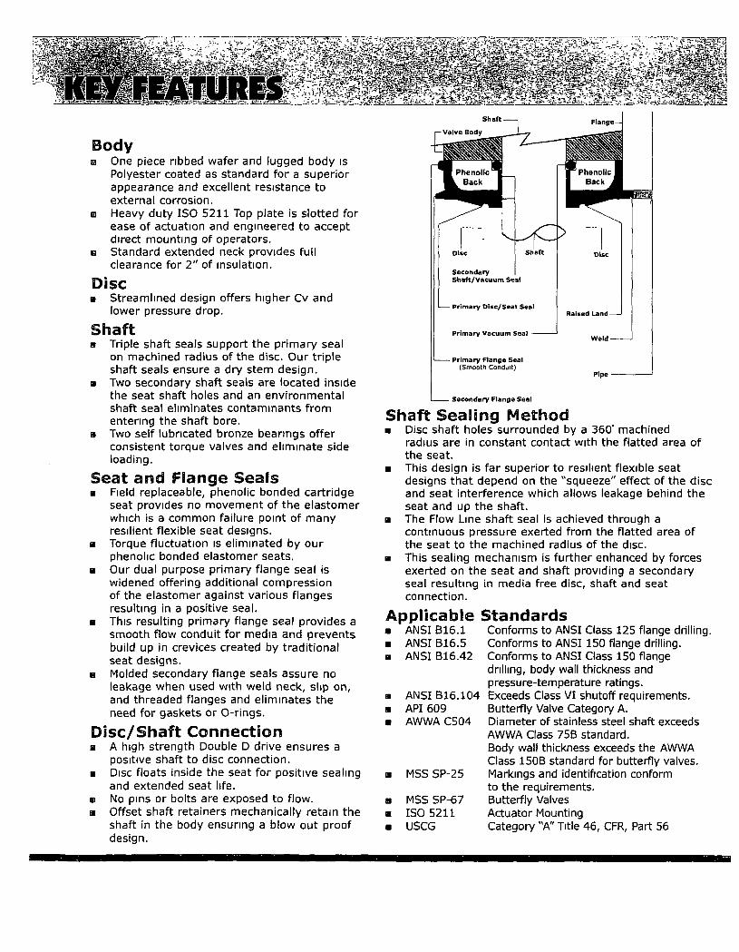


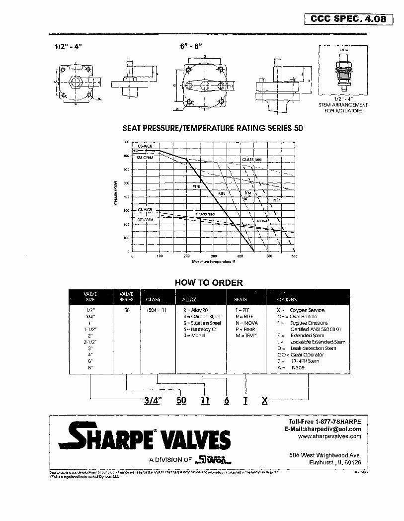


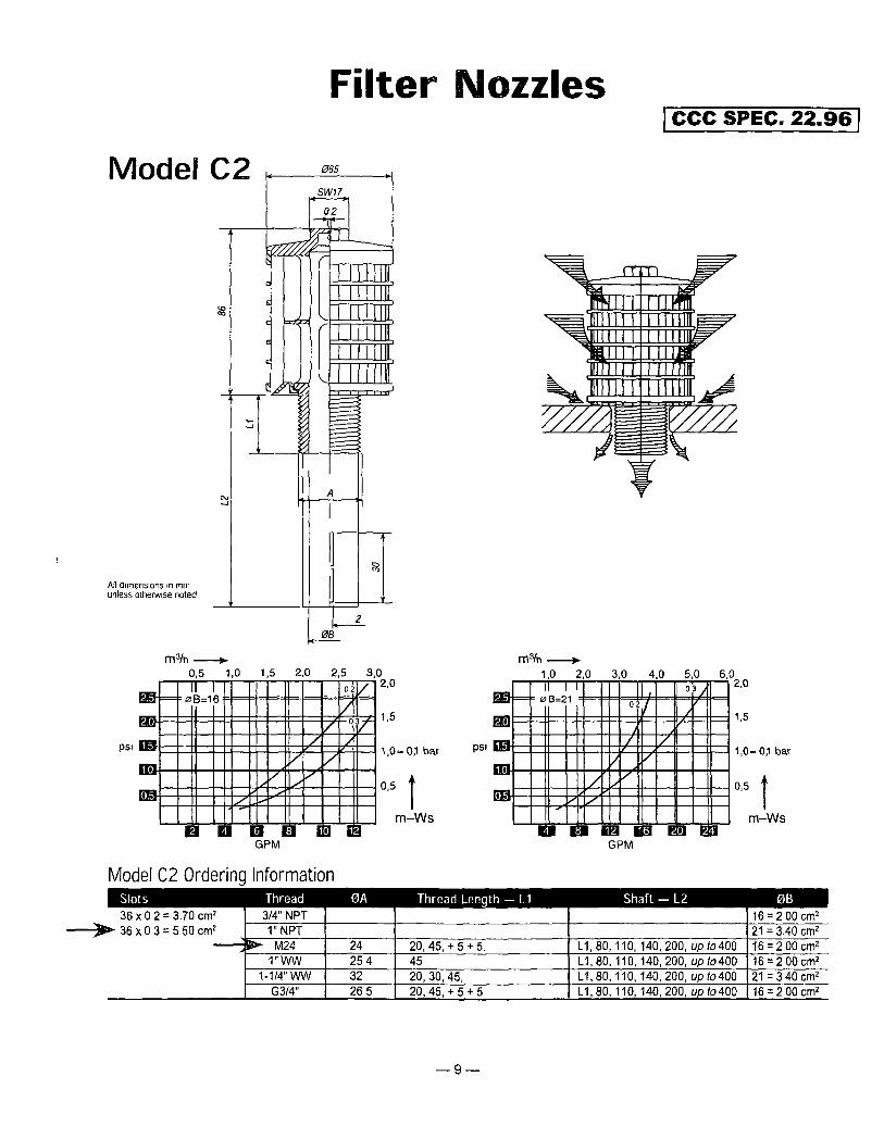


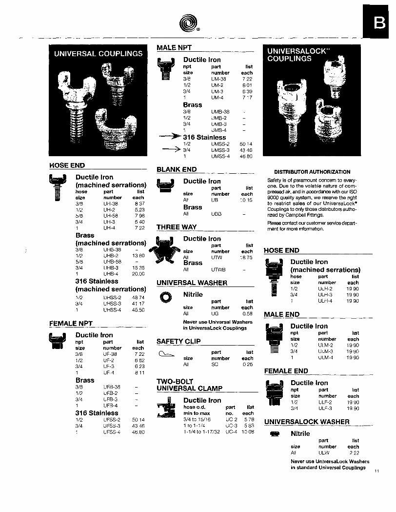
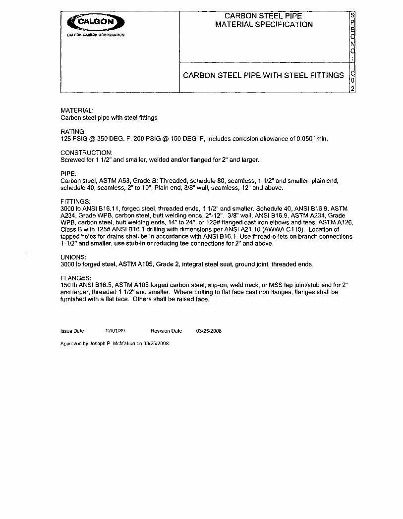
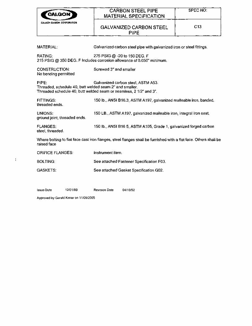


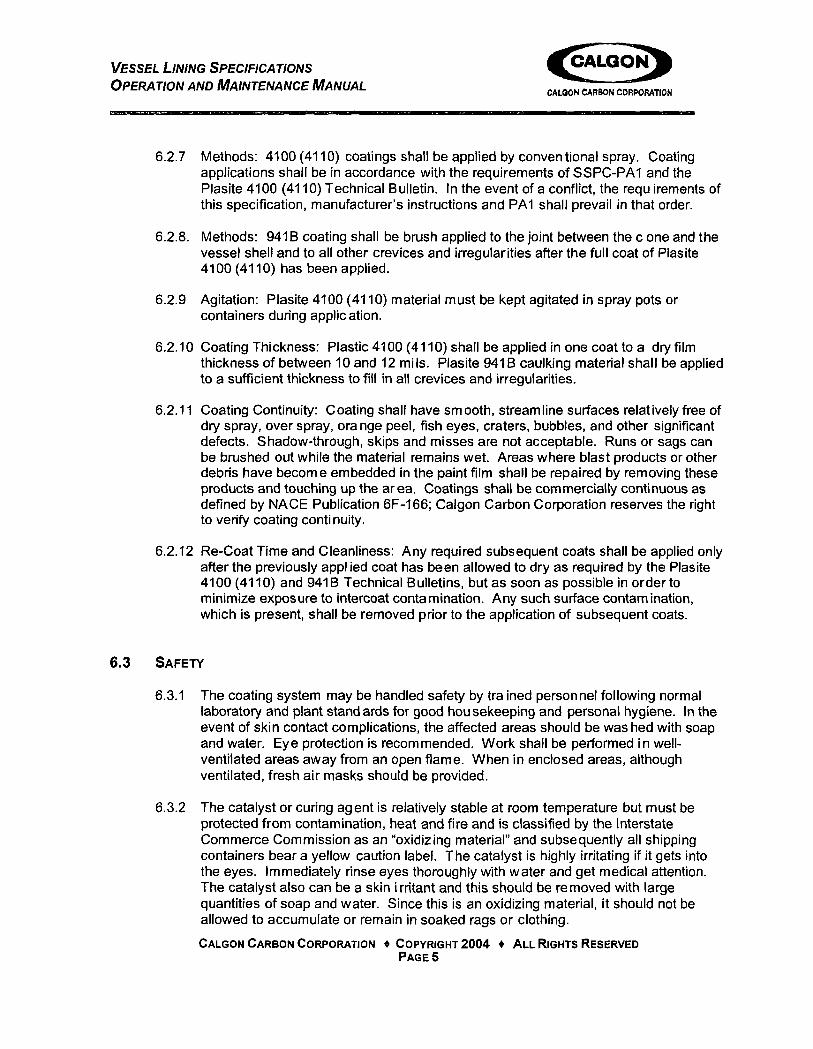


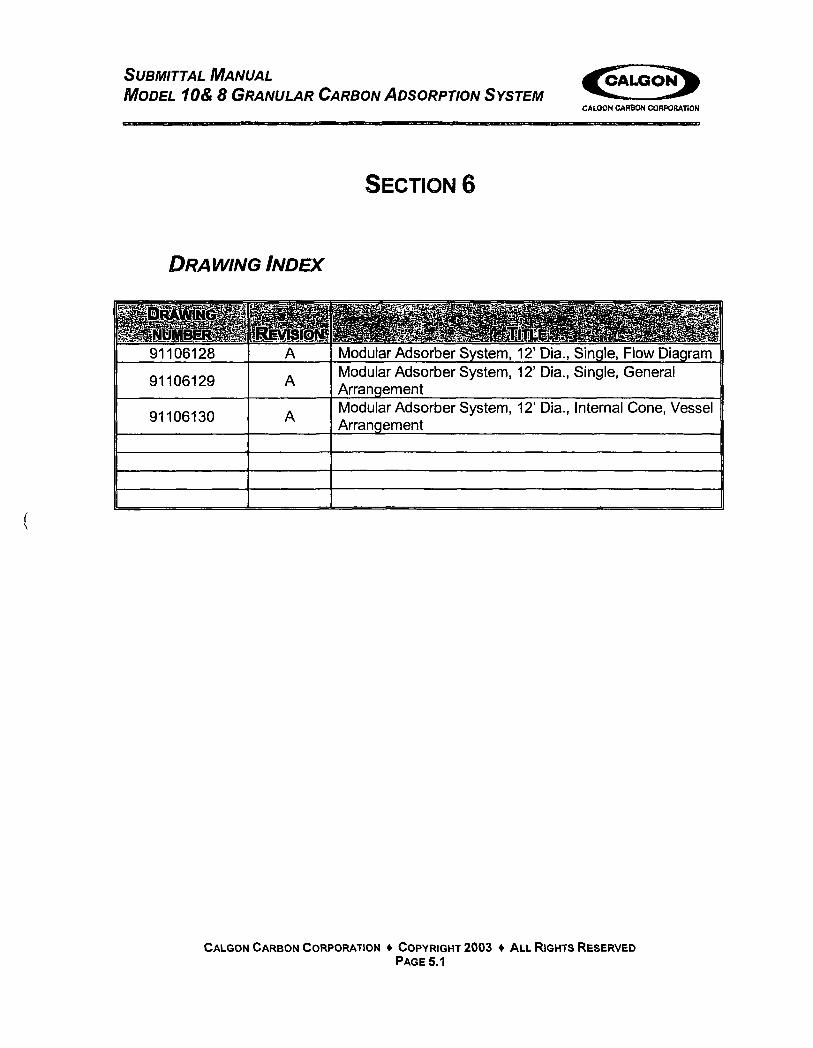


![[*1]Dorothy M. Faison, & c., Appellant, v Tonya …€¦ · [*1]Dorothy M. Faison, & c., Appellant, v Tonya Lewis, & c., et al., Defendants, Bank of America, N.A., Respondent. David](https://static.documents.pub/doc/80x56/5b82edda7f8b9a23668c0845/1dorothy-m-faison-c-appellant-v-tonya-1dorothy-m-faison-c.jpg)


