127
DOT MATRIX PRINTER SP200 SERIES USER’S MANUAL

– 1 –
DOT MATRIX PRINTER
SP200 SERIES
USER’S MANUAL

– 2 –
Federal Communications CommissionRadio Frequency Interference
Statement
This equipment has been tested and found to comply with the limits for a Class A digital device, pursuant to Part 15 of theFCC Rules. These limits are designed to provide reasonable protection against harmful interference when the equipment isoperated in a commercial environment. This equipment generates, uses and can radiate radio frequency energy and, if notinstalled and used in accordance with the instruction manual, may cause harmful interference to radio communications.Operation of this equipment in a residential area is likely to cause harmful interference in which case the user will berequired to correct the interference at his own expense.For compliance with the Federal Noise Interference Standard, this equipment requires a shielded cable.This statement will be applied only for the printers marketed in U.S.A.
Statement ofThe Canadian Department of Communications
Radio Interference Regulations
This digital apparatus does not exceed the Class A limits for radio noise emissions from digital apparatus set out in theRadio Interference Regulations of the Canadian Department of Communications.Le présent appareil numérique n’émet pas de bruits radioélectriques dépassant les limites applicables aux appareils numériques de laclasse A prescrites dans le Règlement sur le brouillage radioélectrique édicté par le ministère des Communications du Canada.The above statement applies only to printers marketed in Canada.
CEManufacturer’s Declaration of Conformity
EC Council Directive 89/336/EEC of 3 May 1989This product has been designed and manufactured in accordance with the International Standards EN 61000-6-3/10.2001and EN 55024/09.98 following the provisions of the Electro Magnetic Compatibility Directive of the European Communi-ties as of May 1989.
EC Council Directive 73/23/EEC and 93/68/EEC of 22 July 1993This product has been designed and manufactured in accordance with the International Standards EN 60950 following theprovisions of the Low Voltage Directive of the European Communities as of July 1993.The above statement applies only to printers marketed in EU.
Trademark acknowledgmentsSP200: Star Micronics Co., Ltd.ESC/POS: Seiko Epson Corporation
Notice• All rights reserved. Reproduction of any part of this manual in any form whatsoever, without STAR’s express permis-
sion is forbidden.• The contents of this manual are subject to change without notice.• All efforts have been made to ensure the accuracy of the contents of this manual at the time of going to press. How-
ever, should any errors be detected, STAR would greatly appreciate being informed of them.• The above notwithstanding, STAR can assume no responsibility for any errors in this manual.
© Copyright 1994 Star Micronics Co., LTD.

– 3 –
Safety Information
Important!Make sure that the printer is turned off and unplugged from the AC outlet and that thecomputer is turned off before making connections.
Important!Do not connect a telephone line into the peripheral drive connector. Failure to observe thismay result in damage to the printer.Also, for safety purposes, do not connect wiring to the external drive connector if there is achance it may carry peripheral voltage.
Connect the ground wire. (EU only)Take out the screw shown in the figure below, then fasten the ground wire terminal to the placewhere the screw was removed and tighten the screw.
Cable
SeparatedGround Wire

– 4 –
Unpacking
Choosing a place for the printerBefore actually unpacking the printer, you should take a few minutes to think about whereyou plan to use it. Remember the following points when doing this.
✓ Choose a firm, level surface where the printer will not be exposed to vibration.✓ The power outlet you plan to connect to for power should be nearby and unobstructed.✓ Make sure that the printer is close enough to your host computer for you to connect the
two.✓ Make sure that the printer is not exposed to direct sunlight.✓ Make sure that the printer is well away from heaters and other sources of extreme heat.✓ Make sure that the surrounding area is clean, dry, and free of dust.✓ Make sure that the printer is connected to a reliable power outlet. It should not be on the
same electric circuit as copiers, refrigerators, or other appliances that cause power spikes.✓ Make sure that the room where you are using the printer is not too humid.
✓ Printer✓ User’s manual✓ Ribbon cartridge✓ Ferrite core (EU only)✓ Fastener (EU only)
Printer
User’s manualRibbon Cartridge
Ferrite core (EU only)
Fastener (EU only)
– 5 –
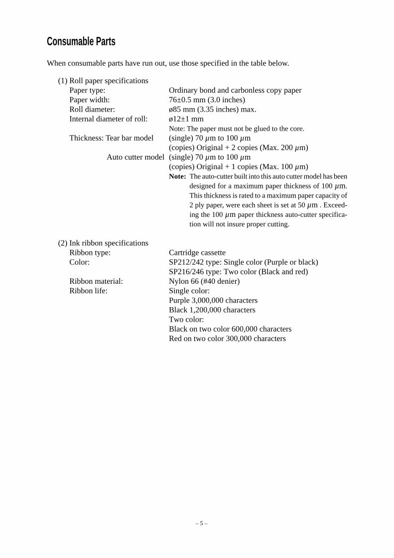
Consumable Parts
When consumable parts have run out, use those specified in the table below.
(1) Roll paper specificationsPaper type: Ordinary bond and carbonless copy paperPaper width: 76±0.5 mm (3.0 inches)Roll diameter: ø85 mm (3.35 inches) max.Internal diameter of roll: ø12±1 mm
Note: The paper must not be glued to the core.Thickness: Tear bar model (single) 70 µm to 100 µm
(copies) Original + 2 copies (Max. 200 µm) Auto cutter model (single) 70 µm to 100 µm
(copies) Original + 1 copies (Max. 100 µm)Note: The auto-cutter built into this auto cutter model has been
designed for a maximum paper thickness of 100 µm.This thickness is rated to a maximum paper capacity of2 ply paper, were each sheet is set at 50 µm . Exceed-ing the 100 µm paper thickness auto-cutter specifica-tion will not insure proper cutting.
(2) Ink ribbon specificationsRibbon type: Cartridge cassetteColor: SP212/242 type: Single color (Purple or black)
SP216/246 type: Two color (Black and red)Ribbon material: Nylon 66 (#40 denier)Ribbon life: Single color:
Purple 3,000,000 charactersBlack 1,200,000 charactersTwo color:Black on two color 600,000 charactersRed on two color 300,000 characters

– 6 –
ON LINEPOWER FEED
3 POWER lamp (Green LED)
4 ON LINE lamp (Green LED)
1 ON LINE switch
2 FEED switch
Control Panel
1ON LINE switchSwitches the printer between ON LINE and OFF LINE.ON LINE and OFF LINE switching is possible onlywhen paper is loaded in the printer.
2 FEED switch• When this switch is pressed and then released within
0.5 sec., the paper feeds on line.• When this switch is held depressed for more than 0.5
sec., the paper feeds continuously.(The above paper feed operation is possible for bothON LINE and OFF LINE modes.)
3 POWER lamp (green LED)• Lights when the power to the printer is on.• Flashes when paper is out, mechanical error occurs, when there is an alarm due to head
temperature detection, or when a CPU error has occurred.• If the paper is out, load new paper and press the ON LINE switch.• When the POWER lamp flashes due to occurrence of a mechanical error, turn off the power and
remove the cause of a mechanical error and then turn on the power again to reset the printer.• If the POWER lamp flashes due to the alarm of the head temperature detection, the printer will
be set automatically when the head temperature becomes low.
4ON LINE lamp (green LED)LED lit: Printer is ON LINELED off: Printer is OFF LINELED flashes: CPU error
When the POWER lamp and ON LINE lamp light simultaneously, a CPU error has occurred.
Loading the Ribbon Cartridge (Tear Bar Model)
1Turn off power to the printer.
2Lift the cover up approx. 3 cm. Hold the covertilted at this angle, then pull it toward you toremove it.
Cover
Power off

– 7 –
3 Place the ribbon cartridge in the direction shownin figure and press it down to load it. If loadingof the ribbon cartridge is not satisfactory, pressdown the cartridge while rotating the ribbon feedknob in the direction of the arrow.
4Turn the ribbon feed knob of the ribbon cartridgein the direction of the arrow to remove slack inthe ribbon.
5Mount the cover by reversing the procedureoutlined in step 2 above.
Note: When removing the ribbon cartridge, raisethe A section and then remove it by holdingthe B section as shown in figure.
Loading the Ribbon Cartridge (Auto Cutter Model)
1Turn off power to the printer.
2Lift the cover up approx. 3 cm. Hold the covertilted at this angle, then pull it toward you toremove it.
Print head
Ink ribbon
Ribbon feedknob
Notchedpart
Ribbon cartridge
A
B
Cover
Power off

– 8 –
4 Place the ribbon cartridge in the direction shownin figure and press it down to load it. If loadingof the ribbon cartridge is not satisfactory, pressdown the cartridge while rotating the ribbon feedknob in the direction of the arrow.
5Turn the ribbon feed knob of the ribbon cartridgein the direction of the arrow to remove slack inthe ribbon.
6Close the Auto Cutter.
7Mount the cover by reversing the procedureoutlined in step 2 above.
Note: When removing the ribbon cartridge, raisethe A section and then remove it by holdingthe B section as shown in figure.
A
B
3Lift up the auto cutter and put it in a verticalposition, as shown in figure.Auto cutter
Print head
Ink ribbon
Auto cutter
Ribbon feedknob
Notched part
Ribboncartridge

– 9 –
Loading the Paper (Tear Bar Model)
1Lift the cover up approx. 3cm. Hold the covertilted at this angle, then pull it toward you toremove it.
2Cut off the front edge of the roll paperperpendicularly.
3Confirm that the power of the printer is turnedon.
4While observing the direction of the roll paper,insert the top end of the paper beneath the paperguide as far as it will go. If the roll paper is installed,the top end of the paper automatically comes outfrom the paper exit.
5Move the paper roll holder in the direction of thearrow, and insert the roll so that the holes in thecore align with the axes of the paper roll holder.Release the paper roll holder to secure the paper.
6 If the paper roll core has not been properlyaligned with the paper roll holder, the covercannot to properly seated until the paper positionis corrected.
7 Press the FEED (paper feed) switch to feed thepaper approximately 10cm.
8 Insert the top edge of the paper into the tear barslot, then mount the cover by reversing theprocedure for removing the cover in step 1above.
Note: When the paper end mark appears on thepaper, replace the roll paper before it runsout.
Cover
FEEDswitch
Roll paper
Core
Axis
Paper roll holder
Roll paper
CoverPositioning rib
Paper roll holder
Tear bar
FEED switch

– 10 –
2Cut off the front edge of the roll paperperpendicularly.
3Confirm that the power of the printer is turnedon.
4While observing the direction of the roll paper,insert the top end of the paper beneath the paperguide as far as it will go. If the roll paper is installed,the top end of the paper automatically comes outfrom the paper exit. After 2cm of paper are fedout, the paper is automatically cut off.
5Move the paper roll holder in the direction of thearrow, and insert the roll so that the holes in thecore align with the axes of the paper roll holder.Release the paper roll holder to secure the paper.
6 If the paper roll core has not been properlyaligned with the paper roll holder, the covercannot to properly seated until the paper positionis corrected.
7 Press the FEED (paper feed) switch to feed thepaper approximately 10cm.
Loading the Paper (Auto Cutter Model)
1Lift the cover up approx. 3cm. Hold the covertilted at this angle, then pull it toward you toremove it.
Cover
FEEDswitch
Roll paper
Core
Axis
Paper roll holder
Roll paper
CoverPositioning rib
Paper roll holder

– 11 –
9 Pull on the edge of the paper to remove any slackand then lower the auto cutter.
0 Insert the paper through the paper outlet and thenreplace the cover by reversing the removal steps.
Note: When the paper end mark appears on thepaper, replace the roll paper before it runsout.
8 Insert the tip of the roll paper in the auto cutterpaper slit.
• When using copying paper, insert only the original(the upper paper) into the slit of the auto cutter.Insert the paper which is to be copied (the lowerpaper) between the platen and the auto cutter.
Auto cutterPaperinsertionslit
Upper paper
FEED switch
Print head
Paper insertionslit
Platen
Lower paper Print head Platen
Lower paper
Upper paper
Auto cutter
Paper outlet
Auto cutter
Paper insertionslit

– 12 –
81
Dip Switch Settings - Parallel Interface Type
DIP-SWSwitch Function ON OFF
1 Paper out detection Valid Invalid
2 Control code CR Invalid Valid
3
4 International character set See below
5
6 Data bufferAvailable Unavailable(approx. 1k byte) (1 line)
7Character generation setting See below
8
The factory settings of DIP switch are all on.
International character setSwitch U.S.A. France Germany England Denmark Sweden Italy Spain
3 ON OFF ON OFF ON OFF ON OFF
4 ON ON OFF OFF ON ON OFF OFF
5 ON ON ON ON OFF OFF OFF OFF
Character generationSwitch US EC JP JP
7 ON ON OFF OFF
8 ON OFF ON OFF
ON
OFF
– 13 –
101
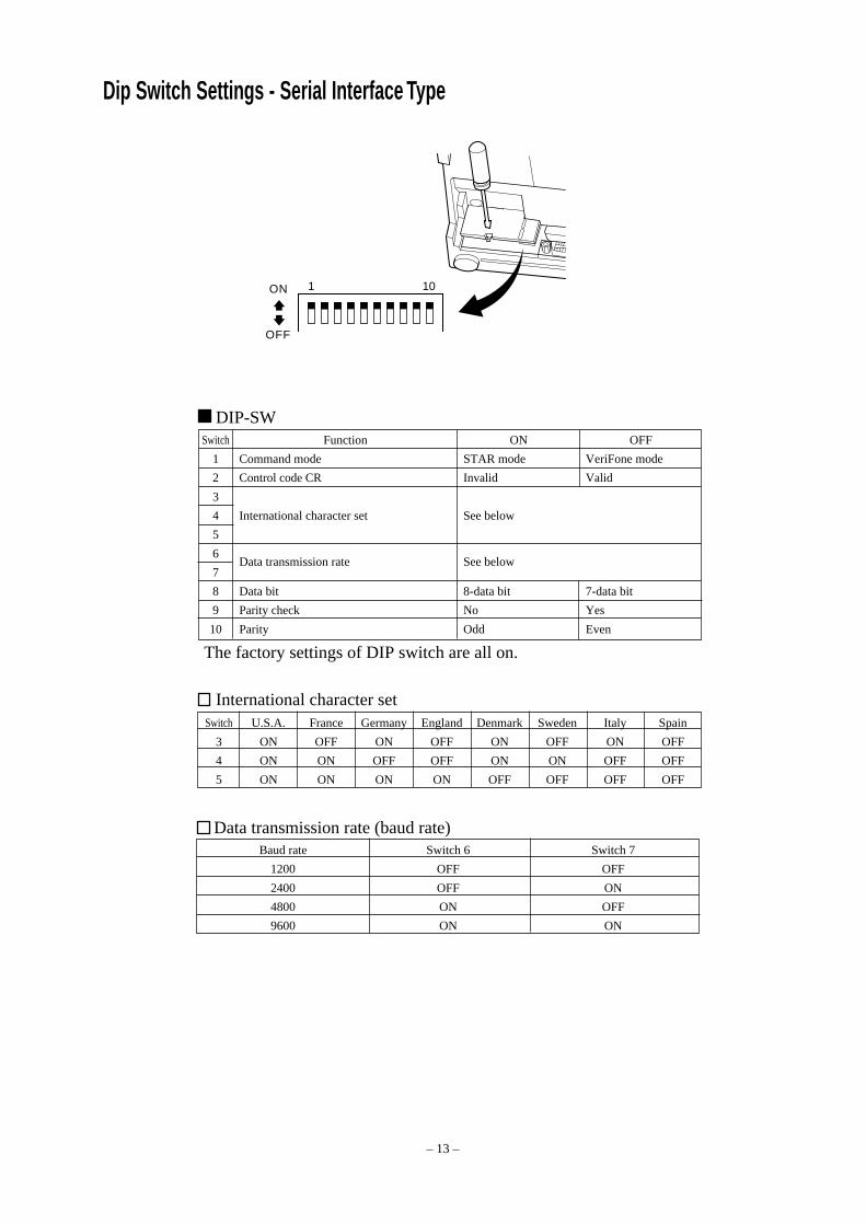
Dip Switch Settings - Serial Interface Type
DIP-SWSwitch Function ON OFF
1 Command mode STAR mode VeriFone mode
2 Control code CR Invalid Valid
3
4 International character set See below
5
6Data transmission rate See below
7
8 Data bit 8-data bit 7-data bit
9 Parity check No Yes
10 Parity Odd Even
The factory settings of DIP switch are all on.
International character setSwitch U.S.A. France Germany England Denmark Sweden Italy Spain
3 ON OFF ON OFF ON OFF ON OFF
4 ON ON OFF OFF ON ON OFF OFF
5 ON ON ON ON OFF OFF OFF OFF
Data transmission rate (baud rate)Baud rate Switch 6 Switch 7
1200 OFF OFF
2400 OFF ON
4800 ON OFF
9600 ON ON
ON
OFF

– 14 –
Printing method Serial impact dot matrix printingNumber of columns 42 (16 cpi)
35 (13.4 cpi)Printing direction Bi-directional with friction feedPrinting width Max. 66 mmDot spacing 0.316(H) × 0.423(V) mmCharacter size 1.28W × 2.87H mm (7×7, 16 cpi)
1.59W × 2.87H mm (9×7, 13.4 cpi)Character set Alphanumeric characters: 95
International characters: 12Special characters: 64IBM special characters: 83
Print speed Approx. 2.5 lines/secPaper feed speed Approx. 9 lines/secLine spacing 1/6 inchCharacter structure 7×7 or 9×7Interface RS232C / Centronics compatibleReceived buffer size Approx. 1K bytePrinter Reliability 9 million lines Calculated Real Time MCBF
2.5 million lines MCBFPrint head life 75 million charactersCutter life 0.3 million cutting (Full or Partial Cut)Temperature Operating: 0 to 50 °C
Storage: -20 to 70 °CHumidity Operating: 10 to 90% RH (without condensation)
Storage: 5 to 95% RH (without condensation)Dimension Tear bar model: 158 × 234 × 193 (W×D×H mm)
Auto cutter model: 158 × 239.7 × 193 (W×D×H mm)Weight Tear bar model: Approx. 3 Kg
Auto cutter model: Approx. 3.4 Kg
Specifications
Please access the following URLhttp://www.star-micronics.co.jp/service/frame_sp_spr_e.htmfor the lastest printer drivers and utilities.

– 1 –
IMPRIMANTE MATRICIELLE
SÉRIE SP200
MODE D’EMPLOI

– 2 –
Federal Communications CommissionInterférences radioélectriques
Déclaration
Cet appareil a été testé et déclaré conforme aux normes des appareils numériques de Classe A, conformément à l’article 15du règlement de la FCC. Ces normes ont été établies en vue de fournir une protection convenable contre les parasites enusage commercial. Cet appareil génère, utilise et peut émettre des ondes radioélectriques, et s’il n’est pas installé et utiliséconformément aux instructions, peut produire des parasites en communications radio. L’utilisation de cet appareil dans unezone résidentielle produira vraisemblablement des parasites, dont l’élimination devra être prise en charge par l’utilisateurlui-même et à ses frais.Pour être conforme à la norme antiparasitage fédérale, cet appareil doit être utilisé avec un câble blindé.Cette déclaration ne concerne que les imprimantes vendues aux États-Unis d’Amérique.
Déclaration duMinistère des Communications du CanadaRèglement sur le brouillage radioélectrique
Le présent appareil numérique n’émet pas de bruits radioélectriques dépassant les limites applicables aux appareilsnumériques de la Classe A prescrites dans le Règlement sur le brouillage radioélectrique édicté par le Ministère desCommunications du Canada.Cette déclaration ne concerne que les imprimantes vendues au Canada.
Déclaration de conformité CE du fabricant
Directive du conseil de la CE 89/336/EEC du 3 mai 1989Ce produit a été conçu et fabriqué en accord avec les normes internationales EN 61000-6-3/10.2001 et EN 55024/09.98selon les dispositions de la Directive de mai 1989 de la CE, relative à la compatibilité électromagnétique.
Directives du conseil de la CE 73/23/EEC et 93/68/EEC du 22 juillet 1993Ce produit a été conçu et fabriqué en accord avec les normes internationales EN 60950 selon les dispositions de la Directivede juillet 1993 de la CE, relative à la basse tension.Valable pour les imprimantes commercialisées en Europe seulement.
Renseignements sur les marques de fabriqueSP200: Star Micronics Co., Ltd.ESC/POS: Seiko Epson Corporation
Remarque• Tous droits réservés. La reproduction d’une partie de ce manuel sous quelque forme que ce soit, sans la permission
expresse de STAR, est strictement interdite.• Le contenu de ce manuel peut être modifié sans préavis.• Des précautions ont été prises lors de l’impression de ce manuel pour garantir la précision de son contenu. Cependant,
en cas d’erreur dans ce manuel, STAR apprécierait grandement d’en être informé.• Cependant, STAR n’assume aucune responsabilité en cas d’erreurs dans ce manuel.
© Copyright 1994 Star Micronics Co., LTD.

– 3 –
Informations concernant la sécurité
Attention!Assurez-vous que l’imprimante est hors tension, qu’elle est débranchée de la prise secteuret que l’ordinateur est hors tension avant d’effectuer les connexions.
Attention!Ne connectez pas une ligne de téléphone à la borne du pilote de périphérique, sous peine derisquer d’endommager l’imprimante.Pour des raisons de sécurité, il convient également de ne pas brancher d’appareil périphériqueen cas de risque de survoltage.
Attachez le fil de mise à la terre. (UE seulement)Déposez la vis indiquée dans le schéma ci-dessous, puis attachez la borne du fil de mise à la terreà l’endroit occupé précédemment par la vis et resserrez la vis.
Câble
Fil de masse séparé

– 4 –
Emplacement de l’imprimanteAvant de déballer l’imprimante, déterminez l’emplacement où vous souhaitez l’installer.Veuillez observer les points ci-dessous lors de votre choix.
✓ Choisissez une surface stable et de niveau sur laquelle l’imprimante ne sera exposée àaucune vibration.
✓ Assurez-vous que l’emplacement dispose d’une prise secteur proche et d’accès aisé.✓ Assurez-vous que la distance entre l’imprimante et l’ordinateur-hôte vous permet de les
raccorder aisément.✓ Assurez-vous que l’imprimante n’est pas exposée directement aux rayons du soleil.✓ Tenez l’imprimante à l’écart des sources de chaleur importante, telles que les appareils de
chauffage, etc.✓ Assurez-vous que le lieu où vous souhaitez installer l'imprimante est propre, sec et n'est
pas poussiéreux.✓ Assurez-vous que la prise secteur à laquelle vous raccordez l’imprimante délivre une
tension stable. Evitez de raccorder l’imprimante à la prise secteur d’un circuit alimentantde gros consommateurs de courant, tels qu’un photocopieur, réfrigérateur, etc.
✓ Assurez-vous que le lieu où vous installez l’imprimante n’est pas excessivement humide.
Déballage✓ Imprimante✓ Mode d’emploi✓ Cartouche à ruban✓ Tore de ferrite (UE seulement)✓ Attache (UE seulement)
Imprimante
Mode d’emploiCartouche à ruban
Tore de ferrite (UE seulement)
Attache (UE seulement)

– 5 –
Consommables
Lorsque les consommables sont épuisés, utilisez ceux qui sont spécifiés dans le tableau ci-dessous.
(1) Rouleau de papier, caractéristiquesPapier ordinaire: Papier de copie bond et sans carbone ordinaireLargeur de papier: 76 ±0,5 mm (3,0 pouces)Diamètre du rouleau: ø85 mm (3,35 pouces) max.Diamètre intérieur du rouleau: ø12±1 mmRemarque : Il ne faut pas que le papier soit collé au noyau du rouleau.Epaisseur: Modèle à plaque-couteau (simple) 70 µm à 100 µm
(copies) Original + 2 copies (200 µm max.) Modèle à coupe-papier automatique (simple) 70 µm à 100 µm
(copies) Original + 1 copie (100 µm max.)Remarque :Le coupe-papier automatique de ce modèle a
été conçu pour une épaisseur de papier maxi-mum de 100 µm. Cette épaisseur est calculéepour une capacité de papier maximale depapier à 2 jets, dont chaque feuille est réglée à50 µm. La coupe ne sera pas correcte si vousutilisez du papier dépassant les spécificationsde 100 µm d’épaisseur pour le papier ducoupe-papier automatique.
(2) Ruban encreur, caractéristiquesType de ruban: Cassette à cartoucheCouleur: Type SP212/242 : Monochrome (violet ou noir)
Type SP216/246 : Deux couleurs (noir et rouge)Matériau du ruban: Nylon 66 (denier #40)Durée de service du ruban: Monochrome:
Violet 3 000 000 caractèresNoir 1 200 000 caractèresDeux couleurs:Noir sur deux couleurs 600 000 caractèresRouge sur deux couleurs 300 000 caractères

– 6 –
Panneau de Commande
1 Touche ON LINECette touche permet de mettre l’imprimante enligne ou hors ligne. Vous ne pouvez effectuercette commutation que si du papier est chargédans l’imprimante.
2 Touche d’avance FEED• Si vous appuyez sur cette touche, puis la relâchez
moins de 0,5 seconde après, le papier avancerad’une ligne à la fois.
• Si vous maintenez la pression sur cette touchependant plus de 0,5 seconde, le papier avancera defaçon continue. (Cela est valable que l’imprimantesoit en ligne ou hors ligne.)
3 Témoin d’alimentation POWER (DEL verte)• Ce témoin s’allume quand l’imprimante est sous tension.• Ce témoin clignote quand il n’y a plus de papier dans l’imprimante, quand une erreur mécanique
ou une surchauffe de la tête d’impression est détectée, ou quand une erreur s’est produite au niveaude l’unité centrale de traitement.
• Si le papier est épuisé, mettez en place un nouveau rouleau, puis appuyez sur la touche ON LINE.• Si le témoin POWER clignote en raison d’une erreur mécanique, mettez l’imprimante hors
tension, puis éliminez la cause de l’erreur mécanique et remettez l’imprimante sous tension pourla réinitialiser.
• Si le témoin POWER clignote après avoir détecté une surchauffe de la tête d’impression,l’imprimante sera réinitialisée automatiquement quand la température de la tête d’impressionaura baissé.
4 Témoin ON LINE (DEL verte)DEL allumée : L’imprimante est en ligneDEL éteinte : L’imprimante est hors ligneDEL clignotante : Erreur de l’unité centrale
Quand les témoins POWER et ON LINE s’allument simultanément, une erreur s’est produite auniveau de l’unité centrale de traitement.
Installation d’une cartouche à ruban (Modèle avec barre de découpage)
1 Mettez l’imprimante hors tension.
2 Soulevez le capot d’environ 3 cm. Tout en tenantle couvercle incliné à cet angle, tirez-le vers vouspour l’enlever.
Capot
Hors tension
ON LINEPOWER FEED
3
4
1
2
Touche ON LINE
Touche d’avance FEED
Témoin d’alimentation POWER (DEL verte)
Témoin ON LINE (DEL verte)
– 7 –
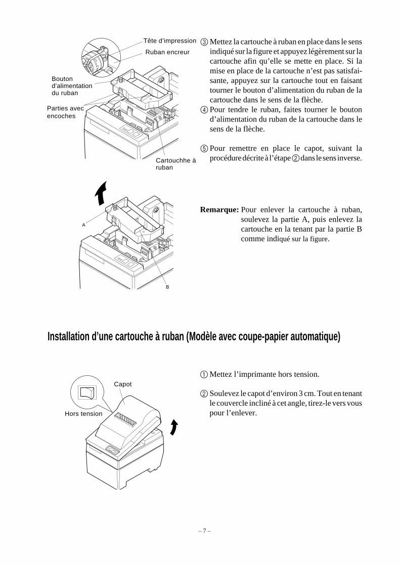
3 Mettez la cartouche à ruban en place dans le sensindiqué sur la figure et appuyez légèrement sur lacartouche afin qu’elle se mette en place. Si lamise en place de la cartouche n’est pas satisfai-sante, appuyez sur la cartouche tout en faisanttourner le bouton d’alimentation du ruban de lacartouche dans le sens de la flèche.
4 Pour tendre le ruban, faites tourner le boutond’alimentation du ruban de la cartouche dans lesens de la flèche.
5 Pour remettre en place le capot, suivant laprocédure décrite à l’étape 2 dans le sens inverse.
Remarque: Pour enlever la cartouche à ruban,soulevez la partie A, puis enlevez lacartouche en la tenant par la partie Bcomme indiqué sur la figure.
Installation d’une cartouche à ruban (Modèle avec coupe-papier automatique)
1 Mettez l’imprimante hors tension.
2 Soulevez le capot d’environ 3 cm. Tout en tenantle couvercle incliné à cet angle, tirez-le vers vouspour l’enlever.
Tête d’impression
Ruban encreur
Boutond’alimentationdu ruban
Parties avecencoches
Cartouchhe àruban
A
B
Capot
Hors tension

– 8 –
4 Mettez la cartouche à ruban en place dans le sensindiqué sur la figure et appuyez légère-ment surla cartouche afin qu’elle se mette en place. Si lamise en place de la cartouche n’est pas satisfai-sante, appuyez sur la cartouche tout en faisanttourner le bouton d’alimentation du ruban de lacartouche dans le sens de la flèche.
5 Pour tendre le ruban, faites tourner le boutond’alimentation du ruban de la cartouche dans lesens de la flèche.
6 Refermez l’unité de découpage automatique.
7 Pour remettre en place le capot, suivez laprocédure décrite à l’étape 2 dans le sens inverse.
Remarque: Pour enlever la cartouche à ruban,soulevez la partie A, puis enlevezla cartouche en la tenant par lapartie B comme indiqué sur lafigure.
A
B
3 Soulevez l’unité de découpage automatique pourla mettre en position verticale, comme indiquésur la figur.
Unité de découpageautomatique
Tête d’impressionRuban encreur
Boutond’alimentationdu ruban
Parties avecencoches
Cartouchhe àruban
Unité de découpageautomatique
– 9 –
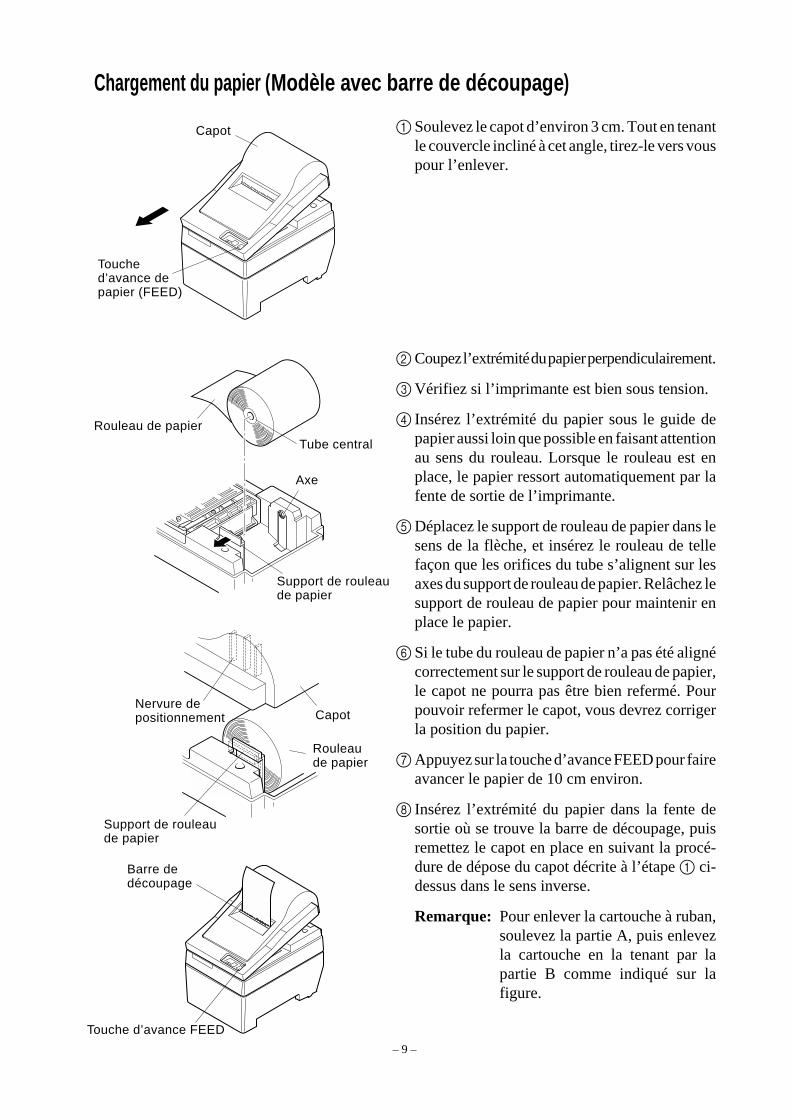
Chargement du papier (Modèle avec barre de découpage)
1 Soulevez le capot d’environ 3 cm. Tout en tenantle couvercle incliné à cet angle, tirez-le vers vouspour l’enlever.
2 Coupez l’extrémité du papier perpendiculairement.
3 Vérifiez si l’imprimante est bien sous tension.
4 Insérez l’extrémité du papier sous le guide depapier aussi loin que possible en faisant attentionau sens du rouleau. Lorsque le rouleau est enplace, le papier ressort automatiquement par lafente de sortie de l’imprimante.
5 Déplacez le support de rouleau de papier dans lesens de la flèche, et insérez le rouleau de tellefaçon que les orifices du tube s’alignent sur lesaxes du support de rouleau de papier. Relâchez lesupport de rouleau de papier pour maintenir enplace le papier.
6 Si le tube du rouleau de papier n’a pas été alignécorrectement sur le support de rouleau de papier,le capot ne pourra pas être bien refermé. Pourpouvoir refermer le capot, vous devrez corrigerla position du papier.
7 Appuyez sur la touche d’avance FEED pour faireavancer le papier de 10 cm environ.
8 Insérez l’extrémité du papier dans la fente desortie où se trouve la barre de découpage, puisremettez le capot en place en suivant la procé-dure de dépose du capot décrite à l’étape 1 ci-dessus dans le sens inverse.
Remarque: Pour enlever la cartouche à ruban,soulevez la partie A, puis enlevezla cartouche en la tenant par lapartie B comme indiqué sur lafigure.
Capot
Touched’avance depapier (FEED)
Rouleau de papier
Tube central
Axe
Support de rouleaude papier
Rouleaude papier
CapotNervure depositionnement
Support de rouleaude papier
Barre dedécoupage
Touche d’avance FEED

– 10 –
2 Coupez l’extrémité du papier perpendiculaire-ment.
3 Vérifiez si l’imprimante est bien sous tension.4 Insérez l’extrémité du papier sous le guide de
papier aussi loin que possible en faisant attentionau sens du rouleau. Lorsque le rouleau est enplace, le papier ressort automatiquement par lafente de sortie de l’imprimante. Après la sortie de2 cm de papier, le papier est automatiquementcoupé.
5 Déplacez le support de rouleau de papier dans lesens de la flèche, et insérez le rouleau de tellefaçon que les orifices du tube s’alignent sur lesaxes du support de rouleau de papier. Relâchez lesupport de rouleau de papier pour maintenir enplace le papier.
6 Si le tube du rouleau de papier n’a pas été alignécorrectement sur le support de rouleau de papier,le capot ne pourra pas être bien refermé. Pourpouvoir refermer le capot, vous devrez corriger laposition du papier.
7 Appuyez sur la touche d’avance FEED pour faireavancer le papier de 10 cm environ.
Chargement du papier (Modèle avec coupe-papier automatique)
1 Soulevez le capot d’environ 3 cm. Tout en tenantle couvercle incliné à cet angle, tirez-le vers vouspour l’enlever.
Support de rouleaude papier
Capot
Touched’avance depapier (FEED)
Rouleau de papier
Tube central
Axe
Rouleaude papier
CapotNervure depositionnement
Support de rouleaude papier

– 11 –
9 Tirez sur l’extrémité du papier afin de tendre lepapier, puis rabaissez l’unité de découpageautomatique.
0 Insérez le papier dans la sortie de papier, puisremettez le capot en place en suivant la procé-dure de dépose du capot dans le sens inverse.
Remarque: Quand le repère de fin de papierapparaît sur le papier, remplacez lerouleau de papier avant qu’il soitterminé.
8 Insérez l’extrémité du papier dans la fente del’unité de découpage automatique.
• Quand vous utilisez du papier pour copie, insérezseulement l’original (feuille supérieure) dans lafente de l’unité de découpage automatique.Insérez le papier de copie (feuille inférieure)entre le cylindre et l’unité de découpageautomatique.
Unité dedécoupageautomatiqueFente
d’insertiondu papier
Feuillesupérieures
Têted’impression
Fented’insertion dupapier
Cylindre
Feuille inférieure Têted’impression
Cylindre
Feuille inférieure
Feuille supérieures
Unité de découpageautomatique
Sortie depapier
Unité dedécoupageautomatique
Fente d’insertiondu papier
Touche d’avance FEED

– 12 –
81
Commutateurs DIPCommutateur Fonction ACTIVÉ DÉSACTIVÉ
1 Détection de sortie du papier Valide Invalide
2 Code de commande CR Invalide Valide
3
4 Jeu de caractères internationaux Voir ci-dessous.
5
6 Mémoire tamponDisponible Non disponible(environ 1 koctet) (1 ligne)
7Réglage de génération de caractères Voir ci-dessous.
8
Tous les réglages de commutateur DIP sont activés au départ de l’usine.
Jeu de caractères internationauxCommutateur E-U France Allemagne Angleterre Danemark Suède Italie Espagne
3 ACTIVÉ DÉSACTIVÉ ACTIVÉ DÉSACTIVÉ ACTIVÉ DÉSACTIVÉ ACTIVÉ DÉSACTIVÉ
4 ACTIVÉ ACTIVÉ DÉSACTIVÉ DÉSACTIVÉ ACTIVÉ ACTIVÉ DÉSACTIVÉ DÉSACTIVÉ
5 ACTIVÉ ACTIVÉ ACTIVÉ ACTIVÉ DÉSACTIVÉ DÉSACTIVÉ DÉSACTIVÉ DÉSACTIVÉ
Génération de caractèresCommutateur US EC JP JP
7 ACTIVÉ ACTIVÉ DÉSACTIVÉ DÉSACTIVÉ
8 ACTIVÉ DÉSACTIVÉ ACTIVÉ DÉSACTIVÉ
Affectation des broches des commutateurs DIP – Type à interface parallèle
ACTIVÉ
DÉSACTIVÉ

– 13 –
101
Affectation des broches des commutateurs DIP – Type à interface sèrie
Débit en baudsDébit en bauds Commutateur 6 Commutateur 7
1200 DÉSACTIVÉ DÉSACTIVÉ
2400 DÉSACTIVÉ ACTIVÉ
4800 ACTIVÉ DÉSACTIVÉ
9600 ACTIVÉ ACTIVÉ
Commutateurs DIPCommutateur Fonction ACTIVÉ DÉSACTIVÉ
1 Mode de commande Mode STAR Mode VeriFone
2 Code de commande CR Invalide Valide
3
4 Jeu de caractères internationaux Voir ci-dessous.
5
6Débit en bauds Voir ci-dessous.
7
8 Longueur des données 8 bits 7 bits
9 Contrôle de parité Désactivé Activé
10 Parité Impair Pair
Tous les réglages de commutateur DIP sont activés au départ de l’usine.
Jeu de caractères internationauxCommutateur E-U France Allemagne Angleterre Danemark Suède Italie Espagne
3 ACTIVÉ DÉSACTIVÉ ACTIVÉ DÉSACTIVÉ ACTIVÉ DÉSACTIVÉ ACTIVÉ DÉSACTIVÉ
4 ACTIVÉ ACTIVÉ DÉSACTIVÉ DÉSACTIVÉ ACTIVÉ ACTIVÉ DÉSACTIVÉ DÉSACTIVÉ
5 ACTIVÉ ACTIVÉ ACTIVÉ ACTIVÉ DÉSACTIVÉ DÉSACTIVÉ DÉSACTIVÉ DÉSACTIVÉ
ACTIVÉ
DÉSACTIVÉ

– 14 –
Méthode d’impression Impression par matrice de points série à impactNombre de colonnes 42 (16 cpp)
35 (13,4 cpp)Direction d’impression Bidirectionnelle avec entraînement par frictionLargeur de la ligne d’impression 66 mm maxEspacement des points 0,316 (H) × 0,423 (V) mmTaille de caractère 1,28 L × 2,87 H mm (7 × 7, 16 cpp)
1,59 L × 2,87 H mm (9 × 7, 13,4 cpp)Jeu de caractères Caractères alphanumériques : 95
Caractères internationaux : 12Caractères spéciaux : 64Caractères IBM spéciaux : 83
Vitesse d’impression Environ 2,5 lignes/secondeVitesse d’avance du papier Environ 9 lignes/secondeInterligne 1/6 pouceStructure des caractères 7×7 ou 9×7Interface Compatible RS-232C/CentronicsTaille de mémoire tampon réceptrice Environ 1 koctetFiabilité 9 millions de lignes temps réel calculé MCBF
2,5 millions de lignes MCBFDurée de service de la tête d’impression 75 millions de caractèresDurée de service du massicot 0,3 million de coupes (coupe totale ou partielle)Température Fonctionnement: 0 à 50°C
Stockage: -20 à 70°CHumidité Fonctionnement: 10 à 90% HR (sans condensation)
Stockage: 5 à 95% HR (sans condensation)Dimensions Modèle à plaque-couteau: 158 × 234 × 193 (L×P×H mm)
Modèle à coupe-papier automatique: 158 × 239.7 × 193 (L×P×H mm)Poids Modèle à plaque-couteau: Environ 3 Kg
Modèle à coupe-papier automatique: Environ 3,4 Kg
Caractéristiques
Pour obtenir les informations les plus récentes au sujet des pilotes et des logiciels utilitaires,veuillez consulter l’adresse URL http:/www.star-micronics.co.jp/service/frame_sp_spr_e.htm.

– 1 –
NADELDRUCKER
BAUREIHE SP200
BEDIENUNGSANLEITUNG

– 2 –
Federal Communications CommissionErklärung zur elektromagnetischen Störungssicherheit
Dieses Gerät wurde typengeprüft und entspricht den Vorschriften nach Klasse A für digitale Geräte, Teil 15 der US-amerikanischen FCC-Vorschrift. Diese Störgrenzen sollen ausreichenden Schutz gegen elektromagnetische Störungen beiBetrieb in gewerblichen Umgebungen bieten. Das Gerät erzeugt, arbeitet mit und verbreitet elektromagnetische Wellen undkann bei unsachgemäßem Betrieb Störungen im Funkverkehr verursachen.Bei Betrieb dieses Geräts in Wohngebieten können elektromagnetische Störungen verursacht werden, die der Anwender aufeigene Kosten korrigieren muss.Zur Erfüllung der US-amerikanischen Vorschriften zur Störungssicherheit ist für dieses Gerät ein abgeschirmtes Kabelerforderlich.Diese Erklärung gilt nur für Drucker, die in den USA vermarktet werden.
Erklärung der kanadischen KommunikationsbehördeRichtlinien zur Störungssicherheit
Dieses digitale Gerät überschreitet nicht die Grenzen der Klasse A für Funkstörungen von Digitalgeräten, wie in den Richtlinienzur Funkstörungssicherheit der kanadischen Kommunikationsbehörde festgelegt.Die obige Erklärung gilt nur für Drucker, die in Kanada vermarktet werden.
CEKonformitätserklärung des Herstellers
Direktive des EG-Rats 89/336/EEC vom 3. Mai 1989Dieses Produkt, konstruiert und hergestellt entsprechend den internationalen Normen EN 61000-6-3/10.2001 und EN 55024/09.98 entspricht den Vorschriften der Direktive für elektromagnetische Verträglichkeit der Europäischen Gemeinschaft,Stand Mai 1989.
Direktive des EG-Rats 73/23/EEC und 93/68/EEC vom 22. Juni 1993Dieses Produkt, konstruiert und hergestellt entsprechend den internationalen Normen EN 60950 entspricht den Vorschriften derDirektive für Niederspannungen der Europäischen Gemeinschaft, Stand Juli 1993.Die obigen Feststellungen gelten für Drucker, die in der EU vertrieben werden.
Eingetragene WarenzeichenSP200: Star Micronics Co., Ltd.ESC/POS: Seiko Epson Corporation
Hinweis• Alle Rechte vorbehalten. Kein Teil dieses Handbuches darf in irgendeiner Form ohne ausdrückliche Genehmigung der
Firma STAR reproduziert werden.• Änderungen jederzeit ohne Angabe von Gründen möglich.• Bei der Zusammenstellung von Texten und Abbildungen wurde mit größter Sorgfalt vorgegangen. Trotzdem können
Fehler nicht vollständig ausgeschlossen werden. Für Hinweise auf eventuell vorgefundene Fehler ist der Herausgeberdankbar.
• Die Firma STAR kann keine Verantwortung für Fehler in diesem Handbuch und eventuell daraus entstehende Folgenverantwortlich gemacht werden.
© Copyright 1994 Star Micronics Co., LTD.

– 3 –
Sicherheitsinformation
Wichtig!Vor dem Anschließen der Kabel sicherstellen, daß der Drucker ausgeschaltet und vom Netzgetrennt ist.
Wichtig!Nicht eine Telefonleitung an die Peripheriebuchse anschließen. Wenn dies geschieht, bestehtdie Gefahr von Schäden am Drucker. Aus Sicherheitsgründen außerdem nicht Verdrahtungan die Peripheriebuchse anschließen, wenn die Möglichkeit besteht, daß zu starke Spannunganliegt.
Den Erdungsdraht anschließen. (nur EU)Die Schraube herausnehmen, wie in der Abbildung unten gezeigt, und dann die Erdungsdraht-klemme an der Stelle befestigen, wo die Schraube entfernt wurde, und die Schraube erneutbefestigen.
Kabel
Getrennt Massedraht

– 4 –
Auspacken✓ Drucker✓ Bedienungsanleitung✓ Farbbandkassette✓ Ferritkern (nur EU)✓ Befestigungsband (nur EU)
Drucker
BedienungsanleitungFarbbandkassette
Ferritkern (nur EU)
Befestigungsband (nur EU)
Wahl eines Aufstellungsorts für den DruckerBevor Sie den Drucker auspacken, sollten Sie einige Minuten damit verbringen, einengeeigneten Aufstellungsort auszusuchen. Denken Sie dabei an die folgenden Punkte:
✓ Den Drucker auf einem flachen, aber festen Untergrund aufstellen, wo keine Vibrationenvorhanden sind.
✓ Die verwendete Steckdose soll in der Nähe und frei zugänglich sein.✓ Sicherstellen, daß der Drucker nahe genug am Computer ist, um die Geräte mit dem
Druckerkabel verbinden zu können.✓ Sicherstellen, daß der Drucker vor direktem Sonnenlicht geschützt ist.✓ Sicherstellen, daß der Drucker ausreichend weit von Heizkörpern entfernt steht.✓ Dafür sorgen, daß die Umgebung des Druckers sauber, trocken und staubfrei ist.✓ Sicherstellen, daß der Drucker an eine einwandfreie Stromzufuhr angeschlossen ist. Er
sollte nicht an Steckdosen angeschlossen werden, an denen bereits Geräte mit möglichenNetzstörungen wie Kopierer, Kühlschränke u.a. angeschlossen sind.
✓ Den Drucker nicht an Orten mit hoher Luftfeuchtigkeit aufstellen.

– 5 –
Verbrauchsteile
Wenn die Verbrauchsteile verbraucht sind, kaufen Sie Nachschub entsprechend der Tabelle unten.
(1) Rollenpapier-SpezifikationenPapiersorte: Normales Schreibmaschinenpapier und carbonfreies KopierpapierPapierbreite: 76 ±0,5 mmRollendurchmesser: max. ø85 mmInnendurchmesser der Rolle: ø12 ±1 mm
Hinweis: Das Papier darf nicht am Kern festgeklebt sein.Dicke:Abreißkanten-Modell (einzel) 70 µm bis 100 µm
(Kopien) Original + 2 Kopien (max. 200 µm) Auto-Schneidwerkmodell (einzel) 70 µm bis 100 µm
(Kopien) Original + 1 Kopien (max. 100 µm)Hinweis: Die in diesem Auto-Schneidwerkmodell eingebaute
automatische Schneidvorrichtung ist auf einePapierdicke von 100 µm ausgelegt. Die Dicke ist füreine maximale Papierkapazität von 2-Lagen-Papierausgelegt, wo jedes Blatt auf 50 µm eingestellt ist.Wenn die 100 µm-Papierdicke überschritten wird, kannkeine richtige Schneidfunktion mit dem Schneidwerkgarantiert werden.
(2) Farbband-SpezifikationenFarbbandtyp: KartuschenkassetteFarbe: Typ SP212/242: Einfarbig (Violett oder Schwarz)
Typ SP216/246: Zweifarbig (Schwarz und Rot)Farbbandmaterial: Nylon 66 (Nr. 40 denier)Farbbandlebensdauer: Einfarbig:
Violett 3.000.000 ZeichenSchwarz 1.200.000 ZeichenZweifarbig:Schwarz auf zweifarbig 600.000 ZeichenRot auf zweifarbig 300.000 Zeichen

– 6 –
Bedienfeld
1 Taste ON LINESchaltet den Drucker zwischen On-line undOff-line Betrieb um. Umschalten ist nurmöglich, wenn Papier im Drucker eingelegt ist.
2 FEED-Taste• Wenn diese Taste gedrückt und dann innerhalb
von 0,5 s losgelassen wird, wird das Papier umeine Zeile vorgeschoben.
• Wenn diese Taste länger als 0,5 s gedrücktgehalten wird, wird das Papier kontinuierlichvorgeschoben.(Der obige Vorschubvorgang ist sowohl imOn-line als auch im Off-line Betrieb möglich.)
3 Netzlämpchen POWER (grüne LED)• Leuchtet auf, wenn der Drucker mit Netzstrom versorgt wird.• Blinkt, wenn das Papier verbraucht ist, eine mechanische Störung vorliegt, wenn ein Alarm
aufgrund von hoher Druckkopftemperatur ausgelöst wurde oder ein CPU-Fehler aufgetreten ist.• Wenn das Papier verbraucht ist, neues Papier einlegen und die Taste ON LINE drücken.• Wenn das Netzlämpchen POWER aufgrund eines mechanischen Fehlers blinkt, den Drucker
ausschalten und die mechanische Störung beheben. Dann den Drucker wieder einschalten, umeinen Reset auszuführen.
• Wenn das Netzlämpchen POWER aufgrund von hoher Druckkopftemperatur blinkt, wird derDrucker automatisch wieder aktiviert, wenn die Kopftemperatur absinkt.
4 Lämpchen ON LINE (grüne LED)LED leuchtet: Drucker im On-line-BetriebLED erloschen: Drucker im Off-line-BetriebLED blinkt: CPU-Fehler.
Wenn die Lämpchen POWER und ON LINE gleichzeitig leuchten, liegt ein CPU-Fehler vor.
Einlegen der Farbbandkassette (Abreißkantenmodell)
1 Den Netzschalter am Drucker in Aus-Stellungstellen.
2 Zum Abnehmen der Frontabdeckung diese ca.3 cm anheben, und nach vorne ziehen.
Frontabdeckung
Netzschalter aus
ON LINEPOWER FEED
3
4
1
2
Taste ON LINE
FEED-Taste
Netzlämpchen POWER (grüne LED)
Lämpchen ON LINE (grüne LED)

– 7 –
3 Die Farbbandkassette in der Richtung einsetzenwie in der Abbildung gezeigt und zum Einlegeneindrücken. Wenn die Farbbandkassette nichtrichtig sitzt, eingedrückt halten und gleichzeitigden Farbbandknopf in Pfeilrichtung drehen.
4 Um Schlaufen im Farbband aufzuwickeln, denFarbbandzuführknopf der Farbbandkassette inPfeilrichtung drehen.
5 Zum Anbringen der Frontabdeckung dieAusbauschritte wie in 2 oben beschrieben inumgekehrter Reihenfolge ausführen.
IEinlegen der Farbbandkassette (Auto-Schneidwerkmodell)
1 Stellen Sie den Netzschalter am Drucker in Aus-Stellung.
2 Zum Abnehmen der Frontabdeckung heben Sie dieseca. 3 cm an, und ziehen sie dann nach vorne.
Druckkopf
Farbband
Farbbandzuführknopf
Kerbteil
Farbband-kassette
A
B
Hinweis: Beim Entfernen der Farbbandkassette denTeil A anheben und dann die Kassette anTeil B halten und Abziehen wie in derAbbildung gezeigt.
Frontabdeckung
Netzschalter aus

– 8 –
4 Die Farbbandkassette in der Richtung einsetzenwie in der Abbildung gezeigt und zum Einlegeneindrücken. Wenn die Farbbandkassette nichtrichtig sitzt, eingedrückt halten und gleichzeitigden Farbbandknopf in Pfeilrichtung drehen.
5 Um Schlaufen im Farbband aufzuwickeln, denFarbbandzuführknopf der Farbbandkassette inPfeilrichtung drehen.
6 Das Schneidwerk schließen.
7 Zum Anbringen der Frontabdeckung dieAusbauschritte wie in 2 beschrieben in umge-kehrter Reihenfolge ausführen.
Hinweis: Beim Entfernen der Farbbandkassetteden Teil A anheben und dann dieKassette an Teil B halten und Abziehenwie in der Abbildung gezeigt.
A
B
3 Heben Sie das Schneidwerk an und stellen es insenkrechte Stellung, wie in der Abbildunggezeigt.
Schneidwerk
Druckkopf
Farbband
Farbbandknopf
Kerbteil
Farbbandkassette
Schneidwerk

– 9 –
Einlegen von Papier (Abreißkantenmodell)
1 Die Abdeckung um etwa 3 cm anheben. Die Abdeckungin diesem Winkel halten, und dann zum Entfernennach vorne ziehen.
2 Schneiden Sie die Vorderkante des Rollenpapiersin einer geraden Linie ab.
3 Bestätigen Sie, daß der Drucker eingeschaltetist.
4 Unter Beachtung der Richtung des Rollenpapiersführen Sie die Vorderkante des Papiers unter derPapierführung so weit wie möglich ein. Wenndie Rolle einglegt ist, kommt das Vorderendedes Papiers automatisch aus dem Papierauslauf-schlitz.
5 Bewegen Sie den Papierrollenhalter inPfeilrichtung und setzen Sie die Role so ein, daßdie Löcher in der Kernführung mit den Achsendes Papierrollenhalters übereinstimmen.Lassen Sie den Papierrollenhalter los, um dasPapier festzuhalten.
6 Wenn der Papierrollenkern nicht richtig mit demPapierrollenhalter ausgerichtet ist, kann dieAbdeckung nicht richtig geschlossen werden,bevor die Papierposition korrigiert ist.
7 Drücken Sie die FEED-Taste (Papiervorschub),um das Papier um ca. 10 cm vorzuschieben.
8 Führen Sie die Oberkante des Papiers in denAbreißkantenschlitz ein, und bringen dann dieAbdeckung an, indem Sie die Ausbauschrittevon Schritt 1 oben in umgekehrter Reihenfolgeausführen.Hinweis: Wenn die Papierendmarkierung auf
dem Papier erscheint, das Rollenpapieraustauschen, bevor es zu Ende geht.
Adbeckung
FEED-Taste
RollenpapierKern
Achse
Papierrollenhalter
Rollenpapier
AbdeckungPositionierungsrippe
Papierrollenhalter
Abreißschlitz
FEED-Taste

– 10 –
2 Schneiden Sie die Vorderkante des Rollenpapiersin einer geraden Linie ab.
3 Bestätigen Sie, daß der Drucker eingeschaltetist.
4 Unter Beachtung der Richtung des Rollenpapiersführen Sie die Vorderkante des Papiers unter derPapierführung so weit wie möglich ein. Wenndie Rolle einglegt ist, kommt das Vorderendedes Papiers automatisch aus dem Papierauslauf-schlitz. Nachdem etwa 2 cm Papier ausgeschobensind, wird dasPapier automatisch abgeschnitten.
5 Bewegen Sie den Papierrollenhalter inPfeilrichtung und setzen Sie die Role so ein, daßdie Löcher in der Kernführung mit den Achsendes Papierrollenhalters übereinstimmen.Lassen Sie den Papierrollenhalter los, um dasPapier festzuhalten.
6 Wenn der Papierrollenkern nicht richtig mit demPapierrollenhalter ausgerichtet ist, kann die Ab-deckung n icht richtig geschlossen werden, bevordie Papierposition korrigiert ist.
7 Drücken Sie die FEED-Taste (Papiervorschub),um das Papier um ca. 10 cm vorzuschieben.
Einlegen von Papier (Auto-Schneidwerkmodell)
1 Die Abdeckung um etwa 3 cm anheben. DieAbdeckung in diesem Winkel halten, und dannzum Entfernen nach vorne ziehen.
Adbeckung
FEED-Taste
Rollenpapier
Kern
Achse
Papierrollenhalter
Rollenpapier
AbdeckungPositionierungsrippe
Papierrollenhalter

– 11 –
9 Ziehen Sie die Kante des Papierstau, umSchlaufen zu beseitigen, und senken Sie danndas Schneidwerk ab.
0 Führen Sie das Papier durch den Papierauslaß,und setzen Sie dann die Abdeckung wieder auf,indem Sie die Ausbauschritte in umgekehrterReihenfolge ausführen.
Hinweis: Wenn die Papierendmarkierung aufdem Papier erscheint, das Rollenpapieraustauschen, bevor es zu Ende geht.
8 Führen Sie die Oberkante des Papiers in denSchlitz des Papier-Schneidwerks ein.
• Bei Verwendung von Durchschlagpapier führenSie nur das Original (den oberen Teil) in denSchlitz des Schneidwerks ein. Führen Sie das zukopierende Papier (das untere Papier) zwischenDruckwalze und Schneidwerk ein.
SchneidwerkPapier-
inführschlitz
Oberes Papier
Druckkopf
Papier-inführschlitz
Druckwalze
Unteres Papier
Papierauslaß
Schneidwerk
FEED-Taste
Schneidwerk
Oberes Papier
Unteres Papier
DruckwalzeDruckkopf
Papier-inführschlitz

– 12 –
81
DIP-Schalter-Einstellungen - Parallelschnittstellentyp
DIP-SchalterSchalter Funktion ON (EIN) OFF (AUS)
1 Papiermangel-Erkennung Gültig Ungültig
2 Steuercode CR Ungültig Gültig
3
4 Internationaler Zeichensatz Siehe unten
5
6 DatenpufferVerfügbar Nicht verfügbar
(ca. 1 kB) (1 Zeile)
7Zeichenerzeugung-Einstellung Siehe unten
8
Die werkseitigen Einstellungen der DIP-Schalter sind ON.
Internationaler ZeichensatzSchalter USA Frankreich Deutschland England Dänemark Schweden Italien Spanien
3 ON (EIN) OFF (AUS) ON (EIN) OFF (AUS) ON (EIN) OFF (AUS) ON (EIN) OFF (AUS)
4 ON (EIN) ON (EIN) OFF (AUS) OFF (AUS) ON (EIN) ON (EIN) OFF (AUS) OFF (AUS)
5 ON (EIN) ON (EIN) ON (EIN) ON (EIN) OFF (AUS) OFF (AUS) OFF (AUS) OFF (AUS)
ZeichenerzeugungSchalter US EC JP JP
7 ON (EIN) ON (EIN) OFF (AUS) OFF (AUS)
8 ON (EIN) OFF (AUS) ON (EIN) OFF (AUS)
ON(EIN)
OFF(AUS)

– 13 –
101
DIP-Schalter-Einstellungen - Seriellschnittstellentyp
Datenübertragungsrate (baudrate)Baudrate Schalter 6 Schalter 7
1200 OFF (AUS) OFF (AUS)
2400 OFF (AUS) ON (EIN)
4800 ON (EIN) OFF (AUS)
9600 ON (EIN) ON (EIN)
DIP-SchalterSchalter Funktion ON (EIN) OFF (AUS)
1 Befehlsmodus STAR-Modus VeriFone-Modus
2 Steuercode CR Ungültig Gültig
3
4 Internationaler Zeichensatz Siehe unten
5
6 Datenübertragungsrate Siehe unten
7
8 Datenbit 8-Daten-Bit 7-Daten-Bit
9 Paritätsprüfung Nein Ja
10 Parität Ungerade Gerade
Die werkseitigen Einstellungen der DIP-Schalter sind ON.
Internationaler ZeichensatzSchalter USA Frankreich Deutschland England Dänemark Schweden Italien Spanien
3 ON (EIN) OFF (AUS) ON (EIN) OFF (AUS) ON (EIN) OFF (AUS) ON (EIN) OFF (AUS)
4 ON (EIN) ON (EIN) OFF (AUS) OFF (AUS) ON (EIN) ON (EIN) OFF (AUS) OFF (AUS)
5 ON (EIN) ON (EIN) ON (EIN) ON (EIN) OFF (AUS) OFF (AUS) OFF (AUS) OFF (AUS)
ON(EIN)
OFF(AUS)

– 14 –
Druckmethode Serieller NadeldruckAnzahl der Spalten 42 (16 cpi)
35 (13,4 cpi)Druckrichtung Doppelrichtung mit FriktionsvorschubDruckbreite Max. 66 mmPunktabstand 0,316 (H) × 0,423 (V) mmZeichengröße 1,28 B × 2,87 H mm (7 × 7, 16 cpi)
1,59 B × 2,87 H mm (9 × 7, 13,4 cpi)Zeichensatz Alphanumerische Zeichen: 95
Internationale Zeichen: 12Sonderzeichen: 64IBM-Sonderzeichen: 83
Druckgeschwindigkeit Ca. 2,5 Zeilen/sPapiervorschubgeschwindigkeit Ca. 9 Zeilen/sZeilenabstand 1/6 ZollZeichenstruktur 7×7 oder 9×7Schnittstelle RS232C / Centronics-kompatibelEmpfangspuffergröße Ca. 1 kBDruckerzuverlässigkeit 9 Millionen Zeilen berechnete Echtzeit MCBF
2,5 Millionen Zeilen MCBFDruckkopf-Lebensdauer 75 Millionen ZeichenMesser-Lebensdauer 0,3 Millionen Schneidvorgänge
(voller oder teilweiser Schnitt)Temperatur Betrieb: 0 bis 50°C
Lagerung: -20 bis 70 °CLuftfeuchtigkeit Betrieb: 10 bis 90% Luftfeuchtigkeit (ohne Kondensation)
Lagerung: 5 bis 95% Luftfeuchtigkeit (ohne Kondensation)Abmessungen Abreißstabmodell: 158 × 234 × 193 (B×T×H mm)
Auto-Schneidwerkmodell: 158 × 239,7 × 193 (B×T×H mm)Gewicht Abreißstabmodell: Ca. 3 Kg
Auto-Schneidwerkmodell: Ca. 3,4 Kg
Technische Daten
Bitte gehen Sie zur folgenden URLhttp://www.star-micronics.co.jp/service/frame_sp_spr_e.htmfür Informationen über die neuesten Druckertreiber und Hilfsprogramme.

– 1 –
STAMPANTE A MATRICE DI PUNTI
SERIE SP200
MANUALE DI ISTRUZIONI

– 2 –
Commissione Federale sulle ComunicazioniDisposizione sulle Interferenze da Frequenze Radio
Questo apparecchio è stato sottoposto a controlli ed è stato quindi riconosciuto operare entro i limiti relativi ai dispositividigitali in Classe A in conformità alla Parte 15 dei Regolamenti FCC. I suddetti limiti sono intesi a fornire una ragionevoleprotezione contro le interferenze nocive qualora l'apparecchio sia impiegato in ambienti commerciali. Questo apparecchiogenera, utilizza e può irradiare energia in radio frequenza e, qualora non installato ed utilizzato in accordo al proprio manualedi istruzione, può causare interferenze nocive alle comunicazioni radio.L'utilizzo di questo apparecchio in aree residenziali può causare interferenze nocive, nel cui caso l'utilizzatore è tenuto arimediare a proprie spese.Al fine della conformità allo Standard Federale sulle Interferenze, questo apparecchio richiede l'utilizzo di un cavo schermato.La presente disposizione trova applicazione solamente per le stampanti vendute negli U.S.A.
Disposizione del Dipartimento Canadese delle ComunicazioniRegolamenti sulle Interferenze Radio
Questo apparecchio digitale non eccede i limiti in Classe A relativi ai disturbi causati dalle emissioni radio provenienti dagli apparecchidigitali, così come esposto nei Regolamenti sulle Interferenze Radio del Dipartimento Canadese delle Comunicazioni.La suddetta disposizione trova applicazione solamente per le stampanti vendute in Canada.
CEDichiarazione di conformità del fabbricante
Direttiva del Consiglio CE 89/336/CEE del 3 maggio 1989Questo prodotto è stato progettato e fabbricato secondo gli Standard Internazionali EN 61000-6-3/10.2001 e EN 55024/09.98 seguendo quanto previsto dalla Direttiva sulla Compatibilità Elettromagnetica della Comunità Europea del maggio1989.
Direttiva del Consiglio CE 73/23/CEE e 93/68/CEE del 22 luglio 1993Questo prodotto è stato progettato e fabbricato secondo gli Standard Internazionali EN 60950 seguendo quanto previstodalla Direttiva sulla Bassa Tensione della Comunità Europea del luglio 1993.La dichiarazione di cui sopra è applicabile solo ai prodotti in vendita nell’UE.
Riconoscimento di marchio registratoSP200: Star Micronics Co., Ltd.ESC/POS: Seiko Epson Corporation
Avvertenze• Tutti i diritti riservati. La riproduzione di qualsiasi parte di questo manuale in qualsiasi forma o mezzo, senza il diretto
consenso della STAR, è severamente proibita.• Le informazioni contenute nel presente manuale sono soggette a modifiche senza preavviso.• Malgrado siano state prese tutte le precauzioni per garantire l’accuratezza delle informazioni contenute nel presente manuale
al momento della stampa, la STAR sarà ben lieta di ricevere segnalazioni degli eventuali errori riscontrati.• Nonostante quanto citato sopra, la STAR non si assume nessuna responsabilità per eventuali errori contenuti nel presente
manuale.
© Copyright 1994 Star Micronics Co., LTD.

– 3 –
IInformazioni relative alla sicurezza
Importante!Assicurarsi che la stampante sia spenta e scollegata dalla presa di corrente e che il computersia spento prima di eseguire il collegamento.
Importante!Non collegare una linea telefonica al connettore di controllo esterno. Altrimenti si potrebberoavere danni alla stampante.Inoltre, per ragioni di sicurezza, non collegare fili al connettore di controllo esterno, perchése ci sono cambiamenti potrebbero condurre una tensione eccessiva.
Collegare il filo di massa. (Solo UE)Togliere la vite indicata nella figura sotto, poi fissare il terminale del filo di massa al punto doveè stata rimossa la vite e serrare la vite.
Cavo
Filo di massa separato

– 4 –
Disimballaggio✓ Stampante✓ Manuale di istruzioni✓ Cartuccia nastro✓ Anello di ferrite (solo UE)✓ Fascetta di fissaggio (solo UE)
Stampante
Manuale di istruzioniCartuccia nastro
Anello di ferrite (solo UE)
Fascetta di fissaggio (solo UE)
Scelta di un luogo per la stampantePrima di disimballare la stampante, decidere dove si desidera installarla. Tenere presenti iseguenti punti.
✓ Scegliere una superficie stabile e in piano, dove la stampante non sia esposta a vibrazioni.✓ La presa di corrente che si intende usare per la stampante deve essere vicina e libera da
ostacoli.✓ La stampante deve essere abbastanza vicina al computer da permettere il collegamento tra
i due.✓ Assicurarsi che la stampante non sia esposta alla luce solare diretta.✓ Assicurarsi che la stampante sia lontana da caloriferi e altre fonti di calore elevato.✓ Assicurarsi che l'area circostante sia pulita, asciutta e priva di polvere.✓ Assicurarsi che la stampante sia collegata ad una presa di corrente affidabile. Non deve
essere la stessa presa di corrente di copiatrici, frigoriferi e altre apparecchiature checausano picchi di corrente.
✓ Assicurarsi che la stanza dove si usa la stampante non sia troppo umida.

– 5 –
Parti soggette a consumo
Quando le parti soggette a consumo si esauriscono, usare quelle specificate nella seguente tabella.
(1) Specifiche della carta in rotoloTipo di carta: Carta comune per copie senza carboneLarghezza carta: 76±0,5 mmDiametro rotolo: ø85 mm mass.Diametro interno rotolo: ø12±1 mm
Nota: La carta non deve essere incollata al cilindro interno.Spessore: Modello con barra di strappo (singolo) Da 70 µm a 100 µm
(copie) Originale + 2 copie (mass. 200 µm) Modello con taglierina automatica (singolo) Da 70 µm a 100 µm
(copie) Originale + 1 copia (mass. 100 µm)Nota: La taglierina automatica incorporata nel modello con
taglierina automatica è stata progettata per uno spessorecarta massimo di 100 µm. Questo spessore è calcolatoper una capacità carta massima di carat doppia, conciascun foglio impostato a 50 µm . Se si supera laspecifica di spressore carta di 100 µm non è possibileassicurare un taglio corretto.
(2) Specifiche del nastro inchiostroTipo di nastro: Cassetta a cartucciaColore: Tipo SP212/242: Monocolore (viola o nero)
Tipo SP216/246: Bicolore (nero e rosso)Materiale nastro: Nylon 66 (#40 denier)Durata nastro: Monocolore:
Viola 3.000.000 caratteriNero 1.200.000 caratteriBicolore:Nero su bicolore 600.000 caratteriRosso su bicolore 300.000 caratteri

– 6 –
Panneau de Commande
1 Interruttore ON LINEAlterna lo stato della stampante tra “on-line” e“off-line”. La commutazione tra “on-line” e“off-line” è possibile solo quando c’è cartainserita nella stampante.
2 Interruttore FEED• Quando si preme questo interruttore e lo si
rilascia entro 0,5 sec., la carta avanza di una riga.• Quando si tiene premuto questo interruttore per
più di 0,5 sec., la carta avanza continuamente.(L’operazione di avanzamento carta sopradescritta è possibile in entrambi i modi “on-line” e “off-line”.
3 Spia POWER (LED verde)• Si illumina quando la stampante è accesa.• Lampeggia quando la carta è esaurita, si verifica un errore meccanico, c’è un allarme dovuto a
surriscaldamento della testina o si verifica un errore CPU.• Se la carta è esaurita, inserire altra carta e premere l’interruttore ON LINE.• Se la spia POWER lampeggia a causa di un errore meccanico, spegnere la stampante ed eliminare
la causa dell’errore meccanico, quindi riaccendere la stampante per inizializzarla.• Se la spia POWER lampeggia a causa dell’allarme di surriscaldamento testina, la stampante viene
reimpostata automaticamente quando la temperatura della testina scende.4 Spia ON LINE (LED verde)
LED illuminato: Stampante “on-line”LED spento: Stampante “off-line”LED lampeggiante: Errore CPU
Quando la spia POWER e la spia ON LINE si illuminano contemporaneamente, si è verificato unerrore CPU.
Inserimento della cartuccia nastro (Modello con barra di strappo)
1 Spegnere la stampante.
2 Sollevare il coperchio di 3 cm circa. Tenere ilcoperchio inclinato a questa angolazione e tirar-lo verso di sè per rimuoverlo.
Coperchio
Spegnere
ON LINEPOWER FEED
3
4
1
2
Interruttore ON LINE
Interruttore FEED
Spia POWER (LED verde)
Spia ON LINE (LED verde)

– 7 –
3 Inserire la cartuccia nastro nella direzionemostrata nella figura e premerla in basso percaricarla. Se il caricamento della cartuccia na-stro non è soddisfacente, premere in basso lacartuccia nastro girando la manopola di avanza-mento nastro in direzione della freccia.
4 Girare la manopola di avanzamento nastro dellacartuccia nastro in direzione della freccia pereliminare l’allentamento del nastro.
5 Montare il coperchio con il procedimento inversoa quanto descritto al punto 2 sopra.
Nota: Quando si rimuove la cartuccia nastro, sollevarela parte A e quindi rimuovere la cartuccia tenendola parte B come mostrato nella figura.
Inserimento della cartuccia nastro (Modello con taglierina automatica)
1 Spegnere la stampante.
2 Sollevare il coperchio di 3 cm circa. Tenere ilcoperchio inclinato a questa angolazione e tirar-lo verso di sè per rimuoverlo.
Testina di stampa
Nastro inchiostrato
Manopda diavanzamentonastro
Parteincassata
Cartuccia nastro
A
B
Coperchio
Spegnere

– 8 –
4 Inserire la cartuccia nastro nella direzionemostrata nella figura e premerla in basso percaricarla. Se il caricamento della cartuccia nastronon è soddisfacente, premere in basso la cartuccianastro girando la manopola di avanzamento nastroin direzione della freccia.
5 Girare la manopola di avanzamento nastro dellacartuccia nastro in direzione della freccia pereliminare l’allentamento del nastro.
6 Chiudere la taglierina automatica.
7 Montare il coperchio con il procedimento inversoa quanto descritto al punto 2 sopra.
Nota: Quando si rimuove la cartuccia nastro,sollevare la parte A e quindi rimuovere lacartuccia tenendo la parte B come mostratonella figura.
A
B
3 Sollevare la taglierina automatica e collocarla inposizione verticale, come mostrato nella figura.Taglierina automatica
Testina di stampa
Nastro inchiostrato
Cartuccia nastro
Manopda diavanzamentonastro
Parte incassata
Taglierinaautomatica

– 9 –
Inserimento della carta (Modello con barra di strappo)
1 Sollevare il coperchio di 3 cm circa. Tenere ilcoperchio inclinato a questa angolazione e tirarloverso di sè per rimuoverlo.
2 Tagliare perpendicolarmente l’estremità inizialedella carta del rotolo.
3 Verificare che la stampante sia accesa.4 Osservando la direzione della carta del rotolo,
inserire l’estremità superiore della carta sotto laguida della carta il più possibile. Se il rotolo cartaè installato, l’estremità superiore della cartafuoriesce automaticamente dall’uscita carta.
5 Spostare il supporto rotolo carta in direzione dellafreccia e inserire il rotolo in modo che i forinell’anima di cartone siano allineati con gli assidel supporto rotolo carta. Rilasciare il supportorullo carta per fissare la carta.
6 Se l’anima di cartone del rotolo carta non è stataallineata correttamente con il supporto rotolocarta, il coperchio non può essere applicato cor-rettamente finché non si corregge la posizionedella carta.
7 Premere l’interruttore FEED (avanzamento carta)per far avanzare la carta di circa 10 cm.
8 Inserire l’estremità superiore della carta nellafessura della barra di strappo e quindi montare ilcoperchio con il procedimento inverso di quellousato per rimuovere il coperchio al punto 1sopra.Nota: Quando il segno di fine carta appare sulla
carta, sostituire il rotolo di carta prima chefinisca.
Coperchio
InterruttoreFEED
Rotolo di carta
Anima dicartone
Asse
Rotolo dicarta
Coperchio
Costa diposizionamento
Supporto rotolocarta
Barra di strappo
Interruttore FEED
Supporto rotolo carta

– 10 –
2 Tagliare perpendicolarmente l’estremità inizialedella carta del rotolo.
3 Verificare che la stampante sia accesa.4 Osservando la direzione della carta del rotolo,
inserire l’estremità superiore della carta sotto laguida della carta il più possibile. Se il rotolo cartaè installato, l’estremità superiore della cartafuoriesce automaticamente dall’uscita carta. Dopoche sono fuoriusciti 2 cm di carta, la carta vienetagliata automaticamente.
5 Spostare il supporto rotolo carta in direzionedella freccia e inserire il rotolo in modo che i forinell’anima di cartone siano allineati con gli assidel supporto rotolo carta. Rilasciare il supportorullo carta per fissare la carta.
6 Se l’anima di cartone del rotolo carta non è stataallineata correttamente con il supporto rotolocarta, il coperchio non può essere applicatocorrettamente finché non si corregge la posizionedella carta.
7 Premere l’interruttore FEED (avanzamento carta)per far avanzare la carta di circa 10 cm.
Inserimento della carta (Modello con taglierina automatica)
1 Sollevare il coperchio di 3 cm circa. Tenere ilcoperchio inclinato a questa angolazione e tirarloverso di sè per rimuoverlo.
Coperchio
InterruttoreFEED
Rotolo di cartaAnima dicartone
Asse
Supporto rotolo carta
Rotolo dicarta
CoperchioCosta diposizionamento
Supporto rotolocarta

– 11 –
9 Tirare il bordo del carta per eliminare eventualiallentamenti e quindi abbassare la taglierina au-tomatica.
0 Inserire la carta attraverso l’apertura carta equindi rimettere il coperchio seguendo in ordineinverso il procedimento di rimozione.
Nota: Quando il segno di fine carta appare sullacarta, sostituire il rotolo di carta prima chefinisca.
8 Inserire l’estremità superiore della carta nellafessura carta della taglierina automatica.
• Quando si usa carta autocopiante, inserire solol’originale (il foglio superiore) nella fessura dellataglierina automatica. Inserire la carta su cui sicopia (il foglio inferiore) tra il rullo e la taglierinaautomatica.
TaglierinaautomaticaFessura di
inserimentocarta
Foglio superiore
Testina di stampa
Fessura diinserimento carta
Rullo
Foglio inferiore
Taglierina automatica
Uscita carta
Interruttore FEED
Fessura diinserimento carta
Foglio superiore
Foglio inferiore
RulloTestina distampa
Taglierina automatica

– 12 –
81
Impostazioni dei interruttori DIP - Tipo interfaccia parallela
INTERRUTTORI DIPInterruttore Funzione ON OFF
1 Rilevamento carta esaurita Valido Non valido
2 Ritorno carrello a codice di controllo Non valido Valido
3
4 Gruppo caratteri internazionali Vedere sotto
5
6 Buffer datiDisponibile Non disponibile
(circa 1 kbyte) (1 riga)
7Impostazione di generazione caratteri Vedere sotto
8
Le impostazioni di fabbrica dei interruttori DIP sono tutte ON (attivo).
Gruppo caratteri internazionaliInterruttore U.S.A. Francia Germania Inghilterra Danimarca Svezia Italia Spagna
3 ON OFF ON OFF ON OFF ON OFF
4 ON ON OFF OFF ON ON OFF OFF
5 ON ON ON ON OFF OFF OFF OFF
Generazione caratteriInterruttore US CE JP JP
7 ON ON OFF OFF
8 ON OFF ON OFF
ON
OFF

– 13 –
101
INTERRUTTORI DIPInterruttore Funzione ON OFF
1 Modo comando Modo STAR Modo VeriFone
2 Ritorno carrello a codice di controllo Non valido Valido
3
4 Gruppo caratteri internazionali Vedere sotto
5
6Velocità di trasmissione dati Vedere sotto
7
8 Bit di dati 8 bit di dati 7 bit di dati
9 Controllo parità No Sì
10 Parità Dispari Pari
Le impostazioni di fabbrica dei interruttori DIP sono tutte ON (attivo).
Gruppo caratteri internazionaliInterruttore U.S.A. Francia Germania Inghilterra Danimarca Svezia Italia Spagna
3 ON OFF ON OFF ON OFF ON OFF
4 ON ON OFF OFF ON ON OFF OFF
5 ON ON ON ON OFF OFF OFF OFF
Impostazioni dei interruttori DIP - Tipo interfaccia seriale
Velocità di trasmissione dati (Velocità di trasmissione)Velocità di trasmissione Interruttore 6 Interruttore 7
1200 OFF OFF
2400 OFF ON
4800 ON OFF
9600 ON ON
ON
OFF
– 14 –
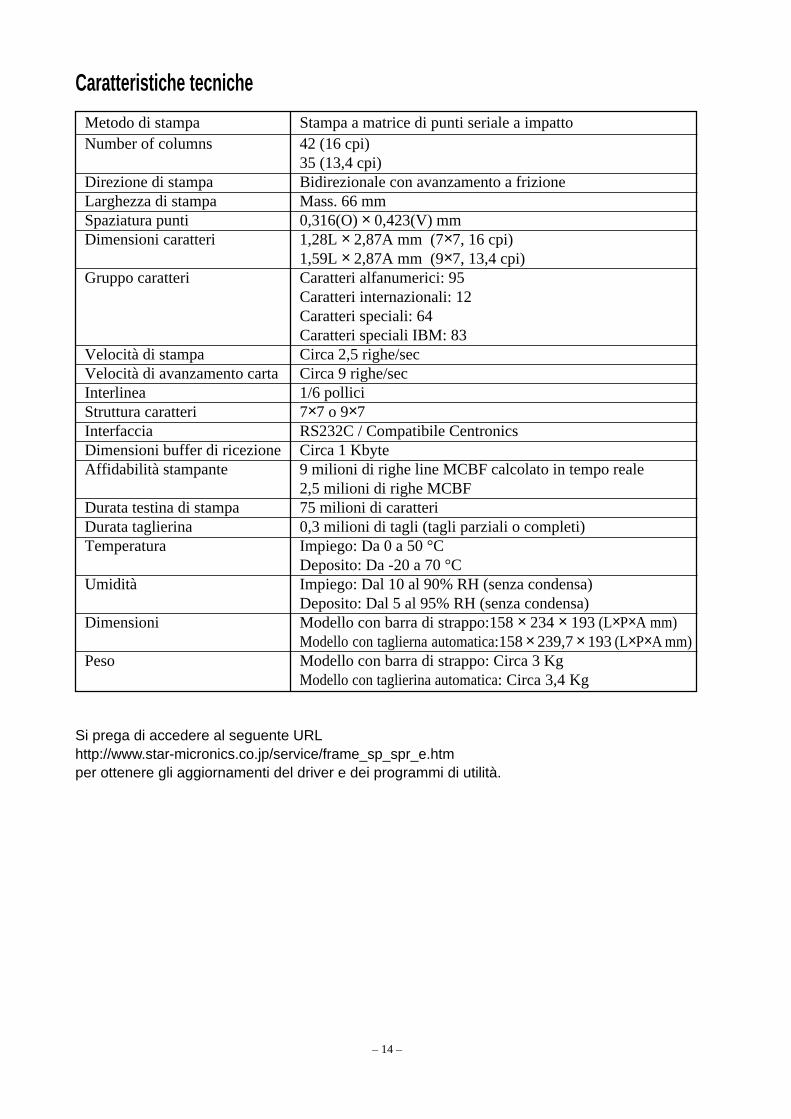
Metodo di stampa Stampa a matrice di punti seriale a impattoNumber of columns 42 (16 cpi)
35 (13,4 cpi)Direzione di stampa Bidirezionale con avanzamento a frizioneLarghezza di stampa Mass. 66 mmSpaziatura punti 0,316(O) × 0,423(V) mmDimensioni caratteri 1,28L × 2,87A mm (7×7, 16 cpi)
1,59L × 2,87A mm (9×7, 13,4 cpi)Gruppo caratteri Caratteri alfanumerici: 95
Caratteri internazionali: 12Caratteri speciali: 64Caratteri speciali IBM: 83
Velocità di stampa Circa 2,5 righe/secVelocità di avanzamento carta Circa 9 righe/secInterlinea 1/6 polliciStruttura caratteri 7×7 o 9×7Interfaccia RS232C / Compatibile CentronicsDimensioni buffer di ricezione Circa 1 KbyteAffidabilità stampante 9 milioni di righe line MCBF calcolato in tempo reale
2,5 milioni di righe MCBFDurata testina di stampa 75 milioni di caratteriDurata taglierina 0,3 milioni di tagli (tagli parziali o completi)Temperatura Impiego: Da 0 a 50 °C
Deposito: Da -20 a 70 °CUmidità Impiego: Dal 10 al 90% RH (senza condensa)
Deposito: Dal 5 al 95% RH (senza condensa)Dimensioni Modello con barra di strappo:158 × 234 × 193 (L×P×A mm)
Modello con taglierna automatica:158 × 239,7 × 193 (L×P×A mm)Peso Modello con barra di strappo: Circa 3 Kg
Modello con taglierina automatica: Circa 3,4 Kg
Caratteristiche tecniche
Si prega di accedere al seguente URLhttp://www.star-micronics.co.jp/service/frame_sp_spr_e.htmper ottenere gli aggiornamenti del driver e dei programmi di utilità.

– 1 –
IMPRESORA DE MAIMPRESORA DE MAIMPRESORA DE MAIMPRESORA DE MAIMPRESORA DE MATRIZ DETRIZ DETRIZ DETRIZ DETRIZ DEPUNTOSPUNTOSPUNTOSPUNTOSPUNTOS
SP200 SERIES
MANUAL DEL USUARIO

– 2 –
Comisión Federal de ComunicacionesDeclaración de interferencias de
radiofrecuencias
Este equipo ha sido probado y se ha determinado que cumple con las limitaciones de un dispositivo digital de Clase A, conconformidad al Apartado 15 de la normativa de FCC. Estas limitaciones están diseñadas para proporcionar una protecciónrazonable contra las interferencias perjudiciales en un entorno comercial. Este equipo genera, utiliza y puede irradiarenergía de radiofrecuencia y, si no se instala y usa de acuerdo con el manual de instrucciones, puede provocar interferenciasperjudiciales a las comunicaciones de radio. Es probable que la utilización de este equipo en una zona residencial provoqueinterferencias perjudiciales, en cuyo caso se pedirá al usuario que corrija la interferencia a su propio cargo.Para cumplir con el Estándar federal de interferencias de ruido, este equipo necesita un cable blindado.Esta declaración se aplicará sólo a las impresoras comercializadas en los Estados Unidos.
Departamento Canadiense de ComunicacionesDeclaración de interferencias
de radiofrecuencias
Este aparato digital no excede los límites de Clase A sobre emisiones de ruido desde un dispositivo digital, tal y como seestablece en las Regulaciones de Interferencias de Radio del Departamento Canadiense de Comunicaciones.Le présent appareil numérique n’émet pas de bruits radioélectriques dépassant les limites applicables aux appareils numériques de laclasse A prescrites dans le Règlement sur le brouillage radioélectrique édicté par le ministère des Communications du Canada.La declaración anterior sólo se aplica a las impresoras comercializadas en Canadá.
CEDeclaración de conformidad del fabricante
Directiva del Consejo de la CE 89/336/CEE de 3 de mayo de 1989Este producto se ha diseñado y fabricado de acuerdo con los Estándares Internacionales EN 61000-6-3/10.2001 y EN55024/09.98, según lo estipulado en la Directiva de Compatibilidad Electromagnética de la Comunidad Europea desdemayo de 1989.
Directiva del Consejo de la CE 73/23/CEE y 93/68/CEE del 22 de julio de 1993Este producto se ha diseñado y fabricado de acuerdo con los Estándares Internacionales EN 60950, según lo estipulado enla Directiva de Bajo Voltaje de la Comunidad Europea desde julio de 1993.La declaración anterior sólo se aplica a las impresoras comercializadas en la Unión Europea.
Reconocimiento de marcasSP200: Star Micronics Co., Ltd.ESC/POS: Seiko Epson Corporation
Aviso⇑ Reservados todos los derechos. Se prohíbe la reproducción total o parcial de este manual, por cualquier medio, sin el
permiso expreso de STAR.⇑ El contenido de este manual está sujeto a cambios sin previo aviso.⇑ A pesar de los esfuerzos realizados por asegurar la precisión del contenido de este manual en el momento de la
impresión, podrían detectarse errores. Si éste es el caso, STAR apreciaría enormemente le fueran comunicados.⇑ Pese a todo, STAR no se hace responsable de los errores que puedan aparecer en este manual.
© Copyright 2003 Star Micronics Co., LTD.
– 3 –
Información de seguridad
ImportanteAntes de realizar conexiones, asegúrese de que la impresora está apagada y desconectada de la tomade CA, y de que el ordenador está apagado.
ImportanteNo conecte una línea de teléfono al conector de la unidad para periféricos. Si lo hace, podría dañarla impresora.Además, por motivos de seguridad, no conecte cables al conector de la unidad externa si existe laprobabilidad de que conserve voltaje residual.
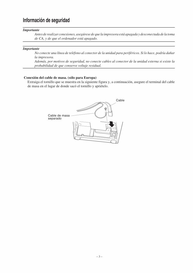
Conexión del cable de masa. (sólo para Europa)Extraiga el tornillo que se muestra en la siguiente figura y, a continuación, asegure el terminal del cablede masa en el lugar de donde sacó el tornillo y apriételo.
Cable
Cable de masaseparado

– 4 –
Desembalaje
Elección de una ubicación para la impresoraAntes de desembalar la impresora, dedique unos minutos a pensar dónde la va a utilizar.Cuando lo haga, recuerde los siguientes puntos:
� Elija una superficie plana y firme en la que la impresora no esté expuesta a vibraciones.� La toma de alimentación a la que conectará la impresora debe estar cerca y libre de
obstrucciones.� Asegúrese de que la impresora está lo bastante cerca del ordenador host para poder
conectarlos.� Asegúrese de que la impresora no queda expuesta a la luz solar directa.� Asegúrese de que la impresora está bien alejada de radiadores y otras fuentes de calor
extremo.� Asegúrese de que el área circundante está limpia, seca y sin polvo.� Asegúrese de que la impresora está conectada a una toma de alimentación que funcione.
No debe estar en el mismo circuito eléctrico que fotocopiadoras, frigoríficos y otrosaparatos que puedan provocar subidas de tensión.
� Asegúrese de que la habitación en la que va a utilizar la impresora no está demasiadohúmeda.
� Impresora� Manual del usuario� Cartucho de cinta� Núcleo de ferrita (sólo para Europa)� Pasador (sólo para Europa)
Impresora
Manual del usuario Cartucho de cinta
Núcleo de ferrita (sólopara Europa)
Pasador (sólo paraEuropa)

– 5 –
Consumibles
Cuando los consumibles se agoten, utilice los que se especifican en la siguiente tabla.
(1) Especificaciones del rollo de papelTipo de papel: Papel para copia sin carbón de gramaje normalAncho del papel: 76±0,5 mm (3,0 pulgadas)Diámetro del rollo: ø85 mm (3,35 pulgadas) máx.Diámetro interno del rollo: ø12±1 mm
Nota: No se debe pegar el papel al núcleo.Grosor: Modelo de barra de corte (una sola hoja) 70 µm a 100 µm
(copias) Original + 2 copias (Máx. 200 µm) Modelo de cortadora automática(una sola hoja) 70 µm a 100 µm
(copias) Original +1 copias (Máx. 100 µm)Nota: La cortadora automática incluida en este modelo
se ha diseñado para un grosor máximo de papel de100 µm. Este grosor se ha calculado según unacapacidad máxima de papel de 2 capas, donde cadahoja se establece en 50 µm . Si excede los 100 µm,la especificación de la cortadora automática delgrosor del papel no proporcionará un corteadecuado.
(2) Especificaciones de cinta de tintaTipo de cinta: Cassette de cartuchoColor: Tipo SP212/242: Monocolor (negro o púrpura)
Tipo SP216/246: Bicolor (blanco y rojo)Material de la cinta: Nailon 66 (#40 denier)Duración de la cinta: Monocolor:
3.000.000 caracteres en color púrpura1.200.000 caracteres en color negroBicolor:600.000 caracteres en color negro300.000 caracteres en color rojo

– 6 –
Panel de control
1 Interruptor en línea (ON LINE)Alterna entre el estado en línea (ON LINE) y sin línea(OFF LINE) de la impresora. Esta alternancia entreestados sólo es posible una vez cargado el papel en laimpresora.
2 Interruptor de alimentación (FEED)• Si se pulsa este interruptor y, a continuación, se suelta
en 0,5 segundos, se carga el papel línea a línea.• Si se mantiene pulsado este interruptor durante más de
0,5 segundos, se carga el papel de forma continua.(Esta función de alimentación del papel es posible tantoen los modos ON LINE como OFF LINE.)
3 Luz de encendido (POWER) (LED verde)• Se enciende cuando la impresora está activada.• Parpadea cuando no hay papel, se produce un error mecánico, si hay una alarma por la detección
de una temperatura excesiva en el cabezal o cuando se ha producido un error en la CPU.• Si se ha agotado el papel, cargue papel nuevo y pulse el interruptor ON LINE.• Si parpadea la luz de encendido por haberse producido un error mecánico, desconecte la
alimentación y solucione la causa del error; a continuación, vuelva a conectar la alimentación pararestablecer la impresora.
• Si parpadea la luz de encendido por la detección de una temperatura excesiva en el cabezal, laimpresora se establecerá automáticamente cuando disminuya la temperatura.
4 Luz en línea (ON LINE) (LED verde)LED encendido: La impresora está ON LINELED apagado: La impresora está OFF LINELED parpadeando: Error en la CPU
Si las luces POWER y ON LINE se encienden simultáneamente, se ha producido un error en laCPU.
Carga del cartucho de cinta (Modelo de barra de corte)
1 Desconecte la impresora.
2 Levante la cubierta aproximadamente 3 cm.Mantenga la cubierta inclinada en este ángulo y,a continuación, tire de ella hacia usted paraquitarla.
Cubierta
Apagado
ON LINEPOWER FEED
3 POWER lamp (Green LED)
4 ON LINE lamp (Green LED)
1 ON LINE switch
2 FEED switch
– 7 –
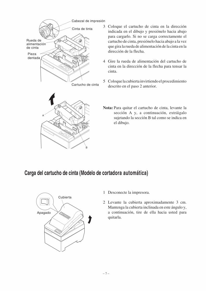
3 Coloque el cartucho de cinta en la direcciónindicada en el dibujo y presiónelo hacia abajopara cargarlo. Si no se carga correctamente elcartucho de cinta, presiónelo hacia abajo a la vezque gira la rueda de alimentación de la cinta en ladirección de la flecha.
4 Gire la rueda de alimentación del cartucho decinta en la dirección de la flecha para tensar lacinta.
5 Coloque la cubierta invirtiendo el procedimientodescrito en el paso 2 anterior.
Nota: Para quitar el cartucho de cinta, levante lasección A y, a continuación, extráigalosujetando la sección B tal como se indica enel dibujo.
Carga del cartucho de cinta (Modelo de cortadora automática)
1 Desconecte la impresora.
2 Levante la cubierta aproximadamente 3 cm.Mantenga la cubierta inclinada en este ángulo y,a continuación, tire de ella hacia usted paraquitarla.
Cabezal de impresión
Cinta de tinta
Rueda dealimentaciónde cinta
Piezadentada
Cartucho de cinta
A
B
Cubierta
Apagado

– 8 –
4 Coloque el cartucho de cinta en la direcciónindicada en el dibujo y presiónelo hacia abajopara cargarlo. Si no se carga correctamente elcartucho de cinta, presiónelo hacia abajo a la vezque gira la rueda de alimentación de la cinta en ladirección de la flecha.
5 Gire la rueda de alimentación del cartucho decinta en la dirección de la flecha para tensar lacinta.
6 Cierre la cortadora automática.
7 Coloque la cubierta invirtiendo el procedimientodescrito en el paso 2 anterior.
Nota: Para quitar el cartucho de cinta, levante lasección A y, a continuación, extráigalosujetando la sección B tal como se indicaen el dibujo.
A
B
3 Levante la cortadora automática y colóquela enposición vertical tal y como se indica en eldibujo.
Cortadoraautomática
Cabezal de impresiónCinta de tinta
Cortadoraautomática
Rueda dealimentaciónde cinta
Pieza dentada
Cartucho decinta

– 9 –
Carga del papel (Modelo de barra de corte)
1 Levante la cubierta aproximadamente 3 cm.Mantenga la cubierta inclinada en este ángulo y,a continuación, tire de ella hacia usted paraquitarla.
2 Corte el extremo del rollo de papelperpendicularmente.
3 Asegúrese de que la impresora está encendida.
4 Siguiendo la dirección del rollo de papel, inserte elextremo superior del papel por debajo de la guía delpapel hasta que haga tope. Si está instalado el rollode papel, el extremo superior del papel saleautomáticamente por la salida de papel.
5 Mueva el portarrollos en la dirección de la flechae inserte el rollo de forma que los orificios delnúcleo se alineen con los ejes del portarrollos.Suelte el portarrollos para fijar el papel.
6 Si el núcleo del rollo de papel no se ha alineadocorrectamente con el portarrollos, no se podráajustar correctamente la cubierta hasta que sehaya corregido la posición del papel.
7 Pulse el interruptor de alimentación (FEED) paracargar aproximadamente 10 cm de papel.
8 Inserte el extremo superior del papel en la ranurade la barra de corte y, a continuación, coloque lacubierta invirtiendo el procedimiento realizadopara quitarla en el paso 1 anterior.
Nota: Si aparece la marca de fin de papel, sustituyael rollo antes de que se agote.
Cubierta
Interruptor dealimentación(FEED)
Rollo depapel Núcleo
Eje
Portarrollos
Rollo depapel
CubiertaVarilla deposición
Portarrollos
Barra decorte
Interruptor dealimentación(FEED)

– 10 –
2 Corte el extremo del rollo de papel perpen-dicularmente.
3 Asegúrese de que la impresora está encendida.4 Siguiendo la dirección del rollo de papel, inserte el
extremo superior del papel por debajo de la guía delpapel hasta que haga tope. Si está instalado el rollode papel, el extremo superior del papel saleautomáticamente por la salida de papel. Despuésde cargar 2 cm de papel, éste se cortaautomáticamente.
5 Mueva el portarrollos en la dirección de la flechae inserte el rollo de forma que los orificios delnúcleo se alineen con los ejes del portarrollos.Suelte el portarrollos para fijar el papel.
6 Si el núcleo del rollo de papel no se ha alineadocorrectamente con el portarrollos, no se podráajustar correctamente la cubierta hasta que sehaya corregido la posición del papel.
7 Pulse el interruptor de alimentación (FEED) paracargar aproximadamente 10 cm de papel.
Carga del papel (Modelo de cortadora automática)
1 Levante la cubierta aproximadamente 3 cm.Mantenga la cubierta inclinada en este ángulo y,a continuación, tire de ella hacia usted paraquitarla.
Cubierta
Interruptor dealimentación(FEED)
Rollo depapel Núcleo
Eje
Portarrollos
Rollo depapel
CubiertaVarilla deposición
Portarrollos

– 11 –
9 Tire del borde del papel para tensarlo y, acontinuación, baje la cortadora automática.
10 Inserte el papel en la salida de papel y, acontinuación, coloque nuevamente la cubiertainvirtiendo los pasos realizados para quitarla.
Nota: Si aparece la marca de fin de papel, sustituyael rollo antes de que se agote.
8 Inserte el extremo del rollo de papel en la ranurade inserción de papel de la cortadora automática.
• Si se utiliza papel copia, inserte sólo el original(el papel superior) en la ranura de la cortadoraautomática. Inserte el papel que desea copiar (elpapel inferior) entre el rodillo y la cortadoraautomática.
CortadoraautomáticaRanura
de inserciónde papel
Papel superior
Interruptor dealimentación(FEED)
Cabezal deimpresión
Ranura deinserción depapel
Rodillo
Papel inferior Cabezal deimpresión
Rodillo
Papel inferior
Papel superior
Cortadoraautomática
Salida depapel
Cortadoraautomática
Ranura deinserción depapel

– 12 –
Configuración de los interruptores DIP: Tipo de interfaz paralela
INT-DIPInt. Función ON OFF
1 Detección de falta de papel Válido No válido
2 Código de control CR No válido Válido
3
4 Juego de caracteres internacional Véase a continuación
5
6 Búfer de datos Disponible No disponible
(approx. 1 Kb) (1 línea)
7Configuración de generación de caracteres Véase a continuación
8
La configuración de fábrica de los interruptores DIP es todos activados (ON).
Juego de caracteres internacionalInt. EE.UU. Francia Alemania Inglaterra Dinamarca Suecia Italia España
3 ON OFF ON OFF ON OFF ON OFF
4 ON ON OFF OFF ON ON OFF OFF
5 ON ON ON ON OFF OFF OFF OFF
Generación de caracteresInt. US EC JP JP
7 ON ON OFF OFF
8 ON OFF ON OFF
81ON
OFF

– 13 –
Configuración de los interruptores DIP: Tipo de interfaz serie
INT-DIPInt. Función ON OFF
1 Modo de comando Modo STAR Modo VeriFone
2 Código de control CR No válido Válido
3
4 Juego de caracteres internacional Véase a continuación
5
6Velocidad de transmision de datos Véase a continuación
7
8 Bit de datos 8 bits de datos 7 bits de datos
9 Comprobación de paridad No Sí
10 Paridad Impar Par
La configuración de fábrica de los interruptores DIP es todos activados (ON).
Juego de caracteres internacionalInt. EE.UU. Francia Alemania Inglaterra Dinamarca Suecia Italia España
3 ON OFF ON OFF ON OFF ON OFF
4 ON ON OFF OFF ON ON OFF OFF
5 ON ON ON ON OFF OFF OFF OFF
101ON
OFF
Velocidad de transmisión de datos (velocidad en baudios)Velocidad en baudios Interruptor 6 Interruptor 7
1200 OFF OFF
2400 OFF ON
4800 ON OFF
9600 ON ON
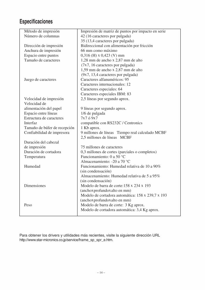
– 14 –
Método de impresión Impresión de matriz de puntos por impacto en serieNúmero de columnas 42 (16 caracteres por pulgada)
35 (13,4 caracteres por pulgada)Dirección de impresión Bidireccional con alimentación por fricciónAnchura de impresión 66 mm como máximoEspacio entre puntos 0,316 (H) x 0,423 (V) mmTamaño de caracteres 1,28 mm de ancho x 2,87 mm de alto
(7x7, 16 caracteres por pulgada)1,59 mm de ancho x 2,87 mm de alto
(9x7, 13,4 caracteres por pulgada)Juego de caracteres Caracteres alfanuméricos: 95
Caracteres internacionales: 12Caracteres especiales: 64Caracteres especiales IBM: 83
Velocidad de impresión 2,5 líneas por segundo aprox.Velocidad dealimentación del papel 9 líneas por segundo aprox.Espacio entre líneas 1/6 de pulgadaEstructura de caracteres 7x7 ó 9x7Interfaz compatible con RS232C / CentronicsTamaño de búfer de recepción 1 Kb aprox.Confiabilidad de impresora 9 millones de líneas Tiempo real calculado MCBF
2,5 millones de líneas MCBFDuración del cabezalde impresión 75 millones de caracteresDuración de cortadora 0,3 millones de cortes (parciales o completos)Temperatura Funcionamiento: 0 a 50 °C
Almacenamiento: -20 a 70 °CHumedad Funcionamiento: Humedad relativa de 10 a 90%
(sin condensación)Almacenamiento: Humedad relativa de 5 a 95%
(sin condensación)Dimensiones Modelo de barra de corte:158 x 234 x 193
(anchoxprofundoxalto en mm)Modelo de cortadora automática: 158 x 239,7 x 193
(anchoxprofundoxalto en mm)Peso Modelo de barra de corte: 3 Kg aprox.
Modelo de cortadora automática: 3,4 Kg aprox.
Especificaciones
Para obtener los drivers y utilidades más recientes, visite la siguiente dirección URLhttp://www.star-micronics.co.jp/service/frame_sp_spr_e.htm.

– 1 –
IMPRESSORA DE MAIMPRESSORA DE MAIMPRESSORA DE MAIMPRESSORA DE MAIMPRESSORA DE MATRIZTRIZTRIZTRIZTRIZDE PONTOSDE PONTOSDE PONTOSDE PONTOSDE PONTOS
SÉRIE SP200
MANUAL DO UTILIZADOR

– 2 –
FCC (“Federal Communications Commission”)Interferência na frequência de rádio
Declaração
Este equipamento foi testado e concluiu-se que está em conformidade com os limites para um dispositivo digital de classeA, de acordo com a secção 15 das normas da FCC. Estes limites foram concebidos para disponibilizar uma protecçãorazoável contra as interferências perigosas quando o equipamento é utilizado num ambiente comercial. Este equipamentogera, utiliza e pode irradiar energia de frequência rádio e se não for instalado e utilizado de acordo com o manual deinstruções pode provocar interferências perigosas nas comunicações via rádio. A utilização deste equipamento numa árearesidencial poderá provocar interferências perigosas. Se tal for o caso, o utilizador terá de custear a correcção dasinterferências.Para estar em conformidade com a norma “Federal Noise Interference”, este equipamento necessita de utilizar um caboblindado.Esta declaração só se aplica às impressoras comercializadas nos E.U.A..
Declaração doDepartamento Canadiano de ComunicaçõesNormas relativas às interferências via rádio
Este aparelho digital não excede os limites da classe A para as emissões de ruído do rádio provenientes de aparelhos digitaisdefinidos nas normas relativas a interferências provenientes do rádio emitidas pelo Departamento Canadiano de Comunicações.Le présent appareil numérique n’émet pas de bruits radioélectriques dépassant les limites applicables aux appareils numériques de laclasse A prescrites dans le Règlement sur le brouillage radioélectrique édicté par le ministère des Communications du Canada.A declaração acima aplica-se apenas a impressoras comercializadas no Canadá.
CEDeclaração de conformidade do fabricante
Directiva do Conselho da CE 89/336/EEC, de 3 de Maio de 1989Este produto foi concebido e fabricado de acordo com as normas internacionais EN 61000-6-3/10.2001 e EN 55024/09.98,no seguimento das provisões da directiva relativa à compatibilidade electromagnética da Comunidade Europeia, emitida emMaio de 1989.
Directiva do Conselho da UE 73/23/EEC e 93/68/EEC, emitida no dia 22 de Julho de 1993Este produto foi concebido e fabricado de acordo com as normas internacionais EN 60950, no seguimento das provisões dadirectiva relativa a baixas tensões da Comunidade Europeia, emitida em Julho de 1993.A declaração acima aplica-se apenas a impressoras comercializadas nos E.U.A..
Reconhecimentos das marcas comerciaisSP200: Star Micronics Co., Ltd.ESC/POS: Seiko Epson Corporation
Aviso• Todos os direitos reservados. Não é permitida a reprodução de qualquer parte deste manual sob qualquer forma, sem a permissão
expressa da STAR.• O conteúdo deste manual está sujeito a alterações sem aviso prévio.• Foram realizados todos os esforços para assegurar a exactidão do conteúdo deste manual quando foi impresso. Contudo,
se forem detectados alguns erros, a STAR agradecia imenso que fosse informada desses erros.• Desta forma, a STAR não assume qualquer tipo de responsabilidade pelos erros existentes neste manual.
© Copyright 2003 Star Micronics Co., LTD.

– 3 –
Informações relativas à segurança
Importante!Certifique-se de que a impressora está desactivada e desligada da tomada AC e de que o computadorestá desligado antes de realizar as ligações.
Importante!Não ligue uma linha telefónica ao conector da unidade periférica. Se o fizer, pode danificar aimpressora.Além disso, por questões de segurança, não ligue nenhum fio ao conector da unidade externa, sehouver a hipótese de transportar tensão periférica.
Ligação do fio terra. (Apenas na Europa.)Retire o parafuso mostrado na figura abaixo e, de seguida, aperte o terminal do fio terra ao local onde oparafuso foi removido e aperte o parafuso.
Fio terraindependente
Cabo

– 4 –
Desempacotamento
Escolha um local para colocar a impressoraAntes de desempacotar a impressora, demore alguns minutos a pensar onde planeia utilizá-la. Lembre-se dos seguintes pontos quando pensar nisso:
✓ Escolha uma superfície firme e plana onde a impressora não seja exposta a vibrações.✓ A tomada que planeia ligar à corrente deverá estar perto e desobstruída.✓ Certifique-se de que a impressora está suficientemente perto do computador anfitrião
para ligar os dois dispositivos.✓ Certifique-se de que a impressora não está exposta à luz solar directa.✓ Certifique-se de que a impressora está suficientemente afastada de aquecedores e de
outras fontes de calor extremo.✓ Certifique-se de que a área circundante está limpa, seca e sem pó.✓ Certifique-se de que a impressora está ligada a uma tomada fidedigna. A tomada não
pode estar instalada no mesmo circuito eléctrico do que as fotocopiadoras, refrigeradoresou outras aplicações que provoquem picos de corrente.
✓ Certifique-se de que a sala onde está a utilizar a impressora não é demasiado húmida.
✓ Impressora✓ Manual do utilizador✓ Cartucho da fita✓ Núcleo de ferrite (apenas nos E.U.A.)✓ Fixador (apenas nos E.U.A.)
Impressora
Manual doutilizador Cartucho da fita
Fixador (apenasnos E.U.A.)
Núcleo de ferrite (apenasnos E.U.A.)

– 5 –
Itens consumíveis
Quando os itens consumíveis acabarem, utilize os itens especificados na tabela abaixo.
(1) Especificações do rolo de papelTipo de papel: Papel de cópia sem carbono e com uma ligação normalLargura do papel: 76±0,5 mm (3,0 polegadas)Diâmetro do rolo: ø85 mm (3,35 polegadas) no máximo.Diâmetro interno do rolo: ø12±1 mm
Nota: o papel tem de estar colado ao núcleo.Espessura: Modelo da barra de resistência (única) entre 70 µm e 100 µm
(cópias) Original + 2 cópias (Máximo de 200 µm) Modelo do cortador automático (única) entre 70 µm e 100 µm
(cópias) Original + 1 cópias (Máximo de 100 µm)Nota: o cortador automático incorporado neste modelo
de cortador automático, foi concebido para umaespessura de papel máxima de 100 µm. Estaespessura está definida para uma capacidademáxima do papel de 2 camadas, onde cada folhaestá definida para 50 µm . Se exceder aespecificação do cortador automático da espessurado papel de 100, µm não assegura o corte correcto.
(2) Especificações da tinta da fitaTipo de fita: CartuchoCor: Tipo SP212/242: Cor única (púrpura ou preto)
Tipo SP216/246: Duas cores (preto e vermelho)Material da fita: Nylon 66 (#40 denier)Duração da fita: Uma única cor:
Púrpura 3000000 caracteresPreto 1200000 caracteresDuas cores:Preto em 600000 caracteres de duas coresVermelho em 300000 caracteres de duas cores

– 6 –
Painel de controlo
➀ Botão ON LINEAlterna a impressora entre ON LINE e OFF LINE. Aalternância da impressora entre ON LINE e OFF LINE,só é possível quando o papel está introduzido naimpressora.
➁ Botão FEED• Quando este botão é premido e, de seguida, libertado no
espaço de 0,5 segundos, o papel é introduzido linha alinha.
• Quando este botão não é premido durante mais do que0,5 segundos, o papel é alimentado continuamente.(A operação de alimentação do papel acima referida, épossível de realizar nos modos ON LINE e OFF LINE.)➂ Botão POWER (LED verde)
• Acende quando a impressora está ligada.• Pisca quando o papel está fora, quando ocorrem erros mecânicos, quando há um alarme devido
à detecção de temperatura na cabeça ou quando ocorre um erro na CPU.• Se o papel estiver fora, introduza papel novo e prima o botão ON LINE.• Quando a lâmpada POWER pisca por causa da ocorrência de um erro mecânico, desligue a
impressora e corrija o motivo do erro mecânico e, de seguida, volte a ligar a impressora parareiniciar o dispositivo.
• Se a lâmpada POWER piscar por causa do disparo do alarme de detecção da temperatura dacabeça, a impressora é definida automaticamente quando a temperatura da cabeça baixa.
➃ Lâmpada ON LINE (LED verde)LED acesso: a impressora está ON LINELED apagado: a impressora está OFF LINELED a piscar: erro na CPU
Quando as lâmpadas POWER e ON LINE acedem simultaneamente, é porque ocorreu um errona CPU.
Colocação do cartucho da fita (modelo da barra de resistência)
➀ Desligue a impressora.
➁ Levante a tampa aproximadamente 3 cm. Segurena tampa inclinada com este ângulo e, de seguida,desloque-a na sua direcção para a retirar.
Tampa
Desligar
ON LINEPOWER FEED
3 POWER lamp (Green LED)
4 ON LINE lamp (Green LED)
1 ON LINE switch
2 FEED switch

– 7 –
➂ Coloque o cartucho da fita na direcção mostradana figura e, de seguida, prima-a para o introduzir.Se a colocação do cartucho da fita não estivercorrecta, prima o cartucho, enquanto roda obotão de alimentação da fita na direcção da seta.
➃ Rode o botão de alimentação da fita do cartuchoda fita na direcção da seta para esticar a fita.
➄ Para voltar a colocar a tampa realize oprocedimento referido no passo ➁ acima.
Nota: quando remover o cartucho da fita, levante asecção A e, de seguida, retire-a segurando nasecção B como é apresentado na figura.
Colocação do cartucho da fita (modelo do cortador automático)
➀ Desligue a impressora.
➁ Levante a tampa aproximadamente 3 cm. Segurena tampa inclinada com este ângulo e, de seguida,desloque-a na sua direcção para a retirar.
Cabeça de impressão
Fita da tinta
Botão dealimentaçãoda fita
Parteranhurada
Cartucho da fita
A
B
Tampa
Desligar

– 8 –
➃ Coloque o cartucho da fita na direcção mostradana figura e, de seguida, prima-a para o introduzir.Se a colocação do cartucho da fita não estivercorrecta, prima o cartucho, enquanto roda obotão de alimentação da fita na direcção da seta.
➄ Rode o botão de alimentação da fita do cartuchoda fita na direcção da seta para esticar a fita.
➅ Feche o cortador automático.
➆ Para voltar a colocar a tampa realize oprocedimento referido no passo ➁ acima.
Nota: quando remover o cartucho da fita, levantea secção A e, de seguida, retire-a segurandona secção B como é apresentado na figura.
A
B
➂ Levante o cortador automático e coloque-o numaposição vertical, como mostra a figura.
Cortadorautomático
Cabeça deimpressão
Fita datinta
Cortadorautomático
Botão dealimentaçãoda fita
Parteranhurada
Cartucho da fita

– 9 –
Colocação do papel (modelo da barra de resistência)
➀ Levante a tampa aproximadamente 3 cm.Mantenha a tampa inclinada para este ângulo e,de seguida, desloque-a na sua direcção para aretirar.
➁ Corte a extremidade frontal do papel do rolo naperpendicular.
➂ Confirme se a impressora está ligada.
➃ Enquanto observa a direcção do papel do rolo,introduza a extremidade superior do papel porbaixo do guia do papel. Se o papel do rolo estivercolocado, a extremidade do topo do papel saiautomaticamente da saída do papel.
➄ Desloque o fixador do rolo de papel na direcçãoda seta e introduza o rolo de forma que osorifícios localizados no núcleo fiquem alinhadoscom os eixos do fixador do rolo de papel. Liberteo fixador do rolo de papel para fixar o papel.
➅ Se o núcleo do rolo de papel não estivercorrectamente alinhado com o fixador do rolo depapel, não é possível colocar a tampa até aposição do papel estar corrigida.
➆ Prima o botão FEED (alimentação do papel) paraalimentar o papel aproximadamente 10 cm.
➇ Introduza a extremidade superior do papel naranhura da barra de resistência e, de seguida,coloque a tampa através da realização do processoinverso descrito no passo ➀ acima.
Nota: quando a marca da extremidade do papelaparecer na folha, substitua o papel do roloantes que este acabe.
Tampa
BotãoFEED
Papel do rolo
Núcleo
Eixo
Fixador do rolode papel
Papel dorolo
TampaSuporte deposicionamento
Fixador do rolo depapel
Barra deresistência
Botão FEED

– 10 –
➁ Corte a extremidade frontal do papel do rolo naperpendicular.
➂ Confirme se a impressora está ligada.➃ Enquanto observa a direcção do papel do rolo,
introduza a extremidade superior do papel porbaixo do guia do papel. Se o papel do rolo estivercolocado, a extremidade do topo do papel saiautomaticamente da saída do papel. Depois de 2cm do papel terem sido extraídos, o papel écortado automaticamente.
➄ Desloque o fixador do rolo de papel na direcçãoda seta e introduza o rolo de forma que osorifícios localizados no núcleo fiquem alinhadoscom os eixos do fixador do rolo de papel. Liberteo fixador do rolo de papel para fixar o papel.
➅ Se o núcleo do rolo de papel não estivercorrectamente alinhado com o fixador do rolo depapel, não é possível colocar a tampa até aposição do papel estar corrigida.
➆ Prima o botão FEED (alimentação do papel) paraalimentar o papel aproximadamente 10 cm.
Colocação do papel (modelo do cortador automático)
➀ Levante a tampa aproximadamente 3 cm.Mantenha a tampa inclinada para este ângulo e,de seguida, desloque-a na sua direcção para aretirar.
Tampa
BotãoFEED
Papel dorolo Núcleo
Eixo
Fixador do rolode papel
Papel dorolo
TampaSuporte deposicionamento
Fixador do rolo depapel

– 11 –
➈ Puxe a extremidade do papel para o esticar e, deseguida, baixe o cortador automático.
➉ Introduza o papel através da saída do papel e, deseguida, volte a colocar a tampa através darealização dos passos no sentido inverso.
Nota: quando a marca da extremidade do papelaparecer na folha, substitua o papel do roloantes que este acabe.
➇ Introduza a ponta do papel do rolo na ranhura docortador automático de papel.
• Quando utilizar papel de cópia, introduza apenaso original (o papel de cima) na ranhura do cortadorautomático. Introduza o papel a ser copiado (opapel inferior) entre o rolo e o cortador automático.
Cortadorautomático
Papelintroduçãoranhura
Papel superior
Botão FEED
Cabeça deimpressão
Ranhura paraintrodução dopapel
Rolo
Papel inferior Cabeça deimpressão
Rolo
Papel inferior
Papel superior
Cortadorautomático
Saída dopapel
Cortadorautomático
Ranhura paraintrodução dopapel
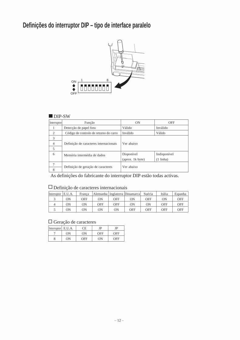
– 12 –
Definições do interruptor DIP – tipo de interface paralelo
DIP-SWInterruptor Função ON OFF
1 Detecção de papel fora Válido Inválido
2 Código de controlo de retorno do carro Inválido Válido
3
4 Definição de caracteres internacionais Ver abaixo
5
6 Memória intermédia de dados Disponível Indisponível
(aprox. 1k byte) (1 linha)
7 Definição de geração de caracteres Ver abaixo
8
As definições do fabricante do interruptor DIP estão todas activas.
Definição de caracteres internacionaisInterruptor E.U.A. França Alemanha Inglaterra Dinamarca Suécia Itália Espanha
3 ON OFF ON OFF ON OFF ON OFF
4 ON ON OFF OFF ON ON OFF OFF
5 ON ON ON ON OFF OFF OFF OFF
Geração de caracteresInterruptor E.U.A. CE JP JP
7 ON ON OFF OFF
8 ON OFF ON OFF
81ON
OFF

– 13 –
Definições do interruptor DIP – tipo de interface série
DIP-SWInterruptor Função ON OFF
1 Modo de comando Modo STAR Modo VeriFone
2 Código de controlo de retorno do carro Inválido Válido
3
4 Definição de caracteres internacionais Ver abaixo
5
6 Velocidade de transmissão de dados Ver abaixo
7
8 Bit de dados Bit de dados 8 Bit de dados 7
9 Verificação da paridade Não Sim
10 Paridade Ímpar Par
As definições do fabricante do interruptor DIP estão todas activas.
Definição de caracteres internacionaisInterruptor E.U.A. França Alemanha Inglaterra Dinamarca Suécia Itália Espanha
3 ON OFF ON OFF ON OFF ON OFF
4 ON ON OFF OFF ON ON OFF OFF
5 ON ON ON ON OFF OFF OFF OFF
101ON
OFF
Velocidade de transmissão de dadosVelocidade de transmissão Interruptor 6 Interruptor 7
1200 OFF OFF
2400 OFF ON
4800 ON OFF
9600 ON ON

– 14 –
Método de impressão Impressão matriz de pontos por impacto sérieNúmero de colunas 42 (16 cpi)
35 (13,4 cpi)Direcção da impressão Bidireccional com alimentação por fricçãoLargura de impressão Máximo de 66 mmEspaço entre os pontos 0,316 (H) x 0,423 (V) mmTamanho dos caracteres 1,28 L x 2,87 H mm (7x7, 16 cpi)
1,59 L x 2,87 H mm (9x7, 13,4 cpi)Conjunto dos caracteres Caracteres alfanuméricos: 95
Caracteres internacionais: 12Caracteres especiais: 64Caracteres especiais da IBM: 83
Velocidade de impressão Aproximadamente 2,5 linhas/seg.Velocidade de alimentaçãodo papel Aproximadamente 9 linhas/seg.Espaçamento entre linhas 1/6 polegadasEstrutura dos caracteres 7x7 ou 9x7Interface RS232C/compatível com o CentronicsTamanho damemória intermédia recebida Aproximadamente 1K byteFiabilidade da impressora 9 milhões de linhas Tempo real calculado MCBF
2,5 milhões de linhas MCBFDuração da cabeçade impressão 75 milhões de caracteresDuração do cortador 0,3 milhões de cortes (corte total ou parcial)Temperatura Funcionamento: entre 0 e 50 °C
Armazenamento: entre -20 e 70 °CHumidade Funcionamento: entre 10 e 90% RH (sem condensação)
Armazenamento: entre 5 e 95% RH (sem condensação)Dimensões Modelo da barra de resistência:158 x 234 x 193 (LxPxA mm)
Modelo do cortador automático:158 x 239,7 x 193 (LxPxA mm)Peso Modelo da barra de resistência:Aproximadamente 3 kg
Modelo do cortador automático:Aproximadamente 3,4 kg
Especificações
Aceda ao seguinte URL:http://www.star-micronics.co.jp/service/frame_sp_spr_e.htmpara obter os mais recentes controladores e utilitários da impressora.

– 1 –
DOT MADOT MADOT MADOT MADOT MATRIX PRINTERTRIX PRINTERTRIX PRINTERTRIX PRINTERTRIX PRINTER
SP200-SERIE
GEBRUIKERSHANDLEIDING

– 2 –
Federal Communications CommissionStoring van radiofrequenties
Verklaring
Deze apparatuur blijkt volgens tests te voldoen aan de criteria voor computerapparatuur van klasse A, overeenkomstig deel15 van het FCC-reglement. Deze regels beogen een redelijke bescherming te bieden tegen storingen wanneer de apparatuurin een zakelijke omgeving wordt gebruikt. In deze apparatuur wordt elektrische energie op radiofrequenties opgewekt, diestoring kan veroorzaken in radio- en TV-ontvangst als hij niet volgens de in deze handleiding gegeven voorschriften wordtaangesloten of gebruikt. Gebruik ervan in een woonomgeving kan storing veroorzaken; in dat geval is de gebruiker verplichtom de storing op zijn kosten te verhelpen.Ingevolge de Federal Noise Interference Standard is voor deze apparatuur een afgeschermde kabel vereist.Deze verklaring is alleen van toepassing op printers die in de Verenigde Staten op de markt worden gebracht.
Verklaring van hetCanadese Ministerie van Communicatie
Voorschriften inzake Radiostoring
Deze digitale apparatuur blijft binnen de grenzen van klasse A voor radiostoringen die door digitale apparatuur wordenveroorzaakt, zoals uiteengezet in de Voorschriften inzake Radiostoring van het Canadese Ministerie van Communicatie.Le présent appareil numérique n’émet pas de bruits radioélectriques dépassant les limites applicables aux appareils numériques de laclasse A prescrites dans le Règlement sur le brouillage radioélectrique édicté par le ministère des Communications du Canada.Bovenstaande verklaring is alleen van toepassing op printers die in Canada op de markt worden gebracht.
CEConformiteitsverklaring van fabrikant
Europese richtlijn 89/336/EEC van 3 mei 1989Dit product is ontwikkeld en gefabriceerd volgens de internationale normen EN 61000-6-3/10.2001 en EN 55024/09.98zoals bepaald in de richtlijn voor elektromagnetische compatibiliteit van de Europese Gemeenschap van mei 1989.
Europese richtlijnen 73/23/EEC en 93/68/EEC van 22 juli 1993Dit product is ontwikkeld en gefabriceerd volgens de internationale normen EN 60950 zoals bepaald in delaagspanningsrichtlijn van de Europese Gemeenschap van juli 1993.Bovenstaande bepaling is alleen van toepassing op printers die in de Europese Unie op de markt worden gebracht.
Verklaring over handelsmerkenSP200: Star Micronics Co., Ltd.ESC/POS: Seiko Epson Corporation
Opmerking⇑ Alle rechten voorbehouden. Niets uit deze handleiding mag in welke vorm dan ook worden verveelvoudigd zonder
voorafgaande uitdrukkelijke toestemming van STAR.⇑ De inhoud van deze handleiding kan zonder voorafgaande kennisgeving worden gewijzigd.⇑ Tot het ter perse gaan van deze handleiding is al het mogelijke gedaan om de juistheid van de inhoud hiervan te
waarborgen. Mochten er desondanks fouten in voorkomen, zal STAR het op prijs stellen hierover te wordengeïnformeerd.
⇑ STAR aanvaardt evenwel geen aansprakelijkheid voor eventuele fouten in deze handleiding.
© Copyright 2003 Star Micronics Co., LTD.

– 3 –
Veiligheidsrichtlijnen
Belangrijk!Zorg dat de printer is uitgeschakeld, dat de voedingskabel is losgemaakt en dat de computer isuitgeschakeld als u de apparatuur gaat aansluiten.
Belangrijk!Sluit geen telefoonkabel aan op de connector voor randapparatuur. Anders kan de printer defectraken.In verband met de veiligheid mag bedrading waar mogelijk spanning op staat niet op de connectorworden aangesloten.
Aarddraad aansluiten. (Alleen EU)Draai de in onderstaande afbeelding getoonde schroef los, sluit de aarddraad hierop aan en draai de schroefweer vast.
Kabel
Afzonderlijkeaarddraad

– 4 –
Uitpakken
Kies een geschikte plaats voor de printerDenk, voordat u met uitpakken begint, even rustig na over de plaats waar de printer gebruiktzal worden. Houd daarbij rekening met de volgende punten.
� Kies een stevig en effen oppervlak waar de printer niet blootstaat aan trillingen.� Het stopcontact dat u wilt gebruiken moet zich dicht bij de printer bevinden en gemakkelijk
bereikbaar zijn.� Zorg met het oog op de aansluiting dat de printer niet te ver uit de buurt van de
hostcomputer staat.� Stel de printer niet bloot aan direct zonlicht.� Zorg voor voldoende afstand tussen de printer en verwarmingstoestellen of andere
warmtebronnen.� Houd de omgeving van de printer schoon, droog en stofvrij.� Sluit de printer aan op een betrouwbaar stopcontact. Kies geen groep waarop ook
kopieermachines, koelkasten of andere apparaten zijn aangesloten die spanningspiekenkunnen veroorzaken.
� Gebruik de printer niet in een ruimte die erg vochtig kan worden.
� Printer� Gebruikershandleiding� Lintcassette� Ferrietkern (alleen EU)� Borgstrip (alleen EU)
Printer
Lintcassette
Ferrietkern (alleen EU)
Borgstrip (alleenEU)
Gebruikershandleiding
– 5 –
Verbruiksartikelen
Zie onderstaande tabel voor aanvulling van verbruiksartikelen.
(1) Specificaties papierrolPapiertype: Gewoon bankpost- en zelfkopiërend papierPapierbreedte: 76±0,5 mmRoldiameter: max. ø85 mmBinnendiameter rol: ø12±1 mm
Opmerking: Het papier mag niet aan de kern gelijmd zijn.Dikte: Model met scheurrand (1 pagina) 70 µm tot 100 µm
(kopieën) Origineel + 2 kopieën (max. 200 µm) Model met automatisch snijsysteem (1 pagina) 70 µm tot 100 µm
(kopieën) Origineel + 1 kopie (max. 100 µm)Opmerking: Het in dit model aanwezige automatische
snijsysteem is ontworpen voor een maximalepapierdikte van 100 µm. Deze dikte is gebaseerdop een maximale capaciteit van 2-laags papier,waarbij elk vel 50 µm is. Bij overschrijding van dewaarde 100 µm papierdikte kan de betrouwbarewerking van het snijsysteem niet wordengegarandeerd.
(2) Specificaties inktlintLinttype: CassetteKleur: SP212/242-type: Eén kleur (paars of zwart)
SP212/246-type: Twee kleuren (zwart en rood)Lintmateriaal: Nylon 66 (#40 denier)Levensduur lint: Eén kleur:
paars 3.000.000 tekenszwart 1.200.000 tekensTwee kleuren:zwart op tweekleurenlint 600.000 tekensrood op tweekleurenlint 300.000 tekens

– 6 –
Bedieningspaneel
1 ON LINE-schakelaarSchakelt om tussen ON LINE en OFF LINE.Omschakelen tussen ON LINE en OFF LINE is alleenmogelijk als de printer papier bevat.
2 FEED-schakelaar• Als deze schakelaar korter dan 0,5 seconde wordt
ingedrukt, dan wordt het papier regel na regeldoorgevoerd.
• Als deze schakelaar langer dan 0,5 seconde wordtingedrukt, dan wordt continu papier aangevoerd.(Deze manier van papieraanvoer werkt in de standenON LINE en OFF LINE.)
3 POWER-lampje (groene LED)• Brandt als de printer is ingeschakeld.• Knippert als het papier op is, bij een mechanische fout, bij een alarm voor oververhitting van de
printkop en bij een CPU-fout.• Is het papier op, vul dan papier aan en druk daarna op de ON LINE-schakelaar.• Als het POWER-lampje knippert vanwege een mechanische fout, schakel de printer dan uit.
Daarna heft u de oorzaak van de fout op en schakelt u de printer weer in, zodat een reset wordtuitgevoerd.
• Als het POWER-lampje knippert omdat de printkop te warm is geworden, dan wordt de printerautomatisch weer bedrijfsklaar zodra die printkop voldoende is afgekoeld.
4 ON LINE-lampje (groene LED)LED brandt: Printer is ON LINELED gedoofd: Printer is OFF LINELED knippert: CPU-fout
Als het POWER-lampje en het ON LINE-lampje tegelijk branden, is er een CPU-fout opgetreden.
Lintcassette plaatsen (model met scheurrand)
1 Schakel de voeding van de printer uit.
2 Trek het bovenpaneel ongeveer 3 cm omhoog,houd het in die positie en trek het naar u toe omhet los te maken.
Bovenpaneel
Voedinguit
ON LINEPOWER FEED
3 POWER lamp (Green LED)
4 ON LINE lamp (Green LED)
1 ON LINE switch
2 FEED switch

– 7 –
3 Houd de lintcassette in de stand zoals in deafbeelding en druk de cassette in de printer. Alsde lintcassette niet goed is geplaatst, druk decassette dan naar onder en verdraai tegelijk hetknopje voor linttransport in de richting van depijl.
4 Draai het knopje voor linttransport in de richtingvan de pijl om het lint strak te trekken.
5 Breng het bovenpaneel weer aan door deprocedure van stap 2 in omgekeerde volgorde uitte voeren.
N.B.: Voor het verwijderen van de lintcassette trektu die bij punt A omhoog en daarna pakt u decassette bij punt B vast om hem te verwijderen.
Lintcassette plaatsen (model met automatisch snijsysteem)
1 Schakel de voeding van de printer uit.
2 Trek het bovenpaneel ongeveer 3 cm omhoog,houd het in die positie en trek het naar u toe omhet los te maken.
Printkop
Inktlint
Knopjelinttransport
Nokje
Lintcassette
A
B
Bovenpaneel
Voeding uit
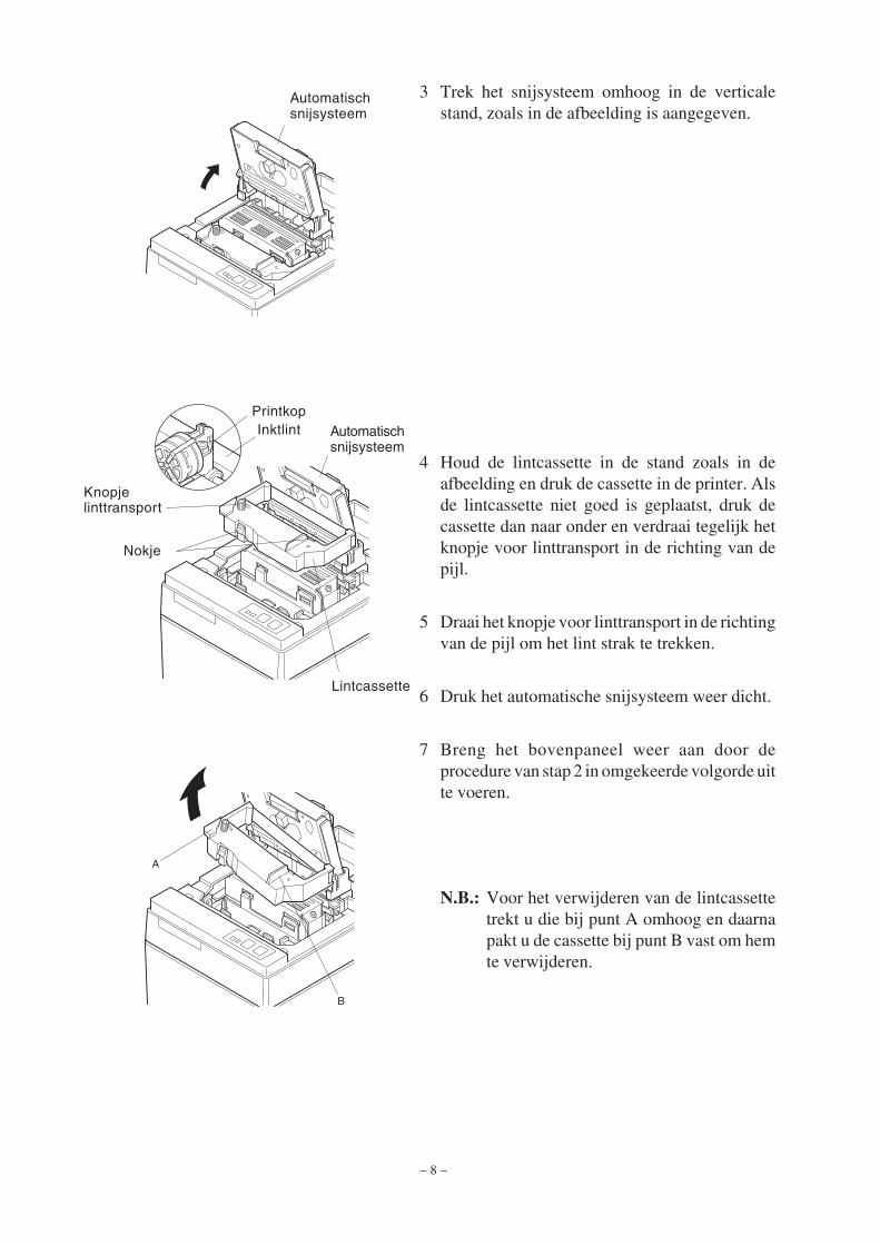
– 8 –
4 Houd de lintcassette in de stand zoals in deafbeelding en druk de cassette in de printer. Alsde lintcassette niet goed is geplaatst, druk decassette dan naar onder en verdraai tegelijk hetknopje voor linttransport in de richting van depijl.
5 Draai het knopje voor linttransport in de richtingvan de pijl om het lint strak te trekken.
6 Druk het automatische snijsysteem weer dicht.
7 Breng het bovenpaneel weer aan door deprocedure van stap 2 in omgekeerde volgorde uitte voeren.
N.B.: Voor het verwijderen van de lintcassettetrekt u die bij punt A omhoog en daarnapakt u de cassette bij punt B vast om hemte verwijderen.
A
B
3 Trek het snijsysteem omhoog in de verticalestand, zoals in de afbeelding is aangegeven.
Automatischsnijsysteem
PrintkopInktlint Automatisch
snijsysteem
Knopjelinttransport
Nokje
Lintcassette

– 9 –
Papier laden (model met scheurrand)
1 Trek het bovenpaneel ongeveer 3 cm omhoog.Houd het paneel in die stand en trek het naar u toeom het los te maken.
2 Snij de voorrand van de papierrol loodrecht af.
3 Controleer of de voeding van de printer isingeschakeld.
4 Let op de afrolrichting van de papierrol en druk hetboveneinde van het papier zo ver mogelijk onder depapiergeleider, tot het stokt. Als de papierrol correctis bevestigd, dan komt het boveneinde van hetpapier automatisch uit de papieruitvoer.
5 Druk de papierrolhouder in de richting van depijl en plaats de papierrol zodanig dat deopeningen in de kern zijn uitgelijnd met de assenvan de houder. Laat de houder weer los, zodat depapierrol wordt geborgd.
6 Als de kern van de papierrol niet correct op dehouder is uitgelijnd, dan sluit het bovenpaneelniet goed. Corrigeer dan eerst de positie van depapierrol.
7 Druk op de FEED-schakelaar (papierdoorvoer) omhet papier ongeveer 10 cm door te voeren.
8 Steek de bovenrand van het papier in de openingmet de scheurrand. Sluit het bovenpaneel door deprocedure in stap 1 hierboven in omgekeerdevolgorde uit te voeren.
N.B.: Als de markering voor het einde van depapierrol verschijnt, vervang dan de papierrolvoordat die echt op is.
Bovenpaneel
FEED-schakelaar
Papierrol
Kern
Asje
Papierrolhouder
Papierrol
BovenpaneelPositioneringsstrip
Papierrolhouder
Scheurrand
FEED-schakelaar

– 10 –
2 Snij de voorrand van de papierrol loodrecht af.3 Controleer of de voeding van de printer is
ingeschakeld.4 Let op de afrolrichting van de papierrol en druk het
boveneinde van het papier zo ver mogelijk onder depapiergeleider, tot het stokt. Als de papierrol correctis bevestigd, dan komt het boveneinde van hetpapier automatisch uit de papieruitvoer. Zodra hetpapier 2 cm uitsteekt, wordt het automatischafgesneden.
5 Druk de papierrolhouder in de richting van depijl en plaats de papierrol zodanig dat deopeningen in de kern zijn uitgelijnd met de assenvan de houder. Laat de houder weer los, zodat depapierrol wordt geborgd.
6 Als de kern van de papierrol niet correct op dehouder is uitgelijnd, dan sluit het bovenpaneelniet goed. Corrigeer dan eerst de positie van depapierrol.
7 Druk op de FEED-schakelaar (papierdoorvoer)om het papier ongeveer 10 cm door te voeren.
Papier laden (Model met automatisch snijsysteem)
1 Trek het bovenpaneel ongeveer 3 cm omhoog.Houd het paneel in die stand en trek het naar u toeom het los te maken.
Bovenpaneel
FEED-schakelaar
Papierrol
Kern
Asje
Papierrolhouder
Papierrol
BovenpaneelPositioneringsstrip
Papierrolhouder

– 11 –
9 Trek aan het papieruiteinde tot het strak staat endruk het snijsysteem naar beneden.
10 Steek het papier door de papieruitvoer en brenghet bovenpaneel weer aan door de stappen voorhet verwijderen in omgekeerde volgorde uit tevoeren.
N.B.: Als de markering voor het einde van depapierrol verschijnt, vervang dan de papierrolvoordat die echt op is.
8 Steek het papieruiteinde in de spleet van hetsnijsysteem.
• Gebruikt u kopieerpapier, steek dan alleen hetorigineel (bovenste papier) in de spleet van hetsnijsysteem. Steek het uiteinde van hetkopieerpapier (onderste) tussen de plaat en hetsnijsysteem.
AutomatischsnijsysteemPapier-
spleet
Bovenste papier
FEED-schakelaar
Printkop
Papierspleet
Plaat
Onderstepapier
Printkop Plaat
Onderstepapier
Bovenstepapier
Automatischsnijsysteem
Papieruitvoer
Automatischsnijsysteem
Papierspleet
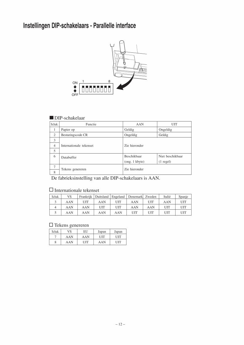
– 12 –
Instellingen DIP-schakelaars - Parallelle interface
DIP-schakelaarSchak. Functie AAN UIT
1 Papier op Geldig Ongeldig
2 Besturingscode CR Ongeldig Geldig
3
4 Internationale tekenset Zie hieronder
5
6 Databuffer Beschikbaar Niet beschikbaar
(ong. 1 kbyte) (1 regel)
7Tekens genereren Zie hieronder
8
De fabrieksinstelling van alle DIP-schakelaars is AAN.
Internationale tekensetSchak. VS Frankrijk Duitsland Engeland Denemark. Zweden Italië Spanje
3 AAN UIT AAN UIT AAN UIT AAN UIT
4 AAN AAN UIT UIT AAN AAN UIT UIT
5 AAN AAN AAN AAN UIT UIT UIT UIT
Tekens genererenSchak. VS EU Japan Japan
7 AAN AAN UIT UIT
8 AAN UIT AAN UIT
81ON
OFF

– 13 –
Instellingen DIP-schakelaars - Seriële interface
DIP-schakelaarSchak. Functie AAN UIT
1 Commandomodus STAR-commando’s VeriFone-commando’s
2 Besturingscode CR Ongeldig Geldig
3
4 Internationale tekenset Zie hieronder
5
6Datasnelheid Zie hieronder
7
8 Databit 8 databits 7 databits
9 Pariteitscontrole Nee Ja
10 Pariteit Oneven Even
De fabrieksinstelling van alle DIP-schakelaars is AAN.
Internationale tekensetSchak. VS Frankrijk Duitsland Engeland Denemark. Zweden Italië Spanje
3 AAN UIT AAN UIT AAN UIT AAN UIT
4 AAN AAN UIT UIT AAN AAN UIT UIT
5 AAN AAN AAN AAN UIT UIT UIT UIT
101ON
OFF
Datasnelheid (baud rate)Baud rate Schakelaar 6 Schakelaar 7
1200 UIT UIT
2400 UIT AAN
4800 AAN UIT
9600 AAN AAN
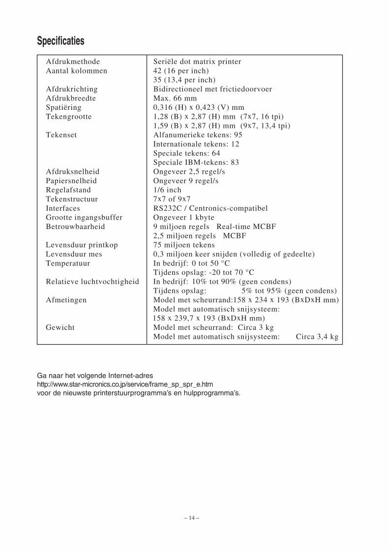
– 14 –
Afdrukmethode Seriële dot matrix printerAantal kolommen 42 (16 per inch)
35 (13,4 per inch)Afdrukrichting Bidirectioneel met frictiedoorvoerAfdrukbreedte Max. 66 mmSpatiëring 0,316 (H) x 0,423 (V) mmTekengrootte 1,28 (B) x 2,87 (H) mm (7x7, 16 tpi)
1,59 (B) x 2,87 (H) mm (9x7, 13,4 tpi)Tekenset Alfanumerieke tekens: 95
Internationale tekens: 12Speciale tekens: 64Speciale IBM-tekens: 83
Afdruksnelheid Ongeveer 2,5 regel/sPapiersnelheid Ongeveer 9 regel/sRegelafstand 1/6 inchTekenstructuur 7x7 of 9x7Interfaces RS232C / Centronics-compatibelGrootte ingangsbuffer Ongeveer 1 kbyteBetrouwbaarheid 9 miljoen regels Real-time MCBF
2,5 miljoen regels MCBFLevensduur printkop 75 miljoen tekensLevensduur mes 0,3 miljoen keer snijden (volledig of gedeelte)Temperatuur In bedrijf: 0 tot 50 °C
Tijdens opslag: -20 tot 70 °CRelatieve luchtvochtigheid In bedrijf: 10% tot 90% (geen condens)
Tijdens opslag: 5% tot 95% (geen condens)Afmetingen Model met scheurrand:158 x 234 x 193 (BxDxH mm)
Model met automatisch snijsysteem: 158 x 239,7 x 193 (BxDxH mm)
Gewicht Model met scheurrand: Circa 3 kgModel met automatisch snijsysteem: Circa 3,4 kg
Specificaties
Ga naar het volgende Internet-adreshttp://www.star-micronics.co.jp/service/frame_sp_spr_e.htmvoor de nieuwste printerstuurprogramma’s en hulpprogramma’s.

�����
������������
������������
������������� ����
�����
�������������� ���� ���������������������������� ����� ���������
���������������� ��� ������ ������������������������������������� ������������������������������������������������������������������������������������������������������������� ���������������������� ����� � �!���� �������� ������������������"����������#������������������� ��������� ��������������������������"������������� ������������ ���������� ����������������� ��������� ��������#���������� � � ������ ���������������������"������$�� ������������������� ������������������������ ���%���������� � � ������ ����������������������������������#��� �� ��#��������������� ���� ����������� ��� �� ���
&��������������������������� ������������������ �����������������! �������� �������������������������������������������� ��������������������������������������������� ���������������
�������������������� ����������� ����� ������������� ���� �����
������� ���������������������������������������������� ��������� �����������������������������'������������������� ����������������(�� ��� ����������"���
������������������ ����� ���������������� �������������� ������������������������������� ����������� ����� ������������������������������������������ �������� ����������������� ������������������������������� ��������� �����
������������������������� ��������������������������������� ���������
���������� ��� ������������������������������
��������������������������������� ��!�"��#�$%�&���!���������������������� �������������������������������������� ���������)*�+�,,,-+-./�,�0,,���)*���,01/
,2�23���������#������������������ ���)��" ���(���� "�4���� �� 5�6��" ������#�%�����)���������������"�����������232��������
���������������������'��(������������������� �((!�"�)�$%�&���!���������������������� �������������������������������������� ���������)*�+,2�,���������#�������������
���� ���7�8�9�� ����6��" ������#�%�����)���������������"������������22.��������������������������������� ���������������������������������������������������
��*�+���,�%������$�-������%"����� �!"":�; ���("���"��4����7 ��� �#�$ :�;����)�����4������ ��
�%)�.��%· ;�������������#����<�������"����������������������������������������������������������� ����������� ��
���������� �� ���;=�<�· ;���#����������������������#���������������������� !������������· $��#���������������������������������������� ����� �����#�������������������� ���� ������������ ����
����������������� ���� ����������������� ���� �� ���;=�<��������������!�������������� ����������� ��· $�����%����������������������;=�<������!��%���������������������� ������������������ �������������#�������
��������������
��4��5��! �0,,.�; ���("���"��4����7=6�

�����
�����
>����������#"�����������
��������� ������ ���
������
������������������������������� ������������������ �����!��������������������������
��������������������������
������
����������������������"��������!���������������������"��������������� �����������������������
��������#� �������������������
$��!��#������%������������%������������������������������!������������������� ������
����� %�&��������� ����������!��������"����������
����� ����������������%������&'
���� ���������������������������� ��"������� ���������������������������������� ��������� ���������� �������������� ����������� ��� �������

�����
��� �� �� �� � �
�� ������� � ��� �
'��������� ����� ���������� ������������������� �������� ���� �������������������� ������ ��'� ������ ��������������%��������"��
✓ ������ ������ ������������!������������������%��� ����#�������"�����
✓ *���������� ��"���������������� ������ � ����������������� ���������� �������� �����
✓ $���� �������������������������������������������������������#�� �������� �
✓ $���� ��������������������#������������������������ ���✓ $���� �������������������������������� ��������� ���������!����#�!������
������
✓ $���� ����������������������������� �����!�� ������������ ������
✓ $���� ������������������������������������������������� ��"���*��� ��� ��"������������� ������������� ��������������!������"������������������������������ ����#���� �������������
✓ $���� ������������ ����������������� �������������� �����#���
✓ '���✓ ���������������✓ '���������✓ ��� ����������?�������)$@✓ ;�����?�������)$@
'���
�������������� $��#����� �����
��� ����������?�������)$@
;�����?�������)$@

�����
��������� ���� �
������������� ������ �� ������ ������������� ���� ����������������������������������"���"�����
?�@�;��"���"����������������9�� �������: ��������������������������������A���������: B+C,������?.�,����@'�����������: ���� ��3�����?.�.�����@>� ����������������: ��0C����
$��� �(�'������������� ���������������������������6������:�(����������� �������� �������?������ ���@�B,�'������,,�'�
?���������@��������D�0�������?���� ��0,,�'�@������������������(��������� ��� ������������?������ ���@�B,�'������,,�'�
?���������@��������D��������?���� ���,,�'�@$��� �(��� ��� ����������������������������
������ ���������������������������������,,�'�������������������������������������������������������������������������������,�'���&�����������������%������,,�'���������%������ ����������� ��� ������������
?0@�;��"���"��� ������� � ��9�� �� ����: ��� ����#��E���: ��� ��;'0�0/010:�����������?�����������"��������@
��� ��;'0�+/01+:���������?"�����"����������@(� ������ ����: *������++�?F1,������@9���� ����: G���������:
��������:�.�,,,�,,,��������"���:���0,,�,,,��������6�������:4��������������� ����:�+,,�,,,��������4����������������� ����:�.,,�,,,��������

�����
��� ��� �� ����
) �����*�7>*)(������� ��������������*�7>*)�������7>*)����� ����'����"������������ ������*�7>*)�����7>*)�����%��������������������������� �� �����
* �����))6H '� ������������ ������������� �������������
���������,��������������������������"���H '� ��������#���������� �������������,�����
����������������� �������?�������������������������������%�������*�7>*)������7>*)�� ������������@
+ 7���"��'�I)<�?�����������@H ;��� ������������������������������������������H E��� ���������������������������������!����������� �����������������������������
��������� ������ ����������������������������� ���4'$-��H ������������ �������������� � �������������� �� �� �����*�7>*)�H ��������"��'�I)<����������������!�������� � ��%��������� �������������� ���� �
�������� � ��%�� ��������������� ������������������� ������ ���������H ��������"��'�I)<��������������������������������������� ������ ����������������%����
�� ��� ��������� �������� ������ ��������������
, 7���"���*�7>*)�?�����������@7���"������ �:�'��������*�7>*)7���"��������� �:�'�����������7>*)7���"���������:������ ���4'$-�
��������"��'�I)<���*�7>*)�� ����������� ������ �������������� ���4'$-��
��� ������� ��� ������������ ����� ����� ��
) >������ ������������������
* '���� ���������"�� �����.�"���&���# �������� ���� �������� ���������" ���������������� ������������
'������"
>������������������
ON LINEPOWER FEED
3 - NAPAJANJE (zelena LED dioda)
4 - ON LINE (zelena LED dioda)
1- ON LINE prekidaè
2 - FEED prekidaè

����
A
B
+ $��#����� ��������� �� ��������#���������������"� ����������� ��������������� ������� ������������#����� ��������������������������� ����� �� ���������%�%������������ ����� ������������������������ ���"���
, ����% �������������� ����� ������������������������ ���"���������� �������� �����
- 9�� ���������"���� ���������� ���������������������������*�
$��� �(�'���������������� ����� ���������� ������������ ������� �����#������#�����%����E������ ������������������"�
��� ������� ��� ��������� ���� ������� ��
) >������ ������������������
* '���� ���������"�� ������.�"���&���# �������� ���� �������� ���������" ���������������� ������������
>�����������
=������ � ��
J���������� ���� ����
6���� ����
$��#����� �����
'������"
>������������������

����
A
B
, $��#����� ��������� �� ��������#���������������"� ����������� ��������������� ������� ������������#����� ��������������������������� ����� �� ���������%�%������������ ����� ������������������������ ���"���
- ����% �������������� ����� ������������������������ ���"���������� �������� �����
! ;��� ���� ��� ���������
. 9�� ���������"���� ���������� ���������������������������*�
$��� �( '���������������� ����� ���������� ������������ ������� ����#�������#�����%����E������ ������������������"�
+ '���� ���� ��� ������������� �� ���������� �����#�������� �������������������"�
�� ��� �������
>�����������=������ � �� �� ��� ��
�����
J���������� ����� ����
6����� ����
$��#���� �����

�����
��� ��� ��� ��������� ����� ����� ��
) '���� ���������"�� ������.�"���&���# �������� ���� �������� ���������" ���������������� ������������
* '�������������# �����������������������
+ $���� �������������������������������������
, >����%����������������� ������������������� � ������%��������������������"��������������������#� ������������������������� �� �������%�%�������������� ��� �����%������������������
- '����� ����#������������������ ���"����� � ������� ����������� ��������������������������������������������#�����'�� ���#�������������������� �������
! ���������������������������������������� �����#��������%� ����%������������� �������"����������������� ������#���������
. '� �� �� �����))6�?���������������@������ �������� �������,�"��������
/ 9���%�������������� � ��������������� ������ ������������ ����� ���������"���� ��������� ����������������������������)�
$��� �( ���������������������������������������������� ���������������� ������������� ����������
'������"
����))6
'���������*���������
��
6�#�������������
'���������
'������"
<����������"�������
6�#�������������
6��� ������� ������
�����))6

������
* '�������������# �����������������������+ $���� �������������������������������������, >����%����������������� ����������������
��� � ������%��������������������"��������������������#� ������������������������� �� �������%�%�������������� ��� �����%�������������������������������������0�"�������� ���%������ ��� ��� �����������
- '����� ����#������������������ ���"����� � ������� ����������� ��������������������������������������������#�����'�� ���#�������������������� �������
! ���������������������������������������� �����#��������%� ����%������������� �������"����������������� ������#���������
. '� �� �� �����))6�?���������������@����� ��������� �������,�"��������
��� ��� ��� ������ ���� ������� ��
) '���� ���������"�� ������.�"���&���# �������� ���� �������� ���������" ���������������� ������������
'������"
����))6
'���������
*���������
��
6�#�������������
'���������
'������"<����������"�������
6�#�������������

������
0 '���" ������������������� ���� ��������������� ������ ���� ��� ���������
)"$�� � �������������������������� ���������"�������%����� ��������������������������� ������������
$��� �( ���������������������������������������������� ����������������� ������������ ����������
/ $�� � ����!����������������������� ��� �����������
�������� �������������%����������������� ��� ��������������� � �������������?���������������@��'�������������%����� ��� ������?���������@���� � �����������"���� ��� ������������
��� ��� �������'��������
��� ���������
J���������������
�����))6
>�����������
'����������� ����������
'���"�
6�������������
>����������
'���"�
6�������������
J��������������
�� ��� �������
>������������
�� ��� �������
'����������� ����������

������
81ON
OFF
���� ��!������� � "������ � �����������
����6>'-�������'������ ����"�� $�7G$K)* >;�7G$K)*
� ��6� ��"������ ���������� 9�#�%� *���#�%�
0 ����� ������L��4< *���#�% 9�#�%
.
1 ��(��������������������� 9�������
�
+ ��'��� ��������������� 6�� ���� *���� ����
?�������E@ ?������@
B��'�� ����������������������� 9�������
3
$� ��������������� ������6>'������������ �������������#���M���������N�
���(���������������������'������ ;�6 ����"���� *������� )������� 6����� A������ > ���� A���������
. $�7G$K)* >;�7G$K)* $�7G$K)* >;�7G$K)* $�7G$K)* >;�7G$K)* $�7G$K)* >;�7G$K)*
1 $�7G$K)* $�7G$K)* >;�7G$K)* >;�7G$K)* $�7G$K)* $�7G$K)* >;�7G$K)* >;�7G$K)*
� $�7G$K)* $�7G$K)* $�7G$K)* $�7G$K)* >;�7G$K)* >;�7G$K)* >;�7G$K)* >;�7G$K)*
���J�����������������'������ ;�6 )$ G' G'
B $�7G$K)* $�7G$K)* >;�7G$K)* >;�7G$K)*
3 $�7G$K)* >;�7G$K)* $�7G$K)* >;�7G$K)*

������
���� ��!������� � "����� ��������������
����6>'-�������'������ ����"�� $�7G$K)* >;�7G$K)*
� ��*�������������������� ;=�<����� 9�����������
0 ����� ������L��4< *���#�% 9�#�%
.
1 ��(��������������������� 9�������
�
+��E������������������ ��� 9�������
B
3 ��E�������� ����!�� � 3�� � B�� �
2 ��'����������� � � *� 6�
�, ��'�� � *����� '���
$� ��������������� ������6>'������������ �������������#���O���������P�
���(���������������������'������ ;�6 ����"���� *������� )������� 6����� A������ > ���� A���������
. $�7G$K)* >;�7G$K)* $�7G$K)* >;�7G$K)* $�7G$K)* >;�7G$K)* $�7G$K)* >;�7G$K)*
1 $�7G$K)* $�7G$K)* >;�7G$K)* >;�7G$K)* $�7G$K)* $�7G$K)* >;�7G$K)* >;�7G$K)*
� $�7G$K)* $�7G$K)* $�7G$K)* $�7G$K)* >;�7G$K)* >;�7G$K)* >;�7G$K)* >;�7G$K)*
101ON
OFF
����E������������������ ����?��������@E������������"�� '�������+ '�������B
�0,, >;�7G$K)* >;�7G$K)*
01,, >;�7G$K)* $�7G$K)*
13,, $�7G$K)* >;�7G$K)*
2+,, $�7G$K)* $�7G$K)*
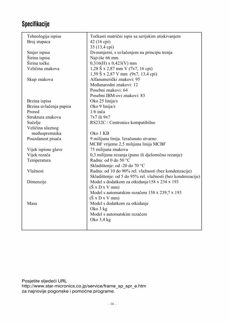
������
=�!������������ =����� ��� �������������������� ��������E����� ���"� 10�?�+�"�@
.��?�.�1�"�@;��������� 6�����������������������������"��� �����A�������� *��� ��++���A���� ���� ,�.�+?Q@�R�,�10.?9@���9������������� ��03�A�R�0�3B����9�?BRB���+�"�@
���2�A�R�0�3B�9�����?2RB���.�1�"�@;����������� ������������������:�2�
(���������������:��0'������������:�+1'������>E(-���������:�3.
E��������� ����0������/�E�������������������� ����2�����/�'����� �/+����; ��� ����������� BRB���2RB;������ <;0.04�/�4�� ���"������� ����9���������������������������� �������E'�������� ������ 2��������������>������� ��� �����
�(4E���������0���������������(4E�9��������������� B����������������9���������� ,�.����������������?������������������������@=������ ��� <����:����,�����,�S4
;���� ����:����-0,����B,�S49��#��� <����:�����,����2,T���������#��� �?������������"��@
;���� ����:���������2�T���������#��� �?������������"��@6������ (����������� �������� ��������3�R�0.1�R��2.
�?A�R�6�R�9���@(��������� ��� ��������������3�R�0.2�B�R��2.�?A�R�6�R�9���@
(��� (����������� �������� ����������.���(��������� ��� ���������������.�1���
������� ���
������������������ ������������������������������������������������������������������������������ ���������������������

– 1 –
МАТРИЧНЫЕ ПРИНТЕРЫМАТРИЧНЫЕ ПРИНТЕРЫМАТРИЧНЫЕ ПРИНТЕРЫМАТРИЧНЫЕ ПРИНТЕРЫМАТРИЧНЫЕ ПРИНТЕРЫ
СЕРИИ SP200
РУКОВОДСТВОПОЛЬЗОВАТЕЛЯ

– 2 –
Федеральная комиссия по связи (FCC)Заявление
о радиочастотных помехах
Данное устройство было протестировано, и проверка показала, что оно соответствует требованиям,предъявляемым к цифровым устройствам класса А, изложенным в части 15 правил FCC. Эти требованияпредназначены для того, чтобы прочее оборудование было защищено от помех при работе с устройством впромышленной среде. Данное устройство генерирует, использует и может излучать радиочастотную энергию,поэтому нарушение правил настоящего руководства при установке и использовании устройства может повлечьза собой создание помех средствам радиосвязи. Работа данного устройства в жилом районе может создатьрадиопомехи, которые должны быть устранены за счет пользователя.Для соответствия Федеральному стандарту по шумовым помехам в данном устройстве должен использоватьсяэкранированный кабель.Настоящее заявление относится только к принтерам, продаваемым на территории США.
Заявлениеканадского департамента по вопросам коммуникаций
Требования к радиопомехам
Уровень помех, создаваемых данным цифровым устройством, не превышает предельных значенийинтенсивности шумового радиоизлучения для цифровых устройств, установленных в рамках требований крадиопомехам канадского департамента по вопросам коммуникаций.Le presént appareil numérique n’émet pas de bruits radioélectriques dépassant les limites applicables aux appareils numériques de laclasse A prescrites dans le Règlement sur le brouillage radioélectrique èdictè par le ministé re des Communications du Canada.Настоящее заявление относится только к принтерам, продаваемым на территории Канады.
CEДекларация производителя о соответствии требованиям
Директива Совета ЕС № 89/336/EEC от 3 мая 1989 г.Данный продукт был разработан и изготовлен в соответствии с международными стандартами EN 61000(6(3/10.2001 и EN 55024(1/09.98 с учетом предписаний Директивы по электромагнитной совместимостиЕвропейского экономического сообщества от мая 1989 г.
Директивы Совета ЕС № 73/23/EEC и 93/68/EEC от 22 июля 1993 г.Данный продукт был разработан и изготовлен в соответствии с международными стандартами EN 60950 сучетом предписаний Директивы по низковольтным устройствам Европейского экономического сообществаот июля 1993 г.Настоящее заявление относится только к принтерам, продаваемым на территории ЕС.
Информация об обладателях товарных знаковSP200: Star Micronics Co., Ltd.ESC/POS: Seiko Epson Corporation
Примечание· Все права защищены. Запрещается воспроизводить любую часть данного руководства в какой бы то ни
было форме без явного разрешения компании STAR.· Содержание данного руководства может быть изменено без предварительного уведомления.· Были предприняты все меры к тому, чтобы обеспечить корректность содержания данного руководства
на момент его отправки в печать. Однако компания STAR будет очень признательна за сообщения олюбых ошибках, если таковые будут обнаружены.
· Несмотря на вышесказанное, компания STAR не несет никакой ответственности за любые ошибки вданном руководстве.
© Copyright 2003 Star Micronics Co., LTD.

– 3 –
Информация по технике безопасности
Важные сведения!Перед подключением устройства убедитесь, что принтер выключен и отсоединен от сетипеременного тока, а также выключен компьютер.
Важные сведения!Не подключайте кабель телефонной линии к разъему, предназначенному для дополнительногодиска. В противном случае принтер может выйти из строя.Кроме того, в целях безопасности нельзя подключать к разъему для внешнего диска кабели,если есть вероятность, что разъем находится под напряжением.
Подключение кабеля заземления (только для стран ЕС)Вывинтите винт, показанный на рисунке, затем приложите наконечник кабеля заземленияк тому месту, откуда был снят винт, и вновь затяните винт.
Кабель
Отдельныйкабельзаземления

– 4 –
Распаковка принтера
Выбор места для установки принтераПрежде чем распаковывать принтер, уделите несколько минут тому, чтобыподумать, где его лучше установить. При этом рекомендуем учесть следующиесоветы:
· Выбирайте твердую, ровную поверхность, на которой принтер не будетвибрировать.
· Розетка, которую Вы собираетесь использовать, должна находиться рядом сместом установки, и доступ к ней должна быть свободен.
· Не ставьте принтер далеко от компьютера, к которому он будет подключен.· На принтер не должен попадать прямой солнечный свет.· Не устанавливайте принтер вблизи нагревателей и других источников тепла.· Убедитесь, что вокруг нет грязи, везде сухо и нет пыли.· Принтер необходимо подключать к исправной сетевой розетке. Не
рекомендуется подключать устройство к одной электролинии с копирами,холодильниками и другими приборами, способными вызвать перепады внапряжении.
· В комнате, где находится принтер, не должно быть повышенной влажности.
· Принтер· Руководство пользователя· Картридж с лентой· Ферритовый сердечник (только в странах ЕС)· Соединитель (только для стран ЕС)
Принтер
Руководствопользователя Картридж с
лентой
Ферритовыйсердечник (только в
странах ЕС)
Соединитель(только длястран ЕС)

– 5 –
Расходные материалы
Для замены расходных материалов используйте только те, что указаны в приведеннойниже таблице.
(1) Характеристики рулонной бумагиТип бумаги: Обычная высококачественная бескопирочная
копировальная бумагаШирина бумаги: 76±0,5 мм (3,0 дюйма)Диаметр рулона: ∅ 85 мм (3,35 дюйма) макс.Внутренний диаметррулона: ∅ 12±1 мм
Примечание: Бумага не должна быть приклеена ксердечнику.
Плотность: Модель с отрывной планкой(один экземпляр) 70 г/м2 – 100 г/м2
(копии) оригинал + 2 копии (макс. 200 г/м2) Модель с автоматическим резаком
(один экземпляр) 70 г/м2 – 100 г/м2
(копии) оригинал +1 копии (макс. 100 г/м2)Примечание: Автоматический резак
рассчитан на бумагу плотностью не более100 г/м2. Такая плотность соответствуетне более чем двум листам бумагиплотностью по 50 г/м2 каждый .Применение бумаги плотностью более100 г/м2 может привести к неправильномуотрезанию.
(2) Характеристики красящей лентыТип ленты: КартриджЦвет: SP212/242: Одноцветная (фиолетовая или черная)
SP212/246: Двухцветная (черно(красная)Материал ленты: Нейлон 66 (плотность – 40 денье)Ресурс ленты: Одноцветная:
Фиолетовая – 3 000 000 символовЧерная – 1 200 000 символовДвухцветная:Черный сегмент – 600 000 символовКрасный сегмент – 300 000 символов

– 6 –
Панель управления
� Переключатель ON LINEПереключает принтер между режимами ON LINE(установлена связь с компьютером) и OFF LINE(связь с компьютером отключена). Переключениемежду режимами ON LINE и OFF LINE возможнотолько при наличии бумаги в принтере.
� Кнопка FEED• Эта кнопка предназначена для подачи бумаги.
Кратковременное нажатие (длительностью до0,5 с) приводит к подаче бумаги на 1 строку.
• Длительное нажатие (более 0,5 с) приводит кнепрерывной подаче бумаги.Кнопка подачи работает как в режиме ON LINE,так и в режиме OFF LINE.
� Индикатор POWER (питание) – зеленый светодиод• Горит, когда включено питание принтера.• Мигает, когда в принтере нет бумаги, при возникновении механического повреждения,
при перегреве, а также при возникновении ошибки в процессоре.• Если в принтере нет бумаги, загрузите новую бумагу и нажмите кнопку ON LINE.• Если индикатор POWER мигает из(за механического повреждения, отключите питание
принтера, устраните причину механического повреждения и вновь включите питание.• Если индикатор POWER мигает из(за перегрева головки, принтер автоматически
продолжит работу после того, как головка остынет.
� Индикатор ON LINE – зеленый светодиодГорит: Принтер работает в режиме ON LINE (на связи с компьютером)Не горит: Принтер работает в режиме OFF LINE (связь с компьютером разорвана)Мигает: Ошибка процессора
Одновременное мигание индикаторов POWER и ON LINE сигнализирует об ошибкепроцессора.
Установка картриджа с лентой (модель с отрывной планкой)
� Отключите питание принтера.
� Поднимите крышку на высоту около 3 см.Придерживая крышку под таким углом,потяните ее на себя и снимите.
Крышка
Отключитепитание!
ON LINEPOWER FEED
3 POWER lamp (Green LED)
4 ON LINE lamp (Green LED)
1 ON LINE switch
2 FEED switch� Кнопка FEED –подача бумаги
� Индикатор POWER (питание) –зеленый светодиод
� Индикатор ONLINE (на связи) –зеленый светодиод
� Кнопка ONLINE (на связи)

– 7 –
� Установите картридж с лентой, какпоказано на иллюстрации, и нажмитеего вниз для фиксации. Если послезагрузки картриджа лента провисла,поверните рукоятку подачи лентыв направлении стрелки.
� Поворачивайте рукоятку до тех пор,пока провисание не будет устранено.
� Установите крышку в порядке,обратном описанному на шаге 2.
Примечание: Для того чтобы снятькартридж, нужно поднять сторону A,а затем снять картридж, придерживаяза сторону B.
Установка картриджа с лентой (модель савтоматическимрезаком)
� Отключите питание принтера.
� Поднимите крышку на высоту около3 см. Придерживая крышку под такимуглом, потяните ее на себя и снимите.
Головка
Лента
Подачаленты
Вырезы
Картриджс лентой
A
B
Отключитепитание!
Крышка

– 8 –
� Установите картридж с лентой, какпоказано на иллюстрации, и нажмитеего вниз для фиксации. Если послезагрузки картриджа лента провисла,поверните рукоятку подачи лентыв направлении стрелки.
� Поворачивайте рукоятку до тех пор,пока провисание не будет устранено.
� Закройте автоматический резак.
� Установите крышку в порядке, обратномописанному на шаге 2.
Примечание: Для того чтобы снятькартридж, нужно поднять сторонуA, а затем снять картридж,придерживая за сторону B.
A
B
� Поднимите резак и оставьте егов вертикальном положении, какпоказано на рисунке.
Резак
Головка
Красящаялента Резак
Рукояткаподачиленты
Вырезы
Картридж слентой

– 9 –
Загрузка бумаги (модель с отрывной планкой)
� Поднимите крышку примерно на 3 см.Придерживая крышку в этомположении, потяните ее на себяи снимите.
� Обрежьте конец ленты так, чтобы онстал прямым.
� Убедитесь в том, что включено питаниепринтера.
� Вставьте конец ленты в направляющиеи засуньте его как можно глубже,соблюдая при этом правильнуюориентацию рулона. При установкерулонной бумаги конец рулона покажетсяиз выходного отверстия.
� Переместите держатель рулонав направлении стрелки и установитерулон таким образом, чтобы отверстияв сердечнике соответствовали осямдержателя. Отпустите держатель рулонадля фиксации бумаги.
� Выровняйте сердечник рулона поотношению к держателю, т.к.в противном случае не удастсяправильно закрыть крышку.
� С помощью кнопки FEED (подачабумаги) подайте около 10 см бумаги.
� Вставьте конец рулона в щель отрывнойпланки, затем закройте крышкув порядке, обратном описанному на шаге1 выше.
Примечание: Заменяйте рулон сразуже, как только на бумаге покажетсямаркер конца рулона. Недожидайтесь, пока рулон полностьюзакончится.
Крышка
КнопкаFEED
Рулоннаябумага
Сердечник
Ось
Держательрулона
Рулоннаябумага
КрышкаНаправляющая
Держатель рулона
Отрывнаяпланка
КнопкаFEED

– 10 –
� Обрежьте конец ленты так, чтобы онстал прямым.
� Убедитесь в том, что включено питаниепринтера.
� Вставьте конец ленты в направляющиеи засуньте его как можно глубже,соблюдая при этом правильнуюориентацию рулона. При установкерулонной бумаги конец рулона покажетсяиз выходного отверстия. Бумагаавтоматически отрезается после выходаотрезка приблизительно на 2 см.
� Переместите держатель рулонав направлении стрелки и установитерулон таким образом, чтобы отверстияв сердечнике соответствовали осямдержателя. Отпустите держатель рулонадля фиксации бумаги.
� Выровняйте сердечник рулона поотношению к держателю, т.к.в противном случае не удастсяправильно закрыть крышку.
� С помощью кнопки FEED (подачабумаги) подайте около 10 см бумаги.
Загрузка бумаги (модель с автоматическимрезаком)
� Поднимите крышку примерно на 3 см.Придерживая крышку в этомположении, потяните ее на себяи снимите.
Крышка
КнопкаFEED
Рулоннаябумага Сердечник
Ось
Держательрулона
Рулоннаябумага
КрышкаНаправляющая
Держатель рулона

– 11 –
� Вытяните конец бумаги для того, чтобыустранить провисание, и опустите резак.
� Вставьте бумагу в выходное отверстиеи закройте крышку в обратном порядке.
Примечание: Заменяйте рулон сразуже, как только на бумаге покажетсямаркер конца рулона. Недожидайтесь, пока рулон полностьюзакончится.
� Вставьте конец рулона в автоматическийрезак.
• Если используется самокопирующаясябумага, в резак нужно помещать толькооригинал (верхний слой). Копию(нижний слой) нужно вставить междуоснованием и резаком.
Автоматическийрезак
Окнодля вставкибумаги
Верхний слой
Кнопка FEED
Печатающаяголовка
Окно длябумаги
Основа
Нижнийслой Печатающая
головка
Основа
Нижнийслой
Верхнийслой
Автоматическийрезак
Выходноеокно
Автоматическийрезак
Окно длябумаги

– 12 –
Настройка DIP&переключателей: параллельный интерфейс
DIP(переключательDIP Функция ON OFF
1 Детектор конца бумаги Вкл. Выкл.
2 Управляющий код CR Выкл. Вкл.
3
4 Международный набор символов См. ниже
5
6 Буфер данных Доступен Недоступен
(около 1 кб) (1 строка)
7Режим символьного генератора См. ниже
8
Заводское положение DIP(переключателей – все вположении ON.
Международный набор символовDIP США Франция Германия Англия Дания Швеция Италия Испания
3 ON OFF ON OFF ON OFF ON OFF
4 ON ON OFF OFF ON ON OFF OFF
5 ON ON ON ON OFF OFF OFF OFF
Символьный генераторDIP США ЕС Япония Япония
7 ON ON OFF OFF
8 ON OFF ON OFF
81ON
OFF

– 13 –
Настройка DIP&переключателей: последовательный интерфейс
DIP(переключательDIP Функция ON OFF
1 Режим команд Режим STAR Режим VeriFone
2 Управляющий код CR Выкл. Вкл.
3
4 Международный набор символов См. ниже
5
6Скорость передачи данных См. ниже
7
8 Длина данных 8 бит данных 7 бит данных
9 Проверка четности Нет Есть
10 Четность Нечетная Четная
Заводское положение DIP(переключателей – все вположении ON.
Международный набор символовDIP США Франция Германия Англия Дания Швеция Италия Испания
3 ON OFF ON OFF ON OFF ON OFF
4 ON ON OFF OFF ON ON OFF OFF
5 ON ON ON ON OFF OFF OFF OFF
101ON
OFF
Скорость передачи данныхБод Переключатель 6 Переключатель 7
1200 OFF OFF
2400 OFF ON
4800 ON OFF
9600 ON ON

– 14 –
Способ печати Последовательная ударная матричная печатьЧисло знакомест 42 (16 символов на дюйм)
35 (13,4 символа на дюйм)Направление печати Двунаправленная печать с фрикционной
подачейШирина области печати Макс. 66 ммРасстояние между точками 0,316 (гор.) × 0,423(верт.) ммРазмер символа 1,28 (ш) × 2,87 (в) мм (7×7, 16 симв./дюйм)
1,59 (ш) × 2,87 (в) мм (9×7, 13,4 симв./дюйм)Набор символов Алфавитно(цифровые символы: 95
Международные символы: 12Специальные символы: 64Специальные символы IBM: 83
Скорость печати Около 2,5 строк/сСкорость подачи бумаги Около 9 строк/сМежстрочный интервал 4,2 ммСтруктура символов 7×7 или 9×7Интерфейс Совместим с RS232C / CentronicsОбъем буфера приема Около 1 кбНаработка на отказ 9 млн. строк – экспериментальный результат
2,5 млн. строк – расчетная наработкаСрок службы головки 75 млн. символовРесурс резака 0,3 млн. разрезов (полных или частичных)Температура Эксплуатация: от 0 до 50 °C
Хранение: от (20 до 70 °CВлажность Эксплуатация: от 10 до 90 % (без конденсации)
Хранение: от 5 до 95% (без конденсации)Габариты С планкой: 158 × 234 × 193 (ш×г×в мм)
С резаком: 158 × 239,7 × 193 (ш×г×в мм)Вес С планкой: Около 3 кг
С резаком: Около 3,4 кг
Технические характеристики
На странице нашего сайта по адресуhttp://www.star�micronics.co.jp/service/frame_sp_spr_e.htmВы сможете найти информацию о новейших драйверах и утилитах для принтеров.

2004.01.15Printed in Japan, 80870370
OVERSEAS SUBSIDIARY COMPANIESSTAR MICRONICS AMERICA, INC.1150 King Georges Post Road, Edison,NJ 08837-3729 U.S.A.Tel : 732-623-5555Fax: 732-623-5590http://www.starmicronics.com
ELECTRONIC PRODUCTS DIVISIONSTAR MICRONICS CO., LTD.536 Shimizunanatsushinya,Shizuoka, 424-0066 JapanTel : 0543-47-0112Fax: 0543-48-5013
Distributed by
STAR MICRONICS EUROPE LTD.Star House, Peregrine BusinessPark, Gomm Road, High Wycombe,Bucks, HP13 7DL, U.K.Tel : 01494-471111Fax: 01494-473333http://www.StarMicronicsEurope.com
Please access the following URLhttp://www.star-micronics.co.jp/service/frame_sp_spr_e.htmfor the lastest revision of the manual.


