KEYSTONE Figure 79U/E Pneumatic Actuator models 002 to 180 Emerson reserves the right to change the contents without notice HDLDS-0006-EN-1305 Technical Data Max. supply pressure : 10 barg Rated supply pressure : 8.3 barg Output torque at 5.5 barg Double Acting models : up to 2054 Nm Spring Return models : up to 1414 Nm Temperature range : -30° to +90°C* with standard components. * An extended temperature range from -30°C to +150°C is available on request. Double Acting (air to air) and Single Acting (spring return), 90° operation, pneumatic actuators General Applications For remote control of any quarter turn application, for example Ball, Butterfly or Rotary Plug Valves, Dampers etc. Accessories An extensive range of standard accessories is available for direct mounting to Keystone actuators. - Solenoid Valves - weatherproof, explosionproof or intrinsically safe. - Limit Switchboxes - weatherproof, explosionproof or intelligent. - Positioners - pneumatic, electro- pneumatic or intelligent. - Declutchable manual override gearbox. - High Visibility Indicator. - Proximity sensing - weatherproof intrinsically safe, or intelligent. Features • Compact rack and pinion design utilising the whole piston area to develop output torque. • Pistons with integral rack drive reducing the number of dynamic seals, minimising air leakage. • Double pistons nullify sideloads on the pinion shaft, minimising bearing wear. • Springs epoxy painted and colour coded for additional corrosion protection and ease of identification. • Hard anodised aluminium body, with external ESPC finish, protects against corrosive environments including saliferous atmospheres. • Female output drive enabling direct mounting in certain applications, thereby eliminating special connections and guaranteeing correct alignment. • Bottom entry pinion shaft. • Anti-friction piston pads ensuring no metal to metal contact, providing a smooth operation. Ideal for modulating or on/off control applications. • Adjustable travel stops in both directions on certain models. • Grease lubricated for life. • ATEX certified II 2 GD. KEYSTONE www.valves.emerson.com
Transcript
KEYSTONE
Figure 79U/E Pneumatic Actuatormodels 002 to 180
Emerson reserves the right to change the contents without notice HDLDS-0006-EN-1305
Technical DataMax. supply pressure : 10 barg
Rated supply pressure : 8.3 barg
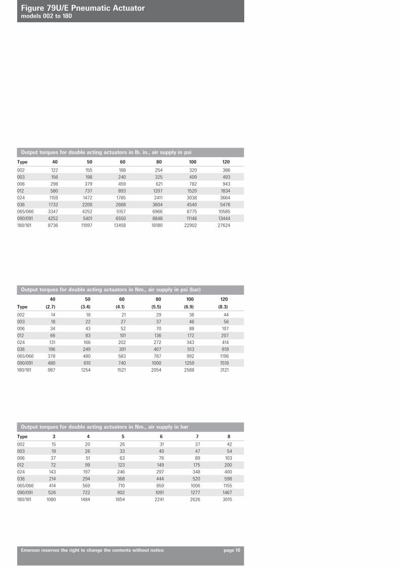
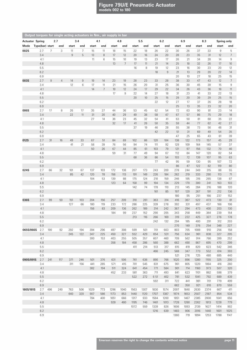
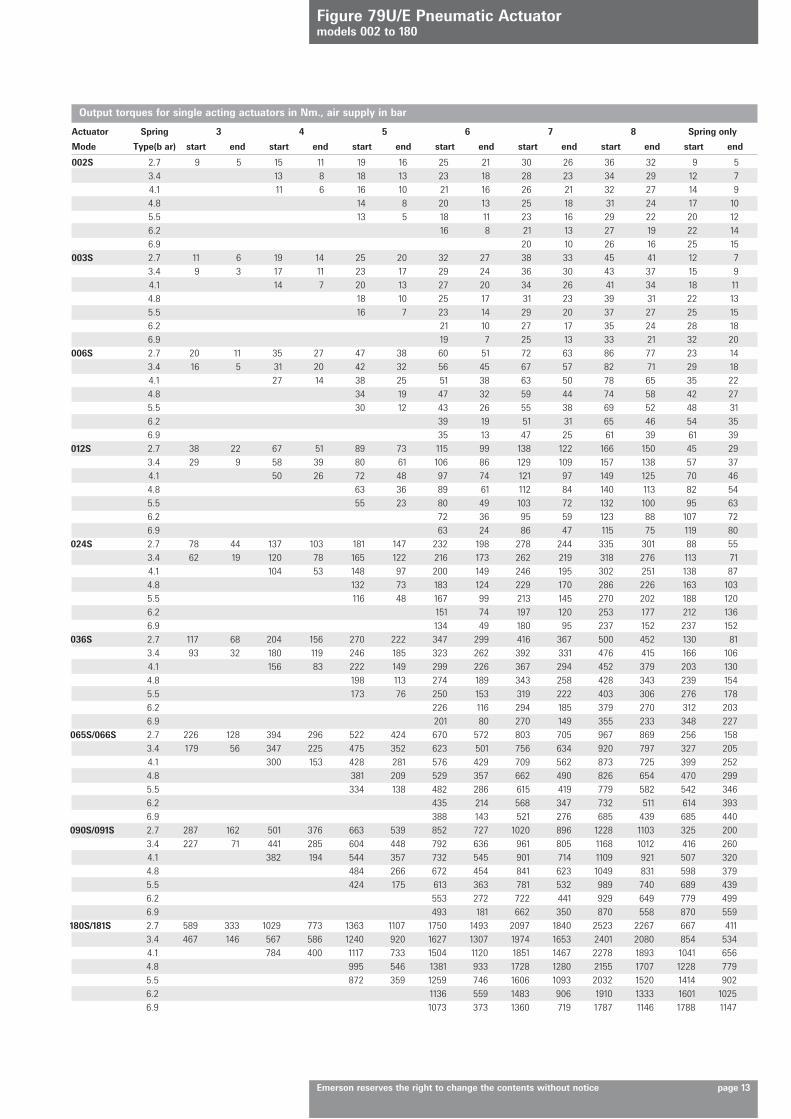
Output torque at 5.5 bargDouble Acting models : up to 2054 NmSpring Return models : up to 1414 Nm
Temperature range : -30° to +90°C* with standard components.
* An extended temperature range from -30°C to +150°C is available on request.
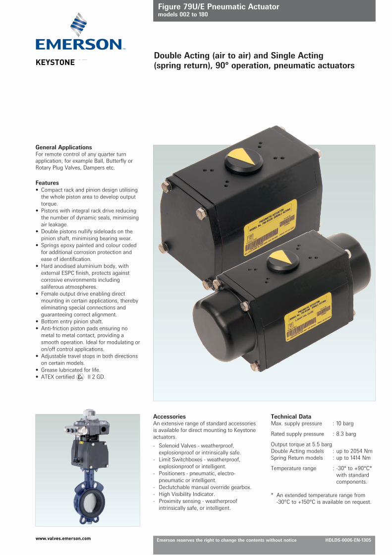
Double Acting (air to air) and Single Acting (spring return), 90° operation, pneumatic actuators
General ApplicationsFor remote control of any quarter turn application, for example Ball, Butterfly or Rotary Plug Valves, Dampers etc.
AccessoriesAn extensive range of standard accessories is available for direct mounting to Keystone actuators.
- Solenoid Valves - weatherproof, explosionproof or intrinsically safe.
- Limit Switchboxes - weatherproof, explosionproof or intelligent.
- Positioners - pneumatic, electro-pneumatic or intelligent.
Features• Compact rack and pinion design utilising
the whole piston area to develop output torque.
• Pistons with integral rack drive reducing the number of dynamic seals, minimising air leakage.
• Double pistons nullify sideloads on the pinion shaft, minimising bearing wear.
• Springs epoxy painted and colour coded for additional corrosion protection and ease of identification.
• Hard anodised aluminium body, with external ESPC finish, protects against corrosive environments including saliferous atmospheres.
• Female output drive enabling direct mounting in certain applications, thereby eliminating special connections and guaranteeing correct alignment.
• Bottom entry pinion shaft.• Anti-friction piston pads ensuring no
metal to metal contact, providing a smooth operation. Ideal for modulating or on/off control applications.
• Adjustable travel stops in both directions on certain models.
• Grease lubricated for life.• ATEX certified II 2 GD.
KEYSTONE
www.valves.emerson.com
Figure 79U/E Pneumatic Actuatormodels 002 to 180
Emerson reserves the right to change the contents without notice page 2
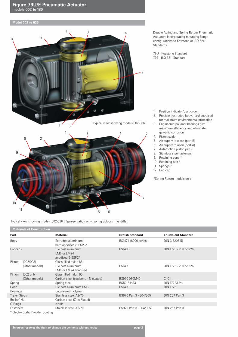
1. Position indicator/dust cover2. Precision extruded body, hard anodised
for maximum environmental protection3. Engineered polymer bearings give
maximum efficiency and eliminate galvanic corrosion
4. Piston seals5. Air supply to close (port B)6. Air supply to open (port A)7. Anti-friction piston pads8. Stainless steel fasteners9. Retaining cone *10. Retaining bolt *11. Springs *12. End cap
*Spring Return models only
Typical view showing models 002-036 (Representation only, spring colours may differ)
Double Acting and Spring Return Pneumatic Actuators incorporating mounting flange configurations to Keystone or ISO 5211 Standards.
79U - Keystone Standard79E - ISO 5211 Standard
Typical view showing models 002-036
1 3 4
7
28
5 6
1
9
10
11
3 4 12
7
28
5 6
Model 002 to 036
Materials of Construction
Part Material British Standard Equivalent Standard
Body Extruded aluminium BS1474 (6000 series) DIN 3.3206.51 hard anodised & ESPC*Endcaps Die cast aluminium BS1490 DIN 1725 - 230 or 226 LM6 or LM24 anodised & ESPC*Piston (002/003) Glass filled nylon 66 (Other models) Die cast aluminium BS1490 DIN 1725 - 230 or 226 LM6 or LM24 anodisedPinion (002 only) Glass filled nylon 66 (Other models) Carbon steel (sealbond - N coated) BS970 080M40 C40Spring Spring steel BS5216 HS3 DIN 17223 PtiCone Die cast aluminium LM6 BS1490 DIN 1725Bearings Engineered PolymerTravel Stops Stainless steel A2/70 BS970 Part 3 - 304/305 DIN 267 Part 3Bellhof Nut Carbon steel (Zinc Plated)O-Rings NitrileFasteners Stainless steel A2/70 BS970 Part 3 - 304/305 DIN 267 Part 3* Electro Static Powder Coating
E
D
B CA
'B' 'A'
E
D
B C
A
'B' 'A'
A
'B' 'A'
B
C
E
D
A
'B' 'A'
B
C
E
D
Figure 79U/E Pneumatic Actuatormodels 002 to 180
Emerson reserves the right to change the contents without notice page 3
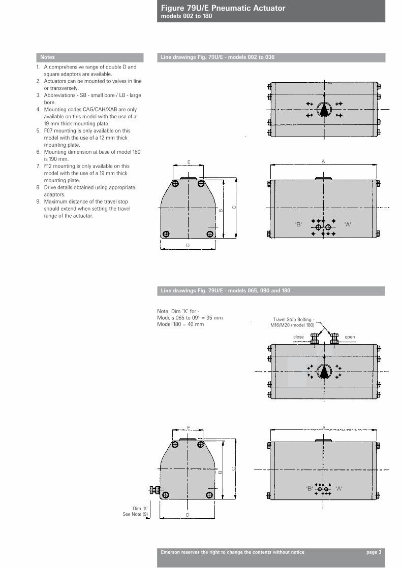
Line drawings Fig. 79U/E - models 002 to 036
Line drawings Fig. 79U/E - models 065, 090 and 180
Dim ‘X’See Note (9)
Travel Stop Bolting -M16/M20 (model 180)
close open
Note: Dim ‘X’ for -Models 065 to 091 = 35 mmModel 180 = 40 mm
Notes
1. A comprehensive range of double D and square adaptors are available.
2. Actuators can be mounted to valves in line or transversely.
3. Abbreviations - SB - small bore / LB - large bore.
4. Mounting codes CAG/CAH/XAB are only available on this model with the use of a 19 mm thick mounting plate.
5. F07 mounting is only available on this model with the use of a 12 mm thick mounting plate.
6. Mounting dimension at base of model 180 is 190 mm.
7. F12 mounting is only available on this model with the use of a 19 mm thick mounting plate.
8. Drive details obtained using appropriate adaptors.
9. Maximum distance of the travel stop should extend when setting the travel range of the actuator.
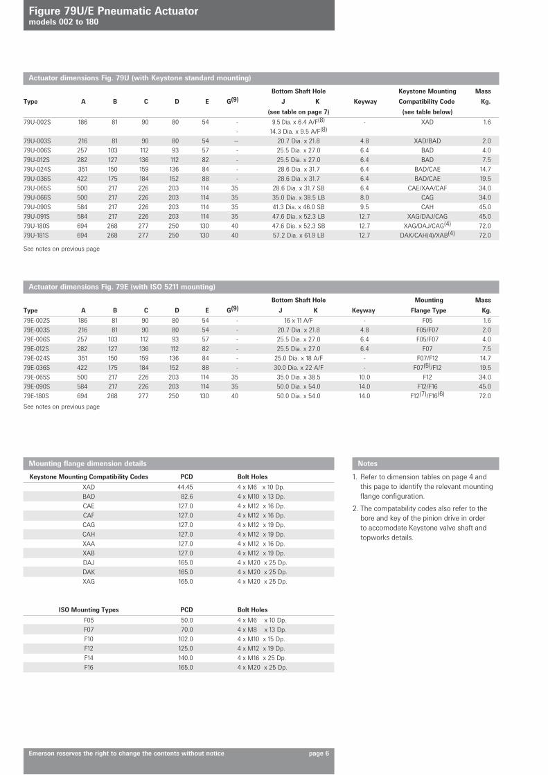
XAD 44.45 4 x M6 x 10 Dp. BAD 82.6 4 x M10 x 13 Dp. CAE 127.0 4 x M12 x 16 Dp. CAF 127.0 4 x M12 x 16 Dp. CAG 127.0 4 x M12 x 19 Dp. CAH 127.0 4 x M12 x 19 Dp. XAA 127.0 4 x M12 x 16 Dp. XAB 127.0 4 x M12 x 19 Dp. DAJ 165.0 4 x M20 x 25 Dp. DAK 165.0 4 x M20 x 25 Dp. XAG 165.0 4 x M20 x 25 Dp.
F05 50.0 4 x M6 x 10 Dp. F07 70.0 4 x M8 x 13 Dp. F10 102.0 4 x M10 x 15 Dp. F12 125.0 4 x M12 x 19 Dp. F14 140.0 4 x M16 x 25 Dp. F16 165.0 4 x M20 x 25 Dp.
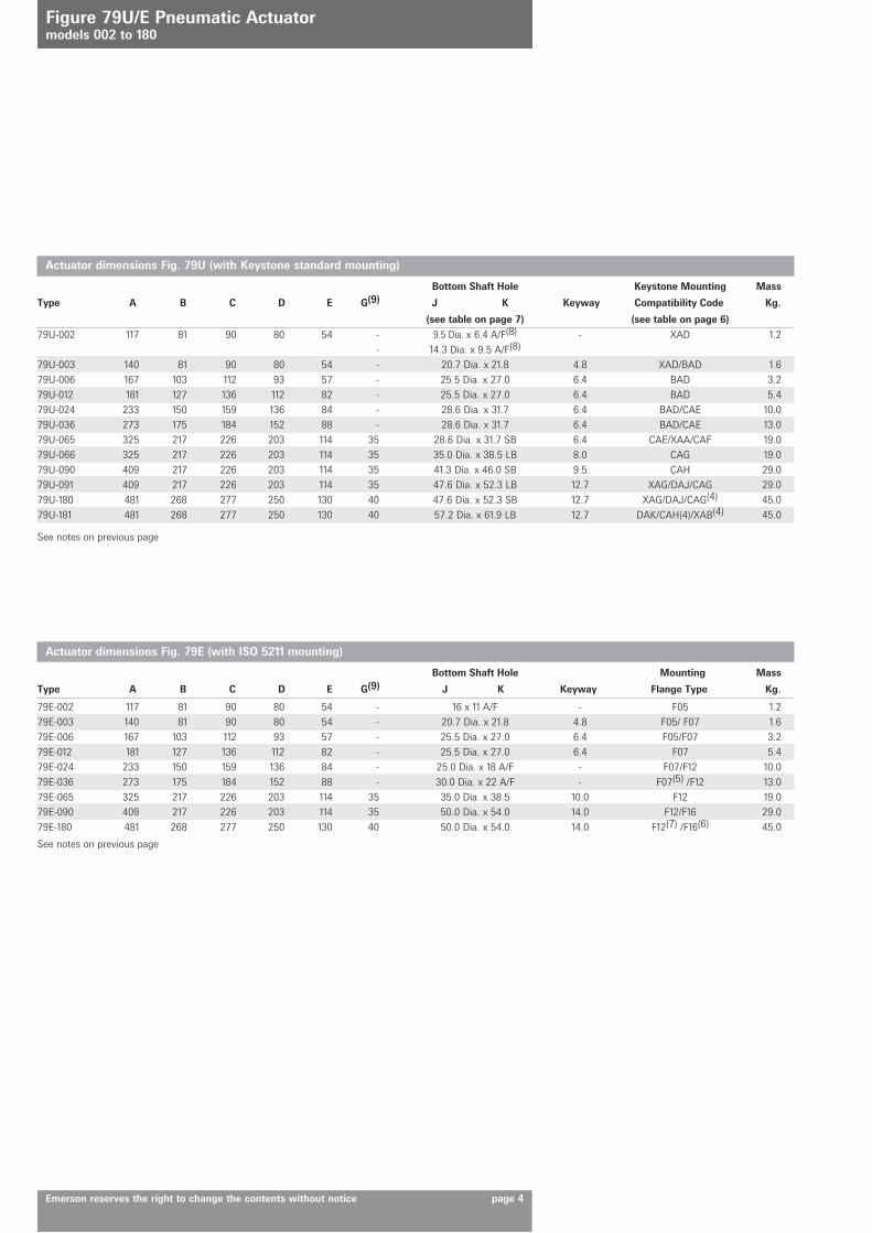
Actuator dimensions Fig. 79U (with Keystone standard mounting)
Bottom Shaft Hole Keystone Mounting Mass
Type A B C D E G(9) J K Keyway Compatibility Code Kg.
(see table on page 7) (see table below)
Actuator dimensions Fig. 79E (with ISO 5211 mounting)
Bottom Shaft Hole Mounting Mass
Type A B C D E G(9) J K Keyway Flange Type Kg.
See notes on previous page
See notes on previous page
Figure 79U/E Pneumatic Actuatormodels 002 to 180
Emerson reserves the right to change the contents without notice page 6
Notes
1. Refer to dimension tables on page 4 and this page to identify the relevant mounting flange configuration.
2. The compatability codes also refer to the bore and key of the pinion drive in order to accomodate Keystone valve shaft and topworks details.
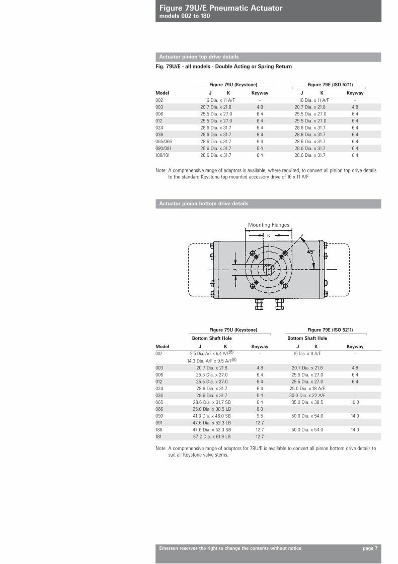
002 16 Dia. x 11 A/F - 16 Dia. x 11 A/F -003 20.7 Dia. x 21.8 4.8 20.7 Dia. x 21.8 4.8006 25.5 Dia. x 27.0 6.4 25.5 Dia. x 27.0 6.4012 25.5 Dia. x 27.0 6.4 25.5 Dia. x 27.0 6.4024 28.6 Dia. x 31.7 6.4 28.6 Dia. x 31.7 6.4036 28.6 Dia. x 31.7 6.4 28.6 Dia. x 31.7 6.4065/066 28.6 Dia. x 31.7 6.4 28.6 Dia. x 31.7 6.4090/091 28.6 Dia. x 31.7 6.4 28.6 Dia. x 31.7 6.4180/181 28.6 Dia. x 31.7 6.4 28.6 Dia. x 31.7 6.4
002 9.5 Dia. A/F x 6.4 A/F(8) - 16 Dia. x 11 A/F -
14.3 Dia. A/F x 9.5 A/F(8)
003 20.7 Dia. x 21.8 4.8 20.7 Dia. x 21.8 4.8006 25.5 Dia. x 27.0 6.4 25.5 Dia. x 27.0 6.4012 25.5 Dia. x 27.0 6.4 25.5 Dia. x 27.0 6.4024 28.6 Dia. x 31.7 6.4 25.0 Dia. x 18 A/F -036 28.6 Dia. x 31.7 6.4 30.0 Dia. x 22 A/F -065 28.6 Dia. x 31.7 SB 6.4 35.0 Dia. x 38.5 10.0066 35.0 Dia. x 38.5 LB 8.0090 41.3 Dia. x 46.0 SB 9.5 50.0 Dia. x 54.0 14.0091 47.6 Dia. x 52.3 LB 12.7180 47.6 Dia. x 52.3 SB 12.7 50.0 Dia. x 54.0 14.0181 57.2 Dia. x 61.9 LB 12.7
Figure 79U/E Pneumatic Actuatormodels 002 to 180
Emerson reserves the right to change the contents without notice page 7
Actuator pinion top drive details
Fig. 79U/E - all models - Double Acting or Spring Return
Figure 79U (Keystone) Figure 79E (ISO 5211)
Model J K Keyway J K Keyway
Figure 79U (Keystone) Figure 79E (ISO 5211)
Bottom Shaft Hole Bottom Shaft Hole
Model J K Keyway J K Keyway
Actuator pinion bottom drive details
Note: A comprehensive range of adaptors is available, where required, to convert all pinion top drive details to the standard Keystone top mounted accessory drive of 16 x 11 A/F
Note: A comprehensive range of adaptors for 79U/E is available to convert all pinion bottom drive details to suit all Keystone valve stems.
Mounting Flanges
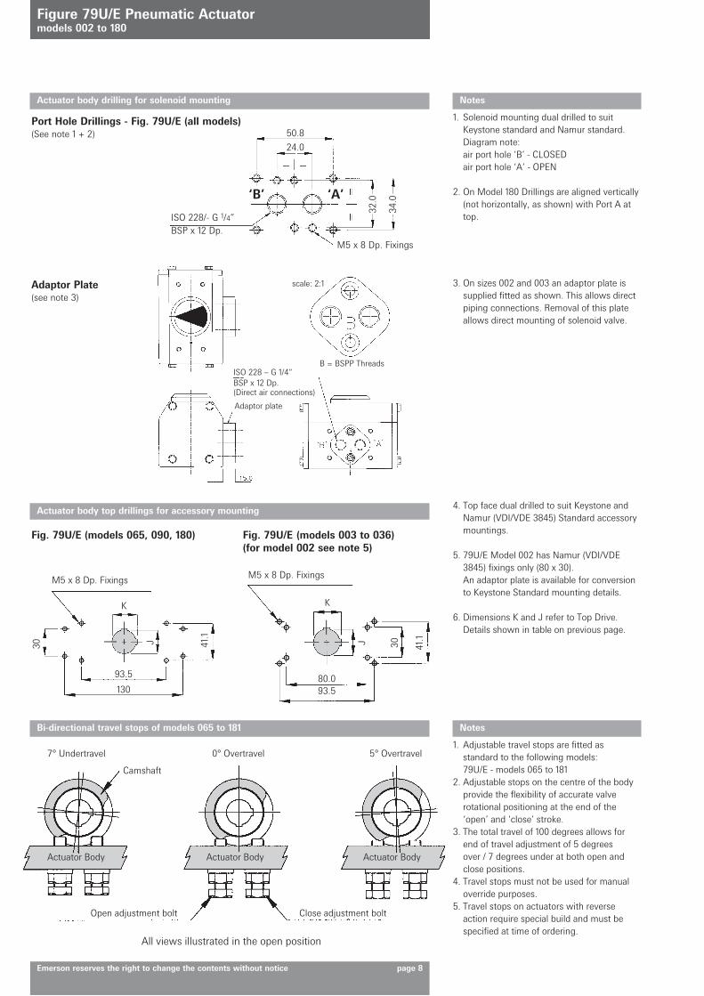
80.093.5
30 41.1
41.1
30
93.5
130
K
J
K
J
Notes
1. Solenoid mounting dual drilled to suit Keystone standard and Namur standard.
Diagram note: air port hole ‘B’ - CLOSED air port hole ‘A’ - OPEN
2. On Model 180 Drillings are aligned vertically (not horizontally, as shown) with Port A at top.
3. On sizes 002 and 003 an adaptor plate is supplied fitted as shown. This allows direct piping connections. Removal of this plate allows direct mounting of solenoid valve.
4. Top face dual drilled to suit Keystone and Namur (VDI/VDE 3845) Standard accessory mountings.
5. 79U/E Model 002 has Namur (VDI/VDE 3845) fixings only (80 x 30). An adaptor plate is available for conversion to Keystone Standard mounting details.
6. Dimensions K and J refer to Top Drive. Details shown in table on previous page.
Actuator body drilling for solenoid mounting
Actuator body top drillings for accessory mounting
Fig. 79U/E (models 003 to 036)(for model 002 see note 5)